Post Syndicated from ManojKumar MV original https://aws.amazon.com/blogs/architecture/building-cloud-native-pacs-on-aws/
Modernizing medical imaging infrastructure is a pressing challenge for multi-hospital networks. Cloud-native PACS (Picture Archiving and Communication System) on AWS can help address the challenge at scale. A hospital chain with multiple facilities generates millions of imaging studies annually: each CT produces 300 to 2,000 DICOM images, MRI generates 500 to 3,000 slices, and digital mammography produces 8 to 12 high-resolution images.
At this scale, a typical network accumulates 50 to 200 terabytes of new imaging data yearly, with retention mandated for 7 to 10 years. The traditional approach used on-premises PACS with SAN or NAS storage at each hospital independently. This worked when volumes were modest, but as chains grow through acquisition, the constraints of this siloed architecture become apparent.
In this post, we present a hybrid cloud architecture pattern for PACS on AWS. We describe the core components, explain how data flows from imaging devices to a centralized cloud archive, and outline storage tier options and capacity planning guidance. This post is for healthcare IT architects and solutions architects familiar with DICOM workflows.
Challenges that do not scale
- Storage cost explosion: Enterprise SAN/NAS requires hardware refresh every 3-5 years with annual maintenance contracts consuming 15-20% of hardware cost. Organizations must over-provision storage for projected peak capacity years in advance.
- Data silos: A patient scanned at Hospital A cannot have images viewed at Hospital B within the same chain.
- Radiologist reporting bottleneck: When a radiologist is unavailable, studies pile up with no mechanism to route to available readers at other facilities.
- Continuous archive growth: PACS/VNA storage must scale indefinitely with no capacity ceiling and no upfront provisioning of unused capacity.
How traditional PACS works today
The workflow begins when a clinician orders an imaging study. The Radiology Information System (RIS) fills the order and populates the modality worklist. The technologist selects a patient entry from the modality worklist and acquires a study. The scanner transmits DICOM objects to the PACS server through C-STORE on the hospital LAN (TCP port). A DICOM object contains image metadata and pixel data.
The PACS server ingests DICOM images and HL7 orders. It archives images on local SAN/NAS, indexes metadata, and notifies the radiologist worklist. The radiologist reviews images with patient history and creates a report. The report flows back to the EMR through HL7 messaging.
The following diagram shows the traditional on-premises PACS workflow and its limitations.
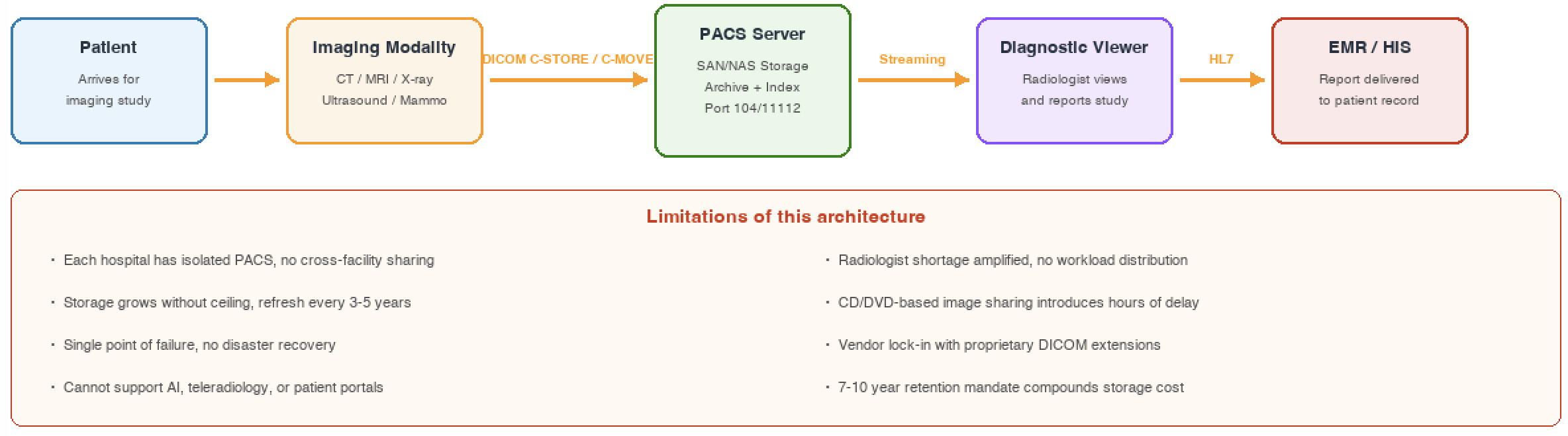
Figure 1: Traditional on-premises PACS workflow
DICOM protocol: The language of medical imaging
DICOM (Digital Imaging and Communications in Medicine) is a widely adopted standard for storing, transmitting, and viewing medical imaging files. DICOM specifies a binary file format encapsulating pixel data and metadata and defines network services including DIMSE (DICOM Message Service Element) services: C-STORE (send), C-FIND (query), C-MOVE (retrieve), and C-ECHO (verify connectivity).
DICOM DIMSE services are designed for LAN. They facilitate interoperability and image exchange on the hospital campus.
DICOMweb is a set of RESTful services that web developers use to access DICOM-enabled systems with industry-standard toolsets.
Key components of a PACS architecture
Every PACS, regardless of vendor or deployment model, consists of six core building blocks. Cloud migration does not replace these components. Instead, it re-hosts and enhances them with cloud-native capabilities. The following diagram and table describe each component and its role in architecture.
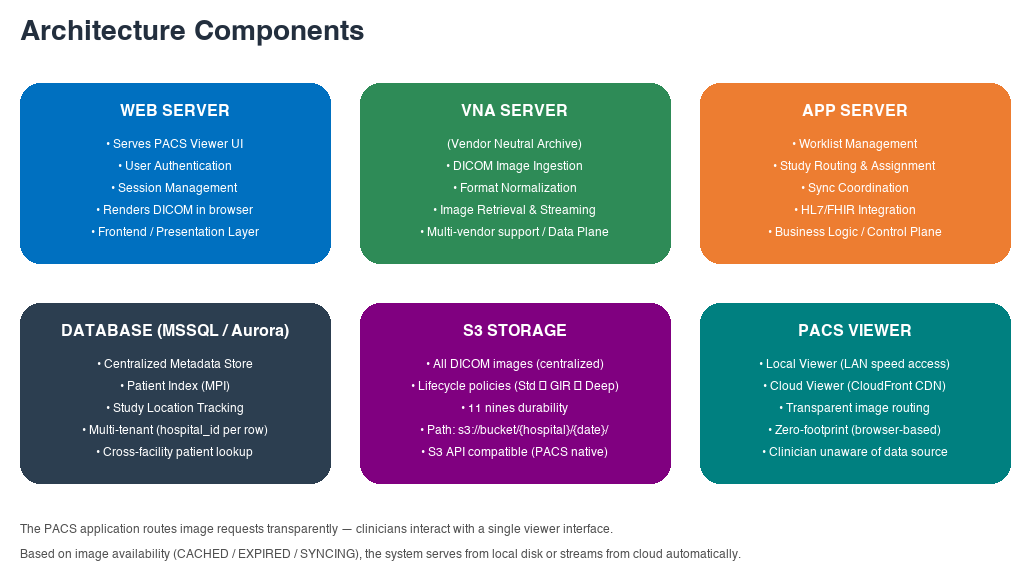
Figure 2: Six core components of a PACS architecture
Component breakdown
The following table summarizes each component, its role, and how it operates within the architecture.
| Component | Role | How it works |
| Web Server | Serves PACS viewer UI, authentication, session management | Renders DICOM in browser with windowing, leveling, and measurement tools. Zero-footprint, no client install required. |
| VNA Server | DICOM ingestion, format normalization, image streaming | Receives C-STORE from modalities on LAN. Normalizes multi-vendor encoding. Compresses and stores objects. |
| Application server | Worklist management, study routing, sync coordination | Routes studies by urgency and subspecialty. Integrates with HIS/EMR through HL7 v2 or FHIR REST APIs. |
| Database | Patient MPI, study location tracking, sync state | Stores everything except pixels: demographics, modality, storage location. Supports cross-facility patient lookup. |
| Object Storage | All DICOM images centralized, lifecycle-managed | Replaces SAN/NAS with scalable pay-per-use storage. Lifecycle policies auto-tier by age and access. |
| PACS Viewer | Local + Cloud dual viewer with transparent routing | Routes requests to local or cloud viewer based on image availability. Clinicians remain unaware of data source. |
How the components interconnect
An imaging device completes acquisition and sends DICOM objects to the VNA through C-STORE over the hospital LAN. The VNA normalizes encoding, applies compression, and writes standardized image bytes to storage.
The Application server updates the metadata database with the complete study record. It then evaluates routing rules to assign the study to the appropriate radiologist worklist based on urgency and subspecialty.
When a clinician opens a study, the PACS Viewer checks image location in the metadata database. Locally cached studies serve at LAN speed. Expired cache studies stream from the cloud viewer through a content delivery network. The clinician interacts with a single interface and remains unaware of the backend source.
Cloud-native PACS architecture on AWS
This architecture pattern applies to hospital networks that run a single PACS vendor consistently across all facilities. A common infrastructure across every site and the cloud is what allows the centralized system to discover and retrieve studies from any hospital in the network. The recommended architecture follows a hub-and-spoke model. Local PACS instances at each hospital (spokes) connect to a centralized cloud archive (hub) through AWS Direct Connect or AWS Site-to-Site VPN. This approach preserves quick image retrieval for daily clinical workflow while providing cross-facility interoperability, disaster recovery, and intelligent storage tiering.
The following diagram shows the centralized PACS architecture on AWS with hub-and-spoke connectivity.
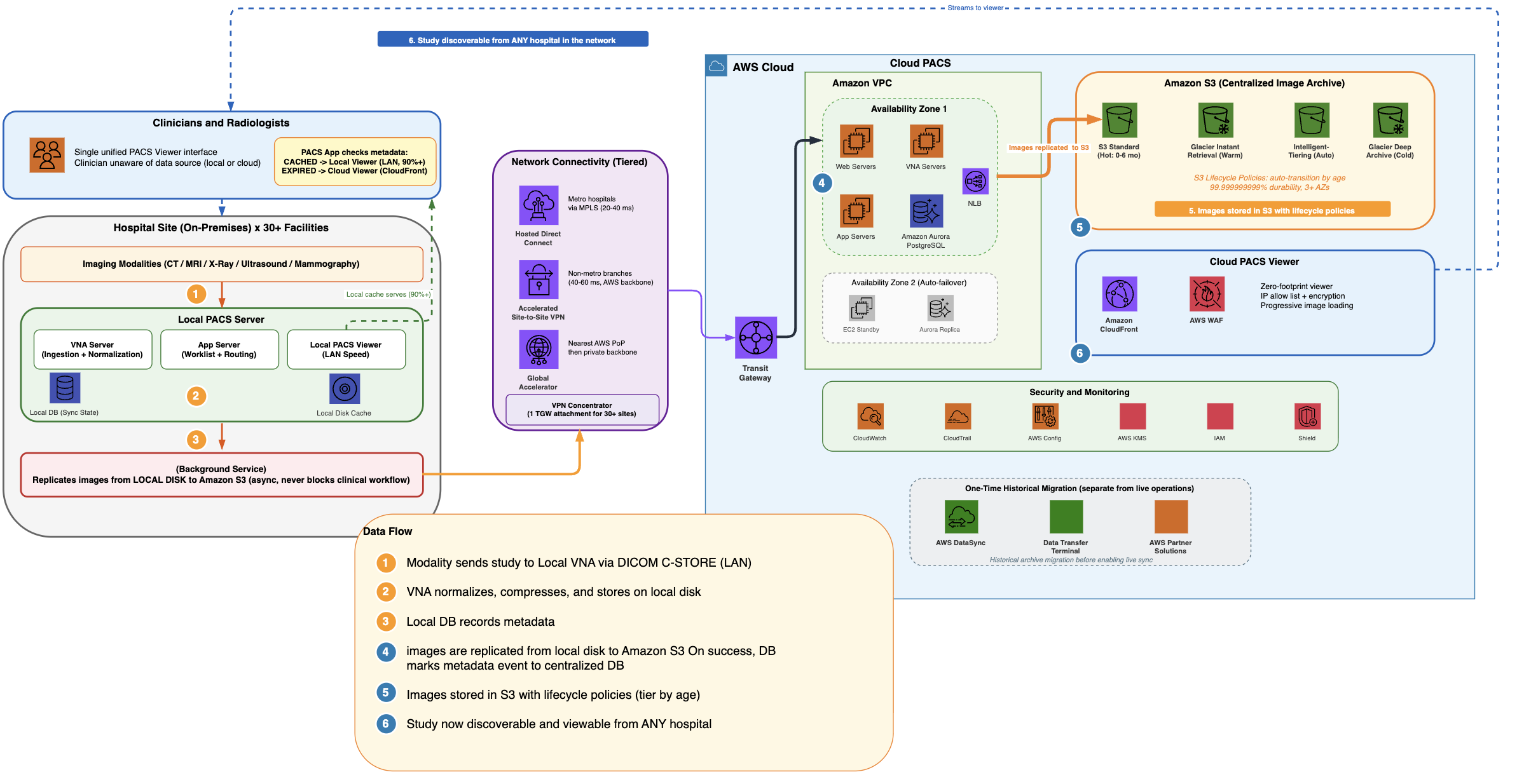
Figure 3: Centralized PACS architecture on AWS
Architecture flow
Each hospital retains a local PACS with Web Server, VNA, Application server, and local database. Imaging modalities send DICOM objects to the local VNA over the hospital LAN. Studies are immediately available for radiologist reading at LAN speed.
A single PACS vendor is deployed consistently across all hospital sites and in the cloud. Because every site and the centralized cloud archive run the same system sharing a common metadata database, the cloud-based system can discover and retrieve studies created at any facility in the network. A radiologist at one hospital can query and open a study acquired at any other hospital, giving the enterprise a unified patient imaging record.
In the background, the images generated from new studies are replicated to Amazon Simple Storage Service (Amazon S3) through Direct Connect or Site-to-Site VPN. Clinical workflow is never blocked because sync happens asynchronously.
On the cloud side, the centralized PACS runs across two Availability Zones in AWS Region. Web Servers, VNA Servers, and App Servers on Amazon Elastic Compute Cloud (Amazon EC2) sit behind Network Load Balancers with automatic failover. Amazon Aurora PostgreSQL serves as the centralized metadata store with synchronous replication.
Amazon S3 stores DICOM images with lifecycle policies that automatically tier data by access patterns. Amazon CloudFront and AWS WAF deliver the cloud PACS viewer for teleradiology access with IP allow list and encryption.
Transparent viewer experience
When a clinician requests a study, the PACS application checks the metadata database for image location. If the local system has cached the study (the majority of daily requests), it serves the images from local disk at LAN speed.
If the local cache has expired, the cloud viewer streams from Amazon S3 through Amazon CloudFront with progressive loading.
High availability and disaster recovery
The cloud deployment spans two Availability Zones with automatic failover. Amazon S3 replicates objects across multiple Availability Zones. On the local side, the cache serves recent studies if cloud connectivity drops.
If a local server fails, requests route to the cloud where all recent data is already synced. If cloud connectivity drops, the local cache continues serving recent studies without interruption. If a single AZ fails, automatic failover routes traffic to the surviving AZ within seconds.
Data protection and security controls
Medical imaging data contains sensitive patient information including patient names, dates of birth, and clinical findings in DICOM metadata. Under the AWS shared responsibility model, AWS secures the cloud infrastructure, while the customer configures services, manages access, and implements audit controls.
The architecture uses AWS services including Amazon S3 (encrypted image storage), Amazon Aurora (encrypted metadata), Amazon EC2 (encrypted compute), Direct Connect (private connectivity), Amazon CloudFront (encrypted viewer delivery), and AWS Key Management Service (AWS KMS) (key management with rotation).
The architecture includes security controls that healthcare organizations can use as part of their security programs: encryption at rest and in transit across every layer, comprehensive audit logging with AWS CloudTrail and Amazon S3 access logs, least-privilege access through IAM with role-based controls, and continuous monitoring with AWS Config.
For data residency, deploying in a regional AWS location keeps sensitive patient data within national borders. S3 bucket policies can enforce region-level restrictions for organizations with specific data sovereignty requirements.
Storage tier planning
Running PACS on AWS provides the ability to use Amazon S3 storage tiers that align cost with access patterns. Traditional on-premises SAN/NAS stores data on a single expensive tier regardless of access frequency. Amazon S3 provides intelligent lifecycle management that reduces storage costs while improving durability.
Understanding access patterns is key
Traditional on-premises storage uses a single tier for data regardless of access frequency. Amazon S3 provides multiple tiers that align cost with how often data is accessed.
Medical imaging data follows a predictable decline in access frequency: frequent in the first months (reporting, follow-ups), dropping sharply after 6 to 12 months, and rarely accessed after 2-3 years. Mapping this pattern to storage tiers is a high-impact cost optimization decision.
This predictable decline in access frequency makes PACS an ideal workload for tiered storage. The key questions to answer are: how long do radiologists typically reference prior studies? What is your average follow-up window? What percentage of archived studies are ever retrieved after 12 months? These answers drive the lifecycle policy configuration.
S3 Standard: Hot storage for active studies
Studies in their first 6 months to 1 year are actively accessed. Radiologists reference them for follow-up comparisons. Clinicians review them during patient visits. Reporting workflows are still active.
These studies sit on S3 Standard, which provides millisecond access with high throughput. This is equivalent to the performance clinicians expect from traditional local SAN, but without the upfront costs, hardware refresh cycles, or capacity planning overhead.
S3 Glacier Instant Retrieval: For warm data
S3 Glacier Instant Retrieval (GIR) provides millisecond retrieval (the same access speed as S3 Standard) at significantly lower storage cost with nominal retrieval fees. For PACS workloads, this combination of low storage cost with millisecond retrieval is particularly well suited.
When you occasionally access studies older than 6 to 12 months for comparative reads, these make ideal candidates for GIR.
This combination of instant retrieval with archive-tier pricing makes GIR well suited for medical imaging, where occasional access to historical studies is clinically important but infrequent enough to benefit from reduced storage rates.
S3 Intelligent-Tiering: When access patterns are unpredictable
For datasets with unpredictable access patterns (research hospitals, teaching institutions), S3 Intelligent-Tiering automatically moves objects between tiers based on actual usage with no retrieval fees or operational overhead.
S3 Glacier Deep Archive: Long-term retention
Studies older than 5 years that require long-term retention move to S3 Glacier Deep Archive. Retrieval takes 12 to 48 hours, acceptable for infrequent retrieval needs. Storage cost is minimal.
Why this matters for PACS
Amazon S3 replicates objects across multiple Availability Zones within a region. With Cross-Region Replication (CRR), the same archive provides built-in disaster recovery across geographically separated regions. Most modern PACS solutions support S3-compatible APIs natively, requiring no custom middleware.
Amazon S3 stores every object redundantly across multiple physically separated Availability Zones within a region. With Cross-Region Replication (CRR), organizations can maintain a full disaster recovery copy in a secondary region with no additional infrastructure to manage.
The majority of modern PACS solutions natively support writing and reading data through S3-compatible APIs. This eliminates the need for complex storage integration configurations or proprietary connectors.
Cloud-only vs. hybrid: Making the decision
The choice between a fully cloud-based PACS and a hybrid (local + cloud) deployment is not driven by imaging volume. High-volume sites operate successfully in both models. The right answer depends on two factors specific to each facility.
Cloud-only PACS is a strong fit when:
- Redundant, reliable connectivity is available. The facility’s region has well-established, high-bandwidth links to the cloud from at least two independent network carriers, ensuring no single point of failure for clinical workflows.
- The PACS vendor offers a cloud-optimized solution. The solution delivers equal or faster performance when deployed in the cloud compared to on-premises. This is achievable today: vendors running entirely on AWS have publicly demonstrated faster image retrieval than traditional on-premises deployments, even at enterprise scale.
This model eliminates local infrastructure, removes hardware refresh cycles, and centralizes operations across all sites.
Hybrid PACS (local + cloud) is a strong fit when:
- Connectivity is limited or single carrier. Regions where redundant high-bandwidth links are not yet available, or where network reliability does not meet clinical uptime requirements.
- The PACS solution performs best with local caching. Some vendor architectures are optimized for local-first access, with a site cache providing sub-second retrieval for active studies while background sync handles cloud replication asynchronously.
This model ensures uninterrupted clinical performance regardless of WAN conditions and provides a natural migration path toward cloud-only as connectivity and vendor solutions mature.
Both architectures use AWS as the durable, long-term archive. The difference is where the active working set lives day-to-day.
Conclusion
The hybrid cloud architecture described in this document is designed to help address the core on-premises PACS challenges: storage cost explosion, data silos across facilities, radiologist routing bottlenecks, and unbounded archive growth.
Next step: Conduct a device inventory and access pattern analysis to turn this conversation into a numbers-driven plan.