Tag Archives: serverless

Building a serverless AI assistant at Pelago: concept to care in two weeks

Post Syndicated from Anton Aleksandrov original https://aws.amazon.com/blogs/architecture/building-a-serverless-ai-assistant-at-pelago-concept-to-care-in-two-weeks/

Healthcare organizations face a critical scaling challenge – how to maintain deeply personalized patient interactions as member bases grow, without overwhelming care teams or compromising quality. At Pelago, a digital health company specializing in substance use disorder support, the engineering team found a way to build an AI-powered solution to address this challenge using AWS services in just two weeks.

In this post, you will learn how Pelago used AWS serverless and AI services, such as Amazon Bedrock and AWS Lambda, to build and deploy an event-driven AI assistant. The result is a service that generates contextually aware suggested considerations for the care team. This system preserves the human-in-the-loop oversight that healthcare demands while removing months of traditional development work and overhead of managing complex infrastructure.

The challenge overview

Pelago is a digital clinic for substance use treatment that provides comprehensive support including 1:1 coaching, medication management, and behavioral therapy. It serves members across the US to support recovery journeys for alcohol, tobacco, stimulants, cannabis, and opioid use disorder, and adjacent behaviors often associated with substance use. The Pelago care team coaches members through substance use recovery. A single coach may hold active conversations with dozens of members at once. Each message a coach sends needs to reflect weeks of prior context and drafting that response manually from scratch takes time the care team doesn’t always have.

When the Pelago engineering team set out to build an AI assistant for the care team, they faced a set of interconnected constraints. Behavioral health conversations build over weeks and months. Coaches need to account for that history in every reply. An AI assistant that only understands the most recent messages isn’t useful here – it must grasp the full long-term conversation history. That depth of context is also why human oversight is non-negotiable. The system had to generate suggestions for Pelago’s care team, not automated responses. Every piece of feedback must be read, evaluated, and adapted by a human coach before it reaches a member.
Protected Health Information (PHI) requirements added another layer of complexity – data could not leave Pelago’s AWS environment. All AI integrations must operate entirely within existing Amazon Virtual Private Cloud (VPC) infrastructure with no exposure to the public internet.

Beyond compliance and clinical safety, there were also practical constraints. Care team members need information the moment they open a conversation but generating relevant content processing dozens, sometimes hundreds, of prior messages through a large language model. A long wait was not acceptable when coaches open dozens of conversations per shift.

The engineering team needed to deliver all this quickly with full audit trails and security controls in a highly regulated environment. They had to solve the problem of pre-generating contextual suggestions without blocking the user experience while maintaining the compliance posture.

Solution design: Event-driven serverless architecture

The Pelago team separated concerns using event-driven architecture. The care team needed suggested responses instantly when accessing the system but generating them synchronously in real-time blocked the user experience for tens of seconds because of LLM processing time. By treating each incoming member message as an asynchronous event, the system can fan out processing to independent consumers without coupling them to the message delivery path. A new consumer, such as the AI assistant, can be added without affecting existing components or code. And because each processing step runs in its own Lambda function, a spike in inference requests doesn’t affect message delivery or processing.

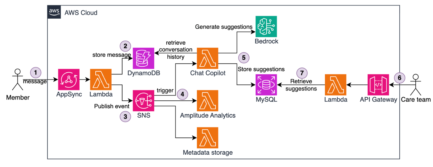
End-to-end solution architecture showing the event-driven flow from member messages through SNS fanout to AI suggestion generation and retrieval

Figure 1 — The full end-to-end solution architecture

The architecture uses Amazon Simple Notification Service (Amazon SNS) for message fanout and Lambda functions for processing. Here’s how it works:

  1. Members send messages through AWS AppSync, forwarded to a Lambda function.
  2. The Lambda function stores messages in an Amazon DynamoDB table.
  3. The Lambda function publishes messages to an SNS topic.
  4. SNS fans out messages to multiple Lambda subscriber functions, such as Metadata storage, Amplitude analytics, and Chat assistant responsible for AI-based suggested message generation.
  5. The Chat Assistant Lambda runs asynchronously. It retrieves the full conversation history from DynamoDB, invokes Amazon Bedrock to generate contextual suggestions, and stores the result in MySQL hosted on Amazon Relational Database Service (Amazon RDS). This flow happens in the background without blocking user experience and typically completing in under 10 seconds.
  6. When a care team member opens a conversation (often minutes or hours later), the request flows through Amazon API Gateway.
  7. A Lambda function retrieves pre-generated suggestions from MySQL.
  8. The front end displays the suggestion in under 100 milliseconds.

This pattern keeps message delivery, analytics, and AI generation decoupled. Each member’s PHI is processed separately and stays fully within the Pelago AWS boundary. A failure or spike in feedback generation for one member does not disrupt or impact processing for other members.

Because inference happens asynchronously in the background, the care team does not wait for LLM processing. Suggested messages are pre-generated, stored, and ready to use when a coach opens a conversation. This keeps retrieval times under 100 milliseconds regardless of how long the AI generation took.

This serverless architecture also provides organic scaling. Each Lambda function automatically scales horizontally based on current traffic – scaling up during spikes and back down when demand drops, with no pre-provisioning or scaling configuration required. Adding a new event-driven downstream capability, like the AI assistant itself, requires only a new SNS subscription with no changes to existing message-publishing or handling code.

Event-driven fanout with Amazon SNS

The foundation of the Pelago chat architecture is an SNS topic that acts as a message bus for conversation events. SNS is a fully managed pub/sub messaging service. When a message is published to a topic, SNS automatically delivers it to subscribed consumers in parallel. This means a single incoming message can trigger multiple independent processing steps simultaneously.

When a user or coach sends a message, the system publishes a standardized payload to the SNS topic, for example:

{
    "identityId": "085cdc3c-f223-419a-9c80-5535c9983549",
    "messageId": "7a4d2b8e-1c9f-4e3a-b5d6-8f2e1a3c4b5d",
    "sender": "user",
    "timestamp": "2025-07-15T14:32:18Z",
    "conversationId": "conv-abc123"
}

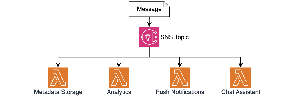
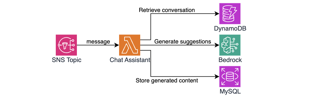
SNS delivers this event to four Lambda function subscribers. The Metadata Storage Lambda writes message metadata to MySQL for reporting. The Analytics Lambda sends events to Amplitude for product analytics. The Push Notification Lambda triggers mobile notifications for coaches. The Chat Assistant Lambda generates Assistant-based suggestions using Amazon Bedrock.

SNS topic delivering events to four Lambda subscriber functions for metadata storage, analytics, push notifications, and AI suggestion generation

Figure 2 — Using SNS for message fan-out and decoupled processing

This fanout pattern allowed the Pelago team to add the AI Chat Assistant feature with zero changes to existing message-handling code. The team simply created a new Lambda function and added it as an SNS subscription. The publisher doesn’t need to know how many consumers exist or what they do, so new capabilities can be built and deployed independently without risking regressions in the message processing path.

Async AI generation with Amazon Bedrock

The Chat Assistant Lambda handles computationally expensive AI generation. The function implements a multi-step workflow:

Chat Assistant Lambda workflow showing conversation history retrieval from DynamoDB, context formatting, Bedrock inference, and suggestion storage

Figure 3 — The chat assistant architecture and workflow

The first step is to retrieve conversation history. Behavioral health conversations can span dozens or even hundreds of messages over weeks, and the AI assistant needs all that context to generate a useful suggestion to Pelago’s care team. The function queries DynamoDB for previous messages in the conversation. The DynamoDB single-digit millisecond read performance means even lengthy conversations (50+ messages) are typically retrieved in under 20ms.
# Simplified pseudocode
conversation_messages = dynamodb.query(
    TableName='conversations-messages',
    IndexName='identityId-index',
    KeyConditionExpression='identityId = :id',
    ExpressionAttributeValues={':id': identity_id}
)

The next step is to prepare and format context for inference. The function transforms the retrieved messages structure into a conversation history format that provides Amazon Bedrock with full context, for example:

[User]: Hi, I'm struggling with cravings today

[Coach]: I hear you. Cravings can be really tough. What's happening right now that's making this moment difficult?

[User]: I'm at a party and everyone is drinking. I feel left out.

[Coach]: That's a really challenging situation, and it's completely understandable to feel that way...

[User]: I ended up leaving early. Feeling proud but also kind of sad.

After formatting the conversation, the Lambda function uses the Amazon Bedrock Runtime API to invoke Claude models. The prompt engineering focuses on empathy and validation – it helps the model acknowledge what the member is feeling rather than jumping to advice. It is tuned to maintain contextual continuity – picking up things the member mentioned in earlier messages instead of treating each exchange without prior context. It also steers the model away from false optimism or dismissive language and keeps suggestions short, more like a text message than an email. This matches how coaching conversations flow on the application.

response = bedrock_runtime.invoke_model(
    body=json.dumps({
        "anthropic_version": "bedrock-2023-05-31",
        "max_tokens": 4096,
        "temperature": 0.7,
        "system": "You are a supportive coach...",
        "messages": [{
            "role": "user",
            "content": f"""
Here is the conversation history:

<chatHistory>
{chat_history_string}
</chatHistory>

Provide the next coach message suggestion as plain text.
"""
        }]
    })
)

Measuring system performance and business impact

This entire flow, from SNS trigger to a suggestion stored in MySQL, typically completes in less than 4 seconds, well within acceptable processing time. When a care team member opens a conversation on the dashboard, the front end instantly retrieves pre-generated suggested messages. Total response time perceived by the care team is under 100 milliseconds.

The Pelago team went from technical designs to first production deployment in 2 weeks. Two days on architecture and model selection with the clinical team, three days building the core Lambdas, three days on integration testing and prompt refinement, and two final days on deployment and monitoring.

The system delivered strong early results. From the business perspective, response preparation times dropped 40% on average, and the care team rated 79.6% of AI suggestions as helpful, based on internal Pelago measurements. Operationally, using serverless services introduced no new overhead. There was no new infrastructure to manage, servers to patch, or scaling configurations to maintain. The architecture successfully handled an 8x message volume spike during a seasonal campaign without configuration changes.

Implementation details and key decisions

With the core event-driven architecture in place, the Pelago team made several implementation choices to satisfy healthcare industry requirements, handle traffic patterns unique to the application, and maintain reliability across the system.

PHI must stay secured

Pelago uses multiple AWS security features to maintain HIPAA eligibility while using AI models. One requirement is for PHI to never traverse the public internet. To address this, the Pelago team uses VPC endpoints for Amazon Bedrock, so model invocations stay within the private network. The Boto3 client in the Python Lambda automatically routes traffic through the private endpoint. Data is encrypted at rest on DynamoDB and RDS, service communications use TLS 1.2+, and IAM policies are scoped with least-privilege permissions to specific resource actions and ARNs. Audit logs of model invocations are emitted to Amazon CloudWatch and capture message IDs only, not content.

Polyglot cross-runtime implementation

The team used Python for Lambda functions that invoke Amazon Bedrock models. Boto3 native Amazon Bedrock support and simpler string manipulation made Python the right choice for building and iterating on prompts. The retrieval function is written in TypeScript to stay consistent with most of the Pelago backend code and to reuse shared libraries and Zod schemas for type-safe API contracts. This split let the team use the best language for each job without forcing a single runtime across the entire system.

Spiky traffic and pay-per-invocation compute

The Pelago application serves heavily US-based traffic. Message volume concentrates during weekday working hours, with peak hours seeing 10x or more the volume of quiet periods. The pay-per-invocation model of Lambda fits this well. During a Monday morning surge, Lambda scales out automatically with no pre-provisioning required. During off-peak hours, Lambda functions automatically scale down, so Pelago avoids idle compute costs. Using alternative long-lived compute would mean either over-provisioning for peak load or maintaining auto scaling policies that can lag during sudden spikes. With Lambda, the solution costs are directly proportional to member engagement with no idle cost.

Picking the right storage and handling idempotency

The team chose to use DynamoDB for conversation messages and MySQL for assistant suggestions based on different access patterns of each scenario. Conversation messages require high write throughput (100+ writes/sec at peak), single-digit millisecond reads, and automatic scaling. These requirements made DynamoDB a good fit. Assistant suggestions have a lighter write load (10-20 writes/sec) but need structured queries, foreign key relationships, and nested analytics joins that a relational database supports naturally.

Because SNS can deliver messages more than once, the Chat Assistant Lambda checks MySQL for an existing message before generating a new one. This idempotency check helps prevent duplicate Amazon Bedrock invocations, which would waste compute and could surface conflicting suggestions to coaches. If an Amazon Bedrock invocation fails because of throttling or model unavailability, the function logs the error without blocking message flow. A built-in retry mechanism handles transient failures, so suggestions are eventually generated even when Amazon Bedrock experiences momentary capacity constraints.

Monitoring and observability

The team tracks multiple business and operational metrics. CloudWatch metrics capture suggestion generation latency, which helps the team identify when model response times exceed acceptable thresholds. Retrieval rate measures what percentage of generated message suggestions are used by coaches. This gives insights into how well the async timing aligns with real usage patterns. The system also allows coaches to rate each suggestion with thumbs up or down. These ratings are stored in MySQL for future prompt tuning and model evaluation. CloudWatch alarms monitor error rates for Amazon Bedrock throttling and database connection failures. These alarms alert the engineering team before operational issues impact the care team experience.

Conclusion

Managed AI services like Amazon Bedrock and serverless architectures let healthcare organizations move quickly while maintaining compliance controls. The Pelago chat assistant shows what’s possible when you combine serverless event-driven processing with async AI generation and fast synchronous retrieval. The key patterns that made this work are SNS fanout to decouple processing and make new features straightforward to add, pre-generating message suggestions asynchronously so the care team does not wait, VPC endpoints to keep PHI off the public internet, and starting with foundation models and prompt engineering instead of spending months on custom model training.

The Pelago journey from concept to production deployment shows how small engineering teams in regulated industries can balance moving fast and maintaining their compliance posture.


About the authors

Serverless ICYMI Q2 2026

Post Syndicated from Julian Wood original https://aws.amazon.com/blogs/compute/serverless-icymi-q2-2026/

In this 33rd quarterly recap post, discover the most impactful AWS serverless launches, features, and resources from Q2 2026 that you might have missed. Stay current with the latest serverless innovations that can improve your applications.

In case you missed our last ICYMI, read about what happened in Q1 2026.

Serverless ICYMI Q2 2026 banner

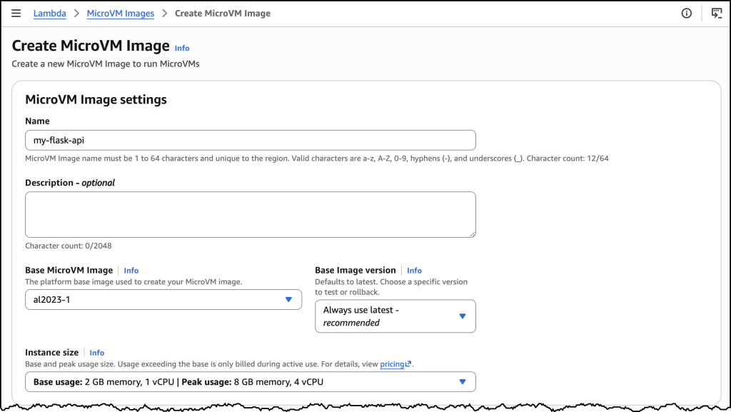
AWS Lambda MicroVMs

AWS Lambda MicroVMs is a new serverless compute primitive for running user or AI-generated code in isolated, stateful execution environments. Built on the same Firecracker virtualization that powers over 15 trillion monthly Lambda invocations, MicroVMs give you VM-level isolation with near-instant launch and resume. Each MicroVM runs in its own Linux environment with no shared kernel or resources between sessions. This isolation makes it a useful solution for AI coding assistant sandboxes, interactive code or multi-tenant development environments, CI/CD build environments, data analytics platforms, vulnerability scanners, and game servers that run user-supplied scripts.

Standard Lambda functions are best for event-driven, request-response workloads which have a 15-minute timeout. MicroVMs are purpose-built for single end user or session workloads and can preserve state for up to 8 hours. You get full lifecycle controls including launch, suspend, resume, and terminate. You can suspend them during the 8 hours if you don’t need them active. MicroVMs retain memory and disk state for the length of the session, even while suspended. They can auto resume when you need to use them again.

Serverless Land contains example applications and a resources page with more details. The Serverless Office Hours live stream has more explanations and live demos.

Amazon S3 Files and Lambda integration

Amazon S3 Files makes your S3 buckets accessible as high-performance file systems. S3 files is a fully featured, POSIX-compatible file system to access to your data with approximately 1ms latency.

For serverless workloads, the Lambda integration with S3 Files lets your functions mount an S3 bucket as a local file system. Your function reads and writes files at a local mount path like /mnt/data, and the file system handles synchronization with S3 automatically. You can avoid downloading objects to /tmp from S3 within your function and work directly with files. Applications that assume a file system can now run on Lambda without rewriting their I/O layer. Use cases include sharing data between functions, ML model loading, document processing, media transcoding, or any pipeline that treats data as files rather than objects.

AWS Lambda durable functions

The Lambda durable functions SDK for Java is now generally available, joining Python and TypeScript. This allows Java developers to build multi-step workflows with automatic checkpointing and recovery without adding external orchestration. Durable functions is also now available in 16 additional AWS Regions. Learn how to build fault-tolerant multi-agent AI workflows to coordinate multiple AI agents that call tools, make decisions, and hand off work. There is automatic recovery if any agent fails mid-task. Voice analytics with Amazon Bedrock shows building a pipeline that processes call recordings through transcription, sentiment analysis, and summarization with durable checkpoints between each stage. For best practices, AI patterns, and futures, view the live stream.

AWS Lambda Managed Instances

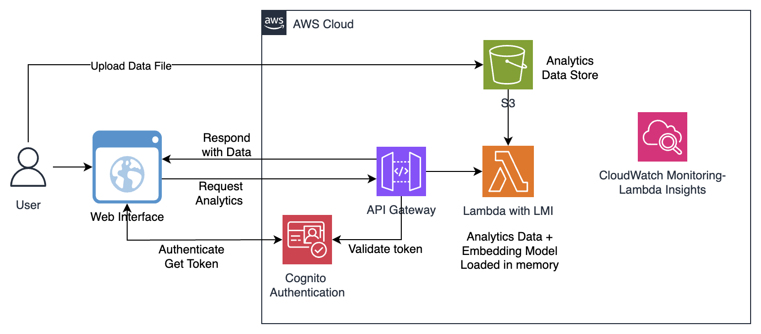
Lambda Managed Instances now allows you to build memory-intensive apps with up to 32 GB (3x more than standard Lambda). This allows use cases like in-memory caching, large dataset analytics, and ML inference that previously required considering other services.

Architecture diagram for AWS Lambda Managed Instances memory-intensive apps

Figure 1 — AWS Lambda Managed Instances for memory-intensive apps architecture

Scheduled scaling lets you pre-warm capacity for predictable traffic patterns with Amazon EventBridge Scheduler. This helps reduce cold start latency during known demand spikes. Tag propagation automatically applies your function tags to the underlying Amazon EC2 instances, Amazon Elastic Block Store volumes, and network interfaces. This helps finance teams with cost allocation visibility without manual tag management.

Other Lambda updates

Response streaming is now available in all commercial AWS Regions, bringing full regional parity for progressively streaming data back to clients. This is useful for LLM-powered applications where users expect to see tokens as they generate rather than waiting for a complete response.

The tenant isolation mode now integrates with Event Source Mappings from Amazon SQS, Amazon Kinesis, and Amazon EventBridge. Multi-tenant SaaS applications can process messages in isolated execution environments without building custom routing logic.

If you have a fleet of functions on older runtimes, you can now upgrade runtimes at scale using AWS Transform custom. This uses AI to analyze your function code, identify breaking changes for the target runtime version, and generate the code modifications needed. This can help teams save manual migration effort across many functions. The Serverless Office Hours live stream has more information.

Lambda added the Ruby 4.0 runtime. In addition to providing access to the latest Ruby language features, Lambda adds support for Lambda advanced logging controls.

AWS Serverless Application Model (AWS SAM) CLI now supports BuildKit for building container images from Dockerfiles. This allows faster multi-stage builds with better caching, cross-architecture image builds, and Docker secrets to keep credentials out of final image layers.

Containers with Mama J


Serverless with Mama J

Mama J is back in the second video of a series where Eric Johnson explains what he does all day at work to his mother. Previously, they talked serverless and Lambda. This time it’s containers, what they are, why they exist, and how AWS manages them at scale. Eric goes through the “it works on my machine” problem, how Docker builds images, container orchestration and how containers differ from Lambda.

View the video on the AWS Developers YouTube channel.

AWS Step Functions

AWS Step Functions has an Amazon Bedrock AgentCore-powered agentic reasoning step. You can embed AI agent reasoning directly inside a workflow as a native step type. This bridges structured orchestration with autonomous agent behavior. Your workflow handles the deterministic parts such as branching, retries, timeouts, parallel execution, while the agentic step handles the parts that require flexible reasoning.

Amazon EventBridge

Amazon EventBridge Scheduler added 619 new SDK API actions as targets, including Lambda Managed Instances operations. This means you can schedule calls to a much broader set of AWS APIs without writing a Lambda function.

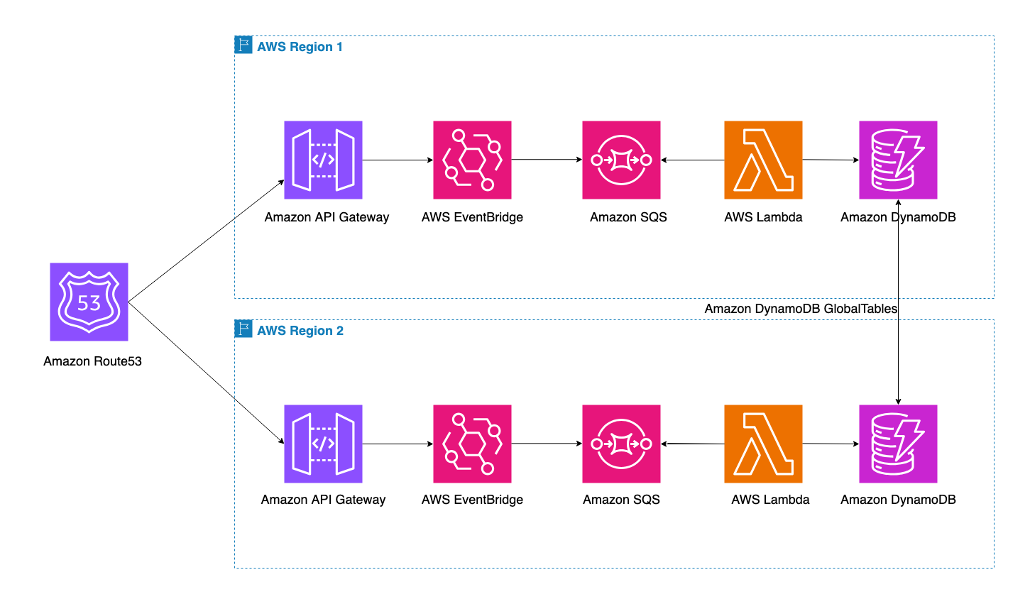
A new post walks through building a multi-Region event-driven failover architecture with Amazon EventBridge and Amazon Route 53. The pattern uses Amazon EventBridge global endpoints with Route 53 health checks to automatically route events to a healthy Region during failures. This provides active-active or active-passive resilience for event-driven workloads.

Amazon Bedrock AgentCore

The Amazon Bedrock AgentCore harness reached general availability. Two API calls give you a running agent in seconds which runs in its own isolated environment with a filesystem and shell. It can read files, run commands, and write code safely.

AgentCore Payments (preview) allows agents to autonomously access and pay for APIs and MCP servers, opening up agent-to-agent commerce. AgentCore Memory has metadata for long-term memory so agents retain and recall context across sessions. Web Search on AgentCore grounds agents in current, cited web knowledge. The Runtime now supports bring-your-own file systems from S3 Files and Amazon Elastic File System, and Node.js for direct code deployment.

Strands Agents SDK

The open source Strands Agents SDK shipped three capabilities. Context management that cuts token costs in half by intelligently pruning what goes into the model context window, Strands Shell for sandboxed agent code execution, and Strands Evals 1.0 with chaos testing and adversarial red teaming. This can reduce costs to help make production agent workloads cheaper without sacrificing quality. A Serverless Office Hours live stream covered the new features in depth.

The TypeScript SDK reached general availability, giving JavaScript and TypeScript developers the same model-driven agent framework. Erik Hanchett ran this live stream with more details. A new blog post on building research assistants with Strands walks through the full app from prototype to working application in about 200 lines of Python.

Agent Toolkit for AWS and AI coding

The Agent Toolkit for AWS became generally available with three plugins (aws-core, aws-agents, aws-data-analytics), over 30 curated skills, and the AWS MCP Server. View this video for an introduction. This gives AI coding agents such as Kiro, Claude Code, and Cursor expert AWS knowledge which helps to reduce errors and lower token costs. For more information on the serverless tools available when using AI, see this Serverless Land resources page.

Serverless Office Hours ran a live stream series finding out how experts use AI to build serverless applications. Hear from:

Kiro launched Kiro Pro Max and an iOS mobile app for approving and monitoring agentic coding sessions from your phone. Amazon Q Developer IDE plugins are transitioning to Kiro. The Kiro power for AWS DevOps Agent connects your IDE directly to production intelligence. You can investigate incidents and generate fixes without context switching.

Serverless blog posts

April

June

Serverless Office Hours

Join our live stream every Tuesday at 11 AM PT for live discussions, Q&A sessions, and deep dives into serverless technologies. View episodes on-demand at serverlessland.com/office-hours.

April

May

June

Still looking for more?

The Serverless landing page has overall information about building serverless applications. The Lambda resources page contains case studies, webinars, whitepapers, customer stories, reference architectures, and even more Getting Started tutorials.

You can also follow the Developer Advocacy team to get the latest news, follow conversations, and interact with the team.

And finally, visit Serverless Land for your serverless needs.

Your Worker can now have its own cache in front of it

Post Syndicated from Dan Lapid original https://blog.cloudflare.com/workers-cache/

Today we are launching Workers Cache: a tiered cache that sits in front of your Worker, configured by a single line of Wrangler config and the same Cache-Control headers you already know.

When Workers Cache is enabled, every cacheable request to your Worker hits Cloudflare’s cache first. If there’s a fresh cached response, Cloudflare returns it directly — your Worker doesn’t run, and you don’t pay CPU time for it. On a miss, your Worker runs, and if your response is cacheable, Cloudflare stores it for the next request. The next request from anywhere on Earth can be served straight from cache.


The whole thing is one config block:

{
  "name": "my-worker",
  "main": "src/index.ts",
  "compatibility_date": "2026-05-01",
  "cache": {
    "enabled": true
  }
}

After that, you control caching the way HTTP has always wanted you to — by setting headers on your responses:

return new Response(body, {
  headers: {
    "Cache-Control": "public, max-age=300, stale-while-revalidate=3600",
    "Cache-Tag": "products,product:123",
  },
});

And when content changes, your Worker purges its own cache:

await ctx.cache.purge({ tags: ["product:123"] });

That’s the whole API. There is no zone to configure, no rules engine to set up, no separate cache to provision, and no second product to log into. The Worker’s code is the configuration surface, and the cache follows the Worker wherever it runs — on a custom domain, on workers.dev, behind a service binding, in a preview, in a Workers for Platforms tenant. One Worker, one cache, configured once.

That’s the surface area. There’s a lot underneath: tiered caching across our entire network, full support for stale-while-revalidate so stale responses never block a user, content negotiation via Vary, multi-tenant-safe cache keys via ctx.props, programmatic purges by tag or path prefix, and — the part we think is the biggest unlock — a cache that sits in front of every Worker entrypoint, not just the public one, with per-entrypoint control over which ones cache and which don’t. That last piece means you can compose caching directly into the structure of your app: a chain of entrypoints with cache stages slotted in wherever you want them, configured by the code on either side. We’ll walk through all of it below.

Workers Cache is available today to every Worker on any plan, enabled in Wrangler.

This is the caching API we’ve always wanted Workers to have. Here’s why it took us this long, what becomes possible because of it, and what’s coming next.

Why server-rendered apps need a cache in front

When we introduced Workers in 2017, the pitch was that you could run code on Cloudflare’s network to transform requests on their way to your origin. The Worker sat in front of the cache and the origin:


This was the right model for the use cases we were targeting. If you wanted to add a header to every request, rewrite a URL, do an A/B split, or filter traffic before it reached your origin, putting the Worker in front of the cache and the origin gave you full control over what got cached and what didn’t. Customers built incredible things with it.

But the world changed. Workers stopped being a thing you bolted onto an origin and started being the origin. Frameworks like Astro, TanStack Start, Next.js, Remix, and SvelteKit all ship a Cloudflare adapter that builds your app as a Worker. There’s no origin behind them. The Worker is the server.

When the Worker is the origin, the original architecture has nothing to cache. Every request runs your code, even when the response would be byte-for-byte identical to the one you returned a second ago. The Workers runtime is fast enough that this works — it routinely handles tens of millions of requests per second without breaking a sweat — but “fast enough to render every request” still costs you latency on every page load and CPU time on every invocation. And on a server-rendered app, every page load is, by definition, a render.

Workers Cache flips the architecture. Cloudflare’s cache now sits in front of the Worker:


On a cache hit, your Worker doesn’t run at all. Cloudflare returns the cached response and your CPU billing stays at zero. On a miss, your Worker runs once, populates the cache, and the next request — from anywhere — gets served from cache without invoking your code.

This is what was missing for server-side rendering on Workers. You used to have to choose between two unsatisfying options:

  • Prerender everything at build time (“static site generation”). Fast page loads, but every change requires a full rebuild and redeploy. For a docs site with a few thousand pages, that’s 5–10 minutes. For a large e-commerce site, it’s worse — and the build runs every single time you touch anything.

  • Render every page on every request. Up-to-date content, but every page load pays the rendering cost and every visitor pays the latency.

Workers Cache gives you a third option: server-render on demand, cache the rendered response, refresh it on a time-to-live (TTL) you choose. The first request to a new page still renders. Every subsequent request, until the cache expires, is served as if the page were static. When the cache expires, the next request triggers a re-render — and with stale-while-revalidate, even that one doesn’t wait.

You get the speed of a static site without the build time, and the freshness of server rendering without the cost. No framework-specific machinery like Incremental Static Regeneration. Just HTTP caching, working the way it was designed to work, in front of code that was designed to be the origin.

stale-while-revalidate is the part that makes it feel instant

The stale-while-revalidate directive tells Cloudflare that when a cached response expires, it’s allowed to serve the stale copy immediately while it refreshes the response in the background. Cloudflare shipped full support for stale-while-revalidate earlier this year, and it’s the directive that turns “we cache your Worker” into “your Worker’s site feels static.”

Without it, the first request after a cache entry expires has to wait for the Worker to render the page from scratch. The user sees that latency. With it, the first request after expiration gets the stale page immediately (with a Cf-Cache-Status: UPDATING header), and the Worker runs in the background to refill the cache. Every user, including the one who triggered the refresh, gets a cache-speed response.


In practice, this looks like:

 export default {
  async fetch(request) {
    const html = await renderPage(request);
    return new Response(html, {
      headers: {
        "Content-Type": "text/html; charset=utf-8",
        // Treat as fresh for 5 minutes; serve stale for up to an hour
        // while a background refresh runs.
        "Cache-Control": "public, max-age=300, stale-while-revalidate=3600",
      },
    });
  },
};

The mental model that makes this click:

  • Fresh window (max-age): Cloudflare serves the cached response. Your Worker doesn’t run.

  • Stale window (stale-while-revalidate): Cloudflare serves the cached response. Your Worker runs in the background to refresh it. No user waits.

  • Outside both windows: Cloudflare runs your Worker to generate a fresh response, and the user waits for that one render.

You pick the windows. For a product catalog that updates every few minutes, max-age=300, stale-while-revalidate=3600 means visitors basically never wait, and your Worker still runs often enough to keep content fresh. For a blog archive that almost never changes, max-age=86400, stale-while-revalidate=2592000 means your Worker runs once a day per page.

The first request to a brand-new page is the only one that pays the full render cost. After that, the page behaves like static output for visitors, while your Worker still owns how the page gets generated.

One URL, many representations: Vary works

Real apps rarely return the same bytes to every client. The same product page might be HTML for a browser and JSON for an API client. The same image might be WebP for clients that support it and JPEG for the ones that don’t. The same homepage might come back in English, French, or Japanese depending on the user.

Doing this without a cache is easy — your Worker just reads the request header and returns the right thing. Doing it with a cache is where it usually gets ugly. Most caches give you two bad options: cache nothing on URLs that have multiple representations, or cache one representation and serve it to everyone.

Workers Cache supports the standard HTTP Vary header, which is the right way to solve this. When your Worker returns a response with Vary: Accept-Encoding (or Accept, or Accept-Language, or any other request header), Cloudflare stores a separate cached variant per distinct combination of those headers — and only returns a variant whose stored values match the incoming request.

export default {
  async fetch(request) {
    const accept = request.headers.get("Accept") ?? "";
    const wantsWebp = accept.includes("image/webp");

    const body = wantsWebp ? await fetchWebpImage() : await fetchJpegImage();

    return new Response(body, {
      headers: {
        "Content-Type": wantsWebp ? "image/webp" : "image/jpeg",
        "Cache-Control": "public, max-age=3600",
        // Cache a separate variant per distinct Accept header value.
        Vary: "Accept",
      },
    });
  },
};

One URL, two cached variants. A browser that sends Accept: image/webp,*/* gets the WebP. A browser that sends Accept: image/jpeg gets the JPEG. Both come from cache. Your Worker writes both variants on the first request to each, and then runs zero times for either after that.

This is the well-trodden HTTP standard for content negotiation, and Workers Cache implements it the way RFC 9110 and RFC 9111 describe. There’s no allowlist of what headers you can Vary on. You list whatever you need, and Cloudflare keys variants on the verbatim values. The docs go through the edge cases — how to keep variant fan-out under control by normalizing headers in a gateway Worker, why purges invalidate all variants of a URL together, and the one case (Vary: *) that disables caching entirely.

This is your Worker’s cache, not your zone’s

Before we get to what becomes possible with all this, there’s a conceptual shift worth naming.

Cloudflare has had a cache forever. It’s configured at the zone level: Cache Rules, Page Rules, the cached-file-extensions list, Cache Reserve, Tiered Cache topology, custom cache keys. All of it is set per zone, and historically a Worker had to either fit into that zone’s configuration or work around it.

Workers Cache is different. It’s your Worker’s cache — it belongs to the Worker, not to a zone. This has a bunch of consequences that turn out to matter:

  • There is no zone configuration to manage. Cache Rules, cache level settings, the file-extensions list, Page Rules — none of them apply to Workers Cache. The Worker’s Cache-Control headers are the configuration.

  • The cache follows the Worker, not the hostname. A Worker that’s bound to api.example.com, api.example.net, and invoked over a service binding shares one cache across all three. A request to /users/42 hits the same cached entry regardless of which way in it came.

  • The cache works on workers.dev. It works in preview URLs (each preview gets its own cache, so testing a change doesn’t poison production). It works in Workers for Platforms (each user Worker has its own cache, isolated from the dispatcher and from other tenants). All of these used to be second-class citizens for caching. They aren’t anymore.

  • Purges are scoped to the Worker’s entrypoint. When you call ctx.cache.purge({ purgeEverything: true }), you’re only purging your Worker entrypoint’s cache. No risk of nuking your zone’s other content. No risk of one Worker’s deploy invalidating another’s data.

What you configure about caching, you configure in code: which paths get longer TTLs (branch on the path and set a different max-age), which requests bypass the cache (return Cache-Control: private), how the cache key is shaped (control what gets into ctx.props, normalize the URL in a gateway Worker before dispatching). The Worker you already wrote is the configuration surface.

The full docs go deep on this in Workers Cache: your Worker’s cache.

Two tiers, every Worker, no configuration

Workers Cache is regionally tiered by default. There are two layers:

  • A lower tier in the Cloudflare data center closest to the user. Every data center that receives traffic for your Worker has its own lower-tier cache.

  • An upper tier that aggregates fills across the whole network. There are fewer of these, and every lower tier consults the upper tier on a miss.

A request hits the lower tier first. On a hit, the response is served and that’s the end of it. On a miss, the lower tier asks the upper tier. On a hit there, the response is returned and also stored in the lower tier on the way back. Only if both tiers miss does your Worker actually run — and the response from that run gets stored in both tiers.


The reason this matters is that the first request anywhere in the world populates the upper tier. Every subsequent request, from any data center, can be served from the upper tier without your Worker running — even if the lower tier at that data center has never seen the request before. Cache hit ratios are dramatically higher than they would be with a single flat cache layer, which is exactly what you want when your Worker is the origin.

This is the same topology that powers Tiered Cache for zones today, except you don’t configure it. There is no dialog for “turn on tiered cache for my Worker.” Every Worker that has caching enabled gets tiering for free.

If your Worker uses Smart Placement, the cache composes cleanly with it: tiers are consulted first, and only if both miss does Smart Placement route execution close to your origin. We have more to say about how those layers interact, including a few rough edges we’re planning to smooth out, in the docs.

Run your app near the user and near the data

There’s a recurring tension in web performance that nobody has fully resolved: you want your code to run close to the user (because the round-trip between user and server is on the critical path), and you want your code to run close to the data (because every database query is also a round-trip). Pick one, and the other gets slow.

We’ve spent years chasing both. Our network puts us within ~50ms of about 95% of the world’s Internet users. Smart Placement and Placement Hints let you keep your code close to your data without ever having to think about cloud regions. But until now, the two pieces didn’t fully compose. You could do “near the user” or “near the data,” and if you wanted both halves of your app to be in the right place at the same time, you had to be a Cloudflare expert. We knew we could do better.

Workers Cache is the piece that closes the gap. Because the cache belongs to the Worker (not the zone), and because service bindings and ctx.exports calls between Workers go through the cache, you can build an app as a chain of Workers — each one running where it should run — with the cache as the seam between them.

The architecture looks like this:


  • Worker A runs near the user. It handles the cheap, latency-sensitive parts of every request: authentication, rate limiting, routing, header normalization, rendering the outer “shell” of an HTML page that doesn’t depend on data.

  • Worker B runs near the data, courtesy of Smart Placement or an explicit Placement Hint. It does the heavy work: server-rendering pages that fetch data, reading product catalogs, generating search results, aggregating APIs, expensive transforms.

  • Workers Cache sits in front of Worker B. When Worker A calls Worker B over a service binding, Cloudflare checks Worker B’s cache first. On a hit, Worker A receives the response and Worker B doesn’t run at all — no data-center hop, no database query, no rendering work.

The cache hit path becomes: user → Worker A near the user → cache hit for Worker B → response. The data hop is paid only on a miss. Your hot pages run at the speed of code-in-front-of-the-user, and your cold pages still benefit from running near the data when they do execute.

You don’t have to architect anything special to get this. Write your app as two Workers, point one at the other with a service binding, turn caching on in Worker B’s wrangler.jsonc file, and you’re done.


Multi-tenant by default, with ctx.props

If you’re caching a Worker that returns user-specific data — say, an API that serves different content per logged-in user — you need a way to make sure one user can never see another user’s cached response. The standard solution is “don’t cache authenticated requests,” and Cloudflare’s automatic bypass for Authorization headers does exactly that. But “don’t cache anything” gives up the entire performance win.

Workers Cache solves this by making the caller’s ctx.props part of the cache key. When one Worker calls another over a service binding and passes ctx.props with a user ID, tenant ID, or any other identifier, callers with different props get separate cache entries. One user’s response can never leak into another user’s cache.

import { WorkerEntrypoint } from "cloudflare:workers";

interface Props { userId: string; }

export default class Backend extends WorkerEntrypoint<Env, Props> {
  async fetch(request: Request): Promise<Response> {
    // ctx.props.userId is part of the cache key. User A and User B
    // requesting the same URL get separate cached entries.
    const { userId } = this.ctx.props;
    const data = await loadUserData(userId);

    return new Response(JSON.stringify(data), {
      headers: {
        "Content-Type": "application/json",
        "Cache-Control": "public, max-age=300",
      },
    });
  }
}

The typical pattern is to authenticate the request in a gateway Worker, strip the Authorization header, set the authenticated user’s ID into ctx.props, and then call the cached backend Worker. The gateway runs on every request (it has to, to authenticate), but the expensive backend only runs when there’s no cache entry for that user yet. Auth’d APIs go from “uncacheable” to “cached per user with full safety,” and the cache key does the isolation for you. The docs walk through this in detail in Multi-tenant safety with ctx.props and the example in Per-user authenticated responses.

Other CDNs make you choose between correctness and hit ratio: key the cache by each user’s token, or send every request back to origin for authorization. Workers Cache lets you share cached API responses at the edge while preserving per-request authorization boundaries. We don’t know of another CDN that offers this as a built-in model for authenticated, multi-tenant APIs. We’re pretty proud of it.

A cache between every Worker entrypoint

Here is the part of Workers Cache that we think is the biggest unlock, and it’s the part that’s hardest to see if you’re thinking about it as “a CDN cache that happens to work in front of Workers.”

Workers Cache sits in front of every Worker entrypoint — the default export, every named WorkerEntrypoint, and every call between entrypoints in the same Worker via ctx.exports. That last clause is the one that changes what you can build.

When one entrypoint calls another via ctx.exports, the cache evaluates that call the same way it would evaluate a request from a browser. A hit returns the cached response and the callee never runs. A miss runs the callee and stores its response under its own cache key — keyed by the callee’s entrypoint, path, query string, and ctx.props. The caller still runs on every request, but anything it hands off to the callee is memoized independently.

You decide, per entrypoint, which ones cache. In your Wrangler config, the exports map lets you turn caching on or off for each entrypoint by name ("default" is the default export). Opt an entrypoint in to cache the responses it produces; opt one out to keep it running on every request. A gateway or router entrypoint — anything that authenticates, normalizes, or dispatches — should be opted out, so it always runs, and its own output is never served from cache.

That gives you a primitive you can compose. You can author a Worker as a chain of small entrypoints — auth, normalization, routing, the expensive read, the data layer — and let Workers Cache slot in wherever you want it. Each cached entrypoint is a unit of memoization with its own key, its own TTL, and its own tag namespace for purging. Anything you would want to configure about caching — when it runs, what it keys on, when it invalidates — is expressed as ordinary Worker code: which entrypoint you call, what request you forward, what ctx.props you pass, what Cache-Control you set.

To make this concrete, here’s a single Worker that does three things you couldn’t easily do together on any other platform: it authenticates every request, caches the expensive backend behind a multi-tenant-safe cache key, and invalidates that cache when data changes.

Caching is configured per entrypoint. The gateway must run on every request — both to authenticate and because a cached gateway response would skip that auth check — so we disable caching on the default entrypoint and enable it only on the inner one:

{
  "name": "my-worker",
  "main": "src/index.ts",
  "compatibility_date": "2026-05-01",
  "cache": { "enabled": true },
  "exports": {
    // The gateway runs on every request — don't cache it.
    "default": { "type": "worker", "cache": { "enabled": false } },
    // Cache the expensive inner entrypoint.
    "CachedBackend": { "type": "worker", "cache": { "enabled": true } }
  }
}
import { WorkerEntrypoint } from "cloudflare:workers";

interface Env { API_TOKEN: string; }
interface Props { userId: string; }

// Inner entrypoint: the expensive work. Workers Cache sits in front
// of this — on a hit, this code never runs.
export class CachedBackend extends WorkerEntrypoint<Env, Props> {
  async fetch(request: Request): Promise<Response> {
    // ctx.props.userId is part of the cache key, so this is cached
    // separately for every user.
    const { userId } = this.ctx.props;
    const data = await loadExpensiveData(userId);

    return new Response(JSON.stringify(data), {
      headers: {
        "Content-Type": "application/json",
        "Cache-Control": "public, max-age=300, stale-while-revalidate=3600",
        "Cache-Tag": `user:${userId}`,
      },
    });
  }

  // Invalidate a user's cached response. purge() is scoped to the
  // entrypoint that calls it, so it must run inside CachedBackend —
  // the entrypoint that owns the cached response.
  async invalidate(userId: string): Promise<void> {
    await this.ctx.cache.purge({ tags: [`user:${userId}`] });
  }
}

// Outer entrypoint: runs on every request to authenticate and route.
// Caching is disabled for it in Wrangler config (above), so it always
// runs and the auth check is never skipped by a cache hit.
export default {
  async fetch(request, env, ctx): Promise<Response> {
    const userId = await authenticate(request, env);
    if (!userId) return new Response("Unauthorized", { status: 401 });

    // Invalidate this user's cache on writes, from the entrypoint that
    // owns it.
    if (request.method === "POST") {
      await handleWrite(request, userId);
      await ctx.exports.CachedBackend.invalidate(userId);
      return new Response("OK");
    }

    // For reads: strip Authorization (otherwise Cloudflare's automatic
    // bypass fires and nothing caches), then dispatch to the cached
    // backend with the authenticated user's identity in ctx.props.
    const forwarded = new Request(request);
    forwarded.headers.delete("Authorization");

    return ctx.exports.CachedBackend.fetch(forwarded, {
      props: { userId },
    });
  },
} satisfies ExportedHandler<Env>;

The whole thing is one Worker. One source file. One deploy. But there are two execution stages — caching is turned off for the gateway and on for the backend in one small exports block — and a cache sits between them, keyed per user, invalidated by the write path, and serving stale during background refreshes. The cache stage isn’t something you bolted on. It’s a layer of the program, written in code.

The patterns this composes into are open-ended. The same shape works for:

  • Caching a Durable Object. Wrap the Durable Object behind an entrypoint, set Cache-Control on the response, and reads stop touching the Durable Object on a hit. Writes go to the DO directly and purge the cache by tag. The DO stays unaware that caching is happening.

  • Normalizing Accept-Encoding before Vary. The outer entrypoint restores the original encoding from request.cf.clientAcceptEncoding (Cloudflare’s front line normalizes it for cache efficiency) and forwards to a cached entrypoint that varies on the real value. Hit ratios stay high; clients get the right encoding.

  • Stripping tracking parameters before caching. The outer entrypoint canonicalizes the URL — or sets a custom cache key with cf.cacheKey on the ctx.exports call — so the cached inner entrypoint sees only the canonical form, and ?utm_source=anything collapses to a single cache entry.

Stack them. A single Worker can have an outer entrypoint that authenticates and routes, a normalization entrypoint that strips tracking parameters and restores encoding headers, a cached entrypoint that fronts a Durable Object, and a separate cached entrypoint for an unauthenticated public API — each connected by a cache stage you didn’t configure, just decided where to put. The Examples page in the docs walks through several of these end-to-end.

We don’t know of another platform where you can do this. CDN caches sit in front of an origin. Function platforms run functions. We don’t know of another platform that gives you a cache that sits inside a single deployable unit, between the parts of your application, with each cache stage configured by the code on either side of it. That’s what Workers Cache is. And because it composes with everything else the platform already gives you — Smart Placement, Durable Objects, service bindings, ctx.props, ctx.exports — the patterns you can build are open-ended. We’ve barely scratched the surface in this post.

First-class support in your framework

If you’re building with Astro, the Cloudflare adapter wires up Workers Cache for you. Just add the cacheCloudflare provider to your configuration:

// astro.config.mjs
import { defineConfig } from "astro/config";
import cloudflare from "@astrojs/cloudflare";
import { cacheCloudflare } from "@astrojs/cloudflare/cache";

export default defineConfig({
  adapter: cloudflare(),
  output: "server",
  experimental: {
    cache: { provider: cacheCloudflare() },
    routeRules: {
      "/products/*": { maxAge: 300, swr: 3600, tags: ["products"] },
      "/blog/*":     { maxAge: 60,  swr: 86400, tags: ["blog"] },
    },
  },
});

The adapter enables the cache, sets the right headers on the responses Astro generates, attaches Cache-Tag values for invalidation, and gives you a cache.invalidate() helper for purging tags when content changes. Astro pages that opt into server rendering automatically get the “render once, cache, refresh in the background” flow described above — no per-route configuration required, no framework-specific runtime layer to learn.

We’re working with the maintainers of other frameworks to ship the same integration. If you build a framework adapter for Cloudflare, the Workers Cache APIs are exactly what you’d want them to be — header-driven configuration, programmatic purges, no platform-specific concepts to model.

See your cache on the same dashboard as your Worker

Caching is only useful if you can see what it’s doing. The Workers Observability dashboard now surfaces cache hit information per invocation:


You can see, per Worker:

  • Cache hit ratio over time. The number you want trending up after you enable caching.

  • Hits, misses, updates, bypasses broken down. If your hit ratio is low, this is where you find out why — too many BYPASS responses (because something is setting a cookie?), too many MISS responses (because the cache key is partitioning more than you thought?), too many UPDATING responses (because max-age is shorter than your traffic interval?).

Because all of this lives on the same dashboard as your Worker’s other observability — logs, exceptions, CPU time, request counts — you don’t have to context-switch between looking at your zone and your Worker to understand what’s happening.

Billing

Cache hits don’t run your Worker, and they don’t bill CPU time. They do count as a request at the standard Workers request rate, the same as any other invocation. Cache misses and bypasses bill normally — request + CPU time, exactly as they would without caching.

Outcome

Request charge

CPU time charge

Cache HIT (Worker does not run)

Standard rate

Not billed

Cache MISS (Worker runs)

Standard rate

Billed

Cache BYPASS (Worker runs)

Standard rate

Billed

Static asset request

Standard rate

Not billed

Worker-to-worker invocation

Standard rate

Billed if the Worker runs

There’s no separate Workers Cache SKU and no per-GB cache storage fee. Tiered caching, purges, stale-while-revalidate, and the analytics described above are all included.  If a request would have run your Worker and Workers Cache serves it as a hit instead, you still pay the standard request rate, but you pay no CPU time for that request. Because of this, that cache hit costs less than rendering the same response in your Worker.

One thing to watch: when caching is enabled, requests that are normally free — static asset requests and worker-to-worker invocations through service bindings or ctx.exports — are billed at the standard request rate, because each one now consults the cache in front of your Worker.

What’s next

Things we know we want to do next:

  • Smarter co-location with Smart Placement. Today, Cloudflare chooses the upper-tier cache and Smart Placement target separately. On a full miss, the request may travel between Cloudflare locations twice: once to check the upper tier, and again to run your Worker near its data. We’re working to coordinate those choices, so a miss only makes that long-distance trip once.

  • Larger response size limits. At launch, all responses follow the Free plan’s cacheable size limit (512 MB), regardless of your account. That’s temporary — the standard per-plan cache limits will apply once we finish a few rollout steps.

  • More framework integrations. Astro has built-in integration with Workers Cache. We’re working with maintainers to add similar integrations to other frameworks, including TanStack Start and Next.js via Vinext.

  • An API to mark cached responses stale. ctx.cache.purge() removes matching responses from cache. We’re looking at a ctx.cache.invalidate() API that makes matching responses behave as expired, so the next request can still get a fast stale response with stale-while-revalidate while your Worker refreshes the cache in the background.

Try it

Workers Cache is available today to every Worker on any plan.

To get started, add "cache": { "enabled": true } to your wrangler.jsonc, redeploy, and start setting Cache-Control headers. The Workers Cache documentation walks through the full feature surface — including the quickstart, cache keys, purging, composition patterns and examples, and debugging.

Workers used to run in front of the cache. Now they can also run behind it. Use whichever side you need — or, with service bindings, both at once.

We can’t wait to see what you build.

Lessons learned from scaling to 1 million Lambda functions

Post Syndicated from Ben Freiberg original https://aws.amazon.com/blogs/architecture/lessons-learned-from-scaling-to-1-million-lambda-functions/

In this post, we share our journey and the lessons learned from building and running a fully serverless, multi-account software as a service (SaaS) platform at scale. We’ll explore why true scale-to-zero is critical, how we handle quota management, why engaging AWS service teams early saved us from outages, and which unexpected practices emerged once we scaled from thousands to over a million functions.

At ProGlove, we build smart wearable barcode scanning solutions that connect frontline workers to digital workflows. Our scanners integrate with Insight, our AWS-based SaaS platform, to provide real-time visibility into processes, helping customers in manufacturing, logistics and retail improve productivity, reduce errors and enhance ergonomics on the shop floor.

We chose a one AWS account per tenant architecture to achieve clearer security boundaries, streamlined ownership of services, and more transparent cost. It is important to focus on efficiency with dedicated tenant resources at scale, because resource wastage will also scale. The ability to scale-to-zero removes this concern.

Phase 1: The “simple” origins (0 to 1,000 Lambda functions)

When you first build a serverless system, you think in single digits. A handful of AWS Lambda functions, maybe a few dozen at most. It’s hard to imagine what changes when your platform operates thousands of AWS accounts and deploys over one million Lambda functions into production, each isolated to a single customer’s account.

We followed standard playbooks, where “scale-to-zero” was merely a nice-to-have. We used serverless best practices like Amazon Simple Queue Service (Amazon SQS) for decoupling and long-polling to keep the application responsive and resilient. At this scale, a few idle functions or a handful of accounts were a negligible expense and the benefits of a high-level managed service like AWS Lambda really showed.

Microservice composition

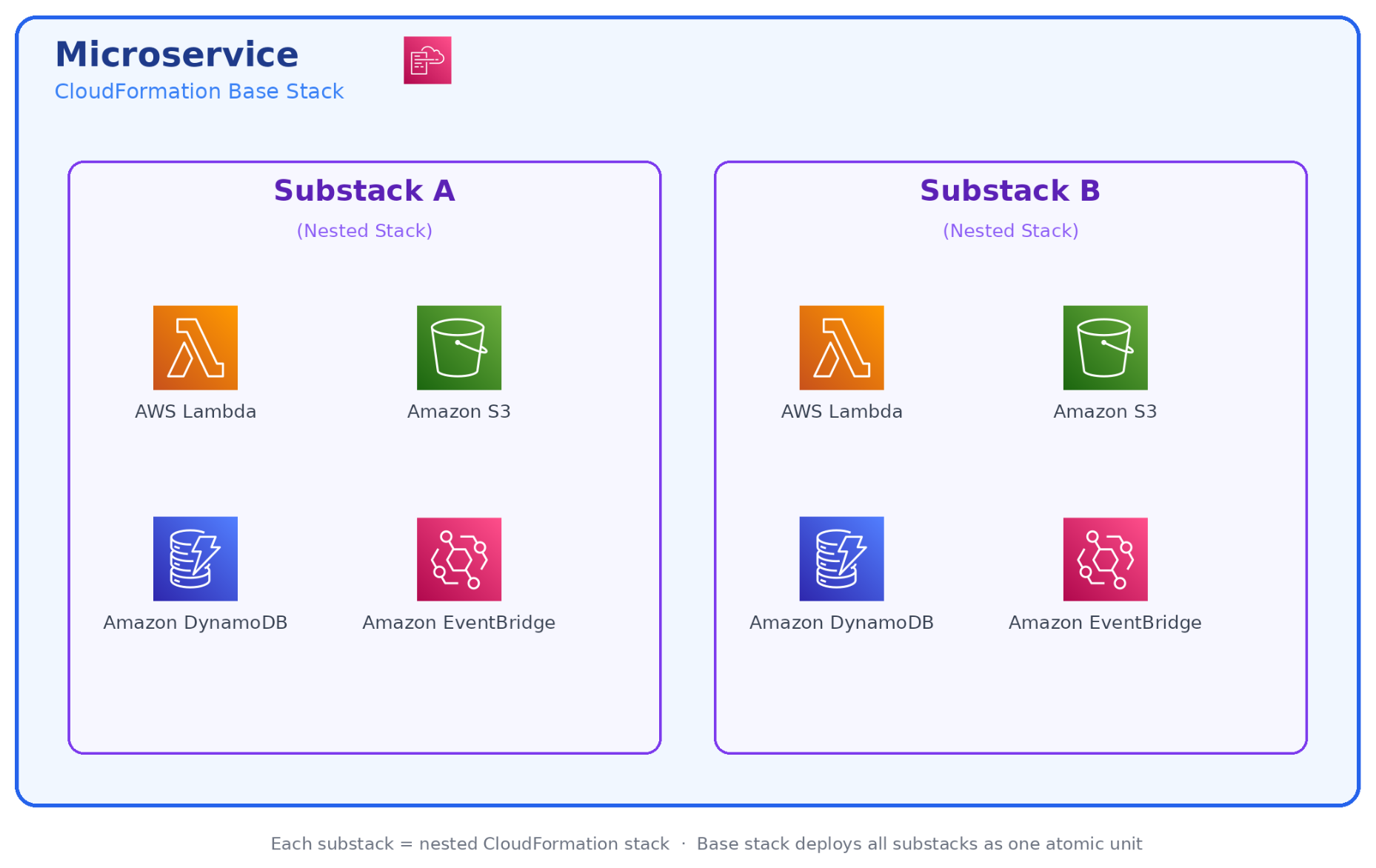
Each microservice in our platform follows a consistent structure: 5 to 15 Lambda functions coordinated by AWS Step Functions, with Amazon EventBridge handling event routing and Amazon DynamoDB as the primary data store.

Architecture diagram showing a microservice composition with Lambda functions, Step Functions, EventBridge, and DynamoDB

These resources are bundled together into a dedicated AWS CloudFormation stack for deployment.

As we onboarded our first handful of tenants, it quickly became clear that deploying and updating AWS CloudFormation stacks individually per account wouldn’t scale. We adopted AWS CloudFormation StackSets, which let us push infrastructure updates to multiple accounts in parallel from a central management account. At this stage, StackSets felt like a superpower. One deployment operation and many accounts are updated simultaneously. We evaluated building a fully custom replacement later, but ultimately concluded that the maintenance overhead wasn’t worth the marginal control gains and stayed with StackSets as our core mechanism.

Phase 2: The first 50 accounts

Growing to 50 tenant accounts forced us to confront problems that weren’t visible at single-digit scale. Three areas in particular required deliberate architectural decisions: observability, account provisioning, and quota isolation.

Automating account creation

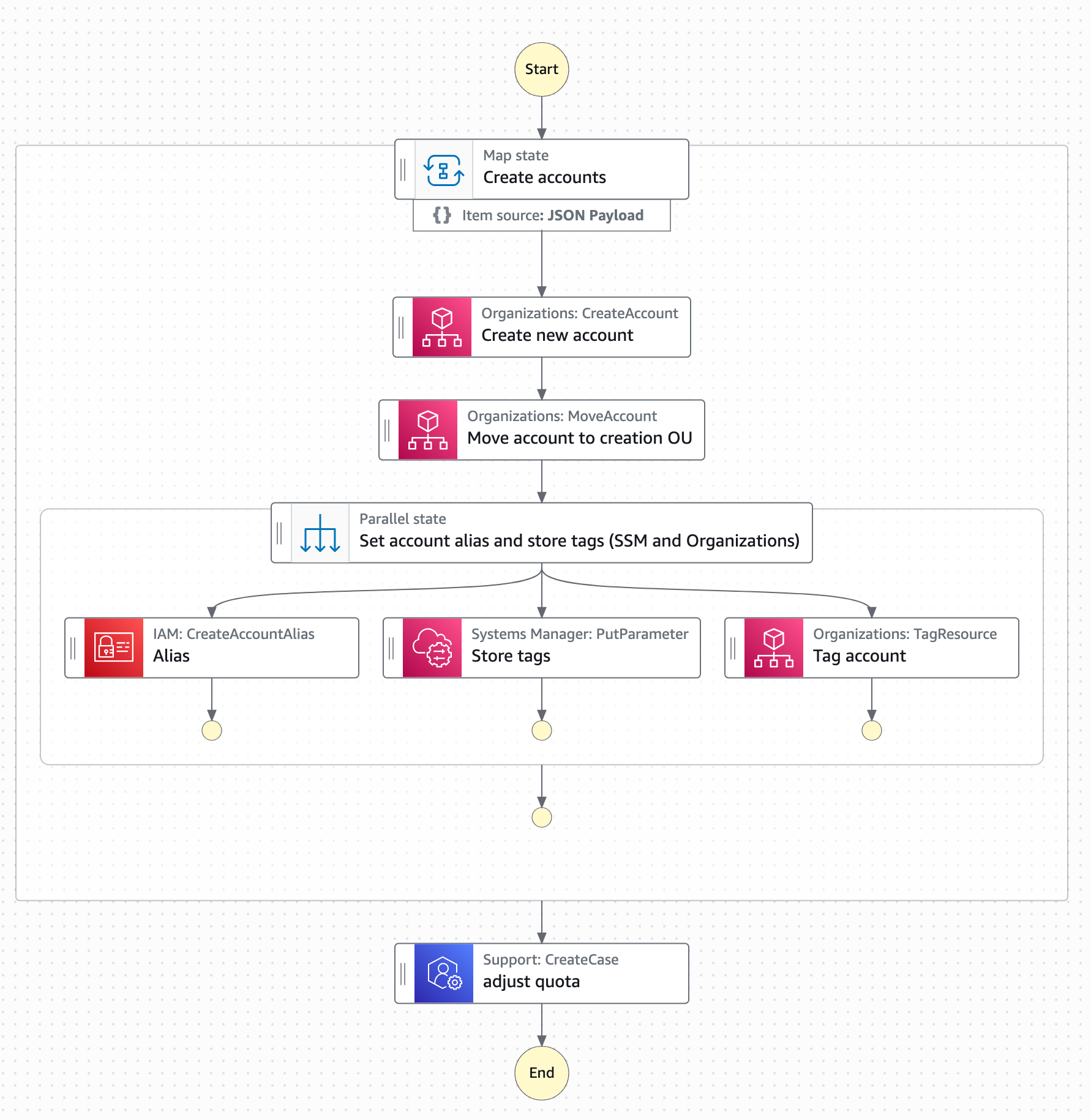
We knew manual provisioning would not scale. Instead we built an automated account factory on top of AWS Organizations: an AWS Step Functions workflow in the management account handles the full provisioning lifecycle: Creating the account, applying baseline service control policies (SCPs), bootstrapping cross-account IAM roles, and triggering the initial CloudFormation StackSet deployment. All done using cross-account AWS Lambda invocations. New tenant accounts go from request to ready in under 15 minutes, at near-zero incremental cost per provisioning run.

Account provisioning workflow using AWS Organizations and Step Functions

The quota isolation benefit

One underappreciated advantage of the account-per-tenant model is quota separation. Each account gets its own Lambda concurrent execution limit, its own Amazon API Gateway throttle, and its own service quotas across the board. In a shared-account SaaS model at this scale, a single noisy tenant could exhaust shared concurrency and cause cascading failures across all other tenants. With account isolation, that class of problem simply doesn’t exist as each tenant’s activity is bound to their own account.

Phase 3: Scaling challenges (the self-DDoS)

As our fleet grew beyond a few hundred accounts, we began to experience the “Physics of Scale”. We discovered that when hundreds of backend service instances simultaneously access other services, the resulting request volume can resemble a coordinated attack, impacting not only our own infrastructure but also AWS.

One time, we faced a massive metric spike where our own functions effectively overwhelmed (similar to a DDoS attack) our internal APIs. The root cause was synchronized schedules: every Lambda was using the same rate(5 minutes) expression, which aligned to the top of the minute across thousands of accounts.

The solution was request scattering. We now use a standardized internal library that enforces jitter, randomized batch offsets, and staggered updates across all scheduled functions.

Rule of Thumb: “Never do the same thing at the same time everywhere”.

Multi-account observability as a cost driver

With several dozen accounts, manual log access per account became unworkable. We adopted a third-party observability platform, forwarding Amazon CloudWatch logs and metrics cross-account to a centralized dashboard. At roughly $3 per account per month, the cost felt insignificant.

That assumption was soon replaced by a very real learning: at thousands of accounts, $3 per account per month becomes an impactful expense that demands active management. We learned to treat per-account observability costs with the same scrutiny you apply to compute costs.

What came as a surprise to us were the actual cost drivers: instead of Lambda compute or storage costs, we found that forwarding all observability data almost doubled our cloud bill. As a result, we had to learn how to differentiate between high and low priority observability data and only move around the priority data.

With all mitigations combined we managed to bring observability costs down to around $0.7 per account. Additionally, we were able to switch accounts to almost 0 after some time of inactivity by only monitoring a small set of very basic metrics.

Phase 4: Rethinking architectural patterns for scale-to-zero

One of the most painful lessons was realizing that traditional Amazon SQS “best practices” increased costs in our use-case and scale.

Replacing SQS and the DLQ dilemma

After we scaled to over a thousand AWS accounts, we understood that “idle” doesn’t necessarily mean there are no costs – even when using Serverless. When Lambda functions consume events from EventBridge through an SQS queue to increase resilience, they constantly make requests to the queue even when there are no messages to process.

To eliminate the cost of continuous polling, we removed Amazon SQS from the path between Amazon EventBridge and AWS Lambda.

  • Metric-Driven Safety: Instead of relying on a queue to buffer requests, we monitor AsyncEventsDropped and ConcurrentExecutions to make sure we stay within our quotas without losing events.
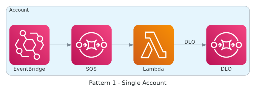
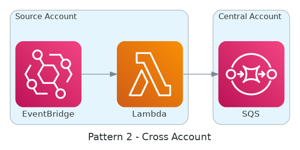
  • The Centralized DLQ: Polling individual Dead Letter Queues (DLQs) in every account reintroduced the same polling cost issues. We solved this by routing failures to a centralized DLQ as shown in the following two diagrams.
  • The Isolation Trade-off: This approach requires extreme discipline to make sure we don’t break our data isolation patterns, as events from different tenants converge in a single location for recovery. Because of cost implications at scale, the use of SQS moved from a silo to a bridged model where the AWS account ID can be treated as a tenant ID.

Individual dead letter queue per queue architecture

Individual DLQ per queue

Centralized dead letter queue polling architecture

Centralized DLQ polling

Phase 5: Industrializing the deployment engine

Serverless architectures grow to large numbers of infrastructure components: where a monolith or Amazon Elastic Compute Cloud (Amazon EC2)-based service might be a handful of resources, a single microservice in our stack spans dozens of Lambda functions, EventBridge rules, DynamoDB tables, and Step Functions state machines. Multiplied across thousands of accounts, deployment complexity compounds quickly.

Initially, we used AWS CloudFormation StackSets to roll out updates in parallel. However, at the scale of 1 million Lambda functions, StackSets hit a performance ceiling and occasionally produced errors that added up significantly at our volume.

From custom engines to collaborative roadmaps

The bottlenecks became such a blocker that we began building our own internal serverless deployment system to replace StackSets. This caught the attention of the AWS CloudFormation service team, who committed to supporting our use case at the scale we required and partnered with us closely from that point on.

By engaging early and often, we were able to:

  • Influence the Roadmap: We provided the scale requirements that helped AWS prioritize StackSet stability and performance improvements.
  • Automate Resiliency: We built a deployment tracking service that aggregates StackSet events through Amazon EventBridge. A central AWS Step Functions state machine now acts as our “single-pane-of-glass,” acting on failures and triggering retries for occasional AWS internal errors.

Phase 6: Mature governance and FinOps

Being able to scale a serverless platform with a small team of engineers requires consistent and efficient governance practices. This applies to both cloud governance topics as well as engineering practices. Otherwise it will be next to impossible to keep software delivery and development performance as well as reliability at a high level over time.

Cost optimization also changes at a higher maturity level: once cost control is tightly monitored and automated, the discipline changes from housekeeping tasks to collect easy cost savings towards increasingly complex architectural changes. For example, if a new feature significantly increases the number of Lambda invocations and drives up cost, you will need to re-think the architecture and include the new focus on cost.

The mono-repo strategy

We consolidated 20 microservices into a single mono-repo. This helped us to:

  • Enforce consistent tooling and security scanning across more than a million functions.
  • Coordinate runtime and library upgrades through a single source of truth for configuration.
  • Make sure every change passes through the same CI/CD chain with guaranteed compatibility.

The “Almost-Zero” Reality

Even with a scale-to-zero mandate, we learned that “zero” is often “almost-zero”.

  • The Monitoring Tax: We avoided services like NAT Gateways, but monitoring introduced additional costs such as CloudWatch Alarms. Aggregating metrics in external observability tools added up quickly.
  • The Optimization Payoff: By aggressively optimizing these costs, we reduced our idle cost for inactive accounts to less than $1 per month.

Think beyond the obvious services

One of the most valuable habits we built was resisting the urge to immediately default to a familiar pattern or write custom code. AWS offers a growing catalog of fully managed, event-driven services such as Amazon EventBridge Pipes, AWS AppSync, Amazon SQS FIFO, and others, that can remove entire categories of custom Lambda code. Before writing a function, ask whether a native service integration already solves the problem.

A deliberate research step of exploring native AWS capabilities before opening an editor consistently paid off. It reduces the surface area you own, eliminates maintenance burden, and builds the team’s instinct for choosing the right service over reinventing it. Serverlessland is an excellent starting point for discovering patterns and service combinations you may not have considered.

Conclusion: Scaling efficiency faster than growth

Scaling from 0 to 1M Lambda functions across thousands of AWS accounts is a question of efficiency not of capacity. Every new account, every new customer, adds potential operational load. The only way to stay ahead is to make sure efficiency scales faster than growth. For us, that means true scale-to-zero, proactive and efficient quota management, tight collaboration with AWS service teams, disciplined developer education, and a mono-repo that enforces consistency.

We’ve learned that the difference between success and failure at this scale lies in unexpected aspects like the hard-learned fact that observability becomes an increasingly complex problem the more distributed your platform becomes.

The benefits are substantial. With the right automation and architectural rigor, a lean team can operate a large-scale infrastructure. Using a cloud-native approach based on serverless services is the most important operational advantage in this case.

To apply these lessons to your own workloads, discover event-driven patterns and service combinations on Serverless Land.


About the authors

Optimize your Tableau integration with Amazon Redshift Serverless

Post Syndicated from Nidhi Nayak original https://aws.amazon.com/blogs/big-data/optimize-your-tableau-integration-with-amazon-redshift-serverless/

This is a guest blog post co-written by Adiascar Cisneros, from Tableau at Salesforce.

Integrating Tableau with Amazon Redshift Serverless gives you high-performance analytics with serverless scaling and minimal capacity planning. Although automatic scaling handles warehouse management for you, optimization requires a strategic approach to data modeling, security, and query management.

In this post, we provide a guide to help you use Tableau’s Relationships and Amazon Redshift Serverless architecture to deliver sub-second insights while maximizing every Redshift Processing Unit (RPU). We also provide guidance on five key areas: data model architecture for optimal query performance, security configuration and access control, performance optimization through smart configuration, cost management strategies, and query and join optimization techniques.

Prerequisites

Before implementing these optimization strategies, make sure you have:

  • Tableau Desktop (version 2022.1 or later) or Tableau Server deployed.
  • An active Amazon Redshift Serverless workspace.
  • AWS Identity and Access Management (IAM) permissions to configure authentication and access controls.
  • Network connectivity configured between your Tableau environment and Amazon Redshift Serverless.
  • The native Amazon Redshift driver installed.

Building the foundation

The success of any analytics system begins with its data model. True scalability starts with the end-user experience. Your data model is more than a storage structure. It’s the foundation of dashboard responsiveness. By aligning your database design in Amazon Redshift with your analytical requirements, you empower Tableau to generate highly efficient queries, reducing costs and keeping your users engaged with the data.

When connecting to Amazon Redshift, we recommend using Tableau’s logical data model, specifically Relationships. With Relationship, you can preserve the native level of detail for each table, so Tableau can perform join culling and dynamically query only the specific tables needed for a particular visualization.

When designing your Amazon Redshift schema, implement a well-structured star or snowflake schema, or one big denormalized table where appropriate. This allows Tableau to optimize query execution automatically. Modern Amazon Redshift deployments benefit significantly from Automatic Table Optimization (ATO), which uses AI and machine learning (ML) to continuously monitor and adjust sort keys and distribution keys. To take advantage of ATO, keep sort keys and distribution styles at their default AUTO setting when you create tables. ATO then continuously monitors workload patterns and adjusts keys to improve query performance.

Start by implementing Relationships in your existing workbooks to take advantage of join culling and improved query performance.

Securing your connection

Native database drivers provide enhanced security features and better integration with Amazon Redshift capabilities compared to generic ODBC or JDBC alternatives.

The integrity of your analytics relies on the quality of the connection between your platforms. Use the native Amazon Redshift driver rather than generic ODBC or JDBC alternatives. The native driver is specifically engineered to use the advanced capabilities of Amazon Redshift and supports modern security protocols, such as AWS IAM Identity Center, out of the box. By prioritizing the native driver, you verify that your connection uses the latest security patches and performance optimizations, establishing a hardened and efficient entry point for your data. For more information, see Integrate Tableau and Okta with Amazon Redshift using AWS IAM Identity Center.

Connection stability for high-scale environments

In Amazon Redshift, cursors are used to retrieve a result set from a query and process the data row-by-row or in smaller chunks rather than loading the entire set into memory at once. For high-scale environments, stable connections depend on how you handle large result sets. In some high-volume scenarios, Amazon Redshift cursors can introduce resource overhead that impacts user concurrency. Monitor your workload and, if necessary, fine-tune your connection configurations using Tableau Data Customization (TDC) files. TDC files are XML configuration files that customize how Tableau connects to your database. Specifically, validate whether disabling cursors improves throughput.

Important: This configuration loads the entire dataset into memory. For large datasets, this might cause performance degradation or out-of-memory errors. Evaluate your dataset size and business requirements before you turn on this setting. This is a key step in tuning your deployment, helping verify that your Amazon Redshift resources remain available and responsive for secure, ad-hoc analysis.

Security best practices

Follow security best practices while deploying Amazon Redshift Serverless. Configure security groups to control inbound access from Tableau Server and Desktop IP ranges. IAM authentication must be the primary method, complemented by SSL/TLS encryption for all connections.

Role-based access control (RBAC) forms the backbone of your security framework:

For authorization, implement a layered security model:

  • Apply explicit GRANT statements.
  • Create distinct database roles aligned with business functions.
  • Use Amazon Redshift system-defined roles judiciously.
  • Apply dynamic data masking for sensitive data.
  • Conduct regular security audits to support ongoing protection.

Audit your current connection types and migrate to the native Amazon Redshift driver if you’re using ODBC or JDBC connections.

Enhancing performance through smart configuration

Smart configuration spans how much data you query, where you push complex logic, how you design dashboards, and how you tune connections. The following sections cover each area.

Managing data volume

To maximize workbook efficiency, start by rigorously managing your data volume. Although Amazon Redshift handles large datasets well, your dashboard should query only what is strictly necessary. Use Tableau Hyper Extracts for production environments to provide a consistent, high-speed cache that offloads repetitive query processing from Amazon Redshift. If a live connection is required, strictly limit your data intake by using Data Source Filters and hiding all unused fields. This helps verify that Tableau generates leaner queries, significantly reducing network latency and processing time.
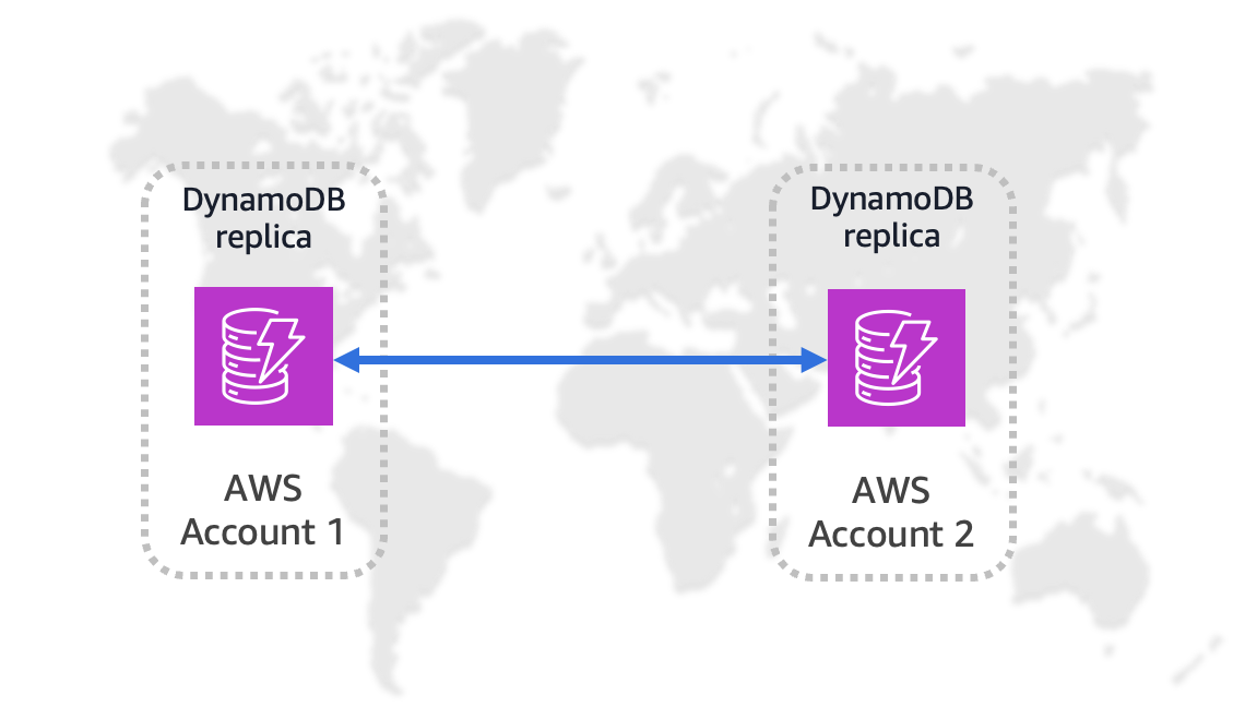
Shifting complexity to the database

Next, shift the burden of complexity away from the visualization layer. Materialize calculations within your extracts or push complex logic (especially row-level string manipulations and regex) directly down to the Amazon Redshift database level. By pre-calculating these values before the user ever loads the dashboard, you eliminate expensive runtime processing.

Simplify your logic within Tableau by using native features like CASE statements or Sets rather than complex IF/THEN statements. Testing shows these methods perform significantly faster for grouping dimensions.

Streamlining dashboard design

Additionally, optimize the rendering process by streamlining your dashboard design:

  • Limit the number of visualizations per dashboard.
  • Prioritize fixed-size dashboards to maximize server-side caching effectiveness.
  • Avoid high-cardinality filters (fields with thousands of unique values).
  • Don’t use the ‘Show Only Relevant Values’ setting on large datasets, because it forces the system to run extra background queries that slow down your dashboard.

Connection and parameter tuning

Optimize Tableau’s performance by enabling connection pooling tailored to your concurrent user count. Configure datetime handling and parallel query execution settings to match your workload patterns.

You can enhance the automatic resource management of Amazon Redshift Serverless through parameter optimization. Key parameters include:

Choosing between extracts and live queries is a foundational architectural decision. We recommend a hybrid approach tailored to specific use cases rather than a one-size-fits-all policy.

When to use live queries

Live queries are best for real-time analytics. They use Amazon Redshift Serverless automatic scaling to query massive datasets in place. Use this approach for:

  • Up-to-the-minute data requirements.
  • Datasets too massive for extracts.
  • Scenarios requiring database-level row security.
  • Integration with Amazon Redshift Spectrum for Amazon Simple Storage Service (Amazon S3) data.

Keep in mind that live connections rely entirely on the database’s performance, so optimizing your Amazon Redshift tables and using materialization techniques within the database is important for maintaining interactivity.

When to use extracts

For scenarios when data is static or where query performance is critical, Tableau Hyper Extracts provide a high-speed cache that shifts the processing load from Amazon Redshift to Tableau’s data engine. This is valuable for dashboards with complex calculations (such as row-level string manipulations or heavy aggregations) where an extract can pre-materialize results, effectively baking in the logic before the user ever loads the view. By using extracts for these heavy workloads, you reduce the compute load on Amazon Redshift, lowering costs while delivering sub-second response times to end users.

Right-sizing your extracts

To maximize efficiency, right-size your extracts for your dashboard’s specific needs:

  • Avoid the SELECT * mentality.
  • Use data source filters to limit rows.
  • Hide unused fields to remove redundant columns.
  • For higher-level analysis, aggregate your data during the extract process. For example, summarize daily transactions into monthly trends to significantly reduce file size and query time.
  • Schedule refreshes during off-peak hours.
  • Use incremental updates to add only new rows, minimizing Amazon Redshift RPU usage and network overhead.

Balance performance and cost by aligning your connection choice with business freshness requirements and data complexity. Monitor usage patterns to refine this balance over time.

Star schema query and join optimization

Optimize your star schema joins and queries to reduce execution time and compute costs by using Tableau Relationships. Relationships keep tables separate, allowing Tableau to automatically query only the necessary tables for the fields in the view. Relationships are more flexible and often perform better than joins because they don’t force a row-level merge on all fields.

Inefficient joins and poorly optimized queries force Amazon Redshift to scan unnecessary data, increasing both query execution time and compute costs.

Query optimization best practices

Avoid Custom SQL, which forces Tableau to wrap queries in complex sub-selects. Instead, connect directly to tables or views to let the database optimizer function effectively.

Define primary and foreign keys in your Amazon Redshift schema to allow Tableau to assume referential integrity.

Important: Amazon Redshift does not enforce primary or foreign key constraints. They are informational only, and the query optimizer uses them to generate more efficient execution plans. You’re responsible for data integrity at the application or ETL layer. For more information, see Defining constraints. Assume Referential Integrity is a Tableau setting that tells the engine to trust defined key relationships without validating them at query time, reducing query complexity.

Use Materialized Views to pre-compute heavy aggregations, which reduces execution time for frequently accessed data patterns. For example, create materialized views for common date-based aggregations or customer-level summaries.

Optimize Amazon Redshift Serverless by denormalizing data to minimize complex joins. After you apply these changes, use Tableau’s Performance Recorder to regularly validate your query speeds and identify bottlenecks.

Cost optimization and monitoring

Amazon Redshift Serverless charges in RPU-hours on a per-second basis (60-second minimum), so you only pay for the workloads you run.

Optimizing query volumes and resource usage helps you control Amazon Redshift Serverless costs and maintain predictable spending. To help control compute costs, optimize Tableau queries before they reach Amazon Redshift by using Data Source Filters and ‘Hide All Unused Fields.’ This forces the generation of lean SELECT statements that scan only the necessary rows and columns. Because Amazon Redshift Serverless scales resources based on workload, reducing data volume and complexity at the Tableau source layer can help lower RPU consumption and costs.

For more information, see Amazon Redshift Serverless billing.

Using extracts as a cost buffer

Tableau Hyper Extracts act as a cost buffer for high-traffic dashboards. By extracting data into Tableau’s in-memory engine, database costs are typically incurred during scheduled refreshes rather than for every individual user interaction. For live connections, maximize Tableau’s caching architecture by setting server cache policies to “Refresh less often,” ensuring that repetitive dashboard views are served instantly from memory and avoid redundant, billable queries.

Monitoring and alerting

Monitor RPU usage patterns and set billing alerts to maintain cost control:

  • Combine query result caching with strategic scheduling for resource-intensive tasks.
  • Use scaling event data and query patterns to define thresholds.
  • Set up Amazon CloudWatch alarms for RPU consumption spikes.
  • Review Amazon Redshift query monitoring metrics weekly to identify optimization opportunities.

Clean up

To avoid incurring ongoing charges, delete the resources you created while testing the configurations described in this post.

  • Delete the Amazon Redshift Serverless workgroup and namespace if they were created for testing.
  • Remove any IAM roles, policies, and users created specifically for Tableau connectivity.
  • Delete security groups configured for Tableau Server or Desktop IP access.
  • Remove any materialized views, tables, or schemas created during testing.
  • Cancel any scheduled Tableau extract refreshes connected to test workgroups.
  • Delete Tableau data sources and workbooks that reference test environments.
  • Remove any CloudWatch alarms or CloudTrail configurations set up for monitoring test resources.

For more information about managing Amazon Redshift Serverless resources, see Billing for Amazon Redshift Serverless.

Conclusion

This post covered key optimization strategies for Tableau and Amazon Redshift Serverless integration: data model architecture using Relationships, security configuration with native drivers and AWS IAM, performance optimization through extracts and smart configuration, cost management with RPU monitoring, and query optimization techniques.

As AI-driven optimization evolves, staying informed about Amazon Redshift AI features and best practices, including Tableau Pulse, is key. Regularly review your configuration, performance, and security to verify that your Tableau and Amazon Redshift Serverless integration remains secure, cost-effective, and high-performing.

Optimization is an ongoing, iterative process. To keep your environment optimized, regularly review your settings, monitor performance, and adapt as workload patterns evolve. This approach maintains a cost-effective analytics environment that scales with your organization.

Ready to build a secure, high-performance analytics solution that delivers both speed and cost efficiency? Visit the Salesforce and AWS partnership webpage to start scaling your insights today.


About the authors

Nidhi Nayak

Nidhi Nayak

Nidhi is a Senior Technical Account Manager with AWS, she helps enterprise customers build scalable, high-performance cloud applications and optimize cloud operations. With over a decade of experience in Data Analytics, Nidhi currently focuses on Redshift & Generative AI integration with Redshift.

Nita Shah

Nita Shah

Nita is a Sr. Analytics Specialist Solutions Architect at AWS based out of New York. She has been building enterprise data platforms, data warehousing, and analytics solutions for over 20 years and specializes in Amazon Redshift. She is focused on helping customers design and build enterprise-scale well-architected analytics and decision support platforms

Bill Tarr

Bill Tarr

Bill is a Principal Partner Solutions Architect at AWS, specializing in Business Applications including Salesforce, MuleSoft, and agentic AI interoperability. From software builder to architect, he has 20+ years of experience shaping SaaS technology strategies from startup to enterprise. Bill has delivered 12+ sessions at AWS re:Invent and produced 71 episodes of “Building SaaS on AWS.

Adiascar Cisneros

Adiascar Cisneros

Adiascar is a Tableau at Salesforce Sr. Product Manager. Adiascar manages the Tableau technical relationship with Amazon Web Services, coordinating roadmap prioritization, connector improvements, customer events, and publications. Adiascar joined Tableau in 2018 and is based in Atlanta GA.

Run isolated sandboxes with full lifecycle control: AWS Lambda introduces MicroVMs

Post Syndicated from Micah Walter original https://aws.amazon.com/blogs/aws/run-isolated-sandboxes-with-full-lifecycle-control-aws-lambda-introduces-microvms/

Today, we are announcing AWS Lambda MicroVMs, a new serverless compute primitive within AWS Lambda that lets you run code generated by users or AI in isolated, stateful execution environments. You get virtual machine level isolation, near-instant launch and resume, and direct control over environment lifecycle and state, all without managing infrastructure or building expertise in complex virtualization technologies. Lambda MicroVMs are powered by Firecracker, the same lightweight virtualization technology that has powered over 15 trillions of monthly Lambda function invocations.

Why customers need this
Over the past few years a new class of multi-tenant applications has emerged that all share the need to hand each end user their own dedicated execution environment in which to safely run code that the application developer did not write. AI coding assistants, interactive code environments, data analytics platforms, vulnerability scanners, and game servers that run user-supplied scripts all fit this pattern. Building that capability today means making a difficult choice. Virtual machines deliver strong isolation but take minutes to start. Containers launch in seconds, yet their shared-kernel architecture requires significant custom hardening to safely contain untrusted code. Functions as a service are optimized for event-driven, request-response workloads, but are not designed for long-running interactive sessions that need to retain environment state across user interactions. That leaves developers either accepting tradeoffs between performance and isolation, or investing significant engineering resources to build and operate custom virtualization infrastructure to achieve isolated execution while delivering low-latency experiences to end-users. This presents an effort that demands deep expertise and pulls engineering time away from the product they are actually trying to build.

Lambda MicroVMs is purpose-built for exactly this gap. Each MicroVM gives a single end user or session its own isolated environment that launches rapidly, retains memory and disk state for the length of the session, and pauses to a low idle cost when the user steps away. Because the same Firecracker technology already underpins AWS Lambda Functions, you inherit the operational maturity of a service that has been running this stack at scale.

Let’s try it out
To get started, I navigated to the AWS Lambda console, where Lambda MicroVMs now appears in the left-hand navigation menu. I first need to create a MicroVM Image.

I packaged a Flask web app and its Dockerfile into a zip file, uploaded it to an Amazon Simple Storage Service (Amazon S3) bucket.

My Flask API – app.py

import logging

from flask import Flask, jsonify

app = Flask(__name__)
logging.basicConfig(level=logging.INFO)


@app.route("/")
def hello():
    app.logger.info("Received request to hello world endpoint")
    return jsonify(message="Hello, World!")


if __name__ == "__main__":
    app.run(host="0.0.0.0", port=5000)

My Dockerfile


FROM public.ecr.aws/lambda/microvms:al2023-minimal
RUN dnf install -y python3 python3-pip && dnf clean all

WORKDIR /app

COPY requirements.txt .
RUN pip install --no-cache-dir -r requirements.txt

COPY app.py .

EXPOSE 5000

CMD ["gunicorn", "--bind", "0.0.0.0:5000", "app:app"]

I used the following command to create my MicroVM Image.

aws lambda-microvms create-microvm-image \
--code-artifact uri=<path/to/s3/artifact.zip> --name <VM_image_name> \
--base-image-arn arn:aws:lambda:us-east-1:aws:microvm-image:al2023-1 \
--build-role-arn <IAM role ARN>

You can also create the MicroVM Image in the AWS Console as in the image above. Once I ran the command, Lambda retrieved the zip, ran the Dockerfile, initialized the application, and took a Firecracker snapshot of the running disk and memory state. Build logs streamed in real time to Amazon CloudWatch under /aws/lambda/microvms/<image-name>, and when the image was ready it appeared in the console with its Amazon Resource Name (ARN) and version number.

aws lambda-microvms run-microvm \
--image-identifier arn:aws:lambda:<region>:<acct>:microvm-image:my-image \
--execution-role-arn arn:aws:iam::<acct>:role/MicroVMExecutionRole \
--idle-policy '{"maxIdleDurationSeconds":900,"suspendedDurationSeconds":300,"autoResumeEnabled":true}'

Launching can also be done via the AWS Console or the CLI. I passed the image ARN and an idle policy configured to auto-suspend after 15 minutes of inactivity and auto-resume on the next incoming request. No networking setup was required. Lambda assigned the MicroVM a unique ID, returned a dedicated endpoint URL, and started a new MicroVM with my Flask app already running, since it was resumed from a snapshot. My Flask app was already running the moment the launch completed. One API call to get a fully initialized, bootstrapped compute environment.

To send traffic, I generated a short-lived auth token with the CLI and attached it to a plain HTTPS request using the X-aws-proxy-auth header. The request landed on my Flask app immediately. I then let the MicroVM sit idle past the suspend threshold, at which point the MicroVM was suspended, with its memory and disk state snapshotted and stored. I then sent another request, and it resumed with the application state fully intact. From the client side, the pause never happened.

How it works
Under the covers, Lambda MicroVMs delivers three capabilities that, until today, no single AWS compute service offered together. The first is virtual machine level isolation, which comes from Firecracker. Each session runs in its own dedicated MicroVM with no shared kernel and no shared resources between users, so untrusted code supplied by one user is contained to their execution environment, without access to other environments or the underlying system. The second is rapid launch and resume. The model is image-then-launch: you create a MicroVM Image by supplying a Dockerfile and code packaged as a zip artifact in Amazon S3, and Lambda runs your Dockerfile, initializes your application, and takes a Firecracker snapshot of the running environment’s memory and disk state. Every subsequent MicroVM launched from that image resumes from the pre-initialized snapshot rather than booting cold, which means launches and idle resumes both achieve near-instant startup latency. Even a multi-gigabyte interactive session comes back online quickly enough to feel responsive to the end user. The third is stateful execution. A running MicroVM retains memory, disk, and running processes across the user’s session. During idle periods, a MicroVM can be suspended – with memory and disk state intact – and resumed when traffic arrives. Installed packages, loaded models, and working filesets are readily available when the user resumes their session. MicroVMs support up to 8 hours of total runtime and can be suspended automatically after a configurable idle window, which makes it straightforward to build products as varied as software vulnerability scans that complete in minutes, data analytics applications that run for hours, and interactive coding sessions with extended idle periods. As Lambda MicroVMs are started from pre-initialized snapshots, applications generating unique content, establishing network connections, or loading ephemeral data during initialization may need to integrate with service-provided hooks for compatibility.

Lambda MicroVMs is a new resource within AWS Lambda, with a distinct API surface. Lambda Functions remain the right choice for event-driven, request-response workloads, and Lambda MicroVMs is purpose-built for multi-tenant applications that need to hand each end user or session their own isolated environment to execute user- or AI-generated code. The two complement each other. An application using Lambda Functions for its event-driven backbone can call into Lambda MicroVMs for the steps that need to run untrusted code in isolation. You bring the application, and the service delivers the execution environment.

Now available
AWS Lambda MicroVMs is available today in the US East (N. Virginia, Ohio), US West (Oregon), Europe (Ireland) and Asia Pacific (Tokyo) Regions, on the ARM64 architecture, with up to 16 vCPUs, 32 GB of memory, and 32 GB of disk per MicroVM. Idle MicroVMs can be suspended explicitly through an API call or automatically through a lifecycle policy, which reduces the running cost while preserving full state for fast resume. Pricing details can be found on the AWS Lambda pricing page.

To get started, visit the AWS Lambda console, or learn more on the Lambda MicroVMs product page. For documentation, see the Lambda MicroVMs Developer Guide.

Announcing Spark Connect on Amazon EMR Serverless: Interactive PySpark development, anywhere

Post Syndicated from Al MS original https://aws.amazon.com/blogs/big-data/announcing-spark-connect-on-amazon-emr-serverless-interactive-pyspark-development-anywhere/

Today, AWS is announcing support for Spark Connect on Amazon EMR Serverless with EMR release 7.13 (Apache Spark 3.5.6) and later versions. You can now build and debug Spark applications from your preferred local environment while running full-scale Spark operations on EMR Serverless.

Previously, code that worked on a local machine might break in production because of environment mismatches, dependency conflicts, or unexpected data patterns. The only way to catch it was a deploy-and-check cycle. With the Spark Connect feature, you can develop Spark code from a supported local environment, such as an IDE (for example, VS Code or PyCharm), Jupyter notebooks, Amazon SageMaker Unified Studio (SMUS) Data Notebooks, Amazon Q Developer, or Kiro. There are no clusters to provision, no code to repackage, and no deploy-and-check loop. Your local Python session can stay local as usual while Spark operations are automatically routed to a remote Spark server for execution.

Each Spark Connect session has its own AWS resource with a unique ARN, enabling per‑session AWS Identity and Access Management (AWS IAM) permissions, tag‑based cost allocation, audit through AWS CloudTrail, and session-specific configuration overrides. This gives teams finer control over who runs what, at what cost. You also get real-time visibility through the Spark UI, persistent session history, and a dedicated interface to monitor and manage active and completed sessions.

For more details, visit the EMR Serverless release notes or the EMR Serverless Developer Guide. For a quick look at the experience, here’s a demonstration of using Spark Connect in Amazon SageMaker Unified Studio Data Notebooks:

For a runnable end-to-end example, try the EMR Serverless Spark Connect sample notebook from your local IDE. See the following demonstration:

How Spark Connect works

Spark Connect uses a client-server architecture that separates application code from the Spark engine. The client, a lightweight PySpark library running on a local environment, sends Spark operations over a secure gRPC/TLS connection to a Spark Connect server running on EMR Serverless. Then the server runs that Spark code on EMR Serverless as compute. Finally, it returns results to your local session.

Spark Connect client-server architecture showing a local IDE connecting to a Spark Connect server on EMR Serverless

Your local machine doesn’t need Spark installed, doesn’t need direct access to the data, and doesn’t need to be sized for the workload. Because the client is a compact library, you can embed Spark operations in your Python applications that support PySpark. This includes web services, dashboards, and automation scripts. For example, a development team can add Spark-powered analytics directly into a FastAPI backend or a Streamlit dashboard, treating Spark like a database driver rather than a separate batch system. These capabilities extend Spark Connect use cases beyond traditional notebook and IDE development, since the compute-intensive processing happens on the server – EMR Serverless side. This allows you to use pandas, matplotlib, and your team’s internal Python libraries on your laptop or in your embedded clients, without installing those libraries on EMR Serverless.

With Spark Connect server sessions running on EMR Serverless, you pay for compute only while your session is active. When inactive, you’re not paying. EMR Serverless automatically scales compute up and down based on workload demands through dynamic resource allocation (DRA), eliminating the need to predict capacity ahead of time. For teams that run Spark Connect sessions regularly, you can configure pre-initialized capacity on your EMR Serverless application for faster session startup times. Additionally, your Spark Connect sessions have access to the full suite of EMR Serverless features, including AWS Graviton processors for cost optimization and secure VPC connectivity to your data sources. You also get access to custom images with flexibility and integrated observability through Amazon CloudWatch and the Spark UI.

Getting started

Getting started with Spark Connect on EMR Serverless takes three steps: create an application, start a session, and connect from your IDE.

Note: The resources created in this quick start incur charges while active. Make sure to follow the cleanup steps at the end of this tutorial to avoid ongoing charges.

Prerequisites

  • In addition to the required job runtime IAM role, these additional permissions are needed: emr-serverless:StartSession, GetSession, GetSessionEndpoint, TerminateSession, GetResourceDashboard, and iam:PassRole on the runtime role.
  • An existing EMR Serverless application running emr-7.13.0 or later, with interactiveConfiguration.sessionEnabled = true.
  • boto3 version 1.43.0 or later to access the latest EMR Serverless session APIs.

Step 1: Create an EMR Serverless application with Spark Connect enabled

Amazon EMR Serverless application creation page in the EMR console

  • Open the Amazon EMR console and navigate to EMR Serverless.
  • Choose Get started. A pop-up appears. Choose Create and launch EMR Studio.
  • This takes you to the Create application page.
  • Enter a Name for your application (for example, spark-connect-app).
  • For Type, select Spark.
  • For Release version, select emr-7.13.0 or later.
  • For Architecture, choose x86_64 (default). This is compatible with most third-party tools and libraries.
  • Under Application setup options, select Use default settings for interactive workloads. This automatically sets interactiveConfiguration.sessionEnabled = true.
  • Choose Create and start application.

Alternatively, using the CLI command:

# Create an application with Spark Connect enabled
APP_ID=$(aws emr-serverless create-application \
  --type "SPARK" \
  --name "spark-connect-app" \
  --release-label emr-7.13.0 \
  --interactive-configuration '{"sessionEnabled": true}' \
  --query 'applicationId' \
  --output text)
echo "Created application: $APP_ID"
# Start the application
aws emr-serverless start-application --application-id "$APP_ID"

Step 2: Start a session

Next, start a session and obtain the Spark Connect endpoint.

Provide an IAM execution role that grants the session access to your data, such as reading data from an Amazon S3 bucket or querying the AWS Glue Data Catalog. This is the same type of role used for EMR Serverless batch jobs.

# Start a session with your execution role
$ROLE_ARN="YOUR_ROLE" # example: arn:aws:iam::123456789012:role/EMRServerlessSessionRole
SESSION_ID=$(aws emr-serverless start-session \
  --application-id $APP_ID \
  --execution-role-arn $ROLE_ARN \
  --query sessionId \
  --output text)

# Get the session endpoint
aws emr-serverless get-session-endpoint \
  --application-id $APP_ID \
  --session-id $SESSION_ID

The get-session-endpoint response includes a secure endpoint URL and an authentication token. All communication between your local environment and EMR Serverless is encrypted using TLS. Treat the token as a sensitive credential. Consider using AWS Secrets Manager to store and retrieve tokens programmatically. The authentication token is time-limited to 1 hour, so for long-running sessions we recommend that you refresh it periodically.

Step 3: Connect from your local IDE

Use the returned endpoint URL and authentication token to connect to the Spark Connect server.

The connection URL uses the sc:// protocol, which is the Spark Connect standard. The use_ssl=true parameter supports encrypted communications over TLS, so your data and credentials are protected in transit.

from pyspark.sql import SparkSession

# Use the endpoint and auth token from get-session-endpoint
session_endpoint="<endpoint-from-get-session-endpoint>"
auth_token="<authToken-from-get-session-endpoint>"

spark_connect_url = (
    f"sc://{session_endpoint}:443/;use_ssl=true;x-aws-proxy-auth={auth_token}"
)

spark = SparkSession.builder \
    .remote(spark_connect_url) \
    .getOrCreate()

# Query data in your S3 data lake
df = spark.sql("SELECT * FROM my_catalog.my_database.my_table")
df.show()

# Run transformations at scale
df.groupBy("category").count().orderBy("count", ascending=False).show()
spark.stop()

Once connected, Spark operations you write in your IDE can be run on EMR Serverless. For debugging, you can pause the execution at breakpoints, inspect variables, and step through your transformations locally while EMR Serverless processes your data on remote, scalable infrastructure.

Sessions remain active for a configurable idle timeout (1 hour by default). If your connection drops, the session continues running, allowing you to reconnect without losing your work. You can also access the live Spark UI through the GetResourceDashboard API to monitor queries, stages, and executors in real time. After the session ends, the Spark History Server remains available for post-run analysis.

Clean up resources

If the 1-hour session idle timeout does not meet your needs, you can manually remove sessions to avoid ongoing costs. Note that terminating an active session will immediately stop you running Spark operations. Before doing that, verify all your critical data processing is completed, and results are saved.

# 1. Stop the active session
aws emr-serverless terminate-session \
  --application-id $APP_ID \
  --session-id $SESSION_ID

# 2. Stop the application
aws emr-serverless stop-application --application-id $APP_ID

Use cases

Spark Connect on EMR Serverless supports a wide range of development workflows. The following are some of the most popular use cases, including but not limited to:

  • Interactive ETL development — Build and test data pipelines interactively, validating transformations against full-scale datasets before promoting them to production as batch jobs.
  • SageMaker Unified Studio (SMUS) Data Notebooks — Run interactive PySpark sessions directly from SMUS Data Notebooks connected to EMR Serverless through Spark Connect.
  • Direct S3 and JDBC access without a catalog — Connect directly to S3 files and JDBC data sources without needing a metastore or catalog configuration.
  • Apache Iceberg Data Lakehouse analytics — Query and manage Iceberg tables through the AWS Glue Data Catalog, with full support for time travel, schema evolution, and partition management.
  • Amazon S3 Tables with federated catalog — Access S3 Tables as a federated Glue Data Catalog source, combining Iceberg features with serverless Spark execution.
  • dbt-spark — Run dbt-spark adapter against EMR Serverless via Spark Connect, allowing analytics engineers to develop and test transformations locally with dbt framework while using EMR Serverless as the remote Spark engine.
  • Exploratory data analysis and feature engineering — Analyze production-scale data from your preferred notebook environment instead of using sampled subsets, helping you catch data quality issues earlier.
  • Compute standardization — Standardize EMR Serverless as the Spark backend while giving you the flexibility to use preferred local tools, version control, and CI/CD workflows.

These use cases work across multiple client surfaces: IDEs, Jupyter notebooks, dbt-spark, and AI coding agents. Because Spark Connect is an open Apache Spark standard, the same PySpark code typically works across different Spark backends by changing the connection endpoint.

Availability and pricing

Spark Connect on EMR Serverless is now available with Apache Spark 3.5.6 on Amazon EMR release 7.13 and higher in all AWS Regions where EMR Serverless is available. There is no additional charge for using Spark Connect. You pay for the EMR Serverless compute resources (vCPU, memory, and storage) consumed during your session, the same pricing model as EMR Serverless batch jobs.

Conclusion

Spark Connect on EMR Serverless bridges the gap between local development and production-scale execution. Build and debug PySpark applications from your preferred environment (IDE, notebook, dbt, or AI coding agent) while EMR Serverless handles automatic scaling, per-session cost visibility, and infrastructure management behind the scenes. With ARN-addressable sessions, fine-grained IAM permissions, tag-based cost allocation, and per-session configuration overrides, your team gets the controls they need without sacrificing flexibility.

Get started today with EMR release 7.13.0 (Spark 3.5.6). Follow the step-by-step tutorial in the EMR Serverless Developer Guide to create your first Spark Connect session and experience interactive, serverless PySpark development firsthand.


About the authors

Al MS

Al MS

Al is a product manager for Amazon EMR at AWS.

Melody Yang

Melody Yang

Melody Yang is a Principal Analytics Specialist Solution Architect at AWS with expertise in Big Data technologies. She is an experienced analytics leader working with AWS customers to provide best practice guidance and technical advice in order to assist their success in data transformation. Her areas of interests are open-source frameworks and automation, data engineering and DataOps.

KiKi Nwangwu

KiKi Nwangwu

Kiki is an Analytics and GenAI Specialist Solutions Architect at AWS. She specializes in helping customers architect, build, and modernize scalable data analytics and generative AI solutions. She enjoys traveling and exploring new cultures.

Build stateful streaming applications with Apache Spark 4.0 on Amazon EMR Serverless

Post Syndicated from Raj Ramasubbu original https://aws.amazon.com/blogs/big-data/build-stateful-streaming-applications-with-apache-spark-4-0-on-amazon-emr-serverless/

Apache Spark 4.0 represents a major milestone in stream processing, introducing new capabilities that fundamentally change how developers build stateful streaming applications. At the heart of these improvements is the transformWithState API – a new capability that enables first-class support for timers, automatic state management, and schema evolution to Spark Structured Streaming.

With Spark 4.0 now available on Amazon EMR Serverless, developers can build stateful streaming applications using the transformWithState API in a fully managed, serverless environment that automatically scales based on workload demands. This combination delivers the power of sophisticated stream processing without the operational overhead of cluster management.

In this post, we demonstrate how to build a production-ready IoT device monitoring system using Spark 4.0’s transformWithState API on Amazon EMR Serverless. This example showcases the key capabilities of stateful streaming and provides a template you can adapt for your own use cases.

Apache Spark 4.0: introducing transformWithState

Apache Spark 4.0’s latest streaming features solve common production challenges in stateful applications by introducing native timer support and advance state management capabilities for complex event processing workflows. The new transformWithState API provides:

Key features of transformWithState

  • Native timer support: Register timers that fire callbacks at specific times for use cases like heartbeat monitoring, session timeout detection, and SLA violation alerts.
  • Automatic state TTL (Time-To-Live): Configure automatic expiration policies to prevent state from growing indefinitely. This is useful for use cases like session state size control, clearing stale device telemetry, maintaining a recency cache, or tracking invalid logins within the last hour for fraud detection.
  • Schema evolution: Evolve state schema without restarting from a new checkpoint. Add optional fields, remove fields, or widen numeric types. This is particularly valuable for use cases where data structures are dynamic, and application downtime for schema migration is not acceptable, enabling more resilient and flexible real-time streaming applications.
  • Multiple state variables: Support for multiple independent state variables (ValueState, ListState, MapState) per key, well-suited for building complex, real-time applications that require sophisticated state management, such as storing a history of recent error codes, tracking counts of various alert types, or maintaining multiple dimensions of user activity within a single stateful operator.
  • State observability: Query application state mid-stream using the State Data Source Reader for debugging and monitoring. This is especially valuable in applications that require maintaining and evolving state through several steps, such as detection of sophisticated event patterns across multiple streams and over time, where visibility into state transitions is critical for troubleshooting and validation.
  • Operator chaining: Chain multiple stateful operators together for complex multi-stage processing pipelines.

These capabilities make Spark 4.0 ideal for applications that were previously difficult or impossible to implement efficiently, such as complex event processing, session analytics, anomaly detection, and real-time monitoring systems.

Use case: IoT heartbeat monitoring

Consider a fleet of 100,000 IoT sensors deployed across manufacturing facilities. Each sensor sends a heartbeat signal every 20 seconds to indicate it’s operational. Your operations team needs to be alerted within 30 seconds if any sensor goes offline, with repeat alerts every 60 seconds until the sensor comes back online.

This seemingly simple requirement presents several technical challenges. The application must maintain the last heartbeat timestamp for each of the 100,000 devices while independently managing timers to detect missed signals per device. It also needs to handle out-of-order heartbeats caused by network delays and clean up state for decommissioned devices to prevent unbounded memory growth. All of this must happen at scale, processing millions of events per minute with low latency, while recovering gracefully from failures without losing state.

To address the specific challenges of IoT heartbeat monitoring described above, we present a solution built on the transformWithState API in Spark 4.0. With its native timer support, automatic state management, and built-in fault tolerance, making it the ideal solution for IoT heartbeat monitoring at scale.

Solution overview

Our solution architecture follows a serverless, event-driven design:

Solution architecture showing IoT devices sending heartbeats to Kinesis Data Streams, processed by EMR Serverless with transformWithState, checkpointed to Amazon S3, and alerts delivered via Amazon SNS

  1. IoT devices send heartbeat events to Amazon Kinesis Data Streams containing device ID, timestamp, and metadata (battery level, signal strength, firmware version).
  2. Amazon EMR Serverless reads from Kinesis using the Spark aws-kinesis connector using VPC Endpoint for Kinesis, then parses JSON events into structured DataFrames and grouping by device_id.
  3. transformWithState processes each device’s stream. On heartbeat arrival, it updates state and registers a 30-second timer; when the timer expires without a new heartbeat, it emits an offline alert.
  4. State is automatically persisted to RocksDB locally and checkpointed to Amazon Simple Storage Service (Amazon S3), enabling fault-tolerant recovery and exactly-once processing semantics.
  5. Alerts are delivered via Amazon Simple Notification Service (Amazon SNS) to configured subscribers (email, SMS, AWS Lambda, webhooks).

Prerequisites

Before implementing this solution, verify that you have:

  1. AWS account: With permissions for EMR Serverless, Kinesis, SNS, S3, VPC, and IAM.
  2. AWS Command Line Interface (AWS CLI): Configured with appropriate credentials.
  3. VPC setup: VPC with private subnets and security groups configured.
  4. Kinesis VPC interface endpoint: VPC endpoint for private connectivity to Kinesis.
  5. Kinesis Data Stream: Created for ingesting heartbeat events (for example, iot-heartbeats). For testing your streaming data solution, refer to Test your streaming data solution with the new Amazon Kinesis Data Generator.
  6. SNS topic: Created for sending alerts (for example, iot-alerts).
  7. S3 bucket: For storing application code, dependencies, and checkpoints.

Step-by-step implementation

The following steps walk you through setting up an EMR Serverless application with Spark 4.0, configuring the stateful streaming processor, and deploying the IoT heartbeat monitoring solution.

Step 1: Create the EMR serverless application

Run the following command in your terminal using the AWS CLI. Replace the subnet and security group IDs with the values from your VPC setup.

# Create EMR Serverless application with Spark 4.0 and VPC
aws emr-serverless create-application \
  --name "iot-heartbeat-monitor" \
  --release-label "emr-spark-8.0.0" \
  --type "SPARK" \
  --network-configuration '{
    "subnetIds": ["subnet-xxxxx", "subnet-yyyyy"],
    "securityGroupIds": ["sg-zzzzz"]
  }' \
  --region us-east-1

The command returns a JSON response containing the application details. Note the applicationId value from the output, as you will need it in subsequent steps.

Step 2: Implement the heartbeat monitor

The core of our solution is the HeartbeatMonitor class that extends StatefulProcessor. This class demonstrates the key features of Spark 4.0’s transformWithState API. Download the full implementation script and upload it to your local S3 bucket for execution. Let’s walk through each component to understand how it works.

2.1 Initialize state variables

The init() method is called once when the processor is initialized. This is where we define and register our state variables.

from pyspark.sql.streaming.stateful_processor import (
    StatefulProcessor, StatefulProcessorHandle
)

class HeartbeatMonitor(StatefulProcessor):

    def init(self, handle: StatefulProcessorHandle) -> None:
        self.handle = handle

        # Define state schemas
        last_seen_schema = StructType([
            StructField("timestamp", TimestampType(), True)
        ])

        device_info_schema = StructType([
            StructField("battery_level", StringType(), True),
            StructField("firmware_version", StringType(), True)
        ])

        # Initialize multiple independent state variables
        self.last_seen = handle.getValueState("last_seen", last_seen_schema)
        self.device_info = handle.getValueState(
            "device_info", device_info_schema
        )

In the init() method, we use StatefulProcessorHandle to define and initialize two per-key state variables, last_seen and device_info, using Spark’s StructType schemas and the getValueState() API. These state variables are automatically stored in RocksDB and checkpointed to S3, allowing for fault-tolerant state management across streaming micro-batches.

2.2 Handle incoming heartbeat events and register timers

The handleInputRows() method is called whenever new events arrive for a device. This is where we update state and register timers.

def handleInputRows(
    self, key: tuple, rows: Iterator[pd.DataFrame], timerValues
) -> Iterator[pd.DataFrame]:
    device_id = key[0]

    # Process incoming heartbeats - iterate through all rows to find latest
    latest_timestamp = None
    for pdf in rows:
        for _, row in pdf.iterrows():
            ts = row['timestamp']
            if pd.isna(ts):
                continue
            if latest_timestamp is None or ts > latest_timestamp:
                latest_timestamp = ts

    if latest_timestamp is None:
        yield pd.DataFrame()
        return

    # Check if we have existing state
    existing_timestamp = None
    if self.last_seen.exists():
        existing_state = self.last_seen.get()
        existing_timestamp = existing_state[0]

    # Update state only if new heartbeat is more recent
    if existing_timestamp is None or latest_timestamp > existing_timestamp:
        # Cancel existing timers (device is back online)
        for timer in self.handle.listTimers():
            self.handle.deleteTimer(timer)

        # Update state with new timestamp
        self.last_seen.update((latest_timestamp,))

        # Register timer for heartbeat deadline detection
        current_time_ms = timerValues.getCurrentProcessingTimeInMs()
        deadline_ms = current_time_ms + HEARTBEAT_INTERVAL_MS
        # 30 seconds from now
        self.handle.registerTimer(deadline_ms)

    yield pd.DataFrame()  # No output from input handling

The handleInputRows() method processes incoming heartbeat events for each device by extracting the latest timestamp, updating the last_seen state, and managing timers. It cancels existing ones and registering a new 30-second expiry timer to detect future inactivity. Because alerts are only emitted upon timer expiration, the method yields an empty dataframe during normal heartbeat processing.

2.3 Handle timer expiration and emit alerts

The handleExpiredTimer() method is called when a registered timer fires. This is where we detect offline devices and emit alerts.

def handleExpiredTimer(
    self, key: tuple, timerValues, expiredTimerInfo
) -> Iterator[pd.DataFrame]:
    device_id = key[0]
    current_time_ms = timerValues.getCurrentProcessingTimeInMs()

    # Verify state exists
    if not self.last_seen.exists():
        yield pd.DataFrame()
        return

    # Get last seen timestamp from state
    last_seen_state = self.last_seen.get()
    last_seen_timestamp = last_seen_state[0]

    if last_seen_timestamp is None or pd.isna(last_seen_timestamp):
        yield pd.DataFrame()
        return

    # Calculate how long device has been offline
    last_seen_ms = int(last_seen_timestamp.timestamp() * 1000)
    offline_duration_ms = current_time_ms - last_seen_ms
    offline_duration_seconds = offline_duration_ms / 1000.0

    # Create alert as a Pandas DataFrame
    alert_df = pd.DataFrame({
        "device_id": [device_id],
        "alert_type": ["DEVICE_OFFLINE"],
        "last_seen": [last_seen_timestamp],
        "offline_duration_seconds": [offline_duration_seconds],
        "alert_timestamp": [datetime.fromtimestamp(current_time_ms / 1000.0)]
    })

    # Register another timer for repeat alerts (every 60 seconds)
    next_alert_time = current_time_ms + ALERT_REPEAT_INTERVAL_MS
    self.handle.registerTimer(next_alert_time)

    yield alert_df  # Emit the alert

The handleExpiredTimer() method is triggered automatically when a device’s inactivity timer expires, retrieving the last_seen state to calculate the offline duration and yielding an alert dataframe to the output stream. It also registers a follow-up timer for repeat alerts every 60 seconds, which continues until a new heartbeat arrives and cancels the timer via handleInputRows().

There are several ways you could extend this solution for production use. You could implement exponential backoff for repeat alerts to reduce noise, for example, alerting after 60 seconds, then 2 minutes, then 5 minutes, and so on. Other improvements could include adding severity escalation based on offline duration, integrating with notification services like Amazon SNS for downstream alerting, or setting a maximum retry limit to stop alerts for permanently decommissioned devices.

2.4 Apply transformWithState to the streaming DataFrame

Now we connect everything together by applying our HeartbeatMonitor processor to the streaming data.

# Read and parse heartbeat events from Kinesis
parsed_df = kinesis_df \
    .selectExpr("CAST(data AS STRING) as json_data") \
    .select(from_json(col("json_data"), heartbeat_schema).alias("heartbeat")) \
    .select(
        col("heartbeat.device_id"),
        to_timestamp(col("heartbeat.timestamp")).alias("timestamp"),
        col("heartbeat.battery_level"),
        col("heartbeat.signal_strength"),
        col("heartbeat.firmware_version")
    )

# Apply transformWithState for stateful processing
alerts_df = parsed_df \
    .groupBy("device_id") \
    .transformWithStateInPandas(
        statefulProcessor=HeartbeatMonitor(),
        outputStructType=alert_output_schema,
        outputMode="append",
        timeMode="processingTime"
    )

# Write alerts to SNS
query = alerts_df.writeStream \
    .outputMode("append") \
    .foreachBatch(send_to_sns) \
    .option("checkpointLocation", CHECKPOINT_LOCATION) \
    .trigger(processingTime="10 seconds") \
    .start()

# Send to SNS for alerts
def send_to_sns(batch_df, batch_id):
    if batch_df.count() > 0:
        sns_client = boto3.client('sns', region_name=KINESIS_REGION)
        for row in batch_df.collect():
            message = {
                "device_id": row["device_id"],
                "alert_type": row["alert_type"],
                "last_seen": str(row["last_seen"]),
                "offline_duration_seconds": row["offline_duration_seconds"],
                "alert_timestamp": str(row["alert_timestamp"])
            }
            sns_client.publish(
                TopicArn=SNS_TOPIC_ARN,
                Message=json.dumps(message),
                Subject=f"Device Offline Alert: {row['device_id']}"
            )

The streaming pipeline parses JSON heartbeat events from Kinesis, partitions them by device_id, and applies the HeartbeatMonitor stateful processor using transformWithStateInPandas() with processing-time timers and append output mode. The resulting alert stream is written to SNS via foreachBatch() with checkpointing enabled for fault tolerance and micro-batches triggered every 10 seconds.

To summarize, implementing the heartbeat monitor requires just three methods. The init() method sets up your state variables, handleInputRows() processes incoming heartbeats and manages timers, and handleExpiredTimer() generates offline alerts. The transformWithState API handles the underlying complexity of state management, checkpointing, and timer scheduling automatically.

Step 3: Create IAM role for job execution

Create an IAM role that allows EMR Serverless to assume it for running your Spark job. For detailed instructions on creating an IAM role, see Creating an IAM role. Use the following trust policy for the role.

{
  "Version": "2012-10-17",
  "Statement": [{
    "Effect": "Allow",
    "Principal": {
      "Service": "emr-serverless.amazonaws.com"
    },
    "Action": "sts:AssumeRole"
  }]
}

Attach a permissions policy that grants the role access to read from the Kinesis stream, write to the S3 bucket for checkpoints and application artifacts, and publish alerts to the SNS topic:

{
  "Version": "2012-10-17",
  "Statement": [
    {
      "Sid": "KinesisAccess",
      "Effect": "Allow",
      "Action": [
        "kinesis:GetRecords",
        "kinesis:GetShardIterator",
        "kinesis:DescribeStream",
        "kinesis:DescribeStreamSummary",
        "kinesis:ListShards",
        "kinesis:SubscribeToShard"
      ],
      "Resource": "arn:aws:kinesis:us-east-1:*:stream/iot-heartbeats"
    },
    {
      "Sid": "SNSPublish",
      "Effect": "Allow",
      "Action": "sns:Publish",
      "Resource": "arn:aws:sns:us-east-1:*:iot-alerts"
    },
    {
      "Sid": "S3Access",
      "Effect": "Allow",
      "Action": [
        "s3:GetObject",
        "s3:PutObject",
        "s3:DeleteObject",
        "s3:ListBucket"
      ],
      "Resource": [
        "arn:aws:s3:::your-bucket",
        "arn:aws:s3:::your-bucket/*"
      ]
    }
  ]
}

Step 4: Upload external dependencies required for executing the streaming job

In this step, you will download the required external dependencies and upload them to your S3 bucket to make them available for your EMR Serverless streaming job.

  • Spark-kinesis-connector.jar (download link) and copy to local S3 bucket s3://your-bucket/jars/spark-kinesis-connector.jar.
  • Protobuf Dependency (download link) and copy to local S3 bucket s3://your-bucket/pyfiles/protobuf_pkg.tar.gz.

Step 5: Submit the streaming job

Now that the application, IAM role, and dependencies are in place, you can submit the streaming job. This step configures the Spark job parameters and submits it to your EMR Serverless application in streaming mode. For more details on submitting jobs, see Starting a job run.

First, create a file named job-driver.json with the following content. Replace the S3 paths with the locations where you uploaded your script and dependencies in the previous steps.

{
  "sparkSubmit": {
    "entryPoint": "s3://your-bucket/scripts/heartbeat_monitor.py",
    "sparkSubmitParameters": "--jars s3://your-bucket/jars/spark-kinesis-connector.jar --archives s3://your-bucket/pyfiles/protobuf_pkg.tar.gz#protobuf_pkg --conf spark.executor.cores=4 --conf spark.executor.memory=16g --conf spark.driver.cores=4 --conf spark.driver.memory=16g --conf spark.executor.instances=3 --conf spark.sql.streaming.stateStore.providerClass=org.apache.spark.sql.execution.streaming.state.RocksDBStateStoreProvider --conf spark.sql.streaming.stateStore.rocksdb.changelogCheckpointing.enabled=true --conf spark.emr-serverless.driverEnv.PYTHONPATH=./protobuf_pkg --conf spark.executorEnv.PYTHONPATH=./protobuf_pkg"
  }
}

Then, run the following command to submit the job. Replace the application ID and account ID with your own values.

aws emr-serverless start-job-run \
  --application-id <YOUR_APPLICATION_ID> \
  --execution-role-arn arn:aws:iam::<ACCOUNT_ID>:role/EMRServerlessJobRole \
  --job-driver file://job-driver.json \
  --mode STREAMING \
  --retry-policy maxFailedAttemptsPerHour=1 \
  --region us-east-1

Running transformWithState on Amazon EMR Serverless provides several operational advantages over self-managed Spark clusters. In streaming mode, the Spark driver remains alive between micro-batches, eliminating the overhead of repeatedly starting and stopping the application. You don’t need to provision or manage executors because EMR Serverless automatically scales compute resources up and down based on workload demands, so you only pay for what you use. Your IoT heartbeat monitor can handle traffic spikes, such as thousands of devices reconnecting simultaneously after a network outage, without manual intervention. EMR Serverless also provides built-in job resiliency, real-time monitoring, and enhanced log management, reducing the operational burden of running streaming applications in production.

Testing the solution

Now that our streaming application is deployed, let’s test it by sending heartbeat events and observing the offline detection behavior.

Step 1: Open AWS CloudShell

Open AWS CloudShell in your AWS account from the AWS Management Console.

Step 2: Send heartbeat events using CLI

Execute the following bash script to send heartbeat events every 10s.

#!/bin/bash

while true; do
  aws kinesis put-record \
    --stream-name iot-heartbeats \
    --partition-key device-001 \
    --data $(echo "{\"device_id\":\"device-001\",\"timestamp\":\"$(date -u +%Y-%m-%dT%H:%M:%SZ)\",\"battery_level\":87.5,\"signal_strength\":-42.3,\"firmware_version\":\"v2.1.0\"}" | base64) \
    --region us-east-1

  aws kinesis put-record \
    --stream-name iot-heartbeats \
    --partition-key device-002 \
    --data $(echo "{\"device_id\":\"device-002\",\"timestamp\":\"$(date -u +%Y-%m-%dT%H:%M:%SZ)\",\"battery_level\":87.5,\"signal_strength\":-42.3,\"firmware_version\":\"v2.1.0\"}" | base64) \
    --region us-east-1

  aws kinesis put-record \
    --stream-name iot-heartbeats \
    --partition-key device-003 \
    --data $(echo "{\"device_id\":\"device-003\",\"timestamp\":\"$(date -u +%Y-%m-%dT%H:%M:%SZ)\",\"battery_level\":87.5,\"signal_strength\":-42.3,\"firmware_version\":\"v2.1.0\"}" | base64) \
    --region us-east-1

  sleep 10
done

Update the timestamp field to use the current time for each event or use a script to automate sending events at regular intervals.

Step 3: Observe normal operation

As you send heartbeat events every 10 seconds, the Spark application receives each event and updates the device’s state. A timer is then registered for 30 seconds in the future. Each new heartbeat cancels the existing timer and registers a new one, effectively resetting the countdown. As long as heartbeats continue to arrive within the 30-second window, no alerts are sent.

Timeline diagram showing normal device operation over 60 seconds with heartbeats arriving every 10 seconds, each resetting the 30-second timer

The above timeline diagram shows a 60-second window of normal device operation. Heartbeat events arrive every 10 seconds (at 0s, 10s, 20s, 30s, 40s, 50s, and 60s), each resetting the 30-second timer window. Because every heartbeat arrives well within the 30-second threshold, the timer never expires, the device state remains online, and no alerts are triggered.

Step 4: Test offline detection

Stop sending heartbeat events for the device and wait 30 seconds. You should receive an SNS alert indicating the device is offline.

Timeline diagram showing offline detection over 110 seconds with the 30-second timer expiring and triggering SNS alerts

Timeline diagram showing offline detection over 110 seconds. Device sends heartbeats at 0s, 10s, and 20s before going offline. The 30-second timer expires at 50s triggering Alert #1 via SNS, followed by a repeat Alert #2 at 110s after a 60-second repeat timer.

If you continue to not send heartbeats, additional alerts will be sent every 60 seconds.

Step 5: Test device recovery

Resume sending heartbeat events using the same CLI command. The application will cancel all existing timers for the device and will stop sending SNS alerts.

Timeline diagram showing device recovery lifecycle with timers canceled and device returning to online state

Timeline diagram showing the complete device recovery lifecycle over 140 seconds across three phases: normal operation with heartbeats, offline detection with SNS alerts, and recovery where timers are canceled and the device returns to online state

Clean up

To avoid incurring ongoing charges, follow these steps to clean up the resources.

Step 1: Stop the EMR serverless application

Stop your running streaming job:

aws emr-serverless stop-job-run \
  --application-id <your-application-id> \
  --job-run-id <your-job-run-id>

Step 2: Delete the EMR serverless application

aws emr-serverless delete-application \
  --application-id <your-application-id>

Step 3: Delete kinesis data stream

aws kinesis delete-stream --stream-name iot-heartbeat

Step 4: Remove S3 objects

Delete the checkpoint data, scripts, and dependencies from your S3 bucket:

aws s3 rm s3://your-bucket/checkpoints/ --recursive
aws s3 rm s3://your-bucket/scripts/ --recursive
aws s3 rm s3://your-bucket/jars/ --recursive
aws s3 rm s3://your-bucket/pyfiles/ --recursive

Real-world use cases for stateful streaming

The transformWithState API enables developers to build sophisticated streaming applications that were previously difficult to implement. Here are a few examples of how it can be applied across industries.

Telecommunications and network monitoring: Telecom providers need to detect network anomalies and SLA violations as they happen across millions of concurrent sessions. With transformWithState, developers can maintain per-session state to track call detail records, compare real-time network metrics against established baselines, and trigger alerts the moment thresholds are breached. Automatic state TTL ensures that completed session records are cleaned up without manual intervention.

Financial services and fraud detection: Detecting fraud requires correlating multiple signals across a sequence of transactions in real time. With transformWithState, developers can maintain per-account state that tracks transaction histories, flags suspicious patterns like rapid purchases across geographies, and calculates rolling risk scores. Multiple state variables per key allow tracking different dimensions of activity, such as transaction velocity, location changes, and spending deviations, within a single stateful operator.

E-commerce and customer engagement: Understanding customer behavior in real time is critical for driving conversions. Using transformWithState, developers can build session-aware applications that track browsing and cart activity with timer-based state expiration, detecting cart abandonment after a configurable timeout and triggering personalized re-engagement notifications. The State Data Source Reader enables teams to inspect session state mid-stream, making it easier to debug and validate real-time customer journey logic.

Conclusion

Apache Spark 4.0’s transformWithState API represents a significant advancement in stateful stream processing, making it simpler to build complex real-time applications like IoT device monitoring. Combined with Amazon EMR Serverless, you get a fully managed platform that scales automatically and eliminates infrastructure management overhead.

This post demonstrates how to use the native timer support capability of transformWithState to build a real-time IoT device monitoring application. We encourage you to explore other capabilities such as Automatic State TTL, Schema Evolution, and Multiple State Variables on Amazon EMR Serverless to build more sophisticated streaming applications tailored to your needs.


About the authors

Raj Ramasubbu

Raj Ramasubbu

Raj Ramasubbu is a Senior Specialist Solutions Architect for Analytics and AI at AWS. He partners with ISV customers to design and implement modern data platforms that balance performance, cost efficiency, and operational resilience at scale. With over two decades of experience spanning data engineering, advanced analytics, and machine learning across industries such as healthcare, financial services, and retail, Raj brings a practitioner’s perspective to solving complex data challenges in the cloud.

Rekha Veeraraghavan

Rekha Veeraraghavan

Rekha Veeraraghavan is a Technical Account Manager at Amazon Web Services (AWS). She serves as a Subject Matter Expert in AWS Analytics services, specializing in AWS Glue and Amazon Athena. Rekha provides expert guidance and technical support to enterprise and strategic customers, helping them optimize data analytics solutions. With deep expertise in data engineering, she enables organizations to build scalable, efficient, and cost-effective data processing pipelines on AWS.

Praveen Krishnamoorthy Ravikumar

Praveen Krishnamoorthy Ravikumar

Praveen Krishnamoorthy Ravikumar is an Analytics Specialist Solutions Architect at AWS. He helps customers design and implement modern data and analytics platforms that leverage the scalability, flexibility, and innovation of the cloud. He is passionate about solving complex data challenges and enabling organizations to unlock actionable insights from their data.

Multi-Region event-driven failover architecture with Amazon EventBridge and Route 53

Post Syndicated from Napoleone Capasso original https://aws.amazon.com/blogs/compute/multi-region-event-driven-failover-architecture-with-amazon-eventbridge-and-route-53/

Multi-Region Event-Driven Failover Architecture with Amazon EventBridge and Route 53

Event-driven architectures enable applications to respond to events in real-time, providing scalability and loose coupling between components. However, ensuring high availability across multiple AWS regions requires careful design of failover mechanisms. This post demonstrates how to build a resilient multi-region event-driven architecture using Amazon EventBridge, Amazon API Gateway, and Amazon Route 53 health-based failover.

Overview

Organizations building event-driven applications need to achieve high availability and disaster recovery capabilities. This architecture provides automatic failover between AWS regions while maintaining regional independence for event processing. The solution uses Amazon Route 53 health checks to monitor regional Amazon API Gateway endpoints and automatically routes traffic to healthy regions without manual intervention.

The architecture delivers several key benefits. Regional independence reduces latency by processing events in the same region where they originate. Amazon DynamoDB global tables provide automatic data replication across regions, ensuring data availability during regional failures. The solution provides robust failover capabilities while maintaining architectural simplicity.

Organizations with strict availability requirements can find this solution particularly valuable. All event processing remains within AWS regions, and failover occurs automatically based on health check results. The architecture supports both planned maintenance windows and unplanned regional outages, providing flexibility for operational needs.

Solution overview

The solution implements an active-passive multi-region architecture where events flow through Amazon API Gateway to regional Amazon EventBridge buses. Amazon Route 53 health checks monitor the primary region and automatically route traffic to the secondary region during failures. Each region processes events independently, while Amazon DynamoDB Global Tables replicate data across regions.

The following diagram provides an overview of the solution:

The above diagram depicts the multi-region architecture running across two AWS regions. The Route 53 DNS service serves as the main entry point for the application, with health checks monitoring both regions. Each region contains an identical stack with Amazon API Gateway, Amazon EventBridge, Amazon SQS, and AWS Lambda. The Amazon DynamoDB Global Table replicates data between regions automatically.

Solution deployment

To deploy this solution, follow the instructions in the GitHub repository and clone the repository. The solution deploys in two AWS regions. Ensure valid SSL certificates exist in AWS Certificate Manager (ACM) in both regions for the custom domain.

Prerequisites

For this walkthrough, the following resources are needed:

  • AWS Account: An AWS account with permissions to create and manage Amazon API Gateway, Amazon EventBridge, Amazon SQS, AWS Lambda, Amazon DynamoDB, Amazon Route 53, AWS IAM, and AWS CloudFormation resources
  • AWS Serverless Application Model (SAM): The AWS SAM CLI installed, as the templates use the SAM transform for Lambda and API Gateway resource definitions
  • Domain Name: A registered domain with a Route 53 hosted zone- SSL Certificates: ACM certificates for the custom domain in both deployment regions
  • AWS CLI: The AWS CLI installed and configured with credentials for the target AWS account
  • Region Selection: Two AWS regions for deployment

Walkthrough

The AWS CloudFormation templates from the sample GitHub repository create a secure, multi-region architecture that provides automatic failover for event-driven applications. The templates provision regional API Gateway endpoints, EventBridge buses, SQS queues, Lambda functions, and an Amazon DynamoDB Global Table. The solution establishes health monitoring through Route 53 health checks and configures DNS failover routing. The templates use AWS Serverless Application Model (SAM) transform to simplify Lambda and API Gateway resource definitions.

Step 1: Deploy the primary stack

The primary stack creates the foundational resources in the primary region. This includes the Amazon EventBridge bus, Amazon API Gateway with custom domain, health check, AWS Lambda function, Amazon SQS queue, and Amazon DynamoDB Global Table. The stack creates an EventBridge bus that receives events from API Gateway:

EventBus: 
Type: AWS::Events::EventBus 
Properties: 
Name: !Ref EventBusName

The API Gateway uses AWS service integration to forward events directly to EventBridge:

x-amazon-apigateway-integration: 
type: "aws" 
uri: !Sub "arn:aws:apigateway:${AWS::Region}:events:path//" 
credentials: !GetAtt ApiGatewayEventBridgeRole.Arn 
httpMethod: "POST"

The health check monitors the API Gateway endpoint to determine regional availability:

DomainHealthCheck: 
Type: AWS::Route53::HealthCheck 
Properties: 
HealthCheckConfig: 
Type: HTTPS 
ResourcePath: /Prod/health FullyQualified
DomainName: !Sub ${Api}.execute-api.${AWS::Region}.amazonaws.com 
Port: 443 
RequestInterval: 30 
FailureThreshold: 3

The Route 53 DNS record configures failover routing with the PRIMARY designation:

ApiDnsRecord:
Type: AWS::Route53::RecordSet
Properties:
HostedZoneId: !Ref HostedZoneId
Name: !Ref CustomDomainName
Type: A
SetIdentifier: primary-region
Failover: PRIMARY
HealthCheckId: !Ref DomainHealthCheck

The DynamoDB Global Table creates replicas in both regions:

DataTable: 
Type: AWS::DynamoDB::GlobalTable 
Properties: 
BillingMode: PAY_PER_REQUEST 
Replicas: 
- Region: !Ref AWS::Region 
- Region: !Ref SecondaryRegion

Note the `DataTableName` output value for use in the secondary stack deployment. The `CustomDomainURL` output provides the endpoint to invoke the solution.

Step 2: Deploy the secondary stack

The secondary stack creates identical resources in the secondary region , except for the Amazon DynamoDB table which references the existing Global Table. The secondary stack creates its own Amazon EventBridge bus, Amazon API Gateway, health check, AWS Lambda function, and Amazon SQS queue. The Route 53 DNS record uses the SECONDARY designation

Step 3: Event processing flow

Events flow through the processing pipeline in each region. API Gateway receives events and forwards them to EventBridge using the PutEvents API. EventBridge evaluates event rules and routes matching events to SQS queues. Lambda functions poll the SQS queues and process events in batches. AWS Lambda writes processed data to the DynamoDB Global Table, which replicates across regions.

The Lambda function processes events from the queue and writes to DynamoDB:

def handler(event, context): 
for record in event.get('Records', []): 
body = json.loads(record['body']) 
detail = body.get('detail', {}) 
event_id = body.get('id', '') 
item = { 'id': event_id, 'detail': detail, 'timestamp': datetime.utcnow().isoformat() } 
table.put_item(Item=item)

Testing

Fetch the custom domain URL and test it by sending an event:

curl -X POST https://api.example.com \-H "Content-Type: application/json" \ -d '{ "Detail": { "IsHelloWorldExample": "true" }, "DetailType": "POSTED", "Source": "demo.event" }' -v

The response includes an `X-Region` header indicating which region processed the request. Under normal conditions, this shows the primary region.

To test failover:

  1. Remove the base path mapping for the primary region:
aws apigateway delete-base-path-mapping \ --domain-name api.example.com \ --base-path '(none)' \ --region {primary-region}
  1. Delete the primary API Gateway stage:

aws apigateway delete-stage \ --rest-api-id <primary-api-id> \ --stage-name Prod \ --region {primary-region}

  1. Wait 2-3 minutes for the health check to fail. The Route 53 health check performs checks every 30 seconds with a failure threshold of 3, requiring 90 seconds to detect the failure.
  2. Send another request to the API endpoint:
curl -X POST https://api.example.com \-H "Content-Type: application/json" \ -d '{ "Detail": { "IsHelloWorldExample": "true" }, "DetailType": "POSTED", "Source": "demo.event" }' -v
  1. Verify the failover: The `X-Region` header now shows the secondary region, confirming successful failover.

Verify event processing in the secondary region:

  1. Check the Lambda logs for successful processing:

aws logs tail /aws/lambda/<secondary-lambda-name> --region {secondary region}

You should see log entries similar to:

Processing message: 
{"version":"0",
"id":"abc12345-...",
"source":"demo.event",
"detail-type":"POSTED",...} 
Event Source: demo.event
Detail Type: POSTED
Successfully wrote item to DynamoDB: abc12345-... 
Successfully read item from DynamoDB: 
{'id': 'abc12345-...', 
'source': 'demo.event', 
'detailType': 'POSTED', 
'detail': 
{'data': {'IsHelloWorldExample': 'true'}, 
...}, 
'timestamp': '2025-01-15T18:30:00.000000', 
'processed': True}
  1. Verify the data in Amazon DynamoDB:

aws dynamodb scan \ --table-name <table-name> \ --region {secondary region}```

The scan results should include items with the event details:

{ "Items": 
[ { "id": {"S": "abc12345-..."}, 
"source": {"S": "demo.event"}, 
"detailType": {"S": "POSTED"},
"detail": 
{"M": {"data": 
{"M": 
{"IsHelloWorldExample": 
{"S": "true"}}}}}, 
"timestamp": {"S": "2025-01-15T18:30:00.000000"},
"processed": {"BOOL": true} } ], 
"Count": 1 }
  1. Restore the primary region – recreate the stage:

aws apigateway create-stage \ --rest-api-id <primary-api-id> \ --stage-name Prod \ --deployment-id <deployment-id> \ --region {primary region}

  1. Restore the primary region – recreate the base path mapping:

aws apigateway create-base-path-mapping \ --domain-name api.example.com \ --rest-api-id <primary-api-id> \ --stage Prod \ --region {primary region}

You can find the “deployment-id” by running: aws apigateway get-deployments \ --rest-api-id <primary-api-id> \ --region {primary region}

After 2-3 minutes, the health check passes and Route 53 routes traffic back to the primary region.

Cleanup

To remove the solution and avoid ongoing charges, delete the CloudFormation stacks in the correct order. Delete the secondary stack first, then the primary stack. This order is important because the Amazon DynamoDB Global Table is owned by the primary stack. Warning: Deleting these stacks permanently removes all resources including the Amazon DynamoDB global table and any event data stored in it. Back up any data you need before proceeding. This action cannot be undone. The following resources incur costs while deployed:

  • Amazon API Gateway (REST API)
  • Amazon Route 53 health checks and DNS records
  • Amazon DynamoDB global table (with cross-region replication)
  • AWS Lambda function invocations and duration
  • Amazon SQS queue operations
  • Amazon CloudWatch Logs storage

Delete the secondary stack:

aws cloudformation delete-stack --stack-name secondary-stack --region {secondary region}

Wait for the secondary stack deletion to complete:

aws cloudformation wait stack-delete-complete --stack-name secondary-stack --region {secondary region}

Delete the primary stack:

aws cloudformation delete-stack --stack-name primary-stack --region {primary region}

Wait for the primary stack deletion to complete:

aws cloudformation wait stack-delete-complete --stack-name primary-stack --region {primary region}

This removes all resources including the Amazon EventBridge buses, Amazon API Gateways, AWS Lambda functions, Amazon SQS queues, Amazon DynamoDB Global Table, Amazon Route 53 health checks, DNS records and IAM roles.

Conclusion

This post demonstrates how to establish a resilient multi-region architecture for event-driven applications using Amazon EventBridge, Amazon API Gateway, and Amazon Route 53. The solution uses Route 53 health-based failover, a powerful capability that automatically routes traffic to healthy regions based on health check results. This architecture significantly enhances application availability by providing automatic failover during regional outages while maintaining regional independence for event processing.

The next generation of Amazon OpenSearch Serverless: Built from the ground up for agents

Post Syndicated from Sohaib Katariwala original https://aws.amazon.com/blogs/big-data/the-next-generation-of-amazon-opensearch-serverless-built-from-the-ground-up-for-agents/

Audience note: This is the deep-dive technical launch post. For a shorter overview of what changed and why, see the related post on the AWS News Blog.

Today, we are announcing a ground-up re-architecture of Amazon OpenSearch Serverless that delivers up to 20 times faster autoscaling, scale to zero, and up to 60% lower cost than provisioning clusters for peak load. Amazon OpenSearch Service is a fully managed, open source retrieval engine that unifies vector, lexical, hybrid, and agentic search, delivering low-latency, accurate and relevant results. Amazon OpenSearch Serverless is an automatically scaled deployment option.

Modern workloads are increasingly dynamic and unpredictable. An ecommerce platform sees a 10x traffic spike during a flash sale. An artificial intelligence (AI) agent triggers hundreds of concurrent vector queries while reasoning through a multi-step task, then goes idle. A multi-tenant SaaS application serves dozens of tenants with wildly different activity patterns. These workloads need infrastructure that scales up to meet demand and releases resources when demand drops.

That is why we rebuilt the Amazon OpenSearch Serverless architecture from the ground up. The new architecture decouples compute from storage. The service provisions infrastructure in seconds instead of minutes, and scales compute all the way to zero when your application is idle. In this post, we walk through the new architecture, what it means for your applications, and how to get started with a hands-on tutorial.

With this launch, Amazon OpenSearch Serverless introduces two named architectures. Existing collections are now referred to as
Classic collections. The new architecture is called
NextGen and is now the default when you create a new collection via the AWS Console. You can use NextGen architecture in the API by specifying
--generation NEXTGEN in the CLI. To continue using the Classic architecture, specify
--generation CLASSIC in the CLI or omit the optional
--generation parameter.

What this means for your applications

The new architecture delivers improvements across three pillars: performance, cost, and a simplified user experience.

Performance: Autoscaling in seconds

An OpenSearch Compute Unit (OCU) is the unit of compute capacity that powers your indexing and search workloads. Amazon OpenSearch Serverless now provisions additional OCUs in seconds. When traffic arrives, the service adds resources in line with demand instead of reacting after a worker is already under pressure. The same mechanism scales the infrastructure back down quickly when traffic drops. The new architecture scales capacity up to 20 times faster than the previous architecture, so your users experience consistent performance during traffic surges, and you stop paying for capacity when you no longer need it.

Cost efficiency: Pay only for what you use

Indexing, search, storage, and Vector Index GPU-Acceleration are metered and billed independently, so you can see and optimize each dimension of your workload separately.

Decoupled compute and storage: OpenSearch Serverless now has full decoupling between compute and storage, allowing OCUs to scale up and down irrespective of the amount of data stored in a collection. This is powered by a new storage layer that is accessible to both indexing and search OCUs. You can now have multiple indices with data indexed in them but not pay any compute costs if you are not actively indexing or searching data. For workloads with significant idle time, the new architecture can reduce infrastructure costs by up to 60% compared to the cost of provisioning OpenSearch Service domains for peak capacity.

Scale to zero: When no requests arrive within the idle timeout window (10 minutes), the service releases compute resources and your OCU usage scales to 0. When traffic resumes, capacity is back in approximately 10 seconds. During this window, the service queues incoming requests and serves them once capacity is available; it does not drop them. If you anticipate a burst of traffic, for example before a scheduled batch job or a marketing campaign, you can send a lightweight query (such as a match_all with size=1) to warm the collection before your application starts sending production traffic. This reduces the latency your users experience on the first real request. Indexing and search scale independently. If you have no search requests, search OCUs scale to zero, even while OpenSearch Serverless maintains indexing OCUs for indexing requests, and vice versa.

GPU acceleration for vector workloads: For vector collections created in the new architecture, OpenSearch Serverless automatically uses GPU-backed compute to accelerate Hierarchical Navigable Small World (HNSW) vector index construction, significantly reducing indexing time compared to CPU-only builds. GPU acceleration kicks in automatically whenever there is an opportunity to leverage GPUs to reduce overall indexing time and cost. In the Classic architecture, you had to opt in or out of GPU acceleration at the collection level through the API. If you want to disable GPU acceleration for NextGen collections for a specific index, you can
turn off the remote index build setting at the index level. GPU usage appears as a separate line item on your bill, so you have full visibility into when acceleration was active and what it cost. For more details on how GPU acceleration works and performance benchmarks, refer to
Build billion-scale vector databases in under an hour with GPU acceleration on Amazon OpenSearch Service.

Simplified experience: Fewer steps to production

We also simplified the day-to-day experience of running OpenSearch Serverless:

With the new architecture, you can provision a collection and start sending requests in seconds. There is no need for capacity planning, no sizing decisions, and no waiting for infrastructure to warm up. This makes Amazon OpenSearch Serverless a natural fit for agentic workloads, where an AI agent can spin up a vector search or retrieval step on demand and expect a response without delay.

To make getting started even faster, we have introduced Express Create on the console. You supply a collection name and a collection type, choose Express Create, and your collection is active in seconds with no upfront network, encryption, or access policies to configure. You can add those later if your workload requires them.

Collection groups and collections can also be created programmatically using the AWS Command Line Interface (AWS CLI) and AWS SDKs. AWS CloudFormation support is coming soon.

The new architecture introduces two endpoint formats on the on.aws domain. The per-collection endpoint (<collectionId>.aoss.<region>.on.aws) works the same way as before with one endpoint per collection. The per-account Regional endpoint (<accountId>.aoss.<region>.on.aws) is new: it serves all of your collections through a single hostname, with the target collection identified in each request using the x-amz-aoss-collection-name or x-amz-aoss-collection-id header. This means one connection pool, one Transport Layer Security (TLS) session, and one endpoint to manage regardless of how many collections you have — a significant improvement for multi-tenant workloads where each tenant maps to its own collection. Both endpoints use standard AWS PrivateLink, so you create virtual private cloud (VPC) endpoints from the VPC console or the EC2 API just like any other AWS service. Private Domain Name System (DNS) is configured automatically, eliminating the Amazon Route 53 Private Hosted Zones, forwarding rules, and custom DNS infrastructure that were required with the original architecture. Cross-VPC, cross-account, and on-premises access all work using standard vpce-* DNS names with no additional setup.

Collection groups are the new unit of organization for your collections. You can share compute capacity across multiple collections with Collection Groups, which reduces cost for smaller collections that have complementary traffic patterns. You can also assign different AWS Key Management Service (AWS KMS) keys to collections within the same group, so you get both cost efficiency and per-collection encryption isolation. Collection groups are required when creating collections with the new architecture.

You also get the benefits of OpenSearch open-source releases without needing to manage versions and upgrades. The service tracks upstream releases automatically.

Amazon OpenSearch Serverless is also available on the Vercel Marketplace, making it straightforward for developers to add search infrastructure directly from their Vercel projects. You can link an existing AWS account through delegated access, or get started through a Limited Scope Account with USD $100 in AWS credit if you are new to AWS.

The integration creates a collection with sensible defaults, scale-to-zero billing, public endpoints, and AWS-managed encryption, and automatically sets connection details as environment variables in your Vercel project. You can choose from Search or Vector Search collection types depending on your use case, whether that is full-text search or semantic and AI-powered search.

How the architecture works

The new Amazon OpenSearch Serverless architecture separates compute from storage entirely. OCUs are stateless and read from and write to a distributed shared storage layer that is accessible to both indexing and search OCUs. The storage layer is designed for high durability, keeping your data available independently of the compute nodes that process it.

Architecture diagram showing OpenSearch Serverless NextGen with stateless indexing and search OCUs reading from and writing to a shared distributed storage layer

This design has two practical consequences:

  1. Fast provisioning. New OCUs start serving requests in seconds because there is no local disk to bootstrap. The OCU mounts the shared storage layer and begins processing immediately.
  2. Efficient scale down. Idle capacity can be released with no impact to your stored data, because the data never lived on the OCU. When traffic subsides, compute resources are released and your cost drops accordingly.

Architecture comparison

The following table summarizes the key differences between the original and new architectures:

Capability Classic Architecture NextGen Architecture
Minimum capacity 2 OCUs (always on) 0 OCUs (scale to zero)
Scaling speed Minutes Seconds
Storage Local storage per compute node Distributed shared storage (decoupled)
Collection organization

Individual collections (Default)

Collection groups (Optional)

Collection groups (required)
Cold start from zero N/A (always on) ~10 seconds
Endpoint Per-collection endpoint Regional endpoint (static per account)
Cost vs. OpenSearch Service domain Baseline Up to 60% lower cost
Scaling speed (vs. Classic) Baseline Up to 20 times faster than baseline

Walkthrough: Create a vector collection and observe scale to zero

In this walkthrough, you create a vector search collection with Express Create, index a few sample documents with embeddings, run a k-nearest neighbor (k-NN) query, and watch the collection scale to zero in Amazon CloudWatch. The entire process takes about 10 minutes.

Prerequisites

  • An AWS account with permissions to create Amazon OpenSearch Serverless collections.
  • AWS Command Line Interface (AWS CLI) configured with appropriate credentials.
  • curl 7.75 or later (for built-in --aws-sigv4 support).

Step 1: Configure security policies

Create encryption, network, and data access policies. These must exist before the collection can be created.

# Create an encryption policy
aws opensearchserverless create-security-policy \
    --name product-vectors-encryption \
    --type encryption \
    --policy '{"Rules":[{"ResourceType":"collection","Resource":["collection/product-vectors"]}],"AWSOwnedKey":true}' \
    --endpoint-url "https://aoss.us-east-2.amazonaws.com" \
    --region "us-east-2"

# Create a network policy (public access for this tutorial)
aws opensearchserverless create-security-policy \
    --name product-vectors-network \
    --type network \
    --policy '[{"Rules":[{"ResourceType":"collection","Resource":["collection/product-vectors"]},{"ResourceType":"dashboard","Resource":["collection/product-vectors"]}],"AllowFromPublic":true}]' \
    --endpoint-url "https://aoss.us-east-2.amazonaws.com" \
    --region "us-east-2"

# Get your principal ARN
PRINCIPAL_ARN=$(aws sts get-caller-identity --query 'Arn' --output text)

# Create a data access policy
aws opensearchserverless create-access-policy \
    --name product-vectors-data \
    --type data \
    --policy "[{\"Rules\":[{\"ResourceType\":\"index\",\"Resource\":[\"index/product-vectors/*\"],\"Permission\":[\"aoss:CreateIndex\",\"aoss:DescribeIndex\",\"aoss:UpdateIndex\",\"aoss:DeleteIndex\",\"aoss:ReadDocument\",\"aoss:WriteDocument\"]}],\"Principal\":[\"\${PRINCIPAL_ARN}\"]}]" \
    --endpoint-url "https://aoss.us-east-2.amazonaws.com" \
    --region "us-east-2"

Note: If you use the AWS console’s Express Create workflow, these policies are created automatically.

Important: After creating the data access policy, wait approximately 30 to 60 seconds for the policy to propagate before making API calls to the collection. If you receive a 403 Forbidden error, wait and retry.

Step 2: Create a collection group and collection

Create a collection group with scale-to-zero capacity limits, then create a vector search collection within it.

# Create a collection group with scale-to-zero enabled (min OCU = 0)
aws opensearchserverless create-collection-group \
    --name product-search-cg \
    --generation NEXTGEN \
    --standby-replicas ENABLED \
    --capacity-limits "minIndexingCapacityInOCU=0,maxIndexingCapacityInOCU=4,minSearchCapacityInOCU=0,maxSearchCapacityInOCU=4" \
    --endpoint-url "https://aoss.us-east-2.amazonaws.com" \
    --region "us-east-2"

# Create a vector search collection in the group
aws opensearchserverless create-collection \
    --name product-vectors \
    --type VECTORSEARCH \
    --collection-group-name product-search-cg \
    --endpoint-url "https://aoss.us-east-2.amazonaws.com" \
    --region "us-east-2"

The collection status transitions to ACTIVE within seconds.

Step 3: Create a vector index

Retrieve the collection endpoint and create a k-NN index using 3-dimensional vectors:

ENDPOINT=$(aws opensearchserverless batch-get-collection \
    --names product-vectors \
    --query 'collectionDetails[0].collectionEndpoint' \
    --output text \
    --endpoint-url "https://aoss.us-east-2.amazonaws.com" \
    --region "us-east-2")

awscurl --service aoss --region us-east-2 \
    -XPUT "${ENDPOINT}/items" \
    -H "Content-Type: application/json" \
    -d '{
      "settings": {"index.knn": true},
      "mappings": {
        "properties": {
          "description": {"type": "text"},
          "embedding": {"type": "knn_vector", "dimension": 3,
            "method": {"name": "hnsw", "space_type": "cosinesimil", "engine": "faiss"}}
        }
      }
    }'

Note: If the collection has scaled to zero, the first request might take a few seconds while capacity scales up. If the request times out, wait 10 to 15 seconds and retry.

Step 4: Index sample documents with embeddings

awscurl --service aoss --region us-east-2 \
    -XPOST "${ENDPOINT}/items/_bulk" \
    -H "Content-Type: application/json" \
    -d '
{ "index": { "_id": "1" } }
{ "description": "Wireless noise-cancelling headphones", "embedding": [0.8, 0.2, 0.1] }
{ "index": { "_id": "2" } }
{ "description": "Portable Bluetooth speaker", "embedding": [0.7, 0.3, 0.2] }
{ "index": { "_id": "3" } }
{ "description": "Over-ear studio monitor headphones", "embedding": [0.9, 0.1, 0.05] }
'

Step 5: Run a k-NN query

Search for the two nearest neighbors to a query vector. Wait 30 seconds after indexing to allow the vector index to build before running this query:

awscurl --service aoss --region us-east-2 \
    -XGET "${ENDPOINT}/items/_search" \
    -H "Content-Type: application/json" \
    -d '{
      "query": {
        "knn": {
          "embedding": {
            "vector": [0.85, 0.15, 0.08],
            "k": 2
          }
        }
      }
    }'

The response returns the two most similar items, in this case, the headphone documents whose embeddings are closest to your query vector.

You can also run this query in OpenSearch UI by navigating to your collection in the Amazon OpenSearch Service console and choosing the OpenSearch UI Application URL. Then follow the steps outlined in this blog to create a workspace. Then navigate to Dev Tools and paste and run the following query.

GET items/_search
{
  "query": {
    "knn": {
      "embedding": {
        "vector": [0.85, 0.15, 0.08],
        "k": 2
      }
    }
  }
}

Step 6: Observe scale to zero

After a period of inactivity (no indexing or search traffic), the collection group scales down to 0 OCU. Verify with:

aws opensearchserverless batch-get-collection-group \
    --names product-search-cg \
    --endpoint-url "https://aoss.us-east-2.amazonaws.com" \
    --region "us-east-2"

In the response, currentCapacity.search.capacityInOcu and currentCapacity.indexing.capacityInOcu will show 0 after the collection has scaled down.

You can also navigate to the Collection groups page in the Amazon OpenSearch Service console. Choose your collection group, then scroll down to the Monitoring section. Here you can see two charts: Indexing capacity (OCUs) and Search capacity (OCUs). After 10 minutes of idle time (no indexing or search requests), both metrics drop to zero, confirming that the service has released all compute resources for your collection.

CloudWatch monitoring charts in the Amazon OpenSearch Service console showing indexing and search capacity dropping to zero OCUs after 10 minutes of idle time

Clean up

To avoid ongoing charges, delete the resources you created in this walkthrough when you are done. Delete the collection first so the collection group becomes empty, then delete the group, then remove the security and access policies.

# Look up the collection ID, then delete the collection
COLLECTION_ID=$(aws opensearchserverless batch-get-collection \
    --names product-vectors \
    --query 'collectionDetails[0].id' \
    --output text \
    --endpoint-url "https://aoss.us-east-2.amazonaws.com" \
    --region "us-east-2")

aws opensearchserverless delete-collection \
    --id "${COLLECTION_ID}" \
    --endpoint-url "https://aoss.us-east-2.amazonaws.com" \
    --region "us-east-2"

# Look up the collection group ID, then delete the collection group
GROUP_ID=$(aws opensearchserverless batch-get-collection-group \
    --names product-search-cg \
    --query 'collectionGroupDetails[0].id' \
    --output text \
    --endpoint-url "https://aoss.us-east-2.amazonaws.com" \
    --region "us-east-2")

aws opensearchserverless delete-collection-group \
    --id "${GROUP_ID}" \
    --endpoint-url "https://aoss.us-east-2.amazonaws.com" \
    --region "us-east-2"

# Delete the security and access policies
aws opensearchserverless delete-security-policy \
    --name product-vectors-encryption \
    --type encryption \
    --endpoint-url "https://aoss.us-east-2.amazonaws.com" \
    --region "us-east-2"

aws opensearchserverless delete-security-policy \
    --name product-vectors-network \
    --type network \
    --endpoint-url "https://aoss.us-east-2.amazonaws.com" \
    --region "us-east-2"

aws opensearchserverless delete-access-policy \
    --name product-vectors-data \
    --type data \
    --endpoint-url "https://aoss.us-east-2.amazonaws.com" \
    --region "us-east-2"

Upgrading existing collections

To move to the new architecture, create a new collection group and collection, then reindex your data into it. For a step-by-step walkthrough of the reindexing process, refer to Perform reindexing in Amazon OpenSearch Serverless using Amazon OpenSearch Ingestion. Your queries and index mappings remain the same. Only the collection endpoint changes. With the new static Regional endpoint, that is a one-time update.

The new architecture supports SEARCH and VECTORSEARCH collection types. TIMESERIES is not supported at launch.

Conclusion

The new Amazon OpenSearch Serverless architecture is available today. You can create your first OpenSearch Serverless collection in seconds with Express Create, scale it to handle production traffic, and your OpenSearch Serverless compute costs drop to zero when it sits idle.

To learn more:

  1. Amazon OpenSearch Service documentation.
  2. Amazon OpenSearch Service console.
  3. Amazon OpenSearch Service pricing page.

If you have questions or feedback, open a support case or reach out through your AWS account team. We look forward to seeing what you build.


About the authors

Sohaib Katariwala

Sohaib Katariwala

Sohaib is a Senior Specialist Solutions Architect at AWS focused on Amazon OpenSearch Service based out of Chicago, IL. His interests are in all things data and analytics. More specifically he loves to help customers use AI in their data strategy to solve modern day challenges.

Raj Ramasubbu

Raj Ramasubbu

Raj is a Senior Analytics and AI Specialist Solutions Architect at AWS, focused on big data, analytics, and AI/ML. He partners with customers to architect and build highly scalable, performant, and secure cloud-based solutions.

Arjun Nambiar

Arjun Nambiar

Arjun is a Product Manager with Amazon OpenSearch Service. He focuses on ingestion technologies that enable ingesting data from a wide variety of sources into Amazon OpenSearch Service at scale. Arjun is interested in large-scale distributed systems and cloud-centered technologies, and is based out of Seattle, Washington.

Ensure Code Integrity for AWS Lambda Functions with Automated Code Signing Using Terraform

Post Syndicated from Sourav Kundu original https://aws.amazon.com/blogs/devops/ensure-code-integrity-for-aws-lambda-functions-with-automated-code-signing-using-terraform/

Authors: Sourav Kundu and Joyson Neville Lewis.

In today’s cloud-native landscape, ensuring the integrity and authenticity of your serverless functions is critical for maintaining security and compliance. Organizations face increasing challenges in preventing the execution of tampered or malicious code in their AWS Lambda functions. These challenges intensify as deployment pipelines become more complex and distributed.

AWS Lambda code signing provides a robust security mechanism that guarantees only trusted, unmodified code executes in your Lambda functions. By implementing digital signatures, you can verify code integrity and authenticate the source, creating a secure foundation for your serverless applications.

This post shows you how to implement AWS Lambda code signing using Terraform, creating an automated, end-to-end security framework that prevents unauthorized code execution while maintaining operational efficiency.

Solution overview

This solution creates a comprehensive code signing pipeline that automatically signs Lambda deployment packages and enforces signature validation at runtime. The implementation uses AWS Signer with the SHA384-ECDSA algorithm for cryptographic security, combined with Terraform automation for consistent deployments across environments.

Figure 1: Architecture diagram of AWS Lambda signing with AWS Signer

Figure 1: Architecture diagram of AWS Lambda signing with AWS Signer

The architecture includes:

AWS Signer: Creates signing profiles and jobs with strong cryptographic algorithms

Amazon S3: Stores original and signed Lambda code with versioning enabled

AWS Lambda: Deployed with code signing enforcement in a VPC environment

AWS KMS: Provides encryption for CloudWatch logs and SQS dead letter queue

VPC Configuration: Isolates Lambda execution in private subnets with VPC endpoints

Walkthrough

This walkthrough demonstrates how to deploy a secure Lambda function with code signing enabled using Terraform, a popular infrastructure as code.

The deployment process includes these key steps:

  1. Set up AWS Signer signing profile with cryptographic configuration
  2. Create S3 bucket with versioning for code storage
  3. Configure automated code signing jobs
  4. Secure Lambda deployment
  5. Implement security best practices including KMS encryption and VPC isolation
  6. Deploy the infrastructure with Terraform

Link to GitHub repository: AWS Lambda Code Signing with Terraform.

Prerequisites

For this walkthrough, you should have the following prerequisites:

– An AWS account with appropriate permissions for AWS Signer, Lambda, S3, and VPC services

Terraform >= 1.0 installed on your local machine

AWS CLI configured with credentials that have necessary service permissions

– Basic understanding of AWS Lambda, Terraform, and infrastructure as code concepts

1. Setup AWS Signer Signing Profile

The foundation of our code signing implementation starts with creating an AWS Signer signing profile. This profile is the identity that defines the cryptographic algorithm and signature validity period.

1.1 Define the signing profile resource in your Terraform configuration:

   resource "aws_signer_signing_profile" "lambda_signing_profile" {
     platform_id = "AWSLambda-SHA384-ECDSA"
     name        = "${replace(var.name, "-", "_")}_lambda_signing_profile_${random_string.suffix.result}"
     signature_validity_period {
       value = 135
       type  = "MONTHS"
     }
   }

We use the AWSLambda-SHA384-ECDSA platform, which provides strong cryptographic security with SHA-384 hashing and ECDSA (Elliptic Curve Digital Signature Algorithm).

1.2 Configure the code signing configuration that enforces security policies:

   resource "aws_lambda_code_signing_config" "configuration" {
     allowed_publishers {
       signing_profile_version_arns = [aws_signer_signing_profile.lambda_signing_profile.version_arn]
     }
     policies {
       untrusted_artifact_on_deployment = "Enforce"
     }
     description = "Code signing configuration for ${var.name} Lambda function."
   }

The untrusted_artifact_on_deployment = "Enforce" policy ensures that Lambda rejects any unsigned or improperly signed code.

2. Create S3 bucket with versioning for code storage

Before the code can be signed, it needs to be packaged and stored in a versioned S3 bucket. AWS Signer requires S3 versioning to uniquely identify the source artifact for each signing job.

2.1 Create the S3 bucket with versioning enabled:

resource "aws_s3_bucket" "lambda_source" {
  bucket        = "${var.name}-lambda-source-${data.aws_caller_identity.current.account_id}"
  force_destroy = true
}

resource "aws_s3_bucket_versioning" "lambda_source" {
  bucket = aws_s3_bucket.lambda_source.id
  versioning_configuration {
    status = "Enabled"
  }
}

Versioning is not optional here — AWS Signer uses the S3 object version_id to reference the exact artifact to sign.

2.2 Package the Lambda function code and upload it to the bucket:

data "archive_file" "python_file" {
  type        = "zip"
  source_dir  = "${path.module}/lambda_function/"
  output_path = "${path.module}/lambda_function/lambda_function.zip"
}

resource "aws_s3_object" "lambda_zip" {
  bucket     = aws_s3_bucket.lambda_source.bucket
  key        = "lambda_function.zip"
  source     = data.archive_file.python_file.output_path
  etag       = filemd5(data.archive_file.python_file.output_path)
  depends_on = [aws_s3_bucket_versioning.lambda_source]
}

The archive_file data source zips the contents of the lambda_function/ directory, and the aws_s3_object uploads it to the versioned bucket. The depends_on ensures versioning is active before the upload, so the object gets a version_id that the signing job can reference.

3. Configure automated Code Signing jobs

The next step creates an automated signing job that processes your Lambda code and generates signed artifacts.

3.1 Upload your Lambda code and configure the signing job:

   resource "aws_signer_signing_job" "build_signing_job" {
     profile_name = aws_signer_signing_profile.lambda_signing_profile.name

     source {
       s3 {
         bucket  = aws_s3_bucket.lambda_source.bucket
         key     = aws_s3_object.lambda_zip.key
         version = aws_s3_object.lambda_zip.version_id
       }
     }

     destination {
       s3 {
         bucket = aws_s3_bucket.lambda_source.bucket
         prefix = "signed/"
       }
     }
   }

This signing job automatically processes the uploaded Lambda code, creating a signed version stored in the signed/ prefix of your S3 bucket.

4. Secure Lambda Deployment

The Lambda function is configured to use the signed code and enforce code signing.

4.1 Deploy the Lambda function using the signed artifact:

resource "aws_lambda_function" "lambda_run" {
  s3_bucket        = aws_signer_signing_job.build_signing_job.signed_object[0].s3[0].bucket
  s3_key           = aws_signer_signing_job.build_signing_job.signed_object[0].s3[0].key
  source_code_hash = data.archive_file.python_file.output_base64sha256
  function_name    = var.name
  role             = aws_iam_role.lambda_role.arn
  handler          = "handler.lambda_handler"
  runtime          = "python3.12"
  
  code_signing_config_arn = aws_lambda_code_signing_config.configuration.arn
  
  kms_key_arn = aws_kms_key.encryption.arn
  vpc_config {
    subnet_ids         = aws_subnet.private[*].id
    security_group_ids = [aws_security_group.lambda.id]
  }
  tracing_config {
    mode = "Active"
  }
  dead_letter_config {
    target_arn = aws_sqs_queue.dlq.arn
  }
}

The s3_bucket and s3_key reference the signed artifact produced by the signing job. Terraform resolves aws_signer_signing_job.build_signing_job.signed_object[0].s3[0] to the output location where AWS Signer wrote the signed package in step 3. This ensures Lambda always deploys the signed version, never the unsigned source.

The code_signing_config_arn ties the Lambda function to the code signing configuration from step 1. At deploy time, Lambda validates the artifact’s signature against the allowed publishers in that configuration. If the signature is missing, expired, or from an untrusted profile, the deployment is rejected.

5. Implement Security Best Practices

This implementation includes additional security layers beyond code signing to create a comprehensive security framework.

5.1 Create a KMS key with automatic key rotation and a least-privilege policy:

resource "aws_kms_key" "encryption" {
  enable_key_rotation     = true
  description             = "Key to encrypt all the cloud resources in ${var.name}."
  deletion_window_in_days = var.deletion_window_in_days
}

data "aws_iam_policy_document" "encryption_policy" {
  statement {
    sid    = "Enable IAM User Permissions"
    effect = "Allow"
    principals {
      type        = "AWS"
      identifiers = ["arn:aws:iam::${data.aws_caller_identity.current.account_id}:root"]
    }
    actions = [
      "kms:Encrypt", "kms:Decrypt", "kms:ReEncrypt*",
      "kms:GenerateDataKey*", "kms:DescribeKey",
      "kms:Create*", "kms:Enable*", "kms:List*",
      "kms:Put*", "kms:Update*", "kms:Revoke*",
      "kms:Disable*", "kms:Get*", "kms:Delete*",
      "kms:ScheduleKeyDeletion", "kms:CancelKeyDeletion",
      "kms:TagResource", "kms:UntagResource"
    ]
    resources = [aws_kms_key.encryption.arn]
  }
  statement {
    sid    = "Allow CloudWatch to use the key"
    effect = "Allow"
    principals {
      type        = "Service"
      identifiers = ["logs.amazonaws.com"]
    }
    actions = [
      "kms:Encrypt", "kms:Decrypt", "kms:ReEncrypt*",
      "kms:GenerateDataKey*", "kms:DescribeKey", "kms:CreateGrant"
    ]
    resources = [aws_kms_key.encryption.arn]
    condition {
      test     = "ArnEquals"
      variable = "kms:EncryptionContext:aws:logs:arn"
      values   = [local.cloudwatch_log_group_arn]
    }
  }
  statement {
    sid    = "Allow Lambda to use the key"
    effect = "Allow"
    principals {
      type        = "Service"
      identifiers = ["lambda.amazonaws.com"]
    }
    actions = [
      "kms:Encrypt", "kms:Decrypt", "kms:ReEncrypt*",
      "kms:GenerateDataKey*", "kms:DescribeKey", "kms:CreateGrant"
    ]
    resources = [aws_kms_key.encryption.arn]
    condition {
      test     = "StringEquals"
      variable = "kms:EncryptionContext:LambdaFunctionName"
      values   = [var.name]
    }
    condition {
      test     = "StringEquals"
      variable = "aws:RequestedRegion"
      values   = [var.region]
    }
  }
}

resource "aws_kms_key_policy" "encryption" {
  key_id = aws_kms_key.encryption.id
  policy = data.aws_iam_policy_document.encryption_policy.json
}

The enable_key_rotation = true setting enables automatic annual key rotation, a recommended security practice. The policy uses aws_iam_policy_document instead of inline JSON for better readability and validation. Each statement is scoped to a specific principal: the root account gets administrative access with enumerated actions (not kms:*), CloudWatch Logs can only use the key for the specific log group via the kms:EncryptionContext:aws:logs:arn condition, and Lambda access is constrained to the specific function name and region. This ensures no service can use the key beyond its intended scope.

5.2 Configure VPC with private subnets for Lambda isolation:

resource "aws_vpc" "main" {
  cidr_block           = var.vpc_cidr
  enable_dns_hostnames = true
  enable_dns_support   = true
}

resource "aws_subnet" "private" {
  count             = length(var.subnet_cidr_private)
  vpc_id            = aws_vpc.main.id
  cidr_block        = var.subnet_cidr_private[count.index]
  availability_zone = data.aws_availability_zones.available.names[count.index]
}

The enable_dns_hostnames and enable_dns_support settings are required for VPC endpoints to resolve via private DNS.

5.3 Add VPC endpoints so the Lambda function can reach CloudWatch Logs and SQS from the private subnets without internet access:

resource "aws_vpc_endpoint" "logs" {
  vpc_id              = aws_vpc.main.id
  service_name        = "com.amazonaws.${var.region}.logs"
  vpc_endpoint_type   = "Interface"
  subnet_ids          = aws_subnet.private[*].id
  security_group_ids  = [aws_security_group.endpoint_sg.id]
  private_dns_enabled = true
}

resource "aws_vpc_endpoint" "sqs" {
  vpc_id              = aws_vpc.main.id
  service_name        = "com.amazonaws.${var.region}.sqs"
  vpc_endpoint_type   = "Interface"
  subnet_ids          = aws_subnet.private[*].id
  security_group_ids  = [aws_security_group.endpoint_sg.id]
  private_dns_enabled = true
}

The Lambda function uses an SQS dead letter queue and hence requires the SQS endpoint. The private_dns_enabled setting allows the Lambda function to reach these services using their standard endpoints without any code changes. For the complete networking configuration including security groups and route tables, see the GitHub repository.

These security measures create defense in depth, combining code signing with encryption, network isolation, and secure communication channels.

6. Deploy the Infrastructure

With all the resources defined, initialize and deploy the complete infrastructure:

terraform init
terraform plan
terraform apply

The terraform init command downloads the required providers. The terraform plan command previews all the resources that will be created, and terraform apply provisions the entire stack — signing profile, S3 bucket, signing job, Lambda function, and all supporting infrastructure — in the correct dependency order.

Verification

After the deployment completes, verify that the signing profile, signing job, and Lambda code signing configuration are correctly set up.

Verify the signing profile is active:

aws signer list-signing-profiles --query "profiles[].{Name:profileName,Status:status}" --output table

Confirm the signing job completed successfully:

aws signer list-signing-jobs --status Succeeded --query "jobs[0].{JobId:jobId,Status:status,SignedObject:signedObject}" --output table

Verify the Lambda function has code signing enforced:

aws lambda get-function-code-signing-config --function-name <YOUR-FUNCTION-NAME> --query "{CodeSigningConfigArn:CodeSigningConfigArn}" --output table

Each command should return results confirming the resources are active and properly configured. If any command returns empty results, review the Terraform output for errors during deployment.

Cleaning Up

To avoid incurring future charges, delete the resources created in this walkthrough using the command:

terraform destroy

This command removes all resources including the Lambda function, S3 bucket, VPC components, and KMS keys. This command also deletes the signing profile and code signing configuration.

Conclusion

In this post, you learned how to implement AWS Lambda code signing using Terraform to create a secure, automated deployment pipeline. This solution ensures code integrity, prevents unauthorized modifications, and helps meet compliance requirements while maintaining operational efficiency through infrastructure as code.

The implementation demonstrates defense-in-depth security practices including cryptographic signing, encryption at rest, network isolation, and comprehensive monitoring. By automating the entire process with Terraform, you can consistently deploy secure Lambda functions across multiple environments and maintain security standards at scale.

For more information about AWS Lambda security best practices, see the AWS Lambda Developer Guide. To learn more about AWS Signer, visit the AWS Signer Developer Guide.


About the authors

Sourav Kundu

Sourav is a seasoned DevOps Consultant who specializes in helping organizations securely migrate to and efficiently build on the AWS cloud using modern software engineering practices. He believes that democratizing cloud knowledge is essential for driving innovation and is committed to helping others succeed in their cloud journey.

Joyson Neville Lewis

Joyson is a Sr. Conversational AI Architect with AWS Professional Services. Joyson worked as a Software/Data engineer before diving into the Conversational AI and Industrial IoT space. He assists AWS customers to materialize AI outcomes using Voice Assistant/Chatbot and IoT solutions.

Serverless ICYMI Q1 2026

Post Syndicated from Julian Wood original https://aws.amazon.com/blogs/compute/serverless-icymi-q1-2026/

Stay current with the latest serverless innovations that can improve your applications. In this 32nd quarterly recap, discover the most impactful AWS serverless launches, features, and resources from Q1 2026 that you might have missed.

In case you missed our last ICYMI, check out what happened in Q4 2025.

2026 Q1 calendar

2026 Q1 calendar

Serverless with Mama J


Serverless with Mama J

If you really want to know whether you understand something, try explaining it to your mom!

That’s exactly what Eric Johnson did. His mom, everyone calls her Mama J, wanted to know what serverless actually means and why it matters. So he walked her through it: what servers do, why they’re a headache to manage, and how AWS Lambda lets you skip all that by running code only when it’s needed, scaling automatically, and charging you nothing when nobody’s using it.

Watch the video on the AWS Developers YouTube channel.

Build serverless apps faster with AI

AWS is providing a growing set of AI-powered tools to bring serverless expertise directly into your coding assistants. From Model Context Protocol (MCP) servers and Anthropic Claude plugins to Kiro Powers. These tools provide contextual guidance for architecture decisions, implementation patterns, and deployment automation across the full serverless development lifecycle.

For more information on the tools available, see the resources page.

Serverless Patterns Collection

The open source Serverless Patterns Collection on Serverless Land now provides a direct link to download pattern .zip files. You can also clone the whole repo and explore more patterns.

Serverless Patterns .zip download

Serverless Patterns .zip download

AWS Lambda

Build fault-tolerant, long-running applications using familiar programming patterns using AWS Lambda durable functions. You can use Lambda durable functions to write multi-step workflows in your preferred programming language, using built-in methods that automatically handle progress checkpointing and error recovery. This can improve your architecture so that you can focus on your business logic and optimize costs by charging only for active compute time.

You can build durable functions in Python and TypeScript and there is a durable execution SDK for Java in preview with the code available on GitHub.

Eric Johnson has a new video deep dive showing how to upload videos and scan them with AI. Learn how to coordinate multiple AWS services like Amazon Rekognition and Amazon Transcribe, implement human-in-the-loop approval workflows, and crate a live dashboard for real-time updates.

To find out how durable functions work, see the blog post which also provides testing and best practices guidance. You can also watch the re:Invent Breakout Session video: Deep Dive on AWS Lambda durable functions (CNS380)

Lambda now supports the .NET 10 runtime, including support for file-based apps. Developers can take advantage of the latest .NET 10 performance improvements, new language features, and improved startup times for Lambda functions.

You can now see Availability Zone (AZ) metadata in function execution environments. This allows you to determine the AZ ID (e.g., use1-az1) of the AZ your function is running in. This helps build functions that can make AZ-aware routing decisions, such as preferring same-AZ endpoints for downstream services to reduce cross-AZ latency. Operators can also implement AZ-aware resilience patterns like AZ-specific fault injection testing.

Payload size increase

AWS has increased the maximum payload size from 256 KB to 1 MB for a number of services such as asynchronous Lambda invocations, Amazon SQS, and Amazon EventBridge. This gives you more room to build and maintain context-rich event-driven systems and reduce the need for complex workarounds such as data chunking or external large object storage.

This blog post explores a real-world example using rich event context in agentic event-driven architectures

Payload size increase workflow

Payload size increase workflow

Amazon Bedrock

Amazon Bedrock expanded its model availability with a new set of fully managed open-weight models spanning frontier reasoning and agentic coding. Other model releases include Anthropic Claude Opus 4.6 and Claude Sonnet 4.6, and NVIDIA Nemotron 3 Super. You can invoke them through the unified Amazon Bedrock API without managing any underlying infrastructure, making it straightforward to experiment and swap models as your workload evolves.

Amazon Bedrock AgentCore is the infrastructure layer for securely deploying and operating AI agents. It works with popular open source frameworks, including Strands Agents, LangGraph and CrewAI, giving you the flexibility to build with your preferred tools without vendor lock-in.

AgentCore Gateway now includes semantic tool search, so you can discover the right tool for a task using natural language queries instead of manually browsing a catalogue. It also adds custom KMS encryption, debugging messages, and resource tagging to give you stronger governance over tool integrations.

Policy in Bedrock AgentCore allows you to define precise boundaries on agent actions and run continuous quality monitoring. This helps you maintain predictable, auditable agent behavior in production without embedding guardrail logic inside each individual agent.

AgentCore Runtime now supports stateful MCP server features, allowing agents to maintain session context across tool calls for richer, more coherent multi-step interactions.

Strands Agents

Strands Agents SDK

Strands Agents SDK

Strands Agents is an open source SDK for building and running AI agents in just a few lines of code, working with models available in Amazon Bedrock. Strands Labs is a new dedicated GitHub organization for experimental agent projects, including robotics and code agents. This gives you early access to cutting-edge agentic techniques before they reach production frameworks. See the introduction blog post for more information.

AWS Step Functions

AWS Step Functions introduces an enhanced TestState API that enables API-based testing for validating workflows before deployment. The new API supports testing individual states in isolation or complete workflows end-to-end, making it easier to verify state machine logic without incurring runtime costs.

By integrating TestState API testing into CI/CD pipelines, you can validate workflow logic before deployment, reducing the risk of production issues. Find complete code examples and testing framework in the GitHub repository.

Amazon EventBridge

Amazon EventBridge Scheduler now provides resource count metrics to help you monitor quota usage. These new metrics make it easier to track the number of schedules and schedule groups in your account and proactively manage service quotas.

Amazon DynamoDB

You can replicate Amazon DynamoDB table data across multiple AWS accounts and Regions. This enhances resiliency through account-level isolation, supports tailored security and data-perimeter controls. You can align workloads by business unit or environment and simplify governance requirements.

Amazon DynamoDB global replication

Amazon DynamoDB global replication

Amazon ECS

Amazon ECS Managed Instances can now integrate with Amazon EC2 Capacity Reservations. This allows you to make sure there is capacity availability for your container workloads while benefiting from the management automation of ECS Managed Instances.

ECS also now supports Network Load Balancer (NLB) for linear and canary deployment strategies. This helps you perform gradual traffic shifting using NLBs, providing more flexibility in deployment pipelines for latency-sensitive applications.

Serverless blog posts

January

February

March

Serverless Office Hours

Join our livestream every Tuesday at 11 AM PT for live discussions, Q&A sessions, and deep dives into serverless technologies. Watch episodes on-demand at serverlessland.com/office-hours.

January

February

March

Still looking for more?

The Serverless landing page has overall information about building serverless applications. The Lambda resources page contains case studies, webinars, whitepapers, customer stories, reference architectures, and even more Getting Started tutorials.

You can also follow the Developer Advocacy team to see the latest news, follow conversations, and interact with the team.

And finally, visit Serverless Land  for your serverless needs.

Welcome to Agents Week

Post Syndicated from Rita Kozlov original https://blog.cloudflare.com/welcome-to-agents-week/

Cloudflare’s mission has always been to help build a better Internet. Sometimes that means building for the Internet as it exists. Sometimes it means building for the Internet as it’s about to become. 

Today, we’re kicking off Agents Week, dedicated to building the Internet for what comes next.

The Internet wasn’t built for the age of AI. Neither was the cloud.

The cloud, as we know it, was a product of the last major technological paradigm shift: smartphones.

When smartphones put the Internet in everyone’s pocket, they didn’t just add users — they changed the nature of what it meant to be online. Always connected, always expecting an instant response. Applications had to handle an order of magnitude more users, and the infrastructure powering them had to evolve.

The approach the industry converged on was straightforward: more users, more copies of your application. As applications grew in complexity, teams broke them into smaller pieces — microservices — so each team could control its own destiny. But the core principle stayed the same: a finite number of applications, each serving many users. Scale meant more copies.

Kubernetes and containers became the default. They made it easy to spin up instances, load balance, and tear down what you didn’t need. Under this one-to-many model, a single instance could serve many users, and even as user counts grew into the billions, the number of things you had to manage stayed finite.

Agents break this.

One user, one agent, one task

Unlike every application that came before them, agents are one-to-one. Each agent is a unique instance. Serving one user, running one task. Where a traditional application follows the same execution path regardless of who’s using it, an agent requires its own execution environment: one where the LLM dictates the code path, calls tools dynamically, adjusts its approach, and persists until the task is done.

Think of it as the difference between a restaurant and a personal chef. A restaurant has a menu — a fixed set of options — and a kitchen optimized to churn them out at volume. That’s most applications today. An agent is more like a personal chef who asks: what do you want to eat? They might need entirely different ingredients, utensils, or techniques each time. You can’t run a personal-chef service out of the same kitchen setup you’d use for a restaurant.

Over the past year, we’ve seen agents take off, with coding agents leading the way — not surprisingly, since developers tend to be early adopters. The way most coding agents work today is by spinning up a container to give the LLM what it needs: a filesystem, git, bash, and the ability to run arbitrary binaries.

But coding agents are just the beginning. Tools like Claude Cowork are already making agents accessible to less technical users. Once agents move beyond developers and into the hands of everyone — administrative assistants, research analysts, customer service reps, personal planners — the scale math gets sobering fast.

The math on scaling agents to the masses

If the more than 100 million knowledge workers in the US each used an agentic assistant at ~15% concurrency, you’d need capacity for approximately 24 million simultaneous sessions. At 25–50 users per CPU, that’s somewhere between 500K and 1M server CPUs — just for the US, with one agent per person.

Now picture each person running several agents in parallel. Now picture the rest of the world with more than 1 billion knowledge workers. We’re not a little short on compute. We’re orders of magnitude away.

So how do we close that gap?

Infrastructure built for agents

Eight years ago, we launched Workers — the beginning of our developer platform, and a bet on containerless, serverless compute. The motivation at the time was practical: we needed lightweight compute without cold-starts for customers who depended on Cloudflare for speed. Built on V8 isolates rather than containers, Workers turned out to be an order of magnitude more efficient — faster to start, cheaper to run, and natively suited to the “spin up, execute, tear down” pattern.

What we didn’t anticipate was how well this model would map to the age of agents.

Where containers give every agent a full commercial kitchen: bolted-down appliances, walk-in fridges, the works, whether the agent needs them or not, isolates, on the other hand, give the personal chef exactly the counter space, the burner, and the knife they need for this particular meal. Provisioned in milliseconds. Cleaned up the moment the dish is served.


In a world where we need to support not thousands of long-running applications, but billions of ephemeral, single-purpose execution environments — isolates are the right primitive. 

Each one starts in milliseconds. Each one is securely sandboxed. And you can run orders of magnitude more of them on the same hardware compared to containers.

Just a few weeks ago, we took this further with the Dynamic Workers open beta: execution environments spun up at runtime, on demand. An isolate takes a few milliseconds to start and uses a few megabytes of memory. That’s roughly 100x faster and up to 100x more memory-efficient than a container. 

You can start a new one for every single request, run a snippet of code, and throw it away — at a scale of millions per second.

For agents to move beyond early adopters and into everyone’s hands, they also have to be affordable. Running each agent in its own container is expensive enough that agentic tools today are mostly limited to coding assistants for engineers who can justify the cost. Isolates, by running orders of magnitude more efficiently, are what make per-unit economics viable at the scale agents require.


The horseless carriage phase

While it’s critical to build the right foundation for the future, we’re not there yet. And every paradigm shift has a period where we try to make the new thing work within the old model. The first cars were called “horseless carriages.” The first websites were digital brochures. The first mobile apps were shrunken desktop UIs. We’re in that phase now with agents.

You can see it everywhere. 

We’re giving agents headless browsers to navigate websites designed for human eyes, when what they need are structured protocols like MCP to discover and invoke services directly. 

Many early MCP servers are thin wrappers around existing REST APIs — same CRUD operations, new protocol — when LLMs are actually far better at writing code than making sequential tool calls. 

We’re using CAPTCHAs and behavioral fingerprinting to verify the thing on the other end of a request, when increasingly that thing is an agent acting on someone’s behalf — and the right question isn’t “are you human?” but “which agent are you, who authorized you, and what are you allowed to do?”

We’re spinning up full containers for agents that just need to make a few API calls and return a result.

These are just a few examples, but none of this is surprising. It’s what transitions look like.

Building for both

The Internet is always somewhere between two eras. IPv6 is objectively better than IPv4, but dropping IPv4 support would break half the Internet. HTTP/2 and HTTP/3 coexist. TLS 1.2 still hasn’t fully given way to 1.3. The better technology exists, the old technology persists, and the job of infrastructure is to bridge both.

Cloudflare has always been in the business of bridging these transitions. The shift to agents is no different.

Coding agents genuinely need containers — a filesystem, git, bash, arbitrary binary execution. That’s not going away. This week, our container-based sandbox environments are going GA, because we’re committed to making them the best they can be. We’re going deeper on browser rendering for agents, because there will be a long tail of services that don’t yet speak MCP, and agents will still need to interact with them. These aren’t stopgaps — they’re part of a complete platform.

But we’re also building what comes next: the isolates, the protocols, and the identity models that agents actually need. Our job is to make sure you don’t have to choose between what works today and what’s right for tomorrow.

Security in the model, not around it

If agents are going to handle our professional and personal tasks — reading our email, operating on our code, interacting with our financial services — then security has to be built into the execution model, not layered on after the fact.

CISOs have been the first to confront this. The productivity gains from putting agents in everyone’s hands are real, but today, most agent deployments are fraught with risk: prompt injection, data exfiltration, unauthorized API access, opaque tool usage. 

A developer’s vibe-coding agent needs access to repositories and deployment pipelines. An enterprise’s customer service agent needs access to internal APIs and user data. In both cases, securing the environment today means stitching together credentials, network policies, and access controls that were never designed for autonomous software.

Cloudflare has been building two platforms in parallel: our developer platform, for people who build applications, and our zero trust platform, for organizations that need to secure access. For a while, these served distinct audiences. 

But “how do I build this agent?” and “how do I make sure it’s safe?” are increasingly the same question. We’re bringing these platforms together so that all of this is native to how agents run, not a separate layer you bolt on.

Agents that follow the rules

There’s another dimension to the agent era that goes beyond compute and security: economics and governance.

When agents interact with the Internet on our behalf — reading articles, consuming APIs, accessing services — there needs to be a way for the people and organizations who create that content and run those services to set terms and get paid. Today, the web’s economic model is built around human attention: ads, paywalls, subscriptions. 

Agents don’t have attention (well, not that kind of attention). They don’t see ads. They don’t click through cookie banners.

If we want an Internet where agents can operate freely and where publishers, content creators, and service providers are fairly compensated, we need new infrastructure for it. We’re building tools that make it easy for publishers and content owners to set and enforce policies for how agents interact with their content.

Building a better Internet has always meant making sure it works for everyone — not just the people building the technology, but the people whose work and creativity make the Internet worth using. That doesn’t change in the age of agents. It becomes more important.

The platform for developers and agents

Our vision for the developer platform has always been to provide a comprehensive platform that just works: from experiment, to MVP, to scaling to millions of users. But providing the primitives is only part of the equation. A great platform also has to think about how everything works together, and how it integrates into your development flow.

That job is evolving. It used to be purely about developer experience, making it easy for humans to build, test, and ship. Increasingly, it’s also about helping agents help humans, and making the platform work not just for the people building agents, but for the agents themselves. Can an agent find the latest most up-to- date best practices? How easily can it discover and invoke the tools and CLIs it needs? How seamlessly can it move from writing code to deploying it?

This week, we’re shipping improvements across both dimensions — making Cloudflare better for the humans building on it and for the agents running on it.

Building for the future is a team sport

Building for the future is not something we can do alone. Every major Internet transition from HTTP/1.1 to HTTP/2 and HTTP/3, from TLS 1.2 to 1.3 — has required the industry to converge on shared standards. The shift to agents will be no different.

Cloudflare has a long history of contributing to and helping push forward the standards that make the Internet work. We’ve been deeply involved in the IETF for over a decade, helping develop and deploy protocols like QUIC, TLS 1.3, and Encrypted Client Hello. We were a founding member of WinterTC, the ECMA technical committee for JavaScript runtime interoperability. We open-sourced the Workers runtime itself, because we believe the foundation should be open.

We’re bringing the same approach to the agentic era. We’re excited to be part of the Linux Foundation and AAIF, and to help support and push forward standards like MCP that will be foundational for the agentic future. Since Anthropic introduced MCP, we’ve worked closely with them to build the infrastructure for remote MCP servers, open-sourced our own implementations, and invested in making the protocol practical at scale. 

Last year, alongside Coinbase, we co-founded the x402 Foundation, an open, neutral standard that revives the long-dormant HTTP 402 status code to give agents a native way to pay for the services and content they consume. 

Agent identity, authorization, payment, safety: these all need open standards that no single company can define alone.

Stay tuned

This week, we’re making announcements across every dimension of the agent stack: compute, connectivity, security, identity, economics, and developer experience.

The Internet wasn’t built for AI. The cloud wasn’t built for agents. But Cloudflare has always been about helping build a better Internet — and what “better” means changes with each era. This is the era of agents. This week, follow along and we’ll show you what we’re building for it.

Announcing Amazon Aurora PostgreSQL serverless database creation in seconds

Post Syndicated from Channy Yun (윤석찬) original https://aws.amazon.com/blogs/aws/announcing-amazon-aurora-postgresql-serverless-database-creation-in-seconds/

At re:Invent 2025, Colin Lazier, vice president of databases at AWS, emphasized the importance of building at the speed of an idea—enabling rapid progress from concept to running application. Customers can already create production-ready Amazon DynamoDB tables and Amazon Aurora DSQL databases in seconds. He previewed creating an Amazon Aurora serverless database with the same speed, and customers have since requested quick access and speed to this capability.

Today, we’re announcing the general availability of a new express configuration for Amazon Aurora PostgreSQL, a streamlined database creation experience with preconfigured defaults designed to help you get started in seconds.

With only two clicks, you can have an Aurora PostgreSQL serverless database ready to use in seconds. You have the flexibility to modify certain settings during and after database creation in the new configuration. For example, you can change the capacity range for the serverless instance at the time of create or add read replicas, modify parameter groups after the database is created. Aurora clusters with express configuration are created without an Amazon Virtual Private Cloud (Amazon VPC) network and include an internet access gateway for secure connections from your favorite development tools – no VPN, or AWS Direct Connect required. Express configuration also sets up AWS Identity and Access Management (IAM) authentication for your administrator user by default, enabling passwordless database authentication from the beginning without additional configuration.

After it’s created, you have access to features available for Aurora PostgreSQL serverless, such as deploying additional read replicas for high availability and automated failover capabilities. This launch also introduces a new internet access gateway routing layer for Aurora. Your new serverless instance comes enabled by default with this feature, which allows your applications to connect securely from anywhere in the world through the internet using the PostgreSQL wire protocol from a wide range of developer tools. This gateway is distributed across multiple Availability Zones, offering the same level of high availability as your Aurora cluster.

Creating and connecting to Aurora in seconds means fundamentally rethinking how you get started. We launched multiple capabilities that work together to help you onboard and run your application with Aurora. Aurora is now available on AWS Free Tier, which you gain hands-on experience with Aurora at no upfront cost. After it’s created, you can directly query an Aurora database in AWS CloudShell or using programming languages and developer tools through a new internet accessible routing component for Aurora. With integrations such as v0 by Vercel, you can use natural language to start building your application with the features and benefits of Aurora.

Create an Aurora PostgreSQL serverless database in seconds
To get started, go to the Aurora and RDS console and in the navigation pane, choose Dashboard. Then, choose Create with a rocket icon.

Review pre-configured settings in the Create with express configuration dialog box. You can modify the DB cluster identifier or the capacity range as needed. Choose Create database.

You can also use the AWS Command Line Interface (AWS CLI) or AWS SDKs with the parameter --express-configuration to create both a cluster and an instance within the cluster with a single API call which makes it ready for running queries in seconds.To learn more, visit Creating an Aurora PostgreSQL DB cluster with express configuration.

Here is a CLI command to create the cluster:

$ aws rds create-db-cluster --db-cluster-identifier channy-express-db \
    --engine aurora-postgresql \
    –with-express-configuration

Your Aurora PostgreSQL serverless database should be ready in seconds. A success banner confirms the creation, and the database status changes to Available.

After your database is ready, go to the Connectivity & security tab to access three connection options. When connecting through SDKs, APIs, or third-party tools including agents, choose Code snippets. You can choose various programming languages such as .NET, Golang, JDBC, Node.js, PHP, PSQL, Python, and TypeScript. You can paste the code from each step into your tool and run the commands.

For example, the following Python code is dynamically generated to reflect the authentication configuration:

import psycopg2
import boto3

auth_token = boto3.client('rds', region_name='ap-south-1').generate_db_auth_token(DBHostname='channy-express-db-instance-1.abcdef.ap-south-1.rds.amazonaws.com', Port=5432, DBUsername='postgres', Region='ap-south-1')

conn = None
try:
    conn = psycopg2.connect(
        host='channy-express-db-instance-1.abcdef.ap-south-1.rds.amazonaws.com',
        port=5432,
        database='postgres',
        user='postgres',
        password=auth_token,
        sslmode='require'
    )
    cur = conn.cursor()
    cur.execute('SELECT version();')
    print(cur.fetchone()[0])
    cur.close()
except Exception as e:
    print(f"Database error: {e}")
    raise
finally:
    if conn:
        conn.close()

const { Client } = require('pg');
const AWS = require('aws-sdk');
AWS.config.update({ region: 'ap-south-1' });

async function main() {
  let password = '';
  const signer = new AWS.RDS.Signer({ region: 'ap-south-1', hostname: 'channy-express-db-instance-1.abcdef.ap-south-1.rds.amazonaws.com', port: 5432, username: 'postgres' });
  password = signer.getAuthToken({});

  const client = new Client({
    host: 'channy-express-db-instance-1.abcdef.ap-south-1.rds.amazonaws.com',
    port: 5432,
    database: 'postgres',
    user: 'postgres',
    password,
    ssl: { rejectUnauthorized: false }
  });

  try {
    await client.connect();
    const res = await client.query('SELECT version()');
    console.log(res.rows[0].version);
  } catch (error) {
    console.error('Database error:', error);
    throw error;
  } finally {
    await client.end();
  }
}
main().catch(console.error);

Choose CloudShell for quick access to the AWS CLI which launches directly from the console. When you choose Launch CloudShell, you can see the command is pre-populated with relevant information to connect to your specific cluster. After connecting to the shell, you should see the psql login and the postgres => prompt to run SQL commands.

You can also choose Endpoints to use tools that only support username and password credentials, such as pgAdmin. When you choose Get token, you use an AWS Identity and Access Management (IAM) authentication token generated by the utility in the password field. The token is generated for the master username that you set up at the time of creating the database. The token is valid for 15 minutes at a time. If the tool you’re using terminates the connection, you will need to generate the token again.

Building your application faster with Aurora databases
At re:Invent 2025, we announced enhancements to the AWS Free Tier program, offering up to $200 in AWS credits that can be used across AWS services. You’ll receive $100 in AWS credits upon sign-up and can earn an additional $100 in credits by using services such as Amazon Relational Database Service (Amazon RDS), AWS Lambda, and Amazon Bedrock. In addition, Amazon Aurora is now available across a broad set of eligible Free Tier database services.

Developers are embracing platforms such as Vercel, where natural language is all it takes to build production-ready applications. We announced integrations with Vercel Marketplace to create and connect to an AWS database directly from Vercel in seconds and v0 by Vercel, an AI-powered tool that transforms your ideas into production-ready, full-stack web applications in minutes. It includes Aurora PostgreSQL, Aurora DSQL, and DynamoDB databases. You can also connect your existing databases created through express configuration with Vercel. To learn more, visit AWS for Vercel.

Like Vercel, we’re bringing our databases seamlessly into their experiences and are integrating directly with widely adopted frameworks, AI assistant coding tools, environments, and developer tools, all to unlock your ability to build at the speed of an idea.

We introduced Aurora PostgreSQL integration with Kiro powers, which developers can use to build Aurora PostgreSQL backed applications faster with AI agent-assisted development through Kiro. You can use Kiro power for Aurora PostgreSQL within Kiro IDE and from the Kiro powers webpage for one-click installation. To learn more about this Kiro Power, read Introducing Amazon Aurora powers for Kiro and Amazon Aurora Postgres MCP Server.

Now available
You can create an Aurora PostgreSQL serverless database in seconds today in all AWS commercial Regions. For Regional availability and a future roadmap, visit the AWS Capabilities by Region.

You pay only for capacity consumed based on Aurora Capacity Units (ACUs) billed per second from zero capacity, which automatically starts up, shuts down, and scales capacity up or down based on your application’s needs. To learn more, visit the Amazon Aurora Pricing page.

Give it a try in the Aurora and RDS console and send feedback to AWS re:Post for Aurora PostgreSQL or through your usual AWS Support contacts.

Channy

6,000 AWS accounts, three people, one platform: Lessons learned

Post Syndicated from Ben Freiberg original https://aws.amazon.com/blogs/architecture/6000-aws-accounts-three-people-one-platform-lessons-learned/

This post is cowritten by Julius Blank from ProGlove.

As software-as-a-service (SaaS) platforms grow, balancing speed of innovation with strong security and tenant data isolation becomes critical. While the same AWS Identity and Access Management (IAM) mechanisms secure both shared and dedicated environments, establishing a hard security boundary is often easier in an account-per-tenant model because the account itself becomes the isolation boundary. In shared-account deployments, you instead rely on resource-level boundaries such as tenant-scoped IAM policies and data partitioning. This multi-tenancy increases architectural and operational complexity and can introduce security challenges if safeguard mechanisms are not properly designed and enforced. By adopting an account-per-tenant model on Amazon Web Services (AWS), you can achieve clearer security boundaries, streamlined ownership of services, and more transparent cost attribution, but this comes at the expense of increased investment in platform automation.

At ProGlove, we build smart wearable barcode scanning solutions that connect frontline workers to digital workflows. Our scanners integrate with Insight, our AWS based SaaS platform, to provide real-time process visibility. This helps customers in manufacturing, logistics, and retail improve their productivity, reduce errors, and enhance ergonomics on the shop floor.

This post describes why we chose a account-per-tenant approach for our serverless SaaS architecture and how it changes the operational model. It covers the challenges you need to anticipate around automation, observability and cost. We will also discuss how the approach can affect other operational models in different environments like an enterprise context.

Why multi-account?

Many SaaS providers begin their journey with a straightforward, dedicated deployment model, often with one AWS account per tenant. This approach makes initial implementation straightforward and limits the scope of issues, but as the platform scales, operational overhead and inefficiencies from idle or underutilized resources increase. These inefficiencies can be mitigated with serverless architectures that scale automatically to demand. Over time, providers often look to shared or multi-tenant models to consolidate operations and improve cost efficiency. However, this shift introduces new challenges as the number of tenants and services grows:

  • Blast radius – An accidental misconfiguration or vulnerability could expose multiple tenants.
  • Quota limits – Tenants in a single AWS account share the same quotas.
  • Operational complexity – Shared infrastructure makes it difficult to reason about ownership of resources.
  • Customization limits – Making changes for one tenant risks impacting others.
  • Cost visibility – Attributing resource usage to individual tenants is challenging.

Choosing between a dedicated or shared model is ultimately a trade-off. Dedicated deployments are more straightforward to build but require investment in SaaS operations and orchestration to manage at scale, whereas shared models reduce operational overhead but increase architectural and management complexity.

AWS recommends a multi-account strategy to organizing your AWS environment. At scale, the AWS account boundary is the easiest way to implement isolation. Accounts are fully isolated containers for compute, storage, networking and more, with no shared scope unless you explicitly configure it.

Working backwards from our use case, we decided to take this model to its logical extreme: every tenant gets their own AWS account. The services they consume are deployed directly into that account. In that account, we deploy the full set of microservices that the tenant requires. These services run exclusively with that tenant’s data and configuration. At our current scale, ProGlove manages approximately:

That translates to over 120,000 deployed service instances and roughly 1,000,000 Lambda functions in production. The following diagram shows an overview of the main services used in our platform.

AWS multi-account architecture diagram showing hierarchical organization with Root, Audit, Monitoring, Deployment, and Tenant accounts containing various AWS services

Benefits of the account-per-tenant model

This model brings several benefits that directly support security, agility, and operational clarity, including a strong isolation model, simplified mental model, customization per tenant, and transparent cost attribution. Tenant data is not co-located. Each account has its own storage, compute, and permissions. If a security issue, runaway process, or misconfiguration occurs, the impact is limited to that tenant’s account while other tenants remain unaffected. For developers, they don’t need to think multi-tenancy as a deployed service instance always belongs to exactly one tenant. This reduces cognitive load and simplifies debugging. Developers can easily be provided with isolated, production-like tenant accounts to eliminate the gap between development and production environments. You can modify, test, and migrate individual accounts independently. This helps to create tailored deployments, such as activating premium features for certain tenants, without impacting the overall system.

AWS Cost Explorer and linked accounts make it straightforward to report and charge back costs on a per-tenant basis. For SaaS providers with consumption-based pricing models, this becomes a strong advantage.

When conducting an AWS Well-Architected Framework review together with AWS, we found that many items from the operational excellence as well as the security pillar didn’t even apply to our setup anymore. This made completing those review sections quick and straightforward.

Challenges and trade-offs

The account-per-tenant model, like most architectural choices, involves trade-offs. Although the model provides strong isolation, it introduces challenges in platform operations. The approach shifts complexity away from application development to platform development.

Provisioning, configuring, and managing thousands of accounts isn’t feasible manually. Automation of account creation, baseline setup, IAM roles, guardrails, and service enablement is mandatory. We rely on AWS Organizations, its service control policies (SCPs), and AWS CloudFormation StackSets, as well as custom tooling to handle this.

Some of the involved workflows lend themselves well to automation, whereas others can be implemented more effectively using traditional scripting and manual operations, as long as the overhead introduced is low enough. For example, account creation is a fully automated process using AWS Step Functions, but the retirement and closure of accounts are performed manually through regularly run scripts.

AWS account lifecycle management diagram showing automated provisioning with Step Functions and CloudFormation, plus manual retirement process with scripts

Some AWS services are billed per provisioned resource and independent of utilization as opposed to fully scaling to zero when not used. Prominent examples are Amazon Elastic Compute Cloud (Amazon EC2) or Amazon Relational Database Service (Amazon RDS), where resources need to be provisioned to use the service. Even the smallest EC2 instance type is charged at around USD $3, which adds up to USD $3,000 when deployed into 1,000 accounts. By contrast, serverless offerings such as AWS Lambda or Amazon DynamoDB automatically scale based on actual usage, minimizing idle resource costs. Although the per‑invocation or per‑request pricing for serverless services can seem higher, these models often offset the operational overhead and resource wastage associated with always‑on infrastructure. In any case, costs should be carefully modeled, measured, and optimized.

Monitoring infrastructure across accounts and Regions at scale is significantly harder than monitoring a handful of accounts. Observability tooling should be centralized, but without reintroducing the very risks that accounts are meant to isolate. It’s important to point out that Amazon CloudWatch offers greatly improved cross-account observability features today than when we started, for example, the Observability Access Manager.

Developers, operations teams, and platform services and tools need to operate across accounts on a daily basis. This requires a robust identity model with IAM roles and cross-account trust policies. If not designed carefully, this can become a source of complexity and security risk. Also, make sure to follow the best practice of avoiding long-lived credentials because these introduce a major security threat and monitoring effort if deployed into many accounts. AWS service limits are enforced per account. In a shared-account model, you monitor a single set of quotas. In an account-per-tenant setup, quota management becomes distributed and harder to predict. Proactive quota requests and monitoring are essential. For example, AWS Lambda employs a quota for the number of concurrent executions that functions in a single account share. In case a tenant is under heavier load, it’s likely for the corresponding account to experience throttling errors of Lambda functions, which is why it’s essential to provide a single pane of glass view to keep track of the quota usage and adapt as necessary. Although multi-account strategies are common at the enterprise level, adopting them at the SaaS tenant level is less common. Patterns, tooling, and reference architectures are still evolving, which means building custom solutions becomes necessary. Make sure to research available resources and consult AWS so you don’t reinvent the wheel.

Scaling observability across tenants

Observability can become a challenge in this architecture. If each tenant account emits its own logs, metrics, and traces, operational visibility becomes fragmented. For enhanced cross-account capabilities, we used a third-party observability solution. As an example, we forward telemetry (logs and metrics) to a central application where we can configure multi-alerts that are defined one time and applied to tenant accounts individually. This not only reduces cost but also simplifies the operational experience. Engineers interact with a single view, while underlying telemetry still originates from isolated accounts.

It’s vital to use tags whenever possible to correlate telemetry data as well as to use a consistent tagging and naming convention. Depending on the scale of operations, consider using AWS Organizations tag policies to enforce a consistent scheme. As an example, we include fields for the source AWS account ID in most metrics and logs to make sure we can easily drill down into the data for one particular tenant.

Key takeaways:

  • Don’t replicate per-account alarms blindly. Use streaming and aggregation.
  • Use tags for consistent context across thousands of instances.
  • Stay current with AWS feature releases with the AWS News Blog: metric streams, Amazon EventBridge integrations, Amazon CloudWatch Observability Access Manager, and other offerings can streamline your observability stack.
  • Follow the What’s New with AWS feed.

CI/CD and deployment at scale

Deploying microservices into one AWS account is straightforward. Deploying the same service into thousands of accounts requires a different approach. Our application code is stored in a monorepo, which helps us to enforce the same version of libraries or Lambda layers among others. The following diagram illustrates how we update many tenant accounts using AWS CodePipeline combined with AWS CloudFormation StackSets to deploy the applications. Each pipeline execution updates many target accounts in parallel, with only a single StackSet update operation in a central account.

AWS CloudFormation StackSet architecture showing centralized deployment from Infrastructure Account to multiple Tenant Accounts via CodePipeline

While this provides the necessary scale, it also introduces new failure modes:

  • Partial rollouts – If one account fails to deploy, rollback or retry strategies need to be defined and tested.
  • Pipeline duration – Large-scale updates can take significant time to propagate.
  • Tooling maturity – StackSets are powerful but still evolving, and operational edge cases are possible.

In practice, this requires investing in platform engineering. A dedicated team builds and maintains internal tools that abstract deployment complexity away from service developers. Developers remain focused on business logic, and the platform team takes care of consistency and reliability across accounts.

Cost management

Cost modeling changes significantly with this architecture. In a shared account, many costs are pooled, making per-tenant attribution difficult. In a account-per-tenant model, costs are naturally segmented by account .On the positive side, tenant-specific cost reporting is trivial. SaaS providers can align billing directly with AWS usage and even get monthly reporting per tenant automatically through AWS billing.

Costs that scale per account needs to be carefully considered. At scale, even small charges per resource become meaningful. For example, collecting metrics from thousands of accounts requires careful planning and the chosen approach has great influence on costs. At this scale, it isn’t feasible to use standard observability tooling out of the box because the volume of collected data can make per‑account costs economically unsustainable. Instead, focus on understanding which metrics you need to monitor and select an observability approach that allows you to implement that. As a recommendation, evaluate cost multipliers early. Services that scale linearly with the number of accounts should be avoided where possible. Make sure to verify your assumptions with actual measurements.

Operational considerations

To succeed with this model, you need to be prepared to invest in platform capabilities:

  • Account management – Automate everything from creation to decommissioning.
  • Baseline guardrails – Enforce compliance and security controls using SCPs and a strict IAM management.
  • Developer training – Make sure teams understand the scope and boundaries of their services.
  • CI/CD investment – Pipelines need to scale to thousands of accounts without blocking innovation.
  • Observability discipline – Monitoring needs to be consistent, centralized, and cost-effective.

Conclusion

In this post, we described how ProGlove implemented a large-scale account-per-tenant model on AWS and how that model shifts complexity from service code to platform operations. This is a trade-off that requires more platform automation, scalable CI/CD pipelines, and disciplined observability practices. The benefits are strong tenant and workload isolation, transparent costs, and severely reduced blast radius. These benefits are key for platform providers operating at scale with a strictly limited operations team size. Managing thousands of AWS accounts with three people might sound impossible. But with the right architectural choices, every new workload adds only marginal operational load while the platform absorbs the exponential scale. The team size stays constant, and efficiency grows with every account added. If security, compliance, and clarity are top priorities, this approach can serve as a strong foundation for your platform. Working backwards from these requirements can help you achieve the same balance: scaling your tenant base drastically, without scaling your operations team at the same rate.

Read more on Best practices for a multi-account environment, Managing stacks across accounts and Regions with StackSets, and the SaaS Lens for the AWS Well-Architected Framework.


About the authors

Optimizing Compute-Intensive Serverless Workloads with Multi-threaded Rust on AWS Lambda

Post Syndicated from Daniel Abib original https://aws.amazon.com/blogs/compute/optimizing-compute-intensive-serverless-workloads-with-multi-threaded-rust-on-aws-lambda/

Customers use AWS Lambda to build Serverless applications for a wide variety of use cases, from simple API backends to complex data processing pipelines. Lambda’s flexibility makes it an excellent choice for many workloads, and with support for up to 10,240 MB of memory, you can now tackle compute-intensive tasks that were previously challenging in a Serverless environment. When you configure a Lambda function’s memory size, you allocate RAM and Lambda automatically provides proportional CPU power. When you configure 10,240 MB, your Lambda function has access to up to 6 vCPUs.

However, there’s an important consideration that many developers discover: simply allocating more memory may not automatically make your function faster. If your code runs sequentially, it will only use one vCPU regardless of how many are available. The remaining vCPUs sit idle while you’re still paying for the full memory allocation.

To help benefit from Lambda’s multi-core capabilities, your code should explicitly implement concurrent processing through multi-threading or parallel execution. Without this, you’re paying for compute power you’re not using.

Rust provides excellent support for this pattern. The AWS Lambda Rust Runtime provides developers with a language that combines exceptional performance with built-in concurrency primitives. In this post, we show you how to implement multi-threading in Rust to achieve 4-6x performance improvements for CPU-intensive workloads.

Our Test Workload: Why Bcrypt Password Hashing?

For this analysis, we use bcrypt password hashing as our CPU-intensive workload to evaluate multi-core scaling behavior. This choice is deliberate for several reasons:

  1. Real-world relevance: Bcrypt is commonly used in authentication systems, making our benchmarks practically relevant rather than synthetic.
  2. Predictable CPU work: Bcrypt with cost factor 10 provides approximately 100ms of pure CPU work per operation on typical hardware, creating a consistent and measurable baseline.
  3. Embarrassingly parallel: Each hash operation is completely independent, making it an ideal candidate for parallel processing without shared state or lock contention.
  4. CPU-bound: Bcrypt is deterministic and CPU-bound (not memory or I/O bound), isolating the performance characteristics we want to measure.

Throughout this post, we process batches of passwords and measure how multi-threading improves throughput as we scale from 1 to 6 vCPUs.

Understanding Lambda’s vCPU Allocation

AWS Lambda allocates CPU resources proportionally to the configured memory. According to AWS Lambda function memory documentation, at 1,769 MB a function has the equivalent of one vCPU.

vCPU Allocation by Memory:

Memory (MB)

Approximate vCPUs
128 – 1,769 ~1
1,770 – 3,538 ~2
3,539 – 5,307 ~3
5,308 – 7,076 ~4
7,077 – 8,845 ~5
8,846 – 10,240

~6

Note: The num_cpus crate returns the number of logical CPUs visible to the Lambda environment, which may differ from the allocated vCPU share. At lower memory configurations, you may see 2 CPUs reported even though only 1 vCPU worth of compute time is allocated.

Solution Overview

The solution consists of a Rust Lambda function that:

  1. Receives a request specifying the number of items to process
  2. Detects available vCPUs and configures a thread pool accordingly
  3. Processes items in parallel using the Rayon library (a data parallelism library that allows you to convert sequential iterators into parallel ones with a .par_iter() call)
  4. Returns performance metrics including duration and throughput

Architecture Diagram: Lambda receives request, initializes Rayon thread pool based on WORKER_COUNT environment variable, processes bcrypt hashes in parallel across multiple vCPUs, and returns results.

Creating a Multi-threaded Rust Lambda Function

Create a new Lambda project using Cargo Lambda:

cargo lambda new rust-multithread-demo
cd rust-multithread-demo

Dependencies

Update Cargo.toml with the necessary dependencies:

[package]
name = "rust-multithread-lambda"
version = "0.1.0"
edition = "2021"

[dependencies]
lambda_runtime = "1.0.0"
tokio = { version = "1", features = ["macros", "rt-multi-thread"] }
serde = { version = "1.0", features = ["derive"] }
serde_json = "1.0"
bcrypt = "0.15"
rayon = "1.7"
num_cpus = "1.16"

[profile.release]
opt-level = 3
lto = true
codegen-units = 1
strip = true

The optimization flags in [profile.release] reduce binary size and improve performance:

  • opt-level = 3: Maximum optimization
  • lto = true: Link-time optimization for smaller binaries
  • strip = true: Remove debug symbols

Implementing the Lambda Entry Point

First, let’s look at how we initialize the thread pool during cold start:

src/main.rs:

use lambda_runtime::{run, service_fn, Error, LambdaEvent};
mod handler;
use handler::{function_handler, get_worker_count, init_thread_pool, ProcessRequest};

#[tokio::main]
async fn main() -> Result<(), Error> {
    // Initialize Rayon thread pool at cold start (once per container lifecycle)
    init_thread_pool(get_worker_count());

    run(service_fn(|event: LambdaEvent<ProcessRequest>| async move {
        function_handler(event.payload).await
    }))
    .await
}

Why initialize in main() and not in the handler?

  1. Deterministic Configuration: The thread pool is configured once per container, before any requests arrive. This prevents race conditions if multiple requests try to initialize concurrently.
  2. Container Reuse: Lambda containers can serve multiple requests. Initializing in main() ensures the configuration is set during the cold start and persists for all subsequent warm invocations.
  3. Performance: Thread pool setup happens during cold start (already counted as initialization time), not during request processing.

Implementing the Request Handler

src/handler.rs:

use serde::{Deserialize, Serialize};
use std::env;
use std::sync::Once;
use std::time::Instant;
use std::collections::HashSet;
use std::sync::Mutex;
use rayon::prelude::*;

static INIT: Once = Once::new();

#[derive(Deserialize)]
pub struct ProcessRequest {
    count: usize,
    mode: String,
}

#[derive(Serialize)]
pub struct ProcessResponse {
    processed: usize,
    duration_ms: u128,
    mode: String,
    workers: usize,
    detected_cpus: usize,
    avg_ms_per_item: f64,
    memory_used_kb: u64,
    threads_used: usize, // Actual threads that processed items (proves multi-threading)
}

// CPU-intensive bcrypt hashing with cost factor 10
fn hash_password(password: &str) -> Result<String, bcrypt::BcryptError> {
    bcrypt::hash(password, 10)
}

// Process items one at a time (baseline for comparison)
fn process_sequential(items: Vec<String>) -> Result<(Vec<String>, usize), Box<dyn std::error::Error + Send + Sync>> {
    let results: Result<Vec<String>, _> = items
        .iter()
        .map(|item| hash_password(item))
        .collect();
    results
        .map(|r| (r, 1))
        .map_err(|e| Box::new(e) as Box<dyn std::error::Error + Send + Sync>)
}

// Process items in parallel using Rayon's work-stealing scheduler
// Thread pool size is configured once at cold start via init_thread_pool()
fn process_parallel(items: Vec<String>) -> Result<(Vec<String>, usize), Box<dyn std::error::Error + Send + Sync>> {
    let thread_ids: Mutex<HashSet<std::thread::ThreadId>> = Mutex::new(HashSet::new());

    let results: Result<Vec<String>, _> = items
        .par_iter()
        .map(|item| {
            thread_ids.lock().unwrap().insert(std::thread::current().id());
            hash_password(item)
        })
        .collect();

    let threads_used = thread_ids.lock().unwrap().len();
    results
        .map(|r| (r, threads_used))
        .map_err(|e| Box::new(e) as Box<dyn std::error::Error + Send + Sync>)
}

// Get worker count from env var or detect CPUs, clamped to 1-6
pub fn get_worker_count() -> usize {
    if let Ok(count_str) = env::var("WORKER_COUNT") {
        if let Ok(count) = count_str.parse::<usize>() {
            return count.clamp(1, 6);
        }
    }
    num_cpus::get().clamp(1, 6)
}

// Initialize Rayon global thread pool (only once per Lambda container)
pub fn init_thread_pool(workers: usize) {
    INIT.call_once(|| {
        let _ = rayon::ThreadPoolBuilder::new()
            .num_threads(workers)
            .build_global();
    });
}

// Read RSS memory from /proc/self/statm (Linux only)
fn get_memory_usage_kb() -> u64 {
    std::fs::read_to_string("/proc/self/statm")
        .ok()
        .and_then(|s| s.split_whitespace().nth(1)?.parse::<u64>().ok())
        .map(|pages| pages * 4)
        .unwrap_or(0)
}

// Main Lambda handler - processes items sequentially or in parallel
pub async fn function_handler(request: ProcessRequest) -> Result<ProcessResponse, Box<dyn std::error::Error + Send + Sync>> {
    if request.count == 0 { return Err("count must be greater than 0".into()); }
    if request.count > 1000 { return Err("count exceeds maximum of 1000 items".into()); }

    let items: Vec<String> = (0..request.count)
        .map(|i| format!("password_{:06}", i))
        .collect();

    let workers = get_worker_count();
    let mode = match request.mode.as_str() {
        "sequential" => "sequential",
        "parallel"   => "parallel",
        _            => if workers > 1 { "parallel" } else { "sequential" },
    };

    let start = Instant::now();
    let (results, threads_used) = match mode {
        "sequential" => process_sequential(items)?,
        _            => process_parallel(items)?,
    };
    let duration_ms = start.elapsed().as_millis();

    Ok(ProcessResponse {
        processed: results.len(),
        duration_ms,
        mode: mode.to_string(),
        workers: if mode == "parallel" { workers } else { 1 },
        detected_cpus: num_cpus::get(),
        avg_ms_per_item: duration_ms as f64 / request.count as f64,
        memory_used_kb: get_memory_usage_kb(),
        threads_used,
    })
}

Key Implementation Details

Thread Pool Initialization at Cold Start: The code initializes the thread pool in main() before the Lambda runtime starts, not during request processing. This approach is designed to eliminate race conditions and provide deterministic behavior across all invocations.

Important Note: Lambda initializes the thread pool once per container. The thread pool configuration retains its original value even if you change the WORKER_COUNT environment variable between invocations within the same container. For production deployments, keep WORKER_COUNT consistent for the function’s lifecycle.

Input Validation: The handler validates that count is between 1 and 1000 to prevent resource exhaustion.

Thread Tracking: The threads_used field proves multi-threading is working by tracking unique thread IDs during parallel processing. This provides empirical validation that work is distributed across multiple threads.

Memory Tracking: The memory_used_kb field reports RSS memory usage by reading /proc/self/statm, providing visibility into actual memory consumption.

Mode Selection: The function supports three modes:

  • sequential: Single-threaded processing
  • parallel: Multi-threaded processing using Rayon
  • auto: Automatically selects based on available workers

Building and Deploying

With the implementation complete, let’s compile the function for Lambda’s environment and deploy it to AWS.

# Build for ARM64 (Graviton2) - recommended for cost efficiency
cargo lambda build --release --arm64

# Or build for x86_64
cargo lambda build --release --x86-64

The build process produces a binary of approximately 1.7 MB (uncompressed) or 0.8 MB (zipped).

Deploy to AWS

Use Cargo Lambda to deploy the function with your desired memory configuration and worker count.

# Deploy with 6144 MB memory (4 vCPUs) and 4 workers
cargo lambda deploy rust-multithread-lambda \
    --memory 6144 \
    --timeout 30 \
    --env-var WORKER_COUNT=4

Note: To test different configurations, repeat the build and deploy commands with different --memory values and WORKER_COUNT settings for each configuration you want to benchmark. For comprehensive testing across architectures, build with --arm64, deploy all memory configurations, then rebuild with --x86-64 and deploy again.

Required IAM Permissions

The Lambda execution role needs the following permissions:

{
    "Version": "2012-10-17",
    "Statement": [
        {
            "Effect": "Allow",
            "Action": [
                "logs:CreateLogGroup",
                "logs:CreateLogStream",
                "logs:PutLogEvents"
            ],
            "Resource": "arn:aws:logs:*:*:*"
        }
    ]
}

Test the Function

After deployment, verify the function works correctly by invoking it with a test payload.

aws lambda invoke \
    --function-name rust-multithread-lambda \
    --payload '{"count":20,"mode":"parallel"}' \
    --cli-binary-format raw-in-base64-out \
    response.json

Performance Benchmarks

We tested multiple configurations on ARM64 (Graviton2) to measure the impact of multi-threading.

Test workload: Processing 20 bcrypt password hashes (cost factor 10)

Note: Benchmark results may vary between runs due to factors such as Lambda placement, underlying hardware differences, and AWS infrastructure conditions. The numbers presented here are representative of typical performance observed across multiple test runs.

Performance Results: ARM64 (Graviton2)

Memory vCPUs Workers Avg (ms) P50 (ms) P95 (ms) P99 (ms) Min Max Speedup
1536 MB ~1 1 1,885 1,882 1,898 1,898 1,877 1,907 1.00x
2048 MB ~2 2 1,334 1,331 1,341 1,341 1,324 1,356 1.41x
4096 MB ~3 3 685 683 699 699 669 704 2.75x
6144 MB ~4 4 463 464 467 467 453 469 4.07x
8192 MB ~5 5 338 343 345 345 325 346 5.57x
10240 MB ~6 6 280 278 292 292 271 293 6.73x

Performance Results: x86_64

Memory vCPUs Workers Avg (ms) P50 (ms) P95 (ms) P99 (ms) Min Max Speedup
1536 MB ~1 1 1,671 1,675 1,681 1,681 1,659 1,684 1.00x
2048 MB ~2 2 1,253 1,249 1,265 1,265 1,241 1,294 1.33x
4096 MB ~3 3 892 891 899 899 888 900 1.87x
6144 MB ~4 4 429 425 443 443 417 449 3.89x
8192 MB ~5 5 330 323 349 349 317 358 5.06x
10240 MB ~6 6 292 292 298 298 291 298 5.72x

Architecture Comparison

Memory Workers ARM64 Avg x86_64 Avg Diff % Faster Arch
1536 MB 1 1,885 ms 1,671 ms -12.8% x86_64
2048 MB 2 1,334 ms 1,253 ms -6.4% x86_64
4096 MB 3 685 ms 892 ms +23.2% ARM64
6144 MB 4 463 ms 429 ms -7.9% x86_64
8192 MB 5 338 ms 330 ms -2.4% x86_64
10240 MB 6 280 ms 292 ms +4.1% ARM64

Key Observations

Cold Start Performance: Rust’s cold start initialization times are consistently between 19-28 ms across all memory configurations and architectures. ARM64 (Graviton2) shows slightly faster cold starts (19-23 ms) compared to x86_64 (26-29 ms). Both are significantly faster than interpreted runtimes because the binary is pre-compiled.

Near-Linear Scaling: Both architectures achieve impressive speedups:

  • ARM64: 6.73x speedup with 6 workers (exceeds theoretical 6x!)
  • x86_64: 5.72x speedup with 6 workers

Latency Consistency: The P95 and P99 metrics show excellent consistency:

  • ARM64 at 6 vCPUs: P50=278ms, P95=292ms, P99=292ms (low variance)
  • x86_64 at 6 vCPUs: P50=292ms, P95=298ms, P99=298ms

Both architectures show consistent latency at maximum parallelization.

Cost Analysis

Let’s analyze the cost implications of different configurations for processing 20 bcrypt hashes.

Cost Comparison: ARM64 vs x86_64 (us-east-1, as of January 2026):

Config Memory Workers ARM64 Duration ARM64 Cost/1M x86_64 Duration x86_64 Cost/1M Cheaper Arch
1 vCPU 1536 MB 1 1,885 ms $38.60 1,671 ms $42.78 ARM64
2 vCPU 2048 MB 2 1,334 ms $36.46 1,253 ms $42.77 ARM64 *
3 vCPU 4096 MB 3 685 ms $37.47 892 ms $60.80 ARM64
4 vCPU 6144 MB 4 463 ms $37.97 429 ms $44.00 ARM64
5 vCPU 8192 MB 5 338 ms $36.94 330 ms $45.10 ARM64
6 vCPU 10240 MB 6 280 ms $38.27 292 ms $49.87 ARM64
*Cheaper Arch

Cost Formulas:

  • ARM64: (Memory in GB) × (Duration in seconds) × $0.0000133334
  • x86_64: (Memory in GB) × (Duration in seconds) × $0.0000166667 (25% higher rate)

Key Insight: The 2 vCPU ARM64 configuration provides the lowest cost at $36.46 per million invocations while achieving 1.41x speedup. All ARM64 configurations remain cost-competitive ($36-$39 range) despite significant performance differences, demonstrating how increased throughput can offset higher memory costs.

Choosing the Right Configuration:

Priority Recommended Config Rationale
Lowest Cost ARM64, 2048 MB, 2 workers $36.46/1M invocations, 1.41x speedup
Balanced ARM64, 4096 MB, 3 workers $37.47/1M invocations, 2.75x speedup
Low Latency ARM64, 10240 MB, 6 workers 280ms avg, 6.73x speedup

When to Use Multi-threaded Rust on Lambda

Recommended Use Cases

  • Batch data processing: Transform, validate, or enrich large datasets
  • Cryptographic operations: Hashing, encryption, digital signatures
  • Image/video processing: Resize, transcode, analyze media files
  • Scientific computing: Simulations, data analysis, machine learning inference
  • High-volume workloads: Functions invoked >100,000 times per day benefit from optimization

When to Consider Alternatives

  • I/O-bound operations: Use async Rust instead of multi-threading for database queries or API calls
  • Simple transformations: Functions completing in <100ms rarely benefit from parallelization
  • Low-volume workloads: Development overhead may not be justified for <10,000 invocations per day
  • Rapid prototyping: Python or Node.js may be more appropriate when iteration speed is critical

Cleanup

To delete the resources created in this post:

# Delete the Lambda function
aws lambda delete-function --function-name rust-multithread-lambda

# Delete the CloudWatch log group
aws logs delete-log-group --log-group-name /aws/lambda/rust-multithread-lambda

Note: If you deployed multiple configurations for testing, you’ll need to delete each function individually by repeating the delete command with each function name, or use the SAM template for bulk cleanup:

aws cloudformation delete-stack --stack-name rust-multithread-benchmark

Conclusion

When you allocate more memory to your Lambda function, AWS provides proportionally more vCPUs—up to 6 vCPUs at 10,240 MB. However, sequential code only uses one vCPU, leaving the additional compute power idle while you pay for the full allocation. Multi-threaded Rust with Rayon enables you to harness all available vCPUs for CPU-intensive workloads, transforming unused capacity into real performance gains.

Our benchmarks demonstrate this clearly:

  • Near-linear scaling: ARM64 achieved 6.73x speedup with 6 workers—you get proportional returns on your vCPU investment
  • Fast cold starts: 19-28 ms initialization across all configurations, eliminating the cold start concerns often associated with compiled languages
  • Consistent latency: ARM64 at 6 vCPUs shows only 1ms variance between P50 and P99, critical for predictable response times
  • Cost efficiency: ARM64 is 15-20% cheaper than x86_64 with better scaling at maximum parallelization

The key takeaway: If your Lambda function performs CPU-intensive work and you’re allocating more than 1,769 MB of memory, you likely have multiple vCPUs available. Without multi-threading, those vCPUs sit idle. Rayon’s parallel iterators allow you to switch from sequential to parallel processing by changing .iter() to .par_iter() in your code.

Recommended starting point: ARM64 with 4096 MB (3 workers) offers an excellent balance of cost and performance for most workloads. Scale up to 6 vCPUs for latency-critical applications, or down to 2 vCPUs for maximum cost savings.

Additional Resources

The complete sample code, SAM template, and test scripts from this post are available at Github Repository.

Building a scalable code modernization solution with AWS Transform custom

Post Syndicated from Dinesh Prabakaran original https://aws.amazon.com/blogs/devops/building-a-scalable-code-modernization-solution-with-aws-transform-custom/

Introduction

Software maintenance and modernization is a critical challenge for enterprises managing hundreds or thousands of repositories. Whether upgrading Java versions, migrating to new AWS SDKs, or modernizing frameworks, the scale of transformation work can be overwhelming. AWS Transform custom uses agentic AI to perform large-scale modernization of software, code, libraries, and frameworks to reduce technical debt. It handles diverse scenarios including language version upgrades, API and service migrations, framework upgrades and migrations, code refactoring, and organization-specific transformations. Through continual learning, the agent improves from every execution and developer feedback, delivering high-quality, repeatable transformations without requiring specialized automation expertise.

Organizations need to run transformations using AWS Transform custom concurrently across their entire code estate to meet aggressive modernization timelines and compliance deadlines. Running it at enterprise scale requires a solution to process repositories in parallel, in a controlled remote cloud environment, manage credentials securely, and provide visibility into transformation progress. Today, we’re introducing an open-source solution that brings production-grade scalability, reliability, and monitoring to AWS Transform custom. This infrastructure enables you to run transformations on thousands of repositories in parallel using AWS Batch and AWS Fargate, with REST API access for programmatic control and comprehensive Amazon CloudWatch monitoring.

Requirements for Enterprise-Scale Code Modernization

AWS Transform custom provides powerful AI-driven code transformation capabilities through its CLI. To effectively scale transformations across enterprise codebases, organizations need:

Scale: Ability to run transformations on 1000+ repositories concurrently rather than one-by-one
Infrastructure: Dedicated compute resources for long-running transformations beyond developers’ laptops
API Access: REST API for programmatic orchestration and seamless integration with CI/CD pipelines
Monitoring: Centralized visibility into transformation progress and status across multiple repositories
Reliability: Automatic retries, secure credential management, and built-in fault tolerance

The Solution: Batch Infrastructure with REST API

This solution provides complete, production-ready infrastructure that addresses these challenges:

Core Capabilities

  • Scalable Batch Processing Run transformations on thousands of repositories in parallel using AWS Batch with Fargate. The default configuration (256 max vCPUs, 2 vCPUs per job) supports up to 128 concurrent jobs, with automatic queuing and resource management. The compute environment scales based on your needs and Fargate service quotas.
  • REST API for Programmatic Access Seven API endpoints provide complete job lifecycle management, enabling you to submit single jobs or bulk batches of thousands in one request. The API offers real-time status tracking and progress monitoring, with Amazon Identity and access Management (IAM) authentication ensuring secure access to transformation operations.
  • Multi-Language Container The solution includes a container supporting Java (8, 11, 17, 21), Python (3.8-3.13), and Node.js (16-24) with all build tools pre-installed, including Maven, Gradle, npm, and yarn. The AWS Transform CLI and AWS CLI v2 are bundled in. The container is fully extensible for custom requirements—you can add your own libraries, languages, or tools by customizing the Dockerfile to meet their specific needs
  • Enterprise-Grade Reliability Automatic IAM credential management eliminates long-lived keys, with credentials auto-refreshing every 45 minutes for jobs up to 12 hours. The system includes automatic retries for transient failures (default: 3 attempts), with configurable timeout and retry settings to match your transformation complexity.
  • Comprehensive Monitoring A CloudWatch dashboard provides job tracking with success and failure rates, trends over time, and API and Lambda health metrics. Real-time log streaming enables you to monitor transformation progress and quickly diagnose issues.

Architecture

The solution uses a serverless architecture built on AWS managed services:

AWS Transform custom Batch solution architecture

Key Components:

  • API Gateway: REST API with IAM authentication
  • Lambda Functions: Job orchestration, status tracking, bulk submission
  • AWS Batch: Job queue and compute environment management
  • Fargate: Serverless container execution (no EC2 to manage)
  • S3: Source code input and transformation results output
  • CloudWatch: Logs, metrics, and operational dashboard

Getting Started

Prerequisites

Before deploying, ensure you have:

  • AWS Account with appropriate IAM permissions (ECR, S3, IAM, Batch, Lambda, API Gateway, CloudWatch)
  • AWS CLI v2 configured with credentials or AWS SSO login
  • Docker installed and running
  • Git for cloning the repository
  • Node.js 18+ and AWS CDK (for CDK deployment)
  • Python3for testing the APIs

Deployment Options

Option 1: CDK Deployment (Recommended)

Step 1: Clone the Repository

git clone https://github.com/aws-samples/aws-transform-custom-samples.git

cd aws-transform-custom-samples/scaled-execution-containers

Step 2: Set Environment Variables

export AWS_ACCOUNT_ID=$(aws sts get-caller-identity --query Account --output text)
export CDK_DEFAULT_ACCOUNT=$AWS_ACCOUNT_ID
export CDK_DEFAULT_REGION=us-east-1

Step 3: Verify prerequisites

This checks that Docker is installed and running, AWS CLI v2 is configured with credentials, Git is available, and your AWS account has the required VPC and public subnets.

cd deployment
chmod +x *.sh
./check-prereqs.sh

Step 4: Set up IAM Permissions (Optional, but recommended)

Generate a least-privilege IAM policy instead of using broad permissions:

./generate-custom-policy.sh

This creates iam-custom-policy.json with minimum permissions scoped to your specific resources.

Create and attach the policy:

aws iam create-policy \
  --policy-name ATXCustomDeploymentPolicy \
  --policy-document file://iam-custom-policy.json
aws iam attach-user-policy \
  --user-name YOUR_USERNAME \
  --policy-arn arn:aws:iam::$(aws sts get-caller-identity --query Account --output text):policy/ATXCustomDeploymentPolicy

Note: If you have administrator access, you can skip this step and proceed directly to deployment.

Step 5: Deploy with CDK (One Command Does Everything!)

cd ../cdk
chmod +x *.sh
./deploy.sh

Time: 20-25 minutes (all resources)

What CDK Does Automatically:

  1. Builds Docker image from Dockerfile
  2. Pushes image to ECR
  3. Creates all AWS resources
  4. Configures everything

What Gets Deployed:

  • ECR repository with Docker image
  • S3 buckets (output, source)
  • IAM roles with least-privilege
  • AWS Batch infrastructure (Fargate)
  • 7 Lambda functions
  • API Gateway REST API
  • CloudWatch logs and dashboard

See cdk/README.md for detailed instructions and configuration options.

Step 6: Get Your API Endpoint

After deployment completes, retrieve the API endpoint URL:

export API_ENDPOINT=$(aws cloudformation describe-stacks \
  --stack-name AtxApiStack \
  --query 'Stacks[0].Outputs[?OutputKey==`ApiEndpoint`].OutputValue' \
  --output text)

echo "API Endpoint: $API_ENDPOINT"

This endpoint is used in all subsequent API calls.

Option 2: Bash Scripts (Alternative)

If you prefer manual control over each deployment step or need to customize individual components, use the bash script deployment. See deployment/README.md for the complete 3-step process with detailed explanations of what each script deploys.

Using the Solution

Single Job Submission

Quick test: Run cd ../test && ./test-apis.sh to validate all API endpoints (MCP, transformations, bulk jobs, campaigns).

Submit a Python version upgrade transformation:

cd ..
python3 utilities/invoke-api.py \
  --endpoint "$API_ENDPOINT" \
  --path "/jobs" \
  --data '{
    "source": "https://github.com/venuvasu/todoapilambda",
    "command": "atx custom def exec -n AWS/python-version-upgrade -p /source/todoapilambda -c noop --configuration \"validationCommands=pytest,additionalPlanContext=The target Python version to upgrade to is Python 3.13. Python 3.13 is already installed at /usr/bin/python3.13\" -x -t"
  }'

This API call triggers a Python version upgrade transformation on the todoapilambda public git repository. The transformation uses the AWS Managed transformation to upgrade from the current Python version to Python 3.13. The configuration parameter specifies additional validation command to be run and plan context to specifies the location of python 3.13 installation in the container and the target version. The -x flag is for non-interactive mode of the transformation , and -t flag is to trust all tools for this transformation.

API returns a job ID for tracking. Job names are auto-generated from the source repository and transformation type.

See api/README.md for complete API documentation with examples for Java, Node.js, and other transformations.

Bulk Job Submission

Transform multiple repositories in a single API call:

python3 utilities/invoke-api.py \
  --endpoint "$API_ENDPOINT" \
  --path "/jobs/batch" \
  --data '{
    "batchName": "codebase-analysis-2025",
    "jobs": [
      {"source": "https://github.com/spring-projects/spring-petclinic", "command": "atx custom def exec -n AWS/early-access-comprehensive-codebase-analysis -p /source/spring-petclinic -x -t"},
      {"source": "https://github.com/venuvasu/todoapilambda", "command": "atx custom def exec -n AWS/early-access-comprehensive-codebase-analysis -p /source/todoapilambda -x -t"},
      {"source": "https://github.com/venuvasu/toapilambdanode16", "command": "atx custom def exec -n AWS/early-access-comprehensive-codebase-analysis -p /source/toapilambdanode16 -x -t"}
    ]
  }'

This API call triggers a deep static analysis of the codebase to generate hierarchical, cross-referenced documentation for three open source repositories in parallel. The transformation uses the AWS Managed transformation to generate behavioral analysis, architectural documentation, and business intelligence extraction to create a comprehensive knowledge base organized for maximum usability and navigation.

The API submits these jobs in a async manner. i.e the API returns a batch id upon submitting these jobs to AWS Batch. Then you can monitor the progress as specified below.

See api/README.md for status checking, MCP configuration, and other API endpoints.

Monitoring Progress

Check batch status:

python3 utilities/invoke-api.py \
  --endpoint "$API_ENDPOINT" \
  --method GET \
  --path "/jobs/batch/BATCH_ID"

Response shows real-time progress:

{
  "status": "RUNNING",
  "progress": 45.5,
  "totalJobs": 1000,
  "statusCounts": {
    "RUNNING": 195,
    "SUCCEEDED": 432,
    "FAILED": 23
  }
}

Viewing Results

After a job completes, the results are stored in your S3 output bucket.

S3 Output Structure:

Results are organized by job name and conversation ID:

s3://atx-custom-output-{account-id}/
└── transformations/
    └── {job-name}/                           # e.g., guava-early-access-comprehensive-codebase-analysis
        └── {timestamp}{conversation-id}/     # e.g., 20251227_051626_8f344f5f
            ├── code/                         # Full source code + transformed changes
            └── logs/                         # Execution logs and artifacts
                └── custom/
                    └── {timestamp}{conversation-id}/
                        └── artifacts/
                            └── validation_summary.md

Validation Summary:

AWS Transform CLI generates a validation summary showing all changes made:

s3://atx-custom-output-{account-id}/transformations/{job-name}/{timestamp}{conversation-id}/logs/custom/{timestamp}{conversation-id}/artifacts/validation_summary.md

This file contains:

  • Summary of all code changes
  • Files modified, added, or deleted
  • Validation results
  • Transformation statistics

Download Results:

# Download all results for a specific job
aws s3 sync s3://atx-custom-output-{account-id}/transformations/{job-name}/{timestamp}{conversation-id}/ ./local-results/

# Download just the validation summary
aws s3 cp s3://atx-custom-output-{account-id}/transformations/{job-name}/{timestamp}{conversation-id}/logs/custom/{timestamp}{conversation-id}/artifacts/validation_summary.md ./

# Download transformed code only
aws s3 sync s3://atx-custom-output-{account-id}/transformations/{job-name}/{timestamp}{conversation-id}/code/ ./transformed-code/

Monitoring and Observability

The solution includes a CloudWatch dashboard with operational metrics:

Job Tracking:

  • Completion rate with hourly trends (completed vs failed)
  • Recent jobs table showing job name, timestamp, last message, and log stream
  • Real-time visibility into job execution

CloudWatch Dashboard screenshot for Job tracking

API and Lambda Health:

  • API Gateway request counts and error rates
  • Lambda invocation metrics per function
  • Performance monitoring (duration by function)

CloudWatch Dashboard screenshot for API and Lambda Health

CloudWatch Logs:

All logs are centralized in CloudWatch Logs (/aws/batch/atx-transform) with real-time streaming.

View logs via AWS CLI:

aws logs tail /aws/batch/atx-transform --follow --region us-east-1

Or use the included utility:

python3 utilities/tail-logs.py JOB_ID --region us-east-1

View in AWS Console: CloudWatch → Log Groups → /aws/batch/atx-transform

Model Context Protocol (MCP) Integration

AWS Transform custom supports Model Context Protocol (MCP) servers to extend the AI agent with additional tools. Configure MCP servers via API:

python3 utilities/invoke-api.py \
  --endpoint "$API_ENDPOINT" \
  --path "/mcp-config" \
  --data '{
    "mcpConfig": {
      "mcpServers": {
        "github": {"command": "npx", "args": ["-y", "@modelcontextprotocol/server-github"]},
        "fetch": {"command": "uvx", "args": ["mcp-server-fetch"]}
      }
    }
  }'

The configuration is stored in S3 and automatically available to all transformations. Test with atx mcp tools to list configured servers.

See api/README.md for status checking, MCP configuration, and other API endpoints.

Customization for Private Repositories

You may need to access private repositories and artifact registries. Extend the base container to add credentials:

To access your private Git repositories or artifact registries during transformations:

Two approaches:

  1. AWS Secrets Manager (RECOMMENDED) – Credentials fetched at runtime, never stored in image
  2. Hardcode in Dockerfile (NOT RECOMMENDED) – For testing only

Steps:

  1. Uncomment placeholders in container/entrypoint.sh (Secrets Manager) or container/Dockerfile (hardcoded)
  2. Redeploy container (see below)

See container/README.md for complete setup instructions, examples, and security best practices.

Redeploying after customization:

If using CDK:

cd cdk && ./deploy.sh

CDK automatically detects Dockerfile changes and rebuilds. If changes aren’t detected, force rebuild:

cd cdk && ./deploy.sh —force

If using bash scripts:

cd deployment
./1-build-and-push.sh --rebuild
./2-deploy-infrastructure.sh

The infrastructure will use your custom container with private repository access. You can also customize the container to add support for additional language versions or entirely new languages based on their specific requirements.

See container/README.md for complete examples.

Note: For automated PR creation and pushing changes back to remote repositories after transformation, you have two options: (1) extend container/entrypoint.sh with git commands using your private credentials (see commented placeholder in the script), or (2) use a custom Transformation definition with MCP configured to connect to GitHub/GitLab for more sophisticated PR workflows.

Campaigns

Central platform teams can create campaigns through the AWS Transform web interface to manage enterprise-wide migration and modernization projects. For instance, to upgrade all repositories from Java 8 to Java 21, teams create a campaign with the Java upgrade transformation definition and target repository list. As developers execute transformations, repositories automatically register with the campaign, enabling you to track progress and monitor across your organization.

Creating a Campaign

  1. Setup Users and Login to AWS Transform web application
  2. Create a Workspace and Create a Job
  3. In the chat, specify the type of the job . For example , “I would like comprehensive code analysis on multiple repos”
  4. Based on your request, AWS Transform will display the list of transformation that matches the criteria, in this case “AWS/early-access-comprehensive-codebase-analysis (Early Access)”
  5. Once you confirm the transformation, AWS Transform will create a campaign and a command to execute for the transformation. You can just copy that command and execute via the API as described below replacing the repo details.
atx custom def exec \
--code-repository-path <path-to-repo> \
--non-interactive \
--trust-all-tools \
--campaign 0d0c7e9f-5cb2-4569-8c81-7878def8e49e \
--repo-name <repo-name> \
--add-repo

Executing the Transformation in a Campaign

python3 utilities/invoke-api.py \
  --endpoint "$API_ENDPOINT" \
  --path "/jobs" \
  --data '{
    "source": "https://github.com/spring-projects/spring-petclinic",
    "command": "atx custom def exec --code-repository-path /source/spring-petclinic --non-interactive --trust-all-tools --campaign 0d0c7e9f-5cb2-4569-8c81-7878def8e49e --repo-name spring-petclinic --add-repo"
  }'

Once this transformation Job is successful, you can view the results and dashboard in Web application as well.

Cleanup

To remove all deployed resources:

CDK Cleanup (Recommended)

cd cdk ./destroy.sh

Bash Scripts Cleanup (Alternate)

cd deployment ./cleanup.sh

This script deletes:

  • AWS Batch resources (compute environment, job queue, job definitions)
  • Lambda functions and API Gateway
  • IAM roles
  • S3 buckets (after emptying)
  • CloudWatch logs and dashboard
  • ECR repository

Conclusion

Enterprise software modernization requires infrastructure that can operate at scale with reliability and observability. This solution provides a production-ready platform for running AWS Transform custom transformations on thousands of repositories concurrently.

By combining AWS Batch’s scalability, Fargate’s serverless compute, and a REST API for programmatic access, you can:

  • Accelerate modernization initiatives
  • Reduce manual effort and human error
  • Gain visibility into transformation progress
  • Integrate with existing DevOps workflows

The code repository is open-source, fully automated, and ready for you to deploy in your AWS account today.

Get started today with AWS Transform custom

About the authors

Profile image for Venugopalan Vasudevan

Venugopalan Vasudevan

Venugopalan Vasudevan (Venu) is a Senior Specialist Solutions Architect at AWS, where he leads Generative AI initiatives focused on Amazon Q Developer, Kiro, and AWS Transform. He helps customers adopt and scale AI-powered developer and modernization solutions to accelerate innovation and business outcomes.

Profile image for Dinesh Balaaji Prabakaran

Dinesh Balaaji Prabakaran

Dinesh is a Enterprise Support Lead at AWS who specializes in supporting Independent Software Vendors (ISVs) on their cloud journey. With expertise in AWS Generative AI Services, he helps customers leverage Amazon Q Developer, Kiro, and AWS Transform to accelerate application development and modernization through AI-powered assistance.

Profile image for Brent Everman

Brent Everman

Brent Everman is a Senior Technical Account Manager with AWS, based out of Pittsburgh. He has over 17 years of experience working with enterprise and startup customers. He is passionate about improving the software development experience and specializes in the AWS Next Generation Developer Experience services.

Mastering millisecond latency and millions of events: The event-driven architecture behind the Amazon Key Suite

Post Syndicated from Ali Ufuk Yucel original https://aws.amazon.com/blogs/architecture/mastering-millisecond-latency-and-millions-of-events-the-event-driven-architecture-behind-the-amazon-key-suite/

Background

Amazon Key empowers customers to securely manage access to their homes and businesses through innovative solutions. Through a suite of consumer and business products, the Amazon Key team is transforming how customers receive deliveries and manage access to their spaces. Our In-Garage Delivery service offers a secure and convenient solution for receiving Amazon packages and groceries directly inside customers’ garages. For property managers and building owners, Amazon Key provides comprehensive access management solutions that enable safe and efficient delivery operations in apartment buildings and gated communities, enhancing both security and convenience for residents.

In this post, we explore how the Amazon Key team used Amazon EventBridge to modernize their architecture, transforming a tightly coupled monolithic system into a resilient, event-driven solution. We explore the technical challenges we faced, our implementation approach, and the architectural patterns that helped us achieve improved reliability and scalability. The post covers our solutions for managing event schemas at scale, handling multiple service integrations efficiently, and building an extensible architecture that accommodates future growth.

Opportunities

Service Coupling and System Fragility

Our legacy architecture faced significant challenges stemming from its tightly coupled design, where service interactions created a complex web of dependencies impacting system stability and scalability. Making service modifications was particularly challenging, as adding or removing services required careful consideration of numerous interdependencies. An incident highlighted this vulnerability when an issue in Service-A triggered a cascade of failures across many upstream services, with increased timeouts leading to retry attempts and ultimately resulting in service deadlocks. System fragility was further demonstrated when problems with a single device vendor, despite being responsible only for specific delivery operations, caused widespread degradation across multiple system services.

Loose Event Schemas

Our old event management infrastructure lacked explicit schema definitions and employed a loosely-typed data architecture, leading to several critical issues. Events were difficult to maintain as use cases expanded, and the absence of formal schema documentation impacted transparency and team collaboration. The design made it almost impossible to implement backward-incompatible changes, such as removing unused fields or events for performance optimization. Without a repository for schema management, team-to-team collaboration for schema modifications (adding fields, removing fields, deprecating fields, or marking fields as required) became challenging. The system also lacked organized validation logic, making it difficult for publishers to identify invalid events before they entered the system. Additionally, the loosely typed schemas lost important semantic context, such as inheritance and composition relationships between different event schemas.

Inconsistent Event Routing and Management

The event routing logic was manually managed and lacked the sophistication needed for growing use cases. The system only supported basic validation of events, primarily checking for required fields, with limited capability for extending validation rules or implementing more complex routing logic. Features that were commonly available in off-the-shelf solutions, such as parallel publishing to multiple subscribers, required significant custom development and ongoing maintenance effort. The implementation only supported a limited number of subscribers to the event pipeline, with no sustainable pathway for adding more consumers. While attempts were made to reduce coupling through SNS/SQS pairs between services, these solutions were implemented on an ad-hoc basis, lacking standardization and creating additional maintenance overhead. This approach led to redundant work and failed to abstract away common functionality, resulting in an inefficient and hard-to-maintain system.These challenges collectively highlighted the need for a more robust and flexible architectural approach that could better serve the system’s evolving needs while improving reliability, maintainability, and scalability.

Design

Given our requirements and the architectural challenges we faced, we implemented a single-bus, multi-account pattern to optimize our system architecture. In this design, each service team maintains complete ownership and autonomy over their application stack, enabling independent development and deployment cycles. Meanwhile, our DevOps team manages a centralized infrastructure stack that encompasses event bus rules, target configurations, and service integrations. This separation of concerns provides several key benefits:

  1. Clear ownership boundaries: Service teams can focus on their core business logic while leveraging a standardized event infrastructure.
  2. Centralized governance: The DevOps team facilitates consistent event routing patterns, security controls, and monitoring across service integrations.
  3. Simplified operations: A single event bus reduces operational complexity while maintaining logical separation through well-defined routing rules.
  4. Enhanced security: The multi-account structure provides natural isolation boundaries while still enabling controlled cross-account event flows.
  5. Streamlined compliance: Centralized management of data exchange patterns makes it easier to implement and maintain compliance requirements.

While EventBridge provided the foundation, we developed additional components to meet our specific requirements.  Our team built three key components: a schema repository serving as the single source of truth for event definitions, a client library that handles schema validation and provides developer-friendly abstractions, and an infrastructure library offering reusable components for subscriber integration.

Event Schema Repository

Amazon EventBridge’s schema discovery and documentation capabilities provide powerful solutions for managing event-driven architectures. The service automatically captures event structures in the schema registry, maintaining versions as events evolve over time. While EventBridge provides developers with tools to implement validation using external solutions or custom application code, it currently does not include native schema validation capabilities. For our organization’s large-scale event-driven architecture, schema validation was a critical requirement. We evaluated two implementation approaches: a centralized validation service or client-side validation at the publisher/subscriber level. The centralized approach would have required managing additional infrastructure, scaling considerations, and introduced latency through extra network hops. After analyzing these factors alongside our requirements for schema governance and team autonomy, we implemented a custom schema repository with client-side validation.

This architecture prioritizes developer experience through immediate validation feedback while maintaining our standards for schema versioning and release management. The repository serves as the foundation for our event-driven architecture, providing essential capabilities for data governance and quality control. By acting as the single source of truth for event definitions, it enables standardized validation across clients, enforces data quality checks, establishes clear ownership boundaries, and maintains comprehensive audit trails for schema changes. Publishers and subscribers leverage these schemas to maintain data consistency and compatibility as their services evolve. The repository has become instrumental in facilitating efficient cross-team collaboration through self-service schema discovery, documentation, and automated validation during development. It maintains a comprehensive registry of event publishers and their corresponding subscribers, providing clear visibility into event flow patterns and dependencies across the system. Teams can quickly manage schema evolution with clear deprecation policies and migration paths, while the system helps detect breaking changes early in the development cycle. This collaborative approach has significantly improved team velocity and reduced integration issues between services.

{
    "$schema": "http://json-schema.org/draft-04/schema#",
    "$id": "/resource/event/schema/EventV1.json",
    "title": "EventV1",
    "description": "Schema for a simple event.",
    "type": "object",
    "properties": {
        "id": {
            "description": "Id of the event.",
            "type": "string"
        },
        "type": {
            "description": "Type of the event.",
            "$ref": "EventType.json"
        },
        "time": {
            "description": "Time at which the event occurred. It uses ISO 8601 Date Time Format. Reference: https://www.iso.org/iso-8601-date-and-time-format.html",
            "type": "string",
            "format": "date-time"
        },
        "publisher": {
            "description": "Publisher of the event.",
            "$ref": "../core/Publisher.json"
        }
    },
    "required": [
        "id",
        "type",
        "time",
        "publisher"
    ]
}

Client Library

The client library serves as a crucial component for both publishers and subscribers, streamlining their integration with the central event bus. At its core, the library leverages our Event Schema Repository, generating code bindings at build time to provide developers with type-safe and intuitive interfaces for event creation and handling. This approach significantly enhances developer productivity by offering straightforward and convenient methods to construct events and interact with the bus, reducing the likelihood of errors and improving code readability.

A key feature of the client library is its built-in validation mechanism. By utilizing the schemas from our local repository, the library performs thorough validation of events before they are published. This proactive approach catches potential issues early in the development cycle, making sure that only well-formed events conforming to the agreed-upon schemas make it to the event bus. Once validated, the library handles the serialization process and manages the actual publishing of events to the bus, abstracting and simplifying data transformation and transport.

For subscribers, the client library offers equally valuable functionality. It seamlessly handles the deserialization of incoming events, presenting them to the subscribing services in a readily usable format. This feature saves development time and reduces the risk of parsing errors, allowing teams to focus on business logic rather than data handling intricacies. By providing these comprehensive capabilities, our client library has become an indispensable tool in our event-driven network, promoting consistency, reliability, and efficiency across our microservices architecture.

Subscriber Constructs Library

We developed a subscriber constructs library using AWS Cloud Development Kit (CDK) to simplify and standardize the integration process with our central event bus. This library abstracts the setup and management of underlying infrastructure required for event consumption, enabling teams to focus on their core business logic rather than infrastructure configuration details.

The library automates the creation of essential components required for reliable event processing. It provisions a dedicated event bus within the subscriber’s account, establishes the necessary IAM roles and permissions for secure cross-account communication with the central event bus, and configures standardized monitoring and alerting for event processing. This automation not only reduces the potential for configuration errors but also facilitates consistent implementation of our architectural patterns across different teams.

/**
 * Subscriber implementation to provision necessary AWS infrastructure.
 *
 */
const subscription = new Subscription(scope, id, {
    name: "DeliveryService", // Name of your application
    application: {
       region: Region.US_EAST_1, // Region of your Application
    },
});

Conclusion

Amazon Key team’s journey to modernize their architecture and build a resilient, event-driven solution exemplifies the powerful benefits of leveraging AWS EventBridge and adopting a well-designed event-driven architecture. By addressing the challenges of service coupling, loose event schemas, and inconsistent event routing, the team was able to transform their system into a more reliable, scalable, and maintainable resource. The key architectural patterns and components they implemented have had a significant impact on their ability to deliver innovative solutions to their customers.

Reliability and Scale:

  • Built a decoupled event system processing 2000 events/second with 99.99% success rate
  • Achieved consistent 80ms p90 latency from ingestion to target invocation across 14M subscriber calls
  • Avoided the need for new infrastructure for event exchange through standardized event routing
  • Enabled migration of existing complex interdependencies to event-driven architecture

Developer Experience:

  • Reduced service integration time for new use cases from five days to one day (80% improvement)
  • New event onboarding on the Custom Event Schema repository now takes four hours, down from 48 hours
  • Publisher/subscriber integration completed in eight hours, previously took 40 hours
  • Standardized client library addressed 90% of common integration errors

Security and Governance :

  • Single control plane manages 100% of event bus infrastructure
  • Automated security compliance checks catch 100% of unauthorized data exchange patterns
  • Real-time monitoring dashboard tracks every event flow and schema change
  • Schema repository provides complete audit trail for system modifications

The solutions developed by the Amazon Key team provide a blueprint for other organizations looking to modernize their architectures and leverage the power of event-driven design patterns. By adopting similar architectural patterns and components, such as the schema repository and client libraries, other organizations can be empowered to achieve similar benefits.


About the authors

Build an AI-powered course recommender using Amazon Bedrock and AWS End User Messaging

Post Syndicated from Ruchikka Chaudhary original https://aws.amazon.com/blogs/messaging-and-targeting/build-an-ai-powered-course-recommender-using-amazon-bedrock-and-aws-end-user-messaging/

Educational technology (EdTech) providers face the challenge of maintaining seamless, personalized communication and presenting the right recommendations to their diverse stakeholders. This post explores how combining Amazon Web Services (AWS) End User Messaging and WhatsApp Business API with the advanced AI capabilities of Amazon Bedrock can transform educational engagement.

In this post, we explore use cases that are reshaping the EdTech industry. We discover how application automation can streamline admissions and enrollment processes, making them more efficient and user-friendly. We demonstrate how instant student engagement can be achieved through AI-powered, personalized interactions that keep learners motivated and connected. We showcase how real-time course feedback mechanisms can help educators adapt and improve their teaching methods. We also examine how student support can be automated using intelligent assistants that provide continuous, all-day assistance while maintaining a personal touch.

We show you how to build an AI-powered course recommendation system. We explain how to set up WhatsApp Business API integration with Amazon Bedrock, implement smart search capabilities for course matching, and create a scalable serverless architecture. You’ll learn how to build meaningful analytics dashboards to track engagement and learn best practices for handling errors and maintaining system reliability. Whether you’re an EdTech professional or a cloud architect, this guide gives you practical insights into combining conversational AI with educational services.

Use cases

  • An AI-powered personalized learning pathway generator that automatically recommends customized content based on individual student performance metrics and learning requirements
  • Course improvement suggestions and real-time course feedback
  • A smart communication orchestrator that delivers role-specific, automated notifications and updates across multiple channels to enhance student and parent engagement
  • An early warning system using predictive analytics to identify at-risk students through real-time monitoring of engagement metrics and performance indicators
  • Student support automation with always available AI assistant support, FAQ handling, escalation management, and multilingual support

Prerequisites

  • An AWS account
  • AWS End User Messaging set up with WhatsApp channel enabled
  • A pre-existing WhatsApp Business account
  • Amazon Bedrock setup must be completed with preferred model
  • Amazon Quick Sight for the AWS Region must be enabled

Solution overview

With this solution, users can discover and order educational courses through WhatsApp conversations. Instead of navigating complex websites, the user can send a WhatsApp message saying, “I want to learn Python programming.” They’ll receive personalized course recommendations instantly. The architecture processes WhatsApp messages through AWS End User Messaging, uses Amazon Bedrock for AI-powered conversations, performs semantic search with Amazon OpenSearch Serverless, and captures analytics for business insights. (For step-by-step implementation and rollback guidelines, see the sample course recommendation system.) The following architectural diagram illustrates a modern AI-powered course recommendation system that uses multiple AWS services.

Figure 1: AI-powered course recommendation system

Message processing

When users send WhatsApp messages, AWS End User Messaging captures them and publishes events to an Amazon Simple Notification Service (Amazon SNS) topic. This creates a decoupled architecture where multiple services can process the same message events independently. AWS Lambda functions subscribe to these events, facilitating reliable message processing during high-traffic periods. The decoupled design provides several advantages:

  • If one component fails, others continue operating
  • You can add new message processors without affecting existing ones
  • The system automatically scales based on message volume without manual intervention

AI conversation engine

Amazon Bedrock with Claude 3 Haiku powers natural language understanding. It is configured specifically for WhatsApp with instructions for short paragraphs, relevant emoji, and mobile-optimized responses.

AI agents

The agent maintains conversation context and handles structured actions such as course search, detail retrieval, and booking through defined functions. The following workflow is the agent action flow and sample code:

Agent flow

  1. Greets user → Understands intent → Searches courses → Provides details → Facilitates booking
  2. Maintains context throughout the conversation
  3. Can switch between actions based on user responses
  4. Handles complex queries by combining multiple actions

Sample code

The following is sample code to create a Bedrock agent using AWS CDK:

    agent = bedrock.CfnAgent(foundation_model="anthropic.claude-3-haiku-20240307-v1:0",
     instruction="""
     Format for WhatsApp: short paragraphs,
        focus on technical courses only
       """,
      action_groups=[# Functions for search, details, booking]
)

Semantic search

Traditional keyword search can miss the user’s intent. The application uses Amazon Titan Embeddings in Amazon Bedrock to convert courses and queries into vectors, enabling semantic understanding. When users ask for “cloud computing courses,” the system can understand related terms such as “AWS” and “serverless” without exact matches. Amazon OpenSearch Serverless handles vector similarity matching combined with traditional filters for course price, level, and duration.

Analytics pipeline

Every WhatsApp message interaction generates business intelligence. Messages are stored in Amazon Simple Storage Service (Amazon S3) with date partitioning, catalogued through AWS Glue, and made queryable using Amazon Athena. Teams can analyze user behavior, popular topics, and conversion rates through Quick Sight dashboards. The following dashboard shows example widgets displaying pie-chart breakdown of message delivery status and count of messages per day.

Figure 2: Amazon Quick Sight dashboard

As shown in the following dashboard, Amazon Q in QuickSight enables you to explore and analyze your data using conversational AI capabilities.

Figure 3: Amazon Quick Sight dashboard showing chat window

Error handling and resilience

Such highly scalable and distributed solutions require robust error handling. The application has exponential backoff and retries for API calls, meaning the system can gracefully handle rate limits and temporary service unavailability.

The following is sample code for error handling and resilience:

python
def retry_with_backoff(func, max_retries=5):
retries = 0
backoff = 1
while retries < max_retries:
try:
return func()
except ThrottlingException:
sleep_time = backoff + random.uniform(0, 1)
time.sleep(sleep_time)
backoff = min(backoff * 2, 32)
retries += 1
raise Exception("Max retries exceeded")

Business impact

With the global EdTech market expected to reach $165 billion by 2026, educators and institutions are seeking solutions to prevent student dropouts, improve learning outcomes, and maintain their competitive advantage. Poor personalization can lead to decreased student engagement, lower course completion rates, and ultimately revenue loss.

Implementing AI-driven personalization and communication systems means institutions can significantly improve student retention rates, boost learning outcomes, and create a more engaging educational experience, which directly impacts their bottom line and reputation in an increasingly competitive educational landscape. This solution could transform educational delivery through intelligent personalization and operational excellence. A serverless architecture can help educational institutions focus on content quality rather than infrastructure management while potentially maintaining rapid response times for course searches. The system’s analytics capabilities could offer insights into student behavior and course preferences, helping shape future curriculum development.

With mobile optimization, institutions can better serve the growing population of digital-first learners. The combination of automated scaling and pay-per-use pricing could create opportunities for cost optimization, and real-time dashboards can be used to facilitate data-informed decision-making. Such improvements in user experience and operational efficiency could lead to enhanced student engagement and institutional growth in the evolving education environment.

Sample conversation

The following video shows how a user can interact with the generative AI-powered course recommendation system and receive course recommendations.

Future enhancements

We’re expanding to more messaging platforms, adding voice integration through Amazon Connect, and implementing predictive analytics for personalized recommendations. The serverless architecture makes these additions straightforward without infrastructure changes. Future scenarios could involve:

  • Educator and student support – This solution can be enhanced for student and educator experiences. For educators, it can automate administrative tasks. For students, it can create personalized engagement campaigns, a communication approach that could be significantly more effective than traditional methods.
  • Digital admission process flow – The solution integrates AWS Bedrock AI with WhatsApp Business API to streamline digital admissions. It can enable instant document verification, guide secure payments, and provide automated updates, all within the AWS End User Messaging WhatsApp channel. This AI-powered system could transform the complex admission process into an efficient, chat-based experience, benefiting both institutions and applicants.
  • Parental support and study material management – The system could intelligently distribute learning resources based on student needs, send automated schedule updates, and provide personalized progress reports to parents through WhatsApp. Parents could receive AI-curated study materials and real-time updates about their child’s academic performance, homework assignments, and upcoming assessments through familiar chat interactions. This integration could transform traditional parent-teacher communication into an efficient, automated system while providing timely access to relevant educational resources.

Conclusion

The WhatsApp course recommender agent demonstrates how modern AWS services can create sophisticated, AI-powered conversational experiences that scale automatically and provide rich business insights. The serverless architecture provides cost-effectiveness while maintaining enterprise-grade reliability. Key architectural principles that make this solution successful include event-driven design for scalability, AI integration for natural interactions, semantic search for superior user experience, customizable analytics for business intelligence, and infrastructure as code (IaC) for reliable deployments.

For organizations considering similar implementations, we recommend focusing on user experience optimization, robust error handling, comprehensive monitoring, and gradual feature rollout. The conversational AI environment is rapidly evolving, and solutions that prioritize user experience while maintaining technical excellence can drive the most business value. This implementation can serve as a reference architecture for building production-ready conversational AI systems on AWS, demonstrating patterns that can apply across industries and use cases.


About the authors

Serverless ICYMI Q4 2025

Post Syndicated from Julian Wood original https://aws.amazon.com/blogs/compute/serverless-icymi-q4-2025/

Stay current with the latest serverless innovations that can transform your applications. In this 31st quarterly recap, discover the most impactful AWS serverless launches, features, and resources from Q4 2025 that you might have missed.

In case you missed our last ICYMI, check out what happened in Q3 2025.

2025 Q4 calendar

2025 Q4 calendar

Serverless at re:Invent 2025

This post covers the biggest serverless announcements from re:Invent 2025, highlighting key feature updates that can improve your applications, and shares valuable resources to keep you informed.

AWS re:Invent 2025 had more than 60,000 in-person attendees and more than 2 million online viewers for the keynotes. The event featured 3,500 sessions from 3,000 speakers, which included information on 530 AWS service and feature announcements.

Keynote Igniting the serverless movement

Keynote Igniting the serverless movement

The serverless content consisted of two tracks: Containers and Serverless (CNS) and Application Integration (API). These tracks included 150 unique sessions watched in-person by more than 16,000 attendees. There were developer-focused experiences including a Road to re:Invent Hackathon, AWS Builder Loft, and Builders Arena. Serverlesspresso, the coffee shop powered by serverless technology, operated in two locations during the event: the Expo Hall and the certification lounge.

Serverless and developer community photo

Serverless and developer community photo

Find a curated list of serverless videos on Serverless Land YouTube.

AWS Lambda durable functions

Managing state across multi-step serverless workflows has traditionally required complex external orchestration tools. AWS Lambda durable functions expand how developers can use Lambda. You can now build reliable multi-step applications and AI workflows directly within Lambda.

AWS Lambda durable functions code

AWS Lambda durable functions code

Durable functions automatically checkpoint progress by saving the current state and completed steps at key points during execution. This allows them to suspend execution for up to one year during long-running tasks and recover from failures by resuming from the last checkpoint rather than restarting from the beginning, all without requiring additional infrastructure management.

Developers can now build in Python or TypeScript, wrap calls in steps with automatic retries and checkpointing. You can use waits to suspend execution for minutes, hours, or even up to a year without paying for idle compute. Durable functions use a replay mechanism to maintain state and handle failures gracefully. The replay mechanism works by re-executing your function code from checkpoints when recovering from failures, ensuring state consistency without data loss. This also means you don’t need complex external orchestration tools for many use cases. This can be helpful for AI workflows and multi-step applications where you need reliable state management without managing external infrastructure.

For more information, read the launch blog post and watch the re:Invent Breakout Session video: Deep Dive on AWS Lambda durable functions (CNS380)

AWS Lambda Managed Instances

Lambda now offers Lambda Managed Instances, a new compute option that combines Amazon EC2 flexibility with fully managed infrastructure. AWS automatically handles instance provisioning, scaling, and maintenance while allowing access to the full range of EC2 capabilities, including Graviton4, network-optimized instances, and other specialized compute options.

AWS Lambda Managed Instances configuration

AWS Lambda Managed Instances configuration

Your functions run on dedicated EC2 capacity from your account, in your own Amazon Virtual Private Cloud (Amazon VPC). AWS still manages the operational overhead, including OS patching, load balancing, and auto-scaling. This gives you access to specialized hardware options while maintaining the serverless operational model. You can further improve costs by using EC2 pricing models, including Compute Savings Plans and Reserved Instances for Lambda workloads. Each instance can handle multiple concurrent requests, making this particularly valuable for high-volume, steady-state workloads where predictable pricing and specific hardware requirements matter.

For more information, read the launch blog post and watch the re:Invent Breakout Session video: Lambda Managed Instances: EC2 Power with Serverless Simplicity (CNS382).

Other Lambda announcements

Multi-tenant SaaS applications face challenges like data leakage between tenants and noisy neighbor effects where one tenant’s workload impacts others. They also struggle with implementing custom isolation mechanisms. Tenant isolation mode addresses these by processing function invocations in separate execution environments for each tenant. This manages tenant-level compute environment isolation automatically.

AWS Lambda tenant isolation

AWS Lambda tenant isolation

Lambda adds Provisioned Mode for Amazon SQS event-source mappings, providing predictable performance and reduced cold starts for high-throughput SQS processing workloads.

You can now send up to 1 MB of data in asynchronous Lambda invocations, increased from 256 KB, helping you build more complex data processing scenarios.

Lambda functions now support IPv6 networking, so you don’t need NAT Gateways when accessing the internet or other AWS services from VPC-connected functions.

Lambda internet connectivity through a NAT Gateway (IPv4) and Lambda internet connectivity through an egress-only internet gateway (IPv6).

Lambda internet connectivity through a NAT Gateway (IPv4) and Lambda internet connectivity through an egress-only internet gateway (IPv6).

Lambda Rust support is now generally available, moving from experimental status. This is backed by AWS Support and the Lambda availability SLA.

Lambda has expanded its runtime support by adding Python 3.14, Node.js 24, and Java 25 as both managed runtimes and container base images, providing access to the latest language features and ensuring long-term support.

Amazon ECS

Amazon Elastic Container Service (Amazon ECS) Express Mode streamlines the deployment and management of containerized applications by automating the infrastructure setup that traditionally slows down developers.

Amazon ECS Express Mode deployment

Amazon ECS Express Mode deployment

This means you can focus on building applications while deploying with confidence using AWS best practices. Express Mode lets you deploy production-ready containerized web applications and APIs with a single command. This automatically handles domains, networking, load balancing, AWS Identity and Access Management (IAM) roles, and auto-scaling through simplified APIs. When your applications evolve and require advanced features, you can seamlessly configure and access the full capabilities of the resources, including Amazon ECS. Learn more from the launch blog post.

Amazon ECS announced a public preview of a fully managed MCP server, enabling AI-powered experiences for development and operations. The Model Context Protocol (MCP) server provides enterprise-grade capabilities like automatic updates and patching, centralized security through AWS IAM integration, comprehensive audit logging via AWS CloudTrail, and the proven scalability, reliability, and support of AWS.

Amazon Elastic Container Registry (ECR) managed container image signing enhances your security posture and eliminates the operational overhead of setting up signing. Container image signing allows you to verify that images are from trusted sources. ECR automatically signs images as they are pushed using the identity of the entity pushing the image. Signing operations are logged through CloudTrail for full auditability.

Amazon API Gateway

Amazon API Gateway allows you to improve the responsiveness of your REST APIs by progressively streaming response payloads back to the client. With this new capability, you can use streamed responses to enhance user experience when building LLM-driven applications (such as AI agents and chatbots), improve time-to-first-byte (TTFB) performance for web and mobile applications, stream large files, and perform long-running operations while reporting incremental progress using protocols such as server-sent events (SSE).

Amazon API Gateway streaming

API Gateway introduces private integration with Application Load Balancers (ALBs). You can use this to expose your VPC-based applications securely through REST APIs without exposing your ALBs to the public internet.

You can also now configure enhanced TLS security policies on API endpoints and custom domain names, providing you with greater control over the security posture of your APIs.

Amazon EventBridge

Amazon EventBridge introduced an enhanced visual rule builder that helps developers discover and subscribe to events from custom applications and over 200 AWS services. The console-based interface integrates the EventBridge schema registry with a comprehensive event catalog and intuitive drag-and-drop canvas that simplifies building event-driven applications. Developers can browse and search through events with readily available sample payloads and schemas without having to hunt through individual service documentation. The schema-aware visual builder guides developers through creating event filter patterns and rules, reducing syntax errors and accelerating development time.

EventBridge also allows targeting SQS fair queues.

AWS Step Functions

AWS Step Functions allows for enhanced local testing through the TestState API, providing programmatic access to comprehensive testing capabilities without deploying to AWS. This helps you build automated test suites that validate your workflow definitions locally on your development machines. Test error handling patterns, data transformations, and mock service integrations using your preferred testing frameworks.

There is also a new metrics dashboard, giving you visibility into your workflow operations at both the account and state machine levels.

Other announcements

Savings Plans flexible pricing model extends to AWS managed database services with the launch of Database Savings Plans. This helps reduce database costs by up to 35% when committing to a consistent amount of usage ($/hour) over a 1-year term. Savings automatically apply each hour to eligible usage across supported database services, and additional usage beyond the commitment is billed at on-demand rates.

Amazon DynamoDB now supports multi-attribute composite keys in global secondary indexes. You no longer need to concatenate values into synthetic keys manually, which sometimes results in the need to backfill data before adding new indexes. Instead, you can create primary keys using up to eight existing attributes, making it easier to model diverse access patterns and adapt to new query requirements.

Amazon Bedrock introduced AgentCore with quality evaluations and policy controls for deploying trusted AI agents at scale.

Bedrock also added 18 fully managed open weight models, expanding AI model options for developers.

The Strands Agents SDK is an open source framework that takes a model-driven approach to building and running AI agents in just a few lines of code. TypeScript support is now available in preview so you can choose between Python and TypeScript for building Strands Agents.

Amazon S3 Vectors became generally available. S3 Vectors delivers purpose-built, cost-optimized vector storage for AI agents, inference, Retrieval Augmented Generation (RAG), and semantic search at billion-vector scale.

Serverless blog posts

October

November

Serverless Office Hours

Join our livestream every Tuesday at 11 AM PT for live discussions, Q&A sessions, and deep dives into serverless technologies. Episodes are available on-demand at serverlessland.com/office-hours.

October

November

December

Still looking for more?

The Serverless landing page has overall information about building serverless applications. The Lambda resources page contains case studies, webinars, whitepapers, customer stories, reference architectures, and even more Getting Started tutorials.

You can also follow the Serverless Developer Advocacy team to see the latest news, follow conversations, and interact with the team.

And finally, visit Serverless Land for all your serverless needs.