All posts by Sahithi Ginjupalli

Modernizing Lambda + S3 workloads with Amazon S3 Files

Post Syndicated from Sahithi Ginjupalli original https://aws.amazon.com/blogs/compute/modernizing-lambda-s3-workloads-with-amazon-s3-files/

Learn how Amazon S3 Files simplifies Lambda functions by eliminating transfer code and /tmp constraints. See three modernization patterns with code examples for image processing, ETL pipelines, and multi-agent AI workloads.

AWS Lambda functions that interact with Amazon Simple Storage Service (Amazon S3) typically follow a familiar pattern: download an object to /tmp, process it locally, and upload the result back to S3. This pattern is well-understood and reliable, but it requires you to write code for managing transfers, monitoring /tmp capacity, and cleaning up ephemeral storage alongside your actual processing logic.

Amazon S3 Files changes this by letting your Lambda function mount an S3 bucket as a file system. Your function reads and writes files at a local mount path (such as /mnt/data), and the file system handles synchronization with S3 automatically. The transfer and storage management code goes away, and what remains is your processing logic working directly with files.

In this post, we walk through three common Lambda + S3 workloads and show how to modernize each one by using S3 Files. You will see how the code gets shorter, the /tmp size constraint disappears, and the developer experience improves.

Walkthrough

Prerequisites

Before you begin, make sure you have:

  • An AWS account with permissions to create Lambda functions, S3 file systems, and VPC resources.
  • An existing VPC with private subnets and appropriate security groups.

Getting started

To integrate a Lambda function with S3 Files, you can follow these three steps:

  1. Create an S3 file system for your bucket. You can do this through the S3 console, AWS Command Line Interface (AWS CLI), or AWS CloudFormation. This single operation creates the file system, mount targets in your Amazon Virtual Private Cloud (Amazon VPC), and an access point.
  2. Add the file system configuration to your Lambda function. Specify the access point ARN and local mount path (for example, /mnt/data). Your function must be in a VPC with access to the mount target. For optimal throughput on large files, configure your function with 512 MB or more of memory to enable direct reads from S3.
  3. If you are modernizing your existing Lambda function’s code, replace boto3 transfer code with file paths. Change s3.download_file(bucket, key, '/tmp/file') to open('/mnt/data/' + key) and remove upload and cleanup logic.

Your function’s execution role needs s3files:ClientMount and s3files:ClientWrite permissions (included in the AmazonS3FilesClientReadWriteAccess managed policy). For direct S3 reads on large files, also add s3:GetObject and s3:GetObjectVersion.

Pattern 1: Multi-agent shared workspace

Agentic AI workloads, where multiple autonomous agents collaborate on a task, require shared mutable state. Agents need to read each other’s outputs, write intermediate artifacts, and coordinate without tight coupling. With Lambda today, this typically means serializing state to S3 objects or Amazon DynamoDB between every step, adding latency and code for each handoff.

S3 Files gives multiple Lambda functions a shared file system. Agents communicate through the file system itself, with no S3 API calls and no serialization overhead.

Example: Collaborative research agents

Three Lambda functions mount the same S3 bucket at /mnt/workspace. An orchestrator prepares the task, research agents work in parallel, and a synthesis agent combines their findings:

import os
import json

WORKSPACE = "/mnt/workspace"

# --- Orchestrator Agent ---
def orchestrator_handler(event, context):
    session_id = event["session_id"]
    session_dir = f"{WORKSPACE}/sessions/{session_id}"

    os.makedirs(f"{session_dir}/research", exist_ok=True)
    os.makedirs(f"{session_dir}/output", exist_ok=True)

    # Write task assignments directly to shared workspace
    with open(f"{session_dir}/manifest.json", "w") as f:
        json.dump({
            "query": event["research_query"],
            "agents": ["market_analysis", "technical_review", "competitor_scan"],
            "status": "in_progress"
        }, f)

    return {"session_dir": session_dir}


# --- Research Agent (one of many, running in parallel) ---
def research_agent_handler(event, context):
    session_dir = event["session_dir"]
    agent_name = event["agent_name"]

    # Read task from shared workspace (no S3 GET call)
    manifest = json.load(open(f"{session_dir}/manifest.json"))

    # Perform research (invoke Amazon Bedrock, search, etc.)
    # TODO: Implement perform_research() for your use case
    findings = perform_research(manifest["query"], agent_name)

    # Write results to shared workspace (no S3 PUT call)
    with open(f"{session_dir}/research/{agent_name}.json", "w") as f:
        json.dump(findings, f, indent=2)

    return {"status": "complete", "agent": agent_name}


# --- Synthesis Agent ---
def synthesis_handler(event, context):
    session_dir = event["session_dir"]

    # Read all research outputs from shared directory
    all_findings = {}
    for f in os.listdir(f"{session_dir}/research"):
        with open(f"{session_dir}/research/{f}") as fh:
            all_findings[f.replace(".json", "")] = json.load(fh)

    # Synthesize and write final report
    # TODO: Implement synthesize_findings() for your use case
    report = synthesize_findings(all_findings)
    with open(f"{session_dir}/output/report.md", "w") as f:
        f.write(report)

    return {"report_path": f"{session_dir}/output/report.md"}

In the traditional approach, each agent would need to call s3.get_object() to read the manifest, s3.put_object() to write findings, and the synthesis agent would need to call s3.list_objects() then s3.get_object() for each result. That’s eight or more S3 API calls per workflow run replaced by file I/O.

What the shared workspace pattern gives you:

  • Agents discover each other’s outputs by listing a directory (no coordination logic needed).
  • Sessions, agents, and outputs map to directories, not flat object key conventions.
  • Close-to-open consistency means that when an agent closes a file after writing, the next agent to open it sees the complete content.
  • No need to marshal state into S3 PutObject calls between steps.

Pattern 2: Image thumbnail generation

The S3 thumbnail generator is a common Lambda + S3 pattern. An image is uploaded to S3, a Lambda function is triggered, it downloads the image, resizes it with Pillow, and uploads the thumbnail to a destination bucket.

The traditional approach

import boto3
import os
import uuid
from urllib.parse import unquote_plus
from PIL import Image

s3_client = boto3.client('s3')

def resize_image(image_path, resized_path):
    with Image.open(image_path) as image:
        image.thumbnail(tuple(x / 2 for x in image.size))
        image.save(resized_path)

def handler(event, context):
    for record in event['Records']:
        bucket = record['s3']['bucket']['name']
        key = unquote_plus(record['s3']['object']['key'])
        tmpkey = key.replace('/', '')
        download_path = '/tmp/{}{}'.format(uuid.uuid4(), tmpkey)
        upload_path = '/tmp/resized-{}'.format(tmpkey)

        s3_client.download_file(bucket, key, download_path)
        resize_image(download_path, upload_path)
        s3_client.upload_file(
            upload_path, '{}-resized'.format(bucket), 'resized-{}'.format(key)
        )

What this approach requires you to manage beyond the core resize logic:

  • Transfer orchestration: Downloading the source, uploading the result, and handling partial transfer failures.
  • Storage capacity: Both the source and resized image must fit in /tmp simultaneously.
  • Ephemeral storage cleanup: If the function fails mid-execution or is reused across invocations, orphaned files can accumulate in /tmp.
  • Redundant downloads: If the same image triggers a retry, it must be downloaded again.

With the file system approach

import os
from urllib.parse import unquote_plus
from PIL import Image

MOUNT = "/mnt/images"

def resize_image(image_path, resized_path):
    with Image.open(image_path) as image:
        image.thumbnail(tuple(x / 2 for x in image.size))
        image.save(resized_path)

def handler(event, context):
    for record in event['Records']:
        key = unquote_plus(record['s3']['object']['key'])
        input_path = f"{MOUNT}/source/{key}"
        output_path = f"{MOUNT}/resized/resized-{os.path.basename(key)}"

        os.makedirs(os.path.dirname(output_path), exist_ok=True)
        resize_image(input_path, output_path)

What changed

The function moves from a download-process-upload pipeline to direct file I/O. No boto3 client, no /tmp management, no upload step. The resize_image function is unchanged because it always worked with file paths. The difference is that those paths now point to a mounted S3 file system instead of ephemeral local storage.

You still handle errors in your processing logic (for example, invalid image formats). What you no longer need to handle are transfer-specific failure modes like partial downloads, failed uploads, or /tmp capacity checks.

Metric Traditional S3 Files
Lines of code (non-blank) 22 15
S3 API calls per invocation 2 (GET + PUT) 0
Max image size Source + output files share /tmp No /tmp constraint
boto3 dependency Required Not needed

Pattern 3: CSV-to-Parquet ETL pipeline

Another commonly used serverless ETL pattern is an S3 event triggers a Lambda function when CSV files land in a bucket. The function downloads the CSV, transforms it to Parquet by using pandas and pyarrow, and uploads the result.

The traditional approach

import boto3
import pandas as pd
import os

s3 = boto3.client("s3")
BUCKET = "data-pipeline-bucket"

def handler(event, context):
    key = event["Records"][0]["s3"]["object"]["key"]
    filename = os.path.basename(key)
    local_input = f"/tmp/{filename}"
    local_output = f"/tmp/{filename.replace('.csv', '.parquet')}"

    try:
        # Download from S3
        s3.download_file(BUCKET, key, local_input)

        # Check /tmp space (10 GB limit)
        tmp_usage = sum(
            os.path.getsize(f"/tmp/{f}")
            for f in os.listdir("/tmp") if os.path.isfile(f"/tmp/{f}")
        )
        if tmp_usage > 9 * 1024**3:  # 9 GB safety margin
            raise RuntimeError("Approaching /tmp storage limit")

        # Transform
        df = pd.read_csv(local_input)
        df["processed_at"] = pd.Timestamp.now()
        df.to_parquet(local_output, engine="pyarrow", compression="snappy")

        # Upload result back to S3
        output_key = key.replace("raw/", "processed/").replace(".csv", ".parquet")
        s3.upload_file(local_output, BUCKET, output_key)

        return {"status": "success", "output_key": output_key}

    finally:
        # Clean up /tmp
        for f in [local_input, local_output]:
            if os.path.exists(f):
                os.remove(f)

What this approach requires you to manage beyond the core transform logic:

  • Storage capacity: Source and output files share /tmp, limiting practical file size.
  • Cold start cost: Initializing the boto3 client adds startup latency.
  • Transfer failure modes: Partial downloads, failed uploads, and orphaned /tmp files need their own handling.
  • Redundant downloads: Retries or reprocessing require downloading the same file again.

With the file system approach

import pandas as pd
import os

MOUNT = "/mnt/data"

def handler(event, context):
    key = event["Records"][0]["s3"]["object"]["key"]
    input_path = f"{MOUNT}/{key}"
    output_path = f"{MOUNT}/{key.replace('raw/', 'processed/').replace('.csv', '.parquet')}"

    # Ensure output directory exists
    os.makedirs(os.path.dirname(output_path), exist_ok=True)

    # Transform: direct file access, no download/upload
    df = pd.read_csv(input_path)
    df["processed_at"] = pd.Timestamp.now()
    df.to_parquet(output_path, engine="pyarrow", compression="snappy")

    return {"status": "success", "output_path": output_path}

What changed

With this change, a developer reading this code sees only the transform logic (read CSV, add column, write Parquet). The storage mechanics are handled by the file system.

Metric Traditional S3 Files
Lines of code (non-blank) 33 14
S3 API calls per invocation 2 (GET + PUT) 0
Max file size Source + output share /tmp No /tmp constraint
Cleanup logic required Yes No
/tmp space monitoring Yes No

Choosing the right approach: file system mounts vs. traditional access

Use case Recommendation
Lambda reads/writes files from S3 S3 Files (eliminates transfer boilerplate)
Multiple functions share data S3 Files (shared mount replaces API coordination)
Files > 10 GB S3 Files (no /tmp size constraint)
Event-driven processing (trigger on upload) S3 Files (S3 event triggers still work, function reads from mount)
Direct S3 API features (presigned URLs, S3 Select, multipart upload) Traditional (these require the S3 API)
Functions outside a VPC Traditional (S3 Files requires VPC connectivity)

Cleaning up

If you created resources while following along with this post, delete them to avoid incurring future costs. Start by removing the file system configuration from your Lambda function settings. Next, remove the S3 file system, which also deletes its associated mount targets and access points. Then delete the S3 buckets used for source and output data, along with the Lambda functions created for the examples. Finally, remove the IAM roles and policies created for Lambda execution or, if you added the S3 Files permissions (s3files:ClientMount, s3files:ClientWrite, s3:GetObject, s3:GetObjectVersion) to an existing role, remove these permissions. Additionally, If you created a new VPC for this tutorial, delete the VPC, which will also remove the associated private subnets, security groups, and route tables. If you used an existing VPC, remove the security groups and subnets created for this testing.

Warning: Deletion of an S3 bucket and its contents permanently deletes all objects in the buckets and cannot be undone. Make sure you have backed up any data you need to retain before proceeding.

Conclusion

In this post, we demonstrated how to modernize three common Lambda + S3 workloads by using Amazon S3 Files. Across image thumbnail generation, ETL pipelines, and multi-agent AI workloads, the migration follows the same principle: replace S3 API transfer logic with native file I/O and let the file system handle synchronization.

The improvements are consistent:

  • Less code: Transfer and cleanup logic goes away, leaving only your processing logic.
  • No /tmp size constraint: Process large files without local storage limits.
  • Zero S3 API calls for data access: Reads and writes go through the file system mount.
  • Fewer failure modes to handle: Transfer-specific issues (partial downloads, failed uploads, orphaned temp files) no longer apply.

For teams running Lambda + S3 workloads today, S3 Files isn’t a new architecture to learn. It’s transfer code you can remove. To learn more, see the S3 Files section in the Lambda documentation. To track upcoming features on the AWS Lambda roadmap, you can refer to the AWS Lambda roadmap.
Breaking down monolith workflows: Modularizing AWS Step Functions workflows

Post Syndicated from Sahithi Ginjupalli original https://aws.amazon.com/blogs/compute/breaking-down-monolith-workflows-modularizing-aws-step-functions-workflows/

You can use AWS Step Functions to orchestrate complex business problems. However, as workflows grow and evolve, you can find yourself grappling with monolithic state machines that become increasingly difficult to maintain and update. In this post, we show you strategies for decomposing large Step Functions workflows into modular, maintainable components. We dive deep into architectural patterns like parent-child workflows, domain-based separation, and shared utilities that can help you break down complexity while maintaining business functionality. By implementing these decoupling techniques, you can achieve faster deployments, better error isolation, and reduced operational overhead – all while keeping your workflows scalable and efficient. Whether you’re dealing with payment processing, data transformation, or complex business logic, these patterns will help you build more resilient and manageable Step Functions applications.

The Complexity of Single-State Machine Architectures

While monolithic workflows can be suitable for simple, linear processes with limited states and clear dependencies, they become problematic when handling complex business logic across multiple domains. If your workflow involves more than 15-20 states, crosses multiple business domains, or requires frequent updates from different teams, it’s a strong indicator that you should consider a decomposed approach instead of a monolithic one. However, monolithic workflows remain a valid choice for scenarios with straightforward business logic, single-team ownership, infrequent changes, and workflows with less than 15 states – especially when rapid development and simplified debugging are priorities.

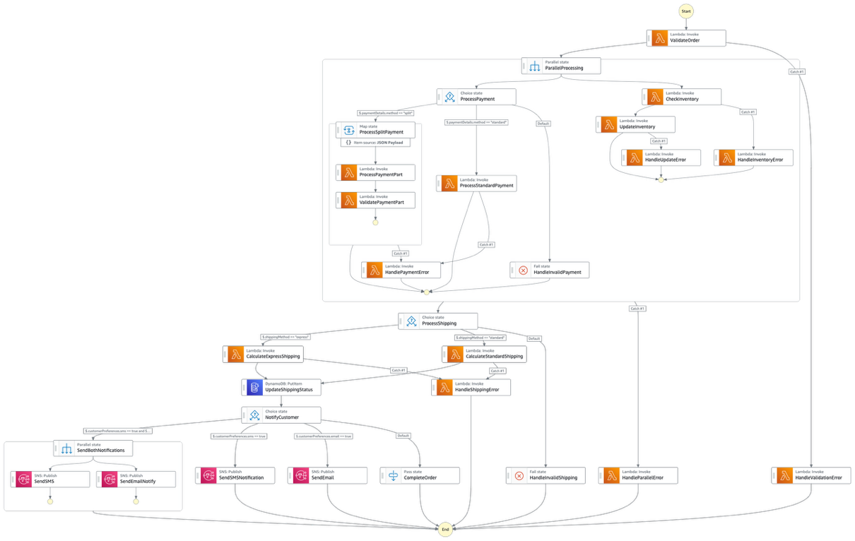
Let’s examine a real-world example of such a monolithic workflow and understand the challenges it presents for development teams, operational efficiency, and business agility. Below is an example of a state machine that is a mix of payment processes, inventory management, and notification mechanisms for an e-commerce implementation:

Figure 1: A state machine that is a mix of payment processes, inventory management, and notification mechanisms for an e-commerce implementation

Figure 1: A state machine that is a mix of payment processes, inventory management, and notification mechanisms for an e-commerce implementation

State Explosion

Modifying a single state in a monolithic workflow triggers a cascade of changes across multiple interconnected states due to their tight coupling and dependencies. For example, adding a new payment method would require modifications across various states including validation, processing, and error handling, creating a ripple effect throughout the workflow. This inter dependency makes even simple changes complex and risky, as altering one component can have unintended consequences on other parts of the workflow.

Looking at the provided architecture, we can see a clear example of state explosion where a single workflow handles multiple business processes including order validation, payment processing, inventory management, shipping calculations, and customer notifications. This creates a complex web of dependent states that becomes increasingly difficult to manage. The result is a “spider web” of states that becomes progressively harder to understand, debug, and maintain.

Version Management

Version management in monolithic workflows requires deploying the entire workflow even for minor changes to individual components, making it difficult to isolate and update specific business logic. The provided architecture demonstrates the version management challenge clearly. For instance, if the shipping calculation logic needs an urgent fix, the entire workflow must be redeployed, requiring comprehensive testing of all components, including unmodified ones, to ensure nothing breaks in the process.

Resource Limitations

While not immediately visible in the architecture diagram, Monolithic workflows face operational constraints as they grow in complexity, particularly with state transitions, maximum event payload size, and execution history size. Refer to the Service quotas documentation to understand such limits. These constraints become critical bottlenecks as workflows grow in complexity and handle increased transaction volumes. In the monolithic state machine, long-running operations like payment processing and shipping calculations, combined with multiple state transitions, could approach these limits, especially for high-volume scenarios.

Additionally, we also come across generic design challenges such as error handling. In monolithic approach, workflows leads to redundant try-catch blocks and retry configurations across different operations. This creates challenges in implementing distinct error strategies for different business scenarios and makes it difficult to maintain proper rollback mechanisms when failures occur in middle states.

These challenges collectively highlight the need for a more modular approach to Step Functions workflow design.

Transforming Complex Workflows Through Decomposition

When transforming complex monolithic workflows into more manageable components, you can employ several decomposition strategies to achieve better modularity and maintainability. These strategies include the parent-child pattern, which creates a hierarchical structure of workflows, domain separation that breaks down workflows based on business capabilities, shared utilities that serve as reusable components for common operations, and specialized error workflows for centralized error handling. Each of these strategies can be implemented either individually or in combination, depending on the specific requirements and complexity of the application, allowing organizations to create more efficient, scalable, and maintainable Step Functions workflows while ensuring proper separation of concerns and reduced operational overhead.

Parent-Child Pattern

The parent-child pattern represents a hierarchical approach to workflow organization where a main (parent) workflow orchestrates multiple sub-workflows (children). Parent workflows manage the overall business process and coordination, while child workflows handles specific, short-lived operations. This pattern is particularly effective when you need to balance between orchestration complexity and execution speed.

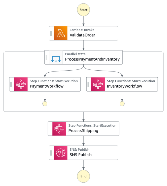
 Figure 2 : Decoupled parent state machine

Figure 2 : Decoupled parent state machine

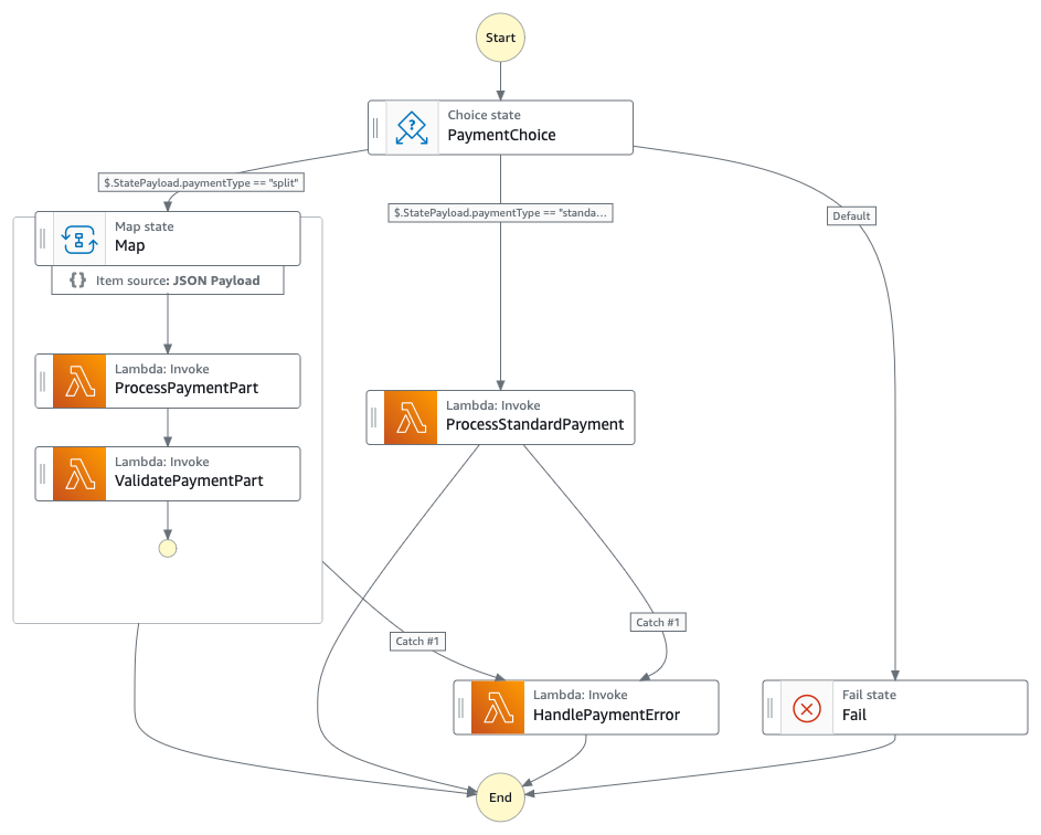
The current monolithic workflow can be restructured by creating a parent workflow focused on order orchestration while delegating specific operations to Express child workflows. The parent workflow would maintain the high-level flow from order validation through completion, while time-sensitive operations like ValidateOrder, ProcessPayment, and ProcessShipping could become Express child workflows.

Kindly note that during an architecture re-vamp, Express workflows are different when compared to Standard Workflows. For example, you cannot have an Express parent workflow invoke a Standard child workflow. Also, an Express workflow does not support Job-run (.sync) or Callback (.waitForTaskToken) service integration patterns. You can refer to the differences between Standard and Express workflows documentation to choose the right architecture pattern.

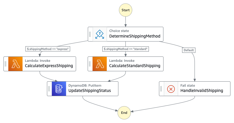
For instance, the payment processing section could be transformed into a child Express workflow that handles all payment-related states (ProcessPayment, ProcessStandardPayment, ValidatePaymentPart) as a single unit. An express workflow is more suitable for sections like payment processing as their executions complete within 5 minutes. Hence this would also reduce the over-all cost of the workflow. Similarly, the shipping calculation logic involving CalculateExpressShipping and CalculateStandardShipping could be consolidated into another Express child workflow, leading to reduced costs and easier updates to shipping logic.

Domain Separation

Domain separation involves breaking down workflows based on distinct business capabilities or functional areas. Each domain-specific workflow becomes responsible for a complete business function, operating independently while communicating through well-defined interfaces. This approach aligns closely with micro-service architecture principles and domain-driven design. The architecture shows clear boundaries between different business domains that can be separated into independent workflows. Three primary domains emerge:

  1. Payment Domain: Encompassing ValidateOrder, ProcessPayment, ValidatePaymentPart, and related error handlers
  2. Inventory Domain: Including CheckInventory, UpdateInventory, and associated states
  3. Shipping Domain: Containing ProcessShipping, shipping calculations, and shipping status updates

Each domain would become its own workflow, with clear input/output contracts. This separation would allow specialized teams to maintain and deploy updates to their domain workflows independently ensuring implementation of domain-specific retry policies, error handling, and business rules without affecting other domains. For example, the payment team could enhance payment processing logic without impacting shipping or inventory operations.

 Figure 3 : Child state machine that handles payment workflow

Figure 3 : Child state machine that handles payment workflow

 Figure 4 : Child state machine that handles shipping workflow

Figure 4 : Child state machine that handles shipping workflow

Shared Utilities

Shared utility workflows serve as reusable components for common operations that appear across multiple business processes. These workflows encapsulate standard functionality like notification handling, data validation, logging, or audit trail creation. By centralizing these common operations, organizations can ensure consistency and reduce duplication across their Step Functions applications.

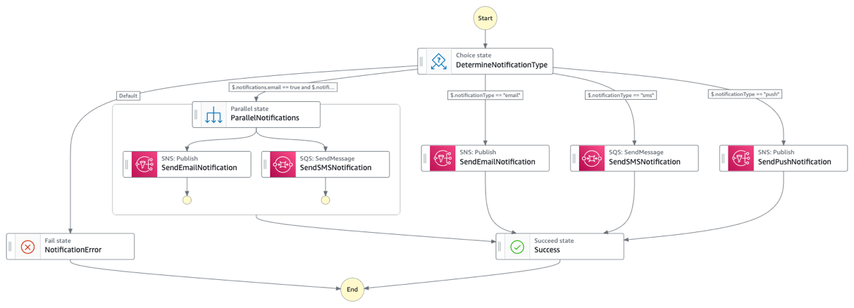
The current architecture repeats several common patterns that could be extracted into shared utility workflows. Most notably, the notification handling logic (SendEmail, SendSMSNotification, SendPushNotification) appears as a cluster of states at the end of the workflow. This could be consolidated into a single “NotificationManager” utility workflow that handles all types of notifications. These utility workflows could then be called from any other workflow in the system, ensuring consistent behavior and reducing code duplication.

 Figure 5 : Re-usable notification workflow

Figure 5 : Re-usable notification workflow

Error Workflows

Error workflows represent a specialized form of decomposition focused on centralizing error handling and recovery logic. Instead of embedding complex error handling in each business workflow, organizations can create dedicated workflows that manage different types of failures, retries, and compensation actions. This approach provides a consistent and maintainable way to handle errors across the application.

Each of these decomposition strategies can be used individually or in combination, depending on the specific needs of your application. For instance, utilization of Domain Separation pattern has resulted in streamlined error workflows. The key is to choose the appropriate combination that provides the right balance of maintainability, scalability, and operational efficiency for your use case. However, implementing all four strategies in a phased approach would provide the most comprehensive solution for long-term maintainability and scalability.

Results:

The comparison between monolithic and decoupled approaches reveals notable differences in performance and operational metrics. In order to emulate similar test environments across monolithic and decomposed state machines, we tested them in us-east-1 AWS region. We made use of the aforementioned workflows, both monolithic and decomposed to achieve a similar end goal. Pricing comparison is based on a monolithic workflow processing 11 state transitions per workflow across 30,000 monthly requests. For the decomposed approach, calculations assume Express child workflows configured with 64MB memory and 100ms execution duration, while the parent workflow handles 8 state transitions per workflow for the same volume of 30,000 monthly requests. AWS Lambda task states in both approaches complete within 2 seconds of execution time.

When decoupled, the workflows can be re-designed to use either Express or Standard mechanisms depending on their execution time and integration pattern requirements. In this use-case, we identified multiple workflows like PaymentProcessing, CalculateExpressShipping that are revamped to use Express workflows as per their requirement. While the monolithic approach shows a slightly faster execution duration of 11.5 seconds compared to 13 seconds in the decomposed approach, the monthly pricing significantly favors the decoupled architecture at $6.37 USD versus $11.90 USD for the monolithic approach. The decoupled approach demonstrates superior debugging capabilities with better error isolation and domain-specific debugging, contrasting with the monolithic approach’s complex debugging challenges due to heavy payloads and middle-state failure tracking. Additionally, the decoupled architecture benefits from smaller payload sizes through distributed data handling, whereas the monolithic workflow carries larger payloads across its 18 state transitions.


Monolithic Approach Decoupled Approach
Execution Duration 11.5 seconds for complete workflow execution 13 seconds with distributed processing across parent-child workflows
Monthly Pricing $11.90 USD (476,000 billable state transitions) $6.37 USD (Combined cost of Standard parent workflow and Express child workflows)
Debug Effort High – Complex debugging due to heavy payloads and difficulty in tracking failures in middle states. Cannot effectively use ResultSelector when final notification state needs all details. Lower – Easier to debug with isolated domains and smaller payloads. Better error isolation and domain-specific debugging.
Payload Size Larger payload size throughout workflow execution as all data needs to be carried across 18 state transitions Smaller payload size due to domain separation and distributed data handling across parent-child workflows

Conclusion

The need for decomposing Step Functions workflows becomes evident when you face challenges with monolithic workflows such as state explosion, version management complexities, and resource limitations. These challenges result in reduced operational efficiency, increased debugging complexity, and higher maintenance overhead as demonstrated by the comparison results showing differences in execution duration, pricing, debugging effort, and payload management. Organizations should evaluate workflow decomposition when they observe workflows exceeding 15-20 states, multiple team involvement in workflow maintenance, frequent independent updates across different business domains, complex error handling requirements, and the need for reusable components across workflows. The implementation of decomposition strategies through parent-child pattern for hierarchical workflow organization, domain separation for business capability isolation, shared utilities for common operations, and dedicated error workflows for centralized error handling has shown tangible benefits in terms of reduced costs, better error isolation, and more efficient payload management.

While implementing decomposition strategies, organizations must be cautious to avoid over-decomposition of workflows, maintaining tight coupling between workflows, and ignoring core design principles of loose coupling and single responsibility. This strategic approach to workflow decomposition ultimately leads to more maintainable, scalable, and cost-effective Step Functions applications that better serve business needs while reducing operational overhead. The transformation from monolithic to decomposed workflows represents a significant architectural improvement that enables organizations to better manage complex business processes while maintaining operational efficiency and system reliability.