Post Syndicated from Brian Zambrano original https://aws.amazon.com/blogs/compute/orchestrating-large-scale-document-processing-with-aws-step-functions-and-amazon-bedrock-batch-inference/
Organizations often have large volumes of documents containing valuable information that remains locked away and unsearchable. This solution addresses the need for a scalable, automated text extraction and knowledge base pipeline that transforms static document collections into intelligent, searchable repositories for generative AI applications.
Organizations can automate the extraction of both content and structured metadata to build comprehensive knowledge bases that power retrieval-augmented generation (RAG) solutions while significantly reducing manual processing costs and time-to-value. The architecture not only demonstrates the processing of 500 research papers automatically, but also scales to handle enterprise document volumes cost-effectively through the Amazon Bedrock batch inference pricing model.
Overview
Amazon Bedrock batch inference is a feature of Amazon Bedrock that offers a 50% discount on inference requests. Although Amazon Bedrock schedules and runs the batch job (needing a minimum of 100 inference requests) as capacity becomes available, the inference won’t be real-time. For use cases where you can accommodate minutes to hours of latency, Amazon Bedrock batch inference is a good option.
This post demonstrates how to build an automated, serverless pipeline using AWS Step Functions, Amazon Textract, Amazon Bedrock batch inference, and Amazon Bedrock Knowledge Bases to extract text, create metadata, and load it into a knowledge base at scale. The example solution processes 500 research papers in PDF format from Amazon Science, extracts text using Amazon Textract, generated structured metadata with Amazon Bedrock batch inference and the Amazon Nova Pro model, and loads the final output, including Amazon Bedrock Knowledge Base filter, into an Amazon Bedrock Knowledge Base.
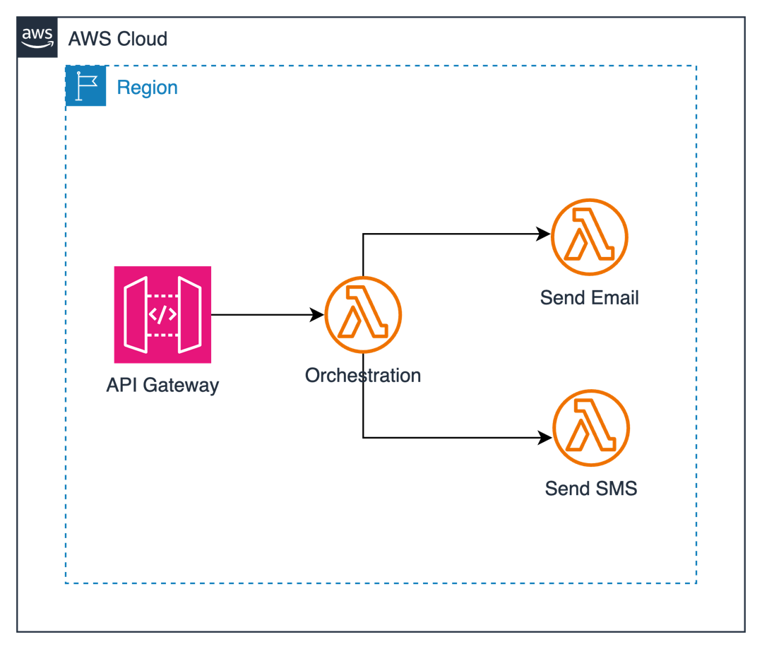
Architecture
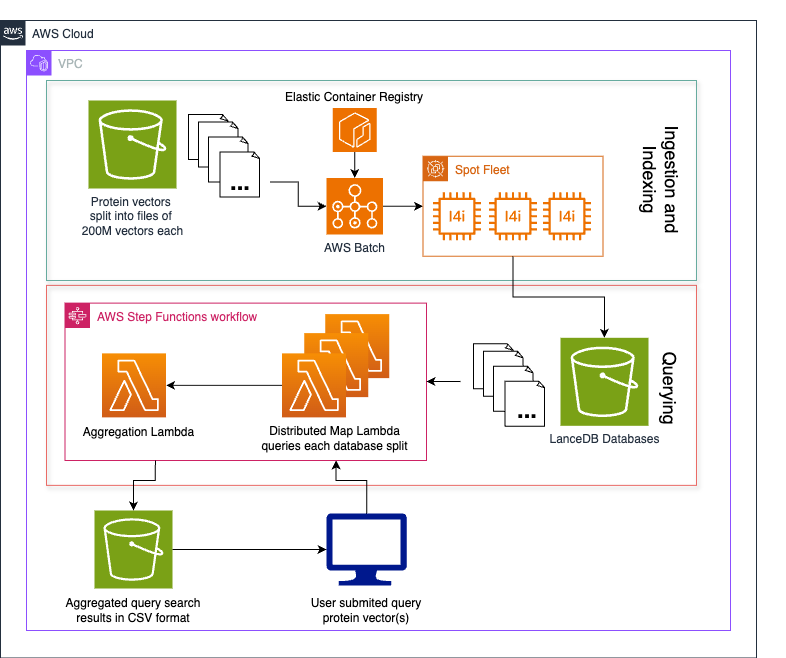
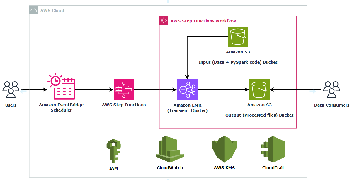
This solution uses Step Functions with parallel Amazon Textract job processing through child workflows run by Distributed Map. You can use the concurrency controls offered by Distributed Map to process documents as quickly as possible within your Amazon Textract quotas. Increasing processing speed necessitates adjusting your Amazon Textract quota and updating the Distributed Map configuration. Amazon Bedrock batch inference handles concurrency, scaling, and throttling. This means that you can create the job without managing these complexities.
In this example implementation, the solution processes research papers to extract metadata such as:
- Code availability and repository locations
- Dataset availability and access methods
- Research methodology types
- Reproducibility indicators
- Other relevant research attributes
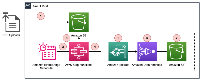
The high-level parts of this solution include:
- Extracting text from PDF documents with Amazon Textract in parallel, through Step Functions Distributed Map.
- Analyzing extracted text using Amazon Bedrock batch inference to extract structured metadata.
- Loading extract text and metadata into a searchable knowledge base using Amazon Bedrock Knowledge Bases with Amazon OpenSearch Serverless.
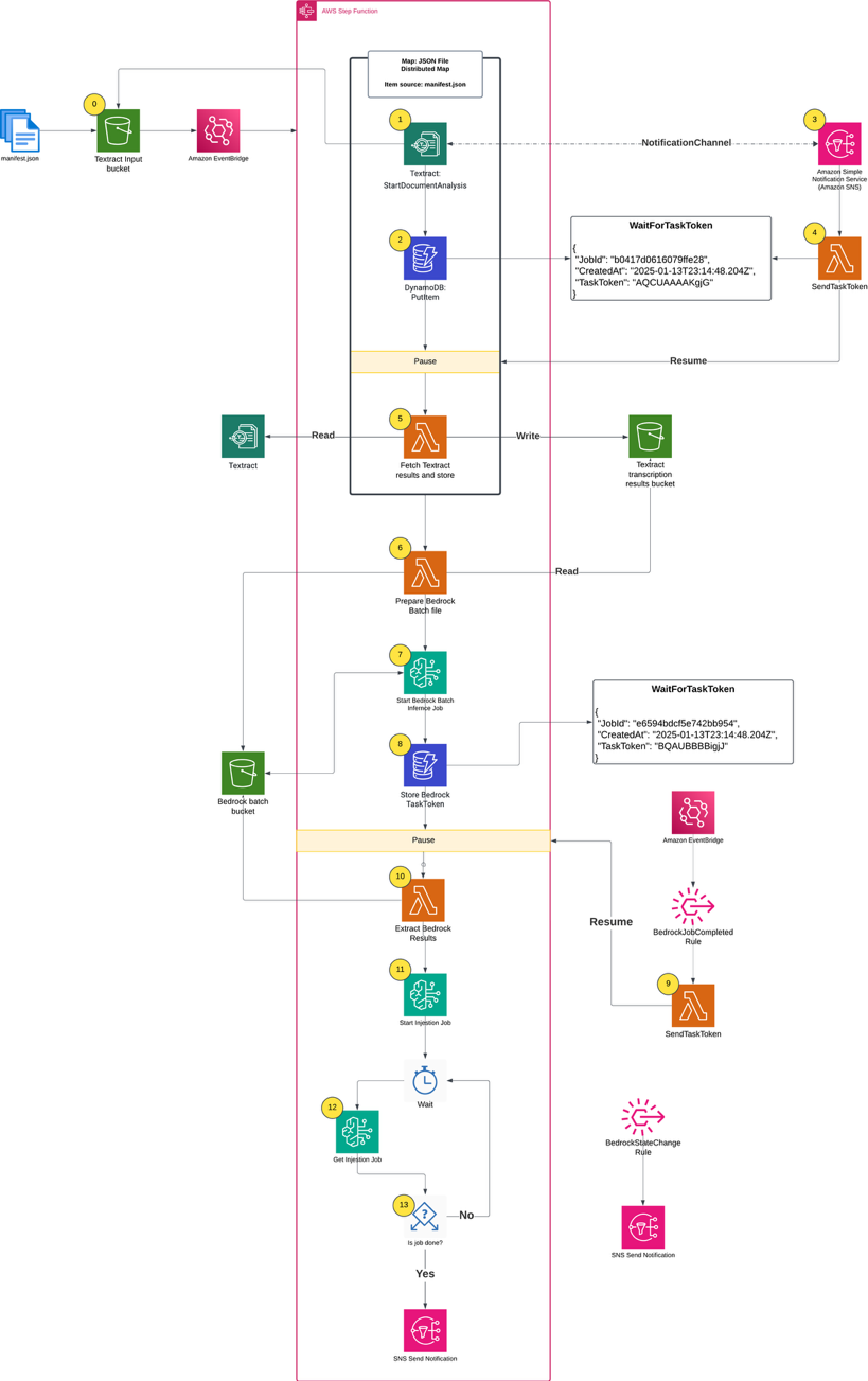
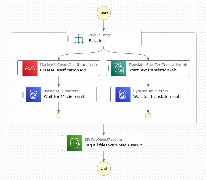
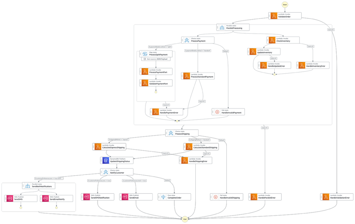
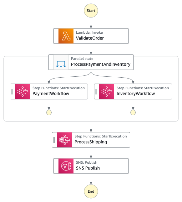
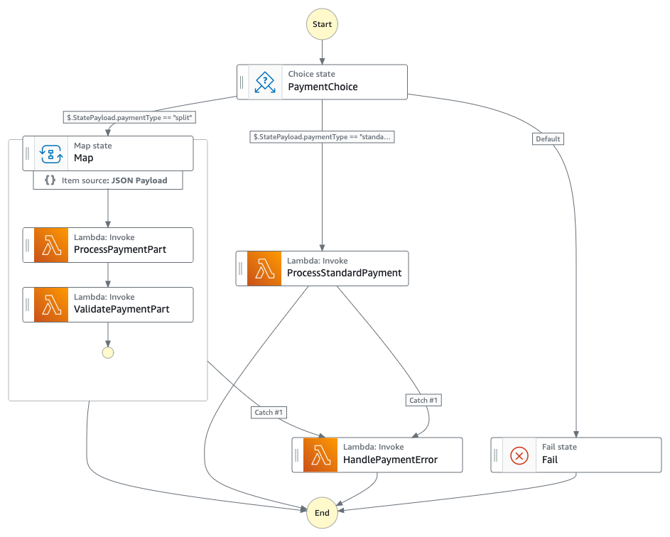
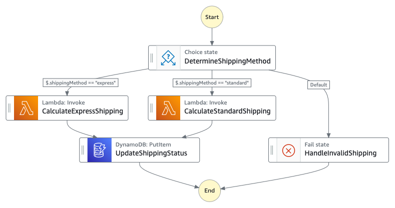
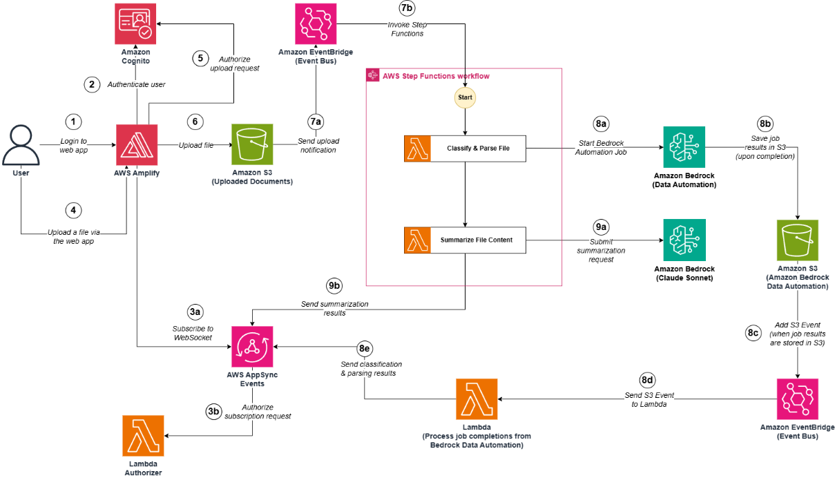
Figure 1. Complete architecture diagram
Prerequisites
The following prerequisites are necessary to complete this solution:
- Access to an AWS account through the AWS Management Console and the AWS Command Line Interface (AWS CLI). The AWS Identity and Access Management (IAM) user that you use must have permissions to make the necessary AWS service calls and manage AWS resources mentioned in this post. While providing permissions to the IAM user, follow the principle of least-privilege.
- AWS CLI installed and configured. If you are using long-term credentials such as access keys, then follow manage access keys for IAM users and secure access keys for best practices.
- Git Installed.
- Python 3.13+ installed.
- Node and npm installed.
- AWS Cloud Development Kit (AWS CDK) installed.
Running the solution
The complete solution uses AWS CDK to implement two AWS CloudFormation stacks:
- BedrockKnowledgeBaseStack: Creates the knowledge base infrastructure
- SFNBatchInferenceStack: Implements the main processing workflow
First, clone the GitHub repository into your local development environment and install the requirements:
git clone https://github.com/aws-samples/sample-step-functions-batch-inference.git .
cd sample-step-functions-batch-inference
npm install
Next, deploy the solution using AWS CDK:
cdk deploy --all
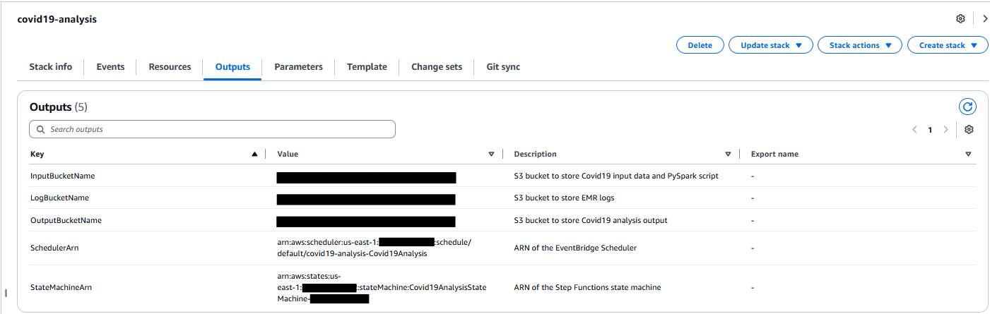
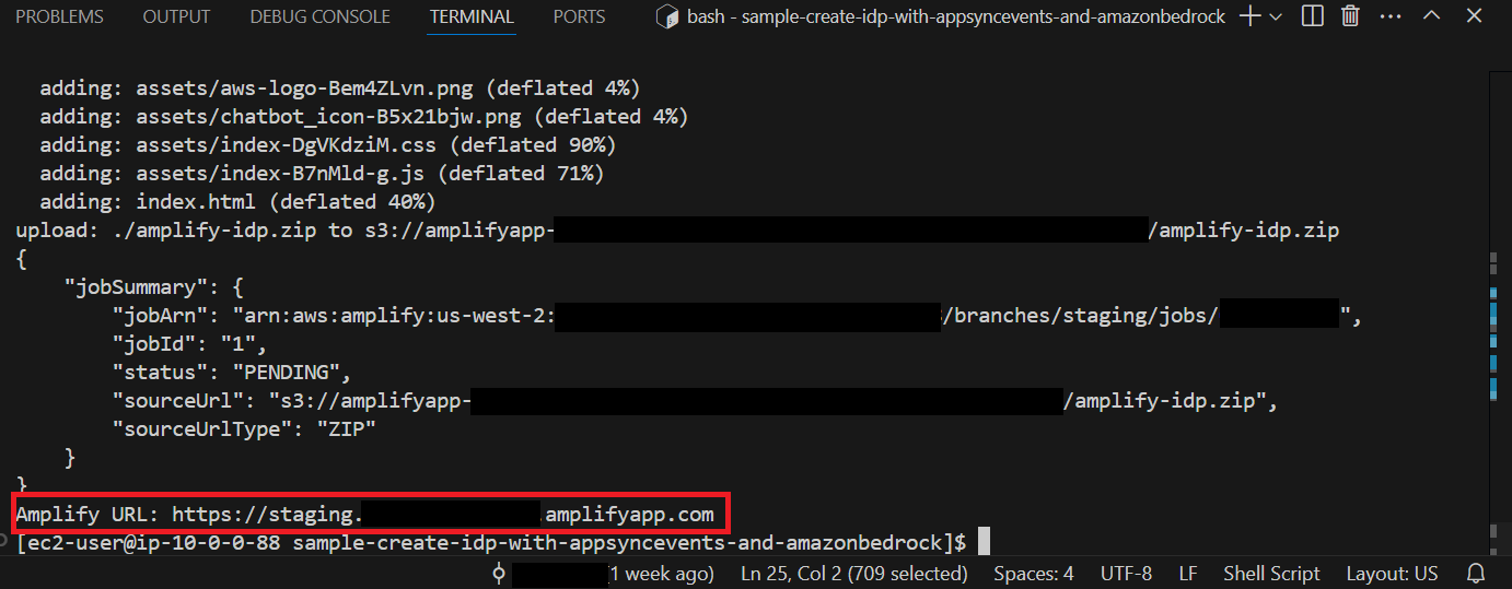
After deploying the cdk stacks, upload your data sources (PDF files) into the AWS CDK-created Amazon S3 input bucket. In this example, I uploaded 500 Amazon Science papers. The input bucket name is included in the AWS CDK outputs:
Outputs:
SFNBatchInference.BatchInputBucketName = sfnbatchinference-batchinputbucket11aaa222-nrjki8tewwww
Parallel text extraction
The process begins when you upload a manifest.json file to the input bucket. The manifest file lists the files for processing, which already exist in the input bucket. The filenames listed in manifest.json define what constitutes a single processing job run. To create another run, you would create a different manifest.json and upload it to the same S3 bucket.
The AWS CDK definition for the input bucket includes Amazon EventBridge notifications and creates a rule that triggers the Step Functions workflow whenever a manifest.json file is uploaded.
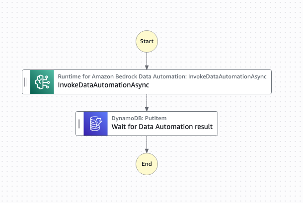
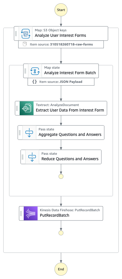
The first step in the Step Functions workflow is a Distributed Map run that performs the following actions for each PDF in the manifest file:
- Starts an Amazon Textract job, providing an Amazon Simple Notification Service (Amazon SNS) topic for completion notification.
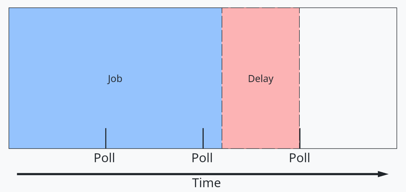
- Writes the Step Functions task token to Amazon DynamoDB, pausing the individual child workflow.
- Processes the Amazon SNS message when the Amazon Textract job completes, triggering an AWS Lambda function.
- Uses a Lambda function to retrieve the task token from DynamoDB using the Amazon Textract JobId.
- Fetches the raw results from Amazon Textract, organizes the text for readability, and writes results to an S3 bucket

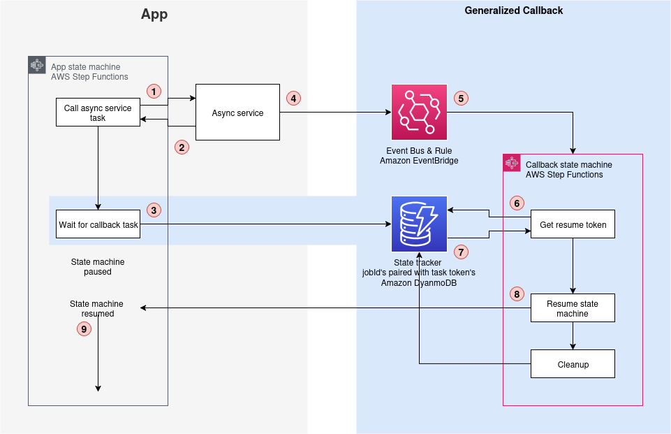
A key component of this architecture is the callback pattern that Amazon Textract supports using the NotificationChannel option, as shown in the preceding figure. The AWS CDK definition the Step Functions state that starts the Amazon Textract job is shown in the following.
The Lambda function that handles task tokens extracts the Amazon Textract JobId from the Amazon SNS message, fetches the TaskToken from DynamoDB, and resumes the Step Functions Workflow by sending the TaskToken:
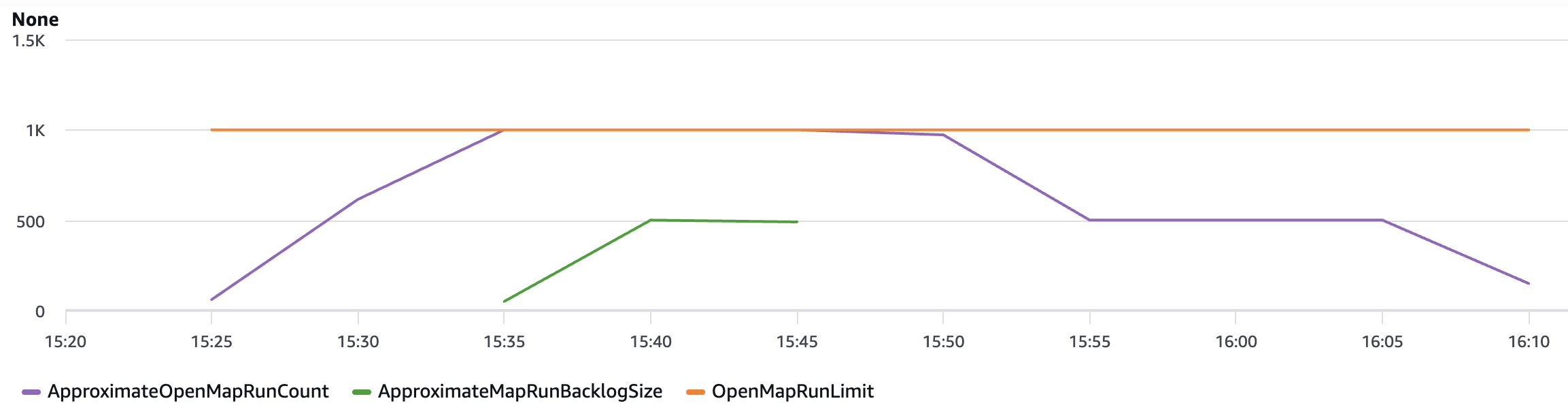
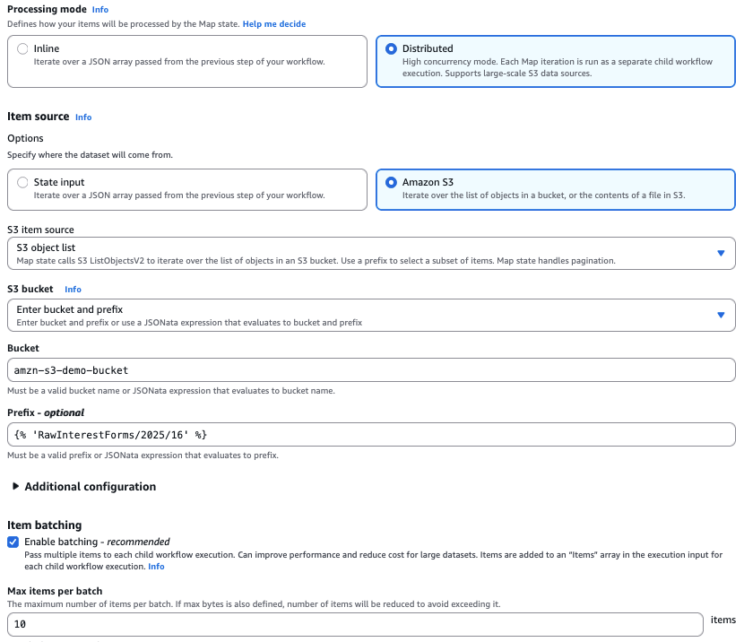
The Distributed Map runs up to 10 child workflows concurrently, controlled by the maxConcurrency setting. Although Step Functions supports running up to 10,000 child workflow executions, the practical concurrency for this solution is constrained by Amazon Textract quotas. The startDocumentAnalysis API has a default quota of 10 requests per second (RPS), which means you must consider this limit when scaling your document processing workloads and potentially request quota increases for higher throughput requirements.
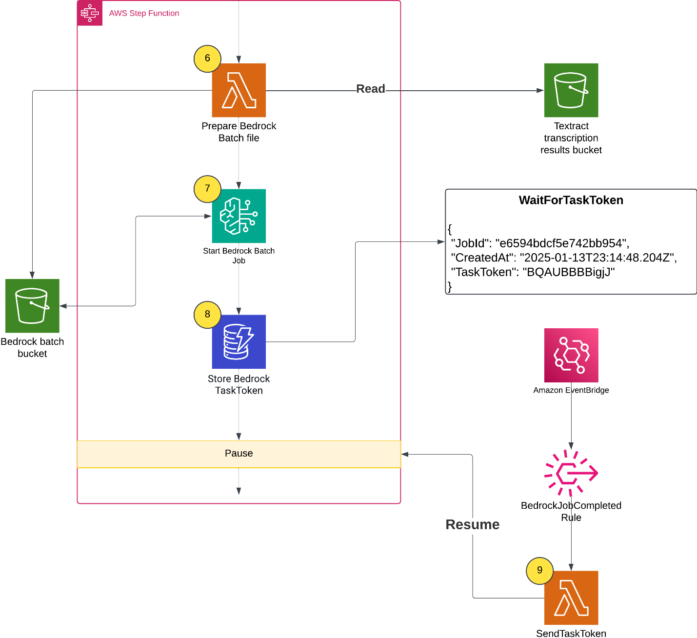
Running Amazon Bedrock batch inference
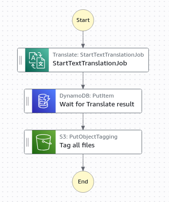
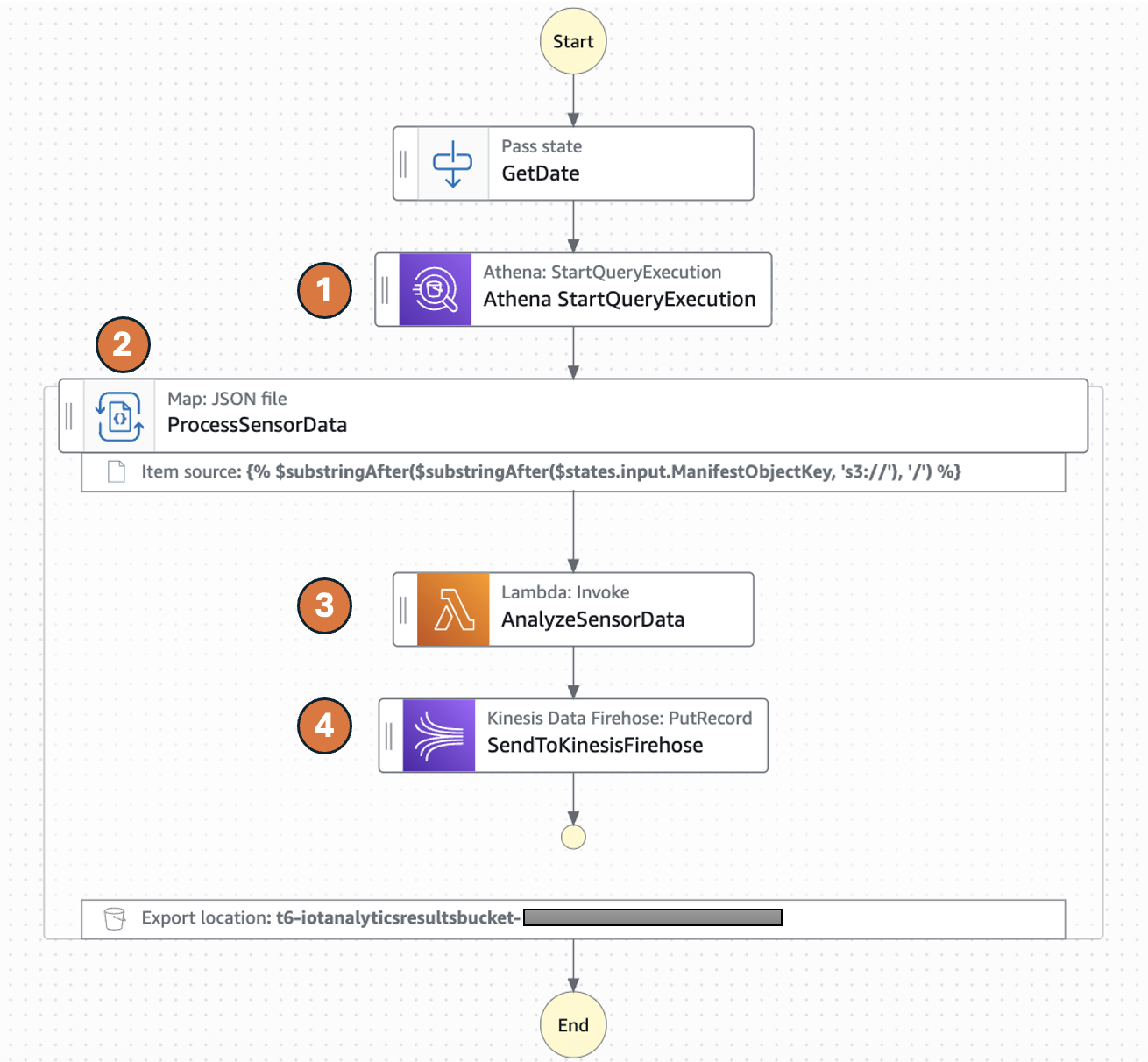
When all of the Amazon Textract jobs finish, the Distributed Map state creates an Amazon Bedrock batch inference input file, launches the Amazon Bedrock inference job, and waits for it to complete.
- A Lambda function collects text results from Amazon S3 and creates an Amazon Bedrock batch inference input file with custom prompts.
- The workflow starts the Amazon Bedrock batch inference job by calling createModelInvocationJob and sending the batch inference input file as input.
- The workflow pauses and stores the task token in DynamoDB.
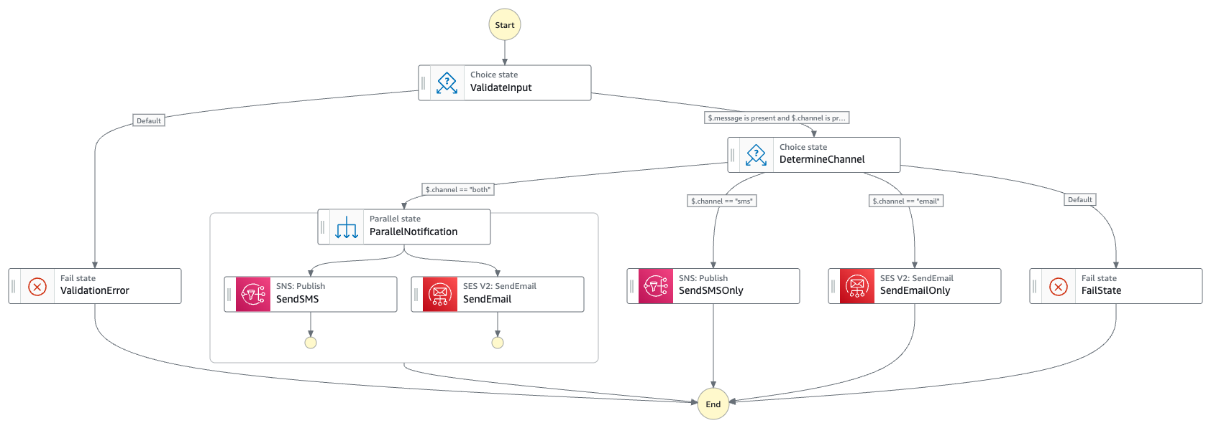
- An EventBridge rule matches completed Amazon Bedrock batch inference events, and upon job completion and triggers a Lambda function. The Lambda function retrieves the task token and resumes the workflow, as shown in the following figure.
A batch inference input is a single jsonl file with multiple entries such as the following example. The prompt in each inference request instructs the large language model (LLM) to analyze the paper and extract metadata. Read the full prompt template in the GitHub repository.
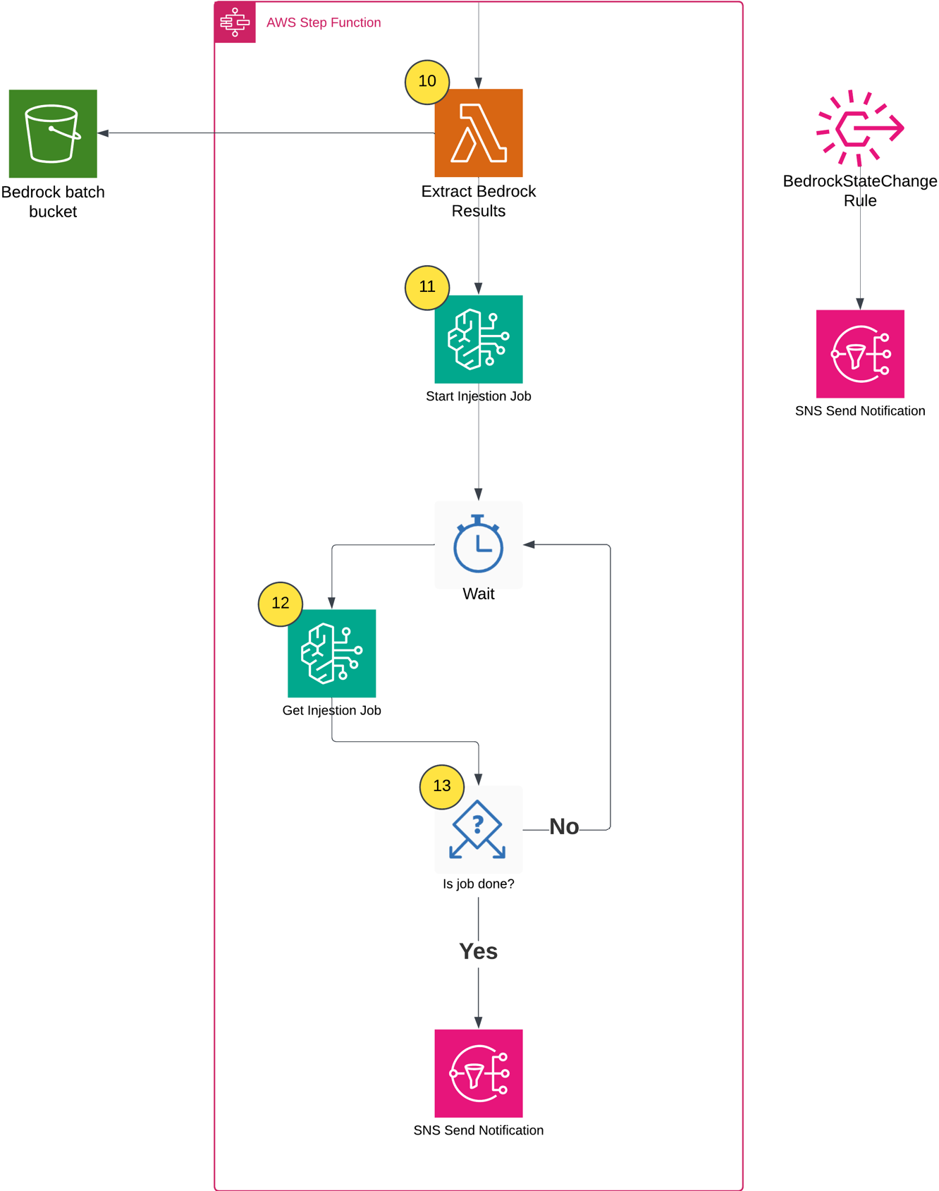
Populating the Amazon Bedrock Knowledge Base
After the batch inference completes, the workflow does the following:
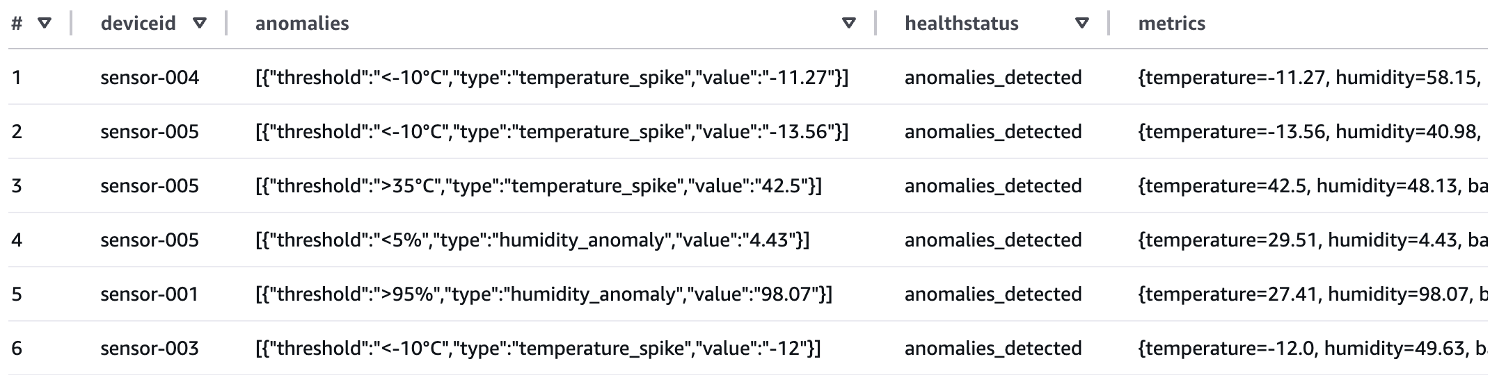
- Extracts inference results and creates metadata files based on the Amazon Bedrock inference results (example metadata shown in the following figure).
- Starts an Amazon Bedrock Knowledge Base ingestion job.
- Monitors the ingestion job status using Step Functions Wait and Choice states.
- Sends a completion notification through Amazon SNS.
The following shows the example metadata format:
Testing the knowledge base
After the workflow completes successfully, you can test the knowledge base to verify that the documents and metadata have been properly ingested and are searchable. There are two practical methods for testing an Amazon Bedrock Knowledge Base:
- Using the Console
- Using the AWS SDK to run a query
Testing through the Console
The Console provides an intuitive interface for testing your knowledge base queries with metadata filters:
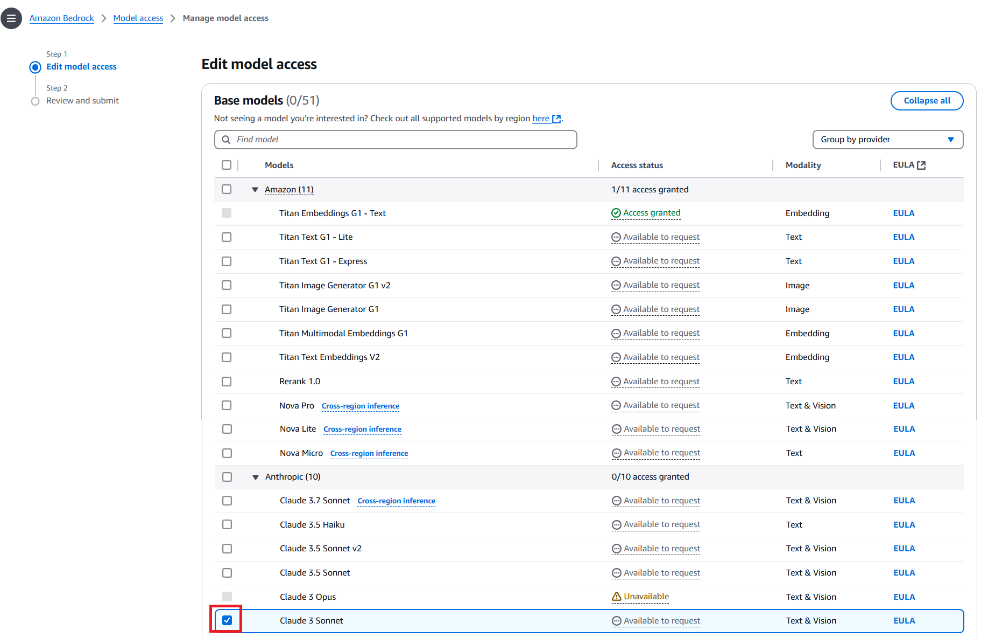
- Navigate to the Amazon Bedrock console.
- In the left navigation pane, choose Knowledge Bases under the Build section.
- Choose the knowledge base created by the AWS CDK deployment (the name will be output by the AWS CDK stack).
- Choose the Test button in the upper right corner.
- In the test interface, choose your preferred foundation model (FM) (such as Amazon Nova Pro).
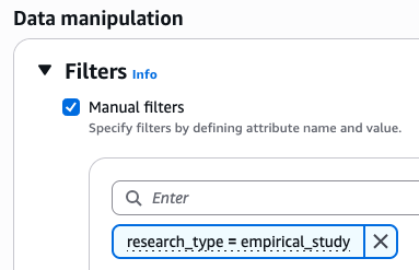
- Expand the Configurations column, then navigate to the Filters section.
- Configure filters based on the extracted metadata, as shown in the following figure.
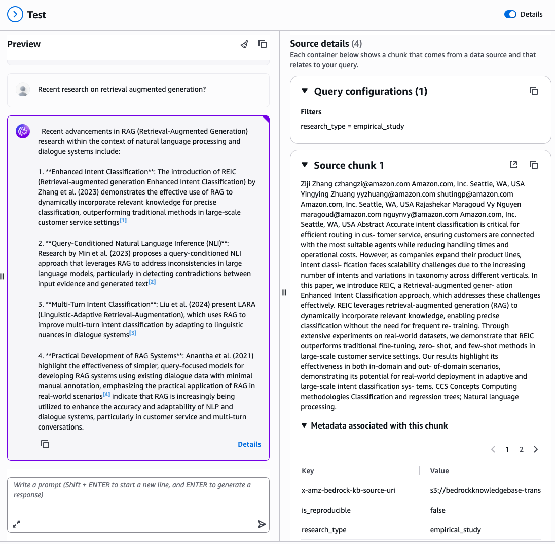
Enter a natural language query related to your documents, for example: “Recent research on retrieval augmented generation?”
The console displays the generated response along with source attributions showing which documents were retrieved and used to formulate the answer, filtered by your specified metadata attributes, as shown in the following figure.
Testing via API
For programmatic testing and integration into applications, use the AWS SDK with metadata filtering. The following is a Python example using boto3:
The following is the test script output:
Conclusion
This solution demonstrates how to combine multiple AWS AI and serverless services to build a scalable document processing pipeline. Organizations can use AWS Step Functions for orchestration, Amazon Textract for document processing, Amazon Bedrock batch inference for intelligent content analysis, and Amazon Bedrock Knowledge Bases for searchable storage. In turn, they can automate the extraction of insights from large document collections while optimizing costs.
Following this solution, you can build a solid foundation for production-scale document processing pipelines that maintain the flexibility to adapt to your specific requirements while making sure of reliability, scalability, and operational excellence. Follow this link to learn more about serverless architectures.
 Maria John is a Senior Solutions Architect at Amazon Web Services, helping customers build solutions on AWS.
 Philip Whiteside is a Senior Solutions Architect at Amazon Web Services. Philip is passionate about overcoming barriers by utilizing technology.
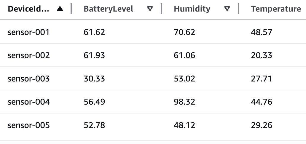


