All posts by Sindhura Palakodety

Scale distributed AI workloads with Ray and Anyscale on Amazon EC2

Post Syndicated from Sindhura Palakodety original https://aws.amazon.com/blogs/architecture/scale-distributed-ai-workloads-with-ray-and-anyscale-on-amazon-ec2/

If you are building multimodal artificial intelligence and machine learning (AI/ML) pipelines on Amazon Elastic Compute Cloud (Amazon EC2) that process text, video, and audio, you have likely hit at least one of these challenges. Scaling from a single instance to distributed compute without rewriting code, managing costs across training, fine-tuning, and inference, and keeping up with an evolving network of models, frameworks, and hardware are among the biggest challenges AI engineers face today. These challenges compound when each pipeline stage has distinct compute, networking, and storage requirements, and multiple teams own separate parts of the workflow.

This post shows how the Ray-powered Anyscale application on AWS helps you tackle these challenges. You will learn how to: deploy Ray across three AWS compute options based on your operational requirements, optimize costs by matching heterogeneous instance types to each pipeline stage, and scale from prototype to production without code changes.

How Anyscale builds on Ray

Ray Core is the distributed computing foundation underlying the entire framework. It provides primitives for parallelizing Python workloads across clusters, handling task scheduling, fault tolerance, and autoscaling. Ray AI libraries are built on top of Ray Core. As a result, custom workloads that don’t fit a standard pattern can still use the same distributed infrastructure.

Ray Data ingests and transforms datasets at scale, feeding processed data into training, tuning, and inference stages. Ray Train orchestrates distributed multi-node jobs with built-in fault tolerance, supporting foundation model fine-tuning across architectures such as Llama and Mistral with automatic selection of data-parallel, model-parallel, or pipeline-parallel strategies. Ray Tune parallelizes hyperparameter experiments across large clusters. Ray Serve runs production inference endpoints with dynamic batching, automatic scaling, and multi-model deployment support. Ray RLlib supports distributed reinforcement learning workloads, including reinforcement learning from human feedback (RLHF) for large language model (LLM) alignment.

Anyscale on AWS

Many AWS customers already run self-managed Ray clusters on Amazon EC2. Anyscale builds on that foundation as a fully managed service that deploys within your AWS account, integrating with your existing Amazon Virtual Private Cloud (Amazon VPC) networks, AWS Identity and Access Management (IAM) roles, and compliance frameworks. The application handles cluster management, autoscaling, and cost controls so you can focus on workloads rather than infrastructure.

AWS and Anyscale together address three dimensions of production AI/ML: cost-efficient infrastructure spanning the full Amazon EC2 portfolio, a Ray-on-Anyscale stack that scales reliably from experimentation to production, and an integrated framework that reduces friction at every stage of development. With Anyscale, you can map each pipeline stage to the appropriate instance type. Intel and AMD-based instances handle preprocessing, tokenization, and feature extraction. AWS Graviton-based instances cover preprocessing, worker nodes, embedding generation, and lightweight inference where price-performance matters. NVIDIA GPU instances and AWS Trainium handle training and fine-tuning. AWS Inferentia serves high-throughput inference endpoints. Amazon EC2 Spot Instances run automatically for batch training, preprocessing, and hyperparameter sweeps.

Anyscale deployment architecture on AWS

Three deployment options provide flexibility based on operational requirements:

Amazon EC2 with Elastic Fabric Adapter (EFA) provides direct compute control and high-performance inter-node networking.

Amazon Elastic Kubernetes Service (Amazon EKS) with EFA supports containerized workloads.

Amazon SageMaker HyperPod delivers managed large-scale foundation model training with built-in cluster resiliency.

Regardless of the deployment path, Ray libraries handle distinct pipeline stages. Ray Data orchestrates preprocessing across CPU-only instances, AWS Graviton-based instances, GPU instances, and Spot Instances. Ray Train, Ray Serve, and Ray RLlib handle distributed training, inference serving, and reinforcement learning on NVIDIA GPU instances and AWS AI chips.
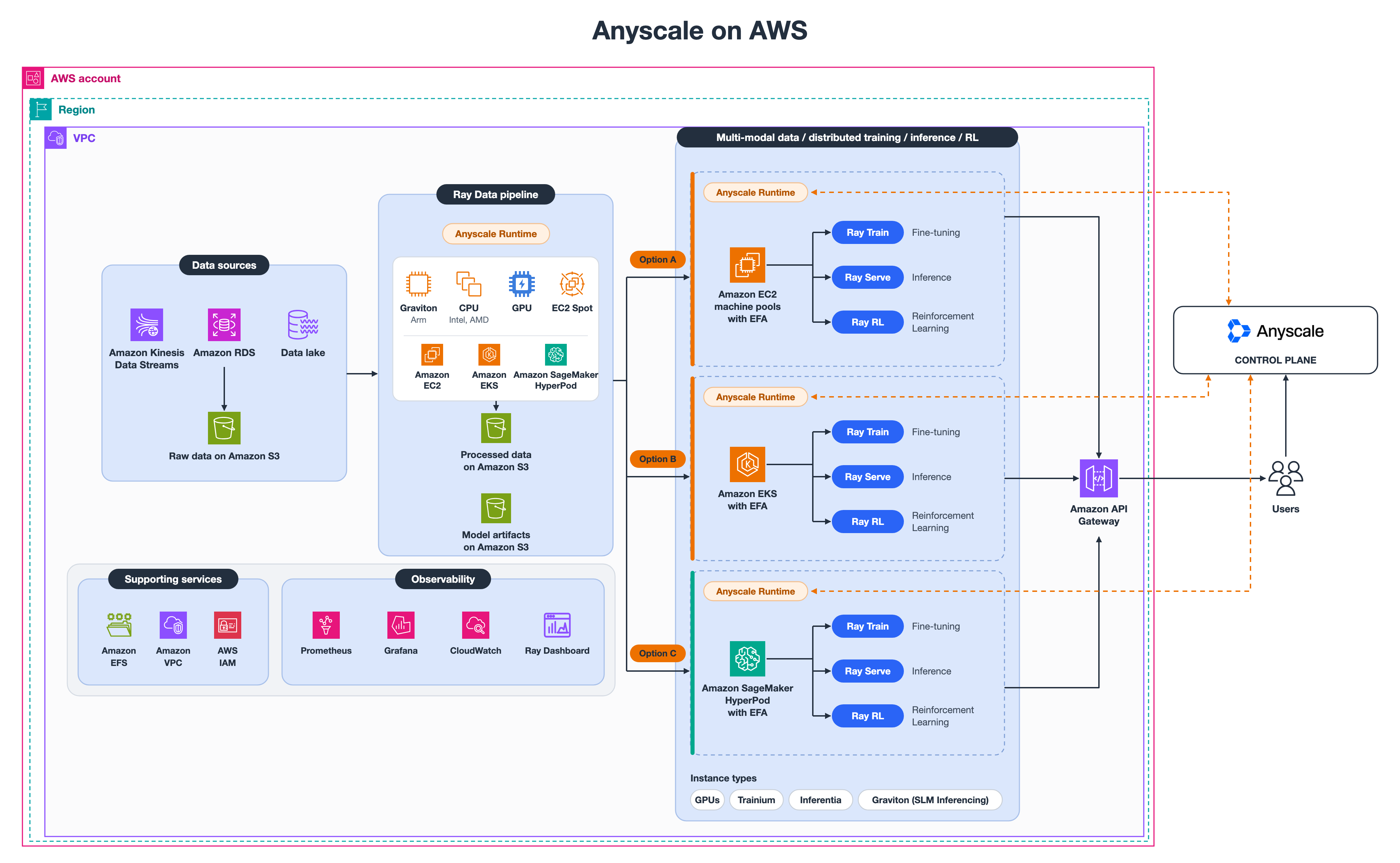
Reference architecture showing the Anyscale on AWS solution deployed across multiple AWS services

Figure 1: Anyscale on AWS architecture

Anyscale runs a hosted control plane that sends instructions to an operator deployed in your AWS environment. The data plane (Amazon EC2 instances, storage, and networking) stays in your account, and Anyscale manages Ray cluster lifecycle without direct access to your data.

Option A: Amazon EC2

Amazon EC2 supports the full pipeline without constraint. This makes it the recommended default for teams running EC2-based workloads who want to scale into AI/ML without retooling their operations. Ray Data runs preprocessing on cost-efficient instance types including Spot Instances and Graviton processors. Ray Train handles distributed training on GPU and Trainium instances with EFA. Ray Tune runs hyperparameter search across CPU and GPU instances. Ray Serve deploys inference on Inferentia or Graviton. Ray supports reinforcement learning through RLlib on GPU instances, and RLHF workflows run through frameworks such as OpenRLHF.

Anyscale manages instance lifecycle, provisioning and terminating nodes based on demand. Amazon Simple Storage Service (Amazon S3) handles datasets, checkpoints, and model artifacts. Amazon FSx for Lustre provides parallel file system throughput for training jobs with repeated large-dataset reads. EFA is available on supported instance types for multi-node training.

Option B: Amazon EKS

Amazon EKS runs the same full pipeline within a Kubernetes environment. This makes it the right choice if your organization already manages Kubernetes and wants Ray to share the same infrastructure and tooling. The Anyscale operator deploys Ray nodes as pods, and Ray libraries run identically to the Amazon EC2 path at the application layer.

Karpenter handles node autoscaling, provisioning GPU nodes for training, Graviton nodes for preprocessing and inference, and Spot Instances for batch workloads. Ray Serve benefits from Kubernetes-integrated zero-downtime upgrades for production inference deployments. The tradeoff: Amazon EKS adds container orchestration complexity and requires custom configuration for the Anyscale operator.

Option C: Amazon SageMaker HyperPod

Amazon SageMaker HyperPod is purpose-built for resilience-critical stages where multi-week runs on large GPU or Trainium clusters make node failures expensive. It continuously monitors cluster health, automatically replaces unhealthy nodes, and resumes from the last checkpoint without manual intervention. HyperPod supports both Slurm-orchestrated and Amazon EKS-based clusters, and now supports the full model development lifecycle including inference deployment. Amazon SageMaker Studio integration adds experiment tracking and model management.

Native integrations shared by EC2, EKS, and HyperPod

Networking and storage

EFA provides low-latency, high-bandwidth inter-node communication for distributed training on all three deployment paths. Amazon S3 is the primary store for datasets, checkpoints, and artifacts. Ray Data pipelines read directly from Amazon S3-based data lakes. Amazon FSx for Lustre integrates with S3 for parallel file system throughput. Amazon Elastic File System (Amazon EFS) covers shared file access for workspaces and notebooks.

Security and compliance

Amazon Virtual Private Cloud (Amazon VPC) network isolation, IAM role-based access control, and AWS Key Management Service (AWS KMS) encryption at rest and in transit apply regardless of deployment path. Data stays within your AWS account and encryption keys remain under your control. This architecture supports compliance with frameworks including HIPAA and SOC 2 without changes to Ray workload code.

Observability

Anyscale monitoring provides workload-specific dashboards covering training progress, pipeline throughput, and request latency. Grafana dashboards are accessible from the Anyscale console. Amazon CloudWatch handles AWS metrics, logs, and alarms. Prometheus supports custom metrics collection for teams with existing monitoring pipelines.

Each deployment path follows the same workflow: Ray Data feeds processed data to Anyscale Runtime, Ray Train orchestrates training, Ray Serve handles inference through Amazon API Gateway, and Ray RLlib supports reinforcement learning.

Cost optimization and provisioning

Right-sizing compute per stage

AWS Graviton-based instances deliver strong price-performance for CPU-bound Ray workloads across preprocessing, embedding generation, and lightweight inference. PyTorch inference on Graviton3 C7g instances shows up to 50% cost savings versus x86 equivalents (Tomaz Berisa, n.d.). Graviton4 adds 30% better compute per core and 75% more memory bandwidth than Graviton3 (AWS, n.d.). Graviton also runs small language models (1–7B parameters) cost-efficiently for generative AI inference.

Intel-based instances provide strong x86 price-performance for tokenization, batch transforms, and workloads requiring broad framework compatibility. AMD-based instances deliver strong performance for CPU-intensive preprocessing, feature engineering, and inference workloads requiring maximum throughput per core. NVIDIA GPU instances provide high throughput for distributed training, fine-tuning, and large-model inference.

AWS Trainium2 delivers 30–40% better price-performance than comparable GPU instances for training at scale (AWS, n.d.). AWS Inferentia2 provides up to 4x higher throughput and 10x lower latency than its predecessor for production inference. Ray auto-detects accelerator types, so Anyscale routes each workload stage to the appropriate hardware without manual configuration.

Spot Instances with Ray fault tolerance

Anyscale keeps head nodes on On-Demand and runs workers on Spot with automatic fallback. Ray Data retries failed tasks on replacement nodes. Ray Train resumes from checkpoints, achieving up to 60% savings on distributed training. Ray Serve proactively migrates replicas on the 2-minute preemption warning.

Capacity Blocks and On-Demand Capacity Reservations

For scheduled training runs requiring capacity availability, Amazon EC2 Capacity Blocks reserve 1–64 accelerated instances for up to six months, bookable eight weeks in advance. Each block supports up to 512 GPUs or 1,024 Trainium chips, placed in Amazon EC2 UltraClusters with petabit-scale networking. Anyscale machine pools reference capacity reservations directly with priority-ordered fallback: Capacity Block, then Spot, then On-Demand. On-Demand Capacity Reservations (ODCRs) provide open-ended capacity availability.

Combined provisioning strategy

Anyscale runs two-layer autoscaling: Ray Serve scales replicas on request metrics while the cluster autoscaler provisions and terminates nodes. The recommended purchasing stack starts with AWS Compute Savings Plans, saving up to 66% across Graviton, GPU, Trainium, and Inferentia. Layer on Spot for fault-tolerant batch jobs, Capacity Blocks for scheduled training, and On-Demand for burst.

Getting started: From prototype to production

Your path follows four phases, each building on the last without code changes:

Phase 1: Validate locally (1–2 days). Start with Ray on a single Amazon EC2 instance or your laptop. Build your data pipeline and training loop, and validate model quality before touching distributed infrastructure.

Phase 2: Scale data (1–2 weeks). Deploy Ray Data with AWS Graviton and Amazon EC2 Spot Instances to process your full dataset at scale, with Spot Instances reducing preprocessing costs by up to 90% (AWS, n.d.).

Phase 3: Scale training (2–4 weeks). Choose your deployment option: Amazon EC2 for maximum flexibility, Amazon EKS for Kubernetes-native environments, or Amazon SageMaker HyperPod for resilience-critical runs. Scale training across multiple GPUs or AWS Trainium instances with EFA.

Phase 4: Deploy inference (1–2 weeks). Deploy Ray Serve for model serving with autoscaling configured to your traffic patterns.

The same code runs across all four phases. Moving from a single instance to a multi-node cluster requires only configuration changes managed by Anyscale.

Conclusion

Ray and Anyscale on AWS provide a practical path from prototype to production across the full AI/ML pipeline. Three deployment options address different operational requirements: Amazon EC2 for maximum flexibility, Amazon EKS for Kubernetes-native environments, and Amazon SageMaker HyperPod for resilience-critical training. With heterogeneous clusters mixing Amazon EC2 Spot Instances, AWS Graviton, NVIDIA GPUs, AWS Trainium, and AWS Inferentia, you can match compute to each pipeline stage. The same Ray code runs from a single instance to a multi-node cluster without modification, and Anyscale handles cluster management, fault tolerance, autoscaling, and resource orchestration.

Your next steps depend on where you are today:

  • Already running Ray on AWS – deploy Anyscale through the AWS Marketplace for managed autoscaling, cost controls, and governance.
  • New to distributed ML – start with the Anyscale documentation on a single Amazon EC2 instance, then scale out.
  • Evaluating Anyscale – explore the Ray quickstart for architecture guides and tutorials.

For more on the AWS services covered in this post, see the documentation for Amazon EC2, Amazon EKS, Amazon SageMaker HyperPod, AWS Trainium, AWS Inferentia, and AWS Graviton.



About the authors

Sindhura Palakodety

Sindhura Palakodety

Sindhura is a Senior Solutions Architect at Amazon Web Services (AWS) and Single-Threaded Leader (STL) for ISV Generative AI, where she is dedicated to empowering customers in developing enterprise-scale, Well-Architected solutions. She specializes in generative AI and data analytics domains, enabling organizations to leverage innovative technologies for transformative business outcomes.

Kinnar Sen

Kinnar Sen

Kinnar Sen is a Principal Specialist Solutions Architect at AWS for the Amazon EC2 portfolio. He has more than 20 years of industry experience in research, consultancy, engineering, and architecture, including 15 years in cloud computing. He works with AWS customers worldwide to design, migrate, and scale production workloads on EC2. Kinnar leads EC2 technical strategy for generative AI, agentic, and data analytics workloads, with a focus on price performance. He sets long-term technical direction across specialist and field teams, works with EC2 product and engineering leaders to shape what AWS builds next, and mentors the next generation of builders.

Arnab Sinha

Arnab Sinha

Arnab is a Senior Solutions Architect at Amazon Web Services (AWS), where he helps independent software vendors (ISVs) and startups build world-class solutions on AWS. He has deep expertise in cloud infrastructure, machine learning (ML), and artificial intelligence (AI), and he advises organizations on how to architect, optimize, and scale their workloads on AWS to drive business outcomes.

Build an analytics pipeline for a multi-account support case dashboard

Post Syndicated from Sindhura Palakodety original https://aws.amazon.com/blogs/big-data/build-an-analytics-pipeline-for-a-multi-account-support-case-dashboard/

As organizations mature in their cloud journey, they have many accounts (even hundreds) that they need to manage. Imagine having to manage support cases for these accounts without a unified dashboard. Administrators have to access each account either by switching roles or with single sign-on (SSO) in order to view and manage support cases.

This post demonstrates how you can build an analytics pipeline to push support cases created in individual member AWS accounts into a central account. We also show you how to build an analytics dashboard to gain visibility and insights on all support cases created in various accounts within your organization.

Overview of solution

In this post, we go through the process to create a pipeline to ingest, store, process, analyze, and visualize AWS support cases. We use the following AWS services as key components:

The following diagram illustrates the architecture.

The central account is the AWS account that you use to centrally manage the support case data.

Member accounts are the AWS accounts where, whenever the support cases are created, the data flows into an S3 bucket in the central account that can be visualized using the QuickSight dashboard in the central account.

To implement this solution, you complete the following high-level steps:

  1. Determine the AWS accounts to use for the central account and member accounts.
  2. Set up permissions for AWS CloudFormation StackSets on the central account and member accounts.
  3. Create resources on the central account using AWS CloudFormation.
  4. Create resources on the member accounts using CloudFormation StackSets.
  5. Open up support cases on the member accounts.
  6. Visualize the data in a QuickSight dashboard in the central account.

Prerequisites

Complete the following prerequisite steps:

  1. Create AWS accounts if you haven’t done so already.
  2. Before you get started, make sure that you have a Business or Enterprise support plan for your member accounts.
  3. Sign up for QuickSight if you have never used QuickSight in this account before. To use the forecast capability in QuickSight, sign up for the Enterprise Edition.

Preparation for CloudFormation StackSets

In this section, we go through the steps to set up permissions for StackSets in both the central and member accounts.

Set up permissions for StackSets on the central account

To set up permissions on the central account, complete the following steps:

  1. Sign in to the AWS Management Console of the central account.
  2. Download the administrator role CloudFormation template.
  3. On the AWS CloudFormation console, choose Create stack and With new resources.
  4. Leave the Prepare template setting as default.
  5. For Template source, select Upload a template file.
  6. Choose Choose file and supply the CloudFormation template you downloaded: AWSCloudFormationStackSetAdministrationRole.yml.
  7. Choose Next.
  8. For Stack name, enter StackSetAdministratorRole.
  9. Choose Next.
  10. For Configure stack options, we recommend configuring tags, which are key-value pairs that can help you identify your stacks and the resources they create. For example, enter Owner as the key, and your email address as the value.
  11. We don’t use additional permissions or advanced options, so accept the default values and choose Next.
  12. Review your configuration and select I acknowledge that AWS CloudFormation might create IAM resources with custom names.
  13. Choose Create stack.

The stack takes about 30 seconds to complete.

Set up permissions for StackSets on member accounts

Now that we’ve created a StackSet administrator role on the central account, we need to create the StackSet execution role on the member accounts. Perform the following steps on all member accounts:

  1. Sign in to the console on the member account.
  2. Download the execution role CloudFormation template.
  3. On the AWS CloudFormation console, choose Create stack and With new resources.
  4. Leave the Prepare template setting as default.
  5. For Template source, select Upload a template file.
  6. Choose Choose file and supply the CloudFormation template you downloaded: AWSCloudFormationStackSetExecutionRole.yml.
  7. Choose Next.
  8. For Stack name, use StackSetExecutionRole.
  9. For Parameters, enter the 12-digit account ID for the central account.
  10. Choose Next.
  11. For Configure stack options, we recommend configuring tags. For example, enter Owner as the key and your email address as the value.
  12. We don’t use additional permissions or advanced options, so choose Next.

For more information, see Setting AWS CloudFormation stack options.

  1. Review your configuration and select I acknowledge that AWS CloudFormation might create IAM resources with custom names.
  2. Choose Create stack.

The stack takes about 30 seconds to complete.

Set up the infrastructure for the central account and member accounts

In this section, we go through the steps to create your resources for both accounts and launch the StackSets.

Create resources on the central account with AWS CloudFormation

To launch the provided CloudFormation template, complete the following steps:

  1. Sign in to the console on the central account.
  2. Choose Launch Stack:
  3. Choose Next.
  4. For Stack name, enter a name. For example, support-case-central-account.
  5. For AWSMemberAccountIDs, enter the member account IDs separated by commas from where support case data is gathered.
  6. For Support Case Raw Data Bucket, enter the S3 bucket in the central account that holds the support case raw data from all member accounts. Note the name of this bucket to use in future steps.
  7. For Support Case Transformed Data Bucket, enter the S3 bucket in central account that holds the support case transformed data. Note the name of this bucket to use in future steps.
  8. Choose Next.
  9. Enter any tags you want to assign to the stack and choose Next.
  10. Select the acknowledgement check boxes and choose Create stack.

The stack takes approximately 5 minutes to complete. Wait until the stack is complete before proceeding to the next steps.

Launch CloudFormation StackSets from the central account

To launch StackSets, complete the following steps:

  1. Sign in to the console on the central account.
  2. On the AWS CloudFormation console, choose StackSets in the navigation pane.
  3. Choose Create StackSet.
  4. Leave the IAM execution role name as AWSCloudFormationStackSetExecutionRole.
  5. If AWS Organizations is enabled, under permissions, select Service-managed permissions.
  6. Leave the Prepare template setting as default.
  7. For Template source, select Amazon S3 URL.
  8. Enter the following Amazon S3 URL under Specify Template: https://aws-blogs-artifacts-public.s3.amazonaws.com/artifacts/BDB-2583/AWS_MemberAccount_SupportCaseDashboard_CF.yaml
  9. Choose Next.
  10. For StackSet name, enter a name. For example, support-case-member-account.
  11. For CentralSupportCaseRawBucket, enter the name of the Support Case Raw Data Bucket created in the central account, which you noted previously.
  12. For CentralAccountID, enter the account ID of the central account.
  13. For Configure StackSet options, we recommend configuring tags.
  14. Leave the rest as default and choose Next.
  15. If AWS Organizations is enabled, in the Set deployment options step, for Deployment targets, you can either choose Deploy to organization or Deploy to organizational units (OU).
    • If you deploy to OUs, you will need to specify the AWS OU ID.
  16. If AWS Organizations is not enabled, on the Set Deployment Options page, under Accounts, select Deploy stacks in accounts.
    • Under Account numbers, enter the 12-digit account IDs for the member accounts as a comma-separated list. For example: 111111111111,222222222222.
  17. Under Specify regions, choose US East (N. Virginia).

Due to the limitation of EventBridge with the AWS Support API, this StackSet has to be deployed only in the US East (N. Virginia) Region.

  1. Optionally, you can change the maximum concurrent accounts to match the number of member accounts, adjust the failure tolerance to at least 1, and choose Region Concurrency to be Parallel to set up resources in parallel on the member accounts.
  2. Review your selections, select the acknowledgement check boxes, and choose Submit.

The operation takes about 2–3 minutes to complete.

Visualize your support cases in QuickSight in the central account

In this section, we go through the steps to visualize your support cases in QuickSight.

Grant QuickSight permissions

To grant QuickSight permissions, complete the following steps:

  1. Sign in to the console on the central account.
  2. On the QuickSight console, on the Admin drop-down menu in top right-hand corner, choose Manage QuickSight.
  3. In the navigation pane, choose Security & permissions.
  4. Under QuickSight access to AWS services, choose Manage.
  5. Select Amazon Athena.
  6. Select Amazon S3 to edit QuickSight access to your S3 buckets.
  7. Select the bucket you specified during stack creation.
  8. Choose Finish.
  9. Choose Save.

Prepare the datasets

To prepare your datasets, complete the following steps:

  1. On the QuickSight console, choose Datasets in the navigation pane.
  2. Choose New dataset.
  3. Choose Athena.
  4. For Data source name, enter support-case-data-source.
  5. Choose Validate connection.
  6. After your connection is validated, choose Create data source.
  7. For Database, choose support-case-transformed-data.
  8. For Tables, select the table under the database (there should only be one table that matches the name of the S3 bucket you set as the destination for the transformed data).
  9. Choose Edit/Preview data.
  10. Leave Query mode set as Direct Query.
  11. Choose the options menu (three dots) next to the field case_creation_year and set Change data type to Date.
  12. Enter the date format as yyyy, then choose Validate and Update.
  13. Similarly, right-click on the field case_creation_month and set Change data type to Date.
  14. Enter the date format as MM, then choose Validate and Update.
  15. Right-click on the field case_creation_day and set Change data type to Date.
  16. Enter the date format as dd, then choose Validate and Update.
  17. Right-click on the field case_creation_time and set Change data type to Date.
  18. Enter the date format as yyyy-MM-dd’T’HH:mm:ss.SSSZ, then choose Validate and Update.
  19. Change the name of the QuickSight dataset to support-cases-dataset.
  20. Choose Save & publish.
  21. Note the dataset ID from the URL (alpha-numeric string between datasets and view, excluding slashes) to use later for QuickSight dashboard creation.

  1. Choose Cancel to exit this page.

Set up the QuickSight dashboard from a template

To set up your QuickSight dashboard, complete the following steps:

  1. Navigate to the following link, then right-click and choose Save As to download the QuickSight dashboard JSON template from the browser.
  2. On the console, choose the user profile drop-down menu.
  3. Choose the copy icon next to the Account ID: field (of the central account).

  1. Open the JSON file with a text editor and replace xxxxx with the account ID. This will be replaced in two places.
  2. Replace yyyyy with the dataset ID that you previously noted.
  3. Replace rrrrr with the Region where you deployed resources in the central account.

To determine the principal (user) to be used for the dashboard creation, you can use AWS CloudShell.

  1. Navigate to CloudShell on the console. Ensure it’s the same Region where your resources are deployed.

  1. Wait until the environment gets created and you see the CloudShell prompt.

  1. Run the following command, providing your account ID (central account) and Region:
    aws quicksight list-users –region <region> --aws-account-id <account-id> --namespace default

  2. From the output, select the value of the ARN field. Replace the value of zzzzz with the ARN.
  3. Optionally, you can change the name of the dashboard by changing the value of the fields in the JSON file:
    • For DashboardId, enter SupportCaseCentralDashboard.
    • For Name, enter SupportCaseCentralDashboard.
  4. Save the changes to the JSON file.

Now we use CloudShell to upload the JSON file provided in the previous step.

  1. On the Actions menu, choose Upload file.

  1. To create the QuickSight dashboard from the JSON template, use the following AWS Command Line Interface (AWS CLI) command and pass the updated JSON file as an argument, providing your Region:
    aws quicksight create-dashboard –region <region> --cli-input-json file://support-case-dashboard-template.json

The output of the command looks similar to the following screenshot.

  1. In case of any issues or if you want to see more details about the dashboard, you can use the following command:
    aws quicksight describe-dashboard --region <region> --aws-account-id <central-account-id> --dashboard-id <DashboardId in screenshot above>

  2. On the QuickSight console, choose Dashboards in the navigation pane.
  3. Choose Support Cases Dashboard.

You should see a dashboard similar to the screenshot shown at the beginning of this post, but there should only be one case.

Add additional member accounts

If you want to add additional member accounts, you need to update the CloudFormation stack that you created earlier on the central account. If you followed our name recommendation, the stack is called support-case-central-account-stack. Add the additional account number in the Member Account IDs parameter.

Next, go to the StackSet in the central account. If you followed our naming recommendation, the StackSet is called support-case-member-account. Select the StackSet and on the Actions menu, choose Add stacks to StackSet. Then follow the same instructions that you followed previously when you created the StackSet.

Monitor support cases created in the central account

So far, our setup will monitor all support cases created in the member accounts that you specified. However, it doesn’t include support cases that you create in the central account. To set up monitoring for the central account, complete the following steps:

  1. Update the CloudFormation stack that you created earlier on the central account. If you followed our name recommendation, the stack is called support-case-central-account-stack. Add the central account ID in the Member Account IDs parameter.
  2. Sign in to the CloudFormation console in the central account.
  3. Choose Launch Stack:
  4. Choose Next.
  5. For Stack name, enter a name. For example, support-case-central-as-member-account.
  6. For CentralAccountIDs, enter the central account ID.
  7. For CentralSupportCaseRawBucket, enter the S3 bucket in the central account that holds the support case raw data from all member accounts.
  8. Choose Next.
  9. Enter any tags you want to assign to the stack and choose Next.
  10. Select the acknowledgement check boxes and choose Create stack.

Clean up

To avoid incurring future charges, delete the resources you created as part of this solution.

Troubleshooting

Note the following troubleshooting tips:

  • Make sure that you create the CloudFormation stacks and StackSet in the correct accounts: central and member.
  • If you get a permission denied error from Athena on the S3 path (see the following screenshot), review the steps to grant QuickSight permissions.

  • When creating the QuickSight dashboard using the template, if you get an error similar to the following, make sure that you use the ARN value from the output generated by the aws quicksight list-users --region <region> --aws-account-id <account-id> --namespace default command.

An error occurred (InvalidParameterValueException) when calling the CreateDashboard operation: Principal ARN xxxx is not part of the same account yyyy

  • When deleting the stack, if you encounter the DELETE_FAILED error, it means that your S3 bucket is not empty. To fix it, empty the contents of the bucket and try to delete the Stack again.

Conclusion

Congratulations! You have successfully built an analytics pipeline to push support cases created in individual member accounts into a central account. You have also built an analytics dashboard to gain visibility and insights on all support cases created in various accounts. As you start creating support cases in your member accounts, you will be able to view them in a single pane of glass.

With the steps and resources described in this post, you can build your own analytics dashboard to gain visibility and insights on all support cases created in various accounts within your organization.


About the authors

Sindhura Palakodety is a Solutions Architect at AWS. She is passionate about helping customers build enterprise-scale Well-Architected solutions on the AWS platform and specializes in the data analytics domain.

Shu Sia Lukito is a Partner Solutions Architect at AWS. She is on a mission to help AWS partners build successful AWS practices and help their customers accelerate their journey to the cloud. In her spare time, she enjoys spending time with her family and making spicy food.
Migrate your Amazon Redshift cluster to another AWS Region

Post Syndicated from Sindhura Palakodety original https://aws.amazon.com/blogs/big-data/migrate-your-amazon-redshift-cluster-to-another-aws-region/

Amazon Redshift is a fast, fully managed cloud data warehouse that makes it simple and cost-effective to analyze all your data using standard SQL and your existing business intelligence (BI) tools. Amazon Redshift uses SQL to analyze structured and semi-structured data across data warehouses, operational databases, and data lakes, using AWS designed hardware and machine learning (ML) to deliver the best price-performance at any scale.

Customers have reached out to us with a need to migrate their Amazon Redshift clusters from one AWS Region to another. Some of the common reasons include provisioning their clusters geographically closer to their user base to improve latency, for cost-optimization purposes by deploying their clusters in a Region where the pricing is lower, or for migrating clusters to a Region where the rest of their deployments are. This post provides a step-by-step approach to migrate your Amazon Redshift cluster to another Region using the snapshot functionality.

Overview of solution

This solution uses the cross-Region snapshot feature of Amazon Redshift to perform inter-Region migration. The idea is to take multiple manual snapshots of your Amazon Redshift cluster before the cutover deadline to ensure minimal data loss and to migrate the cluster to another Region within the defined maintenance window. You should plan for the maintenance window to be during a period of low or no write activity to minimize downtime. The time taken to copy over the snapshots depends on the size of the snapshot. Before the migration, it’s a good idea to estimate how much time it takes to copy over snapshots to the target Region by testing with similar or larger size datasets in your staging environments. This can help with your planning process.

After you copy the snapshots to the target Region, you can restore the latest snapshot to create a new Amazon Redshift cluster. Snapshots are incremental by nature and track changes to the cluster since the previous snapshot. The copy time is relative to the amount of data that has changed since the last snapshot.

When a snapshot is copied to another Region, it can also act as a standalone, which means that even if only the latest snapshot is copied to the target Region, the restored Amazon Redshift cluster still has all the data. For more information, refer to Amazon Redshift snapshots. Cross-Region snapshot functionality can also be useful for setting up disaster recovery for your Amazon Redshift cluster.

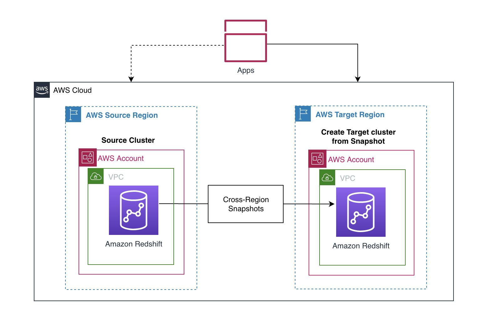
The following diagram illustrates the architecture for cross-Region migration within the same AWS account.

The solution includes the following steps:

  1. Configure cross-Region snapshots of the source Amazon Redshift cluster before the cutover deadline.
  2. Restore the latest snapshots to create a new Amazon Redshift cluster in the target Region.
  3. Point your applications to the new Amazon Redshift cluster.

For encrypted snapshots, there is an additional step of creating a new encryption key and performing a snapshot grant before you can copy the snapshot to the target Region.

Prerequisites

For the migration process, select a maintenance window during when there is low write activity, and be aware of the RTO and RPO requirements of the organization.

The following steps walk you through setting up an Amazon Redshift cluster in the source Region and populating it with a sample dataset. For this post, we use US West (Oregon) as the source Region and US East (N. Virginia) as the target Region. If you already have a source Amazon Redshift cluster, you can skip these prerequisite steps.

Create an Amazon Redshift cluster in the source Region

To create your cluster in the source Region, complete the following steps:

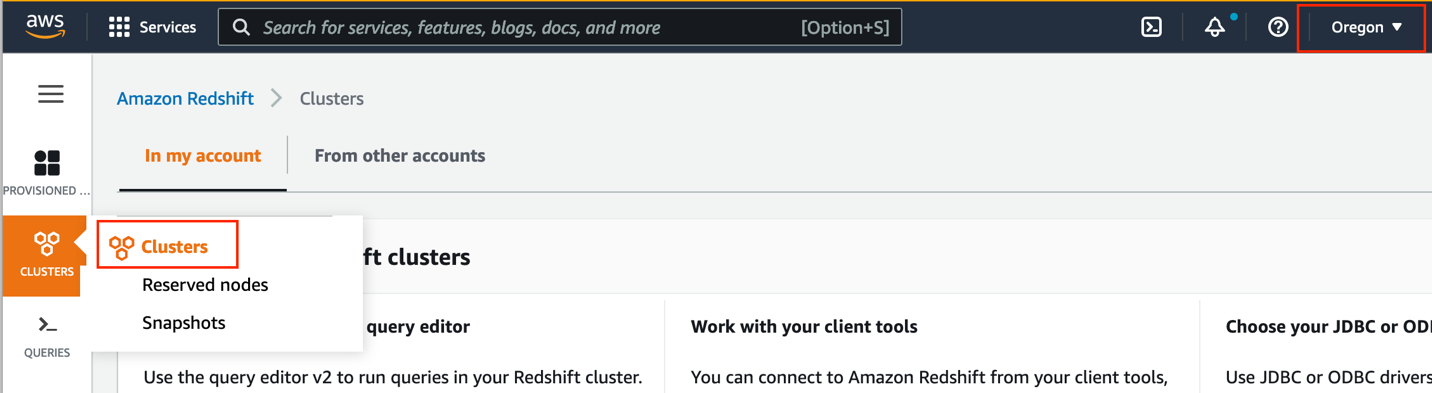
  1. Open the Amazon Redshift console in your source Region.
  2. Choose Clusters in the navigation pane and choose Clusters again on the menu.
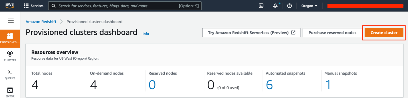
  3. Choose Create cluster.
  4. For Cluster identifier, enter redshift-cluster-source.
  5. Select Production for cluster use.

This option allows you to select specific instance types and load the sample data of your choice. Note that you are charged for Amazon Redshift instances and storage for the entire time until you delete the cluster. For more information about pricing, see Amazon Redshift pricing.

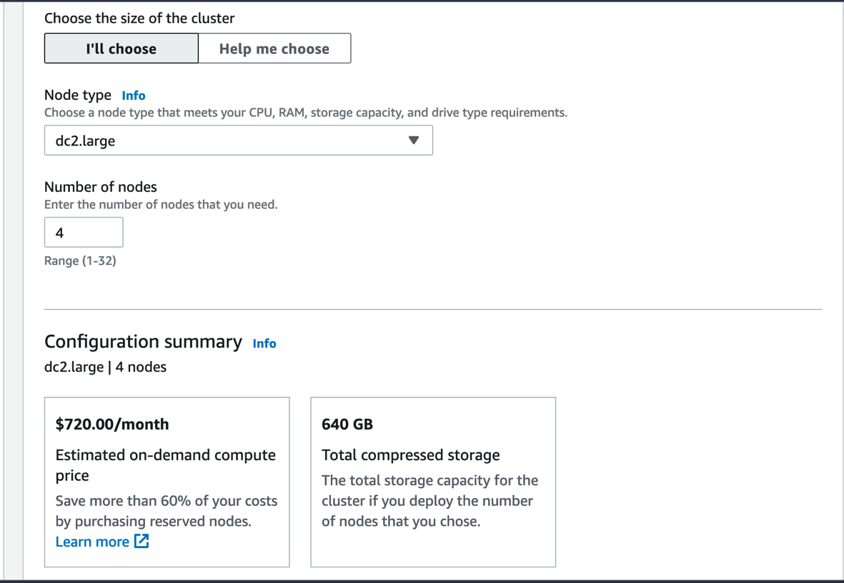
  1. For Node type, choose your preferred node type.
  2. For Number of nodes, enter the number of nodes to use.

For this post, we use four dc2.large instances.

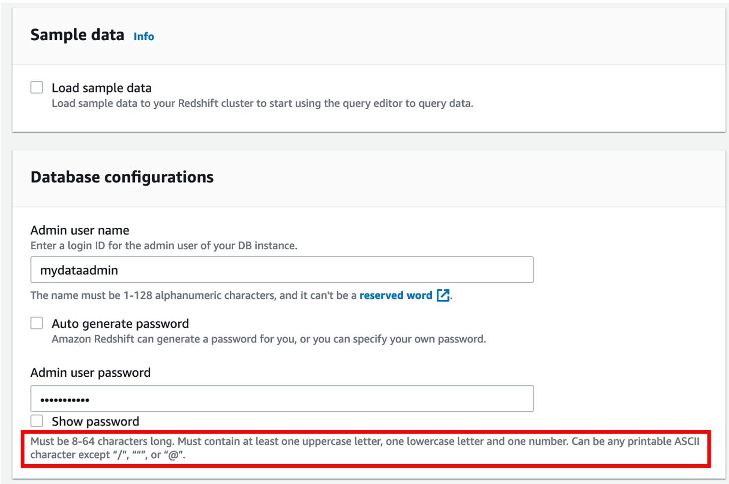
  1. Under Database configurations, enter a user name and password for the cluster.

As a best practice, change the default user name to a custom user name (for this post, mydataadmin) and follow the password guidelines.

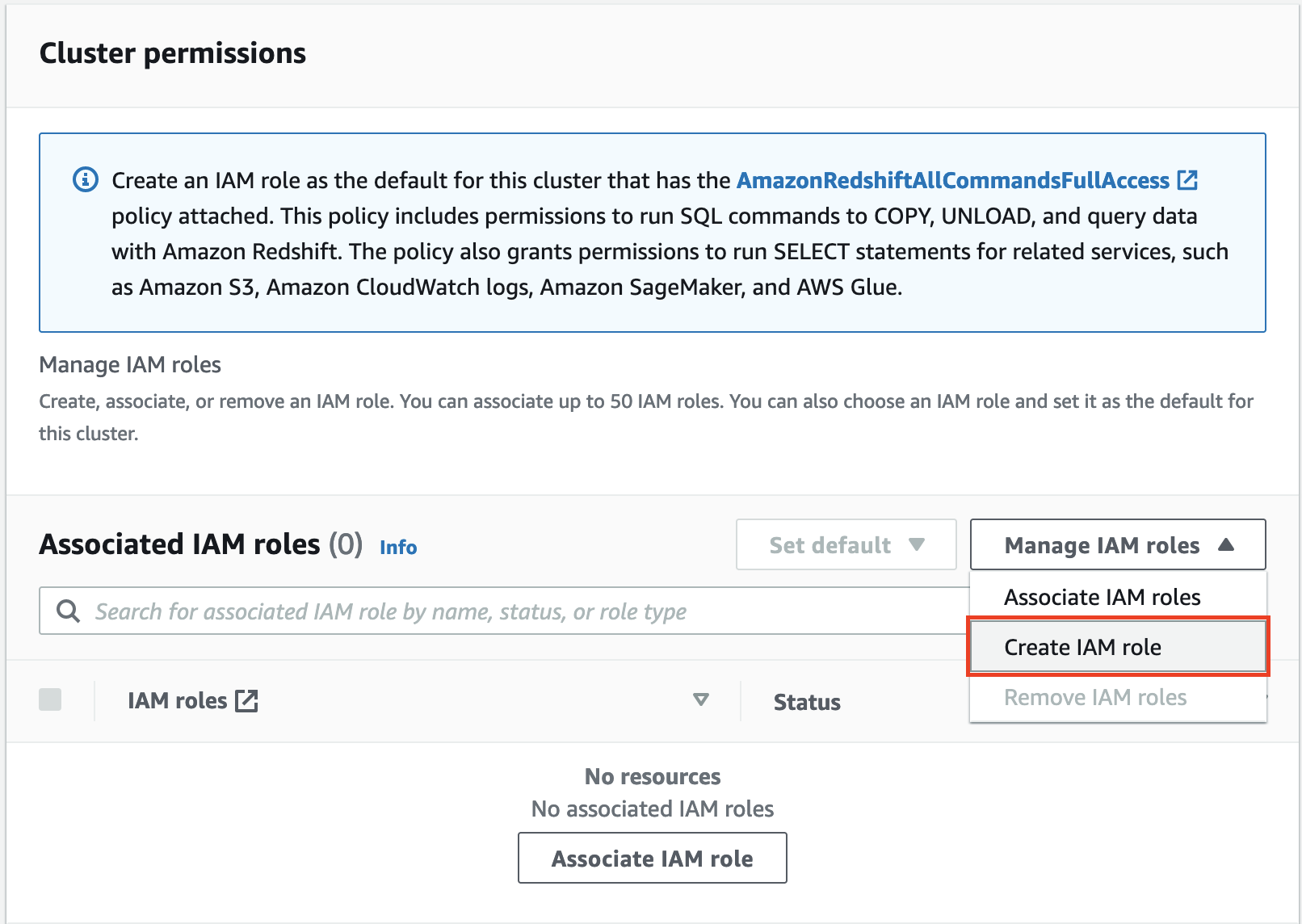
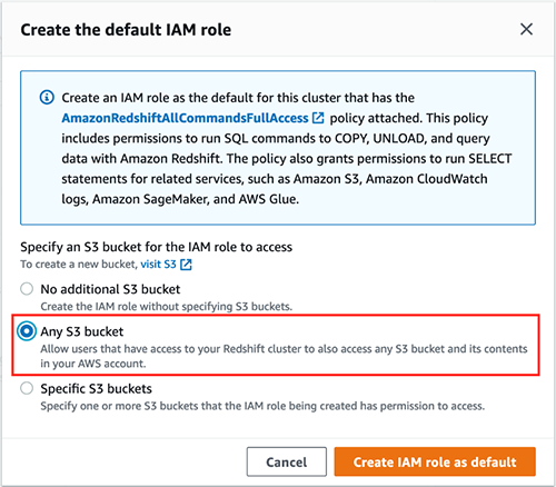
To load the sample data from an external Amazon Simple Storage Service (Amazon S3) bucket to the source cluster, you need to create an AWS Identity and Access Management (IAM) role.

  1. Under Cluster permissions, on the Manage IAM roles drop-down menu, choose Create IAM role.
  2. Select Any S3 bucket and choose Create IAM role as default.
  3. For Additional configurations, turn Use defaults off.
  4. In the Network and security section, choose a VPC and cluster subnet group.

For more information about creating a cluster, refer to Creating a cluster in a VPC.

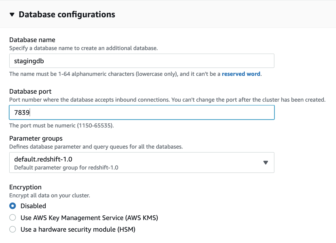
  1. Expand Database configurations.

We recommend using custom values instead of the defaults.

  1. For Database name, enter stagingdb.
  2. For Database port, enter 7839.
  3. For Encryption, select Disabled.
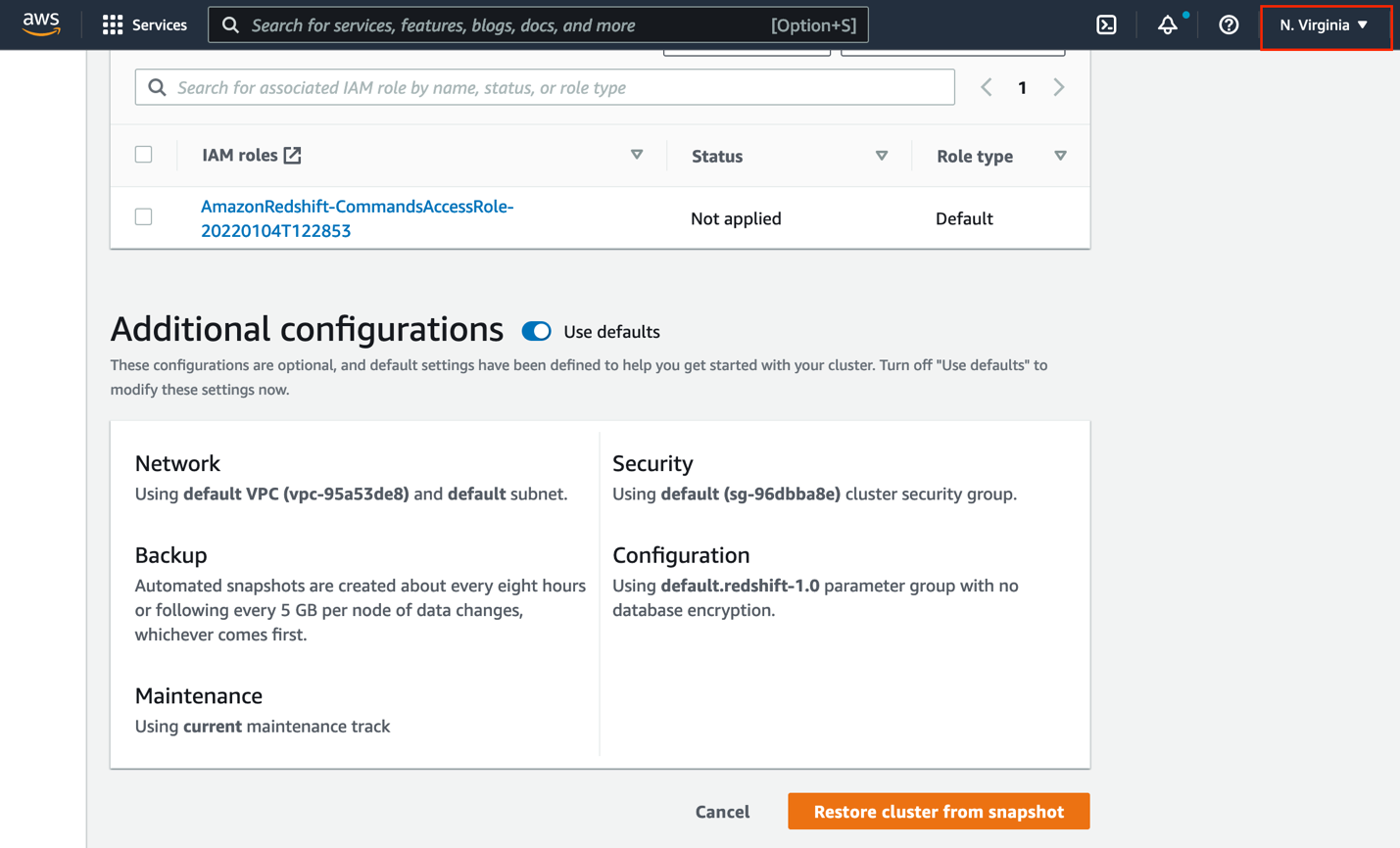
We enable encryption in a later step.

  1. Leave the other options as default and choose Create cluster.
  2. When the cluster is available, enable audit logging on the cluster.

Audit logging records information about connections and user activities in your database. This is useful for security as well as troubleshooting purposes.

To meet security best practices, you also create a new Amazon Redshift parameter group.

  1. Choose Configurations and Workload management to create your parameter group.
  2. Make sure that the parameters require_ssl and enable_user_activity_logging are set to true.
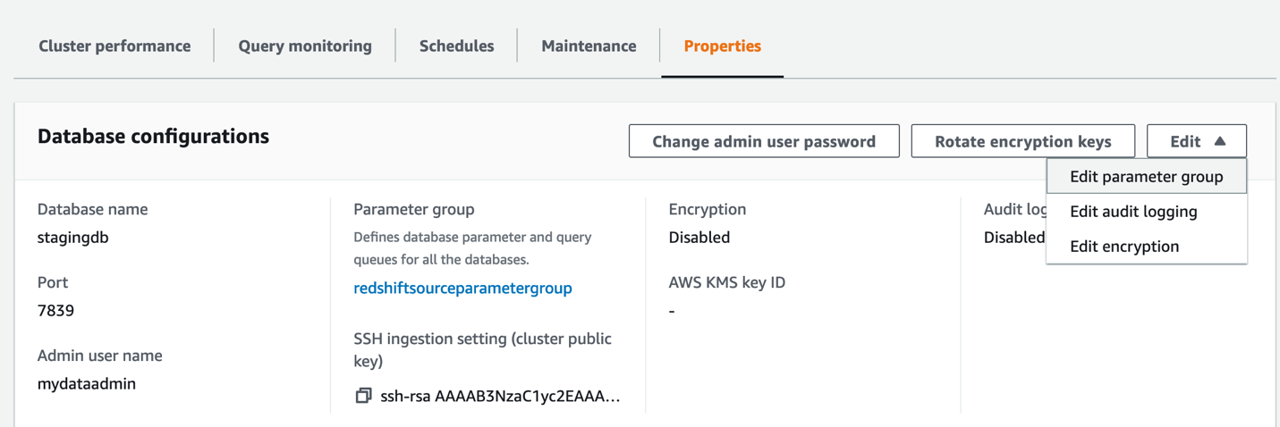
  3. On the Properties tab, choose the Edit menu in the Database configurations section and choose Edit parameter group.
  4. Associate the newly created parameter group to the Amazon Redshift cluster.

If this change prompts you to reboot, choose Reboot.

Load the sample dataset in the source Amazon Redshift cluster

When the cluster is ready, it’s time to load the sample dataset from the S3 bucket s3://redshift-immersionday-labs/data/. The following tables are part of the dataset:

  • REGION (5 rows)
  • NATION (25 rows)
  • CUSTOMER (15 million rows)
  • ORDERS (76 million rows)
  • PART (20 million rows)
  • SUPPLIER (1 million rows)
  • LINEITEM (600 million rows)
  • PARTSUPPLIER (80 million rows)

It’s a best practice for the Amazon Redshift cluster to access the S3 bucket via VPC gateway endpoints in order to enhance data loading performance, because the traffic flows through the AWS network, avoiding the internet.

Before we can load our data into Amazon S3, we need to enable a VPC endpoint via Amazon Virtual Private Cloud (Amazon VPC).

  1. On the Amazon VPC console, choose Endpoints.
  2. Choose Create endpoint.
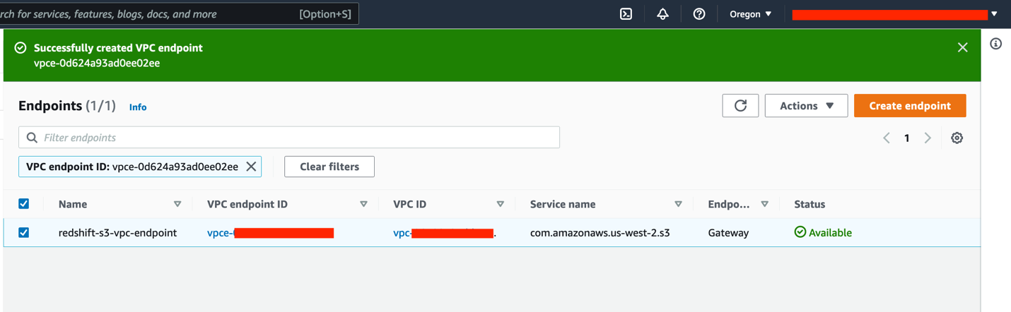
  3. For Name tag, enter redshift-s3-vpc-endpoint.
  4. For Service category, select AWS services.
  5. Search for S3 and select the Gateway type endpoint.
  6. Choose the same VPC where your cluster is provisioned and select the route table.
  7. Leave everything else as default and choose Create endpoint.

Wait for the Gateway endpoint status to change to Available.

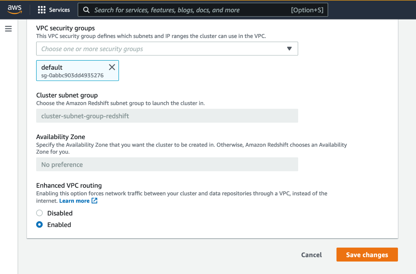
Next, you enable enhanced VPC routing.

  1. Open the Amazon Redshift console in the source Region.
  2. Choose your source cluster.
  3. On the Properties tab, in the Network and security settings section, choose Edit.
  4. For Enhanced VPC routing, select Enabled.
  5. Choose Save changes.

Wait for the cluster status to change to Available.

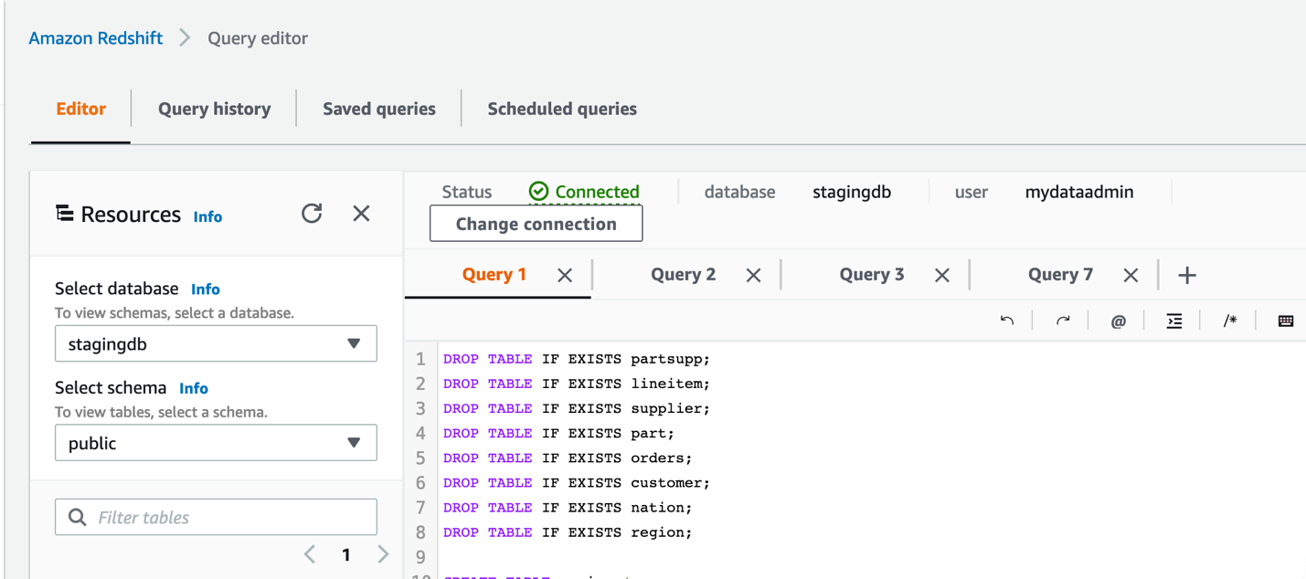
You need to create tables in order to load the sample data into the cluster. We recommend using the Amazon Redshift web-based query editor.

  1. On the Amazon Redshift console, choose Editor in the navigation pane and choose Query editor.

You can also use the new query editor V2.

  1. Choose Connect to database.
  2. Select Create new connection.
  3. Enter the database name and user name.
  4. Choose Connect.

For this post, we use the TPC data example from the Amazon Redshift Immersion Labs.

  1. Navigate to the Data Loading section of the Immersion Day Labs.
  2. Follow the instructions in the Create Tables section to create the tables in your source cluster.
  3. After you create the tables, follow the instructions in Loading Data section to load the data into the cluster.

Loading the data took approximately 17 minutes in the US West (Oregon) Region. This may vary depending on the Region and network bandwidth at that point in time.

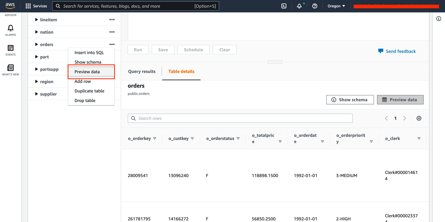
After the data is loaded successfully into the source cluster, you can query it to make sure that you see the data in all the tables.

  1. Choose a table (right-click) and choose Preview data.
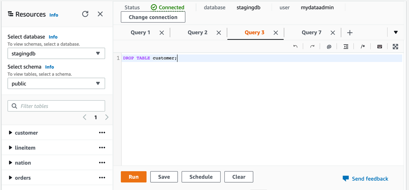
  2. Drop the customer table using the query DROP TABLE customer;.

We add the table back later to demonstrate incremental changes.

You can check the storage size to verify the size of the data loaded.

  1. Choose Clusters in the navigation pane.
  2. Choose your source cluster.
  3. Verify the storage size in the General information section, under Storage used.

Your source Amazon Redshift cluster is now loaded with a sample dataset and is ready to use.

Configure cross-Region snapshots in the source Region

To perform inter-Region migration, the first step is to configure cross-Region snapshots. The cross-Region snapshot feature enables you to copy over snapshots automatically to another Region.

  1. Open the Amazon Redshift console in the source Region.
  2. Select your Amazon Redshift cluster.
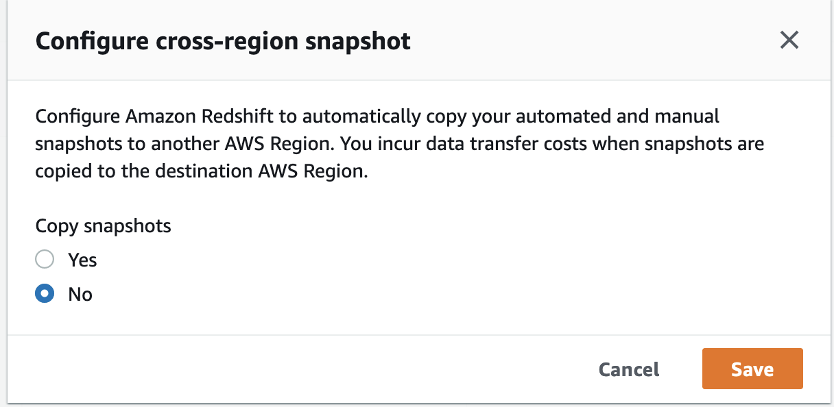
  3. On the Actions menu, choose Configure cross-region snapshot.
  4. For Copy snapshots, select Yes.
  5. For Destination Region, choose your target Region (for this post, us-east-1).
  6. Configure the manual snapshot retention period according to your requirements.
  7. Choose Save.

After the cross-Region snapshot feature is configured, any subsequent automated or manual snapshots are automatically copied to the target Region.

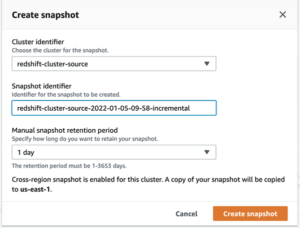
  1. To create a manual snapshot, choose Clusters in the navigation pane and choose Snapshots.
  2. Choose Create snapshot.
  3. For Cluster identifier, choose redshift-cluster-source.
  4. Adjust the snapshot retention period based on your requirements.
  5. Choose Create snapshot.

The idea is to take multiple snapshots until the cutover deadline so as to capture as much data as possible for minimal data loss based on your RTO and RPO requirements. The first snapshot creation took about 4 minutes for 28.9 GB of data, but subsequent snapshots are incremental in nature.

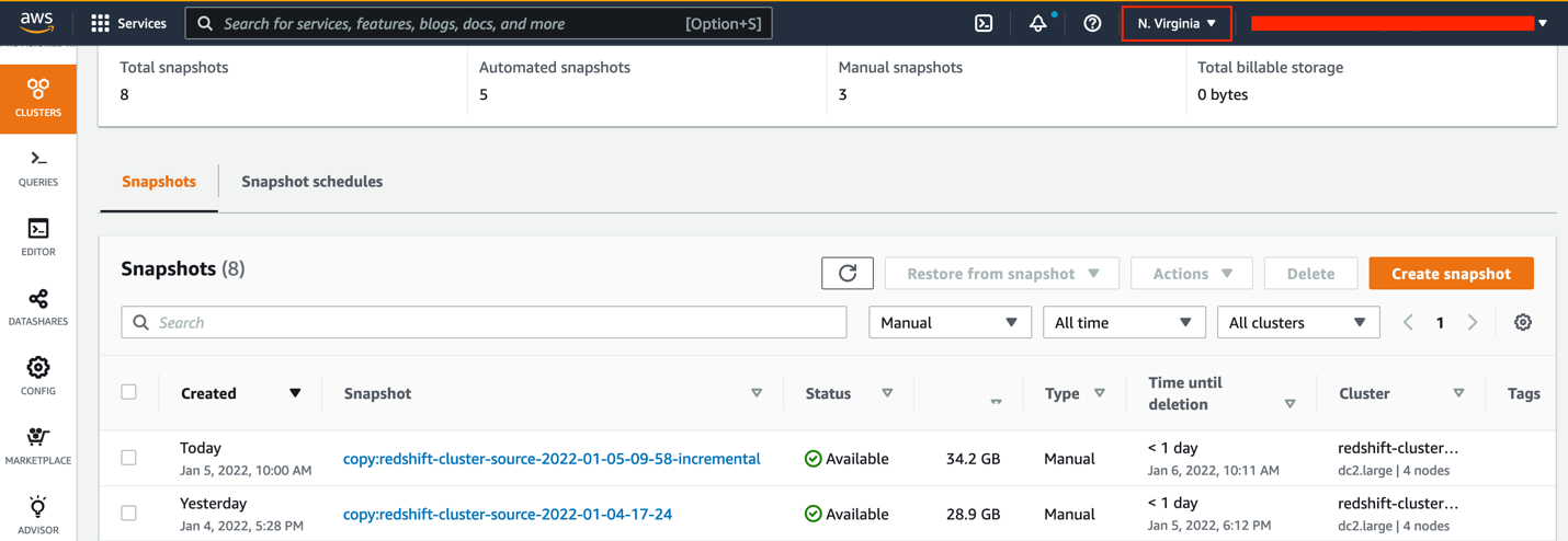
This snapshot gets automatically copied to the target Region from the source Region. You can open the Amazon Redshift console in the target Region to verify the copy.

As shown in the following screenshot, the snapshot of size 28.9 GB took around 44 minutes to get copied to the target Region because it’s the first snapshot containing all the data in the cluster. Depending on the Regions involved and the amount of data to copy, a cross-Region snapshot copy may take hours to complete.

Let’s now simulate incremental changes being made to the source cluster.

  1. Open the Amazon Redshift console in the source Region and open the query editor.
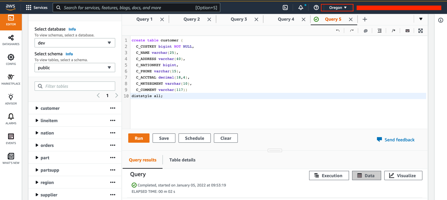
  2. Create a new table called customer in the cluster using the following query:
    create table customer (
      C_CUSTKEY bigint NOT NULL,
      C_NAME varchar(25),
      C_ADDRESS varchar(40),
      C_NATIONKEY bigint,
      C_PHONE varchar(15),
      C_ACCTBAL decimal(18,4),
      C_MKTSEGMENT varchar(10),
      C_COMMENT varchar(117))
    diststyle all;

  3. Load data into the customer table using the following command:
    copy customer from 's3://redshift-immersionday-labs/data/customer/customer.tbl.'
    iam_role default
    region 'us-west-2' lzop delimiter '|' COMPUPDATE PRESET;

  4. To create a manual snapshot containing incremental data, choose Clusters in the navigation pane, then choose Snapshots.
  5. Provide the necessary information and choose Create snapshot.

Because the cross-Region snapshot functionality is enabled, this incremental snapshot is automatically copied to the target Region. In the following example, the snapshot took approximately 11 minutes to copy to the target Region from the source Region. This time varies from Region to Region and is based on the amount of data being copied.

Restore snapshots to same or higher instance types in the target Region

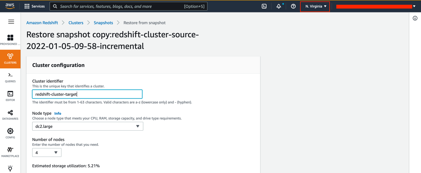
When the latest snapshot is successfully copied to the target Region, you can restore the snapshot.

  1. Open the Amazon Redshift console in the target Region.
  2. On the Snapshots page, select your snapshot.
  3. On the Restore from snapshot menu, choose Restore to a provisioned cluster.
  4. For Cluster identifier, enter redshift-cluster-target.
  5. For Node type¸ you can use the same instance type or upgrade to a higher instance type.
  6. For Number of nodes, choose the number of nodes you need.

If you choose to upgrade your instance to RA3, refer to Upgrading to RA3 node types to determine the number of nodes you need.

For this post, we still use four nodes of the dc2.large instance type.

  1. Under Database configurations, for Database name¸ enter stagingdb.
  2. Leave the rest of the settings as default (or modify them per your requirements) and choose Restore cluster from snapshot.

A new Amazon Redshift cluster gets provisioned from the snapshot in the target Region.

Follow the same security best practices that you applied to the source cluster for the target cluster.

Point your applications to the new Amazon Redshift cluster

When the target cluster is available, configure your applications to connect to the new target Amazon Redshift endpoints. New clusters have a different Domain Name System (DNS) endpoint. This means that you must update all clients to refer to the new endpoint.

Inter-Region migration steps for encrypted data

If the data in your Amazon Redshift cluster is encrypted, you need to perform additional steps in your inter-Region migration. If data encryption is already enabled, you can skip to the steps for snapshot copy grant.

Enable data encryption in the source Amazon Redshift cluster

To enable data encryption in the source cluster, we use Amazon Key Management Service (AWS KMS).

  1. Open the AWS KMS console in the source Region.
  2. Create a KMS key called redshift-source-key.
  3. Enable key rotation.
  4. On the Amazon Redshift console (still in the source Region), select your cluster.
  5. If a cross-Region snapshot is enabled, choose Configure cross-region snapshot on the Actions menu.
  6. Select No and choose Save.
  7. On the Properties tab, in the Database configurations section, choose the Edit menu and choose Edit encryption.
  8. Select Use AWS Key Management Service (AWS KMS).
  9. Select Use key from current account and choose the key you created.
  10. Choose Save changes.

The time taken to encrypt the data is based on the amount of data present in the cluster.

If the data is encrypted, any subsequent snapshots are also automatically encrypted.

Snapshot copy grant

When you copy the encrypted snapshots to the target Region, the existing KMS key in the source Region doesn’t work in the target Region because KMS keys are specific to the Region where they’re created. You need to create another KMS key in the target Region and grant it access.

  1. Open the AWS KMS console in the target Region.
  2. If you don’t already have a KMS key to use, create a key called redshift-target-key.
  3. Enable key rotation.
  4. Open the Amazon Redshift console in the source Region.
  5. Select the cluster and on the Actions menu, choose Configure cross-region snapshot.
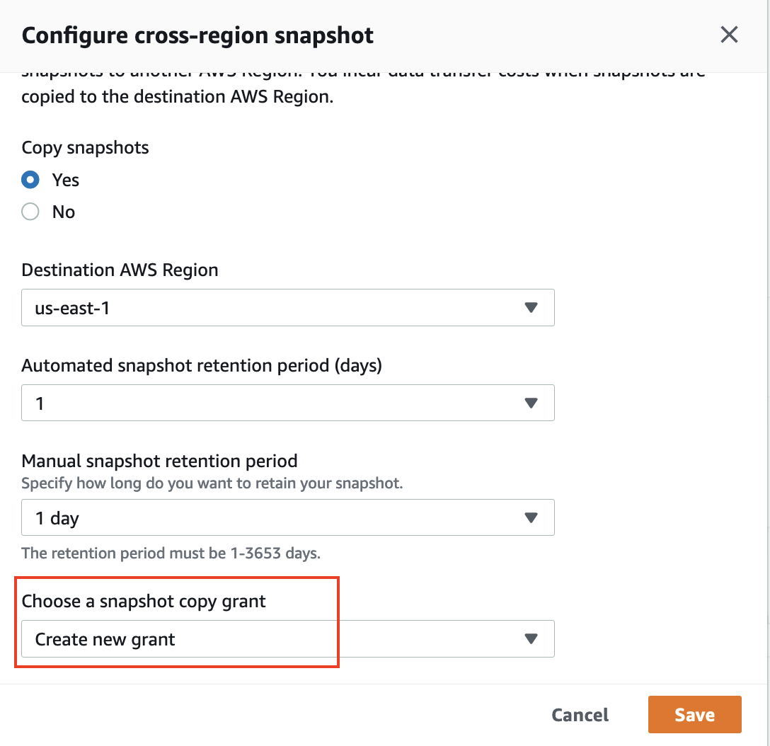
  6. For Copy snapshots, select Yes.
  7. For Choose a snapshot copy grant, choose Create new grant.
  8. For Snapshot copy grant name, enter redshift-target-grant.
  9. For KMS key ID, choose the key that you created for the grant.

If you don’t specify a key ID, the grant applies to your default key.

  1. Choose Save.

Any subsequent snapshots copied to the target Region are now encrypted with the key created in the target Region.

  1. After the snapshot is copied to the target Region, restore the cluster from the encrypted snapshot, following the steps from earlier in this post.

For more details on the encryption process, refer to Copying AWS KMS–encrypted snapshots to another AWS Region.

After you restore from the encrypted snapshot, the restored cluster is automatically encrypted with the key you created in the target Region.

Make sure that your applications point to the new cluster endpoint when the cluster is available.

Clean up

If you created any Amazon Redshift clusters or snapshots for testing purposes, you can delete these resources to avoid incurring any future charges.

For instructions on deleting the snapshots, refer to Deleting manual snapshots.

For instructions on deleting the Amazon Redshift cluster, refer to Deleting a cluster.

Conclusion

This post showed how to migrate your Amazon Redshift cluster to another Region using the cross-Region snapshot functionality. Amazon Redshift migration requires some prior planning depending on the Regions involved and the amount of data to copy over. Snapshot creation and copying may take a significant amount of time. The first snapshot contains all the data in the cluster and therefore it may take longer, but subsequent snapshots contain incremental changes and may take less time depending on the changes made. It’s a good idea to estimate how much time the snapshot copy takes by performing some tests in your staging environments with snapshots of a similar size or slightly larger than the ones in the production environment so you can plan for minimal data loss and meet RTO and RPO requirements.

For further details about the Amazon Redshift snapshot functionality, refer to Working with Snapshots.


About the Author

Sindhura Palakodety is a Solutions Architect at Amazon Web Services. She is passionate about helping customers build enterprise-scale Well-Architected solutions on the AWS platform and specializes in Containers and Data Analytics domains.