All posts by Brianna Rosentrater

Planning for disaster recovery using AWS Local Zones and AWS Outposts racks

Post Syndicated from Brianna Rosentrater original https://aws.amazon.com/blogs/compute/planning-for-disaster-recovery-using-aws-local-zones-and-aws-outposts-racks/

AWS customers with data residency, low latency, or local data processing requirements can use AWS Hybrid Cloud services to run their workloads either on-premises or within their regulatory boundary. Many of these workloads might be critical to their business, with minimal thresholds for downtime.

This post provides practical design guidance for building highly available architectures that span either two AWS Outposts racks or an Outpost rack and an AWS Local Zone, which are physically designed without single points of failure. By distributing workloads across two geographically and logically independent edge locations, you can achieve high availability while still benefiting from the low-latency, data-residency, and on-premises integration advantages that edge infrastructure provides. To maintain high availability, we recommend that you put a disaster recovery (DR) plan in place and conduct regular DR drills with your applications.

The architectures presented here cover a range of approaches to failure detection and site switching. Each approach offers a different balance between Recovery Time Objective (RTO) and Recovery Point Objective (RPO), operational complexity, and cost. By understanding these trade-offs, you can select the architecture that best aligns to your RPO/RTO targets, data protection and residency requirements, and budget. This helps you achieve the resilience your business requires without over-engineering or over-spending.

Overview

Outposts and Local Zones function as extensions of a single Availability Zone (AZ) within the AWS Region they’re anchored to. For high availability when planning for failover between the two platforms, anchor each to a different parent Region or, at minimum, a different AZ within the same Region. This geographic separation supports the low RPO and RTO targets required for mission-critical workloads. The architectures in this post follow these principles:

  • Shared responsibility: AWS manages the Outposts and Local Zone infrastructure. You provide resilient power, cooling, and network connectivity for Outpost sites, and implement application-level failover logic.
  • Independent failure domains: Treat each site as an independent failure domain. Anchoring each to a different parent AZ (or Region) ensures a failure in one AZ doesn’t affect both sites.
  • Resilient network connectivity: Local Zones connect to their parent Region through the AWS Global Network, designed for maximum resilience. Outpost racks include redundant Outpost Networking Devices (ONDs) with eBGP peering for multipath load balancing and failover.
  • Capacity planning for N+1: Provision additional capacity beyond your expected workload so surviving instances can absorb the load during host failures without degradation.

Building blocks of a disaster recovery strategy

A key design consideration is how quickly the architecture can detect a site failure and redirect traffic, and what layers of your workload need protection. Your RPO and RTO needs govern this requirement. This post covers three approaches to disaster recovery at different layers of your application, each offering a different balance between time-to-recovery and operational complexity:

  1. Active/passive DNS-based failover with Amazon Route 53 health checks.
  2. Active/active architecture using physical or virtual load balancers deployed at each site.
  3. Hybrid database recovery using native database engine replication with Amazon Relational Database Service (Amazon RDS).

Depending on your workload, you can implement a combination of these strategies to support the various layers of compute and storage of your application.

Active/passive DNS-based failover with Amazon Route 53 health checks

If your workload consists of on-premises web servers accessible from the internet or internal network, you can use a DNS-based failover approach to reroute traffic to a healthy web server in the event of a hardware failure or site outage. Although this method supports any DNS service, the following architecture example uses Amazon Route 53.

DNS-based failover supports two primary approaches. The first is health check routing, where DNS resolves requests to the IP address of a known good service endpoint. The second is multi-value routing, where the DNS service returns multiple IP addresses. Clients attempt connection to the first address and automatically fail over to subsequent addresses if the connection times out. Route 53 health checks continuously monitor endpoint availability. When a site becomes unreachable, Route 53 automatically updates DNS responses to route traffic to the surviving site. This approach is globally available and works across both Outposts and Local Zones.
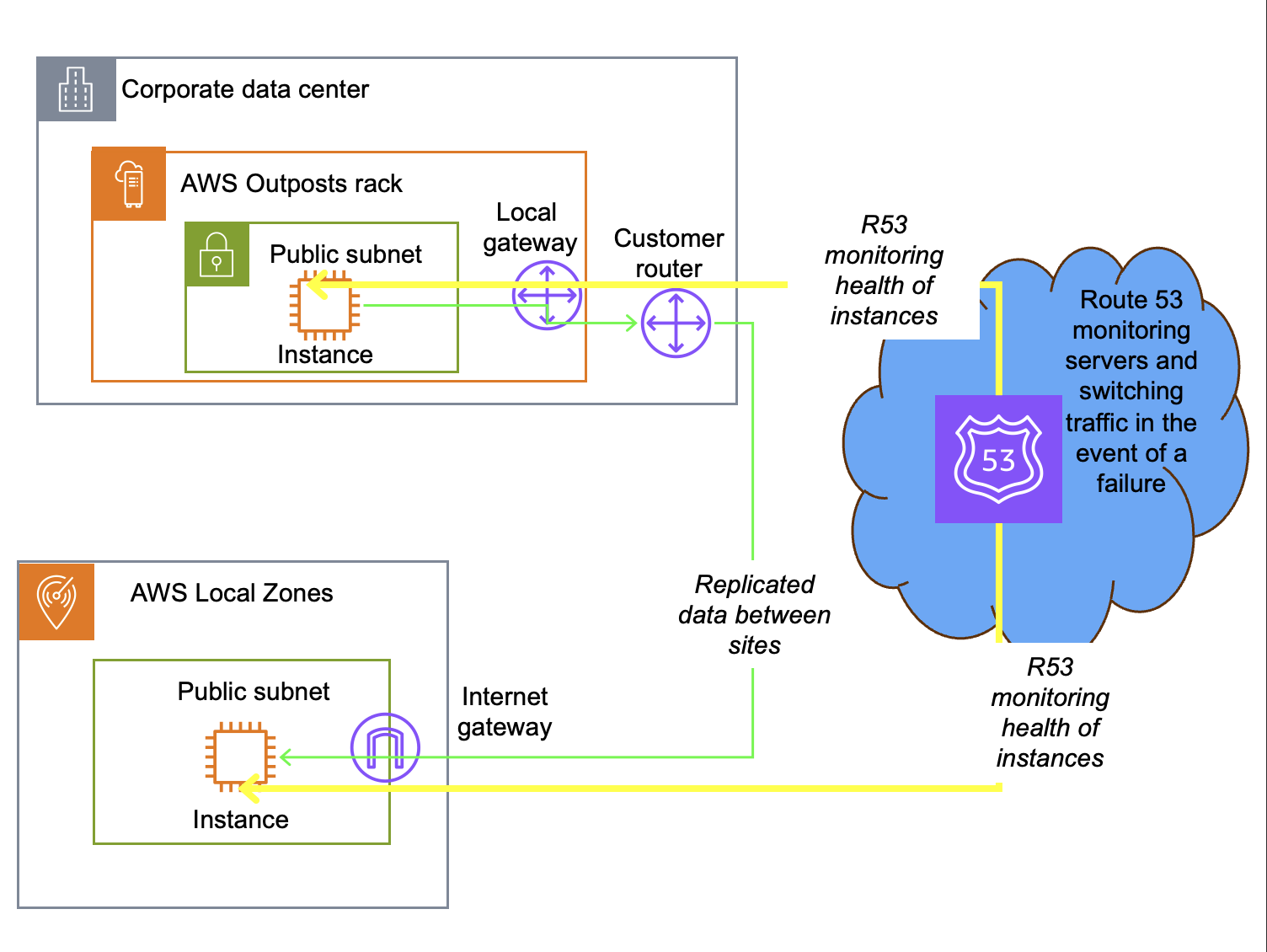
DNS-based failover architecture showing Route 53 health check monitoring, automatically routes to alternate health endpoint if primary endpoint fails health checks. This is an active/passive architecture.

Figure 1: Active/passive DNS-based failover architecture

When a specific application server fails and Route 53 determines it is unreachable, it is dynamically removed from future DNS responses. DNS systems typically have a Time to Live (TTL) of 300 seconds or longer, during which the DNS resolution is cached locally in the client. During this window, the client uses the cached IP address. New requests are automatically directed to active servers. The total recovery time is governed by the combination of the DNS TTL and health check timeout settings, typically resulting in a recovery time of 5 minutes or the TTL setting.

This design pattern works between Outposts, between an Outpost and a third-party provider, between an Outpost and a Local Zone, or between Local Zones. Route 53 can also distribute traffic across these sites, supporting blue/green deployments where you gradually shift traffic from one environment to another.

For AWS Outposts, you can configure Route 53 to monitor an endpoint in the Region. If the Outpost service link disconnects for more than 5 minutes, DNS failover routes traffic to the secondary site. The Outpost and Local Zone can be anchored to the same or different Regions for added resiliency.

As with all architectures using the public internet for replication traffic, configure Transport Layer Security (TLS) encryption in transit, security groups, and network access control lists (NACLs) to secure your data and control access to your subnet resources.

Active/active architecture using physical or virtual load balancers

For Outposts-to-Outposts high availability when your workload must remain on-premises, an alternative to DNS-based failover is an active/active architecture using physical or virtual load balancers deployed at each site. Outposts racks support Application Load Balancer (ALB) as well as third-party L4 and L7 virtual or physical load balancers. Like the DNS-based architecture pattern, you can use this strategy to support workloads that consist of on-premises web servers with low latency, data residency, or continued operations requirements.

In this model, both Outposts can simultaneously serve application traffic, with load balancers continuously monitoring the health of instances. When a failure is detected, the load balancer automatically shifts all traffic to the available Outpost without manual intervention or DNS propagation delays. Typically, the load balancers present a single IP address to service consumers and switch traffic when an endpoint is unavailable. Some load balancers can monitor load and switch traffic based on utilization to maintain response time. This design pattern is specific to Outposts, which support third-party devices connected on premises. It does not work with Local Zones, which are hosted in AWS datacenters.
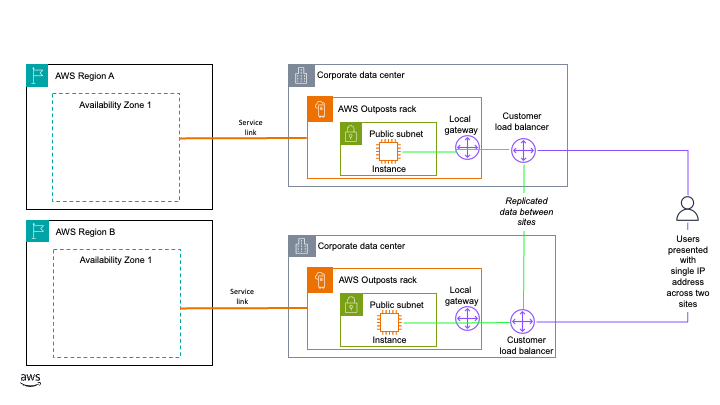
Active/active architecture using load balancers at each site with data being replicated between sites.

Figure 2: Active/active architecture using physical or virtual load balancers

When you deploy this architecture, make sure the load balancer tier itself does not become a single point of failure. Deploy redundant load balancer instances at each Outpost, with failover between them, so the traffic management layer stays available even if one load balancer instance fails. We also recommend that you configure session persistence and connection draining on your load balancers to minimize disruption to in-flight requests during failover. With this approach, load balancer instances route traffic to your Outpost instances over the local gateway of each Outpost. Traffic continues to be balanced between instances on each Outpost even if one of the Outposts loses its service link connection. You can anchor the Outposts to the same or different Availability Zones or Regions for added resiliency. This approach does require 2N infrastructure and an external load balancer, making it the most resource-intensive to implement.

Some load balancers also support multiple endpoint monitoring. The load balancer monitors both the regional instance and the local application. If the service link fails, based on the administrator’s policy, it can drain connections and route traffic to the other Outpost. This keeps service status and logging fully available on the connected Local Zone or Outpost.

Hybrid database recovery using native database engine replication

If you have two or more logical Outpost racks, you can deploy Amazon RDS on AWS Outposts with Multi-AZ high availability. However, depending on your workload criticality, number of sites, and site locations, a more cost-effective disaster recovery option using one Outpost, one Local Zone, or both might be appropriate. For applications that require a database, you can use your chosen database engine’s native replication features or third-party tooling to create hybrid database architectures across an Outpost and a Local Zone, an Outpost and the Region, or a Local Zone and the Region. If using the Region for failover, this can be the same Region your Outpost or Local Zone is anchored to, or a different Region of your choosing. Limitations based on your chosen database engine and licensing terms apply. In this post, all architecture patterns use a PostgreSQL database. The following three hybrid database strategies expand on the hybrid database with Amazon RDS and AWS Outposts architecture to show how this design pattern supports disaster recovery across Outposts, Local Zones, and AWS Regions.

These architectures use a bring-your-own-license (BYOL) model. The replica instance used for high availability and disaster recovery (HA/DR) is customer-managed, running on Amazon Elastic Compute Cloud (Amazon EC2) and Amazon Elastic Block Store (Amazon EBS). The primary database instance can also be customer-managed, or it can be an RDS-managed database instance so you can use a managed service as your primary operating model. Promoting a replica to primary after a failure is a manual process, but you can automate it with infrastructure as code. Promotion requires updating your DNS entry for the database instance.
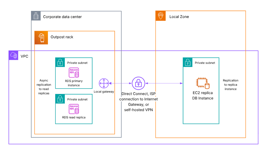
Architecture diagram showing database failover from an Outpost rack to a Local Zone. RDS can only run on 1 platform (Outposts, Local Zones, or in Region) and does not support RDS-native read replicas across platforms. Some database engines support native replication features, and customers can implement a self-managed replica using EC2 and EBS.

Figure 3: Database failover from an Outpost rack to a Local Zone

In the preceding diagram (Figure 3), the Outpost and the Local Zone can be in the same or different Regions for added resiliency.

In the following diagram (Figure 4), replication traffic can use either the service link or the local gateway of the Outpost as its network path. Replication continues through the local gateway even if the service link fails. If using the service link, the EC2 replica database instance must be in the Outpost anchor Region. If using the local gateway, the EC2 replica database instance can be in the same Region as or a different Region from the Outpost anchor Region for added resiliency. You need to configure a Virtual Private Gateway, Transit Gateway, or Internet Gateway in the Region to receive the replication traffic from the Outpost.
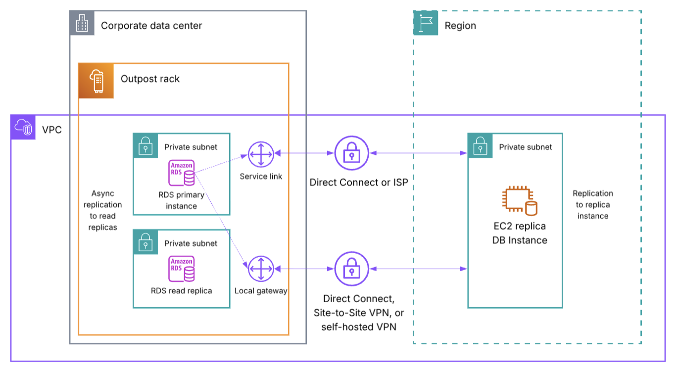
Architecture showing database failover from an Outpost rack to an AWS Region. RDS can only run on 1 platform (Outposts, Local Zones, or in Region) and does not support RDS-native read replicas across platforms. Some database engines support native replication features, and customers can implement a self-managed replica using EC2 and EBS.

Figure 4: Database failover from an Outpost rack to an AWS Region

In the following diagram (Figure 5), both the primary database instance and the replica are self-hosted on EC2 and EBS. Check your specific Local Zone location for currently supported services to see if the primary database instance can use RDS. The Region used for the EC2 replica DB instance can be the same Region the Local Zone is a part of, or a different Region for added resiliency. If using a different Region, additional networking such as an Internet Gateway is required.
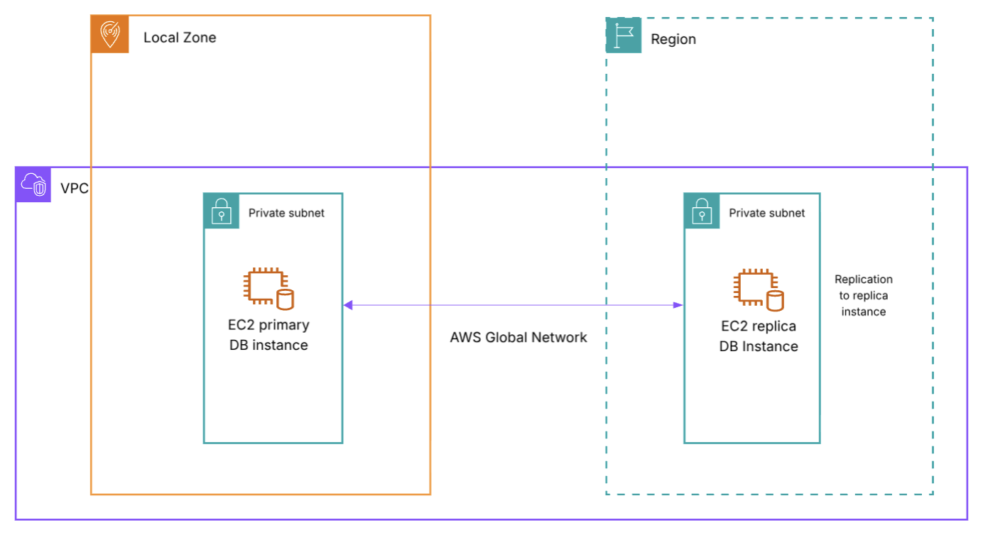
Architecture showing database failover from a Local Zone to an AWS Region. Both the primary and Region database and replica instances are customer-managed using EC2 with EBS.

Figure 5: Database failover from a Local Zone to an AWS Region

In all three architectures, you need to update your DNS records and routing to complete failover to the secondary location. If your workload requires data residency, consider whether you can use an AWS Region as a failover destination.

Disaster recovery overview

The strategies discussed in this post support different RTO/RPO objectives. Recovery time depends on the amount of effort to redeploy or reroute to an alternate environment, and whether this process is manual or automated. Recovery point depends on whether the workload has persistent data that needs to be replicated, whether that replication happens synchronously or asynchronously, and whether you use a backup and restore approach. The following table is a high-level overview of the RTO/RPO you can expect for each approach based on these factors:

Architecture RTO RPO
Active/passive DNS-based failover Total failover time = DNS TTL + (health check interval x failure threshold) Equal to replication schedule, or backup interval
Active/active with load balancers Seconds, traffic is already being routed to both environments Seconds, data is already being synchronously replicated between sites
Hybrid database (same anchor Region) Minutes, time needed to reroute to replica instance Equal to replication schedule, faster replication window expected for data traveling less distance
Hybrid database (different anchor Region) <1 hour, time needed to reroute to replica instance Equal to replication schedule, longer replication window expected for data traveling a greater distance

Table 1: RTO/RPO disaster recovery overview for each architecture

For the active/passive DNS-based failover architecture, DNS TTL, Route 53 health check interval, and failure threshold are all settings you configure to your preferences. The default Route 53 health check interval is 30 seconds, but can be set as low as 10 seconds. The default Route 53 failure threshold is 3 failed checks, but can be set to any number between 1 to 10. Generally, active/active architectures provide the lowest RTO/RPO for your workloads, whereas active/passive architectures incur some downtime during a disaster when rerouting user traffic to your passive standby environment. Review your workload RTO/RPO objectives to determine which approach is right for you. You might require different strategies for different tiers of workload based on your threshold for downtime at each tier.

Considerations

When choosing a disaster recovery strategy, consider:

  • Latency impact based on the location of your failover site and where your application users are.
  • Resilient network connectivity between your primary and secondary failover locations, or between your on-premises site and the AWS Region. Architecture-specific guidance is included in each section.
  • If your workload requires data residency, evaluate if a particular disaster recovery approach can be used.
  • Promoting a replica (either RDS-managed or customer-managed) is a manual process that you can automate with infrastructure as code, and it requires updating your DNS entry for the database instance.
  • Database replicas might support synchronous or asynchronous replication depending on the database engine. Consider your RPO objectives when evaluating the hybrid database architectures.
  • Limitations based on your chosen database engine and licensing terms apply. Consult your licensing terms and conduct failover drills to test these architecture patterns with your workloads before implementing into production.

Conclusion

This post showed different architecture patterns for disaster recovery using both Outposts and Local Zones. See Building highly resilient applications with on-premises interdependencies using AWS Local Zones for additional guidance. Reach out to your AWS account team to learn more about the hybrid edge architectures discussed in this post. To discuss Outposts with an expert on any of these topics, submit the AWS Outposts contact form. To begin using Local Zones, enable a Local Zone from your account and start experimenting.
Deploying regulated workloads on AWS Local Zones and AWS Outposts

Post Syndicated from Brianna Rosentrater original https://aws.amazon.com/blogs/compute/deploying-regulated-workloads-on-aws-local-zones-and-aws-outposts/

Customers in many industries and geographic locations have specific data sovereignty and residency objectives. AWS Local Zones and AWS Outposts are fully managed infrastructure solutions for customers that need to keep data within specific geographic boundaries and also want the scalability and innovation of cloud services. The challenge lies not only in where data resides, but in how to architect, secure, and audit these deployments effectively. Whether you’re architecting a new solution or migrating existing regulated workloads to AWS hybrid edge infrastructure, this post provides an overview of key technologies to help you build auditable and secure architectures that support your organization’s data residency objectives.

Solution framework

Building a solution for data residency deployments on AWS hybrid infrastructure requires a thoughtful, layered approach. Rather than a prescriptive solution, this post presents a flexible framework that you can adapt to your specific operational requirements.

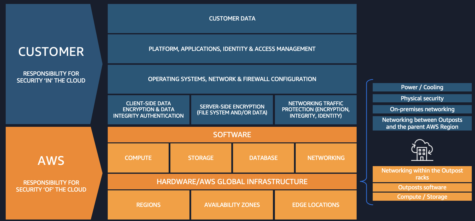
The AWS Shared Responsibility Model clearly delineates where the responsibilities of AWS end and yours begin. This model provides a critical separation: AWS controls the management infrastructure, while your data remains inaccessible to AWS operators, as enforced by the hardware-based isolation of the Nitro System. There is no operator access to the instances, applications, or data. This architectural separation provides the foundation for implementing stringent data residency controls.

To build upon this foundation, you can implement security best practices by following the guidance in the AWS Well-Architected security pillar, which helps you strengthen application-level protections and data security controls. For deeper guidance, see the Data Residency with Hybrid Cloud Services Lens, which covers considerations for operations, security, cost, performance, and reliability for regulated workloads.

When implementing data residency controls, you might need auditable evidence of traffic patterns for your internal governance processes. By using third-party monitoring tools combined with port mirroring capabilities, you can generate reports that show all traffic between your applications and databases remains within your Outpost environment. This visibility provides auditable evidence that traffic remains within your designated boundaries. You can also use AWS Artifact to access audit reports for your hybrid infrastructure.

Governance tools form the final layer of this regulatory framework, establishing guardrails around your deployment. These tools continuously monitor and enforce configuration policies, verifying that your environment stays aligned with your security and governance policies, operates within required parameters, and alerts you proactively when issues arise. This shift from reactive to proactive management helps you maintain consistent governance of your environment at scale.

Together, these layered technologies create a framework for deploying regulated workloads designed to support your data residency objectives while benefiting from the innovation and scalability of AWS services.

Shared responsibility model

When extending workloads to Local Zones and Outposts, the shared responsibility model adapts to these hybrid cloud environments while maintaining the same core principles. AWS continues to manage the underlying infrastructure and services, while you retain control over your data, applications, and configurations. This supports consistent security postures whether workloads run in AWS Regions, Local Zones, or on Outposts infrastructure. You deploy Outposts in a data center or colocation facility of your choice. Under the shared responsibility model, you are responsible for meeting site requirements for power, cooling, on-premises networking, and the Outpost service link connection to the Region. All traffic between the Outpost and the parent Region traverses an encrypted set of VPN connections over the service link, protecting communications in transit without requiring additional configuration. AWS continues to be responsible for maintaining the Outposts hardware as a managed service.

This partnership approach to security means you can build auditable solutions with data residency controls without compromising on the innovation and scalability that AWS provides.

AWS Shared Responsibility Model showing AWS responsibility for infrastructure and customer responsibility for data and configurations

Figure 1: The AWS Shared Responsibility Model in a hybrid edge deployment

AWS Nitro System

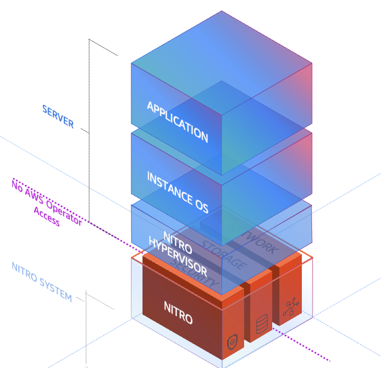
The AWS Nitro System is the virtualization platform that powers Amazon Elastic Compute Cloud (Amazon EC2) instances. It uses dedicated hardware and software to offload virtualization functions from the server CPU and delivers near-bare-metal performance. Both Outposts and Local Zones also use the Nitro System. By design, the Nitro System has no operator access. There is no way for AWS or any entity to log into the EC2 Nitro hosts, access compute resources, or reach encrypted customer data remotely. The following diagram shows the purpose-built hardware components of the Nitro System.

AWS Nitro System stack showing the Nitro Card, Nitro Security Chip, and Nitro Hypervisor components

Figure 2: The AWS Nitro System hardware and software stack

The Nitro System combines purpose-built hardware consisting of the following key security components:

  • The Nitro Card – provides I/O interfaces used for Amazon Virtual Private Cloud (Amazon VPC) network virtualization, Amazon Elastic Block Store (Amazon EBS), and instance storage, freeing up host CPU resources. Nitro Cards are logically isolated from the system main board that runs customer workloads and can be live-updated, reducing the need for maintenance windows and workload disruption.
  • The Nitro Security Chip – provides the link between the Nitro Controller (used for orchestration) and the system main board. It intercepts and controls all firmware updates, preventing the main CPUs from being used to modify system firmware. This is particularly important when running bare metal EC2 instances. This chip is also used for boot control to validate system firmware integrity.
  • The Nitro Hypervisor – designed to receive EC2 instance management commands sent by the Nitro Controller, provide compute virtualization and logical instance isolation, and assign SR-IOV virtual functions as needed. It includes no general-purpose operating system features, only the features absolutely necessary for its function, and works with other purpose-built Nitro components to maintain its small size and bare-metal-like performance. This simple design reduces the risk for remote networking attacks and driver-based privilege escalations.
  • The Nitro Security Key (Outposts only) – a removable device that stores the external key required to decrypt all data at rest on your Outpost. At the end of your Outposts commitment, after migrating your data off the Outpost, you can destroy this key to cryptographically shred any remaining data on the Outpost.

These components work together to provide a layered security approach that doesn’t compromise performance. By designing each component to have a specific function decoupled from the main system board, the Nitro System provides non-disruptive firmware updates and reduces classes of security issues often found in other hypervisor systems.

AWS Organizations Service Control Policies

AWS Organizations Service Control Policies (SCPs) are a governance tool that helps you enforce data residency requirements by controlling where resources can be created and where data can be stored or processed. SCPs function as permission guardrails that define the maximum available permissions for IAM users and roles across your organization’s accounts. By implementing deny guardrails through SCPs, you can prevent resource provisioning in unwanted locations by restricting access to AWS APIs at the infrastructure level.

When deploying regulated workloads on Local Zones and Outposts, SCPs work in conjunction with AWS Control Tower landing zones to create custom guardrails that control data movement, processing, and storage. These policies can be designed with either preventative rules (blocking actions before they occur) or detective rules (identifying compliance violations after the fact). SCPs can restrict data transfer, saving, or snapshot creation outside a specified AWS location, and they can isolate workloads to a specific location. You can apply SCPs across accounts and organizational units (OUs) within your organization. For more information, see Best practices for managing data residency in AWS Local Zones using landing zone controls and Architecting for data residency with AWS Outposts rack and landing zone guardrails.

Here’s an example SCP that restricts EC2 instance launches and network interface creation to only specified AWS Local Zone subnets:

{
    "Version": "2012-10-17",
    "Statement": [
        {
            "Sid": "DenyNotLocalZonesSubnet",
            "Effect": "Deny",
            "Action": [
                "ec2:RunInstances",
                "ec2:CreateNetworkInterface"
            ],
            "Resource": [
                "arn:aws:ec2:*:*:network-interface/*"
            ],
            "Condition": {
                "ForAllValues:ArnNotEquals": {
                    "ec2:Subnet": [
                        "arn:aws:ec2:us-west-2:123456789012:subnet/subnet-localzone1",
                        "arn:aws:ec2:us-west-2:123456789012:subnet/subnet-localzone2"
                    ]
                }
            }
        }
    ]
}

Compliance monitoring

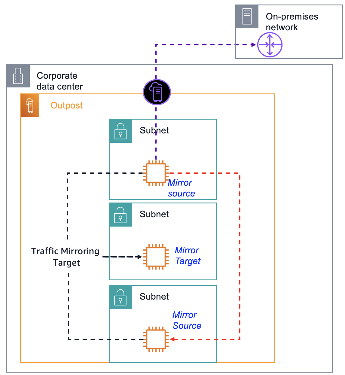
After you implement the security and governance best practices described in the preceding sections, you can demonstrate that traffic remains within your designated boundaries by using Amazon VPC Traffic Mirroring (also called port mirroring outside of AWS). This mirrors traffic between your application servers and databases. You can use a mirror target report to show that the traffic does not transit the AWS Region. For step-by-step instructions, see Get started using Traffic Mirroring to monitor network traffic. The key configuration steps include the following:

  1. Configure security groups – Allow inbound UDP port 4789 only from the security group of the source instances being mirrored, or from specific private CIDR ranges within the VPC. Do not open this port to 0.0.0.0/0.
  2. Create a traffic mirror target – Use the elastic network interface (ENI) of your monitoring instance.
  3. Create a traffic mirror filter – Define which traffic to capture, either all traffic or specific traffic.
  4. Create mirror sessions – Create one for each source instance you want to monitor. Lower session numbers are evaluated first when multiple sessions exist.
  5. Capture traffic – Use tcpdump on the target instance to analyze mirrored packets.
Amazon VPC Traffic Mirroring architecture on Outposts, mirroring traffic between application servers and databases to a monitoring instance

Figure 3: Amazon VPC Traffic Mirroring architecture on an Outpost

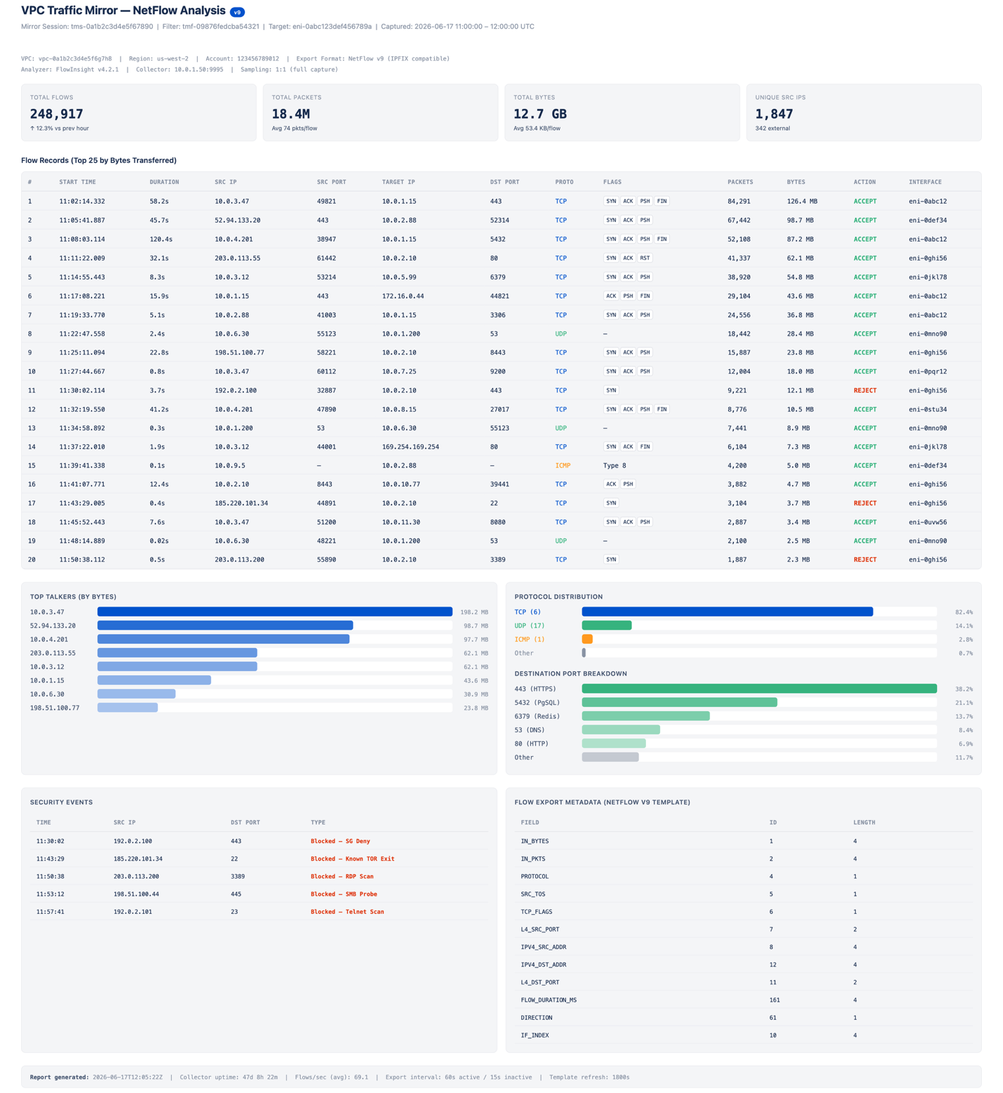
All instances must be in the same VPC, or connected through VPC peering or an AWS Transit Gateway. Traffic Mirroring encapsulates the mirrored traffic using VXLAN on UDP port 4789. Traffic Mirroring might impact network performance on source instances, so test in a development environment before deploying to production. The following image shows a sample traffic mirroring report that uses NetFlow Analyzer. For this post, all network traffic shown is simulated.

NetFlow Analyzer sample report showing traffic captured from an environment with VPC Traffic Mirroring configured

Figure 4: Sample traffic mirroring report in NetFlow Analyzer

Clean up

If you tested the VPC Traffic Mirroring architecture described in the preceding section, terminate any unnecessary resources to avoid ongoing costs. Remove the resources in the following order to avoid dependency errors:

  1. Delete the traffic mirror sessions – In the Amazon VPC console, navigate to Traffic Mirroring, Mirror Sessions. Select each mirror session you created and choose Actions, Delete. Repeat for all sessions associated with your source instances.
  2. Delete the traffic mirror filter – Navigate to Traffic Mirroring, Mirror Filters. Select the filter you created and choose Actions, Delete. You must delete all associated mirror sessions before you can delete the filter.
  3. Delete the traffic mirror target – Navigate to Traffic Mirroring, Mirror Targets. Select the target pointing to the ENI of your monitoring instance and choose Actions, Delete.
  4. Revoke security group rules – Navigate to Security Groups and select the security group attached to your monitoring instance. Remove the inbound rule that allows UDP port 4789 from the security group or CIDR range of the source instances.
  5. Terminate the monitoring instance (optional) – If you launched a dedicated EC2 instance solely for traffic capture and analysis, navigate to the EC2 console and terminate the instance. This also releases the associated ENI used as the mirror target.
  6. Delete any stored packet captures (optional) – If you saved tcpdump output to Amazon Simple Storage Service (Amazon S3) or local storage on the instance, delete those files if they are no longer needed for audit reporting.

You can verify that all Traffic Mirroring resources have been removed by running the following AWS Command Line Interface (AWS CLI) commands:

aws ec2 describe-traffic-mirror-sessions
aws ec2 describe-traffic-mirror-targets
aws ec2 describe-traffic-mirror-filters

Each command should return an empty list, confirming that no mirroring resources remain active in your account.

Conclusion

In this post, we covered how the AWS Nitro System, AWS Organizations SCPs with an AWS Control Tower landing zone, and VPC Traffic Mirroring provide capabilities for governing workloads with data residency requirements. Apply the SCP example in this post to test restricting instance launches and network interface creation to specific subnets. To learn more about Outposts for hybrid deployments, review the Getting started with AWS Outposts guide and submit the AWS Outposts contact form. To get started with Local Zones, review the Getting started with AWS Local Zones guide, opt in to a Local Zone, and begin trying some of the architecture patterns described in this post.

Architecting for IOPS and throughput performance on AWS Outposts racks

Post Syndicated from Brianna Rosentrater original https://aws.amazon.com/blogs/compute/architecting-for-iops-and-throughput-performance-on-aws-outposts-racks/

AWS Outposts extend AWS infrastructure, services, APIs, and tools to on-premises locations for workloads that require low latency, local data processing, or data residency.

In this post, you learn how to configure instances running on an Outpost to support the required IOPS and throughput for your application. The actual IOPS available to an instance is determined by the Amazon Elastic Compute Cloud (Amazon EC2) instance type selected, Amazon Elastic Block Store (Amazon EBS) storage type, and number of volumes available. The lowest performing subsystem limits your overall IOPS and throughput. This post explains each subsystem’s performance impact and provides guidance on sizing Outpost EC2 instances and storage to deliver the target IOPS and throughput values. We focus on EBS-attached volumes rather than instances using EC2 instance store storage.

Performance considerations

When designing for IOPS and high throughput, consider two main drivers with the lower value taking precedence. The first is the performance of the EC2 instances and the second is the supported IOPS and throughput of the attached EBS volumes.

At the time of publishing, Outposts supports first-generation (c5, m5, r5, g4dn) and second-generation (c7i, m7i, r7i, c8i, m8i, r8i) instance families, which are all EBS-optimized instances. These instances provide dedicated bandwidth to the EBS volume I/O, minimizing traffic contention and ensuring optimal storage performance. When attached to an EBS-optimized instance, General Purpose SSD (gp2 and gp3) volumes deliver at least 90 percent of their provisioned IOPS performance 99 percent of the time each year. For detailed instance type specifications and features, see the Amazon EC2 Instance Types Guide.

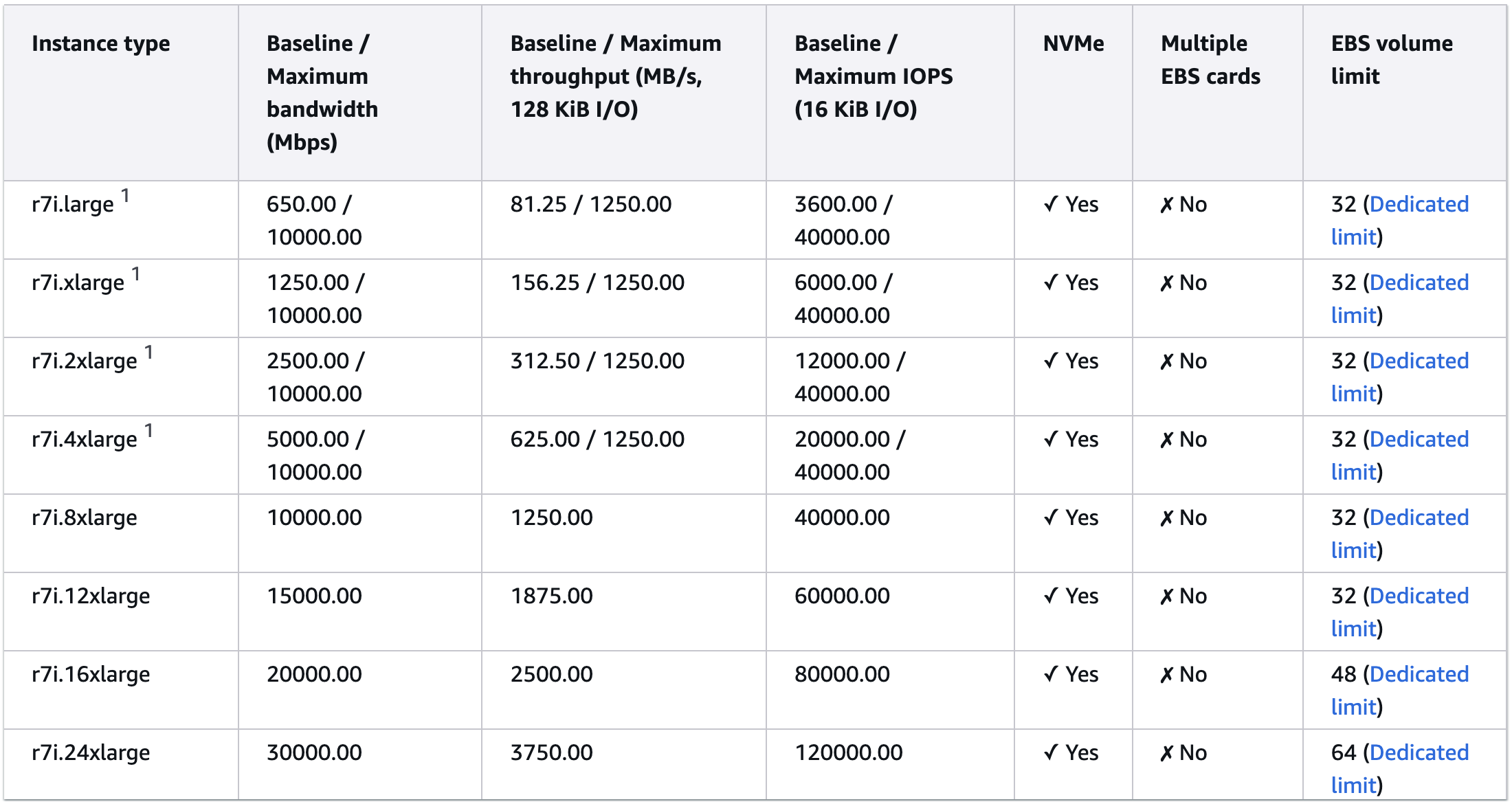
The starting point for any design is to understand the performance capability of the selected EC2 instance. Looking at Amazon EBS specifications, the columns titled “Baseline / Maximum IOPS” and “Baseline / Maximum throughput” shows the performance of memory optimized R instance family.

Memory optimized EC2 instance type IOPS performance details

1 These instances can sustain the maximum performance for 30 minutes at least once every 24 hours, after which they revert to their baseline performance.

However, your EC2 instance performance will be constrained if your attached EBS volume(s) have a lower baseline IOPS and throughput.

EBS performance

Outposts racks support two types of EBS storage: General Purpose gp2 only in first-generation Outposts racks, and General Purpose gp2 and gp3 volume types in second-generation Outposts racks. The gp2 storage type supports volumes of between 1 GiB and 16 TiB. Volumes 33.33 GiB and smaller are provisioned with the minimum of 100 IOPS, while volumes larger than 33.33 GiB are provisioned with 3 IOPS per GiB of volume size up to the maximum of 16,000 IOPS, which is reached at 5,334 GiB (3 IOPS X 5,334 GiB). See gp2 volume performance for details on how this is calculated. For gp2 volumes larger than 1,000 GiB, the baseline performance exceeds the burst performance, so burst performance becomes irrelevant. For consistent performance, we also recommend using a volume size of at least 334GiB to deliver a consistent bandwidth of 250 MiB/s, gp2 volumes deliver throughput between 128 MiB/s and 250 MiB/s depending on the volume size, with larger volumes delivering higher throughput up to maximum 250 MiB/s.

On Outposts, the gp3 storage type supports volume sizes up to 16 TiB, IOPS up to 16,000, and throughput up to 1,000 MiB/s. To reach the maximum IOPS provisioned at 500 IOPS per GiB of volume size for gp3, you must use at least a size 32 GiB volume with an EC2 instance that can also support up to 16,000 IOPS. To reach maximum throughput, your volume needs to provide at least 4,000 IOPS, which is achieved with a 8 GiB or larger volume.

Use AWS Identity and Access Management (AWS IAM) policies to control which principals can create, attach, detach, or delete EBS volumes. This is especially important when using multi-volume configurations where data spans across multiple volumes. On Outposts, Amazon EBS encryption is enabled by default — all EBS volumes are automatically encrypted at rest using AWS Key Management Service (AWS KMS) keys with no measurable impact on IOPS or throughput performance. Data is encrypted on the local NVMe storage using AES-256. For additional control, you can use AWS KMS customer-managed keys to manage the encryption keys for your volumes.

However, for the Amazon Relational Database Service (Amazon RDS) database engines supported on Outposts as well as EC2, database and EC2 instance storage is striped across multiple volumes providing several times the baseline throughput and the burst IOPS of a single volume. When small I/O operations are physically sequential, EBS attempts to merge them into a single I/O operation up to the maximum I/O size. Similarly, when I/O operations are larger than the maximum I/O size, EBS attempts to split them into smaller I/O operations. For the best performance, use larger packet sizes up to the maximum I/O size supported.

Calculating IOPS

When calculating the supported IOPS for your workload, start by choosing the instance type that supports your target IOPS, and then size the EBS both in terms of volume size and the number of attached volumes. To achieve maximum EBS performance, the combined IOPS of all attached volumes must meet or exceed the maximum IOPS supported by the instance. When selecting a general purpose EBS volume size, each GiB of EBS adds IOPS up to the maximum supported baseline IOPS (16,000 IOPS for gp2 and gp3). When designing high-performance workloads on Outposts, verify that your gp3 storage configuration is sized to meet the aggregate IOPS requirements of your workload.

As an example, the r7i.12xlarge delivers a maximum of 60,000 IOPS with an EBS throughput of 1,875 MB/s (see Figure 2). To reach this ceiling using gp2 EBS volumes — where each GiB provides 3 IOPS up to a maximum of 16,000 IOPS per volume — you would need to attach:

  • Three volumes of at least 5,334 GiB each (delivering 16,000 IOPS per volume = 48,000 IOPS combined)
  • One volume of at least 4,000 GiB (delivering the remaining ~12,000 IOPS)

This brings the total provisioned IOPS to 60,000, matching the instance’s maximum IOPS. By contrast, gp3 EBS volumes support a baseline IOPS performance of 3,000 included in the price of the storage, with the ability to provision additional IOPS up to the maximum supported 16,000 per gp3 volume on Outposts racks. IOPS are provisioned at a rate of 500 IOPS per GiB of volume size, so the maximum can be reached by provisioning a 32 GiB or larger volume as opposed to the 5,334 GiB volume required to get 16,000 IOPS with gp2. That means to deliver 60,000 IOPS of performance using an r7i.12xlarge instance with gp3 EBS storage, you would need to attach:

  • Three volumes of at least 32 GiB each (delivering 16,000 IOPS per volume = 48,000),
  • One volume of at least 24 GiB (delivering remaining ~12,000 IOPS).

This means only 56 GiB of gp3 EBS storage is required to meet performance requirements, instead of 20,002 GiB of gp2 EBS storage. For maximum performance, make sure the provisioned EBS volume(s) IOPS matches the bandwidth ceiling of your instance type. If you’re using EBS RAID configurations, note that arrays larger than 8 volumes often yield diminishing performance returns because of increased I/O overhead.

Calculating throughput

Throughput is equally important to IOPS for a performant architecture. Throughput measures the volume of read/write operations that can be processed per second. On Outposts, up to 1,000 MiB/s throughput per volume can be achieved using EBS gp3 storage, and EBS gp2 can provide up to 250 MiB/s throughput per volume. While gp2 and gp3 EBS storage on Outposts both provide up to 16,000 IOPS per volume, gp3 can provide up to 4x as much throughput, making it a better choice for high performance databases on second-generation Outposts racks.

Like IOPS, while gp2 throughput scales based on volume size, you can provision additional throughput for gp3 EBS volumes. EBS gp3 storage delivers a consistent baseline throughput performance of 125 MiB/s. You can provision additional throughput up to the 1,000 MiB/s maximum supported on second-generation Outposts racks at a ratio of 0.25 MiB/s per provisioned IOPS, which can be reached using an 8 GiB gp3 volume. To get the maximum supported IOPS and throughput performance using gp3 EBS storage with Outposts, use at least a 32 GiB volume. When designing high-performance workloads on Outposts, verify that your gp3 storage configuration is sized to meet the aggregate throughput requirements of your workload.

Refer to the earlier section on performance considerations to confirm your selected EC2 instance can provide as much throughput as your EBS storage volume(s) to avoid performance bottlenecks.

RDS IOPS considerations

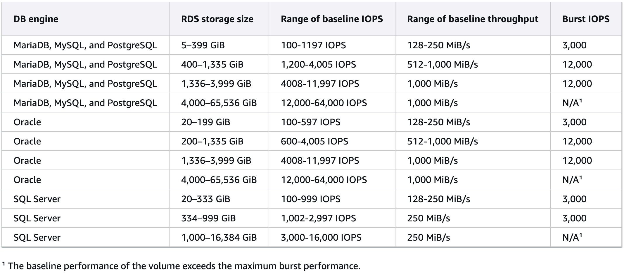
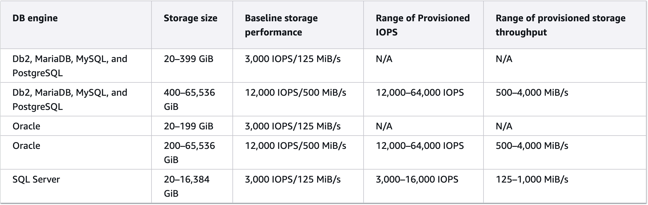
At the time of publishing, Outposts racks support the RDS for SQL Server, RDS for MySQL, RDS for Oracle, and RDS for PostgreSQL database engines. Database instance performance varies depending on the EC2 instance type selected for the database, the EBS volume type selected for RDS database storage, the database engine selected, and the size of the RDS database storage. The following tables show expected IOPS for database instances using gp2 and gp3 EBS volume types respectively, as shown in the General Purpose SSD Storage section of the Amazon RDS user guide.

Figure 2 - Expected IOPS for gp2 volume type used for Amazon RDS storage. Note: RDS MariaDB is not supported on Outposts.

Figure 3 - Expected IOPS for gp3 volume type used for Amazon RDS storage. Note: RDS MariaDB and RDS for Db2 DB engines are not supported on Outposts.

To calculate your database instance performance, consider all influencing factors. For example, if you wanted to support the maximum IOPS of 16,000 shown for the SQL Server RDS database engine, you would need:

  • 32 GiB gp3 volume, OR
  • 5,334 GiB gp2 volume.
  • At least an r5.4xlarge, which can provide a baseline 18,750 IOPS. If using a second-generation Outposts rack, r7i.4xlarge and r8i.4xlarge instances provide a baseline of 20,000 IOPS. However, they are constrained by the lowest performing subsystem, which would be the amount of I/O the database engine can support (16,000 for SQL Server).

The storage type and size have the biggest impact on IOPS performance. For high I/O databases, we recommend either purchasing additional gp2 storage for your first-generation Outpost rack (understanding you might need to provision more storage than needed to meet your IOPS requirements), or using second-generation Outposts racks which support the more performant gp3 EBS storage type for your database workloads. Also consider that Outposts racks have a fixed storage capacity, and aggregate workload IOPS should be reviewed.

Monitoring IOPS

To check that the infrastructure is sized correctly to meet your IOPS expectations, use Amazon CloudWatch EBS volume metrics. You can monitor your EBS volume performance and set CloudWatch Alarms if the values exceed, for example, 70% of the total. Metrics such as VolumeReadBytes and VolumeWriteBytes provide information on the read and write operations in a specified time period based on bytes, and likewise VolumeReadOps and VolumeWriteOps provide the same information based on completed operations. You can monitor the time taken for read and write operations for an Amazon EBS volume using the VolumeTotalReadTime and VolumeTotalWriteTime metrics respectively using the Average statistic. Use IAM policies to restrict who can view, create, or modify CloudWatch alarms and dashboards for your Outpost resources. This prevents unauthorized users from suppressing critical storage performance alerts.

You can also use the Latency Injection action in AWS Fault Injection Service to run controlled experiments to test your architecture and monitoring based on this metric to improve your resiliency to storage performance degradation. You can access real-time detailed performance statistics for Amazon EBS volumes that are attached to Nitro-based Amazon EC2 instances. You can combine these statistics to derive average latency and IOPS, or to check whether I/O operations are completing. You can also view the total amount of time that your application has exceeded your EBS volume’s or the attached instance’s provisioned IOPS or throughput limits. By tracking increases in these statistics over time, you can identify whether you need to increase your provisioned IOPS or throughput limits to optimize your application’s performance. The detailed performance statistics also include histograms for read and write I/O operations, which provide a distribution of your I/O latency by keeping track of the total number of I/O operations completed within a latency band. See Monitor your Outposts rack and Monitoring best practices for AWS Outposts for general Outposts monitoring guidance.

When running FIS experiments, follow the principle of least privilege by scoping IAM roles to specific resources, and always configure stop conditions to automatically halt experiments that exceed expected impact thresholds.

Conclusion

This post explains how to size EC2 instances and EBS storage on Outposts racks to meet your IOPS and throughput requirements, helping you avoid performance bottlenecks for database and application workloads. You can monitor EBS storage performance through CloudWatch and create alarms to alert you when your instance approaches its IOPS threshold. To learn more about Outposts and how to architect for IOPS and throughput performance for your workloads, reach out to your AWS account team, or visit the AWS Outposts contact page.

Enabling high availability of Amazon EC2 instances on AWS Outposts servers (Part 3)

Post Syndicated from Brianna Rosentrater original https://aws.amazon.com/blogs/compute/enabling-high-availability-of-amazon-ec2-instances-on-aws-outposts-servers-part-3/

This post is part 3 of the three-part series ‘Enabling high availability of Amazon EC2 instances on AWS Outposts servers’. We provide you with code samples and considerations for implementing custom logic to automate Amazon Elastic Compute Cloud (EC2) relaunch on Outposts servers. This post focuses on guidance for using Outposts servers with third party storage for boot and data volumes, whereas part 1 and part 2 focus on automating EC2 relaunch between standalone servers. Outposts servers support integration with Dell PowerStoreHPE Alletra Storage MP B10000 systems, NetApp on-premises enterprise storage arrays, and Pure Storage FlashArray.

Outposts servers provide compute and networking services that are designed for low-latency, local data processing needs for on-premises locations such as retail stores, branch offices, healthcare provider locations, or environments that are space-constrained. Outposts servers use EC2 instance store storage to provide non-durable block-level storage to the instances running stateless workloads. For applications that require persistent storage, you can create a three-tier architecture by connecting your Outposts servers to a third-party storage appliance. In this post, you will learn how to implement custom logic to provide high availability (HA) for your applications running on Outposts servers using two or more servers for N+1 fault tolerance. The code provided is meant to help you get started, and can be modified further for your unique workload needs.

Overview

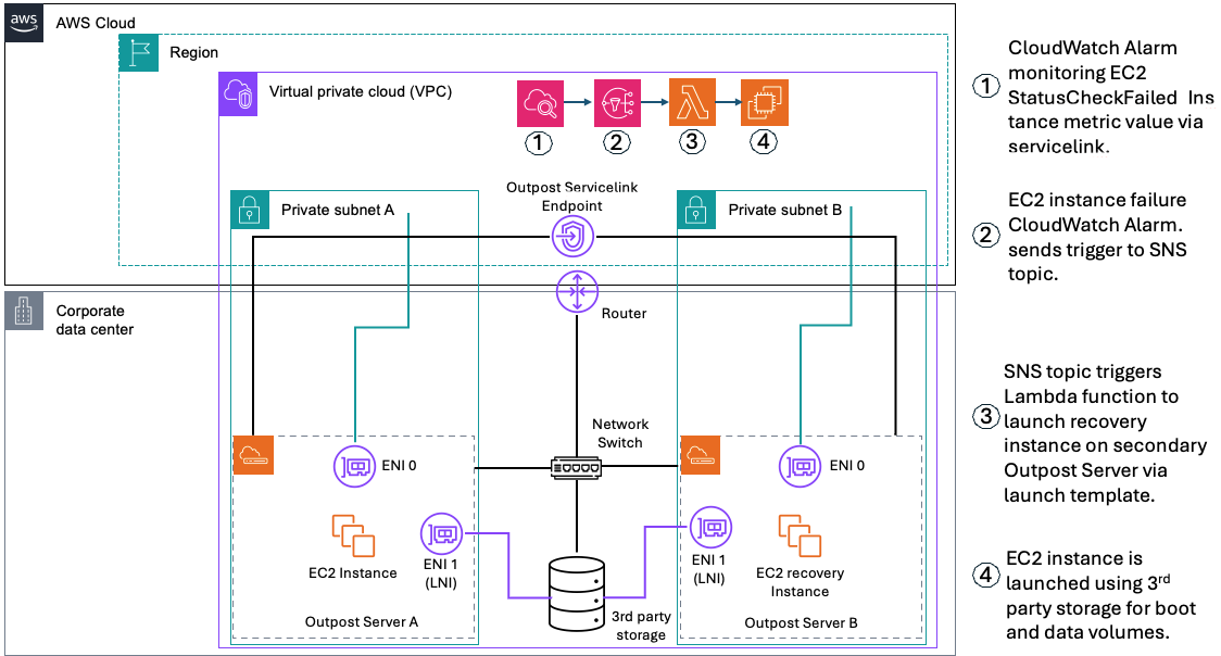
In the following sections we will show how custom logic can be used to automate EC2 instance relaunch between two or more Outposts servers using boot and data volumes on third party storage. If your EC2 instance fails while using this solution, an Amazon CloudWatch alarm monitoring the EC2 StatusCheckFailed_Instance metric of your source EC2 instance will be triggered, and you will receive an Amazon Simple Notification Service (Amazon SNS) notification. An AWS Lambda function will then relaunch your EC2 instance onto the destination Outposts server that you’ve set up for resiliency. This is done using a launch template created during setup, and the script will connect your relaunched instance to the existing boot and data volumes on your third party storage appliance. This storage device provides shared storage for your Outposts servers. If a single server fails, new instances can connect to existing volumes on the array. This allows for a zero data loss Recovery Point Objective (RPO) and a Recovery Time Objective (RTO) equaling the time it takes to launch your EC2 instance. Take advantage of the features on your storage appliance for configuring data durability and resiliency to hardware failures, and make sure that you are regularly backing up your SAN volumes.

Figure 1 – Solution Architecture for automated EC2 Relaunch

Prerequisites

The following prerequisites are required to complete the walkthrough:

  • Two Outposts servers that can be set up as an active-active or active-passive resilient pair.
  • For workloads with a low threshold for downtime, ensure that your secondary Outpost server that’s used for recovery has a unique service link connection.
  • Outposts servers must be colocated within the same Layer 2 (L2) network.
  • Network latency between the Outposts servers must not exceed 5ms round trip time (RTT).
  • A storage appliance that supports the iSCSI protocol. Credentials to manage the storage appliance initiator/target mappings. See Simplifying the use of third-party block storage with AWS Outposts for more information.
  • If you’re setting this up from an Outposts consumer account, you must configure Amazon CloudWatch cross-account observability between the consumer account and the Outposts owning account to view Outposts metrics in your consumer account.
  • Create launch templates for the EC2 instances that you want to protect, the launch wizard will help you create these.
  • Credentials with permissions for AWS CloudFormation, Amazon EC2, and (optional) AWS Secrets Manager if authentication is required. IAM Permission Examples.md is provided in the repository.
  • A Windows or Linux host that can access the storage appliance and your AWS account (management computer).
  • AWS Outposts iPXE Amazon Machine Image (AMI) from the AWS Marketplace.
  • Python 3.8 or later (recommended) is used to run the init.py script that dynamically creates a CloudFormation stack in the account specified as an input parameter.
  • AWS SDK for Python (Boto3) version 1.26.0 or later recommended.
  • Operating system with iSCSI boot support (Windows Server 2022 and Red Hat Enterprise Linux 9 AMIs are provided).
  • Internet access to AWS service endpoints for the private subnet hosting the recovery Lambda function.
  • Download the repository sample-outposts-third-party-storage-integration.

Walkthrough

The first step is to deploy an EC2 instance configured to boot from a volume on the third-party storage that is prepared with an OS boot image. This step uses the launch wizard portion of the solution.

  1. Download and extract the OutpostServer_Recovery_3Pstorage repository to the management computer that has the AWS SDK for Python (Boto3) and Python installed.
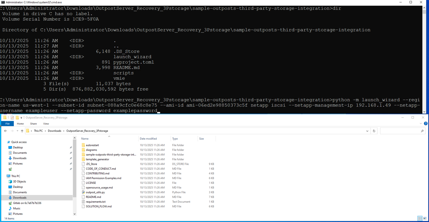
  2. Run launch_wizard from the sample-outposts-third-party-storage-integration directory. You can run interactively or provide arguments for region, subnet, iPXE AMI, storage vendor, storage management ip, and credentials.

Figure 2 – Running launch wizard

  1. When prompted for a feature name, enter sanboot.
  2. For Guest OS type, enter in Linux or Windows.
  3. When prompted “Do you want to continue with this unverified AMI?”, select Y.
  4. The launch wizard will provide a list of instance types available on the Outpost server associated with the subnet you specified. Enter the instance type that you want to use.
  5. The launch wizard will now prompt you for optional EC2 Key Pair, Security Group, and Instance Profile settings for the EC2 instance that you are launching.
  6. Next, the launch wizard prompts you to specify an instance name. Note that specifying an instance name is required to set up automated instance recovery because the instance name is used as part of the recovery process.

Figure 3 – Taking user input for variable values

  1. The launch wizard prompts for root volume size. This is the root volume that the iPXE AMI boots from. The default is a 1GB volume on the Outpost server instance storage.
  2. Next, the launch wizard prompts you to select which third party storage controller you want to use based on the management ip that you specified. In this example, we are using NetApp, so I select a NetApp Storage Virtual Machine (SVM) named outpost_iscsi.
  3. If the connection to the storage array is successful and the protocol is available (iSCSI or NVMe over TCP) you are provided additional storage options for initiator group and logical unit number (LUN).
  4. In this example, we are using NetApp with iSCSI, so I can select an existing initiator group or create a new one.
  5. You can specify an existing initiator qualified name (IQN), or the launch wizard can generate a new one. IMPORTANT: Make sure that IQNs are unique to each instance because duplicates can cause data corruption.
  6. Next the launch wizard prompts which LUN’s you want to connect to this instance. For this example, I am going to use a Windows Server 2022 boot volume that I already created on the NetApp storage array.
  7. You are now asked which storage array target interface you want to use for connecting to these LUNs.
  8. The launch wizard provides the capability to specify guest OS scripts to customize the OS after sanboot. Combining this capability with storage array cloning provides a streamlined process for deploying new instances.
  9. The launch wizard now displays the EC2 user data template that it generated for use with the iPXE AMI and asks if you want to proceed with launching the instance.
  10. After the EC2 instance is launched, select yes to proceed with automated instance recovery setup.

Figure 4 – Running launch template creation script

Generating EC2 launch templates for recovery and failback

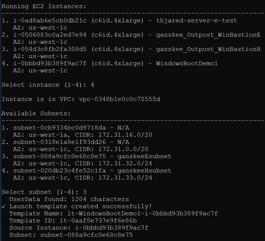
In the second step, we are generating EC2 launch templates for the EC2 instance launched in step 1. Launch templates can be generated for the primary and secondary Outpost servers. The launch template for the secondary Outpost server can be used for automated or manual recovery of the EC2 instance. Failback to the primary Outpost server is manual using the primary launch template.

  1. Select the instance that you want automated recovery for and select the subnet that you launched the instance in. This subnet represents the primary Outpost server that the instance is running on.

Figure 5 – Selecting subnets for EC2 instance relaunch

  1. When prompted to create a second launch template for Outpost server recovery, select yes, and then select to use the same instance (for recovery on different Outpost server).
  2. When you get a list of available subnets, select the subnet that’s associated with your secondary Outpost server. This is the server that the EC2 instance will be launched on in the event of the EC2 StatusCheckFailed_Instance metric triggers the CloudWatch alarm.
  3. You will see both launch templates created successfully.

Deploying automated EC2 instance recovery

The third step creates a CloudFormation template for monitoring, notifications, and automated recovery of the EC2 instance deployed in step 1. The CloudFormation template automatically captures the instance and secondary launch template information necessary for automatic recovery.

  1. Select Y to set up automated recovery. This will create a CloudFormation stack.
  2. Provide a name and description for the CloudFormation stack.
  3. Select whether you want automated recovery or notification only. This provides flexibility to choose manual or automatic recovery based on whether you want to verify the primary Outpost server is down before initiating recovery.
  4. In the AWS CloudFormation console, monitor the CloudFormation stack creation process.

Figure 6 – CloudFormation stack creation in progress

  1. After the CloudFormation Stack is complete, you have successfully deployed an EC2 instance using third party storage for boot and data volumes on a primary Outpost server. You also created instance recovery capabilities by using the Amazon Outpost server automated recovery solution for third party storage.
  2. You can verify whether the EC2 StatusCheckFailed_Instance is healthy under the Alarms section in the Amazon CloudWatch console.

Considerations

The logic discussed in this post relies on the secondary destination Outposts server having a connected service link. For more information about how to create a highly available service link connection for your Outpost servers, see the Networking section of AWS Outposts High Availability Design and Architecture Considerations whitepaper.

Clean up

Confirm whether it is safe to terminate the Amazon EC2 instance that you launched with this walkthrough. The operating system and data volumes are on the third party storage, so EC2 instance termination only removes the iPXE AMI from the Outposts server instance storage. To clean up, complete the following steps.

  1. Terminate the Amazon EC2 instance. Then, verify that the Instance state is Terminated to ensure that the instance is not using Outposts server resources.
  2. Delete the Amazon EC2 Launch Templates associated with the Amazon EC2 instance that you terminated. The names of the launch templates that were automatically generated will start with ‘lt-‘, followed by the instance name and the instance id. If you generated a recovery launch template, it will have a ‘-recovery’ suffix in the name.
  3. Delete the AWS CloudFormation Stack. The Stack name will start with ‘autorestart-‘ followed by the Amazon EC2 instance name.
  4. Clean up your initiators, initiator group, and LUNs on the third party storage array.

Conclusion

With the use of custom logic through AWS tools such as CloudFormation, CloudWatch, Amazon SNS, and AWS Lambda, you can architect for HA for stateful workloads on Outposts server. By implementing the custom logic in this post, you can automatically relaunch EC2 instances running on a source Outposts server to a secondary destination Outposts server if an instance fails, and connect to existing volumes on a shared storage appliance for recovery. This also reduces the downtime of your applications in the event of a hardware or service link failure. The code provided in this post can be further expanded upon to meet the unique needs of your workload.

While the use of infrastructure-as-code (IaC) can improve your application’s availability and be used to standardize deployments across multiple Outposts servers, it’s crucial to do regular failure drills to test the custom logic in place. This is to make sure that you understand your application’s expected behavior on relaunch in the event of a failure. To learn more about Outposts servers, visit the Outposts servers User Guide. Reach out to your AWS account team, or fill out this form to learn more about Outposts servers.

Simplify network segmentation for AWS Outposts racks with multiple local gateway routing domains

Post Syndicated from Brianna Rosentrater original https://aws.amazon.com/blogs/compute/simplify-network-segmentation-for-aws-outposts-racks-with-multiple-local-gateway-routing-domains/

AWS now supports multiple local gateway (LGW) routing domains on AWS Outposts racks to simplify network segmentation. Network segmentation is the practice of splitting a computer network into isolated subnetworks, or network segments. This reduces the attack surface so that if a host on one network segment is compromised, the hosts on the other network segments are not affected. Many customers in regulated industries such as manufacturing, health care and life sciences, banking, and others implement network segmentation as part of their on-premises network security standards to reduce the impact of a breach and help address compliance requirements. Some AWS services also have network requirements that specify certain IP ranges to be used for endpoints, and may or may not support customers bringing their own IP pool (also called CoIP routing, see How to choose between CoIP and Direct VPC routing (DVR) modes on AWS Outposts rack for more information). Customers want the flexibility to use both routing modes (CoIP and DVR) on the same logical Outpost. With this new feature, AWS Outposts racks now support multiple LGW routing domains to meet subnetwork isolation and cloud service network requirements in an on-premises environment. For example, a leading automotive company deploys latency-sensitive manufacturing workloads on Outposts racks in a multi-AZ architecture for resiliency. This feature provides traffic separation between routing domains and enables both customer-owned IP (CoIP) and direct VPC routing (DVR) modes on the same logical Outpost.

In this post you will learn how to use multiple LGW routing domains on Outposts racks and considerations for implementation.

Overview

With the introduction of multiple LGW routing domains on Outposts, you can now create multiple routing domains and associate one or more VLANs with each routing domain. This allows you to integrate your Outposts rack into your existing on-premises network schema. Each LGW routing domain will have a unique LGW Virtual Interface (VIF) Group and an LGW Route Table, enabling logical network traffic isolation. You can have a mix of up to 10 active routing domains with route tables using either DVR or CoIP routing mode, and you can make changes to these routing domains as needed in a self-service fashion allowing for network flexibility as architectures are updated over time. These settings can be found in the AWS Outposts console under the Networking tab in the menu.

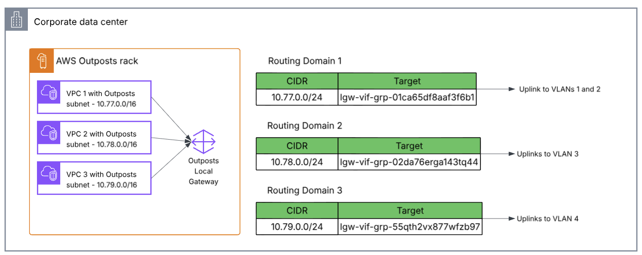
The following diagram shows an example of 3 VPCs, each with at least 1 subnet on the Outpost rack, and each VPC corresponds to its own routing domain. Each routing domain can then be associated with one or more VLANs, and one or more VPCs. A VPC can be associated with one or more LGW routing domain.

Architecture diagram showing 3 routing domains uplinking to an on-premises network.

Figure 1 – Architecture diagram showing 3 routing domains

Walkthrough

Before creating a LGW routing domain, first you’ll need to create an LGW VIF group and an LGW route table. A local gateway routing domain is the association of a local gateway route table and local gateway VIF group. Each VIF group can be associated with one or more VLANs, but a route table can only be associated with one VIF group.

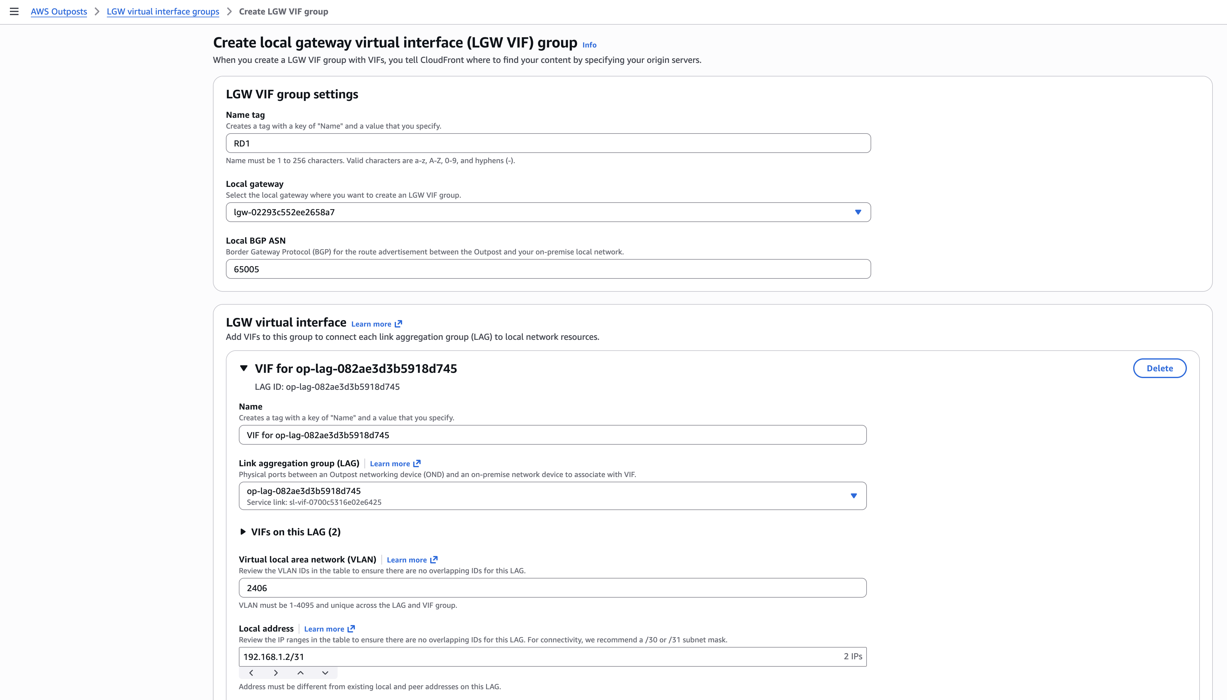
To create a LGW VIF Group, navigate to the AWS Outposts console, go to LGW virtual interfaces groups, and select Create VIF group. Enter your VIF details which include BGP and VLAN routing information, you must create 4 LGW VIFs per VIF group.

Creating VIF group for RD1 routing domain

Figure 2 – Creating VIF group for RD1 routing domain

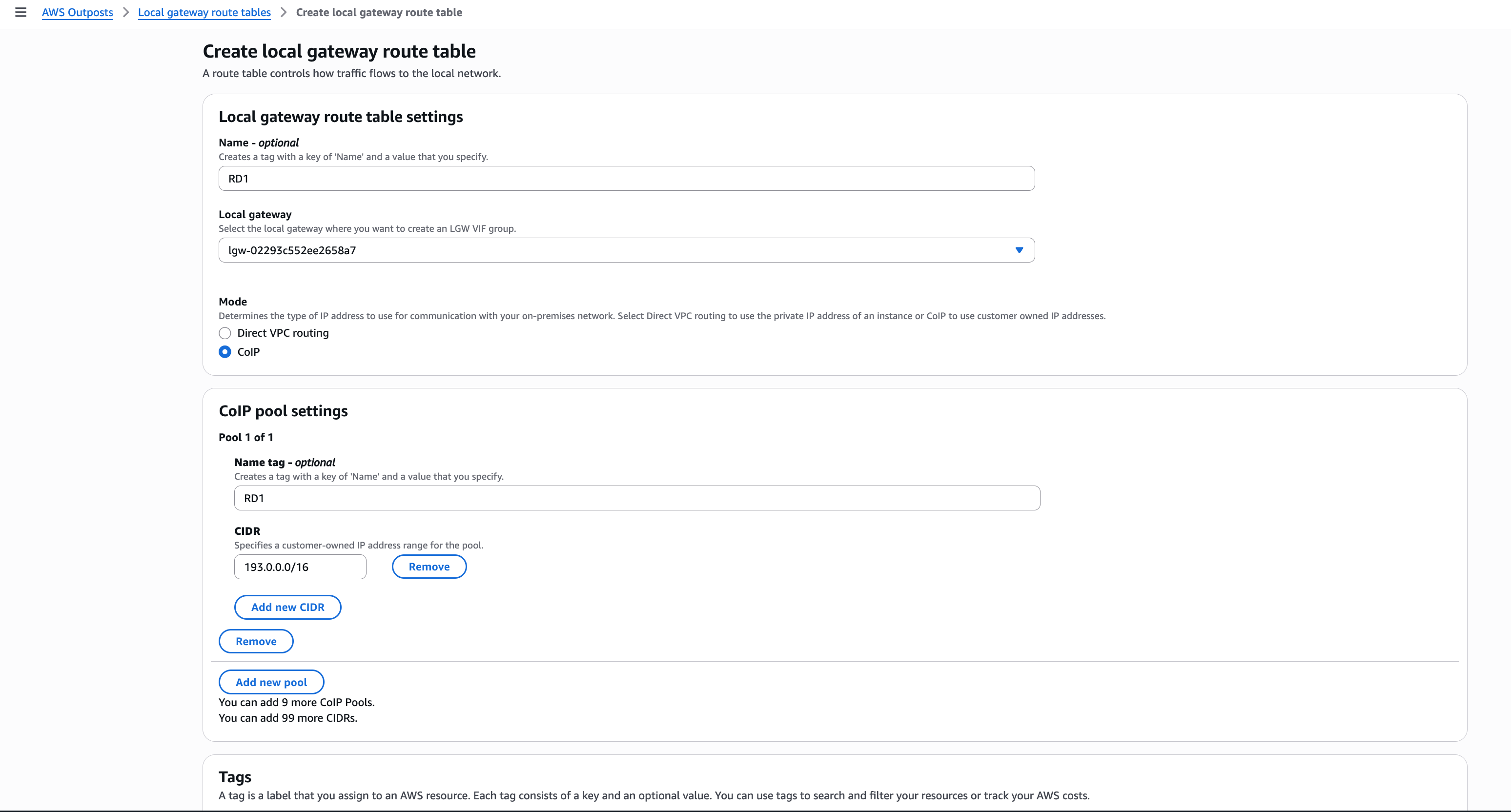
After creating your VIF group, create a LGW route table. You’ll have the option to use Direct VPC Routing (DVR) or Customer-owned IP address pool (CoIP) routing. If CoIP routing is selected, you’ll have the option to enter your CIDR before creating. A LGW route table’s routing mode cannot be changed after creating. However, you can disassociate a LGW route table from a VIF group and attach a new route table if you need to change the routing mode of a VIF group.

Figure 3 – Creating LGW route table for RD1 routing domain

After you’ve created your LGW route table and VIF group, you can proceed to the final step which is to create your LGW routing domain where you will associate the LGW route table and VIF group.

Create LGW routing domain form for RD1 example

Figure 4 – Creating LGW routing domain for RD1

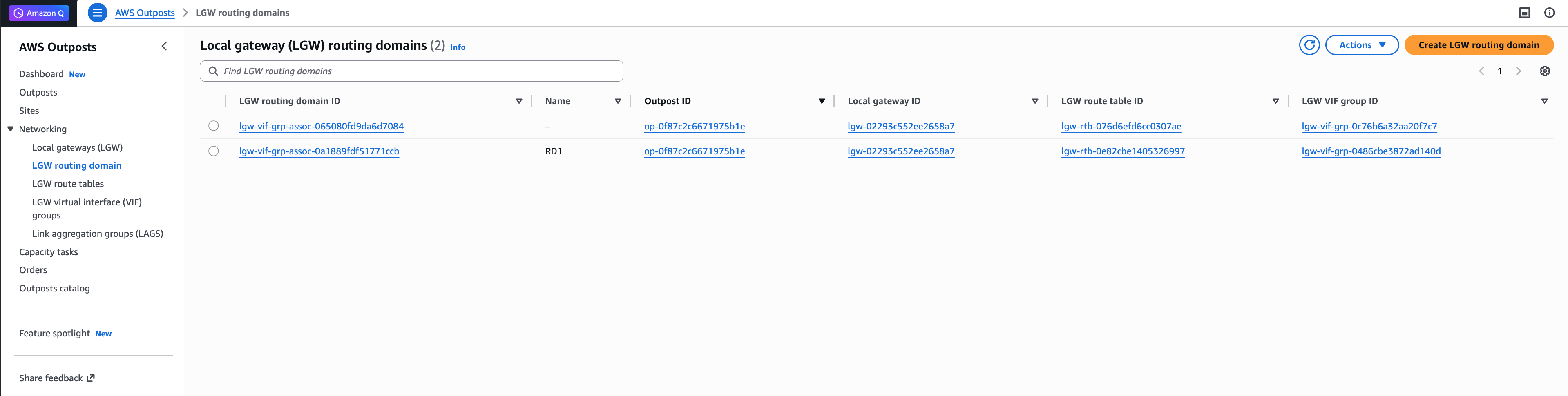
You can view and create up to 10 active routing domains through the AWS Outposts console under the Networking tab.

Figure 5 – Local Gateway (LGW) routing domains

Considerations

  • Multiple LGW routing domains feature is only available on second-generation Outposts racks.
  • Avoid overlapping IP addresses across subnetworks and local routing domains as those can create IP routing conflicts.
  • A VIF group can only be associated to one LGW route table/routing domain at a time. A routing domain is the association of a VIF group and LGW route table.
  • LGW routing domain will allow for logical local network traffic isolation, however all traffic will still travel across your local gateway Link Aggregation Control Protocol (LACP) Link Aggregation Group (LAG) to uplink into your on-premises network.
  • Additional network isolation can be achieved through Virtual Routing and Forwarding (VRF) on Cisco platforms or Routing Instances on Juniper equipment, providing logical separation of routing tables and enabling secure multi-tenancy within the same physical infrastructure.
  • You can associate a VPC to one or more LGW routing domains. You can self-serve to change VPC association as needed. Multiple on-premises VLANs can be connected to a single routing domain.

Conclusion

This post demonstrated how to configure multiple local routing domains on Outposts racks to integrate into your on-premises network. For more information see LGW routing domains section in the AWS Outposts user guide. Reach out to your AWS account team to learn more about Outposts racks network configuration options.

In addition to multiple LGW routing domains, we have also announced several updates to Outposts in the past week to help you meet digital sovereignty and local data processing needs. To learn more, read the following announcements:

To discuss Outposts with an expert on any of these topics, submit this form.

Multi-rack and multiple logical AWS Outposts architecture considerations for resiliency

Post Syndicated from Brianna Rosentrater original https://aws.amazon.com/blogs/compute/multi-rack-and-multiple-logical-aws-outposts-architecture-considerations-for-resiliency/

AWS Outposts rack offers the same Amazon Web Services (AWS) infrastructure, AWS services, APIs, and tools to virtually any on-premises data center or colocation space for a truly consistent hybrid experience. A logical Outpost (hereafter referred to as an Outpost) is a deployment of one or more physically connected Outposts racks managed as a single entity under one Amazon Resource Name (ARN). An Outpost provides a pool of AWS compute and storage capacity at one of your sites as a private extension of an Availability Zone (AZ) in an AWS Region. Several AWS services that support Outposts offer deployment options that improve your workload’s fault tolerance. However, certain Outposts configuration requirements have to be met in order to use them.

In this post, we explore the architecture considerations that come into play when deciding between a multi-rack logical Outposts rack, or using multiple Outposts racks to support your highly available workloads.

Amazon EC2 on AWS Outposts rack

The following sections cover Amazon Elastic Compute Cloud (Amazon EC2) on Outposts rack

Multi-rack logical Outposts

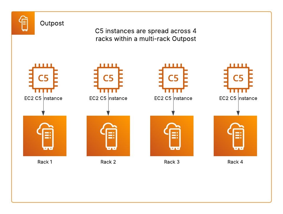
When using a multi-rack logical Outpost, you can use a rack level spread Amazon EC2 placement group. A rack level spread placement group can have as many partitions as you have racks in your Outpost deployment, and this allows you to spread out your instances to improve the fault tolerance of your workloads. In the following example, we have C5 instances in an Amazon EC2 Auto Scaling group that uses a launch template specifying a rack level spread placement group strategy should be used. This multi-rack Outpost has four racks, thus the instances are spread across the four racks as evenly as possible.

Rack level spread EC2 placement group example

Figure 1: Rack level spread Amazon EC2 placement group example

This placement group strategy can make your workloads more resilient to rack or host failures, but it would not be useful in mitigating an AZ failure. EC2 instances on Outposts are statically stable to network disconnects. Therefore, workloads would continue running during an AZ failure, but mutating actions would be unavailable. Read on to see how this strategy can be used with multiple Outposts to create a multi-AZ resilient architecture.

Multiple Outposts racks

If you have more than one logical Outpost in the same Region, we recommend connecting each Outpost to a different AZ. This would allow you to create multi-AZ resilient architectures, and when used in combination with features such as Intra-VPC communication between your Outposts, you can stretch an Amazon EC2 Auto Scaling group across two or more Outposts in the same VPC. If each Outpost is a single rack deployment, then this can be combined with a host level spread placement group specified in your instance launch template. A host level spread placement group can have as many partitions as you have hosts of that instance type in your Outpost, and would improve your workload’s resiliency to host failures.

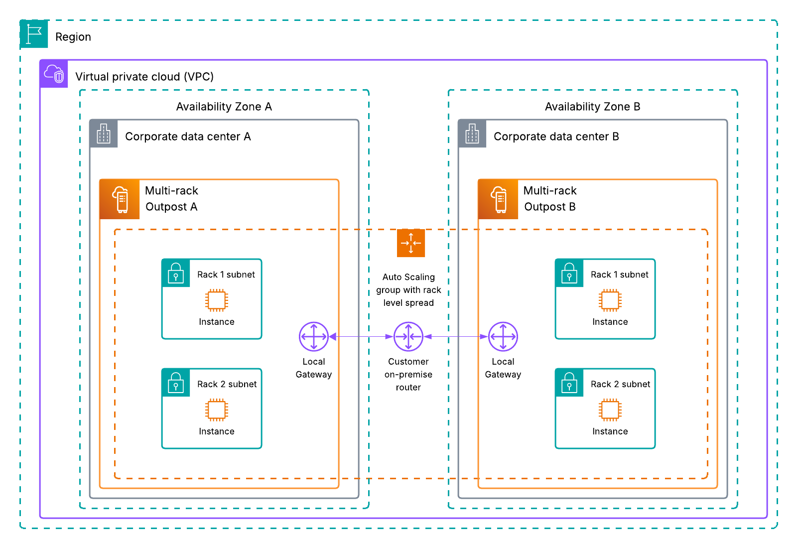
For the highest level of spread and resiliency, consider using multiple multi-rack logical Outposts. This would allow you to use rack level spread placement groups, and intra-VPC communication between Outposts, as shown in the following figure. Having more than one multi-rack Outpost allows you to create application architectures that are resilient toward hardware and AZ level failures by spreading your workload across as many fault domains as possible.

Intra-VPC communication between two multi-rack logical Outposts using an EC2 auto scaling group with rack level spread

Figure 2: Intra-VPC communication between two multi-rack logical Outposts using an Amazon EC2 Auto Scaling group with rack level spread

Amazon RDS on AWS Outposts rack

The following sections cover Amazon Relational Database Service (Amazon RDS) on Outposts rack.

Multi-rack logical Outposts

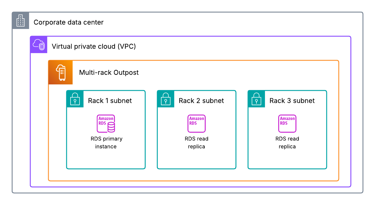
Amazon RDS on Outposts rack supports read replicas, which use the MySQL and PostgreSQL database engines’ built-in asynchronous replication functionality to create a read replica from a source database instance. Read replicas on Amazon RDS on Outposts can be located on the same Outpost or another Outpost in the same VPC as the source database instance, as shown in the following figure. Furthermore, these can be used to scale out beyond the capacity constraints of a single database instance for read-heavy database workloads. They can also be used to maintain a second copy of your database, which can be used in the event of a host failure to improve workload resiliency. The process to promote a read replica to primary must be manually initiated, and your DNS records must be updated to the new primary instance. However, this is a good option to improve database durability if you only have one logical Outpost. Multiple read replicas can be created for a single database instance for added resiliency. You can also create an Amazon RDS read replica for a single rack Outpost to improve your resiliency to host failures. However, having a multi-rack Outpost would allow you to spread your read replica to another rack within your Outpost.

RDS read replicas used with a multi-rack Outpost

Figure 3: Amazon RDS read replicas used with a multi-rack Outpost

Multiple Outposts racks

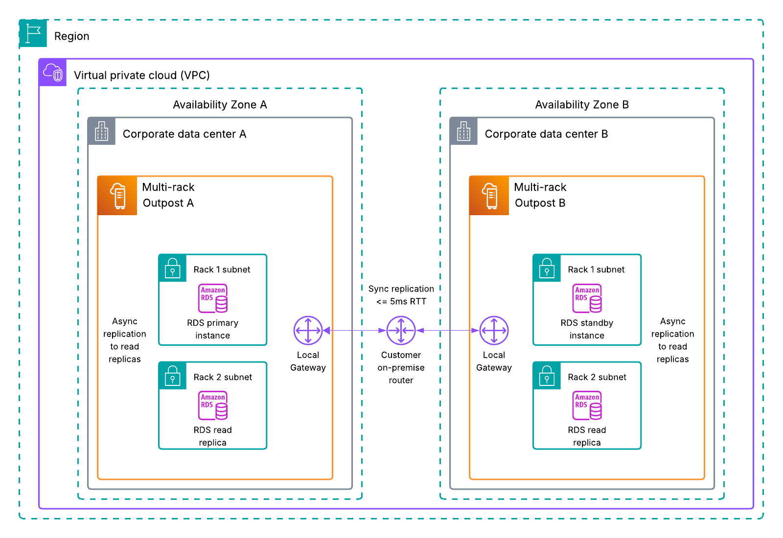
Multi-AZ Amazon RDS deployments are supported on Outposts rack for MySQL and PostgreSQL database instances, as shown in the following figure. Using your Outposts Local Gateway and synchronous data replication, Amazon RDS creates a primary database instance on one Outpost, and maintains a standby database instance on a different Outpost. Failover to a multi-AZ Amazon RDS standby instance is automatic, and the DNS records are also automatically updated as part of the failover process. Using this deployment option protects you from AZ, host, and Outpost failures. You can also use multi-AZ Amazon RDS in combination with read replicas spread across different hosts on the same rack, or across multiple racks if using two multi-rack Outposts to provide more database durability.

Multi-AZ RDS on Outposts using read replicas for added durability.

Figure 4: Multi-AZ Amazon RDS on Outposts using read replicas for added durability

Amazon EKS on Outposts rack

The following sections cover Amazon Elastic Kubernetes Service (Amazon EKS) on Outposts rack.

Multi-rack logical Outposts

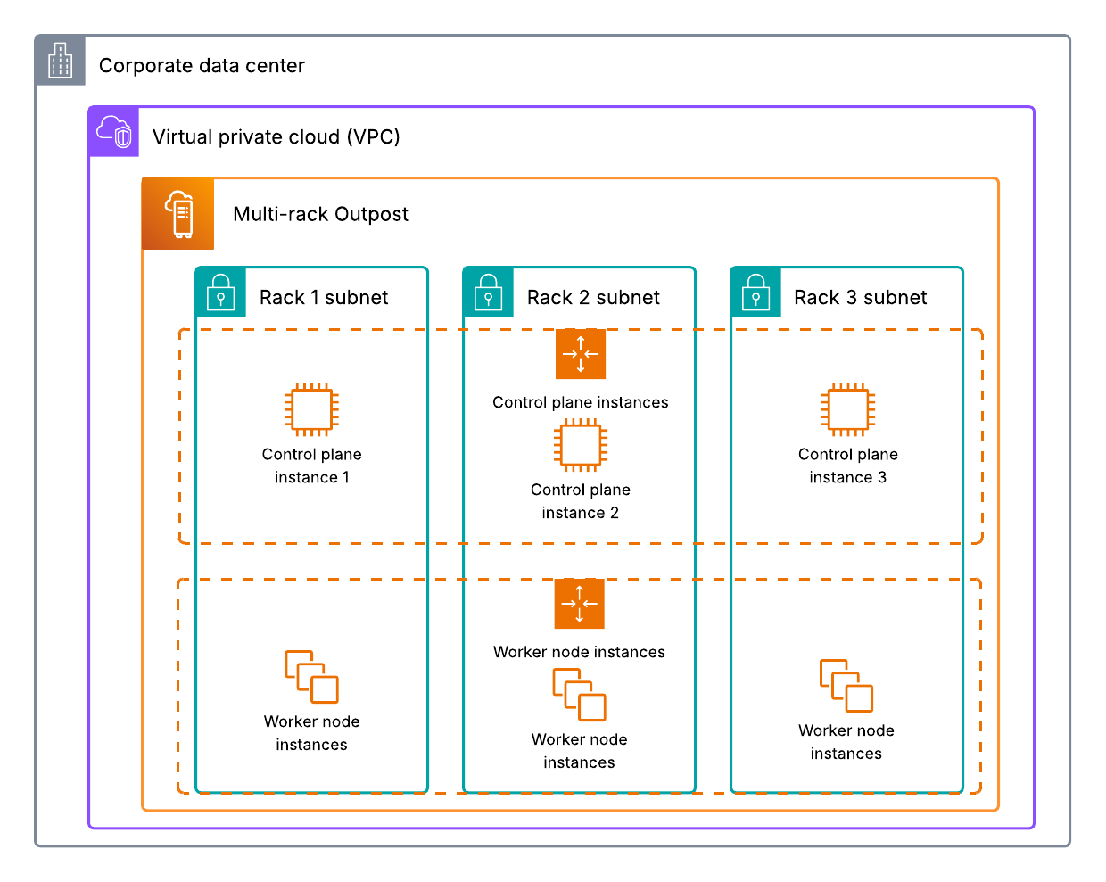
Outposts rack supports two Amazon EKS deployment methods: EKS extended cluster, and EKS local cluster, as shown in the following figure. Go to our documentation for help deciding which method is right for your workload. Using the rack level placement group strategy discussed earlier in this post allows you to spread your EKS instances (worker and control plane depending on the deployment model used) across multiple racks within your Outpost. Amazon EKS control plane instances are automatically replaced in the event of an instance, host, or rack failure, and self-managed worker node instances are typically placed in an Amazon EC2 Auto Scaling group. Therefore, when they’re used with a rack level spread placement group, you can increase your Amazon EKS resiliency and use automation to handle failures.

EKS local cluster with rack level spread placement group and auto scaling

Figure 5: EKS local cluster with rack level spread placement group and auto scaling

Multiple Outposts racks

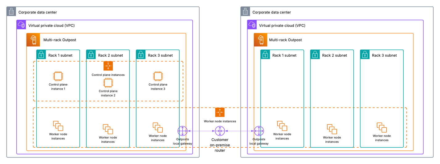
When using multiple Outposts racks, you’re unable to spread EKS control plane instances across two disparate Outposts. Go to Deploy an Amazon EKS cluster across AWS Outposts with Intra-VPC communication for more information on how to stretch an EKS extended cluster across multiple Outposts racks. If EKS local cluster is a requirement for your workload, you could use an external load balancer and deploy one instance of EKS local cluster on each Outpost in an active/active or active/passive configuration, and use the load balancer to direct incoming traffic to each respective EKS cluster. If your EKS cluster is using persistent storage, then you should consider whether each cluster needs access to the other clusters data, and centralized storage or replication should be used if needed.

Alternatively, if you are using EKS local cluster with two single rack Outposts, then you can also choose to only spread your EKS worker node instances across both of your Outposts. Furthermore, you can use host level spread on your primary Outpost to provide host level resiliency for your control plane instances. This would provide some added durability in the event of a host failure, and you could withstand the failure of your secondary Outpost that is only running some of your worker node instances. If you have two multi-rack Outposts, even though you couldn’t spread your control plane instances across Outposts, you can still use a rack level spread placement group to spread them across racks within your primary multi-rack Outpost. This would provide resiliency against instance, host, rack, and AZ level failures, and you could withstand the failure of your secondary multi-rack Outpost that isn’t running your EKS control plane instances as well.

EKS local cluster using two multi-rack Outposts and rack level spread

Figure 6: EKS local cluster using two multi-rack Outposts and rack level spread

Amazon S3 on Outposts rack

The following sections cover Amazon S3 on Outposts rack.

Multi-rack logical Outposts

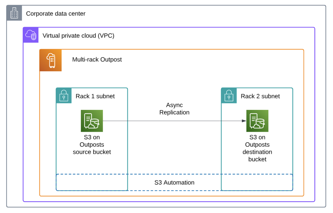
Amazon S3 on Outposts supports object replication, either across distinct Outposts, or between buckets on the same Outpost to help meet data-residency needs. The Outpost or bucket you’re replicating to can be in the same AWS account, or a different account. If you have a multi-rack Outpost, then you can replicate your S3 objects to another bucket on the same Outpost to create a copy of your data locally for added resiliency.

S3 replication between buckets on the same Outpost

Figure 7: Amazon S3 replication between buckets on the same Outpost

Multiple Outposts racks

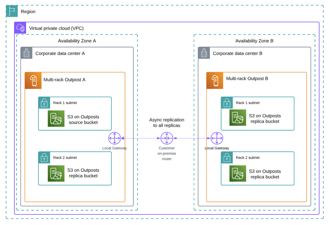
Moreover, if you have multiple Outposts, then you can replicate S3 objects between buckets on each Outpost, as shown in the following figure. Connect each Outpost to a unique AZ to create a multi-AZ resilient architecture, and store a copy of your data on each Outpost. You can combine this with Amazon S3 replication to a bucket on the same Outpost as well, and have multiple replicas managed through Amazon S3 automation for the highest availability. AWS DataSync also supports Amazon S3 on Outposts, and can be used to replicate S3 objects to the Region your Outpost is connected to if you want to store a copy of your data in the cloud, or use Amazon S3 in the Region for data tiering. Refer to Automate data synchronization between AWS Outposts racks and Amazon S3 with AWS DataSync for more information.

S3 replication across two multi-rack Outposts

Figure 8: Amazon S3 replication across two multi-rack Outposts

Further considerations

  • When using multiple Outposts, we recommend connecting each Outpost to a unique availability zone to use multi-AZ deployment options.
  • Outposts are designed to be a connected service, and network outages could cause workflow disruptions. AWS can help you design for continued operations during network outages. We recommend creating a redundant service link connection to support workloads on Outposts with high availability requirements. Go to AWS Direct Connect Resiliency Recommendations for guidance on how to create a highly available service link connection through AWS Direct Connect, and Satellite Resiliency for AWS Outposts.
  • Outposts have a finite amount of compute resources based on the physical configuration chosen, and the logical capacity configuration on your Outpost can be changed at any time using a capacity task. If the Amazon EC2 compute requirements for your workload change over time, then your Outposts capacity configuration can be updated to meet these requirements non-disruptively. Go to Dynamically reconfigure your AWS Outposts capacity using Capacity Tasks for more information.

Conclusion

This post explores the architecture options and considerations for deciding between a multi-rack Outpost, and using multiple Outposts to support your highly available workloads. For more information on how to design highly available architecture patterns for Outposts, go to the AWS Outposts High Availability Design and Architecture Considerations whitepaper. Reach out to your AWS account team, or fill out this form to learn more about Outposts and self-service capacity management.

Control instance placement using Asset Level Capacity Management for AWS Outposts

Post Syndicated from Brianna Rosentrater original https://aws.amazon.com/blogs/compute/control-instance-placement-using-asset-level-capacity-management-for-aws-outposts/

AWS Outposts supports self-service capacity management at the entire Outpost level, or at the individual asset level, making it easy for you to view and manage compute capacity on your Outposts. This feature supports both Outposts rack (such as the recently announced second-generation Outposts rack) and Outposts server. A default capacity configuration for each new Outpost is determined during the ordering process. This default configuration can subsequently be modified to create a range of Amazon Elastic Compute Cloud (Amazon EC2) instance sizes and quantities to meet your changing business needs. For more information on performing Outposts level multi-asset reconfigurations, go to Dynamically reconfigure your AWS Outposts capacity using Capacity Tasks.

The release of Asset Level Capacity Management allows you to control the configuration of specific assets within your Outpost, which can be useful when planning strategies for EC2 Auto Scaling groups and host-level high availability. An Outpost asset can be a single server within an Outposts rack, or an Outposts server. This post focuses on how to use Asset Level Capacity Management to perform single-host reconfigurations, and how this can be used with Amazon EC2 placement groups to control instance placement on your Outpost.

Overview

When you place an Outposts order, you determine the capacity configuration of each Outpost based on the anticipated workload requirements. You can scale your Outposts up or out as needed during your commitment term. For further details on Outpost capacity planning including best practices, refer to the Capacity Planning – AWS Outposts High Availability Design and Architecture whitepaper. We recommend planning spare capacity for N+M host availability per instance family when making modifications to your Outpost capacity configuration for workloads that need to be highly available. To calculate, take the number of assets (N) you need to run all your workloads, and then add (M) additional assets to meet your requirements for server availability during failure and maintenance events.

You also need to plan for instance level high availability when deciding to reconfigure particular assets. For example, say you have two C5 assets, and each one is configured homogeneously to provide C5.2xlarge instances. If you have an Auto Scaling group that specifies C5.2xlarge in its launch template, and you perform an asset level reconfiguration of one of your C5 assets so that it only offers C5.4xlarge instances, then your Auto Scaling group can only launch instances on the one C5 host configured to provide C5.2xlarge instances. If that host fails, then the Auto Scaling group is unable to launch new C5.2xlarge instances on the other host unless the Auto Scaling group launch template is modified. Understanding failure scenario behavior and how much capacity you want to reserve for high availability is key to capacity management and disaster recovery planning. For highly available workloads, we recommend spreading your instances across as many assets as possible.

Understanding EC2 placement groups on AWS Outposts

Outposts rack supports EC2 placement groups, and two placement group options are available only on Outposts: rack level spread, and host level spread. This allows you to spread out instances across underlying hardware on an Outpost at your site. To use a rack level spread placement group, you must have two or more physical Outpost racks. Each spread strategy can be used to create resilient Outposts architectures that can withstand a rack or host failure depending on the respective strategy used.

Rack level spread

Figure 1: Outposts rack showing a rack level spread EC2 placement group

Figure 1: Outposts rack showing a rack level spread EC2 placement group

Using a multi-rack Outpost, you can spread your EC2 instances across multiple racks with a rack level spread EC2 placement group. When used with Auto Scaling groups, this allows you to withstand an individual rack or multi-asset failure. When your Auto Scaling group detects you’ve lost instances on one of your racks, it automatically relaunches the instances using the assets on your other racks if you have available capacity. To use this strategy to increase your workload resiliency, each rack would need to have assets that can support the instance type (C5 is used in the preceding figure) and size used in your Auto Scaling group launch template. The expanded functionality that asset level capacity management brings to capacity tasks allows you to configure your Outpost so that each rack has at least one asset that can support the instances used in your Auto Scaling groups. Configure your assets on each rack to meet your resiliency goals for host failure tolerance as well. This configuration can be done in an on-demand, self-service fashion to meet the needs of your evolving workloads if instance requirements change over time.

Host level spread

Figure 2: Outposts rack showing a host level spread EC2 placement group

Although rack level spread EC2 placement groups need a multi-rack Outpost, host level spread EC2 placement groups can be used within a single rack Outpost to provide resiliency for your workloads at the asset level. When used with Auto Scaling groups, this allows you to withstand an individual asset or multi-asset failure depending on your Outpost configuration. When your Auto Scaling group detects you’ve lost instances on one of your assets due to a hardware failure, it automatically relaunches the instances using your other assets on your Outpost if you have available capacity. To use this strategy to increase your workload resiliency, you would need to have at least two assets within your Outposts rack that can support the instance type (R5 and M5 are used in the preceding figure) and size used in your Auto Scaling group launch template. Outposts also supports using attribute-based instance type selection if multiple instance types meet your workload needs based on some minimum resource requirements. With the expanded functionality that asset level capacity management brings to capacity tasks, you can configure your Outposts rack so that each asset type can support the instance size used in your Auto Scaling groups. This configuration can be done in an on-demand, self-service fashion to meet the needs of your evolving workloads if instance requirements change over time.

Using asset level capacity tasks

Asset Level Capacity Management allows you to target a specific Outpost asset to change its capacity configuration directly, allowing granular control over instance capacity pool configurations. Outpost assets are referred to by a unique ten-digit Asset ID. The first step in this process is identifying a suitable asset on which to perform the capacity task. To do this, you can use the rack view within the Outposts console page to view each asset, its current capacity configuration, and its current usage. Choosing an asset with fewer running instances may increase the chances of the capacity task being successful without needing instances to be stopped.

In the following example, the rack view has been filtered by the R5 family resulting in the two R5 assets being displayed. The Show instance details option has also been chosen to show the instance IDs of the running instances on our Outposts rack.

Figure 3: Rack view of the Outposts console

When you have identified the asset to target for the capacity task, you can either choose the Modify option in the top right of the asset itself or go to Capacity Tasks from the console menu and choose the asset ID directly from the dropdown menu.

Figure 4: Capacity tasks console experience

From here, you have the option to use the capacity configuration builder to interactively modify your Outposts capacity layout, or you can upload a capacity configuration plan JSON document with the necessary configuration. When building the capacity task, you have two options to choose from when handling instances that are blocking the task from executing. The default option is set to fail the capacity task if this occurs. However, this can be set to wait for the instances to be stopped so that the task can continue. If this option is chosen, then the asset is placed into an isolated state until either the capacity task completes or is cancelled, thus preventing any further instances launches on the impacted asset.

If there are instances on the asset that can’t be stopped to complete the capacity task, then they can be chosen from the Instances to keep as-is section. Only the instances running on the impacted asset are listed. If a capacity task can’t be completed while leaving the chosen instances running, the capacity task fails.

In the following example, the capacity configuration requested for the asset results in the removal of one r5.4xlarge and two r5.2xlarge instances, which creates sufficient space for the creation of 12 r5.large instances. This asset also has three instances running on it which have all been chosen to keep as-is during the execution of the task.

Figure 5: Capacity task example showing r5 asset level capacity management

You can also execute capacity tasks programmatically If you prefer through CLI or API calls. For example, using the start-capacity-task CLI to submit the same configuration would look as follows:

aws outposts start-capacity-task \
--outpost-id op-07f6f537e0607d3f1 \
--asset-id 1702928095\
--instances-to-exclude '{
    "Instances": ["i- 03f53189ffedcc72c", "i-044383b9051299b50", "i-0dfd88574237a68a4"],
    "AccountIds": ["450360193046", "450360193046", "450360193046"],
    "Services": ["EC2", "EC2", "EC2"]
}' \
--task-action-on-blocking-instances FAIL_TASK \
--instance-pools '[
    {
        "InstanceType": "r5.large",
        "Count": 12
    },
    {
        "InstanceType": "r5.xlarge",
        "Count": 6
    },
    {
        "InstanceType": "r5.2xlarge",
        "Count": 4
    },
    {
        "InstanceType": "r5.4xlarge",
        "Count": 1
    }
]'

After defining the capacity task, you are presented with an overview of the requested changes before submitting the task for execution. When it’s submitted, the task first enters a Requested status while the configuration is evaluated, before either being moved to In Progress if the task is valid or Failed if it’s invalid or blocked by running instances.

When the capacity task has successfully completed and the capacity pools for the asset are updated, you can validate this by returning to the rack view within the Outpost console, or by using the CLI/API. The following is an example using the list-assets CLI command:

aws outposts list-assets --outpost-identifier op-07f6f537e0607d3f1 --query "Assets[?AssetId=='1702928095']"

[
    {
        "AssetId": " 1702928095",
        "RackId": "1702928115",
        "AssetType": "COMPUTE",
        "ComputeAttributes": {
            "State": "ACTIVE",
            "InstanceFamilies": [
                "R5"
            ],
            "InstanceTypeCapacities": [
                {
                    "InstanceType": "r5.2xlarge",
                    "Count": 4
                },
                {
                    "InstanceType": "r5.4xlarge",
                    "Count": 1
                },
                {
                    "InstanceType": "r5.xlarge",
                    "Count": 6
                },
                {
                    "InstanceType": "r5.large",
                    "Count": 12
                }
            ],
            "MaxVcpus": 96
        },
        "AssetLocation": {
            "RackElevation": 27.0
        }
    }
]

Only a single capacity task for an asset can be executing at any given time. If you attempt to create a second capacity task for the same asset while the original is still in a Requesting or In Progress status, then the submission of the task fails. However, you can submit multiple capacity tasks for unique assets within the same Outpost. For example, using the CLI commands, you could execute a single script to change the capacity configuration of all assets within an Outpost through individual asset level capacity tasks.

Considerations

  • Make sure that if you’re specifying instance type in your launch templates, then this instance type is available on multiple assets if your workload needs to be resilient against host failures.
  • Understand which failure scenarios could exist within your environment, and plan for how each one should be handled. Failure planning is essential for maintaining workload uptime in production environments.
  • Capacity tasks can only be executed from the AWS account that owns the Outpost. If Outpost resources are shared to workload accounts through AWS Resource Access Manager (AWS RAM), then these accounts can’t submit capacity tasks.
  • You can manipulate your capacity configuration to control instance placement at launch. If only certain assets support the instance size and type you want to deploy, then your instance must be launched on one of those assets.
  • If executing capacity tasks through CLI commands, make sure that your CLI has been updated to the latest version. We have updated our CLI with this feature release to include commands for capacity tasks, and they fail if running on outdated versions.

Conclusion

This post demonstrates how to use Asset Level Capacity Management with your AWS Outposts, and reviews considerations for maintaining a highly available capacity configuration. For more information on how to manage and monitor your capacity configuration on Outposts, see the Capacity management for AWS Outposts user guide and the Capacity planning section of the Outposts High Availability Design and Architecture Considerations whitepaper. Reach out to your AWS account team, or fill out this form to learn more about Outposts and self-service capacity management.