All posts by Deral Heiland

Hands-On IoT Hacking: Rapid7 at DefCon 29 IoT Village, Part 3

Post Syndicated from Deral Heiland original https://blog.rapid7.com/2021/11/04/hands-on-iot-hacking-rapid7-at-defcon-29-iot-village-part-3/

Hands-On IoT Hacking: Rapid7 at DefCon 29 IoT Village, Part 3

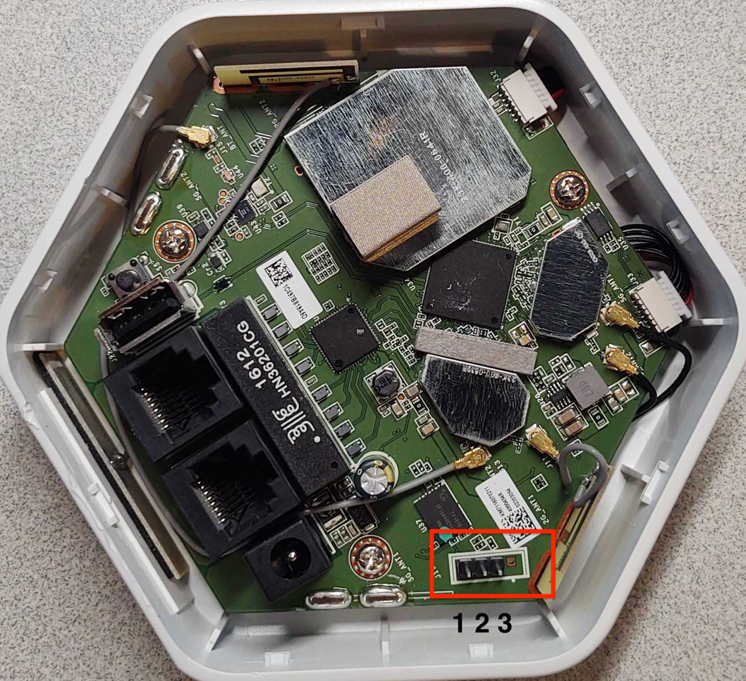
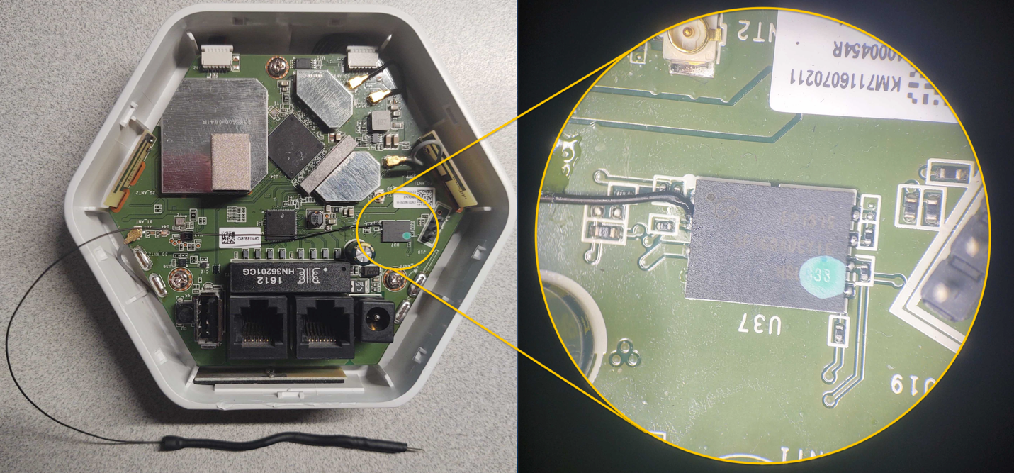
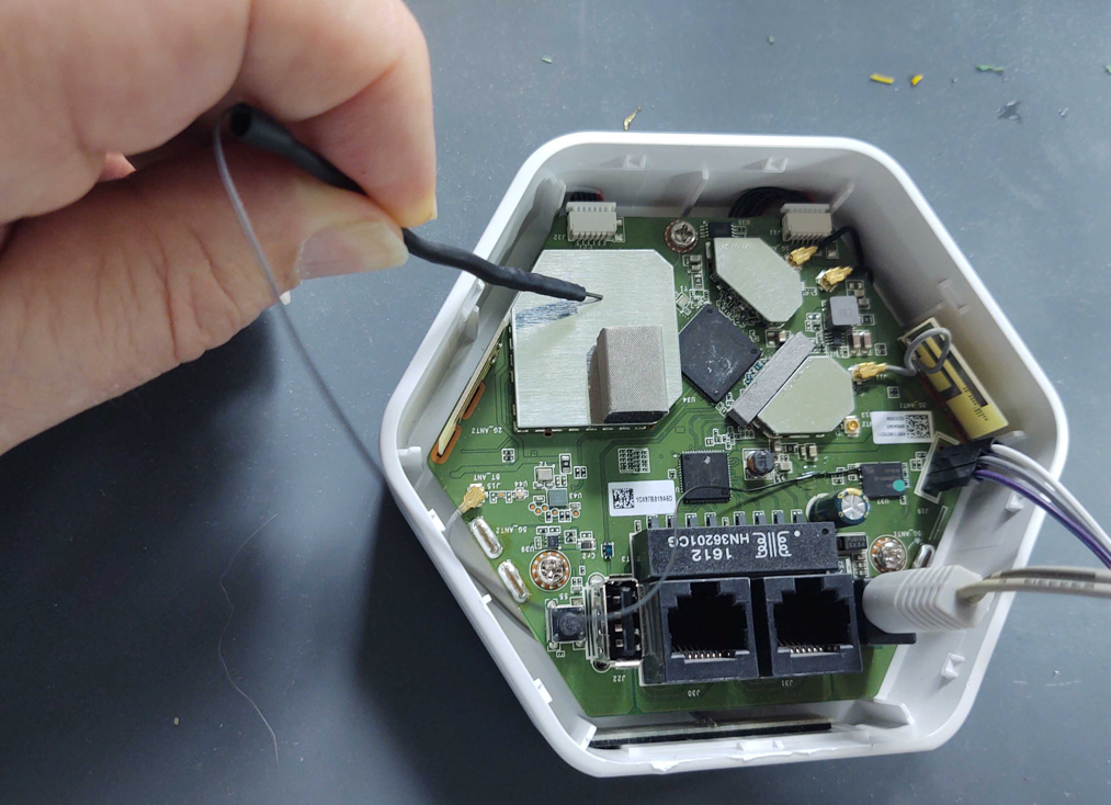
In our first post in this series, we covered the setup of Rapid7’s hands-on exercise at Defcon 29’s IoT Village. Last week, we discussed how to determine the UART status of the header we created and how to actually start hacking on the IoT device. The goal in this next phase of the IoT hacking exercise is to turn the console back on.

To accomplish this, we need to reenter the bootargs variable without the console setting. To change the bootargs variable, the “setenv” command should be used. In the case of this exercise, enter the following command as shown in Figure 16. You can see that the “console=off” has been removed. This will overwrite the current bootargs environment variable setting.

Hands-On IoT Hacking: Rapid7 at DefCon 29 IoT Village, Part 3
Figure 16: setenv command

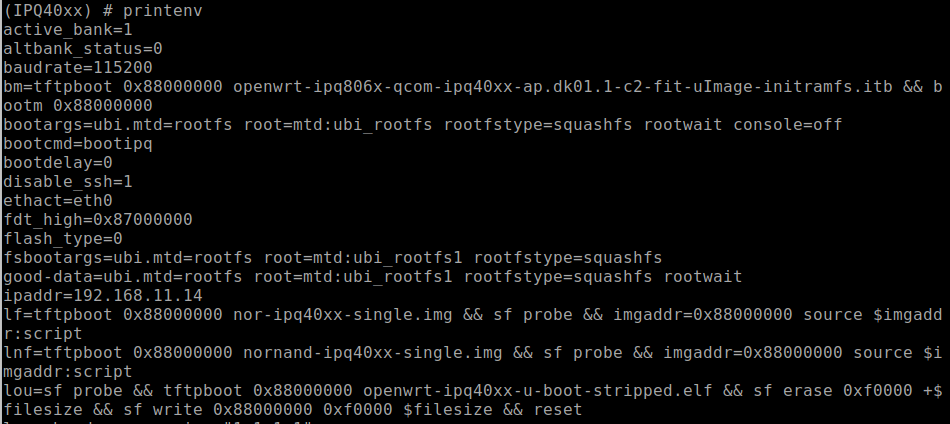
Once you’ve run this command, we recommend verifying that you’ve correctly made the changes to the bootargs variable by running the “printenv” command again and observing that the output shows that “console=off” has been removed. It is very common to accidentally mistype an environment variable, which will cause errors on reboot or just create an entirely new variable that has no usable value. The correct bootargs variable line should read as shown in Figure 17:

Hands-On IoT Hacking: Rapid7 at DefCon 29 IoT Village, Part 3
Figure 17: bootargs setting

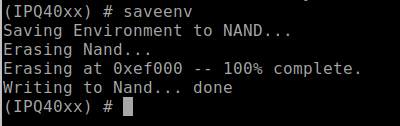
Once you’re sure the changes made to bootargs are correct, you’ll need to save the environment variable settings. To do this, you’ll use the “saveenv” command. Enter this command in the UART console, and hit enter. If you miss this step, then none of the changes made to the environment variables of U-Boot will be saved and all will be lost on reboot.

The saveenv should cause the U-Boot environment variables to be written to flash and return a response indicating it is being saved. An example of this is shown in Figure 18:

Hands-On IoT Hacking: Rapid7 at DefCon 29 IoT Village, Part 3
Figure 18: saveenv command response

Reboot and capture logs for review

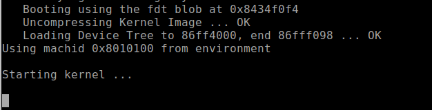
Once you’ve made all the needed changes to the U-Boot environment variables and saved them, you can reboot the device, observe console logs from the boot process, and save the console log data to a file for further review. The boot log data from the console will play a critical role in the next steps as you work toward gaining full root access to the device.

Next, reboot the systems. You can do this in a couple of different ways. You can either type the “reset” command within the U-Boot console and hit enter, which tells the MCU to reset and causes the system to restart, or just cycle the power on the device. After entering the reset command or power cycling the device, the device should reboot. The console should now be unlocked, and you should see the kernel boot up. If you still do not have a functioning console, you either entered the wrong data for bootargs or failed to save the settings with the “saveenv” command. I must admit I am personally guilty of both many times.

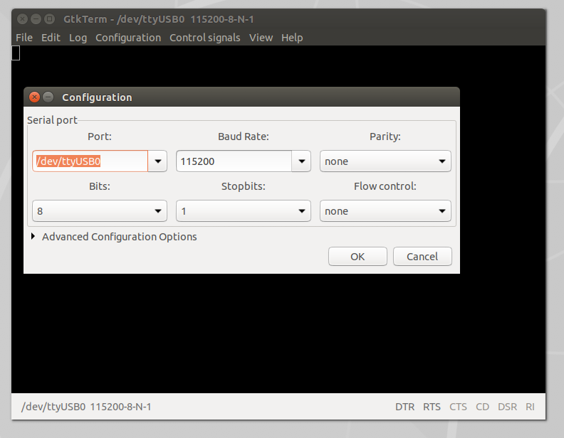
During the Defcon IoT Village exercise, we had the attendees capture console logs to a file for review using the following process in GtkTerm. If you are using a different serial console application, this process will be different for capture and saving logs.

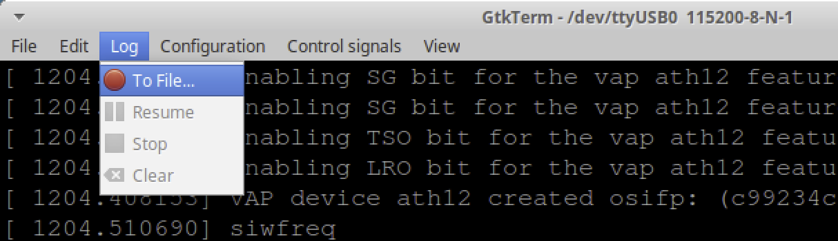
In GtkTerm, to capture logs for review, select “Log” on the task bar pulldown menu on GtkTerm as shown below in Figure 19:

Hands-On IoT Hacking: Rapid7 at DefCon 29 IoT Village, Part 3
Figure 19: Enable logging

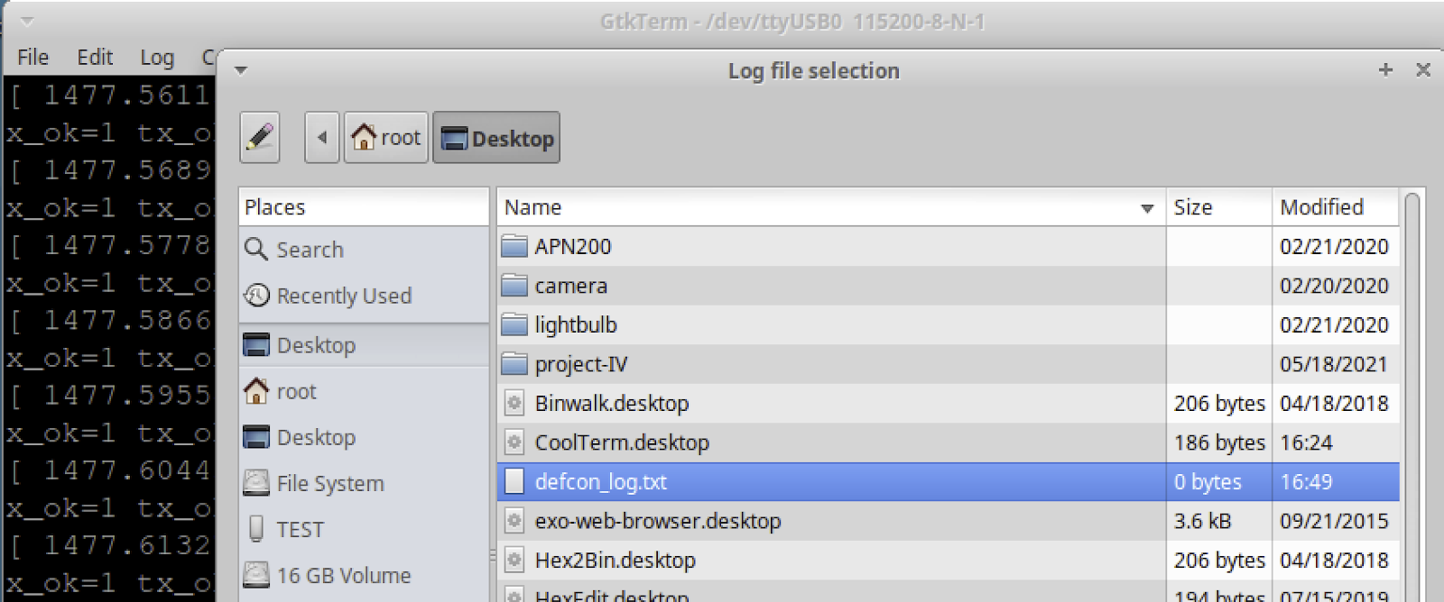
Once “Log” is selected, a window will pop up. From here, you need to select the file to write out the logs to. In this case, we had the attendees select the defcon_log.txt file on the laptops desktop as shown below in Figure 20:

Hands-On IoT Hacking: Rapid7 at DefCon 29 IoT Village, Part 3
Figure 20: Select defcon_log.txt file

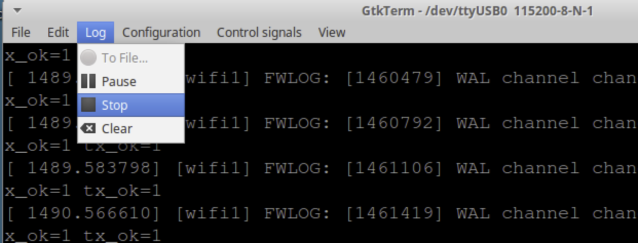
Once you’ve selected a log file, you should now start capturing logs to that file. From here, the device can be powered back on or restarted to start capturing logs for review. Let the system boot up completely. Once it appears to be up and running, you can turn off logging by selecting “Log” and then selecting “Stop” in the dropdown, as shown in Figure 21:

Hands-On IoT Hacking: Rapid7 at DefCon 29 IoT Village, Part 3
Figure 21: Stop log capture

Once logging is stopped, you can open the captured log file and review the contents. During the Defcon IoT Village exercise, we had the participants search for the keyword “failsafe” in the captured logs. Searching for failsafe should take you to the log entry containing the line:

  • “Press the [f] key and hit [enter] to enter failsafe mode”

This is a prompt that allows you to hit the “f” key followed by return to boot the system into single-user mode. You won’t find this mode on all IoT devices, but you will find it on some, like in this case with the LUMA device. Single-user mode will start the system up with limited functionality and is often used for conducting maintenance on an operating system — and, yes, this is root-level access to the device, but with none of the critical system function running that would allow network service, USB access, and applications that are run as part of the device’s normal operation features. Our goal later is to use this access and the following data to eventually gain full running system root access.

There is also another critical piece of data in the log file just shortly after the failsafe mode prompt, which we need to note. Approximately 8 lines below failsafe prompt, there is a reference to “rootfs_data” as shown in Figure 22:

Hands-On IoT Hacking: Rapid7 at DefCon 29 IoT Village, Part 3
Figure 22: Log review

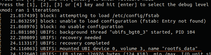
The piece of data we need from this line is the Unsorted Block Image File System (UBIFS) device number and the volume number. This will let us properly mount the rootfs_data partition later. With the LUMA, we found this to be one of the two following values.

  • Device 0, volume 2
  • Device 0, volume 3

Boot into single-user mode

Now that the captured logs have been reviewed, allowing us to identify the failsafe mode and the UBIFS mount data. The next step is to reboot the system into single-user mode, so we can work on getting full root access to the devices. To do this, you’ll need to monitor the system booting up in the UART console, watching for the failsafe mode prompt as shown below in Figure 23:

Hands-On IoT Hacking: Rapid7 at DefCon 29 IoT Village, Part 3
Figure 23: Failsafe mode prompt

When this prompt shows up, you will only have a couple of seconds to press the “f” key followed by the return key to get the system to launch into single-user root access mode. If you miss this, you’ll need to reboot and start over. If you’re successful, the UART console should show the following prompt (Figure 24):

Hands-On IoT Hacking: Rapid7 at DefCon 29 IoT Village, Part 3
Figure 24: Single-user mode

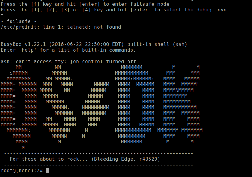
In single-user mode, you’ll have root access, although most of the partitions, applications, networks, and associated functions will not be loaded or running. Our goal will be to make changes so you can boot the device up into full operation system mode and have root access.

In our fourth and final installment of this series, we’ll go over how to configure user accounts, and finally, how to reboot the device and login. Check back with us next week!

NEVER MISS A BLOG

Get the latest stories, expertise, and news about security today.

Hands-On IoT Hacking: Rapid7 at DefCon IoT Village, Part 2

Post Syndicated from Deral Heiland original https://blog.rapid7.com/2021/10/28/hands-on-iot-hacking-rapid7-at-defcon-29-iot-village-pt-2/

Hands-On IoT Hacking: Rapid7 at DefCon IoT Village, Part 2

In our last post, we discussed how we set up Rapid7’s hands-on exercise at the Defcon 29 IoT Village. Now, with that foundation laid, we’ll get into how to determine whether the header we created is UART.

When trying to determine baud rate for IoT devices, I often just guess. Generally, for typical IoT hardware, the baud rate is going to be one of the following:

  • 9600
  • 19200
  • 38400
  • 57600
  • 115200

Typically, 115200 and 57600 are the most commonly encountered baud rates on consumer-grade IoT devices. Other settings that need to be made are data bits, stop bits, and parity bits. Typically, these will be set to the following standard defaults, as shown in Figure 5:

Hands-On IoT Hacking: Rapid7 at DefCon IoT Village, Part 2
Figure 5: Logic 2 Async Serial Decoder Settings

Once all the correct settings have been determined, and if the test point is UART, then the decoder in the Logic 2 application should decode the bit stream and reveal console text data for the device booting up. An example of this is shown in Figure 6:

Hands-On IoT Hacking: Rapid7 at DefCon IoT Village, Part 2
Figure 6: UART Decode of Channel 1

FTDI UART Setup

Once you’ve properly determined the header is UART and identified transmit, receive, and ground pins, you can next hook up a USB to UART FTDI and start analyzing and hacking on the IoT device. During the IoT Village exercise, we used a Shikra for UART connection. Unfortunately, the Shikra appears to no longer be available, but any USB to UART FTDI device supporting 3.3vdc can be used for this exercise. However, I do recommend purchasing a multi-voltage FTDI device if possible. It’s common to encounter IoT devices that require either 1.8, 3.3, or 5 vdc, so having a product that can support these voltage levels is the best solution.

The software we used to connect to the FTDI device for the exercise at Defcon IoT Village was GtkTerm running on an Ubuntu Linux — but again, any terminal software that supports tty terminal connection will work for this. For example, I have also used CoolTerm or Putty, which both work fine. So just find a terminal software that works best for you and substitute it for what is referenced here.

The next step is to attach the Shikra (pin out) or whatever brand of FTDI USB device you’re using to the UART header on Luma (Figure 7) using this table:

Shikra Pins Luma Header J19 Pins
Pin 1 TXT Pin 2 RCV
Pin 2 RCV Pin 3 TXT
Pin 18 GND Pin 1 GND

Hands-On IoT Hacking: Rapid7 at DefCon IoT Village, Part 2
Figure 7: LUMA UART PINOUT

Once the UART to USB device is connected to the LUMA, double-click on the GtkTerm icon located on the Linux Desktop and configure the application by selecting Configuration on the menu bar followed by Port in the drop-down menu. From there, set the Port (/dev/ttyUSB0) and Baud Rate (115200) to match the figure below (Figure 8), and click OK.

Hands-On IoT Hacking: Rapid7 at DefCon IoT Village, Part 2
Figure 8: Serial Port Settings

Once configured, power on the LUMA device. At this point, you should start to see the device’s boot process logged to the UART console. For the Defcon IoT hacking exercise, we had preconfigured the devices to disable the console, so once we loaded U-boot and started the system kernel image, the console became disabled, as shown in Figure 9:

Hands-On IoT Hacking: Rapid7 at DefCon IoT Village, Part 2
Figure 9: Console Stops at Kernel Starting

We made these changes so the attendees working on the exercise would experience a common setting often encountered, where the UART console is disabled during the booting process, and they’d have the chance to conduct another common attack that would allow them to break out of this lockdown.

For example, during the boot sequence, it’s often possible to force the device to break out of the boot process and to drop into a U-Boot console. For standard U-Boot, this will often happen when the Kernel image is inaccessible, causing the boot process to error out and drop into a U-Boot console prompt. This condition can sometimes be forced by shorting the data line (serial out) from the flash memory chip containing the kernel image to ground during the boot process. This prevents the boot process from loading the kernel into memory. Figure 5 shows a pin-out image of the flash memory chip currently in use on this device. The data out from the flash memory chip is Serial Out (SO) on pin 2.

Hands-On IoT Hacking: Rapid7 at DefCon IoT Village, Part 2
Figure 10: Flash Memory Pinout

Also, I would like to note that during the Defcon IoT Village exercises, I had a conversation with several like-minded IoT hackers who said that they typically do this same attack but use the clock pin (SCLK). So, that is another viable option when conducting this type of attack on an IoT device to gain access to the U-Boot console.

During our live exercises at Defcon IoT Village, to help facilitate the process of grounding the data line Pin 2 Serial Out (SO) — and to avoid ending up with a bunch of dead devices because of accidentally grounding the wrong pins — we attached a lead from pin 2 of the flash memory chip, as shown in Figure 11:

Hands-On IoT Hacking: Rapid7 at DefCon IoT Village, Part 2
Figure 11: Pin Glitch Lead Connected to Flash

To conduct this “pin glitch” attack to gain access to the U-Boot console, you will need to first power down the device. Then, restart the device by powering it back on while also monitoring the UART Console for the U-boot to start loading. Once you see the U-Boot loading, hold the shorting lead against the metal shielding or some other point of ground within the device, as shown in Figure 12:

Hands-On IoT Hacking: Rapid7 at DefCon IoT Village, Part 2
Figure 12: Short Pin2 Serial Out (SO) to Ground

Shorting this or the clock pin to ground will prevent U-Boot from being able to load the kernel. If your timing is accurate, you should be successful and now see U-Boot console prompt IPQ40xx, as shown below in Figure 13. Once you see this prompt, you can lay the shorting lead to the side. If this prompt does not show up, then you will need to repeat this process.

Hands-On IoT Hacking: Rapid7 at DefCon IoT Village, Part 2
Figure 13: U-Boot Console Prompt

With the LUMA device used in this example, this attack is more forgiving and easier to carry out successfully. The main reason, in my opinion, is because the U-Boot image and the kernel image are on separate flash memory chips. In my experience, this seems to cause more of a delay between U-Boot load and kernel loading, allowing for a longer window of time for the pin glitch to succeed.

Alter U-boot environment variables

U-boot environment variables are used to control the boot process of the devices. During this phase of the exercise, we used the following three U-Boot console commands to view, alter, and save changes made to the U-Boot environment variables to re-enable the console, which we had disabled before the exercise.

  • “Printenv” is used to list the current environment variable settings.
  • “Setenv” is used to create or modify environment variables.
  • “Saveenv” is used to write the environment variables back to memory so they are permanent.

When connected into the U-Boot console to view the device’s configured environment variables, the “printenv” command is used. This command will return something that looks like the following Figure 14 below. Scrolling down and viewing the environment settings will reveal a lot about how the device boot process is configured. In the case of the Defcon IoT Village, we had attendees pay close attention to the bootargs variable, because this is where the console was disabled from.

Hands-On IoT Hacking: Rapid7 at DefCon IoT Village, Part 2
Figure 14: printenv

With a closer look at the bootargs variable as shown below in Figure 15, we can see that the console had been set to off. This is the reason the UART console halted during the boot process once the kernel was loaded.

Hands-On IoT Hacking: Rapid7 at DefCon IoT Village, Part 2
Figure 15: bootargs Environment Variable Setting

In our third post, we’ll cover the next phase of our IoT Village exercise: turning the console back on and achieving single-user mode. Check back with us next week!

NEVER MISS A BLOG

Get the latest stories, expertise, and news about security today.

Hands-On IoT Hacking: Rapid7 at DefCon IoT Village, Part 1

Post Syndicated from Deral Heiland original https://blog.rapid7.com/2021/10/21/hands-on-iot-hacking-rapid7-at-defcon-iot-village-pt-1/

Hands-On IoT Hacking: Rapid7 at DefCon IoT Village, Part 1

This year, Rapid7 participated at the IoT Village during DefCon29 by running a hands-on hardware hacking exercise, with the goal of exposing attendees to concepts and methods for IoT hacking. Over the years, these exercises have covered several different embedded device topics, including how to use a Logic Analyzer, extracting firmware, and gaining root access to an embedded IoT device.

This year’s exercise focused on the latter and covered the following aspects:

  • Interaction with Universal Asynchronous Receiver Transmitter (UART)
  • Escaping the boot process to gain access to a U-Boot console
  • Modification of U-Boot environment variables
  • Monitoring system console during boot process for information
  • Accessing failsafe (single-user mode)
  • Mounting UBIFS partitions
  • Modifying file system for root access

While at DefCon, we had many IoT Village attendees request a copy of our exercise manual, so I decided to create a series of in-depth write-ups about the exercise we ran there, with better explanation of several of these key topic areas. Over the course of four posts, we’ll detail the exercise and add some expanded context to answer several questions and expand on the discussion we had with attendees at this year’s DefCon IoT Village.

The device we used in our exercise was a Luma Mesh WiFi device. The only change I made to the Luma devices for the exercise was to modify the U-Boot environment variables and add console=off to the bootargs variable to disable the console. I did this to add more complexity to the exercise and show a state that is often encountered.

Identify UART

One of the first steps in gaining root access to an IoT device is to identify possible entry points, such as a UART connection. In the case of our exercise, we performed this ahead of time by locating the UART connection and soldering a 2.54 mm header onto the board. This helped streamline the exercise, so attendees could complete it in a reasonable timeframe. However, the typical method to do this is to examine the device’s circuit board looking for an empty header, as in the example shown in Figure 1:

Hands-On IoT Hacking: Rapid7 at DefCon IoT Village, Part 1
Figure 1: Common 4 port 2.54mm header

This example shows 4 port headers. Although 4 port headers are common for UART, it is not always the rule. UART connections can be included in larger port headers or may not even have an exposed header. So, when you find a header that you believe to be UART, you’ll need to validate it.

To do this, we first recommend soldering male pins into the exposed socket. This will allow easier connectivity of test equipment. An example of this is shown in Figure 2:

Hands-On IoT Hacking: Rapid7 at DefCon IoT Village, Part 1
Figure 2: Soldered 2.54mm header

Once you’ve installed a header, I recommend using a logic analyzer to examine the connection for UART data. There are many different logic analyzers available on the market, which range in value from $12 or $15 to hundreds of dollars. In my case, I prefer using a Saleae logic analyzer.

The next step is to identify if any of the header pins are ground. To do this, first make sure the device is powered off. Then, you can use a multimeter set on continuity check and attach the ground lead “Black” to one of the metal shields covering various components on the circuit board, or one of the screws used to hold the circuit board in the cases — both often are found to be electrical ground.

Next, touch each pin in the header with the positive lead “Red” until the multimeter makes a ringing noise. This will indicate which pin is electrically ground. Once you’ve identified ground, you can attach the Logic Analyzer ground to that header pin and then connect the logic channel leads to the remaining pins, as shown in Figure 3:

Hands-On IoT Hacking: Rapid7 at DefCon IoT Village, Part 1
Figure 3: Logic Analyzer hooked up

Once hooked up, make sure the appropriate analyzer software is installed and running. In my case, I used Saleae’s Logic2. You can then power on the device and capture data on this header to analyze and identify:

  • Whether or not this header is UART
  • What the baud rate is
  • Which pin is transmit
  • Which pin is receive

As shown in the capture example in Figure 4, I captured 30 seconds of data during power-up of the device for channel 0 and 1. Here, we can see that data is shown on pin 1, which in this case indicates that channel 1, if determined to be UART, is most likely connected to the transmit pin. Since we are not sending any data to the device, channel 0 should show nothing, indicating it is most likely the receive pin.

Hands-On IoT Hacking: Rapid7 at DefCon IoT Village, Part 1
Figure 4: Logic-2 Capture 30 seconds

The next step is to make a final determination as to whether this is a UART header? If so, what is the baud rate?

We’ll cover this and the subsequent steps in our next post. Check back next week for more!

NEVER MISS A BLOG

Get the latest stories, expertise, and news about security today.

UPnP With a Holiday Cheer

Post Syndicated from Deral Heiland original https://blog.rapid7.com/2020/12/22/upnp-with-a-holiday-cheer/

UPnP With a Holiday Cheer

T’was the night before HaXmas,
when all through the house,
Not a creature was stirring, not even a mouse.
The stockings were hung by the chimney with care,
in hopes that St. Nicholas soon would be there.

This may be the way you start your holiday cheer,
but before you get started, let me make you aware.
I spend my holidays quite differently, I fear.
As a white-hat hacker with a UPnP cheer.

And since you may not be aware,
let me share what I learned with you,
so that you can also care,
how to port forward with UPnP holiday cheer.

Universal Plug and Play (UPnP) is a service that has been with us for many years and is used to automate discovery and setup of network and communication services between devices on your network. For today’s discussion, this blog post will only cover the port forwarding services and will also share a Python script you can use to start examining this service.

UPnP port forwarding services are typically enabled by default on most consumer internet-facing Network Address Translation (NAT) routers supplied by internet service providers (ISP) for supporting IPv4 networks. This is done so that devices on the internal network can automate their setup of needed TCP and UDP port forwarding functions on the internet-facing router, so devices on the internet can connect to services on your internal network.

So, the first thing I would like to say about this is that if you are not running applications or systems such as internet gaming systems that require this feature, I would recommend disabling this on your internet-facing router. Why? Because it has been used by malicious actors to further compromise a network by opening up port access into internal networks via malware. So, if you don’t need it, you can remove the risk by disabling it. This is the best option to help reduce any unnecessary exposure.

To make all this work, UPnP uses a discovery protocol known as Simple Service Discovery Protocol (SSDP). This SSDP discovery service for UPnP is a UDP service that responds on port 1900 and can be enumerated by broadcasting an M-SEARCH message via the multicast address 239.255.255.250. This M-SEARCH message will return device information, including the URL and port number for the device description file ‘rootDesc.xml’. Here is an example of a returned M-SEARCH response from a NETGEAR Wi-Fi router device on my network:

UPnP With a Holiday Cheer

To send a M-SEARCH multicast message, here is a simple Python script:

# simple script to enumerate UPNP devices
 
import socket
 
# M-Search message body
MS = \
    'M-SEARCH * HTTP/1.1\r\n' \
    'HOST:239.255.255.250:1900\r\n' \
    'ST:upnp:rootdevice\r\n' \
    'MX:2\r\n' \
    'MAN:"ssdp:discover"\r\n' \
    '\r\n'
 
# Set up a UDP socket for multicast
SOC = socket.socket(socket.AF_INET, socket.SOCK_DGRAM, socket.IPPROTO_UDP)
SOC.settimeout(2)
 
# Send M-Search message to multicast address for UPNP
SOC.sendto(MS.encode('utf-8'), ('239.255.255.250', 1900) )
 
#listen and capture returned responses
try:
    while True:
        data, addr = SOC.recvfrom(8192)
        print (addr, data)
except socket.timeout:
        pass

The next step is to access the rootDesc.xml file. In this case, this is accessible on my device via http://192.168.2.74:5555/rootDesc.xml. Looking at the M-SEARCH response above, we can see that the IP address for rootDesc.xml at 169.254.39.187.  169.254.*.* is known as an Automatic Private IP address. It is not uncommon to see an address in that range returned by an M-SEARCH request. Trying to access it will fail because it is incorrect. To actually access the rootDesc.xml file, you will need to use the device’s true IP address, which in my case was 192.168.2.74 and was shown in the header of the M-SEARCH message response.

Once the rootDesc.xml is returned, you will see some very interesting things listed, but in this case, we are only interested in port forwarding. If port forwarding service is available, it will be listed in the rootDesc.xml file as service type WANIPConnection, as shown below:

UPnP With a Holiday Cheer

You can open WANIPCn.xml on the same http service and TCP port location that you retrieved the rootDesc.xml file. The WANIPCn.xml file identifies various actions that are available, and this will often include the following example actions:

  • AddPortMapping
  • GetExternalIPAddress
  • DeletePortMapping
  • GetStatusInfo
  • GetGenericPortMappingEntry
  • GetSpecificPortMappingEntry

Under each of these actions will be an argument list. This argument list specifies the argument values that can be sent via Simple Object Access Protocol (SOAP) messages to the control URL at http://192.168.2.74:5555/ctl/IPConn, which is used to configure settings or retrieve status on the router device. SOAP is a messaging specification that uses a Extensible Markup Language (XML) format to exchange information.

Below are a couple captured SOAP messages, with the first one showing AddPortMapping. This will set up port mapping on the router at the IP address 192.168.1.1. The port being added in this case is TCP 1234 and it is set up to map the internet side of the router to the internal IP address of 192.168.1.241, so anyone connecting to TCP port 1234 on the external IP address of the router will be connected to port 1234 on internal host at 192.168.1.241.

UPnP With a Holiday Cheer

The following captured SOAP message shows the action DeletePortMapping being used to delete the port mapping that was created in the above SOAP message:

UPnP With a Holiday Cheer

To conclude this simple introduction to UPnP, SSDP, and port forwarding services, I highly recommend that you do not experiment on your personal internet-facing router or DSL modem where you could impact your home network’s security posture. But I do recommend that you set up a test environment. This can easily be done with any typical home router or Wi-Fi access point with router services. These can often be purchased used, or you may even have one laying around that you have upgraded from. It is amazing how simple it is to modify a router using these UPnP services by sending SOAP messages, and I hope you will take this introduction and play with these services to further expand your knowledge in this area. If you are looking for further tools for experimenting with port forwarding services, you can use the UPnP IGD SOAP Port Mapping Utility in  Metasploit to create and delete these port mappings.

But I heard him exclaim, ere he drove out of sight-
Happy HaXmas to all, and to all a good UPnP night

NEVER MISS A BLOG

Get the latest stories, expertise, and news about security today.

More HaXmas blogs