Post Syndicated from Deral Heiland original https://www.rapid7.com/blog/post/tr-beyond-devices-exploring-new-security-risks-interconnected-iot-ces-2026
Attending CES over the last several years has provided me with a valuable opportunity to observe how rapidly IoT technology continues to evolve across consumer and enterprise domains. This was my fourth year attending CES and I have seen a continued growth and advancement across multiple technology categories, from mobile devices and wearables, to AI-driven automation and robotics, to connected infrastructure.
This year’s show floor highlighted how deeply embedded “smart” technology has become within our everyday systems. As an IoT security researcher, what stood out to me most was not just the pace of innovation, but how increasingly interconnected these technologies have become, often relying on shared backend services, cloud platforms, and automated decision-making. These trends highlight the importance of examining not only individual devices, but the broader trust relationships and infrastructure architectures that support them.

AI-driven automation is no longer experimental
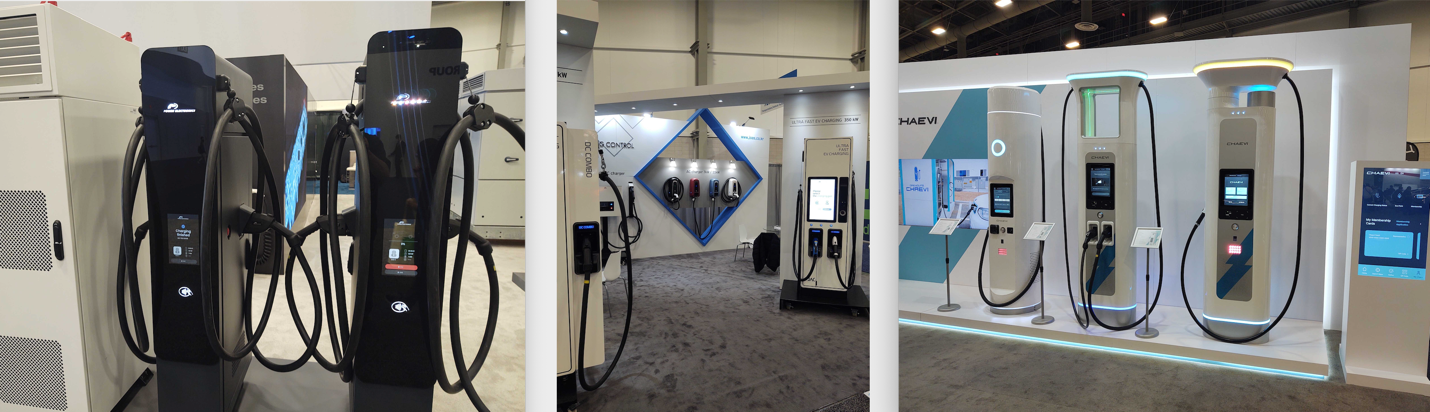
It was clear at CES 2026 that AI-driven automation is no longer experimental, it has become operational. Throughout automation, robotics, and transportation technology, decision-making processes are increasingly being delegated to backend AI systems that consume device telemetry and trigger real-world actions. From a security perspective, this marks a primary shift where trust relationships that were once local are now centralized, automated, and capable of impacting all devices within a larger ecosystem. The challenge moving forward doesn’t just involve securing devices; we will have to secure the data these devices produce, plus ensure that data is not altered or corrupted in a way that would impact all devices under the control of the backend AI systems.
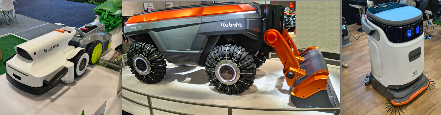
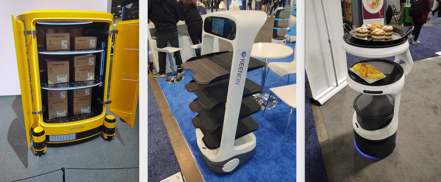
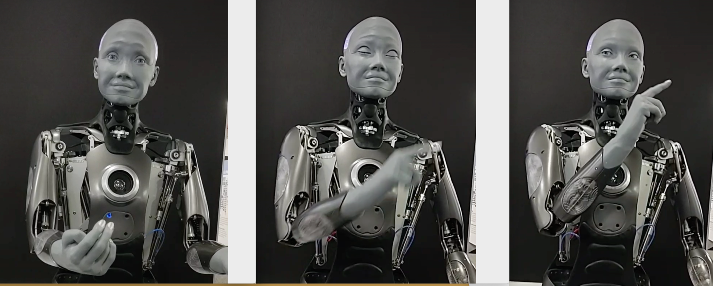
Robotics innovation demands urgent security action
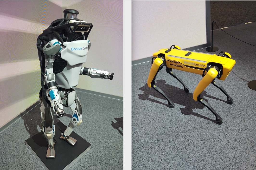
One of the more striking areas of progress has been in robotics, particularly in dexterity and fine motor control. Seeing robots play the piano or fold cloth highlighted how far robotic manipulation has come. Moving beyond their old rigid, pre-programmed motion toward a more adaptive interaction with our physical world. While we are still years away from anything resembling The Jetsons, these demonstrations show clear forward momentum. Before increasingly capable and autonomous robots become more deeply integrated into our world, we need to seriously address how to build security into the underlying technology. It’s also critical to maintain and secure the vast amount of data they will gather.

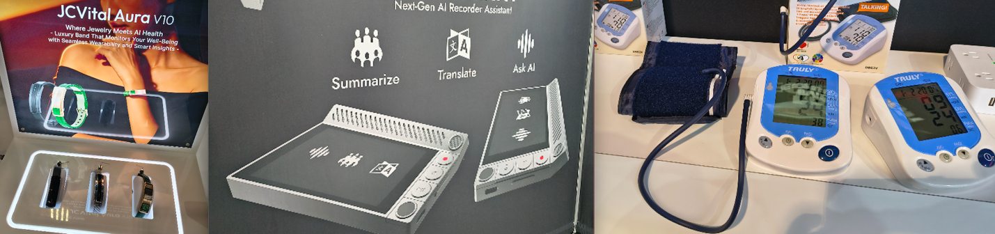
Mobile and wearable technologies are “always on”
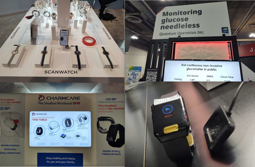
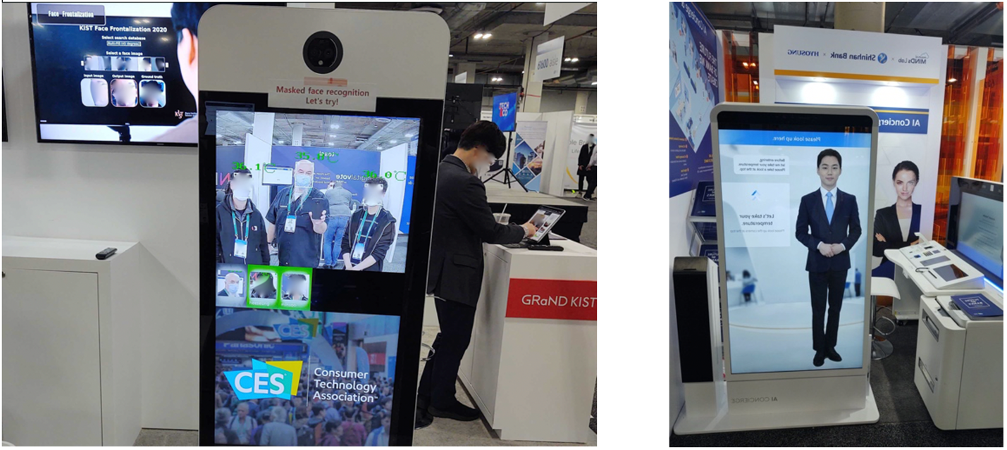
During CES this year, I also observed advances in mobile technology and wearables. While these devices have long been a staple of the show and continue to evolve incrementally each year, the growing integration of AI has noticeably expanded their capabilities. Features such as continuous sensing and adaptive behavior introduce new questions around security and privacy that go beyond traditional mobile threat models. As these technologies increasingly find their way into the hands of employees, they also raise important considerations for organizational security posture. This shift prompts a larger question CISOs should ask themselves: have our organization’s mobile device policies evolved alongside these technologies, or are they still grounded in smartphone-only assumptions from a decade ago?
For example, one of the most concerning mobile device technologies I observed was a device designed for use in corporate meetings that could automatically take notes, transcribe discussions, and translate conversations in real time. While such capabilities can clearly improve productivity and collaboration, especially in global organizations, they also introduce new security and privacy considerations. A device that is continuously listening, processing speech, and potentially transmitting data to backend cloud systems raises questions about where sensitive conversations are stored, how long that data is retained, and who ultimately has access to it. When such technologies are introduced into meeting rooms or business workflows, they essentially become an always-on sensor within the organization, and its presence may not be fully accounted for in most organizations with existing acceptable use policies. This highlights the need for organizations to reassess how emerging mobile and wearable technologies could impact their data protection, confidentiality, and overall security posture.
Conclusion: Building a new infrastructure of trust
My observations from CES 2026 clearly illustrate that the evolution of IoT has moved us beyond securing individual devices. The true security challenge now lies within the highly interconnected ecosystems, centralized AI-driven automation, and “always-on” data collection that underpin our increasingly “smart” world. The operationalization of AI and the rapid progress in robotics introduce centralized trust relationships and vast new data streams that are not yet matched by adequate security considerations.
This shift presents an urgent call to action for organizations. It’s time to aggressively reassess acceptable use and data protection policies to account for continuously sensing wearables, autonomous machinery, and the security of the backend services that control them all. The future of security is no longer just about protecting the perimeter; it is about securing the entire infrastructure of trust, data integrity, and automated decision-making that powers the next generation of technology.