All posts by Rohit Vashishtha

Integrate Tableau and PingFederate with Amazon Redshift using AWS IAM Identity Center

Post Syndicated from Rohit Vashishtha original https://aws.amazon.com/blogs/big-data/integrate-tableau-and-pingfederate-with-amazon-redshift-using-aws-iam-identity-center/

The series of posts on single sign-on to Amazon Redshift with AWS IAM Identity Center (successor to AWS Single Sign-On) integration continues from our prior post.

In this post, we outline a comprehensive guide for setting up single sign-on from Tableau desktop to Amazon Redshift using integration with IAM Identity Center and PingFederate as the identity provider (IdP) with an LDAP based data store, AWS Directory Service for Microsoft Active Directory.

Prerequisites

You should have the following prerequisites:

  1. A PingFederate account that has an active subscription. You need an admin role to set up the application on PingFederate. If you’re new to PingFederate, you can reach out to Ping Identity Sales.
  2. A working PingFederate server.
  3. Amazon Redshift Serverless workgroup or a provisioned Amazon Redshift data warehouse.
  4. Download and install the latest Redshift ODBC 2.X driver.
  5. Download and install Tableau Desktop 2024.1 or later
  6. Install Tableau Server 2023.3.9 or later. For Tableau Server installation, see Install and Configure Tableau Server.

Solution overview

PingFederate instance connects to IAM Identity Center using SAML. The users and groups in PingFederate are synced to IAM Identity Center using an open standard SCIM. After you set up SAML and SCIM, you will be able to enable single sign-on to Amazon Redshift from the AWS Management Console using Amazon Redshift Query Editor v2. This is achieved by creating an Identity Center application in the Amazon Redshift console.

To enable single sign-on to Amazon Redshift from outside of AWS using a third-party client like Tableau, you set up a trusted token issuer token exchange using OIDC standard.

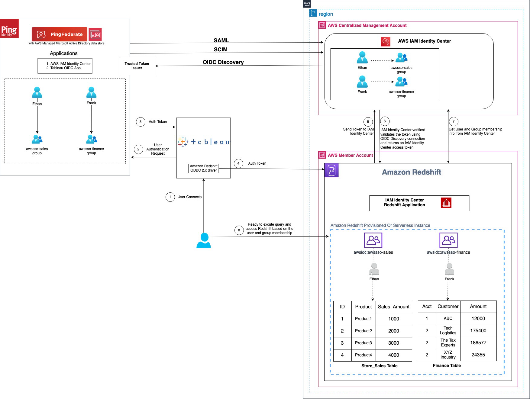
Figure 1 : Solution overview for Tableau integration with Amazon Redshift using IAM Identity Center and Ping Federate

The workflow, shown in the preceding figure, includes the following steps:

  1. The user configures Tableau to access Amazon Redshift using IAM Identity Center authentication.
  2. On a user sign-in attempt, Tableau initiates a browser-based OAuth flow and redirects the user to the PingFederate sign in page to enter the sign-in credentials. Password validation is done against the AWS Managed Microsoft AD data store.
  3. On successful authentication, PingFederate issues an authentication token (ID and access token) to Tableau.
  4. The Amazon Redshift driver then makes a call to the Amazon Redshift-enabled Identity Center application and forwards the access token.
  5. Amazon Redshift passes the token to Identity Center and requests an access token.
  6. Identity Center verifies the token using the OIDC discovery connection to the trusted token issuer and returns an Identity Center-generated access token for the same user. In the preceding figure, trusted token issuer (TTI) is the PingFederate server that Identity Center trusts to provide tokens that third-party applications like Tableau use to call AWS services.
  7. Amazon Redshift then uses the token to obtain the user and group membership information from Identity Center.
  8. Tableau user will be able to connect with Amazon Redshift and access data based on the user and group membership returned from Identity Center. The user and group settings in the LDAP-based AWS Managed Microsoft AD data store for PingFederate are propagated to identity center using SCIM protocol for outbound provisioning.

Walkthrough

In this walkthrough, you will use the following steps to build the solution:

  1. SAML and SCIM set up between PingFederate and IAM Identity Center
  2. Connect to Amazon Redshift using Query Editor v2
  3. Configure identity federation from a third-party client
    1. Create an access token manager and access token mapping
    2. Create an OIDC policy
    3. Create an OAuth client
    4. Set up a PingFederate Authorization Server
    5. Policy Contract Grant Mapping
    6. Collect PingFederate information
    7. Set up a trusted token issuer in IAM Identity Center
    8. Set up client connections and trusted token issuers in Amazon Redshift
    9. Configure Tableau OAuth config files for PingFederate to integrate with Amazon Redshift using IAM Identity Center
    10. Install a Tableau OAuth config file on a client machine for Tableau Desktop
    11. Install a Tableau OAuth config file for a site on Tableau Server or Tableau Cloud
    12. Federate to Amazon Redshift from Tableau Desktop using Identity Center
    13. Federate to Amazon Redshift from Tableau Server using Identity Center authentication

SAML and SCIM set up between PingFederate and IAM Identity Center

IAM Identity Center integration with PingFederate starts with SAML set up followed by SCIM.

  1. Set up SAML 2.0 for SP Connection of type Browser SSO (single sign-on) in PingFederate.
  2. Set up SCIM 2.0 for outbound provisioning. It will sync the users and groups created in an LDAP based data store like AWS managed Microsoft AD for PingFederate to the users and groups in IAM Identity Center.

The implementation for the cloud based IdP option PingOne is not in scope of this post and follows steps similar to those described in Integrate IdP with Amazon Redshift Query Editor v2 using AWS IAM Identity Center for seamless Single Sign-On.

Further details of SAML and SCIM set up are as follows.

    1. Install PingFederate Server.
    2. Set up IAM Identity center integration by following the Ping documentation including the download for Identity Center integration files.
      1. Deploy the integration files to your PingFederate installation.
      2. Enable provisioning and configure IdP Browser SSO (SAML connection). (You can implement Browser SSO connection only using IAM Identity Center metadata file.)
        1. Under System > Server > Protocol Settings > Federation Info BASE_URL field, use the publicly accessible fully qualified domain name of the PingFederate server.
        2. Create an LDAP based data store (the name used in this example is AWSManagedMSAD) because SCIM 2.0 protocol for outbound provisioning only works with LDAP based data stores with PingFederate. If you are using a cloud-based solution like PinOne, you can set up outbound provisioning in PingOne itself. Thus for this writing, we have used AWS Managed Microsoft AD as a data store created using AWS Directory Service.
        3. Create a password credential validator (name used in this example is awsmanagedmsadpassval) and IdP adapters (name used in this example is awsmanagedmsadadapter) for your data store as applicable.
        4. Create an SP connection of type Browser SSO using the sp-saml-metadata.xml file as explained in creating a provisioning connection.
      3. Export SAML metadata from PingFederate.
      4. Register PingFederate as an IdP in Identity Center.
      5. Navigate back to the connection saved in step b, and configure outbound provisioning.
    3. Enable provisioning in IAM Identity Center by following step 1 in the documentation.
    4. Then, configure provisioning in PingFederate by following step 2 in the documentation.
    5. Optionally, you can configure and pass user attributes from PingFederate for access control in Identity Center.

Next, connect to Amazon Redshift using its native query editor, Query Editor v2, to validate AWS services’ connectivity using IAM Identity Center.

Connect to Amazon Redshift using Query Editor v2

Complete the Walkthrough section of IAM Identity Center integration with Amazon Redshift, which will set up your Amazon Redshift connectivity with Query Editor v2.

If you need further help with SAML and SCIM set up, and connecting to Amazon Redshift using Query Editor v2, you can also follow step by step guided demo video single sign-on to Amazon Redshift with IAM IDC integration using PingFederate with AWS Managed MSAD Demo

Configure identity federation from a third-party client

Configure identity federation enabled by IAM Identity Center from IdP PingFederate to the service provider Amazon Redshift using an external client like Tableau. The following steps in the PingFederate admin console and Identity Center guide you through the identity federation process.

Create an access token manager and access token mapping

To map PingFederate attributes to OAuth access tokens and OpenID Connect ID (OIDC) tokens, create an access token manager and token mapping. For complete details and set up based on your security needs, see Token mapping in PingFederate, which explains access token management in detail. Complete the following steps to create a token manager.

  1. In the PingFederate administrative console, go to Applications > OAuth > Access Token Management, and choose Create New Instance.
  2. In Type tab,
    1. Enter an Instance Name and Instance ID of your choice, for example TrustedTokenIssuerMgr.
    2. Select the Type from drop down list as JSON Web Tokens, commonly called JWT.
    3. Leave Parent instance as None and choose Next.
  3. In Instance configuration tab,
    1. Under Certificates, select Add a new row to ‘Certificates’, select the certificate for token manager from the drop-down list, enter a Key ID such as certkey, and choose Update under Action. You can create a new certificate by navigating to Security > Certificate & Key Management > Signing & Decryption Keys & Certificates > Create New.
    2. Select Use Centralized Signing Key.
    3. In JWS Algorithm, select RSA using SHA-256.
    4. Select Enable Token Revocation. Leave everything else as default and choose Next.
  4. Under Session Validation tab,
    1. Select Include Session Identifier in Access Token.
    2. Select Check for valid authentication session.
    3. Leave other choices as is and choose Next.
  5. In the Access Token Attribute Contract tab, leave the Subject Attribute Name as the e default and proceed to Extend the Contract to add the following attribute and values.
    1. Enter aud, leave multi-value unchecked. Choose Add under Action.
    2. Repeat the same to enter email, exp, iss, sub. When completed, choose Next.
  6. On each of Resource URIs and Access Control tabs, leave as is and choose Next.
  7. On the Summary tab, review your changes and choose Save. An instance name with the name you provided, like TrustedTokenIssuerMgr appears in Applications > Oauth > Access Token Management.

Figure 2 : Access Token Management Configuration Summary

  1. Navigate to Applications > OAuth > Access Token Mappings, select the default Context and Access Token ManagerTrustedTokenIssuerMgr that was created in the previous step. Choose Add Mapping.
  2. Leave Attribute Sources & User Lookup as is and choose Next.
  3. Under Contract Fulfillment tab,
    1. For Contract aud, select Text from the Source, and enter the Value as AWSIdentityCenter.
    2. For Contract email, select Persistent Grant from the Source, and Value as email.
    3. For Contract exp, select Persistent Grant from the Source, and Value as EXPIRES_AT.
    4. For Contract iss, select Text from the Source, and enter your base URL as the Value, like https://yourwebsite.domain.com, the same as in System > Server > Protocol Settings > BASE URL.
    5. For Attribute Contract sub, select Persistent Grant from the Source, and Value as USER_KEY.
    6. Choose on Next.
  4. Leave Issuance Criteria as is and choose Next.
  5. On the Summary tab, review all your changes and choose Save. A new default Context with Access Token Manager if TrustedTokenIssuerMgr appears in Applications > OAuth > Access Token Mappings.

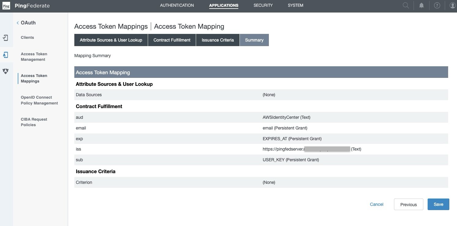
Figure 3: Access Token Mappings Summary

Create an OIDC policy

For complete details and set up based on your security needs, see to Open ID connect (OIDC) policy management in PingFederate. Complete the following steps to set up an OIDC policy.

  1. In the PingFederate administrative console, go to Applications > OAuth > OpenID Connect Policy Management, and choose Add Policy.
  2. In the Manage Policy tab,
    1. Enter the Policy ID and Name of your choice, for example OIDCPolicy.
    2. Select the Access Token Manager from drop down list created in the previous section—TrustedTokenIssuerMgr.
    3. Select Include Session Identifier in ID Token
    4. Select Include User Info in ID Token
    5. Select Return ID Token on Refresh Grant
    6. Leave others as is and choose Next.
  3. In the Attribute Contract tab, keep only the required attributes in extended contract and delete the others.
    1. Leave the sub attribute under Attribute Contract as is.
    2. Under Extend the contract, choose delete for all attributes except email. choose Next.
  4. In the Attribute Scopes tab,
    1. Select openid from the Scope list.
    2. Select email from Attributes.
    3. Choose Add from Actions. Choose Next.
  5. Leave Attribute Sources & User Lookup as is and choose Next.
  6. In Contract Fulfillment tab,
    1. For Attribute Contract email, select Persistent Grant from the Source, and Value as email.
    2. For Attribute Contract sub, select Persistent Grant from the Source, and Value as USER_KEY.
    3. Choose Next.
  7. Leave Issuance Criteria as is and choose Next.
  8. On the Summary tab, review your changes and choose Save. A policy ID with the name you provided, like OIDCPolicy, appears in Applications > OauthOpenID Connect Policy Management.

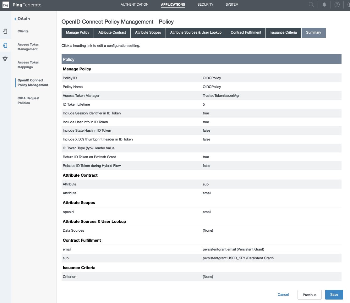
Figure 4 : OpenID Connect Policy Management Summary

Create OAuth client

For complete details and set up based on your security needs, see configure an OAuth client in PingFederate, which explains each field in detail. Complete the following steps to create an OAuth client.

  1. In the PingFederate administrative console, go to Applications > OAuth > Clients, and choose Add Client.
  2. In the Client ID field, enter a unique, immutable client ID. We use tableauredshiftpingfed as the name in this example.
  3. Enter a Name and Description for the client.
  4. Select a Client Authentication method. You can select from NoneClient TLS CertificatePrivate Key JWT, or Client Secret. For this scenario, select Client Secret. Choose Generate Secret to create a new one or use select Change secret to create your own.
  5. Leave Request object signing algorithm set to Allow Any. You can override to use the algorithm of your choice if needed.
  6. In the Redirect URIs field, add each of the following values.
    1. http://localhost:8080/authorization-code/callback
    2. http://localhost:55556/Callback
    3. http://localhost:55557/Callback
    4. http://localhost:55558/Callback
    5. http://localhost/auth/add_oauth_token
  7. Select Restrict common scopes. Restrict scopes by selecting the checkboxes for email, offline_access, openid, and profile as required.
  8. In Logo URL, optionally enter the URL for logo you want to display on the User Grant Authorization and Revocation pages.
  9. In the Allowed Grant Types list, you can choose from a list of authorization options. In this example, select Authorization code. Optionally, you can select Implicit, Refresh Token, and Client Credentials.
  10. Under Default access token manager, select the access token manager TrustedTokenIssuerMgr created in the earlier section.
  11. Select the Restrict box for Restrict to default access token manager.
  12. Customize Persistent grants max lifetime to match your requirements. Set it to 12 hours for this example by using the third radio button.
  13. For Openid connect, choose your preferred ID token signing algorithm. Select RSA using SHA-256 for this example. Optionally, for Policy you can choose the OIDC policy created in the earlier section.
  14. Leave the remaining settings as default and choose Save.

Figure 5 : OAuth Client Configuration

The Tableau Desktop redirect URLs should always use localhost. The following example, also use localhost for the Tableau Server hostname to simplify testing in a test environment. For this setup, you should also access the server at localhost in the browser. In a production environment, or Tableau Cloud, you should use the full hostname that your users will use to access Tableau on the web, along with HTTPS. If you already have an environment with HTTPS configured, you can skip the localhost configuration and use the full hostname from the start.

Set up a PingFederate authorization server

For complete details and set up based on your security needs, see PingFederate authorization server settings in PingFederate. Complete the following steps to configure an authorization server.

  1. In the PingFederate administrative console, go to System > OAuth Settings > Authorization Server Settings, and make following changes.
  2. Leave the initial configurations as default and scroll down to Persistent Grant Extended Attributes, add Attribute email.
  3. For OAuth Administrative Web Services Settings, in Password Credential Validator, select awsmanagedmsadpassval that you created in the SAML and SCIM set up section.
  4. For Persistent Grant Management API,
    1. In Access Token Manager, select the TrustedTokenIssuerMgr created earlier.
    2. In Required Scope, select openid.
  5. Leave remaining the settings as default and choose Save.

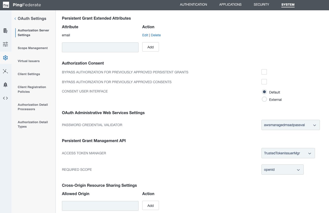
Figure 6 : PingFederate Authorization Server Setting

Policy contract grant mapping

For complete details and set up based on your security needs, see Grant contract mapping in PingFederate. For this illustration, we set up a policy contract grant mapping for authentication in a three-step process.

Step 1: Create a policy contract

  1. In the PingFederate administrative console, go to Authentication > Policies > Policy Contracts, and choose Create New Contract.
  2. In Contract Info tab, enter a name. For this example, we use OIDCPolicyContract.
  3. In Contract Attributes tab, choose Extend the Contract to add email attribute.
  4. Review and choose Save.

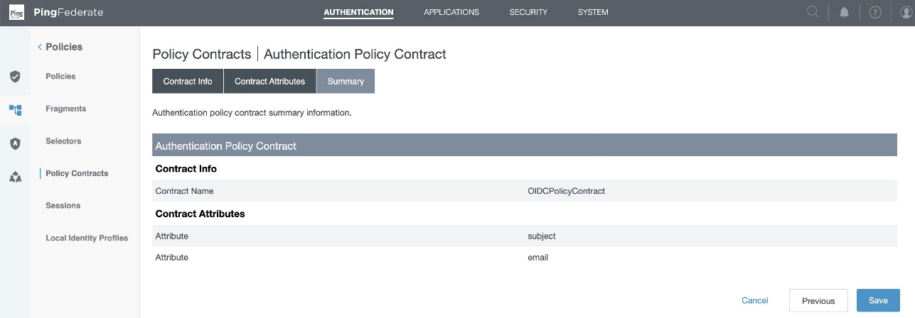
Figure 7 : Policy Contract Summary

Step 2: Add authentication policy

  1. In the PingFederate administrative console, go to Authentication > Policies > Policies, and choose Add Policy.
  2. Enter a policy name. In this example, we use OAuthOIDCPolicy.
  3. In the Policy drop down, select IdP Adapter and select the awsmanagedmsadadapter that you created in the SAML and SCIM set up section.
  4. Set FAIL to Done and under SUCCESS, select Policy Contracts from the drop-down menu and select the OIDCPolicyContract created in step 1. Choose Done.

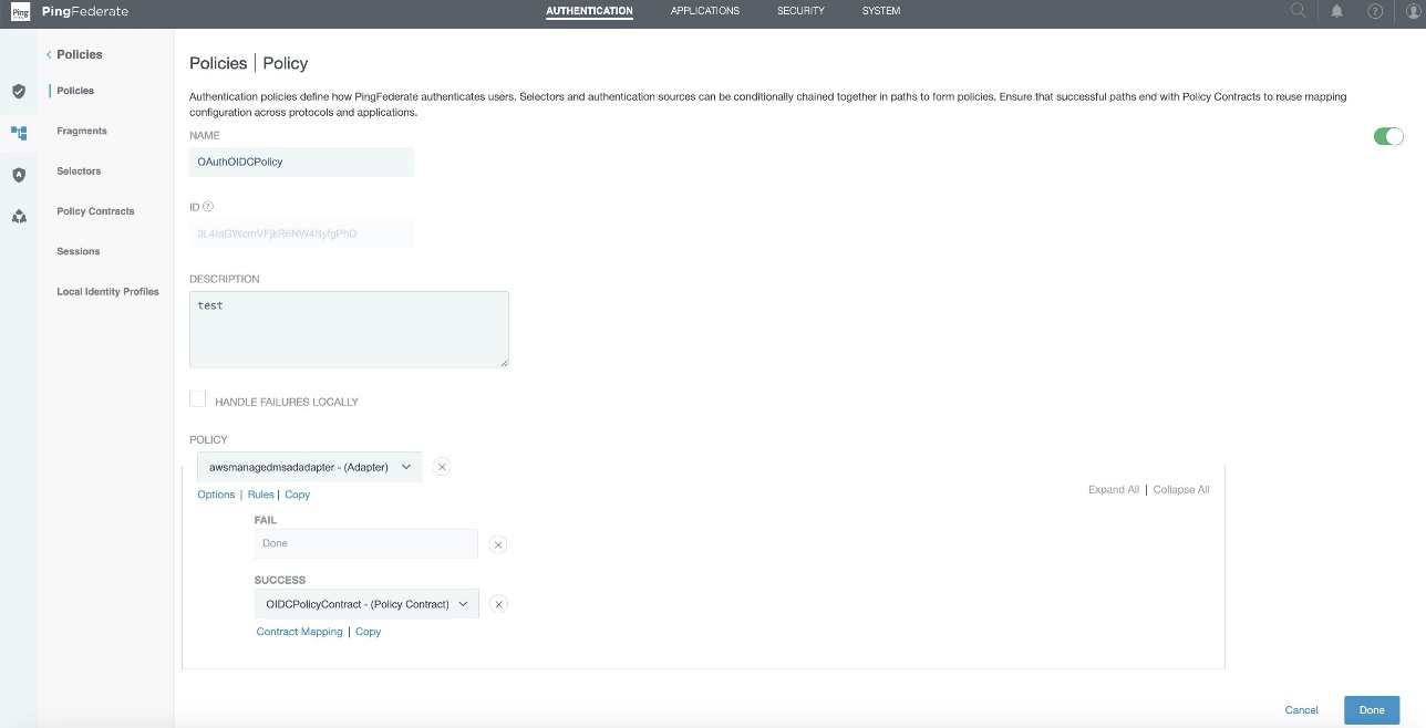
Figure 8 : Authentication Policy Configuration

Step 3: Policy contract grant mapping

  1. In the PingFederate administrative console, go to Authentication > OAuth > Policy Contract Grant Mapping, and under Mappings, select OIDCPolicyContract created in Step1 and choose Add Mapping.
  2. On the Attribute Sources & User Lookup tab, choose Next.
  3. In the Contract Fulfillment tab,
    1. For Contract USER_KEY, pick Authentication Policy Contract from the Source, and Value as subject.
    2. For Contract USER_NAME, pick Authentication Policy Contract from the Source, and Value as subject.
    3. For Contract email, pick Authentication Policy Contract from the Source, and Value as email.
    4. Choose Next.
  4. Leave Issuance Criteria as is, review and choose Save.

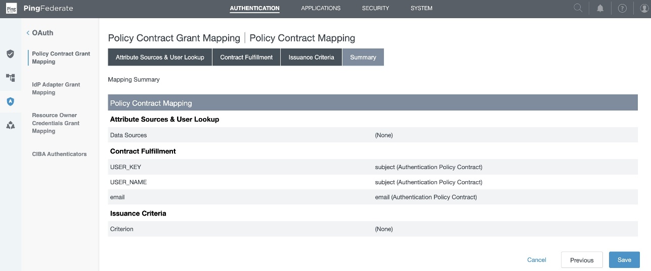
Figure 9 : Policy Contract Grant Mapping Summary

Collect PingFederate information

To configure your PingFederate with IAM Identity Center and Amazon Redshift, collect the following parameters. If you don’t have these parameters, contact your PingFederate admin.

  1. Issuer URL, auth URL (authUri), and token URL (tokenUri).

You can get these values from the OIDC IdP URL: https://pingfedserver.example.com/.well-known/openid-configuration. Open this URL in a web browser, replacing pingfedserver.example.com with your IdP server name.

The following is an example screenshot of IdP attributes using OIDC IdP URL where:

  • The issuer URL corresponds to the issuer
  • The auth URL (authUri) corresponds to authorization_endpoint
  • The token URL (tokenUri) corresponds to token_endpoint

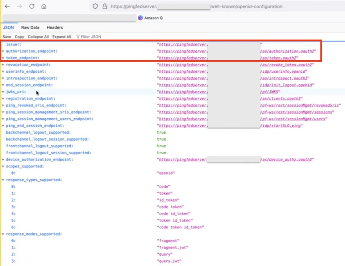
Figure 10 : Screenshot of IdP Attributes

  1. Audience value

To get the Audience value from PingFederate, sign in as an admin to PingFederate and navigate to the following path to get the audience value that you created during access token mapping creation in PingFederate:

Applications > OAuth > Access Token Mappings > TrustedTokenIssuerMgr → Summary > aud

Figure 11 : Access Token Mapping

Set up a trusted token issuer in IAM Identity Center

Switch from the PingFederate console to the IAM Identity Center console for the AWS side of configuration. Start by adding a trusted token issuer (TTI), which makes it possible to authorize Tableau to make requests on behalf of their users to access data in Amazon Redshift. A TTI is an OAuth 2.0 authorization server that issues tokens to applications that initiate requests (requesting applications). The tokens authorize these applications to initiate requests on behalf of their users to a receiving application (an AWS service). In this step, you create a TTI in the central management account. To create a TTI,

  1. Open the AWS Management Console and navigate to IAM Identity Center, and then to the Settings page.
  2. Select the Authentication tab and under Trusted token issuers, choose Create trusted token issuer.
  3. On the Set up an external IdP to issue trusted tokens page, under Trusted token issuer details, do the following:
    • For Issuer URL, enter the OIDC discovery URL of the external IdP that will issue tokens for trusted identity propagation. You can get issuer the URL as mentioned in step 1 of the preceding section Collect PingFederate information.
  4. For Trusted token issuer name, enter a name to identify this TTI in Identity Center and in the application console.
  5. Under Map attributes, do the following:
    1. For the identity provider attribute, select an attribute from the list to map to an attribute in the Identity Center identity store. You can select Email, Object Identifier, Subject, and Other.
    2. For Identity Center attribute, select the corresponding attribute for the attribute mapping.
  6. Under Tags (optional), choose Add new tag, enter a value for Key, and optionally for Value. For information about tags, see Tagging AWS IAM Identity Center resources.

The following figure shows the set up for TTI:

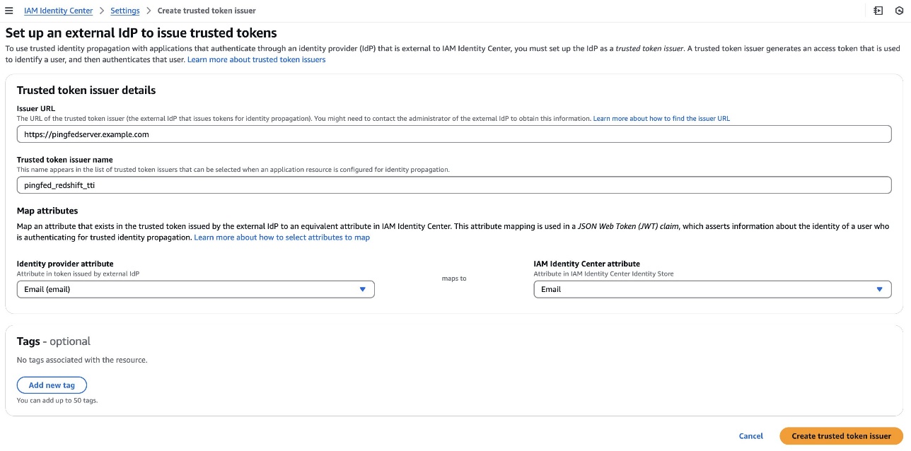
Figure 12 : Configuring Trusted Token Issuer

Set up client connections and trusted token issuers in Amazon Redshift

In this step, the Amazon Redshift applications that exchange externally generated tokens must be configured to use the TTI you created in the previous step. Also, the audience claim (or aud claim) from PingFederate must be specified. In this example, you are configuring the Amazon Redshift application in the member account where the Amazon Redshift cluster or serverless instance exists.

  1. Select IAM Identity Center connection from the Amazon Redshift console menu.
  2. Select the Amazon Redshift application that you created as part of the prerequisites.
  3. Select the Client connections tab and choose Edit.
  4. Choose Yes under Configure client connections that use third-party IdPs.
  5. Select the checkbox for Trusted token issuer that you created in the previous section.
  6. Enter the Aud claim value under Configure selected trusted token issuers. For example, AWSIdentityCenter. You can get the audience value from the PingFederate path: Applications > OAuth > Access Token Mappings > TrustedTokenIssuerMgr > Summary > aud.
  7. Choose Save.

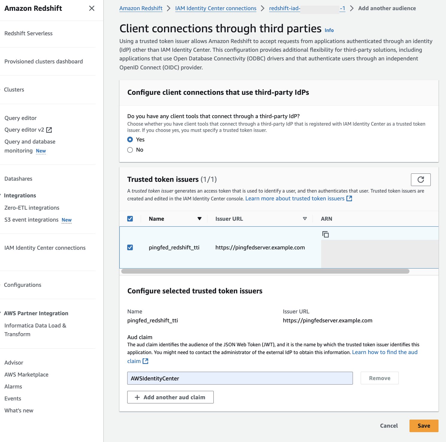
Figure 13 : Configure Audience Value in Amazon Redshift

At this point, your IAM Identity Center, Amazon Redshift, and PingFederate configuration are complete. Next, you need to configure Tableau.

Configure Tableau OAuth config files for PingFederate to integrate with Amazon Redshift using IAM Identity Center

This XML file used in this section will be used for all the Tableau products like Tableau Desktop, Server and Cloud.

To integrate Tableau with Amazon Redshift using IAM Identity Center, you need to use a custom XML file. In this step, you will use the following XML and replace the values starting with a $ sign and highlighted in bold. The rest of the values can be kept as it is or you can modify them based on your specific needs. For detailed information on each of the elements in the file, see the Tableau documentation on GitHub.

You can get authUri and tokenUri as mentioned in step 1 of preceding section, Collect PingFederate information.

<?xml version="1.0" encoding="utf-8"?>
<pluginOAuthConfig>
  <dbclass>redshift</dbclass>
  <oauthConfigId>custom_redshift_pingfed</oauthConfigId>
  <clientIdDesktop></clientIdDesktop>
  <clientSecretDesktop></clientSecretDesktop>
  <redirectUrisDesktop>http://localhost:55556/Callback</redirectUrisDesktop>
  <redirectUrisDesktop>http://localhost:55557/Callback</redirectUrisDesktop>
  <redirectUrisDesktop>http://localhost:55558/Callback</redirectUrisDesktop>
  <authUri>https://.com/as/authorization.oauth2</authUri>
  <tokenUri>https://.com/as/token.oauth2</tokenUri>
  <scopes>openid</scopes>
  <scopes>email</scopes>
  <scopes>profile</scopes>
  <scopes>offline_access</scopes>
  <capabilities>
    <entry>
      <key>OAUTH_CAP_FIXED_PORT_IN_CALLBACK_URL</key>
      <value>true</value>
    </entry>
    <entry>
      <key>OAUTH_CAP_PKCE_REQUIRES_CODE_CHALLENGE_METHOD</key>
      <value>true</value>
    </entry>
    <entry>
      <key>OAUTH_CAP_REQUIRE_PKCE</key>
      <value>true</value>
    </entry>
    <entry>
      <key>OAUTH_CAP_SUPPORTS_STATE</key>
      <value>true</value>
    </entry>
    <entry>
      <key>OAUTH_CAP_CLIENT_SECRET_IN_URL_QUERY_PARAM</key>
      <value>true</value>
    </entry>
    <entry>
      <key>OAUTH_CAP_SUPPORTS_GET_USERINFO_FROM_ID_TOKEN</key>
      <value>true</value>
    </entry>
  </capabilities>
  <accessTokenResponseMaps>
    <entry>
      <key>ACCESSTOKEN</key>
      <value>access_token</value>
    </entry>
    <entry>
      <key>REFRESHTOKEN</key>
      <value>refresh_token</value>
    </entry>
    <entry>
      <key>id-token</key>
      <value>id_token</value>
    </entry>
    <entry>
      <key>access-token-issue-time</key>
      <value>issued_at</value>
    </entry>
    <entry>
      <key>access-token-expires-in</key>
      <value>expires_in</value>
    </entry>
    <entry>
      <key>username</key>
      <value>email</value>
    </entry>
  </accessTokenResponseMaps>
</pluginOAuthConfig>

The following is the example XML:

<?xml version="1.0" encoding="utf-8"?>
<pluginOAuthConfig>
  <dbclass>redshift</dbclass>
  <oauthConfigId>custom_redshift_pingfed</oauthConfigId>
  <clientIdDesktop>tableauredshiftpingfed</clientIdDesktop>
  <clientSecretDesktop></clientSecretDesktop>
  <redirectUrisDesktop>http://localhost:55556/Callback</redirectUrisDesktop>
  <redirectUrisDesktop>http://localhost:55557/Callback</redirectUrisDesktop>
  <redirectUrisDesktop>http://localhost:55558/Callback</redirectUrisDesktop>
  <authUri>https://pingfedserver.example.com/as/authorization.oauth2</authUri>
  <tokenUri>https://pingfedserver.example.com/as/token.oauth2</tokenUri>
  <scopes>openid</scopes>
  <scopes>email</scopes>
  <scopes>profile</scopes>
  <scopes>offline_access</scopes>
  <capabilities>
    <entry>
      <key>OAUTH_CAP_FIXED_PORT_IN_CALLBACK_URL</key>
      <value>true</value>
    </entry>
    <entry>
      <key>OAUTH_CAP_PKCE_REQUIRES_CODE_CHALLENGE_METHOD</key>
      <value>true</value>
    </entry>
    <entry>
      <key>OAUTH_CAP_REQUIRE_PKCE</key>
      <value>true</value>
    </entry>
    <entry>
      <key>OAUTH_CAP_SUPPORTS_STATE</key>
      <value>true</value>
    </entry>
    <entry>
      <key>OAUTH_CAP_CLIENT_SECRET_IN_URL_QUERY_PARAM</key>
      <value>true</value>
    </entry>
    <entry>
      <key>OAUTH_CAP_SUPPORTS_GET_USERINFO_FROM_ID_TOKEN</key>
      <value>true</value>
    </entry>
  </capabilities>
  <accessTokenResponseMaps>
    <entry>
      <key>ACCESSTOKEN</key>
      <value>access_token</value>
    </entry>
    <entry>
      <key>REFRESHTOKEN</key>
      <value>refresh_token</value>
    </entry>
    <entry>
      <key>id-token</key>
      <value>id_token</value>
    </entry>
    <entry>
      <key>access-token-issue-time</key>
      <value>issued_at</value>
    </entry>
    <entry>
      <key>access-token-expires-in</key>
      <value>expires_in</value>
    </entry>
    <entry>
      <key>username</key>
      <value>email</value>
    </entry>
  </accessTokenResponseMaps>
</pluginOAuthConfig>

Install Tableau OAuth config file on a client machine for Tableau Desktop

After the XML configuration file is created, it should be copied to a specific location to be used by Amazon Redshift Connector from Tableau Desktop. Save the preceding file as .xml and save it under Documents\My Tableau Repository\OAuthConfigs.

Note: Currently this integration is not supported in macOS because the Amazon Redshift ODBC 2.X Driver is not supported yet for MAC.

Install Tableau OAuth config file for a site on Tableau Server or Tableau Cloud

To integrate with Amazon Redshift using IAM Identity Center authentication, you need to install the Tableau OAuth config file in Tableau Server or Tableau Cloud.

  1. Sign in to the Tableau Server or Tableau Cloud using admin credentials.
  2. Navigate to Settings.
  3. Go to OAuth Clients Registry and select Add OAuth Client.
  4. Choose the following settings:
    1. Connection type: Select Amazon Redshift.
    2. OAuth Provider: Select Custom_IdP.
    3. Client ID: Enter your IdP client ID value.
    4. Client Secret: Enter your client secret value.
    5. Redirect URL: Enter the value as http://localhost/auth/add_oauth_token. In this post, we are using localhost for testing in the local environment. You should ideally use the full hostname with https.
    6. Choose OAuth Config File: Select the XML file that you configured in Configure Tableau Desktop.
    7. Select Add OAuth Client and choose Save.

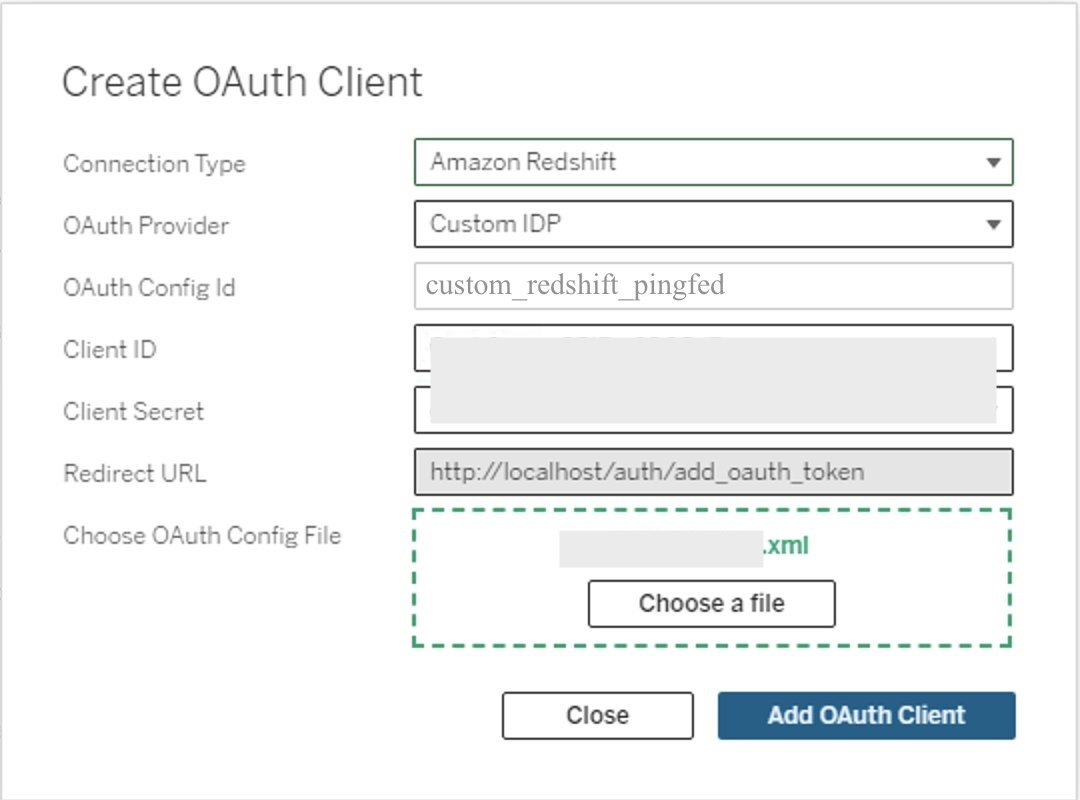
Figure 14: Create an OAuth connection in Tableau Server or Cloud

Federate to Amazon Redshift from Tableau Desktop using IAM Identity Center

Now, you’re ready to connect from Tableau and federated sign-in using IAM Identity Center authentication. In this step, you will create a Tableau Desktop report and publish it to Tableau Server.

  1. Open Tableau Desktop.
  2. Choose Amazon Redshift Connector and enter the following values:
    1. Server: Enter the name of the server that hosts the database and the name of the database you want to connect to.
    2. Port: Enter 5439.
    3. Database: Enter your database name. In this example, we use dev.
    4. Authentication: Select OAuth.
    5. Federation Type: Select Identity Center
    6. Identity Center Namespace: You can leave this blank.
    7. OAuth Provider: This value should automatically be pulled from your configured XML. It will be the value from the element oauthConfigId.
    8. Select checkbox for Require SSL.
  3. Choose Sign-In.
  4. A browser pop-up will initiate where you will enter your IdP credentials.

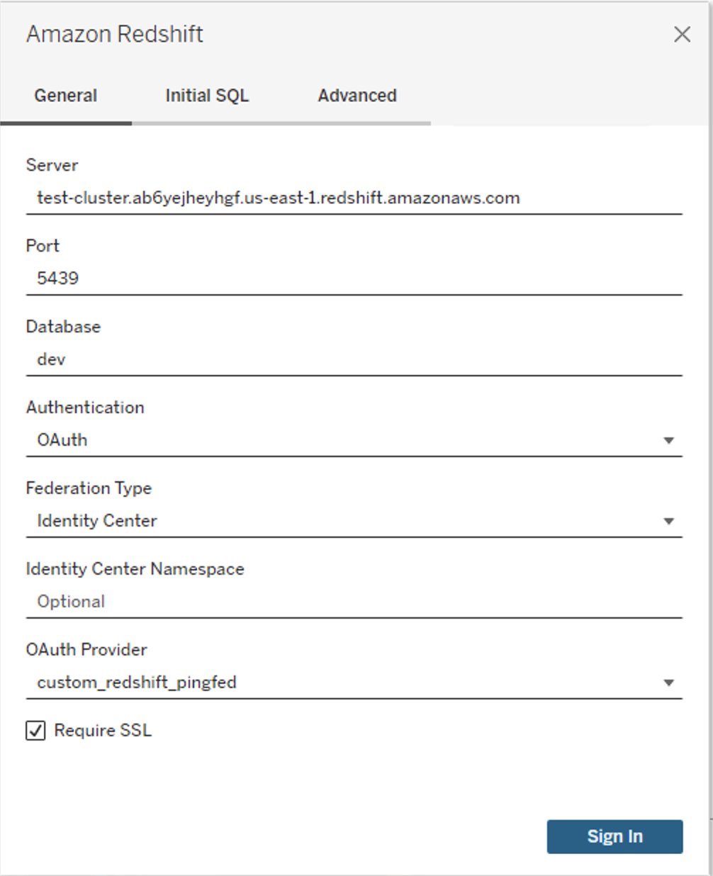
Figure 15: Tableau Desktop OAuth connection

  1. When authentication is successful, you will see the message Tableau created this window to authenticate. It is now safe to close it.

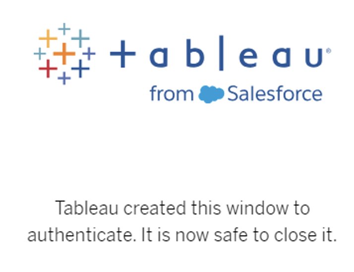
Figure 16: Successful authentication using Tableau

Congratulations! You are signed in using the IAM Identity Center integration with Amazon Redshift and are ready to explore and analyze your data using Tableau Desktop.

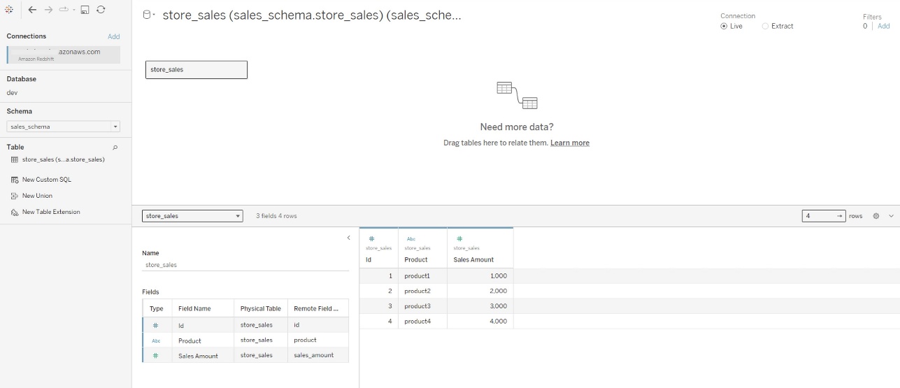
Figure 17: Successful connection using Tableau Desktop

The following is a screenshot from Amazon Redshift system table (sys_query_history) showing that user Ethan from PingFederate is accessing the sales report.

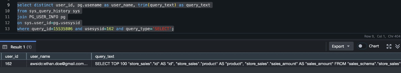
Figure 18: User audit in sys_query_history

Now you can create your own Tableau Report on the desktop version and publish it to your Tableau Server. For the next section, you create and publish a report named Account Level Sales.

Federate to Amazon Redshift from Tableau Server using IAM Identity Center authentication

After you have published the report from Tableau Desktop to Tableau Server, sign in as non-admin user and view the published report using IAM Identity Center authentication.

  1. Sign in to the Tableau Server site as a non-admin user.
  2. Navigate to Explore and go to the folder where your published report is stored.
  3. Select the report and choose Sign In.

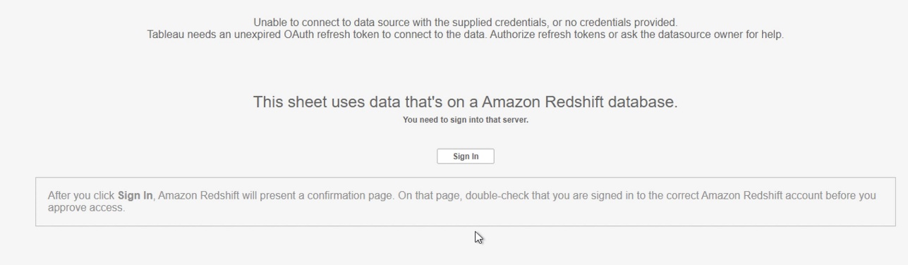
Figure 19: Sign In Prompt on Tableau Cloud/Server

  1. Enter your PingFederate credentials to the browser pop-up to authenticate.
  2. After successful authentication, you can access the data and create reports.

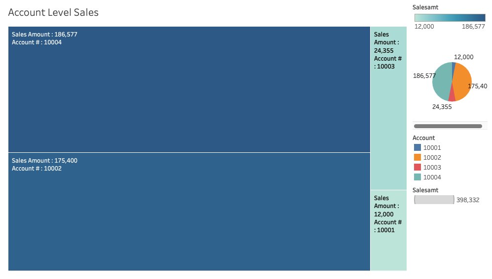
Figure 20: Tableau report

Clean up

Complete the following steps to clean up your resources:

  1. Delete the IdP applications that you created to integrate with IAM Identity Center.
  2. Delete Identity Center configuration.
  3. Delete the Amazon Redshift application and the Amazon Redshift provisioned cluster or Serverless instance that you created for testing.
  4. Delete the IAM role and IAM policy that you created for Identity Center and Amazon Redshift integration.
  5. Delete the permission set from Identity Center that you created for Amazon Redshift Query Editor v2 in the management account.
  6. Clean up resources related to PingFederate.

Conclusion

This post covered streamlining access management for data analytics by using Tableau’s capability to support single sign-on based on the OAuth 2.0 and OIDC protocol. This setup facilitates federated user authentication, where user identities from an external identity provider like PingFederate are trusted and propagated to Amazon Redshift. You walked through the steps to configure Tableau Desktop and Tableau Server to integrate seamlessly with Amazon Redshift using AWS IAM Identity Center for single sign-on. By harnessing this integration of a third-party IdP with IAM Identity Center, analysts can securely access Amazon Redshift data sources within Tableau without managing separate database credentials.

Learn more about Amazon Redshift integration with IAM Identity Center using PingFederate as an identity provider by visiting the following resources.


About the authors

Rohit Vashishtha

Rohit Vashishtha

Rohit is a Senior Analytics Specialist Solutions Architect at AWS based in Dallas, Texas. He has two decades of experience architecting, building, leading, and maintaining big data platforms. Rohit helps customers modernize their analytic workloads using the breadth of AWS services and ensures that customers get the best price/performance with utmost security and data governance.

Maneesh Sharma

Maneesh Sharma

Maneesh is a Database Modernization ProServ Consultant at AWS with 15 years of experience designing and implementing large-scale data warehouse and analytics solutions. He works closely with customers to help them modernize their legacy applications to AWS cloud-based platforms.

Jared Warren

Jared Warren

Jared is a Principal Solutions Architect at Amazon Web Services, working with our Enterprise customers. Outside of work, he plays board games (the nerdier the better) and smokes bar-b-que in his backyard.

Jason Veinot

Jason Veinot

Jason is a Senior Solutions Architect at Ping Identity with more than 20 years’ experience in IT and cybersecurity. He specializes in Identity and Access Management (IAM), pairing deep infrastructure and cloud expertise with hands-on leadership to design and deliver modern identity solutions. Jason partners with leading technology providers to accelerate outcomes and help organizations achieve their unique IAM goals.

Accelerate Amazon Redshift secure data use with Satori – Part 2

Post Syndicated from Rohit Vashishtha original https://aws.amazon.com/blogs/big-data/accelerate-amazon-redshift-secure-data-use-with-satori-part-2/

This post is co-written by Adam Gaulding, Solution Architect at Satori.

In this post, we continue from Accelerate Amazon Redshift secure data use with Satori – Part 1, and explain how Satori, an Amazon Redshift Ready partner, simplifies both the user experience of gaining access to data and the admin practice of granting and revoking access to data in Amazon Redshift. Satori enables both just-in-time and self-service access to data.

Solution overview

Satori creates a transparent layer providing visibility and control capabilities that is deployed in front of your existing Redshift data warehouse. When adding a new data store to Satori, a new, Satori-provided URL is generated for the data store, which data consumers use instead of connecting directly.

The following diagram illustrates the solution architecture.

Data consumers don’t have to change how they work with data, such as installing different database drivers, changing their queries, or compromising on features or functionality. Satori is not a data virtualization or database federation solution that abstracts your existing data stores.

Self-service access to data is fully automated. The admin is responsible for setting up the access rules. User access privileges can be preconfigured for automated dataset access. The user can see the datasets that are available to them in their personalized data portal. The user then selects the dataset they want to use and Satori automatically applies the appropriate security, privacy, and compliance requirements.

Just-in-time access to data is also flexible but requires approval from an admin. From the user’s personalized data portal, they can see the available datasets—the only datasets they have self-service access to are already included in their My Data folder. If they see a dataset that they need but don’t have access to, they can request access to this data on-demand. The request is sent to the admin and, based on the user’s credentials, the admin can choose to approve or deny access.

The ability to facilitate and automate access to data provides the following benefits:

  • Satori improves the user experience by providing quick access to data. This increases the time-to-value of data and drives innovative decision-making.
  • Admins benefit from automating the process, significantly reducing the amount of time spent on granting and revoking access to data.

Prerequisites

Follow the steps outlined in Accelerate Amazon Redshift secure data use with Satori – Part 1 to complete the following prerequisite steps:

  1. Prepare the data.
  2. Connect to Amazon Redshift.
  3. Create a dataset and give Satori control over access to the dataset.
  4. Optionally, create security policies and revisit the concepts related to secure data access and masking policies.

After you complete the prerequisites, you’re ready to explore self-service and just-in-time access to data.

Self-service access

The following steps explain how to create self-service rules from admin and user perspectives.

Create access request and self-service rules (admin perspective)

After the admin gives Satori control over access to the dataset, they need to first preconfigure the user access rules. Complete the following steps:

  1. Navigate to the Datasets page and choose User Access Requests.
  2. In the Self-Service Access section, choose Self-Service Rule.

  1. Specify the required level of access.

The admin has several options when configuring the access rules. You can set the level of access by user or group, define when it expires, and set revocation rules.

The following screenshot shows the configuration rule for data access requests we created. In this example, the self-service user group has read-only access during the next 30 days that is set to revoke within 7 days if it’s not used.

The following figure shows an example configuration rule to add a user.

The newly created access rule and details are displayed in the list of self-service rules.

The next steps outline the data user view and steps to gain self-service access to data.

Create access request and self-service rules (user perspective)

As a user, complete the following steps:

  1. Enter the Satori personalized data portal using the Data Portal option on the options menu (three vertical dots).

The data portal will display all available datasets. Any datasets that the user already has self-service access to will appear under My Data, as shown in the following screenshot. All other datasets appear under Available Datasets.

  1. Choose the desired dataset (in this case, CustomerDataset) and request immediate access to this dataset by choosing Ask for Access to Dataset.

  1. For Access Request, choose Self Service.
  2. For Request Message, enter a reason for the request.
  3. Choose Request.

Based on the user’s identity, preconfigured access rules match the user to their respective qualifications and authorizations. In this case, the user is automatically granted access to CustomerDataset using the preconfigured self-service rules. The requested dataset appears with Status – Access Granted under My Data.

The preconfigured access rules are applied so that when this user runs their queries, certain sensitive data is redacted.

Now that access is granted, query the data using a SQL editor of your choice. In this post, we use DBeaver to connect to a Redshift cluster using the Satori hostname on the data stores tab.

When you query the data, you will see the security policies applied to the result set at runtime. In the following example, the customer table is displayed with redacted field values based on security policies.

In the following example, the credit_cards table is displayed with masking policies applied to the result values.

Just-in-time access

Just-in-time access is similar to self-service access; the only difference is that it includes an additional step of requesting access from the admin.

Create access request and self-service rules (user perspective)

The user enters the Satori personalized data portal with the same view as shown in the self-service access to data.

If the data that you need isn’t included under My Data but shows under Available Datasets, you can request access to this dataset. For this example, we consider a new user John Doe trying to access CustomerDataset from the available datasets. The process consists of the following steps:

  1. User John Doe logs in to the Satori portal and finds the Available Datasets section in their data portal.
  2. The user submits a request for CustomerDataset.

The request from user John Doe for CustomerDataset stays in Pending Approval status until approved from the admin.

  1. The admin receives the request from user John Doe through email and portal notifications for dataset requests.

The admin can approve or deny the request and might also designate the level of access and when that access expires.

The following screenshot shows an example email notification.

  1. The admin can choose View Request in the email and then approve or deny the request on the Satori portal.

  1. The admin can choose the pencil icon to edit the request before approval and modify the approval conditions.

In this example, the admin modifies a couple of criteria as shown and then approves the request.

Create access request rules (admin perspective)

Users can request access to datasets and the admin can approve or reject those requests, but the admin can also preconfigure the user access rules. Complete the following steps as the admin:

  1. On the Datasets page, choose User Access Requests.
  2. Fill out the access request rule.
  3. Choose Add.

The access request rule creation will be treated as an approval workflow when dataset requests are placed from the data portal.

Dataset requests from users will follow the course of action configured by the admin during access request rules creation. The preconfigured access rules specific to that user are applied so that when this user runs their queries, security policies and masking conditions are applied, and sensitive data is redacted or masked as applicable. The access control is maintained according to the admin settings for both just-in-time access and self-service access.

Clean up

To avoid unintended costs, clean up the resources provisioned as part of Accelerate Amazon Redshift secure data use with Satori – Part 1 or provisioned for this post. Make sure to delete the following resources:

  • Redshift cluster or serverless endpoint
  • Security group to allow inbound traffic from Satori
  • Configurations within your Satori account

Summary

In this post, we described how Satori can help automate secure data access for both data users and admins. The ability to automate this process increases the time-to-value of data for users and reduces the time and resources admins need to allocate for granting and revoking data access.

Satori is available on the AWS Marketplace. To learn more, start a free trial or request a demo meeting.

Amazon Redshift provides comprehensive security and governance features to protect your data, and continues to expand its out-of-the-box capabilities. For the latest features and updates, explore Amazon Redshift What’s New.


About the Authors

Rohit Vashishtha is a Senior Analytics Specialist Solutions Architect at AWS based in Dallas, Texas. He has over 17 years of experience architecting, building, leading, and maintaining big data platforms. Rohit helps customers modernize their analytic workloads using the breadth of AWS services and ensures that customers get the best price/performance with utmost security and data governance.

Jagadish Kumar (Jag) is a Senior Specialist Solutions Architect at AWS focused on Amazon OpenSearch Service. He is deeply passionate about Data Architecture and helps customers build analytics solutions at scale on AWS.

 Adam Gaulding is a Solution Architect at Satori. At Satori, Adam is helping customers implement data security controls on databases, data lakes and data warehouses. Adam has been in and around the data space throughout his 20+ year career. He’s worked with companies large and small and prides himself in building creative solutions for technical problems.

Manage your workloads better using Amazon Redshift Workload Management

Post Syndicated from Rohit Vashishtha original https://aws.amazon.com/blogs/big-data/manage-your-workloads-better-using-amazon-redshift-workload-management/

With Amazon Redshift, you can run a complex mix of workloads on your data warehouse, such as frequent data loads running alongside business-critical dashboard queries and complex transformation jobs. We also see more and more data science and machine learning (ML) workloads. Each workload type has different resource needs and different service-level agreements (SLAs).

Amazon Redshift workload management (WLM) helps you maximize query throughput and get consistent performance for the most demanding analytics workloads by optimally using the resources of your existing data warehouse.

In Amazon Redshift, you implement WLM to define the number of query queues that are available and how queries are routed to those queues for processing. WLM queues are configured based on Redshift user groups, user roles, or query groups. When users belonging to a user group or role run queries in the database, their queries are routed to a queue as depicted in the following flowchart.

Role-based access control (RBAC) is a new enhancement that helps you simplify the management of security privileges in Amazon Redshift. You can use RBAC to control end-user access to data at a broad or granular level based on their job role. We have introduced support for Redshift roles in WLM queues, you will now find User roles along with User groups and Query groups as query routing mechanism.

This post provides examples of analytics workloads for an enterprise, and shares common challenges and ways to mitigate those challenges using WLM. We guide you through common WLM patterns and how they can be associated with your data warehouse configurations. We also show how to assign user roles to WLM queues and how to use WLM query insights to optimize configuration.

Use case overview

ExampleCorp is an enterprise using Amazon Redshift to modernize its data platform and analytics. They have variety of workloads with users from various departments and personas. The service-level performance requirements vary by the nature of the workload and user personas accessing the datasets. ExampleCorp would like to manage resources and priorities on Amazon Redshift using WLM queues. For this multitenant architecture by department, ExampleCorp can achieve read/write isolation using the Amazon Redshift data sharing feature and meet its unpredictable compute scaling requirements using concurrency scaling.

The following figure illustrates the user personas and access in ExampleCorp.

ExampleCorp has multiple Redshift clusters. For this post, we focus on the following:

  • Enterprise data warehouse (EDW) platform – This has all write workloads, along with some of the applications running reads via the Redshift Data API. The enterprise standardized data from the EDW cluster is accessed by multiple consumer clusters using the Redshift data sharing feature to run downstream reports, dashboards, and other analytics workloads.
  • Marketing data mart – This has predictable extract, transform, and load (ETL) and business intelligence (BI) workloads at specific times of day. The cluster admin understands the exact resource requirements by workload type.
  • Auditor data mart – This is only used for a few hours a day to run scheduled reports.

ExampleCorp would like to better manage their workloads using WLM.

Solution overview

As we discussed in the previous section, ExampleCorp has multiple Redshift data warehouses: one enterprise data warehouse and two downstream Redshift data warehouses. Each data warehouse has different workloads, SLAs, and concurrency requirements.

A database administrator (DBA) will implement appropriate WLM strategies on each Redshift data warehouse based on their use case. For this post, we use the following examples:

  • The enterprise data warehouse demonstrates Auto WLM with query priorities
  • The marketing data mart cluster demonstrates manual WLM
  • The auditors team uses their data mart infrequently for sporadic workloads; they use Amazon Redshift Serverless, which doesn’t require workload management

The following diagram illustrates the solution architecture.

Prerequisites

Before beginning this solution, you need the following:

  • An AWS account
  • Administrative access to Amazon Redshift

Let’s start by understanding some foundational concepts before solving the problem statement for ExampleCorp. First, how to choose between auto vs. manual WLM.

Auto vs. manual WLM

Amazon Redshift WLM enables you to flexibly manage priorities within workloads to meet your SLAs. Amazon Redshift supports Auto WLM or manual WLM for your provisioned Redshift data warehouse. The following diagram illustrates queues for each option.

Auto WLM determines the amount of resources that queries need and adjusts the concurrency based on the workload. When queries requiring large amounts of resources are in the system (for example, hash joins between large tables), the concurrency is lower. For additional information, refer to Implementing automatic WLM. You should use Auto WLM when your workload is highly unpredictable.

With manual WLM, you manage query concurrency and memory allocation, as opposed to auto WLM, where it’s managed by Amazon Redshift automatically. You configure separate WLM queues for different workloads like ETL, BI, and ad hoc and customize resource allocation. For additional information, refer to Tutorial: Configuring manual workload management (WLM) queues.

Use manual when When your workload pattern is predictable or if you need to throttle certain types of queries depending on the time of day, such as throttle down ingestion during business hours. If you need to guarantee multiple workloads are able to run at the same time, you can define slots for each workload.

Now that you have chosen automatic or manual WLM, let’s explore WLM parameters and properties.

Static vs. dynamic properties

The WLM configuration for a Redshift data warehouse is set using a parameter group under the database configuration properties.

The parameter group WLM settings are either dynamic or static. You can apply dynamic properties to the database without a cluster reboot, but static properties require a cluster reboot for changes to take effect. The following table summarizes the static vs. dynamic requirements for different WLM properties.

WLM Property Automatic WLM Manual WLM
Query groups Dynamic Static
Query group wildcard Dynamic Static
User groups Dynamic Static
User group wildcard Dynamic Static
User roles Dynamic Static
User role wildcard Dynamic Static
Concurrency on main Not applicable Dynamic
Concurrency Scaling mode Dynamic Dynamic
Enable short query acceleration Not applicable Dynamic
Maximum runtime for short queries Dynamic Dynamic
Percent of memory to use Not applicable Dynamic
Timeout Not applicable Dynamic
Priority Dynamic Not applicable
Adding or removing queues Dynamic Static

Note the following:

  • The parameter group parameters and WLM switch from manual to auto or vice versa and are static properties, and therefore require a cluster reboot.
  • For the WLM properties Concurrency on main, Percentage of memory to use, and Timeout, which are dynamic for manual WLM, the change only applies to new queries submitted after the value has changed and not for currently running queries.
  • The query monitoring rules, which we discuss later in this post, are dynamic and don’t require a cluster reboot.

In the next section, we discuss the concept of service class, meaning which queue does the query get submitted to and why.

Service class

Whether you use Auto or manual WLM, the user queries submitted go to the intended WLM queue via one of the following mechanisms:

  • User_Groups – The WLM queue directly maps to Redshift groups that would appear in the pg_group table.
  • Query_Groups – Queue assignment is based on the query_group label. For example, a dashboard submitted from the same reporting user can have separate priorities by designation or department.
  • User_Roles (latest addition) – The queue is assigned based on the Redshift roles.

WLM queues from a metadata perspective are defined as service class configuration. The following table lists common service class identifiers for your reference.

ID Service class
1–4 Reserved for system use.
5 Used by the superuser queue.
6–13 Used by manual WLM queues that are defined in the WLM configuration.
14 Used by short query acceleration.
15 Reserved for maintenance activities run by Amazon Redshift.
100–107 Used by automatic WLM queue when auto_wlm is true.

The WLM queues you define based on user_groups, query_groups, or user_roles fall in service class ID 6–13 for manual WLM and service class id 100–107 for automatic WLM.

Using Query_group, you can force a query to go to service class 5 and run in the superuser queue (provided you are an authorized superuser) as shown in the following code:

set query_group to 'superuser';
analyze table_xyz;
vacuum full table_xyz;
reset query_group;

For more details on how to assign a query to a particular service class, refer to Assigning queries to queues.

The short query acceleration (SQA) queue (service class 14) prioritizes short-running queries ahead of longer-running queries. If you enable SQA, you can reduce WLM queues that are dedicated to running short queries. In addition, long-running queries don’t need to contend with short queries for slots in a queue, so you can configure your WLM queues to use fewer query slots (a term used for available concurrency). Amazon Redshift uses an ML algorithm to analyze each eligible query and predict the query’s runtime. Auto WLM dynamically assigns a value for the SQA maximum runtime based on analysis of your cluster’s workload. Alternatively, you can specify a fixed value of 1–20 seconds when using manual WLM.

SQA is enabled by default in the default parameter group and for all new parameter groups. SQA can have a maximum concurrency of six queries.

Now that you understand how queries get submitted to a service class, it’s important to understand ways to avoid runaway queries and initiate an action for an unintended event.

Query monitoring rules

You can use Amazon Redshift query monitoring rules (QMRs) to set metrics-based performance boundaries for WLM queues and specify what action to take when a query goes beyond those boundaries.

The Redshift cluster automatically collects query monitoring metrics. You can query the system view SVL_QUERY_METRICS_SUMMARY as an aid to determine threshold values for defining the QMR. Then create the QMR based on following attributes:

  • Query runtime, in seconds
  • Query return row count
  • The CPU time for a SQL statement

For a complete list of QMRs, refer to WLM query monitoring rules.

Create sample parameter groups

For our ExampleCorp use case, we demonstrate automatic and manual WLM for a provisioned Redshift data warehouse and share a serverless perspective of WLM.

The following AWS CloudFormation template provides an automated way to create sample parameter groups that you can attach to your Redshift data warehouse for workload management.

Enterprise data warehouse Redshift cluster using automatic WLM

For the EDW cluster, we use Auto WLM. To configure the service class, we look at all three options: user_roles, user_groups, and query_groups.

Here’s a glimpse of how this can be set up in WLM queues and then used in your queries.

On the Amazon Redshift console, under Configurations in the navigation pane, choose Workload Management. You can create a new parameter group or modify an existing one created by you. Select the parameter group to edit its queues. There’s always a default queue (the last one in case of multiple queues defined), which is a catch-all for queries that don’t get routed to any specific queue.

User roles in WLM

With the introduction of user roles in WLM queues, now you can manage your workload by adding different roles to different queues. This can help you prioritize the queries based on the roles a user has. When a user runs a query, WLM will check if this user’s roles were added in any workload queues and assign the query to the first matching queue. To add roles into the WLM queue, you can go to the WLM page, create or modify an existing workload queue, add a user’s roles in the queue, and select Matching wildcards to add roles that get matched as wildcards.

For more information about how to convert from groups to roles, refer to Amazon Redshift Roles (RBAC), which walks you through a stored procedure to convert groups to roles.

In the following example, we have created the WLM queue EDW_Admins, which uses edw_admin_role created in Amazon Redshift to submit the workloads in this queue. The EDW_Admins queue is created with a high priority and automatic concurrency scaling mode.

User groups

Groups are collections of users who are all granted permissions associated with the group. You can use groups to simplify permission management by granting privileges just one time. If the members of a group get added or removed, you don’t need to manage them at a user level. For example, you can create different groups for sales, administration, and support and give the users in each group the appropriate access to the data they need for their work.

You can grant or revoke permissions at the user group level, and those changes will apply to all members of the group.

ETL, data analysts, or BI or decision support systems can use user groups to better manage and isolate their workloads. For our example, ETL WLM queue queries will be run with the user group etl. The data analyst group (BI) WLM queue queries will run using the bi user group.

Choose Add queue to add a new queue that you will use for user_groups, in this case ETL. If you would like these to be matched as wildcards (strings containing those keywords), select Matching wildcards. You can customize other options like query priority and concurrency scaling, explained earlier in this post. Choose Save to complete this queue setup.

In the following example, we have created two different WLM queues for ETL and BI. The ETL queue has a high priority and concurrency scaling mode is off, whereas the BI queue has a low priority and concurrency scaling mode is off.

Use the following code to create a group with multiple users:

-- Example of create group with multiple users
create group ETL with user etl_user1, etl_user2;
Create group BI with user bi_user1, bi_user2;

Query groups

Query_Groups are labels used for queries that are run within the same session. Think of these as tags that you may want to use to identify queries for a uniquely identifiable use case. In our example use case, the data analysts or BI or decision support systems can use query_groups to better manage and isolate their workloads. For our example, weekly business reports can run with the query_group label wbr. Queries from the marketing department can be run with a query_group of marketing.

The benefit of using query_groups is that you can use it to constrain results from the STL_QUERY and STV_INFLIGHT tables and the SVL_QLOG view. You can apply a separate label to every query that you run to uniquely identify queries without having to look up their IDs.

Choose Add queue to add a new queue that you will use for query_groups, in this case wbr or weekly_business_report. If you would like these to be matched as wildcards (strings containing those keywords), select Matching wildcards. You can customize other options like query priority and concurrency scaling options as explained earlier in this post. Choose Save to save this queue setup.

Now let’s see how you can force a query to use the query_groups queue just created.

You can assign a query to a queue at runtime by assigning your query to the appropriate query group. Use the SET command to begin a query group:

SET query_group TO wbr;
-- or
SET query_group TO weekly_business_report;

Queries following the SET command would go to the WLM queue Query_Group_WBR until you either reset the query group or end your current login session. For information about setting and resetting server configuration parameter, see SET and RESET, respectively.

The query group labels that you specify must be included in the current WLM configuration; otherwise, the SET query_group command has no effect on query queues.

For more query_groups examples, refer to WLM queue assignment rules.

Marketing Redshift cluster using manual WLM

Expanding on the marketing Redshift cluster use case of ExampleCorp, this cluster serves two types of workloads:

  • Running ETL for a period of 2 hours between 7:00 AM to 9:00 AM
  • Running BI reports and dashboards for the remaining time during the day

When you have such a clarity in the workloads, and your scope of usage is customizable by design, you may want to consider using manual WLM, where you can control the memory and concurrency resource allocation. Auto WLM will still be applicable, but manual WLM can also be a choice.

Let’s set up manual WLM in this case, with two WLM queues: ETL and BI.

To best utilize the resources, we use an AWS Command Line Interface (AWS CLI) command at the start of our ETL, which will make our WLM queues ETL-friendly, providing higher concurrency to the ETL queue. At the end of our ETL, we use an AWS CLI command to change the WLM queue to have BI-friendly resource settings. Modifying the WLM queues doesn’t require a reboot of your cluster; however, modifying the parameters or parameter group does.

If you were to use Auto WLM, this could have been achieved by dynamically changing the query priority of the ETL and BI queues.

By default, when you choose Create, the WLM created will be Auto WLM. You can switch to manual WLM by choosing Switch WLM mode. After switching WLM mode, choose Edit workload queues.

This will open the Modify workload queues page, where you can create your ETL and BI WLM queues.

After you add your ETL and BI queues, choose Save. You should have configured the following:

  • An ETL queue with 60% memory allocation and query concurrency of 9
  • A BI queue with 30% memory allocation and query concurrency of 4
  • A default queue with 10% memory allocation and query concurrency of 2

Your WLM queues should appear with settings as shown in the following screenshot.

Enterprises may prefer to complete these steps in an automated way. For the marketing data mart use case, the ETL starts at 7:00 AM. An ideal start to the ETL flow would be to have a job that makes your WLM settings ETL queue friendly. Here’s how you would modify concurrency and memory (both dynamic properties in manual WLM queues) to an ETL-friendly configuration:

aws redshift --region 'us-east-1' modify-cluster-parameter-group --parameter-group-name manual-wlm-demo --parameters '{"ParameterName": "wlm_json_configuration","ParameterValue": "[{\"query_group\": [], \"user_group\": [\"etl\"],\"query_group_wild_card\": 0,\"user_group_wild_card\": 0, \"query_concurrency\": 9, \"max_execution_time\": 0, \"memory_percent_to_use\": 60, \"name\": \"ETL\" }, {\"query_group\": [], \"user_group\": [\"bi\"],\"query_group_wild_card\": 0,\"user_group_wild_card\": 0, \"query_concurrency\": 3, \"max_execution_time\": 0, \"memory_percent_to_use\": 20, \"name\": \"BI\" }, { \"query_group\": [], \"user_group\": [], \"query_group_wild_card\": 0, \"user_group_wild_card\": 0, \"query_concurrency\": 3, \"max_execution_time\": 5400000, \"memory_percent_to_use\": 20, \"name\": \"Default queue\", \"rules\": [ { \"rule_name\": \"user_query_duration_threshold\", \"predicate\": [ { \"metric_name\": \"query_execution_time\", \"operator\": \">\", \"value\": 10800 } ], \"action\": \"abort\" } ] }, { \"short_query_queue\": \"true\" } ]","Description": "ETL Start, ETL Friendly"}';

The preceding AWS CLI command programmatically sets the configuration of your WLM queues without requiring a reboot of the cluster because the queue settings changed were all dynamic settings.

For the marketing data mart use case, at 9:00 AM or when the ETL is finished, you can have a job run an AWS CLI command to modify the WLM queue resource settings to a BI-friendly configuration as shown in the following code:

aws redshift --region 'us-east-1' modify-cluster-parameter-group --parameter-group-name manual-wlm-demo --parameters '{"ParameterName": "wlm_json_configuration","ParameterValue": "[{\"query_group\": [], \"user_group\": [\"etl\"],\"query_group_wild_card\": 0,\"user_group_wild_card\": 0, \"query_concurrency\": 1, \"max_execution_time\": 0, \"memory_percent_to_use\": 5, \"name\": \"ETL\" }, {\"query_group\": [], \"user_group\": [\"bi\"],\"query_group_wild_card\": 0,\"user_group_wild_card\": 0, \"query_concurrency\": 12, \"max_execution_time\": 0, \"memory_percent_to_use\": 80, \"name\": \"BI\" }, { \"query_group\": [], \"user_group\": [], \"query_group_wild_card\": 0, \"user_group_wild_card\": 0, \"query_concurrency\": 2, \"max_execution_time\": 5400000, \"memory_percent_to_use\": 15, \"name\": \"Default queue\", \"rules\": [ { \"rule_name\": \"user_query_duration_threshold\", \"predicate\": [ { \"metric_name\": \"query_execution_time\", \"operator\": \">\", \"value\": 10800 } ], \"action\": \"abort\" } ] }, { \"short_query_queue\": \"true\" } ]","Description": "ETL End, BI Friendly"}';

Note that in regards to a manual WLM configuration, the maximum slots you can allocate to a queue is 50. However, this doesn’t mean that in an automatic WLM configuration, a Redshift cluster always runs 50 queries concurrently. This can change based on the memory needs or other types of resource allocation on the cluster. We recommend configuring your manual WLM query queues with a total of 15 or fewer query slots. For more information, see Concurrency level.

In case of WLM timeout or a QMR hop action within manual WLM, a query can attempt to hop to the next matching queue based on WLM queue assignment rules. This action in manual WLM is called query queue hopping.

Auditor Redshift data warehouse using WLM in Redshift Serverless

The auditor data warehouse workload runs on the month, and quarter end. For this periodic workload, Redshift Serverless is well suited, both from a cost and ease of administration perspective. Redshift Serverless uses ML to learn from your workload to automatically manage workload and auto scaling of compute needed for your workload.

In Redshift Serverless, you can set up usage and query limits. The query limits let you set up the QMR. You can choose Manage query limits to automatically trigger the default abort action when queries go beyond performance boundaries. For more information, refer to Query monitoring metrics for Amazon Redshift Serverless.

For other detailed limits in Redshift Serverless, refer to Configure monitoring, limits, and alarms in Amazon Redshift Serverless to keep costs predictable.

Monitor using system views for operational metrics

The system views in Amazon Redshift are used to monitor the workload performance. You can view the status of queries, queues, and service classes by using WLM-specific system tables. You can query system tables to explore the following details:

  • View which queries are being tracked and what resources are allocated by the workload manager
  • See which queue a query has been assigned to
  • View the status of a query that is currently being tracked by the workload manager

You can download the sample SQL notebook system queries. You can import this in Query Editor V2.0. The queries in the sample notebook can help you explore your workloads being managed by WLM queues.

Conclusion

In this post, we covered real-world examples for Auto WLM and manual WLM patterns. We introduced user roles assignment to WLM queues, and shared queries on system views and tables to gather operational insights on your WLM configuration. We encourage you to explore using Redshift user roles with workload management. Use the script provided on AWS re:Post to convert groups to roles, and start using user roles for your WLM queues.


About the Authors

Rohit Vashishtha is a Senior Analytics Specialist Solutions Architect at AWS based in Dallas, Texas. He has over 17 years of experience architecting, building, leading, and maintaining big data platforms. Rohit helps customers modernize their analytic workloads using the breadth of AWS services and ensures that customers get the best price/performance with utmost security and data governance.

Harshida Patel is a Principal specialist SA with AWS.

Nita Shah is an Analytics Specialist Solutions Architect at AWS based out of New York. She has been building data warehouse solutions for over 20 years and specializes in Amazon Redshift. She is focused on helping customers design and build enterprise-scale well-architected analytics and decision support platforms.

Yanzhu Ji is a Product Manager in the Amazon Redshift team. She has experience in product vision and strategy in industry-leading data products and platforms. She has outstanding skill in building substantial software products using web development, system design, database, and distributed programming techniques. In her personal life, Yanzhu likes painting, photography, and playing tennis.

Getting started guide for near-real time operational analytics using Amazon Aurora zero-ETL integration with Amazon Redshift

Post Syndicated from Rohit Vashishtha original https://aws.amazon.com/blogs/big-data/getting-started-guide-for-near-real-time-operational-analytics-using-amazon-aurora-zero-etl-integration-with-amazon-redshift/

Amazon Aurora zero-ETL integration with Amazon Redshift was announced at AWS re:Invent 2022 and is now available in public preview for Amazon Aurora MySQL-Compatible Edition 3 (compatible with MySQL 8.0) in regions us-east-1, us-east-2, us-west-2, ap-northeast-1 and eu-west-1. For more details, refer to the What’s New Post.

In this post, we provide step-by-step guidance on how to get started with near-real time operational analytics using this feature.

Challenges

Customers across industries today are looking to increase revenue and customer engagement by implementing near-real time analytics use cases like personalization strategies, fraud detection, inventory monitoring, and many more. There are two broad approaches to analyzing operational data for these use cases:

  • Analyze the data in-place in the operational database (e.g. read replicas, federated query, analytics accelerators)
  • Move the data to a data store optimized for running analytical queries such as a data warehouse

The zero-ETL integration is focused on simplifying the latter approach.

A common pattern for moving data from an operational database to an analytics data warehouse is via extract, transform, and load (ETL), a process of combining data from multiple sources into a large, central repository (data warehouse). ETL pipelines can be expensive to build and complex to manage. With multiple touchpoints, intermittent errors in ETL pipelines can lead to long delays, leaving applications that rely on this data to be available in the data warehouse with stale or missing data, further leading to missed business opportunities.

For customers that need to run unified analytics across data from multiple operational databases, solutions that analyze data in-place may work great for accelerating queries on a single database, but such systems have a limitation of not being able to aggregate data from multiple operational databases.

Zero-ETL

At AWS, we have been making steady progress towards bringing our zero-ETL vision to life. With Aurora zero-ETL integration with Amazon Redshift, you can bring together the transactional data of Aurora with the analytics capabilities of Amazon Redshift. It minimizes the work of building and managing custom ETL pipelines between Aurora and Amazon Redshift. Data engineers can now replicate data from multiple Aurora database clusters into the same or a new Amazon Redshift instance to derive holistic insights across many applications or partitions. Updates in Aurora are automatically and continuously propagated to Amazon Redshift so the data engineers have the most recent information in near-real time. Additionally, the entire system can be serverless and can dynamically scale up and down based on data volume, so there’s no infrastructure to manage.

When you create an Aurora zero-ETL integration with Amazon Redshift, you continue to pay for Aurora and Amazon Redshift usage with existing pricing (including data transfer). The Aurora zero-ETL integration with Amazon Redshift feature is available at no additional cost.

With Aurora zero-ETL integration with Amazon Redshift, the integration replicates data from the source database into the target data warehouse. The data becomes available in Amazon Redshift within seconds, allowing users to use the analytics features of Amazon Redshift and capabilities like data sharing, workload optimization autonomics, concurrency scaling, machine learning, and many more. You can perform real-time transaction processing on data in Aurora while simultaneously using Amazon Redshift for analytics workloads such as reporting and dashboards.

The following diagram illustrates this architecture.

Solution overview

Let’s consider TICKIT, a fictional website where users buy and sell tickets online for sporting events, shows, and concerts. The transactional data from this website is loaded into an Aurora MySQL 3.03.1 (or higher version) database. The company’s business analysts want to generate metrics to identify ticket movement over time, success rates for sellers, and the best-selling events, venues, and seasons. They would like to get these metrics in near-real time using a zero-ETL integration.

The integration is set up between Amazon Aurora MySQL-Compatible Edition 3.03.1 (source) and Amazon Redshift (destination). The transactional data from the source gets refreshed in near-real time on the destination, which processes analytical queries.

You can use either the provisioned or serverless option for both Amazon Aurora MySQL-Compatible Edition as well as Amazon Redshift. For this illustration, we use a provisioned Aurora database and an Amazon Redshift Serverless data warehouse. For the complete list of public preview considerations, please refer to the feature AWS documentation.

The following diagram illustrates the high-level architecture.

The following are the steps needed to set up zero-ETL integration. For complete getting started guides, refer to the following documentation links for Aurora and Amazon Redshift.

  1. Configure the Aurora MySQL source with a customized DB cluster parameter group.
  2. Configure the Amazon Redshift Serverless destination with the required resource policy for its namespace.
  3. Update the Redshift Serverless workgroup to enable case-sensitive identifiers.
  4. Configure the required permissions.
  5. Create the zero-ETL integration.
  6. Create a database from the integration in Amazon Redshift.

Configure the Aurora MySQL source with a customized DB cluster parameter group

To create an Aurora MySQL database, complete the following steps:

  1. On the Amazon RDS console, create a DB cluster parameter group called zero-etl-custom-pg.

Zero-ETL integrations require specific values for the Aurora DB cluster parameters that control binary logging (binlog). For example, enhanced binlog mode must be turned on (aurora_enhanced_binlog=1).

  1. Set the following binlog cluster parameter settings:
    1. binlog_backup=0
    2. binlog_replication_globaldb=0
    3. binlog_format=ROW
    4. aurora_enhanced_binlog=1
    5. binlog_row_metadata=FULL
    6. binlog_row_image=FULL
  2. Choose Save changes.
  3. Choose Databases in the navigation pane, then choose Create database.
  4. For Available versions, choose Aurora MySQL 3.03.1 (or higher).
  5. For Templates, select Production.
  6. For DB cluster identifier, enter zero-etl-source-ams.
  7. Under Instance configuration, select Memory optimized classes and choose a suitable instance size (the default is db.r6g.2xlarge).
  8. Under Additional configuration, for DB cluster parameter group, choose the parameter group you created earlier (zero-etl-custom-pg).
  9. Choose Create database.

In a couple of minutes, it should spin up an Aurora MySQL database as the source for zero-ETL integration.

Configure the Redshift Serverless destination

For our use case, create a Redshift Serverless data warehouse by completing the following steps:

  1. On the Amazon Redshift console, choose Serverless dashboard in the navigation pane.
  2. Choose Create preview workgroup.
  3. For Workgroup name, enter zero-etl-target-rs-wg.
  4. For Namespace, select Create a new namespace and enter zero-etl-target-rs-ns.
  5. Navigate to the namespace zero-etl-target-rs-ns and choose the Resource policy tab.
  6. Choose Add authorized principals.
  7. Enter either the Amazon Resource Name (ARN) of the AWS user or role, or the AWS account ID (IAM principals) that are allowed to create integrations in this namespace.

An account ID is stored as an ARN with root user.

  1. Add an authorized integration source to the namespace and specify the ARN of the Aurora MySQL DB cluster that’s the data source for the zero-ETL integration.
  2. Choose Save changes.

You can get the ARN for the Aurora MySQL source on the Configuration tab as shown in the following screenshot.

Update the Redshift Serverless workgroup to enable case-sensitive identifiers

Use the AWS Command Line Interface (AWS CLI) to run the update-workgroup action:

aws redshift-serverless update-workgroup --workgroup-name zero-etl-target-rs-wg --config-parameters parameterKey=enable_case_sensitive_identifier,parameterValue=true --region us-east-1

You can use AWS CloudShell or another interface like Amazon Elastic Compute Cloud (Amazon EC2) with an AWS user configuration that can update the Redshift Serverless parameter group. The following screenshot illustrates how to run this on CloudShell.

The following screenshot shows how to run the update-workgroup command on Amazon EC2.

Configure required permissions

To create a zero-ETL integration, your user or role must have an attached identity-based policy with the appropriate AWS Identity and Access Management (IAM) permissions. The following sample policy allows the associated principal to perform the following actions:

  • Create zero-ETL integrations for the source Aurora DB cluster.
  • View and delete all zero-ETL integrations.
  • Create inbound integrations into the target data warehouse. This permission is not required if the same account owns the Amazon Redshift data warehouse and this account is an authorized principal for that data warehouse. Also note that Amazon Redshift has a different ARN format for provisioned and serverless:
    • Provisioned clusterarn:aws:redshift:{region}:{account-id}:namespace:namespace-uuid
    • Serverlessarn:aws:redshift-serverless:{region}:{account-id}:namespace/namespace-uuid

Complete the following steps to configure the permissions:

  1. On the IAM console, choose Policies in the navigation pane.
  2. Choose Create policy.
  3. Create a new policy called rds-integrations using the following JSON:
    {
        "Version": "2012-10-17",
        "Statement": [{
            "Effect": "Allow",
            "Action": [
                "rds:CreateIntegration"
            ],
            "Resource": [
                "arn:aws:rds:{region}:{account-id}:cluster:source-cluster",
                "arn:aws:rds:{region}:{account-id}:integration:*"
            ]
        },
        {
            "Effect": "Allow",
            "Action": [
                "rds:DescribeIntegration"
            ],
            "Resource": ["*"]
        },
        {
            "Effect": "Allow",
            "Action": [
                "rds:DeleteIntegration"
            ],
            "Resource": [
                "arn:aws:rds:{region}:{account-id}:integration:*"
            ]
        },
        {
            "Effect": "Allow",
            "Action": [
                "redshift:CreateInboundIntegration"
            ],
            "Resource": [
                "arn:aws:redshift:{region}:{account-id}:cluster:namespace-uuid"
            ]
        }]
    }

Policy preview:

If you see IAM policy warnings for the RDS policy actions, this is expected because the feature is in public preview. These actions will become part of IAM policies when the feature is generally available. It’s safe to proceed.

  1. Attach the policy you created to your IAM user or role permissions.

Create the zero-ETL integration

To create the zero-ETL integration, complete the following steps:

  1. On the Amazon RDS console, choose Zero-ETL integrations in the navigation pane.
  2. Choose Create zero-ETL integration.
  3. For Integration name, enter a name, for example zero-etl-demo.
  4. For Aurora MySQL source cluster, browse and choose the source cluster zero-etl-source-ams.
  5. Under Destination, for Amazon Redshift data warehouse, choose the Redshift Serverless destination namespace (zero-etl-target-rs-ns).
  6. Choose Create zero-ETL integration.

To specify a target Amazon Redshift data warehouse that’s in another AWS account, you must create a role that allows users in the current account to access resources in the target account. For more information, refer to Providing access to an IAM user in another AWS account that you own.

Create a role in the target account with the following permissions:

{
   "Version":"2012-10-17",
   "Statement":[
      {
         "Effect":"Allow",
         "Action":[
            "redshift:DescribeClusters",
            "redshift-serverless:ListNamespaces"
         ],
         "Resource":[
            "*"
         ]
      }
   ]
}

The role must have the following trust policy, which specifies the target account ID. You can do this by creating a role with a trusted entity as an AWS account ID in another account.

{
   "Version":"2012-10-17",
   "Statement":[
      {
         "Effect":"Allow",
         "Principal":{
            "AWS": "arn:aws:iam::{external-account-id}:root"
         },
         "Action":"sts:AssumeRole"
      }
   ]
}

The following screenshot illustrates creating this on the IAM console.

Then while creating the zero-ETL integration, choose the destination account ID and the name of the role you created to proceed further, for Specify a different account option.

You can choose the integration to view the details and monitor its progress. It takes a few minutes to change the status from Creating to Active. The time varies depending on size of the dataset already available in the source.

Create a database from the integration in Amazon Redshift

To create your database, complete the following steps:

  1. On the Redshift Serverless dashboard, navigate to the zero-etl-target-rs-ns namespace.
  2. Choose Query data to open Query Editor v2.
  3. Connect to the preview Redshift Serverless data warehouse by choosing Create connection.
  4. Obtain the integration_id from the svv_integration system table:

    select integration_id from svv_integration; ---- copy this result, use in the next sql

  5. Use the integration_id from the previous step to create a new database from the integration:
    CREATE DATABASE aurora_zeroetl FROM INTEGRATION '<result from above>';

The integration is now complete, and an entire snapshot of the source will reflect as is in the destination. Ongoing changes will be synced in near-real time.

Analyze the near-real time transactional data

Now we can run analytics on TICKIT’s operational data.

Populate the source TICKIT data

To populate the source data, complete the following steps:

  1. Connect to your Aurora MySQL cluster and create a database/schema for the TICKIT data model, verify that the tables in that schema have a primary key, and initiate the load process:
    mysql -h <amazon_aurora_mysql_writer_endpoint> -u admin -p

You can use the script from the following HTML file to create the sample database demodb (using the tickit.db model) in Amazon Aurora MySQL-Compatible edition.

  1. Run the script to create the tickit.db model tables in the demodb database/schema:
  2. Load data from Amazon Simple Storage Service (Amazon S3), record the finish time for change data capture (CDC) validations at destination, and observe how active the integration was.

The following are common errors associated with load from Amazon S3:

  • For the current version of the Aurora MySQL cluster, we need to set the aws_default_s3_role parameter in the DB cluster parameter group to the role ARN that has the necessary Amazon S3 access permissions.
  • If you get an error for missing credentials (for example, Error 63985 (HY000): S3 API returned error: Missing Credentials: Cannot instantiate S3 Client), you probably haven’t associated your IAM role to the cluster. In this case, add the intended IAM role to the source Aurora MySQL cluster.

Analyze the source TICKIT data in the destination

On the Redshift Serverless dashboard, open Query Editor v2 using the database you created as part of the integration setup. Use the following code to validate the seed or CDC activity:

SELECT * FROM SYS_INTEGRATION_ACTIVITY;

Choose the cluster or workgroup and database created from integration on the drop-down menu and run tickit.db sample analytic queries.

Monitoring

You can query the following system views and tables in Amazon Redshift to get information about your Aurora zero-ETL integrations with Amazon Redshift:

In order to view the integration-related metrics published to Amazon CloudWatch, navigate to Amazon Redshift console. Choose Zero-ETL integrations from left navigation pane and click on the integration links to display activity metrics.

Available metrics on the Redshift console are Integration metrics and table statistics, with table statistics providing details of each table replicated from Aurora MySQL to Amazon Redshift.

Integration metrics contains table replication success/failure counts and lag details:

Clean up

When you delete a zero-ETL integration, Aurora removes it from your Aurora cluster. Your transactional data isn’t deleted from Aurora or Amazon Redshift, but Aurora doesn’t send new data to Amazon Redshift.

To delete a zero-ETL integration, complete the following steps:

  1. On the Amazon RDS console, choose Zero-ETL integrations in the navigation pane.
  2. Select the zero-ETL integration that you want to delete and choose Delete.
  3. To confirm the deletion, choose Delete.

Conclusion

In this post, we showed you how to set up Aurora zero-ETL integration from Amazon Aurora MySQL-Compatible Edition to Amazon Redshift. This minimizes the need to maintain complex data pipelines and enables near-real time analytics on transactional and operational data.

To learn more about Aurora zero-ETL integration with Amazon Redshift, visit documentation for Aurora and Amazon Redshift.


About the Authors

Rohit Vashishtha is a Senior Analytics Specialist Solutions Architect at AWS based in Dallas, Texas. He has 17 years of experience architecting, building, leading, and maintaining big data platforms. Rohit helps customers modernize their analytic workloads using the breadth of AWS services and ensures that customers get the best price/performance with utmost security and data governance.

Vijay Karumajji is a Database Solutions Architect with Amazon Web Services. He works with AWS customers to provide guidance and technical assistance on database projects, helping them improve the value of their solutions when using AWS.

BP Yau is a Sr Partner Solutions Architect at AWS. He is passionate about helping customers architect big data solutions to process data at scale. Before AWS, he helped Amazon.com Supply Chain Optimization Technologies migrate its Oracle data warehouse to Amazon Redshift and build its next generation big data analytics platform using AWS technologies.

Jyoti Aggarwal is a Product Manager on the Amazon Redshift team based in Seattle. She has spent the last 10 years working on multiple products in the data warehouse industry.

Adam Levin is a Product Manager on the Amazon Aurora team based in California. He has spent the last 10 years working on various cloud database services.

How dynamic data masking support in Amazon Redshift helps achieve data privacy and compliance

Post Syndicated from Rohit Vashishtha original https://aws.amazon.com/blogs/big-data/how-dynamic-data-masking-support-in-amazon-redshift-helps-achieve-data-privacy-and-compliance/

Amazon Redshift is a fully managed, petabyte-scale, massively parallel data warehouse that offers simple operations and high performance. It makes it fast, simple, and cost-effective to analyze all your data using standard SQL and your existing business intelligence (BI) tools. Today, Amazon Redshift is the most widely used cloud data warehouse.

Dynamic data masking (DDM) support (preview) in Amazon Redshift enables you to simplify the process of protecting sensitive data in your Amazon Redshift data warehouse. You can now use DDM to protect data based on your job role or permission rights and level of data sensitivity through a SQL interface. DDM support (preview) in Amazon Redshift enables you to hide, obfuscate, or pseudonymize column values within the tables in your data warehouse without incurring additional storage costs. It is configurable to allow you to define consistent, format-preserving, and irreversible masked data values.

DDM support (preview) in Amazon Redshift provides a native feature to support your need to mask data for regulatory or compliance requirements, or to increase internal privacy standards. Compared to static data masking where underlying data at rest gets permanently replaced or redacted, DDM support (preview) in Amazon Redshift enables you to temporarily manipulate the display of sensitive data in transit at query time based on user privilege, leaving the original data at rest intact. You control access to data through masking policies that apply custom obfuscation rules to a given user or role. That way, you can respond to changing privacy requirements without altering the underlying data or editing SQL queries.

With DDM support (preview) in Amazon Redshift, you can do the following:

  • Define masking policies that apply custom obfuscation policies (for example, masking policies to handle credit card, PII entries, HIPAA or GDPR needs, and more)
  • Transform the data at query time to apply masking policies
  • Attach masking policies to roles or users
  • Attach multiple masking policies with varying levels of obfuscation to the same column in a table and assign them to different roles with priorities to avoid conflicts
  • Implement cell-level masking by using conditional columns when creating your masking policy
  • Use masking policies to partially or completely redact data, or hash it by using user-defined functions (UDFs)

Here’s what our customers have to say on DDM support(private beta) in Amazon Redshift:

“Baffle delivers data-centric protection for enterprises via a data security platform that is transparent to applications and unique to data security. Our mission is to seamlessly weave data security into every data pipeline. Previously, to apply data masking to an Amazon Redshift data source, we had to stage the data in an Amazon S3 bucket. Now, by utilizing the Amazon Redshift Dynamic Data Masking capability, our customers can protect sensitive data throughout the analytics pipeline, from secure ingestion to responsible consumption reducing the risk of breaches.”

-Ameesh Divatia, CEO & co-founder of Baffle

“EnergyAustralia is a leading Australian energy retailer and generator, with a mission to lead the clean energy transition for customers in a way that is reliable, affordable and sustainable for all. We enable all corners of our business with Data & Analytics capabilities that are used to optimize business processes and enhance our customers’ experience. Keeping our customers’ data safe is a top priority across our teams. In the past, this involved multiple layers of custom built security policies that could make it cumbersome for analysts to find the data they require. The new AWS dynamic data masking feature will significantly simplify our security processes so we continue to keep customer data safe, while also reducing the administrative overhead.”

-William Robson, Data Solutions Design Lead, EnergyAustralia

Use case

For our use case, a retail company wants to control how they show credit card numbers to users based on their privilege. They also don’t want to duplicate the data for this purpose. They have the following requirements:

  • Users from Customer Service should be able to view the first six digits and the last four digits of the credit card for customer verification
  • Users from Fraud Prevention should be able to view the raw credit card number only if it’s flagged as fraud
  • Users from Auditing should be able to view the raw credit card number
  • All other users should not be able to view the credit card number

Solution overview

The solution encompasses creating masking policies with varying masking rules and attaching one or more to the same role and table with an assigned priority to remove potential conflicts. These policies may pseudonymize results or selectively nullify results to comply with retailers’ security requirements. We refer to multiple masking policies being attached to a table as a multi-modal masking policy. A multi-modal masking policy consists of three parts:

  • A data masking policy that defines the data obfuscation rules
  • Roles with different access levels depending on the business case
  • The ability to attach multiple masking policies on a user or role and table combination with priority for conflict resolution

The following diagram illustrates how DDM support (preview) in Amazon Redshift policies works with roles and users for our retail use case.

For a user with multiple roles, the masking policy with the highest attachment priority is used. For example, in the following example, Ken is part of the Public and FrdPrvnt role. Because the FrdPrvnt role has a higher attachment priority, card_number_conditional_mask will be applied.

Prerequisites

To implement this solution, you need to complete the following prerequisites:

  1. Have an AWS account.
  2. Have an Amazon Redshift cluster provisioned with DDM support (preview) or a serverless workgroup with DDM support (preview).
    1. Navigate to the provisioned or serverless Amazon Redshift console and choose Create preview cluster.
    2. In the create cluster wizard, choose the preview track.
  3. Have Superuser privilege, or the sys:secadmin role on the Amazon Redshift data warehouse created in step 2.

Preparing the data

To set up our use case, complete the following steps:

  1. On the Amazon Redshift console, choose Query editor v2 in Explorer.
    If you’re familiar with SQL Notebooks, you can download the Jupyter notebook for the demonstration, and import it to quickly get started.
  2. Create the table and populate contents.
  3. Create users.
    -- 1- Create the credit cards table
    CREATE TABLE credit_cards (
    customer_id INT,
    is_fraud BOOLEAN,
    credit_card TEXT
    );
    -- 2- Populate the table with sample values
    INSERT INTO credit_cards
    VALUES
    (100,'n', '453299ABCDEF4842'),
    (100,'y', '471600ABCDEF5888'),
    (102,'n', '524311ABCDEF2649'),
    (102,'y', '601172ABCDEF4675'),
    (102,'n', '601137ABCDEF9710'),
    (103,'n', '373611ABCDEF6352')
    ;
    --run GRANT to grant SELECT permission on the table
    GRANT SELECT ON credit_cards TO PUBLIC;
    --create four users
    CREATE USER Kate WITH PASSWORD '1234Test!';
    CREATE USER Ken  WITH PASSWORD '1234Test!';
    CREATE USER Bob  WITH PASSWORD '1234Test!';
    CREATE USER Jane WITH PASSWORD '1234Test!';

Implement the solution

To satisfy the security requirements, we need to make sure that each user sees the same data in different ways based on their granted privileges. To do that, we use user roles combined with masking policies as follows:

  1. Create user roles and grant different users to different roles:
    -- 1. Create User Roles
    CREATE ROLE cust_srvc_role;
    CREATE ROLE frdprvnt_role;
    CREATE ROLE auditor_role;
    -- note that public role exist by default.
    
    -- Grant Roles to Users
    GRANT ROLE cust_srvc_role to Kate;
    GRANT ROLE frdprvnt_role  to Ken;
    GRANT ROLE auditor_role   to Bob;
    -- note that regualr_user is attached to public role by default.

  2. Create masking policies:
    -- 2. Create Masking policies
    
    -- 2.1 create a masking policy that fully masks the credit card number
    CREATE MASKING POLICY Mask_CC_Full
    WITH (credit_card VARCHAR(256))
    USING ('XXXXXXXXXXXXXXXX');
    
    --2.2- Create a scalar SQL user-defined function(UDF) that partially obfuscates credit card number, only showing the first 6 digits and the last 4 digits
    CREATE FUNCTION REDACT_CREDIT_CARD (text)
      returns text
    immutable
    as $$
      select left($1,6)||'XXXXXX'||right($1,4)
    $$ language sql;
    
    
    --2.3- create a masking policy that applies the REDACT_CREDIT_CARD function
    CREATE MASKING POLICY Mask_CC_Partial
    WITH (credit_card VARCHAR(256))
    USING (REDACT_CREDIT_CARD(credit_card));
    
    -- 2.4- create a masking policy that will display raw credit card number only if it is flagged for fraud 
    CREATE MASKING POLICY Mask_CC_Conditional
    WITH (is_fraud BOOLEAN, credit_card VARCHAR(256))
    USING (CASE WHEN is_fraud 
                     THEN credit_card 
                     ELSE Null 
           END);
    
    -- 2.5- Create masking policy that will show raw credit card number.
    CREATE MASKING POLICY Mask_CC_Raw
    WITH (credit_card varchar(256))
    USING (credit_card);

  3. Attach the masking policies on the table or column to the user or role:
    -- 3. ATTACHING MASKING POLICY
    -- 3.1- make the Mask_CC_Full the default policy for all users
    --    all users will see this masking policy unless a higher priority masking policy is attached to them or their role
    
    ATTACH MASKING POLICY Mask_CC_Full
    ON credit_cards(credit_card)
    TO PUBLIC;
    
    -- 3.2- attach Mask_CC_Partial to the cust_srvc_role role
    --users with the cust_srvc_role role can see partial credit card information
    ATTACH MASKING POLICY Mask_CC_Partial
    ON credit_cards(credit_card)
    TO ROLE cust_srvc_role
    PRIORITY 10;
    
    -- 3.3- Attach Mask_CC_Conditional masking policy to frdprvnt_role role
    --    users with frdprvnt_role role can only see raw credit card if it is fraud
    ATTACH MASKING POLICY Mask_CC_Conditional
    ON credit_cards(credit_card)
    USING (is_fraud, credit_card)
    TO ROLE frdprvnt_role
    PRIORITY 20;
    
    -- 3.4- Attach Mask_CC_Raw masking policy to auditor_role role
    --    users with auditor_role role can see raw credit card numbers
    ATTACH MASKING POLICY Mask_CC_Raw
    ON credit_cards(credit_card)
    TO ROLE auditor_role
    PRIORITY 30;

Test the solution

Let’s confirm that the masking policies are created and attached.

  1. Check that the masking policies are created with the following code:
    -- 1.1- Confirm the masking policies are created
    SELECT * FROM svv_masking_policy;

  2. Check that the masking policies are attached:
    -- 1.2- Verify attached masking policy on table/column to user/role.
    SELECT * FROM svv_attached_masking_policy;

    Now we can test that different users can see the same data masked differently based on their roles.

  3. Test that the Customer Service agents can only view the first six digits and the last four digits of the credit card number:
    -- 1- Confirm that customer service agent can only view the first 6 digits and the last 4 digits of the credit card number
    SET SESSION AUTHORIZATION Kate;
    SELECT * FROM credit_cards;

  4. Test that the Fraud Prevention users can only view the raw credit card number when it’s flagged as fraud:
    -- 2- Confirm that Fraud Prevention users can only view fraudulent credit card number
    SET SESSION AUTHORIZATION Ken;
    SELECT * FROM credit_cards;

  5. Test that Auditor users can view the raw credit card number:
    -- 3- Confirm the auditor can view RAW credit card number
    SET SESSION AUTHORIZATION Bob;
    SELECT * FROM credit_cards;

  6. Test that general users can’t view any digits of the credit card number:
    -- 4- Confirm that regular users can not view any digit of the credit card number
    SET SESSION AUTHORIZATION Jane;
    SELECT * FROM credit_cards;

Modify the masking policy

To modify an existing masking policy, you must detach it from the role first and then drop and recreate it.

In our use case, the business changed direction and decided that Customer Service agents should only be allowed to view the last four digits of the credit card number.

  1. Detach and drop the policy:
    --reset session authorization to the default
    RESET SESSION AUTHORIZATION;
    --detach masking policy from the credit_cards table
    DETACH MASKING POLICY Mask_CC_Partial
    ON                    credit_cards(credit_card)
    FROM ROLE             cust_srvc_role;
    -- Drop the masking policy
    DROP MASKING POLICY Mask_CC_Partial;
    -- Drop the function used in masking
    DROP FUNCTION REDACT_CREDIT_CARD (TEXT);

  2. Recreate the policy and reattach the policy on the table or column to the intended user or role.Note that this time we created a scalar Python UDF. It’s possible to create a SQL, Python, and Lambda UDF based on your use case.
    -- Re-create the policy and re-attach it to role
    
    -- Create a user-defined function that partially obfuscates credit card number, only showing the last 4 digits
    CREATE FUNCTION REDACT_CREDIT_CARD (credit_card TEXT) RETURNS TEXT IMMUTABLE AS $$
        import re
        regexp = re.compile("^([0-9A-F]{6})[0-9A-F]{5,6}([0-9A-F]{4})")
        match = regexp.search(credit_card)
        if match != None:
            last = match.group(2)
        else:
            last = "0000"
        return "XXXXXXXXXXXX{}".format(last)
    $$ LANGUAGE plpythonu;
    
    --Create a masking policy that applies the REDACT_CREDIT_CARD function
    CREATE MASKING POLICY Mask_CC_Partial
    WITH (credit_card VARCHAR(256))
    USING (REDACT_CREDIT_CARD(credit_card));
    
    -- attach Mask_CC_Partial to the cust_srvc_role role
    -- users with the cust_srvc_role role can see partial credit card information
    ATTACH MASKING POLICY Mask_CC_Partial
    ON credit_cards(credit_card)
    TO ROLE cust_srvc_role
    PRIORITY 10;

  3. Test that Customer Service agents can only view the last four digits of the credit card number:
    -- Confirm that customer service agent can only view the last 4 digits of the credit card number
    SET SESSION AUTHORIZATION Kate;
    SELECT * FROM credit_cards;

Clean up

When you’re done with the solution, clean up your resources:

  1. Detach the masking policies from the table:
    -- Cleanup
    --reset session authorization to the default
    RESET SESSION AUTHORIZATION;
    
    --1.	Detach the masking policies from table
    DETACH MASKING POLICY Mask_CC_Full
    ON credit_cards(credit_card)
    FROM PUBLIC;
    DETACH MASKING POLICY Mask_CC_Partial
    ON credit_cards(credit_card)
    FROM ROLE cust_srvc_role;
    DETACH MASKING POLICY Mask_CC_Conditional
    ON credit_cards(credit_card)
    FROM ROLE frdprvnt_role;
    DETACH MASKING POLICY Mask_CC_Raw
    ON credit_cards(credit_card)
    FROM ROLE auditor_role;

  2. Drop the masking policies:
    -- 2.	Drop the masking policies 
    DROP MASKING POLICY Mask_CC_Full;
    DROP MASKING POLICY Mask_CC_Partial;
    DROP MASKING POLICY Mask_CC_Conditional;
    DROP MASKING POLICY Mask_CC_Raw;

  3. Revoke and drop each user and role:
    -- 3.	Revoke/Drop - role/user 
    REVOKE ROLE cust_srvc_role from Kate;
    REVOKE ROLE frdprvnt_role  from Ken;
    REVOKE ROLE auditor_role   from Bob;
    
    DROP ROLE cust_srvc_role;
    DROP ROLE frdprvnt_role;
    DROP ROLE auditor_role;
    
    DROP USER Kate;
    DROP USER Ken;
    DROP USER Bob;
    DROP USER Jane;

  4. Drop the function and table:
    -- 4.	Drop function and table 
    DROP FUNCTION REDACT_CREDIT_CARD (credit_card TEXT);
    DROP TABLE credit_cards;

Considerations and best practices

Consider the following:

  • Always create a default policy attached to the public user. If you create a new user, they will always have a minimum policy attached. It will enforce the intended security posture.
  • Remember that DDM policies in Amazon Redshift always follow invoker permissions convention, not definer (for more information, refer to Security and privileges for stored procedures ). That being said, the masking policies are applicable based on the user or role running it.
  • For best performance, create the masking functions using a scalar SQL UDF, if possible. The performance of scalar UDFs typically goes by the order of SQL to Python to Lambda, in that order. Generally, SQL UDF outperforms Python UDFs and the latter outperforms scalar Lambda UDFs.
  • DDM policies in Amazon Redshift are applied ahead of any predicate or join operations. For example, if you’re running a join on a masked column (per your access policy) to an unmasked column, the join will lead to a mismatch. That’s an expected behavior.
  • Always detach a masking policy from all users or roles before dropping it.
  • As of this writing, the solution has the following limitations:
    • You can apply a mask policy on tables and columns and attach it to a user or role, but groups are not supported.
    • You can’t create a mask policy on views, materialized views, and external tables.
    • The DDM support (preview) in Amazon Redshift is available in following regions: US East (Ohio), US East (N. Virginia), US West (Oregon), Asia Pacific (Tokyo), Europe (Ireland), and Europe (Stockholm).

Performance benchmarks

Based on various tests performed on TPC-H datasets, we’ve found built-in functions to be more performant as compared to functions created externally using scalar Python or Lambda UDFs.

Expand the solution

You can take this solution further and set up a masking policy that restricts SSN and email address access as follows:

  • Customer Service agents accessing pre-built dashboards may only view the last four digits of SSNs and complete email addresses for correspondence
  • Analysts cannot view SSNs or email addresses
  • Auditing services may access raw values for SSNs as well as email addresses

For more information, refer to Use DDM support (preview) in Amazon Redshift for E-mail & SSN Masking.

Conclusion

In this post, we discussed how to use DDM support (preview) in Amazon Redshift to define configuration-driven, consistent, format-preserving, and irreversible masked data values. With DDM support (preview) in Amazon Redshift, you can control your data masking approach using familiar SQL language. You can take advantage of the Amazon Redshift role-based access control capability to implement different levels of data masking. You can create a masking policy to identify which column needs to be masked, and you have the flexibility of choosing how to show the masked data. For example, you can completely hide all the information of the data, replace partial real values with wildcard characters, or define your own way to mask the data using SQL expressions, Python, or Lambda UDFs. Additionally, you can apply a conditional masking based on other columns, which selectively protects the column data in a table based on the values in one or more columns.

We encourage you to create your own user defined functions for various use-cases and accomplish desired security posture using dynamic data masking support in Amazon Redshift.


About the Authors

Rohit Vashishtha is a Senior Analytics Specialist Solutions Architect at AWS based in Dallas, TX. He has more than 16 years of experience architecting, building, leading, and maintaining big data platforms. Rohit helps customers modernize their analytic workloads using the breadth of AWS services and ensures that customers get the best price/performance with the utmost security and data governance.

Ahmed Shehata is a Senior Analytics Specialist Solutions Architect at AWS based on Toronto. He has more than two decades of experience helping customers modernize their data platforms. Ahmed is passionate about helping customers build efficient, performant, and scalable analytic solutions.

Variyam Ramesh is a Senior Analytics Specialist Solutions Architect at AWS based in Charlotte, NC. He is an accomplished technology leader helping customers conceptualize, develop, and deliver innovative analytic solutions.

Yanzhu Ji is a Product Manager in the Amazon Redshift team. She has experience in product vision and strategy in industry-leading data products and platforms. She has outstanding skill in building substantial software products using web development, system design, database, and distributed programming techniques. In her personal life, Yanzhu likes painting, photography, and playing tennis.

James Moore is a Technical Lead at Amazon Redshift focused on SQL features and security. His work over the last 10 years has spanned distributed systems, machine learning, and databases. He is passionate about building scalable software that enables customers to solve real-world problems.