Tag Archives: Amazon Athena

Connect Amazon SageMaker Unified Studio to Microsoft Power BI – Part 1: IAM Identity Center (IDC)-based domains

Post Syndicated from Ramesh H Singh original https://aws.amazon.com/blogs/big-data/connect-amazon-sagemaker-unified-studio-to-microsoft-power-bi-part-1-iam-identity-center-idc-based-domains/

Connecting Power BI to your Amazon SageMaker Unified Studio data catalogs typically required third-party bridges. These bridges added complexity and licensing costs. In this post, you create a direct connection using new authentication modes in the Amazon Athena ODBC driver, removing those dependencies entirely. If your organization uses Power BI as its business intelligence (BI) tool, your analysts can configure access to governed data in Amazon SageMaker Unified Studio without changing their tools or workflows. As an AWS alternative, Amazon Quick Sight provides serverless BI integration with Amazon SageMaker Unified Studio at pay-per-session pricing.

A previous post showed the connection method using a third-party ODBC-JDBC bridge. The Amazon Athena ODBC driver (version 2.2.0 and later) now supports Amazon SageMaker Unified Studio authentication directly, eliminating the need for customers to configure third-party bridge components previously required for this connection. This bridge also created additional components and required ongoing maintenance. The native connection simplifies the architecture by reducing these requirements.

UC Irvine, a top-ten U.S. public research university, consolidates student data from systems across multiple departments into a single governed repository that supports reporting, research, and analytics for decision-making at the strategic, tactical, and operational levels. Many of their analysts rely on Power BI to explore and visualize this governed data.

“Our users rely on Power BI for data visualization and reporting, but connecting to governed data in AWS previously required workarounds. The ODBC connection feature gives a direct path from Power BI into our SageMaker Unified Studio projects—no bridge software, no extra licensing, just a connection string and we’re ready to go.”

— Bernadette Theologidy, Manager, Student Analytics, UC Irvine

The Athena ODBC driver introduces two new authentication modes for SageMaker Unified Studio:

  1. SageMakerBrowserIdc (for IDC-based domains): The driver opens a browser window and authenticates through AWS IAM Identity Center (and your external identity provider, if configured). No local AWS credentials are needed.
  2. SageMakerIam (for AWS Identity and Access Management (IAM)-based and IDC-based domains): The driver uses AWS credentials from the default credential provider chain. For this walkthrough, we use AWS IAM Identity Center to provide those credentials.

You connect Microsoft Power BI to Amazon SageMaker Unified Studio through Athena. The Athena ODBC driver supports using two connection methods that use these authentication modes:

Method 1: DSN-based (Athena Power BI connector): You configure an ODBC Data Source Name (DSN) and use the Athena connector in Power BI. This method supports DirectQuery and Import mode with both SageMakerBrowserIdc and SageMakerIam authentication.

Method 2: DSN-less (Power BI ODBC connector): You use the Power BI ODBC connector with a connection string, requiring no DSN configuration. This method supports Import mode only with SageMakerIam authentication. DirectQuery isn’t available because the Power BI ODBC connector doesn’t support it. The connection string in Power BI Desktop must match exactly the one on Power BI Service. Because the gateway runs as a Windows service without interactive browser access, both ends must use SageMakerIam.

Feature Method 1: DSN-based Method 2: DSN-less
Power BI Connector Amazon Athena connector ODBC connector
Data connectivity mode DirectQuery and Import Import only
Requires DSN configuration Yes No
Data freshness Real-time (DirectQuery) or scheduled (Import) Scheduled refresh only
Authentication types SageMakerIam and SageMakerBrowserIdc SageMakerIam only
Domain types supported IAM-based and IDC-based IAM-based and IDC-based
Best for Dashboards requiring live data Scenarios where DSN management is not possible or scheduled refresh is acceptable

This is Part 1 of a two-part series. This post covers IDC-based domains using both connection methods. Part 2 covers IAM-based domains.

Solution overview

In this walkthrough, you take the role of a data analyst at an energy company. You need to understand the current state and future direction of the U.S. power generation fleet using the Public Utility Data Liberation Project, available on the Registry of Open Data on AWS. Our goal is to analyze generation capacity and identify where new investment is flowing. We connect Power BI to Athena through Amazon SageMaker Unified Studio and query the EIA-860 generators dataset directly from our data catalog. The result is a single visualization that reveals the energy transition.

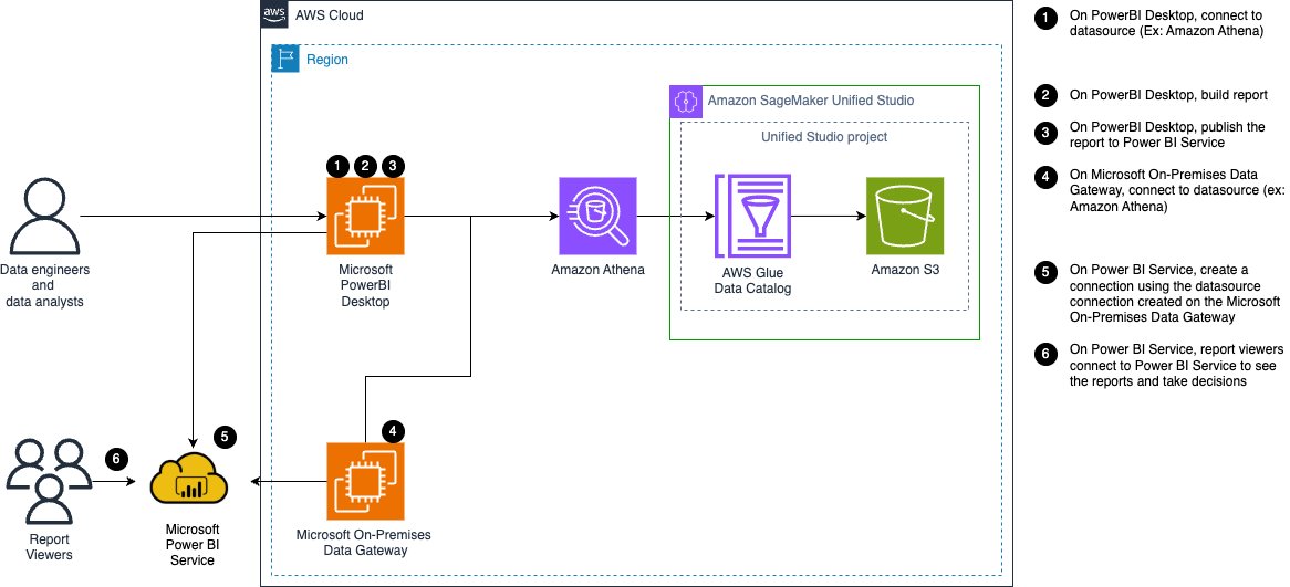
The following diagram illustrates the solution architecture for connecting Power BI to Amazon SageMaker Unified Studio through Amazon Athena.

Architecture diagram showing Power BI connecting to Amazon Athena through Amazon SageMaker Unified Studio, with a Microsoft on-premises data gateway on Amazon EC2

Figure 1: Architecture diagram

The following architecture demonstrates a six-step workflow.

  1. Data engineers and analysts connect Power BI Desktop to Athena as a data source.
  2. They build their reports locally.
  3. They then publish them to the Power BI Service.
  4. Microsoft On-Premises Data Gateway on an Amazon Elastic Compute Cloud (Amazon EC2) instance connects to Athena using the instance’s attached IAM role.
  5. The Power BI Service then uses this gateway connection.
  6. Report viewers access the published reports through Power BI Service to make data-driven decisions.

On the AWS side, Athena queries the data catalog managed by AWS Glue Data Catalog. The catalog references data stored in Amazon Simple Storage Service (Amazon S3). An Amazon SageMaker Unified Studio project governs all access.

In an IDC-based domain (covered in this post), Power BI Desktop uses SageMakerBrowserIdc for Method 1 and SageMakerIam for Method 2. Power BI Desktop can run on-premises or on an EC2 instance. The gateway always uses SageMakerIam (it runs as a Windows service without browser access) and authenticates using instance profile credentials, which rotate automatically. The gateway can only query data within projects where its IAM role has been added as a member. For IAM-based domains, see Part 2.

Prerequisites

Before connecting Power BI to Amazon SageMaker Unified Studio, verify that your environment meets these requirements:

  • Athena ODBC driver – The latest Amazon Athena ODBC driver (version 2.2.0 or more recent) for Windows 64-bit.
  • Microsoft Power BI Desktop – The latest version installed on your Windows machine.
  • Microsoft Power BI Pro License – Required for publishing reports and configuring the on-premises data gateway.
  • Microsoft Power BI on-premises data gateway – The latest version installed on the EC2 instance.
  • Amazon SageMaker Unified Studio – An Amazon SageMaker Unified Studio IDC-based domain.

You need an Amazon SageMaker Unified Studio project with data assets. For detailed instructions, refer to the Amazon SageMaker Unified Studio User Guide.

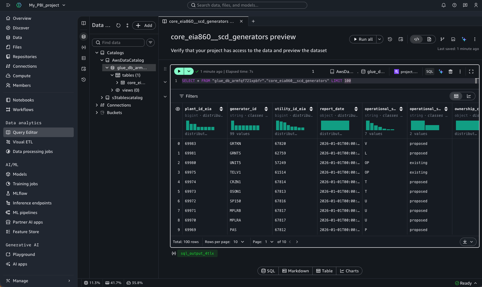
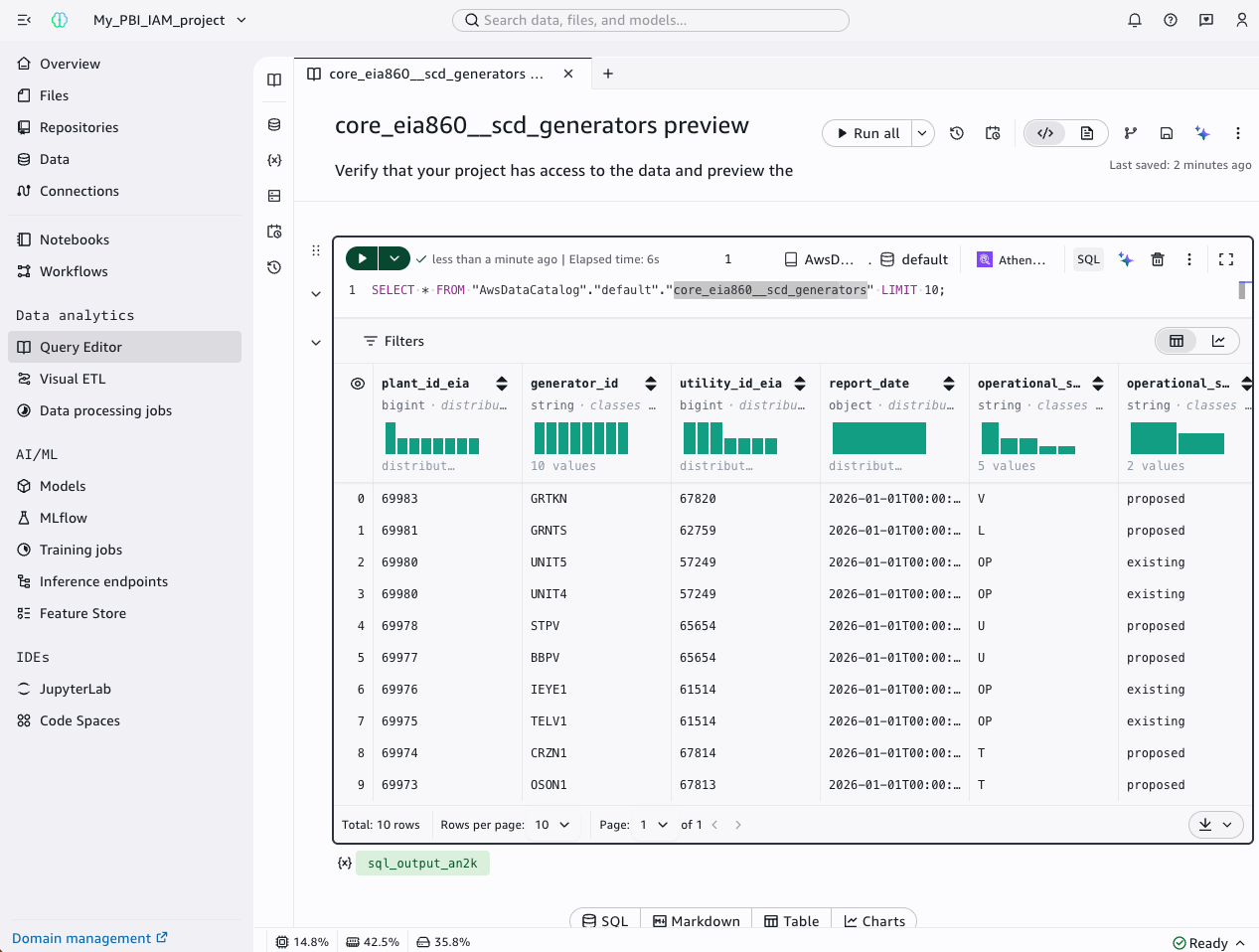
The following screenshot shows the Amazon SageMaker Unified Studio project Query Editor interface, which runs a preview query against the EIA-860 generators dataset.

SageMaker Unified Studio Query Editor previewing the EIA-860 generators dataset

Figure 2: SageMaker Unified Studio project with the EIA-860 generators dataset available in the data catalog

Method 1: DSN-based connection (Athena Power BI connector)

This method uses the Amazon Athena Power BI connector with an ODBC Data Source Name (DSN), supporting DirectQuery and Import mode.

You configure Power BI Desktop to connect to your data assets in Amazon SageMaker Unified Studio using the SageMakerBrowserIdc authentication mode. The driver opens a browser window and authenticates through IAM Identity Center (and your external identity provider, if configured).

Add your SSO user as a member of your SageMaker Unified Studio project

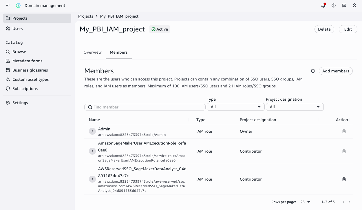
Your single sign-on (SSO) user needs project-level access to query data with Athena. Verify your user is listed as a project member or add it by following Add project members in the Amazon SageMaker Unified Studio User Guide.

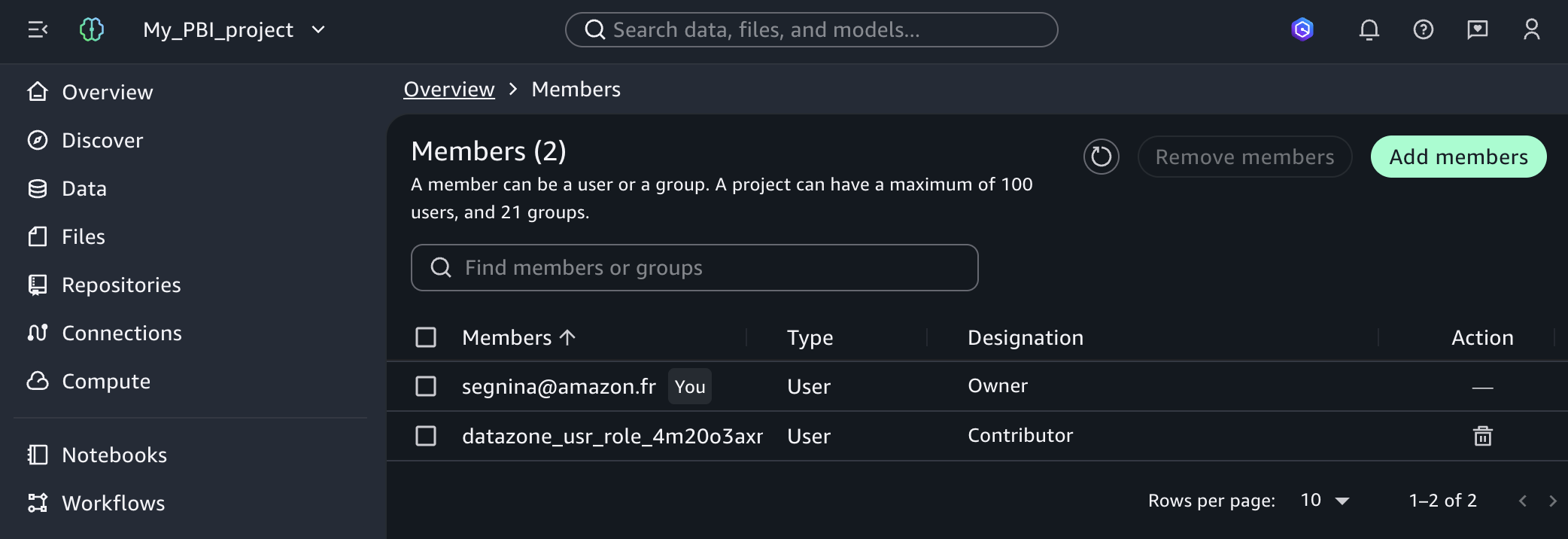
The following screenshot shows the SageMaker Unified Studio project user management page, where project owners can add or remove project users and roles.

SageMaker Unified Studio project members page listing users and roles

Figure 3: Members of a SageMaker Unified Studio project

Gather configuration values to configure your Amazon Athena ODBC DSN

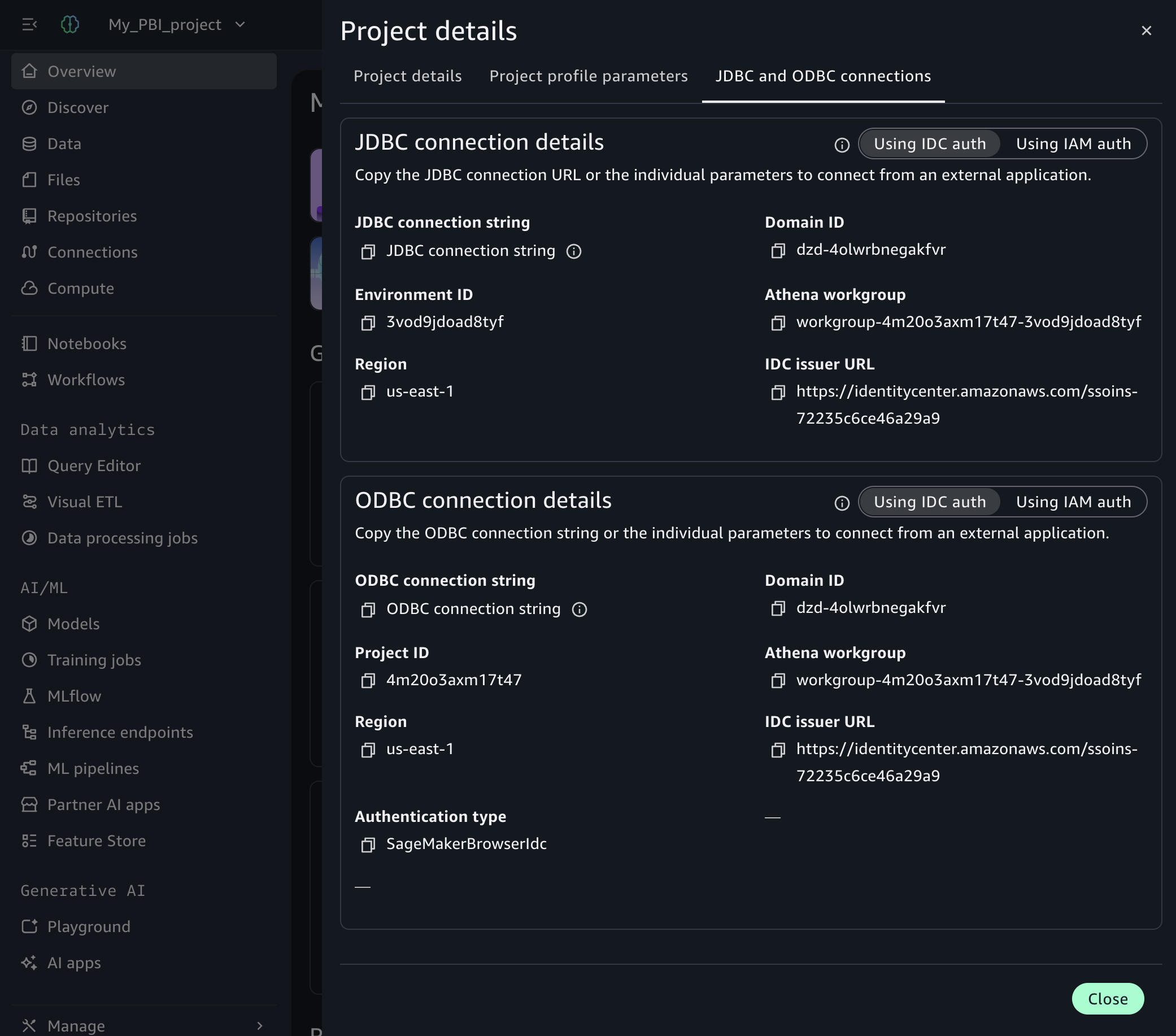
Gather the following values from your Amazon SageMaker Unified Studio project:

  1. Open your Amazon SageMaker Unified Studio project.
  2. In the top right, select the three dots.
  3. Choose Project details.
  4. Select JDBC and ODBC details.
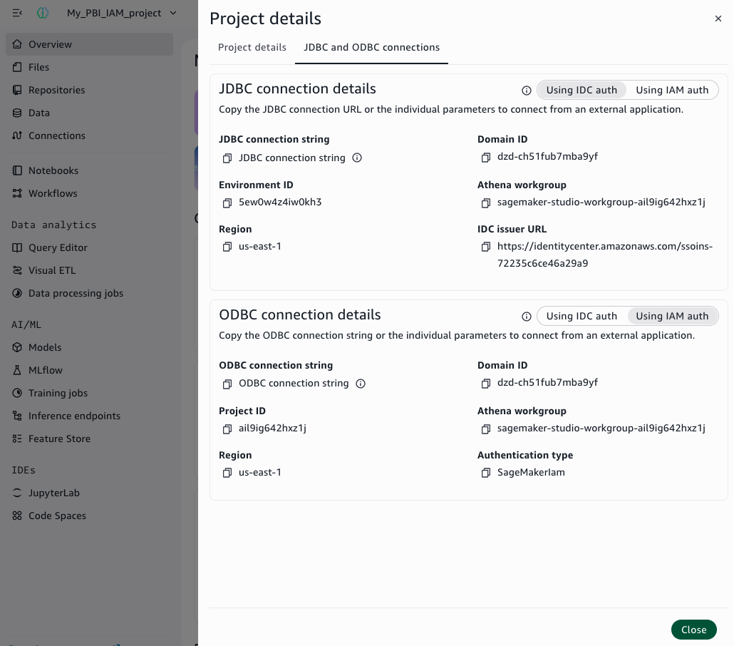
  5. Under ODBC connection details copy the following information: IDC issuer URL, domain ID, project ID, Athena workgroup name and AWS Region.

The following screenshot shows the Amazon SageMaker Unified Studio project overview page, where you can copy these details.

SageMaker Unified Studio project overview showing ODBC connection details

Figure 4: ODBC connection details

Configure the ODBC DSN

Create a System DSN using the Amazon Athena ODBC driver. For the general DSN creation steps, see Configuring a data source name on Windows in the Amazon Athena User Guide.

Enter the following values:

Field Value
Data Source Name Name your datasource (for example, pbi-idcdomain)
Region The AWS Region where your Amazon SageMaker domain is provisioned (for example, us-east-1)
Catalog AwsDataCatalog
Database default
Workgroup Your Athena workgroup name (for example, workgroup-abcdefghij-klmexample)

In the Authentication Options, configure the following values:

Field Value
Authentication Type SageMakerBrowserIdc
SSO Start URL IAM Identity Center entry point (for example, https://identitycenter.amazonaws.com/ssoins-0example)
SSO Region Region of IAM Identity Center (for example, us-east-1)
SageMaker Domain ID dzd-123456example
SageMaker Project ID abcd12example
SageMaker Domain Region Region of your Amazon SageMaker Unified Studio project (for example, us-east-1)

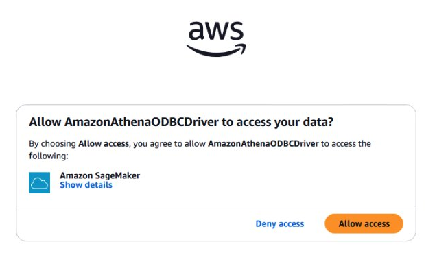
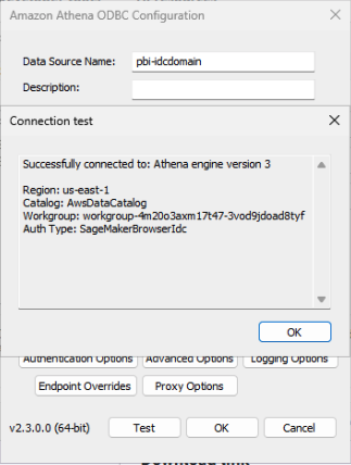
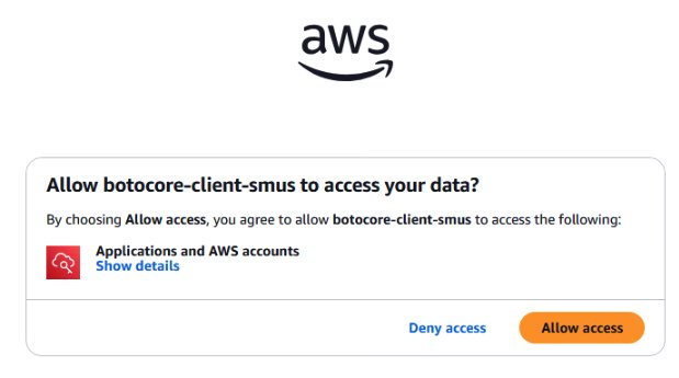
Choose OK, then Test to verify the connection. Choose Allow Access when prompted by the browser.

The following screenshot shows the consent prompt.

Browser consent prompt requesting access approval during authentication

Figure 5: Browser consent prompt

The following screenshot shows the successful connection test.

ODBC DSN configuration showing a successful connection test with SageMakerBrowserIdc

Figure 6: Successful connection test in the ODBC DSN configuration with SageMakerBrowserIdc authentication

Connect Power BI Desktop to your data

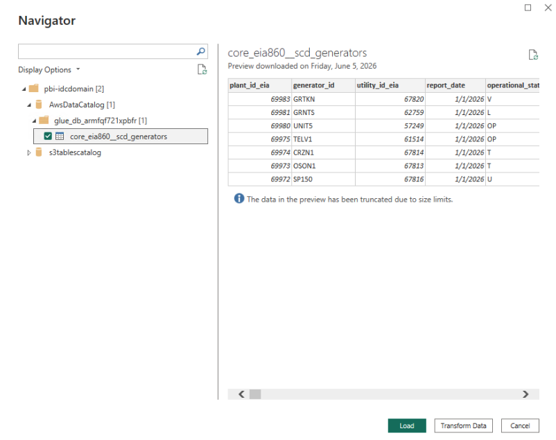
With the DSN configured, you can connect Power BI Desktop to your data catalog and load the generators dataset.

  1. Open Power BI Desktop.
  2. Open the Get Data menu and select More.
  3. Search for and select Amazon Athena and choose Connect.
  4. For Data Source Name (DSN), enter pbi-idcdomain.
  5. Select DirectQuery.
  6. Choose OK.
  7. Choose Use Data Source Configuration and then Connect.
  8. In the AwsDataCatalog folder, navigate to your database.
  9. Select the core_eia860__scd_generators table.
  10. Choose Load.

The following screenshot shows Power BI Desktop successfully connected to the AWS data catalog.

Power BI Desktop connected to the data catalog with the generators table loaded

Figure 7: Power BI Desktop connected to the data catalog with the generators table loaded using SageMakerBrowserIdc authentication

Create your dashboard and publish it

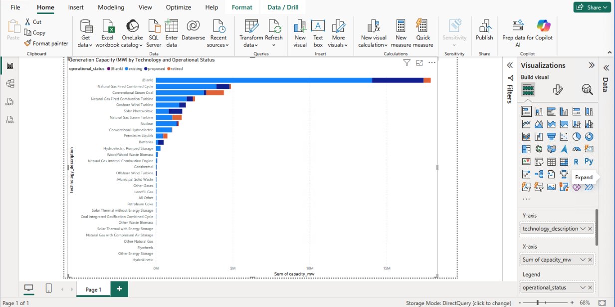
You can create a dashboard to visualize U.S. power generation data. To create a visualization, complete the following steps:

  1. In the Visualizations pane, choose the Stacked bar chart.
  2. Assign the Y-Axis: Drag technology_description to the Y-Axis.
  3. Assign the X-Axis (Values): Drag capacity_mw to the X-Axis (automatically summed).
  4. Assign the Legend (Stack): Drag operational_status to the Legend field.
  5. Choose Publish.
  6. Give your report a name (for example, generation-idcdomain) and choose Save.
  7. Sign in and choose a destination workspace.
Power BI Desktop stacked bar chart of generation capacity by technology and operational status

Figure 8: Power BI Desktop report using the EIA-860 generators dataset

After publishing, the report structure is available on Power BI Service.

Method 2: DSN-less connection (Power BI ODBC connector)

In this method, you use the Power BI ODBC connector with a connection string (no DSN required). This method supports Import mode only and SageMakerIam authentication. Because the gateway cannot perform browser authentication, both Desktop and gateway must use SageMakerIam. If your workflow requires SageMakerBrowserIdc, use Method 1.

If your machine already has AWS credentials through another method in the default credential provider chain, skip the following setup.

Administrator setup

Create a custom permission set named SageMakerDataAnalyst in IAM Identity Center with the following inline policy. For detailed steps, see Create a permission set in the AWS IAM Identity Center User Guide.

{
    "Version": "2012-10-17",
    "Statement": [
        {
            "Sid": "SageMakerAccess",
            "Effect": "Allow",
            "Action": [
                "datazone:GetConnection",
                "datazone:ListConnections",
                "datazone:GetDomain",
                "datazone:GetProject"
            ],
            "Resource": "*"
        },
        {
            "Sid": "STSForDriver",
            "Effect": "Allow",
            "Action": [
                "sts:GetCallerIdentity"
            ],
            "Resource": "*"
        }
    ]
}

Assign your user to this permission set for the AWS account containing your SageMaker Unified Studio domain. Then configure your AWS Command Line Interface (AWS CLI) SSO profile by running aws configure sso. For the full CLI configuration walkthrough with detailed steps, see Part 2. After your profile is configured, run aws sso login to authenticate.

Add the IAM identity as a member of SageMaker Unified Studio project

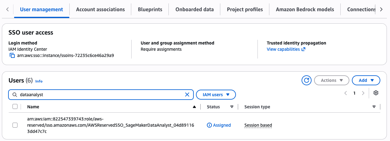
The IAM identity providing credentials needs both domain-level and project-level access to query data through Athena.

  1. Add AWSReservedSSO_SageMakerDataAnalyst_1234example as a domain IAM user: see Managing users in the Amazon SageMaker Unified Studio Admin Guide. Choose Current account.
SageMaker Unified Studio domain users list including the IAM identity

Figure 9: List of users of your SageMaker Unified Studio domain including the IAM identity

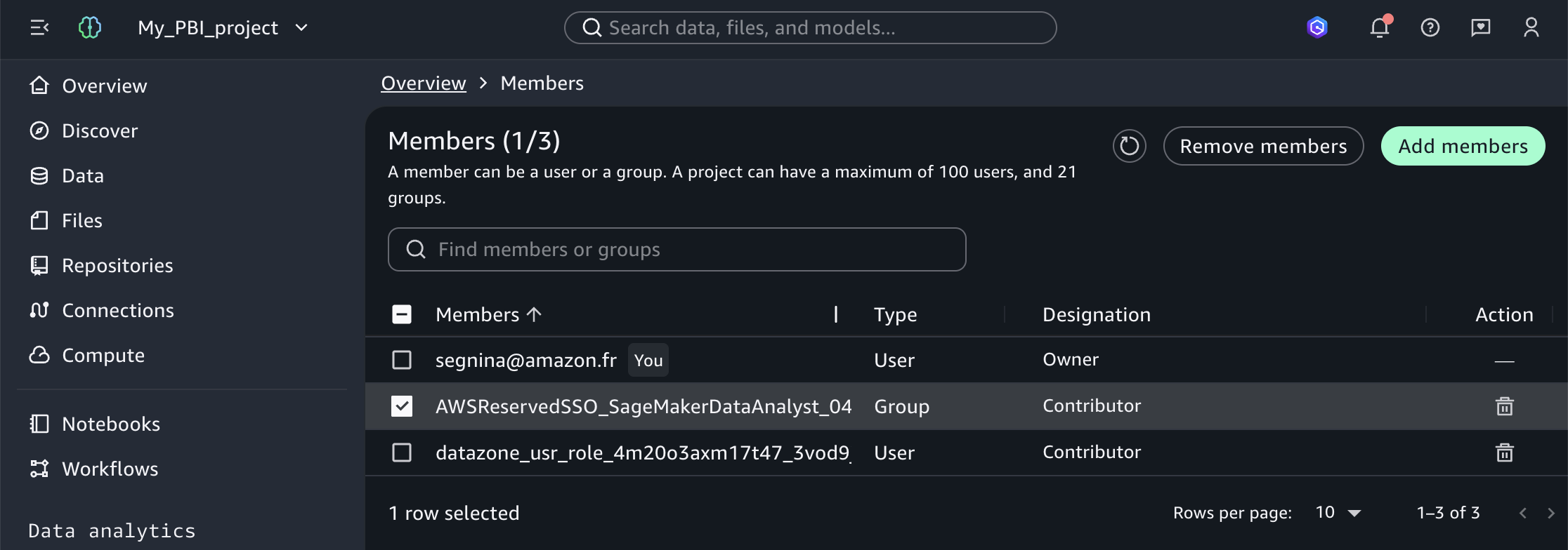
  1. Add AWSReservedSSO_SageMakerDataAnalyst_1234example as a project member: see Add project members in the Amazon SageMaker Unified Studio User Guide.
SageMaker Unified Studio project members list including the IAM identity

Figure 10: Members of a SageMaker Unified Studio project including the IAM identity

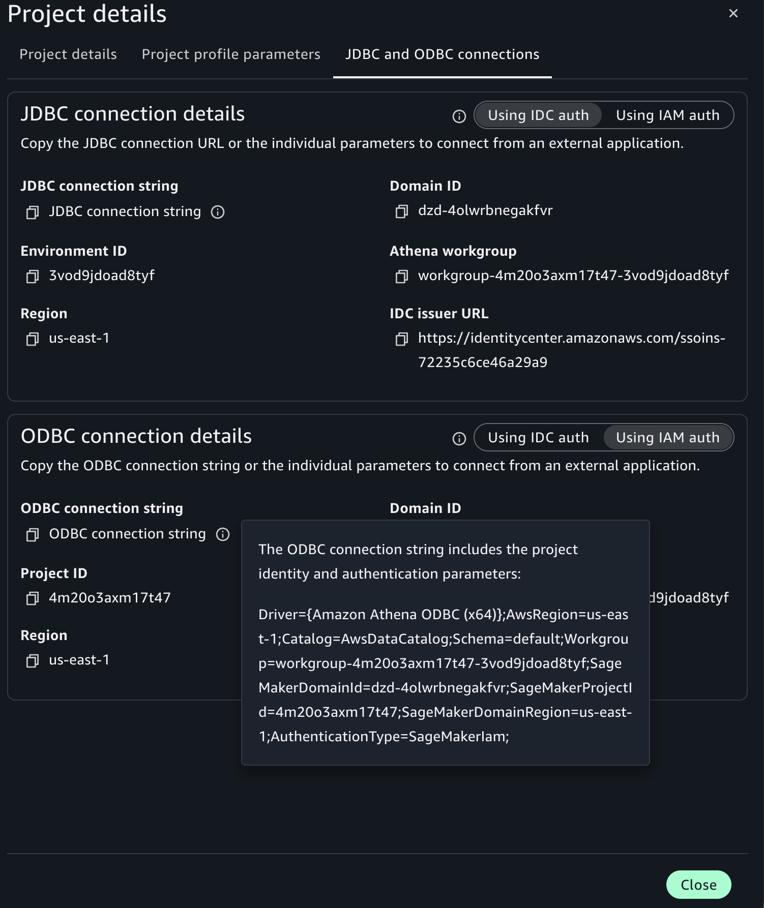
Gather configuration values

Gather the following connection values from your Amazon SageMaker Unified Studio project:

  1. Open your Amazon SageMaker Unified Studio Project.
  2. On the navigation pane, choose Overview.
  3. Select JDBC and ODBC details.
  4. Select the Using IAM auth toggle.
  5. Copy the ODBC connection string.
SageMaker Unified Studio project overview showing the ODBC connection string for IAM auth

Figure 11: ODBC connection string on the SageMaker Unified Studio project overview

Connect Power BI Desktop to your data and publish

With the configuration parameters of your project, you can connect Power BI Desktop to your data catalog and load the generators dataset.

  1. Open Power BI Desktop.
  2. Open the Get Data menu and select More.
  3. Search for and select ODBC and choose Connect.
  4. For Data Source Name (DSN), select (None).
  5. Expand Advanced Options.
  6. In the Connection string field, enter your connection string. For example, Driver={Amazon Athena ODBC (x64)};AwsRegion=us-east-1;Catalog=AwsDataCatalog;Schema=default;Workgroup=workgroup-abcdefghij-klmexample;SageMakerDomainId= dzd-123456example;SageMakerProjectId= abcd12example;SageMakerDomainRegion=us-east-1;AuthenticationType=SageMakerIam;
  7. Choose OK.
  8. Choose Default or Custom and then Connect.
  9. In the AwsDataCatalog folder, navigate to your database.
  10. Select the core_eia860__scd_generators table.
  11. Choose Load.

When publishing, name your report generation-idcdomain-dsnless.

Configure the on-premises data gateway and view your report on Power BI Service

After creating your reports in Power BI Desktop, configure the on-premises data gateway to view your report on Power BI Service.

You can configure the gateway using either a DSN or a DSN-less connection string, matching the method you used in Power BI Desktop.

Create and attach an IAM role to the Power BI Gateway EC2 instance

Create an IAM role for the EC2 instance that will host your Power BI gateway. Name the role pbi-gateway-role (or a name of your choice). The role must use EC2 as the trusted entity and include the following inline policy:

{
    "Version": "2012-10-17",
    "Statement": [
        {
            "Sid": "SageMakerAccess",
            "Effect": "Allow",
            "Action": [
                "datazone:GetConnection",
                "datazone:ListConnections",
                "datazone:GetDomain",
                "datazone:GetProject"
            ],
            "Resource": "*"
        },
        {
            "Sid": "STSForDriver",
            "Effect": "Allow",
            "Action": [
                "sts:GetCallerIdentity"
            ],
            "Resource": "*"
        }
    ]
}

Attach this role to your Power BI Gateway EC2 instance. For detailed steps on creating and attaching an IAM role to an EC2 instance, refer to IAM roles for Amazon EC2 in the Amazon EC2 User Guide.

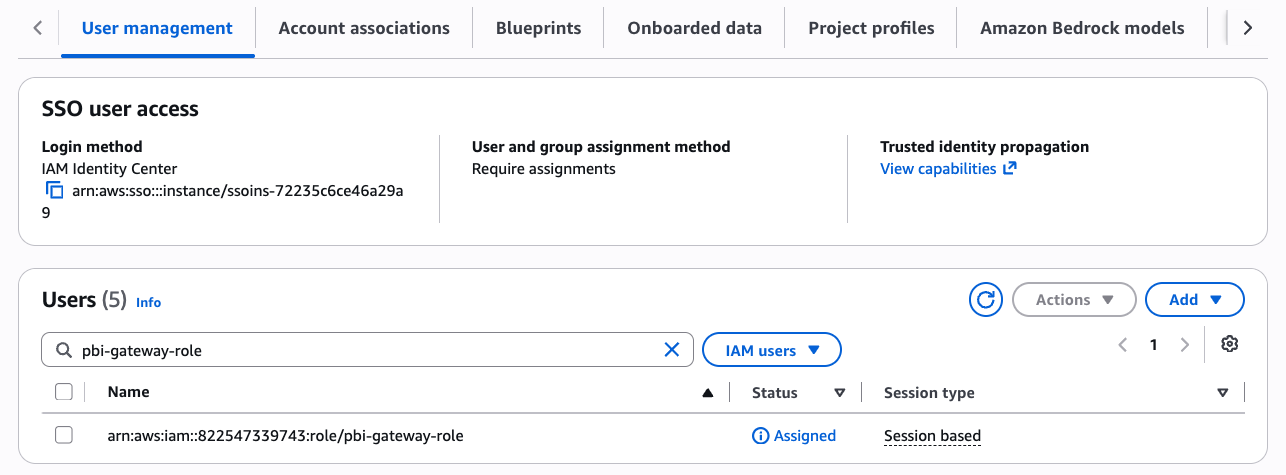
Add the Power BI Gateway IAM role as a member of SageMaker Unified Studio project

The gateway IAM role needs project-level access to query data through Athena.

  1. Add the IAM pbi-gateway-role role as a domain IAM user: see Managing users in the Amazon SageMaker Unified Studio Admin Guide. Choose Current account (or Associated account if your gateway is deployed in a different account).

The following screenshot, from the Amazon SageMaker page of the AWS Management Console, shows the list of users of your Amazon SageMaker Unified Studio domain, including the IAM gateway role.

SageMaker Unified Studio domain users list including the Power BI gateway IAM role

Figure 12: List of users of your SageMaker Unified Studio domain including the IAM gateway role

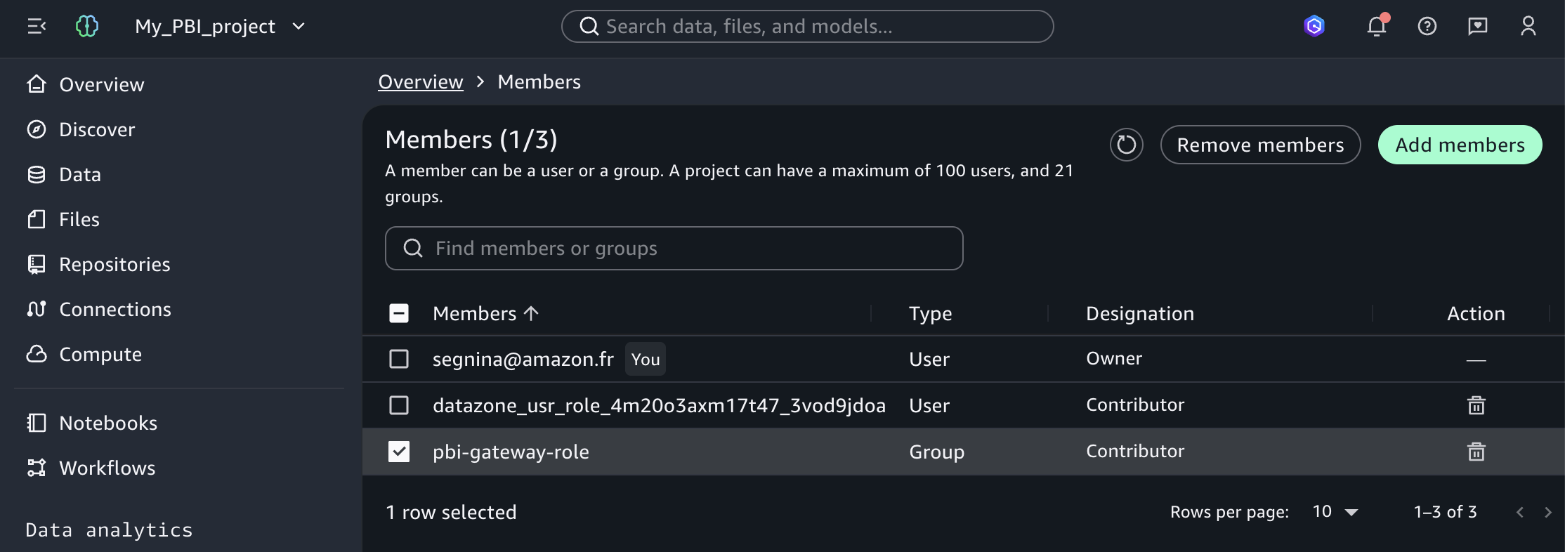
Add the IAM pbi-gateway-role role as a project member: see Add project members in the Amazon SageMaker Unified Studio User Guide.

The following screenshot shows the Amazon SageMaker Unified Studio project user management page listing the project members.

SageMaker Unified Studio project members list including the Power BI gateway IAM role

Figure 13: Members of a SageMaker Unified Studio project including the IAM gateway role

Configure the data source on Power BI Gateway

How you configure the data source depends on the method you used in Power BI Desktop.

Method 1 (DSN-based)

Configure a System DSN on the gateway EC2 instance following the same ODBC DSN steps described in Method 1. When configuring, make sure that:

  • You use the System DSN tab (not User DSN) because the gateway runs as a Windows service under a separate account.
  • The authentication type is set to SageMakerIam regardless of what you used on Desktop.
  • The DSN name matches exactly the one configured on Power BI Desktop (for example, pbi-idcdomain)

Method 2 (DSN-less)

No configuration is needed on the gateway machine itself. You configure the data source directly in Power BI Service.

Configure the data source and view your report on Power BI Service

To view your report, complete the following steps:

  1. Open the workspace where you saved your report.
  2. Search the Semantic Model which has the same name as your report (for example, generation-idcdomain) and choose the More options icon (three dots).
  3. Choose Settings.
  4. Expand Gateway and Cloud Connection.
  5. Choose View Datasources (play icon) on your gateway.
  6. Choose Manually add to gateway.
  7. Add a connection name (for example, pbi-idcdomain).

The next step depends on the method that you chose:

Method 1 (DSN-based)

  1. Add the DSN (for example, pbi-idcdomain) that matches exactly the one configured on Power BI Desktop.

Method 2 (DSN-less)

  1. In the Connection string field, enter the connection string that matches exactly the one used in Power BI Desktop.

Next, continue with the configuration:

  1. Select Anonymous as Authentication Method.
  2. Choose Create.
  3. Expand again Gateway and Cloud Connection.
  4. For Maps to, choose the connection that you created (for example, pbi-idcdomain).
  5. Choose Apply.
  6. Return to the workspace where you saved your report.
  7. On the Content section, choose your report (for example, generation-idcdomain).

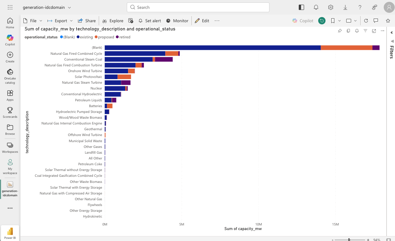
The following screenshot shows a Power BI report on Power BI Service.

Published Power BI report rendering on Power BI Service

Figure 14: Power BI report on Power BI Service

You can now see your report online with the data from your Amazon SageMaker Unified Studio project.

Clean up

To avoid additional charges after testing, delete the Amazon SageMaker Unified Studio domain and EC2 instances. Refer to Delete domains and Terminate Instances for instructions.

Conclusion

In this post, you connected Microsoft Power BI to Amazon SageMaker Unified Studio using an IDC-based domain with both DSN-based and DSN-less methods. This provides a direct connection, with no third-party licensing, that maintains data governance. In Part 2, we cover IAM-based domains.

You can automate many steps of this process. For information about automating DSN creation on the Power BI Gateway or Service, refer to How ENGIE automates the deployment of Amazon Athena data sources on Microsoft Power BI. If you don’t want users adding the gateway IAM role directly, you can create a custom blueprint as a self-service tool for gateway role addition. The blueprint uses a ProjectMembership resource with a configurable parameter that project owners can activate at project creation, automatically adding the gateway role as a project contributor.

For additional best practices, refer to the Using Microsoft Power BI with the AWS Cloud Whitepaper. To learn more, visit Amazon SageMaker Unified Studio and Amazon Athena.


About the authors

Ramesh Singh

Ramesh Singh

Ramesh is a Senior Product Manager Technical (External Services) at AWS in Seattle, Washington, currently with the Amazon SageMaker team. He is passionate about building high-performance ML/AI and analytics products that help enterprise customers achieve their critical goals.

Armando Segnini

Armando Segnini

Armando is a Senior Analytics Specialist Solutions Architect at AWS, partnering with enterprise customers to architect scalable data, analytics, and AI platforms. He helps organizations turn complex data challenges into business value through expertise in streaming, BI integration, and generative AI. Outside of work, Armando enjoys traveling with his family, exploring new cultures, photography, and functional fitness competitions.

Gaurav Sharma

Gaurav is a Specialist Solutions Architect (Analytics) at AWS, supporting US public sector customers on their cloud journey. Outside of work, Gaurav enjoys spending time with his family and reading books.

Krishna Atluru

Krishna Atluru

Krishna is an Enterprise Support Lead TAM at AWS. He provides customers with in-depth guidance on improving security posture and operational excellence for their workloads, helping them build secure, resilient, and cost-effective solutions. His areas of expertise include building serverless architectures, and data and analytics solutions. Outside of work, Krishna enjoys cooking, swimming, and traveling.

Saushthav Saxena

Saushthav Saxena

Saushthav is a Software Development Engineer at AWS on the Amazon Athena team, where he has spent the past few years working on distributed systems and data analytics at scale. Based in the San Francisco Bay Area, his background spans full-stack development, high performance computing, and large-scale infrastructure. Outside of work, he enjoys reading sci-fi novels, swimming, and traveling with family and friends.

Connect Amazon SageMaker Unified Studio to Microsoft Power BI – Part 2: IAM-based domains

Post Syndicated from Ramesh H Singh original https://aws.amazon.com/blogs/big-data/connect-amazon-sagemaker-unified-studio-to-microsoft-power-bi-part-2-iam-based-domains/

In Part 1 of this series, we connected Microsoft Power BI to Amazon SageMaker Unified Studio using an IAM Identity Center (IDC)-based domain. The Amazon Athena ODBC driver (version 2.2.0 and later) supports Amazon SageMaker Unified Studio authentication natively, removing the third-party ODBC-JDBC bridge previously required. We walked through both the DSN-based connection and the DSN-less connection, from Power BI Desktop through the on-premises data gateway to Power BI Service, where report viewers access published dashboards.

In this post, you create the same direct connection using an AWS Identity and Access Management (IAM)-based domain. The walkthrough covers the same two connection methods. The differences are the Amazon SageMaker Unified Studio console navigation paths, the configuration values, and an additional administrator setup that provides AWS credentials through AWS IAM Identity Center. This is Part 2 of a two-part series. For a detailed comparison of the two connection methods, see Part 1.

Solution overview

The architecture is the same as the previous post (see the architecture diagram and walkthrough scenario in Part 1). Power BI Desktop connects to Amazon Athena through the ODBC driver and the Amazon SageMaker Unified Studio project governs all data access. At the same time, the on-premises data gateway on an Amazon Elastic Compute Cloud (Amazon EC2) instance bridges the connection to Power BI Service so report viewers can access published dashboards.

The difference is in authentication: An IAM-based domain uses SageMakerIam authentication for both connection methods. The driver retrieves credentials from the AWS default credential provider chain. For this walkthrough, AWS IAM Identity Center provides those credentials through a custom permission set. Power BI Desktop can run on-premises or on an EC2 instance in the AWS Cloud. The gateway EC2 instance authenticates using its attached IAM role.

Prerequisites

Complete the prerequisites from Part 1. Additionally, you need:

  • AWS Command Line Interface (AWS CLI) – The latest version of the AWS CLI installed on your Windows machine. In this post series, the ODBC driver uses the AWS IAM Identity Center profile configured through the CLI for authentication.
  • Amazon SageMaker Unified Studio – An Amazon SageMaker Unified Studio IAM-based domain with AWS IAM Identity Center single sign-on (SSO) enabled.

The following screenshot shows the Amazon SageMaker Unified Studio (IAM-based domain) project Query Editor interface. It runs a preview query on the EIA-860 generators dataset.

SageMaker Unified Studio Query Editor previewing the EIA-860 generators dataset in an IAM-based domain

Figure 1: SageMaker Unified Studio (IAM-based domain) project with the EIA-860 generators dataset available in the data catalog

Administrator setup

This section configures AWS IAM Identity Center to provide credentials for the SageMakerIam authentication mode. It applies to Method 1 (IAM-based domain) and Method 2 (both domain types). If your machine already has AWS credentials available through another method in the default credential provider chain, you can skip this section and proceed directly to the method of your choice. For the full list of credential sources, refer to Credential providers in the AWS SDKs and Tools Reference Guide.

Create a permission set in IAM Identity Center

Create a custom permission set named SageMakerDataAnalyst in IAM Identity Center with the following inline policy. For detailed steps, see Create a permission set in the AWS IAM Identity Center User Guide.

{
    "Version": "2012-10-17",
    "Statement": [
        {
            "Sid": "SageMakerAccess",
            "Effect": "Allow",
            "Action": [
                "datazone:GetConnection",
                "datazone:ListConnections",
                "datazone:GetDomain",
                "datazone:GetProject"
            ],
            "Resource": "*"
        },
        {
            "Sid": "STSForDriver",
            "Effect": "Allow",
            "Action": [
                "sts:GetCallerIdentity"
            ],
            "Resource": "*"
        }
    ]
}

The "Resource": "*" is required because these API actions do not support resource-level permissions. For more information, see Actions, resources, and condition keys for Amazon DataZone.

This doesn’t grant broad access to your data. These are read-only metadata actions that allow the ODBC driver to discover connection details and retrieve temporary Athena credentials. The actual data access is governed by Amazon SageMaker Unified Studio project membership: Users can only query data within projects where they have been explicitly added as members. The Amazon SageMaker Unified Studio project IAM role provides Athena and Amazon S3 permissions separately.

Assign users to the permission set

To assign users or groups to the target AWS account, complete the following steps:

  1. In the IAM Identity Center console, choose AWS accounts.
  2. Select the target account where your Amazon SageMaker Unified Studio IAM-based domain is deployed.
  3. Choose Assign users or groups.
  4. Select the SSO users or groups that need access.
  5. Select the SageMakerDataAnalyst permission set.
  6. Choose Submit.

Configure AWS IAM Identity Center profile

To configure the AWS IAM Identity Center profile, run the following command in your terminal on Windows:

aws configure sso

When prompted, enter the following values:

Prompt Value
SSO session name For example, smus
SSO start URL The IDC issuer URL. For example, https://identitycenter.amazonaws.com/ssoins-0example
SSO region The SSO Region. For example, us-east-1
SSO registration scopes sso:account:access

A browser window opens for authentication. After authentication, select your account and the SageMakerDataAnalyst role.

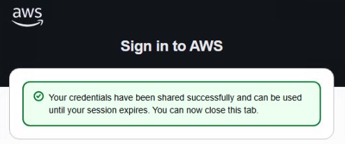
The following screenshots show the consent window and the successful authentication message.

Browser consent prompt requesting access approval during AWS CLI SSO authentication

Figure 2: Browser consent prompt

Browser page confirming successful AWS CLI SSO authentication

Figure 3: Browser authentication successful message

When prompted, enter the following values:

Prompt Value
Default client Region None
CLI default output format None
Profile Name Change value by default

The resulting ~/.aws/config file should look like the following:

[default]
sso_session = smus
sso_account_id = 1234example
sso_role_name = SageMakerDataAnalyst

[sso-session smus]
sso_start_url = https://identitycenter.amazonaws.com/ssoins-0example
sso_region = us-east-1
sso_registration_scopes = sso:account:access

Verify authentication and daily use

To verify that your SSO profile is working correctly, run the following command:

aws sts get-caller-identity

You should receive a response like the following:

{
    "UserId": "AROARHJJNFBQD6EXAMPLE:[email protected]",
    "Account": "111122223333",
    "Arn": "arn:aws:sts::111122223333:assumed-role/AWSReservedSSO_SageMakerDataAnalyst_1234example/[email protected]"
}

For daily use, no passwords or EC2 instance roles are required. When your SSO session expires, run the following command to quickly refresh it:

aws sso login

Add your IAM identity as a member of your Amazon SageMaker Unified Studio project

The IAM identity providing credentials to the ODBC driver needs project-level access to query data through Athena. If you completed the administrator setup, this is the SSO role associated with your permission set (for example, AWSReservedSSO_SageMakerDataAnalyst_1234example). If you’re using another credential source, add the IAM role or user that provides those credentials. For detailed steps, see Managing users for IAM-based domains in the Amazon SageMaker Unified Studio Administrator Guide.

The following screenshot shows the Amazon SageMaker Unified Studio domain management page, which lists the members in a project.

SageMaker Unified Studio project members list

Figure 4: List of members of your SageMaker Unified Studio project

Gather the information to authenticate

To get the parameters that you need to authenticate, complete these steps:

  1. Open your Amazon SageMaker Unified Studio Project.
  2. Open Domain Management.
  3. Choose Users.
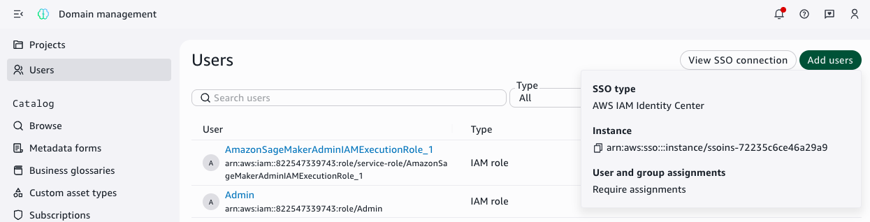
  4. Choose View SSO connection.
  5. Copy the end of the Instance ARN, so we can build the Instance URL like https://identitycenter.amazonaws.com/ssoins-0example

The following screenshot shows the Amazon SageMaker Unified Studio domain management page with SSO connection details.

SageMaker Unified Studio domain SSO connection details showing the IAM Identity Center instance ARN

Figure 5: AWS IAM Identity Center information

  1. Choose the user icon and copy the Region as shown in the following screenshot.
SageMaker Unified Studio user menu showing the Region

Figure 6: User icon with the Region information

Method 1: DSN-based connection (Athena Power BI connector)

In this method, you configure an ODBC Data Source Name (DSN) and use the Amazon Athena connector in Power BI. This method uses SageMakerIam authentication mode and supports both DirectQuery and Import mode.

This section covers IAM-based domains. For IDC-based domains, see Part 1.

Gather configuration values to configure your Amazon Athena ODBC DSN

Before configuring the ODBC DSN, gather the following connection values from your Amazon SageMaker Unified Studio project:

  1. Open your Amazon SageMaker Unified Studio Project.
  2. Top right, select the three dots.
  3. Choose Project details.
  4. Select JDBC and ODBC details.
  5. Copy the following values: domain ID, Amazon SageMaker project ID, AWS Region, and Athena workgroup.

The following screenshot shows the Amazon SageMaker Unified Studio project overview page, which provides the project details to copy.

SageMaker Unified Studio project details showing domain ID, project ID, Region, and Athena workgroup

Figure 7: Project details with SageMaker domain ID, SageMaker project ID, Region, and Athena workgroup

Configure the ODBC DSN

Create a System DSN using the Amazon Athena ODBC driver. For the general DSN creation steps, see Configuring a data source name on Windows in the Amazon Athena User Guide. Enter the following values:

Field Value
Data Source Name Name your datasource (for example, pbi-iamdomain)
Region The AWS Region where your Amazon SageMaker domain is provisioned (for example, us-east-1)
Catalog AwsDataCatalog
Database default
Workgroup Your Athena workgroup name (for example, workgroup-abcdefghij-klmexample)

In the Authentication Options, configure the following values:

Field Value
Authentication Type SageMakerIam
SageMaker Domain ID dzd-123456example
SageMaker Project ID abcd12example
SageMaker Region Region of your SageMaker Unified Studio project (for example, us-east-1)

Choose OK, then Test to verify the connection. Choose Allow Access when prompted by the browser.

The following screenshot shows the successful connection test.

ODBC DSN configuration showing a successful connection test with SageMakerIam

Figure 8: Successful connection test in the ODBC DSN configuration with SageMakerIam authentication

Connect Power BI Desktop to your data

With the DSN configured, you can connect Power BI Desktop to your data catalog and load the generators dataset.

  1. Open Microsoft Power BI Desktop.
  2. Open the Get Data menu and select More.
  3. Search for and select Amazon Athena and choose Connect.
  4. For Data Source Name (DSN), enter pbi-iamdomain.
  5. Select DirectQuery.
  6. Choose OK.
  7. Choose Use Data Source Configuration and then Connect.
  8. In the AwsDataCatalog folder, navigate to your database.
  9. Select the core_eia860__scd_generators table.
  10. Choose Load.

The following screenshot shows Power BI Desktop successfully connected to the data catalog.

Power BI Desktop connected to the data catalog with the generators table loaded

Figure 9: Power BI Desktop connected to the data catalog with the generators table loaded using SageMakerIam authentication

Create your dashboard and publish it

You can create a dashboard to visualize U.S. power generation data. To create a visualization, complete the following steps:

  1. In the Visualizations pane, choose the Stacked bar chart.
  2. Assign the Y-Axis: Drag technology_description to the Y-Axis.
  3. Assign the X-Axis (Values): Drag capacity_mw to the X-Axis (automatically summed).
  4. Assign the Legend (Stack): Drag operational_status to the Legend field.
  5. Choose Publish.
  6. Give your report a name (for example, generation-iamdomain) and choose Save.
  7. Sign in and choose a destination workspace.

The following screenshot shows the Power BI dashboard with U.S. power generation data.

Power BI stacked bar chart of U.S. generation capacity by technology and operational status

Figure 10: Power BI dashboard with U.S. power generation data

After you publish, the report structure becomes available on Microsoft Power BI Service.

Method 2: DSN-less connection (Power BI ODBC connector)

In this method, you use the Power BI ODBC connector with a connection string (no DSN required). This method supports Import mode only and SageMakerIam authentication. Because the gateway can’t perform browser authentication and connection strings need to match, both Desktop and gateway must use SageMakerIam.

This section covers IAM-based domains. For IDC-based domains, see Part 1.

Gather configuration values to configure your DSN-less connection

Gather the following connection values from your Amazon SageMaker Unified Studio project:

  1. Open your Amazon SageMaker Unified Studio Project.
  2. Top right, select the three dots.
  3. Choose Project details.
  4. Select JDBC and ODBC details.
  5. Copy the ODBC connection string.

The following screenshot shows the Amazon SageMaker Unified Studio project overview page with the ODBC connection string to copy.

SageMaker Unified Studio project overview showing the ODBC connection string

Figure 11: Project details with ODBC connection string

Connect Power BI Desktop to your data and publish

With the configuration parameters of your project, you can connect Power BI Desktop to your data catalog and load the generators dataset.

  1. Open Power BI Desktop.
  2. Open the Get Data menu and select More.
  3. Search for and select ODBC and choose Connect.
  4. For Data Source Name (DSN), select (None).
  5. Expand Advanced Options.
  6. In the Connection string field, enter your connection string. For example, Driver={Amazon Athena ODBC (x64)};AwsRegion=us-east-1;Catalog=AwsDataCatalog;Schema=default;Workgroup=workgroup-abcdefghij-klmexample;SageMakerDomainId= dzd-123456example;SageMakerProjectId= abcd12example;SageMakerDomainRegion=us-east-1;AuthenticationType=SageMakerIam;
  7. Choose OK.
  8. Choose Default or Custom and then Connect.
  9. In the AwsDataCatalog folder, navigate to your database.
  10. Select the core_eia860__scd_generators table.
  11. Choose Load.

When publishing, name your report generation-iamdomain-dsnless.

Configure the gateway and view your report on Power BI Service

After creating your reports in Power BI Desktop, configure the on-premises data gateway to view your report on Power BI Service.

You can configure the gateway using either a DSN or a DSN-less connection string, matching the method you used in Power BI Desktop.

Create and attach an IAM role to the Power BI Gateway EC2 instance

Create an IAM role for the EC2 instance that will host your Power BI gateway. Name the role pbi-gateway-role (or a name of your choice). The role must use EC2 as the trusted entity and include the following inline policy:

{
    "Version": "2012-10-17",
    "Statement": [
        {
            "Sid": "SageMakerAccess",
            "Effect": "Allow",
            "Action": [
                "datazone:GetConnection",
                "datazone:ListConnections",
                "datazone:GetDomain",
                "datazone:GetProject"
            ],
            "Resource": "*"
        },
        {
            "Sid": "STSForDriver",
            "Effect": "Allow",
            "Action": [
                "sts:GetCallerIdentity"
            ],
            "Resource": "*"
        }
    ]
}

Attach this role to your Power BI Gateway EC2 instance. For detailed steps on creating and attaching an IAM role to an EC2 instance, refer to IAM roles for Amazon EC2 in the Amazon EC2 User Guide.

Add the Power BI Gateway IAM role as a member of SageMaker Unified Studio project

The gateway IAM role needs project-level access to query data through Athena. The steps to add the role differ depending on your domain type.

IAM-based domain

  1. Open your Amazon SageMaker Unified Studio Project.
  2. Open Domain Management.
  3. Choose your Project Name.
  4. Choose Members.
  5. Choose Add members.
  6. Select the IAM role of your Power BI gateway (for example, pbi-gateway-role).
  7. Choose Add.

The following screenshot shows the Amazon SageMaker Unified Studio project domain management page with options to add members to a project.

SageMaker Unified Studio project members list including the Power BI gateway IAM role

Figure 12: List of members of a SageMaker Unified Studio project with the IAM gateway role

Configure the data source on Power BI Gateway

How you configure the data source depends on the method you used in Power BI Desktop.

Method 1 (DSN-based)

Configure a System DSN on the gateway EC2 instance following the same ODBC DSN steps described in Method 1. When configuring, make sure that:

  • You use the System DSN tab (not User DSN) because the gateway runs as a Windows service under a separate account.
  • The authentication type is set to SageMakerIam.
  • The DSN name matches exactly the one configured on Power BI Desktop (for example, pbi-iamdomain).

Method 2 (DSN-less)

No configuration is needed on the gateway machine itself. You configure the data source directly in Power BI Service.

Configure the data source and view your report on Power BI Service

To view your report, complete the following steps:

  1. Open the workspace where you saved your report.
  2. Search the Semantic Model which has the same name as your report (for example, generation-iamdomain) and choose the More options icon (three dots).
  3. Choose Settings.
  4. Expand Gateway and Cloud Connection.
  5. Choose View Datasources (play icon) on your gateway.
  6. Choose Manually add to gateway.
  7. Add a connection name (for example, pbi-iamdomain).

The next step depends on the method that you chose:

Method 1 (DSN-based)

  1. Add the DSN (for example, pbi-iamdomain) that matches exactly the one configured on Power BI Desktop.

Method 2 (DSN-less)

  1. In the Connection string field, enter the connection string that matches exactly the one used in Power BI Desktop.

Next, continue with the configuration:

  1. Select Anonymous as Authentication Method.
  2. Choose Create.
  3. Expand again Gateway and Cloud Connection.
  4. For Maps to, choose the connection that you created (for example, pbi-iamdomain).
  5. Choose Apply.
  6. Return to the workspace where you saved your report.
  7. On the Content section, choose your report (for example, generation-iamdomain).

The following screenshot shows a report on Power BI Service.

Published Power BI report rendering on Power BI Service

Figure 13: Power BI report on Power BI Service

You can now see your report online with the data from your Amazon SageMaker Unified Studio project.

Clean up

To avoid additional charges after testing, delete the Amazon SageMaker Unified Studio domain and EC2 instances. Refer to Delete domains and Terminate Instances for instructions.

Conclusion

In this two-part series, you connected Power BI to Amazon SageMaker Unified Studio through Amazon Athena. Part 1 covered IDC-based domains. This post covered IAM-based domains using SageMakerIam authentication. This provides a direct connection path, with no third-party licensing, while maintaining data governance and security.

You can automate many steps of this process. For information about automating DSN creation on the Power BI Gateway or Service, refer to How ENGIE automates the deployment of Amazon Athena data sources on Microsoft Power BI. If you don’t want users adding the gateway IAM role directly, you can create a custom blueprint as a self-service tool for gateway role addition. The blueprint uses a ProjectMembership resource with a configurable parameter that project owners can activate at project creation, automatically adding the gateway role as a project contributor.

For additional best practices, refer to the Using Microsoft Power BI with the AWS Cloud Whitepaper. To learn more, visit Amazon SageMaker Unified Studio and Amazon Athena.


About the authors

Ramesh H Singh

Ramesh H Singh

Ramesh is a Senior Product Manager Technical at AWS in Seattle, focused on Amazon SageMaker. He’s passionate about building analytics and AI products that help enterprise customers unlock real value from their data. Away from work, he spends his time hiking with family and exploring spirituality. Connect with him on LinkedIn.

Armando Segnini

Armando Segnini

Armando is a Senior Analytics Specialist Solutions Architect at AWS, partnering with enterprise customers to architect scalable data, analytics, and AI platforms. He helps organizations turn complex data challenges into business value through expertise in streaming, BI integration, and generative AI. Outside of work, Armando enjoys traveling with his family, exploring new cultures, photography, and functional fitness competitions.

Gaurav Sharma

Gaurav is a Specialist Solutions Architect (Analytics) at AWS, supporting US public sector customers on their cloud journey. Outside of work, Gaurav enjoys spending time with his family and reading books.

Krishna Atluru

Krishna Atluru

Krishna is an Enterprise Support Lead TAM at AWS. He provides customers with in-depth guidance on improving security posture and operational excellence for their workloads, helping them build secure, resilient, and cost-effective solutions. His areas of expertise include building serverless architectures, and data and analytics solutions. Outside of work, Krishna enjoys cooking, swimming, and traveling.

Saushthav Saxena

Saushthav Saxena

Saushthav is a Software Development Engineer at AWS on the Amazon Athena team, where he has spent the past few years working on distributed systems and data analytics at scale. Based in the San Francisco Bay Area, his background spans full-stack development, high-performance computing, and large-scale infrastructure. Outside of work, he enjoys reading sci-fi novels, swimming, and traveling with family and friends.

Route Amazon Bedrock Guardrails interventions to Amazon Security Lake

Post Syndicated from Dhananjay Karanjkar original https://aws.amazon.com/blogs/security/route-amazon-bedrock-guardrails-interventions-to-amazon-security-lake/

Security teams investigating AI-related incidents need guardrail intervention data alongside their existing security telemetry. Routing Amazon Bedrock Guardrails violations to Amazon Security Lake makes this possible. With this integration, you can query guardrail events alongside identity, network, and application security data in a single layer. When a guardrail blocks a prompt injection attempt or redacts sensitive data, that intervention carries investigative value comparable to a failed sign-in or a network intrusion alert. Amazon Bedrock publishes this telemetry to Amazon CloudWatch metrics and model invocation logs for operational monitoring. By using Security Lake, organizations can extend this telemetry into their security data lake for unified correlation.

In this post, I show you how to build an automated pipeline that transforms Amazon Bedrock Guardrails intervention events into Open Cybersecurity Schema Framework (OCSF) records and delivers them to Security Lake as a custom source. You can query the data using Amazon Athena or any Security Lake subscriber.

Use case

Consider a financial services organization deploying Amazon Bedrock across multiple business units. Each unit uses guardrails to enforce content policies (blocking harmful content), topic policies (preventing off-topic queries about competitors), sensitive information policies (redacting personally identifiable information (PII) such as account numbers), and prompt injection detection.

The security team needs to:

  • Identify which user accounts trigger the most guardrail interventions and whether those accounts also have unusual AWS Identity and Access Management (IAM) activity
  • Determine if prompt injection attempts correlate with specific source IP addresses that also appear in Amazon Virtual Private Cloud (Amazon VPC) Flow Logs
  • Track the organization-wide trend of guardrail violations across all business units and compare it against the baseline from 30 days ago

With guardrail events routed to Security Lake, a single Athena query covers all three.

Solution overview

The pipeline architecture routes Amazon Bedrock security events to Security Lake as OCSF-compliant records. The same infrastructure—subscription filter, AWS Lambda transformation, Parquet writer, Amazon Simple Storage Service (Amazon S3) partitioning—supports multiple event types by changing the filter pattern and OCSF mapping:

Guardrail interventions (this post) DETECTION_FINDING 2004
Model invocation API calls API_ACTIVITY 6003
Agent guardrail traces DETECTION_FINDING 2004
Token consumption anomalies DETECTION_FINDING 2004

This post demonstrates the guardrail interventions implementation as a working example. The solution captures Amazon Bedrock model invocation logs that contain guardrail trace data and filters for intervention events. It transforms matching events into OCSF-compliant Detection Finding records (class_uid 2004) and delivers them to Security Lake as Parquet files. Guardrail interventions are detection events: the guardrail detected and blocked prohibited content, so OCSF class 2004 (Detection Finding) under the Findings category is the appropriate classification.

Architecture

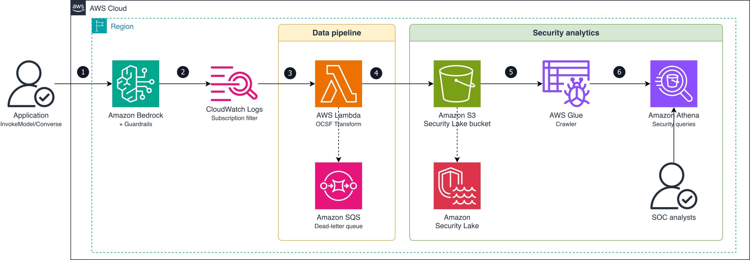
The following diagram shows the end-to-end pipeline from guardrail intervention to Security Lake ingestion.

Figure 1: Guardrail intervention routing

Figure 1: Guardrail intervention routing

The data flow consists of the following steps:

  1. An application calls Amazon Bedrock (InvokeModel or Converse API) with a guardrail attached.
  2. Amazon Bedrock evaluates the guardrail and logs the invocation (including guardrail trace data) to a CloudWatch Logs log group using model invocation logging. The subscription filter matches log entries where the guardrail action is INTERVENED (blocked or masked content).
  3. The subscription filter delivers matching records to a Lambda function (OCSF Transform).
  4. The Lambda function transforms each intervention event into an OCSF Detection Finding record (class_uid 2004), batches records, and converts them to Zstandard (zstd)-compressed Apache Parquet format. It writes the Parquet file to the Amazon S3 Security Lake bucket using the required partition path (ext/BedrockGuardrails/region=/accountId=/eventDay=/). If the Lambda function fails to process a record, the message routes to an Amazon Simple Queue Service (Amazon SQS) dead-letter queue for later analysis and redrive.
  5. Security Lake manages the ingested Parquet data in the S3 bucket.
  6. AWS Glue crawler detects new partitions and catalogs the Parquet files for query access.
  7. SOC analysts query guardrail violation data alongside other security sources using Athena.

OCSF mapping

The following table shows how Amazon Bedrock Guardrails intervention fields map to OCSF Detection Finding (class_uid 2004) attributes.

OCSF field Source Example value
class_uid Static 2004 (Detection Finding)
category_uid Static 2 (Findings)
severity_id Derived from policy type 3 (Medium) for content/topic; 4 (High) for prompt injection
activity_id Static 1 (Create)
time Invocation log timestamp 1721001600000
cloud.provider Static AWS
cloud.region Invocation log region us-east-1
cloud.account.uid Invocation log accountId 123456789012
actor.user.uid Invocation log identity.arn arn:aws:sts::123456789012:assumed-role/AppRole/session
finding_info.title Derived from policy type ContentPolicy Intervention
finding_info.desc Guardrail trace action/topic Blocked: HATE content detected on INPUT
resource.uid Model ARN arn:aws:bedrock:us-east-1::foundation-model/anthropic.claude-sonnet-4-6-20250514-v1:0
resource.type Static AwsBedrock:Model
metadata.product.name Static Amazon Bedrock Guardrails
metadata.product.vendor_name Static AWS
metadata.version Static 1.3.0
unmapped.guardrail_id Guardrail trace guardrailId my-content-guardrail
unmapped.guardrail_arn Guardrail trace guardrailArn arn:aws:bedrock:us-east-1:123456789012:guardrail/abc123
unmapped.guardrail_version Guardrail trace guardrailVersion 3
unmapped.guardrail_content_source Guardrail trace INPUT or OUTPUT
unmapped.guardrail_policy_type Guardrail trace ContentPolicy, TopicPolicy, SensitiveInformationPolicy, WordPolicy, ContextualGroundingPolicy, PromptAttack

Prerequisites

The following prerequisites are needed to deploy the reference implementation. Before you begin, clone the repository:

git clone https://github.com/aws-samples/sample-bedrock-guardrails-security-lake.git
cd sample-bedrock-guardrails-security-lake

Verify you have the following:

  • An AWS account with AWS Cloud Development Kit (AWS CDK) bootstrapped in the target AWS Region
  • Security Lake enabled in the target Region
  • Python 3.12 or later
  • Node.js 20 or later (for AWS CDK CLI)
  • An existing Amazon Bedrock guardrail (or create one during deployment)
  • Model invocation logging enabled on Amazon Bedrock (with guardrail trace data enabled)

Implementation

The reference implementation deploys three CloudFormation stacks: SecurityLakeSourceStack, TransformPipelineStack and MonitoringStack. The following commands deploy the stacks in dependency order:

cdk deploy SecurityLakeSourceStack \
  -c security_lake_bucket=<your-security-lake-bucket> \
  -c source_location=ext/BedrockGuardrails \
  -c security_lake_enabled=true

cdk deploy TransformPipelineStack \
  -c security_lake_bucket=<your-security-lake-bucket> \
  -c source_location=ext/BedrockGuardrails

cdk deploy MonitoringStack \
  -c security_lake_bucket=<your-security-lake-bucket> \
  -c source_location=ext/BedrockGuardrails

Enable model invocation logging

Model invocation logging captures the guardrail trace data you need. Turn on full request and response logging to a CloudWatch Logs log group. Configure textDataDeliveryEnabled to capture text request and response bodies, which include the guardrail trace output when a guardrail is attached to the invocation.

Register Security Lake custom source

Register BedrockGuardrails as a custom source with Security Lake using the DETECTION_FINDING event class. Security Lake creates the Amazon S3 prefix and IAM role for your source. The stack configures the AWS Glue crawler role for partition discovery.

Create the subscription filter

Create a CloudWatch Logs subscription filter on your model invocation log group with the filter pattern { $.output.guardrailAction = “INTERVENED” }. This captures only the events where a guardrail blocked or modified content, not the successful pass-through events. This reduces Lambda invocations and cost.

Transform to OCSF and write Parquet

The Lambda function performs three operations: parse the CloudWatch Logs event, transform each intervention to an OCSF Detection Finding record (class_uid 2004), and write batched records as Parquet files. The files are written to the Security Lake S3 bucket using the required partition path (ext/BedrockGuardrails/region=<region>/accountId=<accountId>/eventDay=<YYYYMMDD>/).

The transformation maps guardrail trace fields to OCSF attributes as described in the OCSF mapping table. Severity is set to High for prompt injection interventions and Medium for content, topic, or sensitive information interventions. For a concrete before-and-after example, see the sample invocation log and corresponding OCSF output in the companion repository.

Scaling considerations: At low intervention volumes (tens of events per hour), direct Lambda writes produce acceptably sized Parquet files. For higher volumes, consider buffering through Amazon Data Firehose with its native Parquet conversion and 5-minute buffering interval to produce fewer, larger files that optimize Athena query performance.

Multi-account deployment: The partition scheme (accountId=<account>) already supports multi-account environments. Deploy the subscription filter and transform pipeline in each workload account where model invocation logging is enabled. Each pipeline writes cross-account to the delegated-administrator Security Lake bucket. Distribute the pipeline using CloudFormation StackSets across the organization.

Query violations in Athena

After deployment, guardrail violations typically appear in your Security Lake tables within 5–10 minutes, depending on the AWS Glue crawler schedule. You can then run cross-service correlation queries. The following example identifies users who trigger both prompt injection interventions and unusual IAM activity:

WITH guardrail_violators AS (
    SELECT actor.user.uid AS user_arn, COUNT(*) AS violation_count
    FROM "amazon_security_lake_glue_db_us_east_1"."amazon_security_lake_table_us_east_1_bedrockguardrails"
    WHERE eventDay >= '20260701'
      AND unmapped.guardrail_policy_type = 'PromptAttack'
    GROUP BY actor.user.uid
),
iam_failures AS (
    SELECT actor.user.uid AS user_arn, COUNT(*) AS failure_count
    FROM "amazon_security_lake_glue_db_us_east_1"."amazon_security_lake_table_us_east_1_cloud_trail_mgmt_2_0"
    WHERE eventDay >= '20260701'
      AND status_id = 2
    GROUP BY actor.user.uid
)
SELECT g.user_arn, g.violation_count, i.failure_count
FROM guardrail_violators g
JOIN iam_failures i ON g.user_arn = i.user_arn
ORDER BY g.violation_count DESC;

You can also track violation trends by policy type over time to establish baselines and detect spikes. The following query shows the 30-day trend:

SELECT eventDay,
       unmapped.guardrail_policy_type AS policy_type,
       COUNT(*) AS violation_count
FROM "amazon_security_lake_glue_db_us_east_1"."amazon_security_lake_table_us_east_1_bedrockguardrails"
WHERE eventDay >= '20260623'
GROUP BY eventDay, unmapped.guardrail_policy_type
ORDER BY eventDay, violation_count DESC;

The OCSF mapping has been validated against schema version 1.3.0, and the Security Lake AWS Glue crawler correctly detects the partitioned Parquet files for querying.

Alternative for teams not yet using Security Lake: If your organization hasn’t adopted Security Lake, you can query guardrail intervention events directly in CloudWatch Logs Insights using the same subscription filter log group. CloudWatch Logs Insights supports cross-log-group queries, so you can correlate guardrail events with other CloudWatch log sources without the OCSF transformation step. Security Lake adds value when you need to join with non-CloudWatch sources in a single query layer. Examples include Amazon VPC Flow Logs, Amazon Route 53 DNS logs, and third-party findings.

Clean up

To avoid ongoing charges, destroy the stacks in reverse dependency order:

cdk destroy MonitoringStack --force \
  -c security_lake_bucket=<your-security-lake-bucket> \
  -c source_location=ext/BedrockGuardrails

cdk destroy TransformPipelineStack --force \
  -c security_lake_bucket=<your-security-lake-bucket> \
  -c source_location=ext/BedrockGuardrails

cdk destroy SecurityLakeSourceStack --force \
  -c security_lake_bucket=<your-security-lake-bucket> \
  -c source_location=ext/BedrockGuardrails \
  -c security_lake_enabled=true

Conclusion

In this post, you learned how to route Amazon Bedrock Guardrails intervention events to Amazon Security Lake as OCSF-compliant Detection Finding records. This integration extends guardrail telemetry from Amazon CloudWatch into your security data lake. Security analysts can then run cross-service correlation of AI intervention events with IAM, network, and application telemetry.

The pipeline filters for intervention events only, keeping costs low while capturing the security-relevant signals. The records use OCSF event class 2004 (Detection Finding), which integrates with supported Security Lake subscribers such as Amazon OpenSearch Service and third-party SIEM tools.

Clone the reference implementation and adapt the OCSF mapping and subscription filter to your organization’s guardrail configuration.

References

If you have feedback about this post, submit comments in the Comments section below.


Dhananjay Karanjkar

Dhananjay Karanjkar

Dhananjay is a Senior Lead Consultant at AWS Professional Services, specializing in agentic AI systems, multi-agent orchestration, and generative AI security. He holds two US patents and serves as a Responsible AI Champion, with a background spanning financial services, enterprise consulting, and enterprise-scale AI delivery. When not architecting AI solutions, he trains for triathlons, paints oil portraits, and is an avid reader.

Automate creating AWS Glue Data Catalog views with AWS SDK for data mesh use case

Post Syndicated from Aarthi Srinivasan original https://aws.amazon.com/blogs/big-data/automate-creating-aws-glue-data-catalog-views-with-aws-sdk-for-data-mesh-use-case/

AWS Glue Data Catalog view is a multi-dialect view that supports querying from multiple SQL query engines, such as Amazon Athena, Amazon Redshift Spectrum, Apache Spark in Amazon EMR and AWS Glue. You can create a Data Catalog view in one account, using an AWS Identity and Access Management (IAM) definer role in the same or different account and use AWS Lake Formation to share the view across multiple accounts. The definer role has the required full SELECT on the base tables to create the view and share it with other users for querying. The Data Catalog assumes the definer role and manages access of the base tables when the view is queried, thus allowing to share a subset of data without sharing the underlying base tables.

AWS Glue now adds AWS SDK support for creating and updating the ATHENA dialect of Glue views. With this addition, you can now create ATHENA and SPARK dialects of Glue views simultaneously, using a cross account IAM definer role. This feature enhances the automation to create and update Glue views, like that of Data Catalog tables. In our earlier blog Create AWS Glue Data Catalog views using cross-account definer roles, we had introduced IAM definer roles in a cross-account use case to create Data Catalog views with SPARK dialects using the APIs – CreateTable() and UpdateTable() – while creating and adding ATHENA dialects using Athena query editor. As a continuation to it, this post shows you how to use the Catalog objects API CreateTable() to programmatically create ATHENA and SPARK dialects using cross-account IAM definer roles, and how to add the ATHENA dialect programmatically for the views that were created earlier with only SPARK dialect.

Cross account definer roles enable enterprise data mesh architectures where multiple accounts are interconnected in a central governance and multiple producers and consumers. The central governance account hosts the database, tables and permissions, while the producer accounts maintain CI/CD pipelines to create and manage those data assets. Having the definer role in producer accounts allows those CI/CD pipelines to be fully managed by IAM roles in the individual accounts.

Key points on creating multi-dialect views using cross-account definer roles

  • ATHENA dialects are validated and asynchronously created. Hence, a cross-account Glue connection is required for validation for every producer account-central governance account pair. This is a one-time setup.
  • SPARK dialects are not validated. Hence SPARK dialect’s create syntax requires SubObjects list of the base tables and StorageDescriptor fields for the columns of the view.
  • Though queries on cross account views can be run using database resource link names, the view definition SQL query for creating the view requires the original database and base table names from the central governance account.
  • If a view has SPARK and ATHENA dialects available, we recommend updating both the dialects of the view simultaneously using update_table() API/SDK, for any changes in the SQL definition of the view or the base table. This will keep both the dialects queryable.
  • Creating and updating both SPARK and ATHENA dialects using cross account definer role is supported using AWS CloudFormation.
  • The Data Catalog view that can be created using cross account IAM definer roles are available in SPARK and ATHENA dialects and currently not supported for Redshift Spectrum dialect.

Prerequisites

We use the same setup used in Create AWS Glue Data Catalog views using cross-account definer roles for the sample database, tables, definer role, resource link, IAM and Lake Formation permissions on those resources and principals between the two AWS accounts. Summarizing the requirements as below.

  • The setup includes a central governance account with Data Catalog database bankdata_icebergdb and two tables transaction_table1 and transaction_table2, a producer account with a Data-Analyst role used as view definer role.
  • Lake Formation permissions on the central account’s database and tables are granted to the producer account Data-Analyst role as per the earlier blog. The definer role in producer account should have database DESCRIBE and CREATE_TABLE permissions, table SELECT and DESCRIBE permission on all columns and rows of the base tables. The IAM permissions required on the definer role are detailed in Prerequisites for creating views. Similarly, follow the earlier blog to create resource link for the shared database and grant Lake Formation permissions on the resource link to the Data-Analyst
  • An Athena data source named centraladmin in the producer account, pointing to the Data Catalog of the central governance account.

Creating ATHENA and SPARK dialects at the same time

Creating both ATHENA and SPARK dialects of a Glue catalog view simultaneously is now supported by the AWS SDK. In the producer account, create a new Glue connection, required for the Athena dialect validation. This is a prerequisite for creating the ATHENA dialect of the Glue catalog view using cross account definer role. Then we create a Glue view with both dialects.

  1. Sign in to the producer account as the Lake Formation admin role, or any role with permission to create AWS Glue connections.
  2. Using an AWS Command Line Interface (AWS CLI) environment, such as AWS CloudShell, create an AWS Glue connection as follows.
    aws glue create-connection --cli-input-json file://athena-validation-connection.json

    The content of athena-validation-connection.json is as follows.

    {
        "CatalogId": "<producer-account-id>",
        "ConnectionInput": {
            "Name": "glue-view-validation-connection",
            "Description": "Glue view Athena cross-account validation connection",
            "ConnectionType": "VIEW_VALIDATION_ATHENA",
            "ConnectionProperties": {
                "WORKGROUP_NAME": "primary",
                "DATA_SOURCE": "centraladmin"
            }
        }
    }

    Note: If you are using Athena for the first time in your account or using Primary workgroup, setup the query results location bucket using Specify a query result location.

  3. Sign out as the Lake Formation admin and sign back in to the producer account as the definer IAM role, Data-Analyst.
  4. Create an AWS Glue view using the create-table CLI command and JSON file, or using the AWS SDK for Python (Boto3) script.
    aws glue create-table --cli-input-json file://create_multipledialects.json

    The content of create_multipledialects.json is as follows.

     {
       "DatabaseName": "rl_bank_iceberg",
       "TableInput": {
         "Name": "view_2dialects_2basetables_fromcli",
         "StorageDescriptor": {
           "Columns": [
             {
               "Name": "transaction_id",
               "Type": "string"
             },
             {
               "Name": "transaction_type",
               "Type": "string"
             },
             {
               "Name": "transaction_amount",
               "Type": "double"
             },
             {
               "Name": "transaction_location",
               "Type": "string"
             },
             {
               "Name": "transaction_date",
               "Type": "date"
             }
         },
         "ViewDefinition": {
           "SubObjects": [
             "arn:aws:glue:us-west-2:<central-account-id>:table/bankdata_icebergdb/transaction_table1",
             "arn:aws:glue:us-west-2:<central-account-id>:table/bankdata_icebergdb/transaction_table2"
            ],
           "IsProtected": true,
           "Representations": [
             {
               "Dialect": "SPARK",
               "DialectVersion": "1.0",
               "ViewOriginalText": "SELECT a.transaction_id, a.transaction_type, a.transaction_amount, b.transaction_location, b.transaction_date FROM bankdata_icebergdb.transaction_table1 a RIGHT JOIN bankdata_icebergdb.transaction_table2 b ON a.transaction_id = b.transaction_id",
               "ViewExpandedText": "SELECT a.transaction_id, a.transaction_type, a.transaction_amount, b.transaction_location, b.transaction_date FROM bankdata_icebergdb.transaction_table1 a RIGHT JOIN bankdata_icebergdb.transaction_table2 b ON a.transaction_id = b.transaction_id"
             },
             {
                "Dialect": "ATHENA",
                "DialectVersion": "3",
                "ViewOriginalText": "SELECT a.transaction_id, a.transaction_type, a.transaction_amount, b.transaction_location, b.transaction_date FROM bankdata_icebergdb.transaction_table1 a RIGHT JOIN bankdata_icebergdb.transaction_table2 b ON a.transaction_id = b.transaction_id",
                "ValidationConnection": "glue-view-validation-connection"
             }
           ]
         }
       }
    }

    Notes about fields in the above CLI input JSON (applies to all SDK):

    • The definer is by default the API caller, but a Definer field can be set to explicitly specify a different IAM role.
    • In the ViewDefinition, database qualifiers are required for SPARK dialect. That is, the SQL definition provided for ViewOriginalText and ViewExpandedText should be in <source_database_name>.<source_table_name> format.
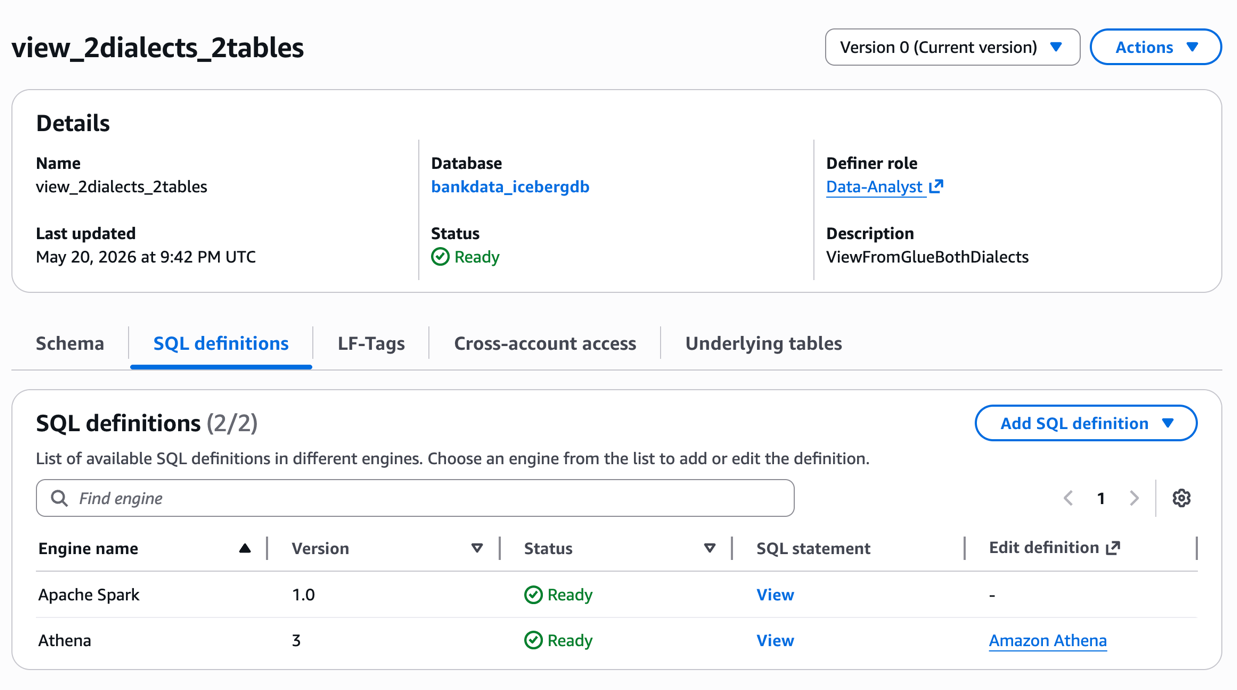
  5. After the view is created, you can inspect the details on the Lake Formation console. The SQL definitions show both ATHENA and SPARK as shown in the following screenshot.

Lake Formation console showing the SQL definitions tab for the new Data Catalog view, with both ATHENA and SPARK dialects listed

If your view creation fails for any of the dialects, you can use the AWS Glue get-table CLI command with --include-status-details to see what the error is and rectify it.

aws glue get-table --database-name <rl_database_name> --name <view_name> --include-status-details

Glue PySpark script

The PySpark script for creating a view with ATHENA and SPARK dialects are provided below. Download and edit the Pyspark script with your bucket name, producer and central account ids, region and relevant Glue resource names: bdb_5773_createview_bothdialects.py

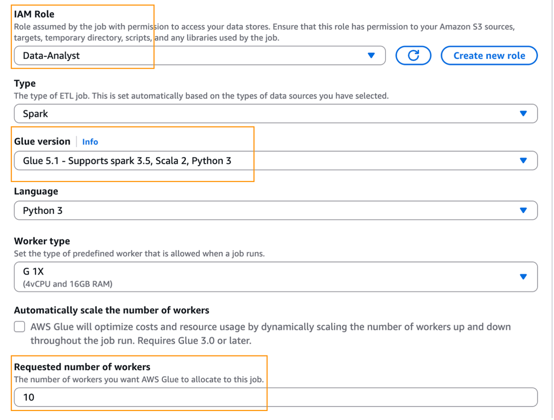
Provide the following settings to run the script in your Glue Studio. For details on running a Spark job in Glue, refer Working with Spark jobs in AWS Glue.

  • Choose Data-Analyst as the job execution IAM role.
  • Choose Glue 5.1 for Glue version.
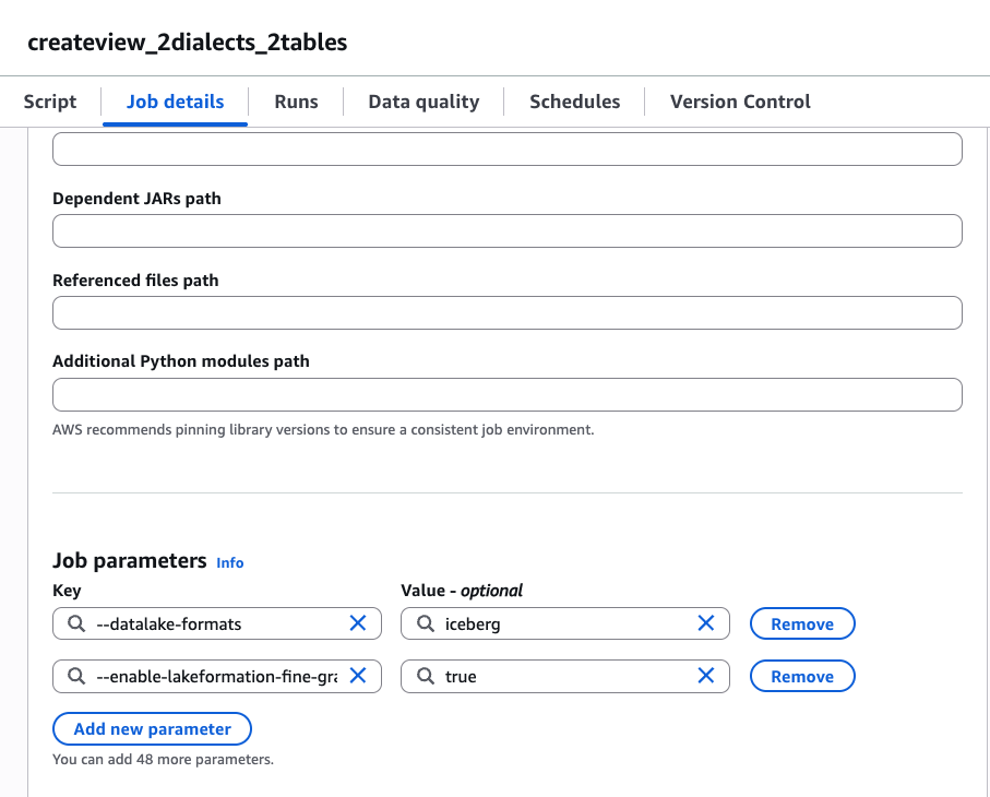
  • For the Requested number of workers, provide >=4. This is an FGAC Spark driver requirement, which is needed for Glue catalog views. Below screenshot shows these settings.
  • Add the following 2 properties as additional job parameters. A screenshot is shown for reference.
    --datalake-formats = iceberg
    --enable-lakeformation-fine-grained-access=true

    AWS Glue ETL job configuration page showing the additional job parameters set for the multi-dialect view creation script

  • Save and run the Glue job. Check the stdout logs to review the query on the newly created view.

A sample update_table script is also provided below, to illustrate changing the view definition with additional columns. Note the REPLACE keyword:

bdb_5773_updateview_bothdialects.py

Adding ATHENA dialect using SDK to an existing AWS Glue view

You can update an existing AWS Glue view that was created with the SPARK dialect and add the ATHENA dialect using the SDK. The following example uses the update-table CLI command.

aws glue update-table --cli-input-json file://add-athena-dialect.json

The content of add-athena-dialect.json is as follows.

{
    "DatabaseName": "rl_bank_iceberg",
    "ViewUpdateAction": "ADD",
    "TableInput": {
        "Name": "view_sparkfirst_athenanext",
        "ViewDefinition": {
            "Representations": [
                {
                    "Dialect": "ATHENA",
                    "DialectVersion": "3",
                    "ViewOriginalText": "SELECT a.transaction_id, a.transaction_type, a.transaction_amount, b.transaction_location, b.transaction_date FROM bankdata_icebergdb.transaction_table1 a RIGHT JOIN bankdata_icebergdb.transaction_table2 b ON a.transaction_id = b.transaction_id",
                    "ValidationConnection": "glue-view-validation-connection"
                }
            ]
        }
    }
}

Verify the added dialect on the view by reviewing the SQL definitions of the view in Lake Formation console or using GetTable(). If you want to edit the SQL definition or change the base tables of an existing view that has both SPARK and ATHENA dialects, you can do so using the update_table API (using SDK or CLI), with "ViewUpdateAction": “REPLACE” and provide both the dialect definition under ViewDefinition.

You can run queries on the view from the producer account as Data-Analyst. The view can be shared using Lake Formation Tags or named method, just like sharing tables, to additional consumer accounts from the central governance account. The consumer accounts will create a resource link and query the views.

Cleanup

To avoid incurring ongoing costs, clean up the resources you used for this post:

  1. Revoke the Lake Formation permissions granted to the Data-Analyst role and the producer account from the central governance account.
  2. Drop the Data Catalog tables, views, and the database.
  3. Delete the Athena query results from your Amazon Simple Storage Service (Amazon S3) bucket.
  4. Delete the Data-Analyst role from IAM.
  5. Delete the AWS Glue connection and the Athena data source.
  6. Delete the AWS Glue job, if you tried the Python script as an AWS Glue job.

Conclusion

In this post, I demonstrated how to use cross-account IAM definer roles with AWS Glue Data Catalog views, how to create and update ATHENA and SPARK dialects using the Data Catalog CreateTable() and UpdateTable() APIs. The multi-dialect Data Catalog views allow sharing a subset of data from different tables using Lake Formation permissions, including LF-Tags based access control. The cross-account definer roles support multi-account data mesh architectures so that the producer IAM roles can run the CI/CD pipelines in its account. We encourage you to try the feature and share your feedback in the comments.

Acknowledgements: I would like to thank all the team members who worked to add AWS SDK support for creating ATHENA and SPARK dialects together for AWS Glue views – Daniil Arushanov, Wyatt Hawes, Yuxi Wu, Santhosh Padmanabhan and Karthik Devaraj.


About the author

Aarthi Srinivasan

Aarthi Srinivasan

Aarthi is a Senior Big Data Architect working on data, analytics and GenAI topics with the worldwide Specialists Org at AWS. She works with AWS customers and partners to architect data lake solutions, enhance product features, and establish best practices for data governance and analytics services adoption.

Zero Copy access to Apache Iceberg tables in Amazon S3 from Salesforce Data 360 using the Iceberg REST endpoint from AWS Glue Data Catalog

Post Syndicated from Avijit Goswami original https://aws.amazon.com/blogs/big-data/zero-copy-access-to-apache-iceberg-tables-in-amazon-s3-from-salesforce-data-360-using-the-iceberg-rest-endpoint-from-aws-glue-data-catalog/

Companies increasingly need to query and analyze data across platforms without the cost and complexity of moving it. Salesforce and AWS have collaborated to make this possible by providing Zero Copy access to Apache Iceberg tables stored in Amazon Simple Storage Service (Amazon S3) directly from Salesforce Data 360, using the Iceberg REST endpoint from AWS Glue Data Catalog with data access managed by AWS Lake Formation. This integration helps customers federate their Amazon S3 data lakes with Data 360, preserving data governance, freshness, and business semantics without replication.

Zero Copy file federation plays an important role in activating applications and experiences. By removing the need to physically move or copy data, and connecting to data at the storage level, it addresses key challenges including:

  • Cost efficiency – Reduce storage duplication costs and minimize the compute resources required for data pipelines.
  • High scale – Access data with near-native performance at scale through in-Region access.
  • Enhanced agility – Access and analyze data in real time, accelerating time-to-insight and supporting faster response to evolving business needs.
  • Streamlined operations – Remove the complexity of building and maintaining intricate data pipelines, clearing up valuable data engineering resources.

In this post, we demonstrate how AWS and Salesforce customers can access their enterprise data lakes on AWS from Data 360 using Zero Copy file federation.

What is Data 360?

Data 360 is the real-time data engine that activates trusted context across the entire Salesforce platform. It connects all your enterprise data — data warehouses, data lakes, third-party signals, and more — to the business context, logic, and governance that already live in Salesforce, without moving or copying it. With Zero Copy federation, your teams and AI agents always operate from a complete, current, and trusted picture of your business in the moment it’s needed. It serves as the essential system of context for Agentforce, enabling agents to reliably get real work done.

What is Apache Iceberg?

Apache Iceberg is a high-performance, open table format for huge analytic datasets that brings the reliability and simplicity of SQL tables to big data. It’s a thriving open source project under the Apache Software Foundation. Data engineers use Apache Iceberg because it’s fast, efficient, and reliable at any scale and keeps records of how datasets change over time. Apache Iceberg offers integrations with popular data processing frameworks such as Apache Spark, Apache Flink, Apache Hive, Presto, and more.

Why Amazon S3 for Apache Iceberg data lakes?

Amazon S3 is regarded as the best place to build data lakes because of its durability, availability, scalability, security, compliance, and audit capabilities, and its ability to integrate with a broad portfolio of AWS and third-party tools for data ingestion and processing. Apache Iceberg was designed and built to interact with Amazon S3, and provides support for many Amazon S3 features as listed in the Iceberg documentation.

What is Zero Copy file federation?

File federation, also termed catalog federation, uses the Data Catalog to communicate with remote catalog systems to discover catalog objects and to authorize access to their data in Amazon S3. When you query a remote Iceberg table, the Data Catalog discovers the latest table information in the remote catalog at query runtime, getting the table’s Amazon S3 location, current schema, and partition information. Your analytics engine then uses this information to access Iceberg data files directly from Amazon S3, and Lake Formation manages access to the table and data by vending scoped credentials to the table data stored in Amazon S3. This approach avoids metadata and data duplication while providing real-time access to remote Iceberg tables through your preferred AWS analytics engines.

Solution overview

Apache Iceberg file federation lets Data 360 directly query data stored in Amazon S3 without copying or moving the data. This Zero Copy approach provides several benefits:

  • Real-time access to Amazon S3 data from Salesforce.
  • Reduced data movement and storage costs.
  • Simplified data architecture.
  • Improved data freshness.

The following diagram illustrates the architecture of the integration between Data 360 and Amazon S3 using Apache Iceberg file federation.

Key components:

  1. Amazon S3 stores the source data in Apache Iceberg format.
  2. AWS Glue Data Catalog maintains the metadata for Iceberg tables.
  3. AWS Glue Iceberg REST endpoint provides RESTful access to Iceberg tables.
  4. AWS Lake Formation manages metadata and underlying data access for Amazon S3-based data lakes.
  5. Data 360 processes and analyzes the data.
  6. Apache Iceberg connector provides direct access to query Amazon S3 data from Salesforce.

Walkthrough

The following walkthrough shows you how to set up Zero Copy file federation.

Prerequisites

Before you begin, you need the following:

Configure your AWS environment

Set up an Amazon S3 bucket and Iceberg table

Sign in as the data lake admin and complete the following steps:

  1. Open the Amazon S3 console.
  2. Choose Create bucket to create a bucket.
  3. For Bucket type, choose General purpose, provide a Bucket name, and choose Create bucket.
  4. In the bucket, create two prefixes by choosing Create folder.
  5. Name the prefixes athena_iceberg and athena_results.
  6. Inside the athena_iceberg prefix, create another prefix named customer_iceberg.

Create an Iceberg table using Athena

  1. Open the Amazon Athena console.
  2. Choose Query your data in Athena console, then choose Launch query editor.
  3. In Athena, choose Edit settings.
  4. Set s3://<your-bucket-name>/athena_results/ as the Location of query result, then choose Save. Replace <your-bucket-name> with your bucket name.
  5. Choose Editor to return to the query editor page.
  6. To create the database, copy the following query into the query editor and choose Run. You need to be in the Athena Query Editor to run the following commands.
    create database iceberg_db;

  7. To create the Iceberg table, copy the following query into the query editor, replace <s3 bucket location> with your Amazon S3 bucket location hosting the Iceberg table, and choose Run.
    CREATE TABLE iceberg_db.churn (
        state string,
        account_length int,
        area_code string,
        phone string,
        intl_plan string,
        vmail_plan string,
        vmail_message int,
        day_mins double,
        day_calls int,
        day_charge double,
        eve_mins double,
        eve_calls int,
        eve_charge double,
        night_mins double,
        night_calls int,
        night_charge double,
        intl_mins double,
        intl_calls int,
        intl_charge double,
        custserv_calls int,
        churn boolean)
    LOCATION 's3://<s3 bucket location>/iceberg/churn'
    TBLPROPERTIES (
        'table_type'='iceberg',
        'compression_level'='3',
        'format'='PARQUET',
        'write_compression'='ZSTD'
    );

  8. Insert some records into the table.
    -- Sample data insert for "iceberg_db"."churn"
    -- Execute this in the Athena console
    INSERT INTO "iceberg_db"."churn" VALUES
    ('KS', 128, '415', '382-4657', 'no', 'yes', 25, 265.1, 110, 45.07, 197.4, 99, 16.78, 244.7, 91, 11.01, 10.0, 3, 2.70, 1, false),
    ('OH', 107, '415', '371-7191', 'no', 'yes', 26, 161.6, 123, 27.47, 195.5, 103, 16.62, 254.4, 103, 11.45, 13.7, 3, 3.70, 1, false),
    ('NJ', 137, '415', '358-1921', 'no', 'no', 0, 243.4, 114, 41.38, 121.2, 110, 10.30, 162.6, 104, 7.32, 12.2, 5, 3.29, 0, false),
    ('OH', 84, '408', '375-9999', 'yes', 'no', 0, 299.4, 71, 50.90, 61.9, 88, 5.26, 196.9, 89, 8.86, 6.6, 7, 1.78, 2, false),
    ('OK', 75, '415', '330-6626', 'yes', 'no', 0, 166.7, 113, 28.34, 148.3, 122, 12.61, 186.9, 121, 8.41, 10.1, 3, 2.73, 3, false),
    ('AL', 118, '510', '391-8027', 'yes', 'no', 0, 223.4, 98, 37.98, 220.6, 101, 18.75, 203.9, 118, 9.18, 6.3, 6, 1.70, 0, false),
    ('MA', 121, '510', '355-9993', 'no', 'yes', 24, 218.2, 88, 37.09, 348.5, 108, 29.62, 212.6, 118, 9.57, 7.5, 7, 2.03, 3, false),
    ('MO', 147, '415', '329-9001', 'yes', 'no', 0, 157.0, 79, 26.69, 103.1, 94, 8.76, 211.8, 96, 9.53, 7.1, 4, 1.92, 0, false),
    ('WV', 141, '415', '330-8173', 'yes', 'yes', 37, 258.6, 84, 43.96, 222.0, 111, 18.87, 326.4, 97, 14.69, 11.2, 5, 3.02, 0, false),
    ('IN', 65, '415', '329-6603', 'no', 'no', 0, 129.1, 137, 21.95, 228.5, 83, 19.42, 208.8, 111, 9.40, 12.7, 6, 3.43, 4, true),
    ('RI', 74, '415', '344-9230', 'no', 'no', 0, 187.7, 127, 31.91, 163.4, 148, 13.89, 196.0, 94, 8.82, 9.1, 5, 2.46, 0, false),
    ('IA', 168, '408', '363-1107', 'no', 'no', 0, 275.8, 90, 46.89, 230.0, 73, 19.55, 191.3, 57, 8.61, 9.9, 3, 2.67, 4, true),
    ('MT', 95, '510', '394-8006', 'no', 'no', 0, 113.2, 96, 19.24, 269.9, 107, 22.94, 229.1, 87, 10.31, 7.1, 4, 1.92, 1, false),
    ('NY', 62, '415', '371-5765', 'no', 'no', 0, 236.5, 127, 40.21, 145.3, 101, 12.35, 225.0, 103, 10.13, 12.0, 1, 3.24, 5, true),
    ('TX', 109, '408', '356-2992', 'no', 'yes', 33, 190.7, 114, 32.42, 218.2, 111, 18.55, 156.5, 122, 7.04, 11.6, 5, 3.13, 1, false),
    ('CA', 155, '510', '328-8230', 'no', 'no', 0, 197.3, 78, 33.54, 160.2, 86, 13.62, 280.1, 90, 12.60, 8.8, 2, 2.38, 2, false),
    ('WA', 132, '415', '382-1011', 'yes', 'no', 0, 302.7, 67, 51.46, 212.0, 105, 18.02, 265.5, 82, 11.95, 10.3, 4, 2.78, 3, true),
    ('FL', 88, '408', '344-5678', 'no', 'yes', 18, 145.3, 95, 24.70, 187.6, 92, 15.95, 198.2, 108, 8.92, 9.4, 3, 2.54, 0, false),
    ('CO', 201, '510', '367-4321', 'no', 'no', 0, 312.5, 142, 53.13, 178.9, 76, 15.21, 145.7, 95, 6.56, 14.2, 8, 3.83, 6, true),
    ('GA', 56, '415', '390-2244', 'no', 'yes', 12, 178.4, 101, 30.33, 205.1, 119, 17.43, 230.8, 100, 10.39, 8.0, 2, 2.16, 1, false);

Register the bucket with Lake Formation in Lake Formation mode

To use Lake Formation permissions for access control to the churn table, you must register the location. To do that, complete the following actions:

  1. Open the AWS Lake Formation console.
  2. In the navigation pane under Administration, choose Data lake locations.
  3. Choose Register location and enter the following information:
    1. For S3 URI, enter s3://<s3 bucket location>/iceberg/churn. Replace <s3 bucket location> with your Amazon S3 bucket location hosting the Iceberg table.
    2. For IAM role, choose the user-defined IAM role that you created in the prerequisites.
    3. For Permission mode, choose Lake Formation.
  4. Choose Register location.

Enable third-party integration in Lake Formation

From the Lake Formation console, enable full table access for external engines.

  1. Open the AWS Lake Formation console.
  2. On the left pane, expand the Administration section.
  3. Choose Application integration settings and select Allow external engines to access data in Amazon S3 locations with full table access.
  4. Choose Save.

Application integration settings page in the Lake Formation console with full table access enabled for external engines

Set up an IAM user for third-party access

  1. Open the IAM console.
  2. From the left navigation menu, choose Policies, then choose Create policy. Choose JSON and paste the following policy:
    {
        "Version": "2012-10-17",
        "Statement": [
            {
                "Sid": "VisualEditor0",
                "Effect": "Allow",
                "Action": "lakeformation:GetDataAccess",
                "Resource": "*"
            }
        ]
    }

  3. Choose next, provide a name for the policy, and choose Create policy.
  4. From the left navigation menu, choose Users, then choose Create user.
  5. For username, enter data_cloud_user, choose next, and choose Attach policies directly.
  6. Choose AWSGlueServiceRole and the policy that you created in step 3. Choose next and Create user.
  7. Choose the user, then choose Security credentials to create an access key.
  8. Scroll down and choose Create access key, choose Applications running outside AWS, and choose Create access key.
  9. Copy the access key and secret access key, and save them securely. You need these to configure the connector in Data 360.

Set up Lake Formation resource permissions for third-party data access

  1. Open the Lake Formation console.
  2. From the left navigation under Data Catalog, choose Databases, then choose the athena_iceberg_db database.
  3. From the Actions menu, choose Permissions, Grant.
  4. In Principals, choose IAM users and roles, and from the menu choose data_cloud_user, which you just created in IAM.
  5. Scroll down to grant permissions by choosing All tables, then choose Select and Describe permissions for the tables.
  6. Choose Grant to apply the permissions.

Set up Apache Iceberg file federation in Data 360

Create and configure the connection

  1. Navigate to Salesforce Setup. For instructions, see Set Up the AWS Glue Data Catalog Connection.
  2. In Data Cloud, choose Setup, then choose Data Cloud Setup.
    Data Cloud Setup page in Salesforce showing options to configure connections
  3. Under External Integrations, choose Other Connectors.
  4. Choose New.
  5. On the Source tab, choose AWS Glue Data Catalog, then choose Next.
    New connector page in Salesforce Data Cloud with AWS Glue Data Catalog selected as the source
  6. Complete the following information shown in the following screen:
    1. In the Authentication Details section, enter the AWS access key ID and AWS secret access key for the IAM user. Make sure that the IAM user has a policy that grants the user read-only access to AWS Glue Data Catalog. Use Lake Formation to configure storage credential vending. This approach is for AWS Glue Data Catalog to vend temporary credentials at run time so that Data 360 can access the underlying storage bucket.
    2. For Catalog URL, enter the URL of AWS Glue Data Catalog. See Connecting to the Data Catalog by using AWS Glue Iceberg REST endpoint.
    3. For Catalog ID, enter the 12-digit AWS account ID linked to AWS Glue Data Catalog.
    4. For Signing Region, enter the host AWS Region where AWS Glue Data Catalog is located.
    5. For Signing Service, enter glue. Data 360 requires the Signing Service, in addition to the AWS access key ID, secret access key, and Signing Region, to sign requests to AWS Glue Data Catalog by using AWS Signature Version 4.
    6. Test the connection and check for the success message.
    7. Save the connection details.

    AWS Glue Data Catalog connection configuration form in Salesforce Data Cloud showing authentication details, catalog URL, catalog ID, signing Region, and signing service fields

  7. After the configuration is complete and saved, the new AWS Glue Data Catalog connection shows up with “Active” status in the Connectors screen.Connectors screen in Salesforce Data Cloud showing the new AWS Glue Data Catalog connection with Active status

Create and configure the data stream

  1. In Data Cloud, on the Data Streams tab, choose New.
  2. Under Other Sources, choose the AWS Glue Data Catalog source, then choose Next.
  3. From the menus, choose the connection that you just set up, choose a database in your AWS Glue catalog where you have an Iceberg table, choose the table that you want to stream, and choose Next.Data stream configuration page showing AWS Glue Data Catalog source with connection, database, and Iceberg table selection menus
  4. Enter the object name and object API name. For more information, see Data Lake Object Naming Standards.
  5. Choose the category to specify the type of data to ingest. For more information, see Category.
  6. Choose a primary key to uniquely identify the incoming records. For more information, see Primary Key.
  7. Choose the source fields you want to ingest, then choose Next. Fields with convertible data types are listed under Supported Fields.Source fields selection page showing supported fields for the Iceberg table data stream
  8. Choose the relevant data space. Choose “Default” if you don’t have any other data space provisioned in your org. For more information, see Data Spaces.
  9. Choose Deploy.
    Data stream deployment confirmation page in Salesforce Data Cloud
  10. After the setup is complete, the new data stream appears in your Data Cloud environment.
    Data Cloud environment showing the newly deployed data stream for the Iceberg table
  11. The data stream is ready. You can now go to the Data Explorer in your Data Cloud environment and start viewing the Iceberg tables that reside in your external AWS account.Data Explorer in Salesforce Data Cloud showing Iceberg tables from the external AWS account

Best practices and considerations

  • Use IAM roles with least-privilege access. Grant only the specific permissions each service or user needs.
  • Implement appropriate Amazon S3 bucket policies. Define bucket-level policies that restrict access by AWS account, VPC endpoint, or IP range.
  • Monitor access patterns. Enable Amazon S3 server access logging or AWS CloudTrail data events to track who reads from and writes to your table buckets.
  • Optimize Iceberg table partitioning. Choose partition keys that align with your most common query filters.
  • Consider data access patterns. Design your table layout around how data is actually queried.
  • Implement lifecycle policies for Amazon S3 objects. Configure Amazon S3 lifecycle rules to transition older data files to other storage classes.
  • Use appropriate Iceberg file compaction strategies. Run compaction regularly to merge small files produced by streaming or frequent batch appends.
  • Monitor data transfer costs. Track cross-Region and internet egress charges using AWS Cost Explorer as applicable.

Clean up

After you finish testing, clean up all the resources in your AWS account that you created (including the Amazon S3 bucket, Athena tables, and other AWS services) to avoid recurring costs.

Conclusion

By implementing Apache Iceberg file federation between Data 360 and Amazon S3, you can create a more efficient and streamlined data architecture. This solution gives you real-time access to Amazon S3 data while using the analytics capabilities of Data 360. As businesses continue to prioritize data-driven decision-making, Zero Copy data sharing plays an important role in unlocking the full potential of customer data across platforms.

To learn more, review the following resources:


About the authors

Avijit Goswami

Avijit Goswami

Avijit is a principal specialist solutions architect at AWS specializing in data and analytics. He helps customers design and implement robust data lake solutions. Outside the office, you can find Avijit exploring new trails, discovering new destinations, cheering on his favorite teams, enjoying music, or testing out new recipes in the kitchen.

Srividya Parthasarathy

Srividya Parthasarathy

Srividya is a Senior Big Data Architect on the AWS Lake Formation team. She works with the product team and customers to build robust features and solutions for their analytical data platform. She enjoys building data mesh solutions and sharing them with the community.

Pratik Das

Pratik Das

Pratik is a Senior Product Manager with AWS Lake Formation. He is passionate about all things data and works with customers to understand their requirements and build delightful experiences. He has a background in building data-driven solutions and machine learning systems

Bill Tarr

Bill Tarr

From software builder to architecture, Bill has 20+ years of experience shaping best-in-class SaaS technology strategies for organizations from startup to enterprise. He’s also an AWS SaaS community leader and a producer of the “Building SaaS on AWS” show on twitch.com/aws, as well as an experienced public speaker with experience at top tier AWS events such as re:Invent, and publisher of SaaS best practices.

Multi-cloud lakehouse architecture on AWS for Agentic AI, Part 1: Architecture and best practices

Post Syndicated from Sakti Mishra original https://aws.amazon.com/blogs/big-data/multi-cloud-lakehouse-architecture-on-aws-for-agentic-ai-part-1-architecture-and-best-practices/

Enterprise data architectures have become fundamentally distributed. Over the past decade, organizations have made deliberate investments across multiple platforms such as relational databases for transactional workloads, cloud data warehouses for analytics, object stores for unstructured data, and SaaS applications for domain-specific functions. Each was chosen to solve a specific problem, serve a specific team, or meet a specific performance requirement. The result is not accidental sprawl. It is a deeply heterogeneous data landscape shaped by intentional, workload-driven decisions. The challenge now is not consolidation, but interoperability: enabling these systems to function as a unified foundation for the next generation of AI-driven applications.

Agentic AI systems that autonomously reason, plan, and take action on behalf of users are moving rapidly from experimentation to enterprise production. These systems do not just retrieve information. They synthesize it, act on it, and learn from it. And unlike traditional analytics tools that can work with a well-scoped dataset, AI agents require something more demanding: unified, governed, and real-time access to all relevant enterprise data, regardless of where it lives.

This is the gap that matters most right now. Enterprises that have invested in building strong data capabilities across multiple providers are well-positioned, but only if those platforms can be accessed together, consistently, and with the governance controls that enterprise AI requires. Without a unified data foundation, AI agents operate with incomplete context, governance becomes inconsistent, and the promise of autonomous AI remains out of reach.

Solution approach

The following high-level architecture explains how you can onboard metadata catalogs and MCP servers to your context layer, which becomes the primary input for your AI agents.

Assuming your data products have a well-defined metadata catalog, you can take a unified-catalog-first approach, then build the context layer on top of it to let your AI agents discover all the context from one place. This helps bring in centralized governance and audit control, because every request gets routed through the centralized metadata catalog and context layer to simplify implementation of unified governance. In addition, this brings simplicity to enable business semantics, define attribute priorities, and define authoritative sources for the consumer use cases.

Architecture showing metadata catalogs and MCP servers onboarded to a context layer that feeds AI agents

If any of the data sources does not have a well-defined metadata catalog, you can define Model Context Protocol (MCP) servers on them, and then directly onboard them to the context layer. For example, if you have semi-structured or unstructured datasets for which you do not have a well-defined metadata catalog, or you want to onboard third-party data sources through REST APIs, then you can add their respective MCP server to the context layer directly. The following architecture explains the extended flow for it.

Extended architecture where data sources without a metadata catalog expose MCP servers directly to the context layer

In this series of posts, we demonstrate how you can unify the metadata catalog access across multiple providers, how you can enable AI agents to query the unified catalog, and how the context layer can be integrated to unify metadata from catalogs and MCP servers. We have divided the series into the following parts.

  • Part 1: Architecture approach with tradeoffs to unify a multi-cloud lakehouse architecture that can power Agentic AI (this post).
  • Part 2: Implementing an example solution to unify catalogs from multiple providers and deploy AI agents to query the unified data access layer.
  • Part 3: Integrate a context layer on top of the unified catalog for AI agents.
  • Part 4: Onboard additional data sources to the context layer through MCP servers and demonstrate the full solution.

This post focuses on explaining the architecture approach to build the open lakehouse architecture on AWS, unifying the metadata catalog across providers for the AI agents to access. In addition, it highlights the architecture trade-offs and best practices.

Use case

Every AI initiative launched on a fragmented data foundation is an initiative that will need to be rebuilt. Organizations that establish unified data access today are the ones that will scale Agentic AI with confidence tomorrow. Consider a large enterprise managing petabytes of data across a diverse set of environments:

  • On-premises: Network device telemetry, customer records, and operational databases.
  • Multiple cloud platforms: Marketing analytics, HR systems, and enterprise applications distributed across cloud providers.
  • Data platforms: Data science workloads, feature engineering pipelines, and finance and supply chain analytics running on specialized platforms.
  • SaaS applications: Salesforce, SAP, Zendesk, ITSM, and other business tools that each hold a critical piece of the enterprise data picture.

The business objective is to build a unified analytics and AI platform that can:

  • Query and analyze data across all environments without requiring full data migration.
  • Enforce consistent data governance and access control regardless of data location.
  • Power AI agents that can autonomously discover, query, and act on enterprise data.
  • Reduce total cost of ownership by eliminating redundant pipelines and storage.

This architecture directly addresses these needs by combining flexible data integration patterns, an open-table-format-based lakehouse architecture (with an example of Apache Iceberg), AI agent deployment to access unified metadata, and centralized governance.

Reference architecture

Before going deeper into a specific architecture, let’s revisit at a high level how the AWS open lakehouse architecture enables data ingestion and query or catalog federation to power analytics, machine learning development, and generative AI application development.

The following architecture diagram represents an end-to-end flow that includes:

  • Data ingestion to the data lake or data warehouse through Zero-ETL and batch or stream processing using AWS native services, or accessing data from Google Cloud Platform using AWS Interconnect – multicloud.
  • A centralized metadata catalog layer that includes data on AWS and metadata representation of non-AWS data sources using query or catalog federation.
  • A context layer that you can integrate to create a knowledge graph with ontology and business semantics that can enrich context for AI agents.
  • The consumption layer, which can include analytics, machine learning model development with Amazon SageMaker AI, and generative AI application development with Amazon Bedrock AgentCore, Amazon Quick, or other AWS and non-AWS AI applications.

End-to-end AWS open lakehouse architecture spanning ingestion, catalog, context, and consumption layers

Let’s look at an expanded version of this architecture that details the data ingestion and data consumption patterns to build a unified data access layer on AWS that spans multiple cloud and ISV providers.

Expanded technical architecture walkthrough

The following architecture demonstrates the comprehensive AWS approach for metadata catalog consolidation through flexible integration patterns, and it also highlights patterns for building a lakehouse on AWS. Built on the open standards of Apache Iceberg for storage and governance through AWS Lake Formation, it creates a unified data foundation that connects existing investments without requiring wholesale migration, and it makes enterprise data AI-ready from day one. This architecture delivers value at every layer: business teams query across platforms without data movement, IT teams manage governance through a single federated layer with the flexibility to federate or ingest per use case, and compliance teams enforce policies once across all sources with full lineage and audit coverage.

Expanded lakehouse architecture on AWS showing federation and ingestion patterns across multiple cloud and ISV providers

The following are the key components of the architecture.

Data access methods

This section provides options to access data that is not available in AWS Glue Data Catalog and not available on AWS.

1. Iceberg catalog federation (Reference points 2, 6.1, 6.2)

  • AWS Glue Data Catalog implements the Iceberg REST Catalog API specification, which enables seamless federation with Databricks, Snowflake, or other Iceberg-compatible catalogs set up with Amazon Simple Storage Service (Amazon S3) as the storage layer.
  • With the growing adoption of Apache Iceberg, catalog federation will become a common standard in the future and simplify metadata unification.

2. Query federation (Reference point 1.1)

  • Direct cross-cloud querying over the public internet to Google BigQuery, Azure SQL, Salesforce, and other platforms.
  • Real-time access to external data sources without replication, and seamless access with AWS analytics services.
  • Provides flexibility, because the catalog federation capability of the Iceberg REST catalog is limited to Iceberg tables only.

2.1. Secured private connectivity to Google Cloud Platform using AWS Interconnect for multi-cloud (Reference points 3.1, 3.2)

The default query federation approach makes the connection and transfers data over the public internet, which has its own latency implications depending on the target platform and the data volume transferred over the internet. During re:Invent 2025, AWS announced the public preview of AWS Interconnect – multicloud, which recently became generally available.

AWS Interconnect – multicloud is a managed service that provides private, high-speed, and secure network connections between Amazon Web Services (AWS) and other cloud providers, starting with Google Cloud Platform (GCP), with Microsoft Azure and Oracle Cloud Infrastructure (OCI) coming later in 2026. You can enable the integration with three steps: 1) specify the target cloud service provider, 2) select the destination Region on the other side, and 3) pick the required bandwidth.

The following architecture represents AWS and GCP integration with AWS Interconnect – multicloud.

High-level architecture of AWS and GCP integration through AWS Interconnect for multi-cloud

On the AWS side, you need an AWS Direct Connect gateway (a global construct that acts as a route reflector), which you can attach to your Amazon Virtual Private Cloud (Amazon VPC) through a virtual private gateway or AWS Transit Gateway, or AWS Cloud WAN. On the GCP side, you need a Google Cloud Router that you attach to your customer VPC. Interconnect – multicloud offers pre-cabled capacity pools at shared Interconnect points of presence (PoPs) in selected Regions, where both AWS and GCP routers are co-located and pre-wired.

Because Interconnect – multicloud primarily routes traffic within the VPC through a private network, to benefit from it you need to keep your query engine or jobs within a customer VPC.

2.2. High network bandwidth with on-premises systems (Reference point 4)

  • AWS Direct Connect for high-bandwidth, low-latency on-premises connectivity.

Data ingestion methods

This section focuses on ways you can use to onboard datasets (complete or subset) to a lakehouse on AWS.

1. Zero-ETL: Data movement to AWS with Zero-ETL ingestion (Reference points 5.1, 5.2)

  • AWS Zero-ETL capabilities for seamless data loading from AWS and non-AWS sources.
  • Flexibility to choose your target as an Amazon S3 based data lake or Amazon Redshift.

2. Extract, transform, load (ETL): Extract data from JDBC or SaaS sources and transform through a batch or stream pipeline (Reference points 3.1, 3.2)

The following architecture expands the flow 1.1 to 1.2 ingestion method that integrates AWS services to onboard data to the Amazon S3 raw layer and then takes it through an ETL pipeline for data cleansing and transformations. It also includes steps to onboard unstructured data to Amazon S3 using Amazon Bedrock Data Automation, and taking the lakehouse data for machine learning development with Amazon SageMaker AI.

Ingestion architecture integrating AWS services to load data into the Amazon S3 raw layer and process it through an ETL pipeline

You can also use AWS Interconnect – multicloud to run Spark jobs (Spark with Amazon EMR on EKS or open source Spark on any compute within a customer VPC) to ingest and transform data from Google Cloud with private connectivity.

3. Accessing data from Google Cloud over a private network

Refer to the preceding data access methods (3.1 and 3.2).

4. Onboarding data from AWS Outposts (S3 on Outposts) (Reference points 9.1 to 9.5)

  • Option to onboard S3 on AWS Outposts data to regional Amazon S3 through AWS DataSync (reference 9.1 to 9.3), which might be a better fit to sync files as-is through a scheduled batch or an event-driven approach.
  • Flexibility to transform the S3 on Outposts data using an Amazon EMR clusters on Outposts job, and then directly write the transformed output to a regional Amazon S3 bucket in the formats you want (including open table formats such as Apache Hudi, Apache Iceberg, and Delta Lake).

Lakehouse foundation with Apache Iceberg

By standardizing on Apache Iceberg, you’re not choosing AWS over your other platforms. You’re choosing interoperability and future flexibility. Your data becomes truly portable across any Iceberg-compatible engine.

  • Open table format: Industry-standard format supported across AWS, Databricks, Snowflake, and other platforms, which eliminates vendor lock-in.
  • ACID transactions: Reliability with full transactional consistency.
  • Time travel and schema evolution: Built-in versioning and flexible schema management.
  • Performance optimization: Advanced features such as hidden partitioning, partition evolution, and metadata management.

Note that lakehouse storage is not limited to the Apache Iceberg format, and you have the flexibility to include other open table formats (for example, Apache Hudi and Delta Lake) or file formats (for example, Apache Parquet and Apache Avro).

Unified governance and access control

AWS governance capabilities transform the lakehouse from a storage layer into a fully governed data platform. This delivers security, compliance, and data quality out of the box, applied consistently across all data sources including federated catalogs. A unified catalog consolidates metadata from AWS and non-AWS sources with generative AI-powered business glossary generation, while automated ML-powered classification identifies sensitive data (for example, PII, PHI, and financial data) across structured and unstructured datasets. AWS Identity and Access Management (AWS IAM) and AWS Lake Formation enforce fine-grained access control at the row, column, cell, and tag level, applied consistently across Amazon Athena, Amazon Redshift Spectrum, Amazon EMR, and federated sources. End-to-end data lineage tracking provides visual data flow graphs, impact analysis, and compliance audit trails. When AI agents explore metadata from the unified catalog and submit a query to Amazon Athena for execution, the Lake Formation fine-grained access control filters data based on the user interacting with the AI agent.

For the foundation model integrated into your AI agents, you can use Amazon Bedrock Guardrails, which implements customized safeguards to block harmful content and minimize hallucinations. Amazon Bedrock AgentCore provides fine-grained policy control over agent actions with real-time enforcement and managed authentication for agents accessing AWS and third-party services.

A comprehensive audit and compliance stack spans Amazon CloudWatch, AWS CloudTrail, AWS IAM, AWS Key Management Service (AWS KMS), AWS Audit Manager, and AWS PrivateLink. This stack makes sure every agent invocation is traceable, every key is managed, and every configuration is automatically mapped to frameworks including ISO, SOC, GDPR, and HIPAA.

When an end user interacts with the AI chat assistant, the layers of security and governance should go through the following.

Layer 1: Who can access?

  • Enable Active Directory and single sign-on integration for user authentication, and a combination of AWS IAM roles for AWS API-level authorization.

Layer 2: What can they see?

  • Integrate an agent profile to define what datasets each agent can access, because not all agents should have access to all datasets.
  • Enable fine-grained access control on the metadata layer using AWS Lake Formation that can filter rows and columns.
  • Enable data masking as applicable while the query responses are served through the query engine.

Layer 3: What can the agent do?

  • Control agent actions by restricting them to read-only, and apply restrictions to INSERT, UPDATE, and DELETE if the agents are supposed to query only.
  • Apply a limit on the number of rows that can be returned from the query, and apply a query scan limit to reduce cost.

Layer 4: What does the agent reveal?

  • Enable output filtering to make sure no PII is included.
  • Apply Amazon Bedrock Guardrails on large language model (LLM) responses to make sure the model does not produce anything inappropriate.
  • In addition, enable audit logging of all queries to make sure future audit and compliance needs can be met.

Comprehensive analytics ecosystem (Reference points 7.1, 7.2, 7.3)

AWS offers a complete analytics ecosystem that includes the following.

  • Amazon Athena: Serverless SQL queries with Iceberg v2 support, including provisioned capacity for consistent performance and workgroups for resource and cost management.
  • Amazon Redshift Spectrum: Federated queries across the data warehouse and Iceberg data lake.
  • Amazon Quick Sight: Enterprise visualization with governed access to all data.
  • AWS Glue and Amazon EMR: Distributed data processing capability for enterprise transformations.

AI-ready architecture (Reference points 8.1 to 8.4)

A consolidated lakehouse architecture helps you make data ready for AI agents that can access the data through readily available MCP servers or through the AWS SDK for Python (Boto3) for Amazon Athena or Amazon Redshift Spectrum. AI agents can integrate the AWS MCP Server to interact with AWS analytics services such as AWS Glue, Amazon Athena, and Amazon S3 Tables, a capability of Amazon S3, to query both data and metadata.

AI agents need context to understand how the catalog tables and their attributes are linked to each other, how users have queried them in the past, or what priorities are defined to understand which one is an authoritative source for a particular natural language question. To enable the AI agent with additional context, we can integrate the AWS Context service that was pre-announced recently at the AWS New York Summit 2026.

Governance integration: AI agents automatically inherit Lake Formation permissions, because the agent can submit the SQL query to be run through Amazon Athena or Amazon Redshift Spectrum. This makes sure they only access data that users are authorized to see. Amazon SageMaker Unified Studio data lineage tracks AI agent queries for full auditability.

The following diagram represents how the AI agent request flow looks.

AI agent request flow through the unified catalog, Lake Formation governance, and Amazon Athena

This architecture delivers value across every layer of the organization. Business teams gain faster time-to-insight by querying data across all platforms without waiting for data movement, while eliminating duplicate storage and reducing transfer costs through federation. The Apache Iceberg open table format ensures data portability and freedom from vendor lock-in. For IT and data teams, a single governance layer across all sources, including federated catalogs, reduces operational complexity, while the flexibility to choose between federation and ingestion for each use case, combined with the elastic AWS infrastructure and the petabyte-scale metadata architecture of Iceberg, delivers both agility and scalability. Data governance and compliance teams benefit from a single point of policy enforcement across all data regardless of location, complete lineage and access logs for audit and compliance reporting, automated sensitive data classification, and policies that are defined once and enforced everywhere, including across federated sources.

Architecture tradeoffs and best practices

The following are a few key trade-offs you need to consider while designing the solution.

Data ingestion and access methods

Use catalog federation (Iceberg REST) when:

  • The source platform supports the Iceberg REST API (Databricks, Snowflake Polaris).
  • Data is already in Iceberg format with Amazon S3 backed storage.
  • You want bidirectional discovery (AWS tables visible in Databricks or Snowflake too).

Use query federation (Amazon SageMaker Lakehouse architecture or AWS Glue connectors) when:

  • The source is BigQuery, SQL Server, or another non-Iceberg platform.
  • Data must stay in the source cloud (sovereignty, contractual, or latency reasons).
  • Real-time access is required without replication lag.

Use ingestion (Zero-ETL, AWS Glue, or Amazon EMR) when:

  • Data is accessed frequently with a low-latency requirement by AI agents or high-concurrency analytics.
  • The business decides to build a data lake and warehouse on AWS.
  • You need full governance, time travel, and performance optimization.

Use AWS Interconnect – multicloud when:

  • You need real-time or near-real-time query federation to GCP data sources (BigQuery, AlloyDB, Cloud Spanner) and latency or security requirements prohibit public internet routing.
  • You have high-volume, recurring data transfers between AWS and GCP where public internet egress costs or bandwidth variability are unacceptable.
  • Your organization has compliance or regulatory requirements mandating that data never traverse the public internet (HIPAA, PCI-DSS, or financial services regulations).
  • You need bidirectional connectivity, such as GCP workloads calling AWS APIs, or AWS workloads calling GCP APIs, both over private paths.

Choosing between federation and ingestion based on use case

Dimension Federation (Query in Place) Ingestion (Move to AWS)
Data freshness Real-time or near-real-time Dependent on ingestion frequency
Query performance Subject to source system latency and network Subject to data volume and operation, avoids cross-cloud network latency
Cost Lower storage cost. Higher per-query cost for cross-cloud egress Higher upfront ingestion cost. Lower ongoing query cost
Governance Partial. Source system retains some control, and a unified catalog can simplify governance for consumers Full. Lake Formation enforces all policies across all AWS analytics services
Data portability Data remains in source Data fully portable in open format
AI readiness Limited. Agents depend on source availability High. Agents query optimized, governed Iceberg tables
Operational complexity Lower initial setup. Harder to debug cross-cloud issues Higher initial setup. Simpler long-term operations

Integrating Amazon Bedrock AgentCore Gateway and Amazon Bedrock AgentCore Runtime based on use case

The following are key differences between AgentCore Gateway and AgentCore Runtime that are relevant for our use case.

Dimension Amazon Bedrock AgentCore Gateway Amazon Bedrock AgentCore Runtime
Timeout 5 minutes (hard limit) 15 min sync / 8 hours async
Statefulness Stateless (per-request) Stateful (session-based)
Best for Lightweight API proxying Long-running data processing
Your lakehouse queries Will time out frequently Handles multi-hour jobs

Because AgentCore Gateway has a 5-minute hard timeout limit, use AgentCore Runtime for data processing jobs.

  • AWS Glue ETL jobs can run for minutes to hours.
  • Amazon Redshift queries on large datasets routinely exceed 5 minutes.
  • Athena federated queries (especially cross-cloud through Interconnect) can be slow.
  • Iceberg table scans on multi-TB datasets take time.

You can use AgentCore Gateway if the scope is limited to Glue Data Catalog interactions to fetch metadata schema, because that won’t run for more than 5 minutes.

Design considerations for production implementation

In practice, there are multiple aspects to consider when deploying the solution for production. The following summarizes a few of the key issues you might encounter and approaches to address them.

Catalog federation: The metadata drift problem

One of the first surprises in production is metadata drift, the state where your federated catalog no longer reflects the actual schema of the source system, because the source system’s metadata changes are not reflected in the unified catalog. The agent continues to generate SQL against the stale schema, producing silent failures that are hard to trace.

The following are a few ways you can address the metadata drift issue.

  • Implement a catalog refresh schedule. Even a daily Glue crawler run against federated sources catches most drift before it causes agent failures.
  • Add schema validation as a pre-query step in your agent tool. Before running SQL, verify that the referenced columns exist in the current catalog metadata.
  • Instead of pulling metadata changes from the source in a scheduled manner, you can design an event-driven system, where the source system triggers a push event to run the schema change in the federated catalog.

Query federation: Latency is non-deterministic

Query federation works well for moderate data volumes, but latency becomes non-deterministic at scale. A query that returns in 3 seconds during testing can take more than 10 seconds in production when the source system is under load, the network path is congested, or the federated connector is cold-starting.

The following are a few approaches you can consider to improve the performance.

  • Set explicit query timeouts in your Athena execution context. Without them, a slow federated query will block your agent indefinitely.
  • Implement query result caching for frequently asked questions. Most business users ask the same questions repeatedly, and caching at the agent layer improves perceived performance.
  • For time-sensitive use cases, consider caching aggregated data in an AWS lakehouse on a schedule rather than querying live. This trades freshness for reliability.

AgentCore memory: Statefulness cost

AgentCore Memory enables stateful conversations, but in production, unbounded memory accumulation creates its own problems. An agent that remembers every conversation eventually starts surfacing stale context. For example, a user who asked about Q3 revenue six months ago gets that context injected into a Q1 query today.

The following are a few ways you can optimize cost and improve relevance.

  • Set explicit memory expiry (we use 30 days as shown in the implementation) and enforce it consistently.
  • Use session-scoped memory for transactional queries and long-term memory only for user preferences and recurring patterns.
  • Implement a memory review step in your LangGraph workflow. Before invoking the model, filter retrieved memories by recency and relevance score rather than injecting all of them.

LangGraph orchestration: When tool calls loop

The conditional routing of LangGraph is powerful, but in production we observed a failure mode where the agent enters a tool call loop. The model repeatedly calls the same tool with slightly different parameters, never reaching a satisfactory answer. This typically happens when the tool returns partial or ambiguous results and the model keeps trying to refine.

What we learned:

  • Add a maximum tool call counter in your LangGraph state. If the agent has called tools more than N times in a single session, force a graceful exit with a summary of what was found.
  • Return structured, unambiguous responses from your tools. Include row counts, column names, and explicit null indicators so the model can reason clearly about completeness.
  • Log every tool invocation with its input and output. This is the single most valuable debugging artifact when diagnosing agent misbehavior in production.

Handling hallucination risks in federated agent architectures

This is the most important section for teams moving from prototype to production. Hallucination in agentic AI systems that query real data is qualitatively different from hallucination in general-purpose LLMs, and it is more dangerous because the outputs look authoritative.

There are three distinct hallucination risk zones in a lakehouse AI agent:

  • SQL generation: The model generates SQL that is syntactically valid but semantically wrong. For example, when asked “What is our revenue growth this quarter?”, the model might generate a query that compares the wrong date ranges, uses the wrong aggregation function, or joins tables on incorrect keys, and then returns a confident, formatted answer with the wrong numbers.
  • Cross-source synthesis: When the agent queries multiple federated sources and synthesizes results, the risk compounds. The model may correctly retrieve customer counts from Amazon S3 and revenue figures from Snowflake, but incorrectly draw conclusions that aren’t supported by either dataset individually.
  • Memory-augmented reasoning: When long-term memory is active, the model may blend historical context with current query results in ways that are factually incorrect. For example, it might apply a business rule that was true six months ago but has since changed.

To improve, before any agent output informs a business decision, apply the following three-step validation framework:

  • Step 1: Source verification. Can you trace the answer back to a specific table, column, and row count? If the agent can’t show you the SQL and the row count, the answer is unverified.
  • Step 2: Reasonableness check. Does the answer fall within expected ranges? A sudden 10x spike in customer count is a signal to investigate.
  • Step 3: Cross-validation. For critical decisions, run the equivalent query directly in Athena or your BI tool and compare. Discrepancies reveal either a model reasoning error or a data quality issue. Resolve both before the answer is trusted.

These lessons don’t diminish the value of the architecture. They make it production-ready. The teams that move fastest with agentic AI are not the ones who skip these guardrails. They’re the ones who build them in from the start and spend less time firefighting in production.

Alternative to the unified catalog approach

In case you face technical and process challenges to unify catalogs across providers, you can let each data producer expose the metadata and data through MCP servers, as represented in the following diagram. In this approach, each producer takes the responsibility of maintaining the MCP servers and exposing them to the context layer. While this approach provides autonomy to data owners to operate independently and with flexibility, it also creates operational overhead to synchronize all metadata in a consistent way.

Alternative architecture where each data producer exposes its metadata and data through its own MCP server to the context layer

What’s next

In Part 2 of this series, we walk through the full implementation step by step, including hands-on scripts to:

  • Load example sales datasets into Databricks and marketing data to Snowflake as Iceberg tables, and federate them into AWS Glue Data Catalog through the Iceberg REST API.
  • Register Google BigQuery as a native federated data source in Amazon SageMaker, instead of a traditional AWS Lambda connector integration.
  • Create a customer master table as a native Iceberg table in Amazon S3.
  • Run a single SQL query in Amazon Athena that joins all four sources across two federation patterns, with no data movement.
  • Deploy an AI agent on Amazon Bedrock AgentCore that can autonomously query the same unified catalog using Amazon Athena and answer complex business questions in natural language queries. In addition, integrate AgentCore Memory to persist user context.

Conclusion

In this post, we summarized how you can unify data access across multiple cloud and ISV providers on AWS with the combination of catalog federation, query federation, and data movement to AWS. We then explained how AWS Glue Data Catalog and Lake Formation help provide unified catalog and access governance, and how AI agents hosted in Amazon Bedrock AgentCore can access it using MCP servers to explore the metadata context, convert user natural language queries to SQL, and use Amazon Athena to run the query across data sources to get the response to the end user. In addition, we provided an overview of different data ingestion methods to build a lakehouse architecture on AWS, including AWS Interconnect – multicloud and where it adds value.

We also provided architecture trade-offs and best practices to integrate the service capabilities. In the next post (Part 2), we will take a specific use case and provide a step-by-step implementation guide to unify the catalog and deploy the agent to Amazon Bedrock AgentCore.


About the author

Sakti Mishra

Sakti Mishra

Sakti is a Principal Data and AI Solutions Architect at AWS, where he helps customers modernize their data architecture and define end-to-end data strategies, including data security, accessibility, governance, and more. He is also the author of Simplify Big Data Analytics with Amazon EMR and AWS Certified Data Engineer Study Guide. Outside of work, Sakti enjoys learning new technologies, watching movies, and visiting places with family. You can connect with Sakti through his LinkedIn profile.

How BigBasket uses the Iceberg based lakehouse architecture on AWS to power lightning-fast grocery delivery across India

Post Syndicated from Annie Mattoo original https://aws.amazon.com/blogs/big-data/how-bigbasket-uses-the-iceberg-based-lakehouse-architecture-on-aws-to-power-lightning-fast-grocery-delivery-across-india/

Delivering fresh groceries to millions of customers across India in a few minutes demands a radically modern data architecture and resilient processes to help the business make faster decisions. This is what BigBasket was able to achieve by building a lakehouse architecture on AWS.

In this post, we demonstrate how BigBasket implemented the lakehouse architecture on AWS, including their architecture decisions, implementation approach, and the measurable business results you can expect from a similar modernization. Whether you’re facing scalability challenges or planning your own lakehouse implementation, this blueprint provides actionable insights you can adapt for your organization.

About BigBasket

BigBasket (Innovative Retail Concepts Private Limited) is India’s largest online supermarket, serving millions of customers across over 60 cities. Founded in 2011, the company offers groceries, fresh produce, household items, and personal care products through its mobile app and website, operating subscription services (BBDaily) and quick commerce (bbnow). For BigBasket, the ability to deliver groceries on time isn’t only a competitive advantage. It’s the foundation of customer trust, where every minute counts.

However, rapid business growth brought significant operational challenges:

  • Inability to consistently meet on-time delivery adherence because of high order volumes, extended travel times, and more, directly impacting key metrics like on-time rate (OTR)-10 mins and OTR-15 mins.
  • Struggling to meet on-time delivery targets because of picking inefficiency, high order volumes, and extended travel times, directly impacting key metrics like OTR-10 mins and OTR-15 mins.
  • Delays in stock availability impacting vendor fill-rates, inter-distribution center orders, and warehouse operations.
  • Inaccurate stock forecasting for top-selling stock keeping units (SKUs), assortment variety, event SKUs, store capacity, and buying cycles.
  • Lower dark store productivity across picking, stacking, order processing, and goods receipt notes (GRN).

Behind these business challenges lay a fundamental technology problem: the existing data infrastructure couldn’t keep pace. The company experienced rapid store growth, expanding 4x in a short timeframe, which exposed several limitations within their existing data architecture that needed attention.

Understanding the technical bottlenecks

BigBasket’s initial architecture relied heavily on a single data warehouse built on Amazon Redshift to meet all reporting and dashboarding needs. While this traditional approach had served them well initially, several important limitations emerged:

  • Stale data: Extract, transform, load (ETL) pipelines delivered only day-old (D-1) data, making near real-time analysis impossible for dashboard requirements.
  • Extended recovery times: Pipeline failure recovery processes took several hours, causing significant delays in data availability for business users.
  • Schema rigidity: Schema changes in source databases frequently triggered pipeline failures because of a lack of schema evolution support.
  • Scalability constraints: The infrastructure struggled to handle the sudden load increase from 13,000 to over 35,000 transactions for reports and dashboards with more than 1,000 dataset refreshes.
  • Cost implications: Increasing data volumes demanded additional compute resources, driving up costs.

Diagram of the scalability and cost limitations of BigBasket’s legacy Amazon Redshift data warehouse

It became clear that the existing data infrastructure wasn’t able to meet the evolving business requirements and a redesign of their data architecture is needed.

Why lakehouse architecture?

A modern data lakehouse architecture addresses these issues with near real-time data processing, flexible schema evolution, and scalable analytics, capabilities necessary for fast-moving commerce operations. The lakehouse approach combines the flexibility and cost-effectiveness of data lakes with the performance and governance features of data warehouses, combining the strengths of both. The design of a data lakehouse provides interoperability across storage systems for combined analytics activities.

Solution overview

BigBasket partnered with AWS to implement a comprehensive lakehouse architecture using a combination of AWS native services and open-source technologies.

The following diagram shows an elaborated view of Bigbasket’s modernized architecture on AWS.

Detailed lakehouse data flow across bronze, silver, and gold medallion layers on AWS

Data ingestion: Enabling continuous replication

AWS Database Migration Service (AWS DMS) ingests data from online transaction processing (OLTP) databases running on Amazon Relational Database Service (Amazon RDS) into the lakehouse on AWS.

This method continuously replicates data with minimal latency, so your analytics reflect near real-time business operations.

Storage and governance: Building a solid foundation

The lakehouse is built on Amazon Simple Storage Service (Amazon S3) and Amazon Redshift, which serve as the centralized data lake and warehouse following a medallion architecture.

The architecture persists all analytical data using Apache Iceberg as the open table format. Iceberg provides a robust foundation for large-scale analytics with the following capabilities:

  • ACID transactions: Guarantees data consistency and correctness across concurrent read and write operations.
  • Time travel: Supports querying historical table versions for auditing, troubleshooting, and recovery.
  • Schema evolution: Allows schema changes without disrupting existing queries or downstream pipelines.

The medallion architecture structures data across three logical layers within the lakehouse:

  • Bronze layer: Implements change data capture (CDC)-based source replication using AWS DMS. Raw change events flow into Amazon S3 as Apache Parquet files in their original format from source systems, preserving the complete change history. The data pipeline processes and deduplicates these events using Apache Spark on Amazon EMR to create and maintain Apache Iceberg tables that act as replicated source tables.
  • Silver layer: Represents the conformed data model, where data is cleansed, standardized, and validated with enforced quality checks. This layer contains core dimension and fact tables, modeled for analytical consistency and reuse across domains. Data is stored as Apache Iceberg tables on Amazon S3, making it reliable and performant for downstream analytics and transformations.
  • Gold layer: Provides business-ready data marts and wide tables optimized for reporting, dashboarding, and domain-specific use cases. These datasets are curated to align with business metrics and key performance indicators (KPIs) and are served from Amazon Redshift, using Iceberg-backed tables to deliver fast, scalable analytics for business intelligence (BI) tools and end users.

This layered approach maintains a clear separation of concerns across raw ingestion, analytical modeling, and business consumption, while supporting scalability and flexibility across the organization. AWS Lake Formation enforces fine-grained data access controls, and the AWS Glue Data Catalog centrally manages metadata across Amazon S3 and Amazon Redshift, ensuring consistent data discovery and governance across the analytics ecosystem.

Data processing: Flexibility and performance

For data processing and transformations, BigBasket uses Amazon EMR with Apache Spark and dbt, orchestrated by Apache Airflow running on Amazon Elastic Kubernetes Service (Amazon EKS) as the core compute layer of the lakehouse. Apache Spark on Amazon EMR handles large-scale distributed processing, including CDC deduplication, incremental transformations, and complex data reshaping. Apache Iceberg serves as the open table format, which provides several critical capabilities.

dbt is used to define and execute transformation logic using SQL, managing the build of data models such as staging, intermediate, and final tables on top of the raw data. dbt uses the dbt-Trino adapter to run these transformations using the Trino engine, materializing the results as Apache Iceberg tables in Amazon S3. This approach provides a simple, modular, and governed way to manage transformations while taking advantage of Iceberg’s transactional guarantees.

These features are necessary for production lakehouse implementations and help you avoid vendor lock-in while maintaining enterprise reliability.

Online analytical processing (OLAP) and analytics: Hybrid approach for cost optimization

The analytics layer uses a hybrid approach that you can adapt based on your query patterns:

  • Amazon Redshift: For querying of active, frequently accessed data from the Gold layer.
  • Amazon Athena: For ad-hoc queries on historical data.
  • Apache Trino: For federated queries across multiple data sources while powering dbt-driven transformations directly on Apache Iceberg tables.

This hybrid strategy optimizes costs by keeping frequently accessed data in Amazon Redshift while querying historical data directly from Iceberg tables in Amazon S3. Amazon Redshift data sharing supports a multi-warehouse architecture for cross-team collaboration, allowing different teams to access shared datasets without data duplication.

Orchestration: Managing complex workflows

Apache Airflow running on Amazon EKS orchestrates and schedules data pipelines across the entire environment, providing visibility and control over complex workflows. This gives you a unified view for monitoring and managing your data operations.

Machine learning integration

Amazon SageMaker AI powers machine learning workloads for predictive analytics and model training directly on lakehouse data, from demand forecasting to delivery optimization. This tight integration means your data scientists can work with the same governed data that powers your analytics.

Visualization: Making insights accessible

Amazon Quick Sight provides data visualization and business intelligence reporting capabilities, making insights accessible to business users across the organization without requiring technical expertise.

Special focus: Clickstream data processing

BigBasket implemented a sophisticated dual-path architecture for processing clickstream data from mobile apps and web interactions:

  • Real-time path: Data flows through Scala stream collectors on Amazon Elastic Compute Cloud (Amazon EC2) (behind Elastic Load Balancing) to Amazon Kinesis Data Streams and Amazon OpenSearch Service for immediate insights into customer behavior. This path is necessary when you need to react to user actions within seconds, for example detecting fraud or personalizing experiences in real time.
  • Batch path: The batch path validates data, stores it in Amazon S3, processes it through Amazon EMR, and loads it into Amazon Redshift for comprehensive historical analysis. This path handles data quality checks, enrichment, and aggregation for long-term analytics.

The trade-off between these approaches is latency versus completeness. Real-time processing gives you speed but may sacrifice some data quality checks, while batch processing provides accuracy but introduces delay. This dual approach achieves both immediate operational insights and deep analytical capabilities, letting you optimize for different use cases.

The following diagram shows how the clickstream data is handled and effectively processed today.

BigBasket’s dual-path clickstream processing architecture with real-time and batch paths on AWS

The results: measurable business impact

The data platform transformation achieved significant results across multiple dimensions:

Technical improvements

  • Near real-time data: Achieved near real-time data availability for dashboards within 3–5 minutes, replacing previously day-old data.
  • Rapid failure recovery: Pipeline failure re-runs now complete in minutes instead of hours.
  • Comprehensive governance: Full control over data governance with robust observability, lineage, data accuracy, and consistency.
  • Enhanced scalability: Successfully handling over 35,000 reports and dashboards with over 1,000 dataset refreshes.

Business outcomes

  • On-time delivery: Improved monitoring with real-time insights on low-performing stores.
  • Stock availability: Reduced operational issues with visibility into key bottlenecks.
  • Stock forecasting: Improved accuracy and availability of top-selling SKUs.
  • Dark store productivity: Enhanced productivity of warehouse executives across all operations.

Key takeaways: lessons for modern data platforms

BigBasket’s journey offers valuable insights for organizations facing similar challenges:

  1. Quick commerce needs quick observability. In the fast-paced world of quick commerce, faster decision-making directly improves business metrics. Real-time data isn’t a luxury. It’s a necessity.
  2. Embrace ELT for real-time needs. Shifting from traditional ETL to an extract, load, transform (ELT) pattern within a lakehouse architecture is important to unlock near real-time analytics capabilities.
  3. A lakehouse delivers speed and governance. Modern lakehouse architectures don’t force trade-offs. You can achieve both fast data availability and comprehensive control, lineage, and accuracy.
  4. Focus on operational resilience. Designing for rapid failure recovery (re-runs in minutes, not hours) is necessary for maintaining data availability and business trust, especially in customer-facing operations.
  5. Incremental migration. You don’t need to rebuild everything. Evolve your current Amazon S3 data lake or reuse your existing investments in Amazon Redshift to build the data lakehouse capabilities.

The road ahead

BigBasket continues to innovate, now moving to adopt Amazon SageMaker Unified Studio to access all lakehouse components in a simplified manner across the enterprise. This next evolution will further streamline data access and accelerate insights across teams.

The company’s transformation demonstrates that with the right architecture and AWS services, organizations can turn data infrastructure challenges into competitive advantages, delivering not only better analytics but better customer experiences.

As you plan your own lakehouse implementation, use these patterns and lessons learned to accelerate your journey and avoid common pitfalls.


About the authors

Naga Sandeep Grandhi

Naga Sandeep Grandhi

Sandeep is an engineering leader at BigBasket, driving data platform and cloud architecture initiatives, including the next-gen data lake built for scale, reliability, and real-time insights.

Vikram Kumar

Vikram Kumar

Vikram is a Principal Engineer at BigBasket, where he leads the data engineering team. He specializes in designing and scaling modern data platforms on AWS, enabling BigBasket to process large-scale data efficiently and power data-driven decision-making across the organization.

Annie Mattoo

Annie Mattoo

Annie is a Sr. Analytics Specialist at AWS, bringing over 15+ years of expertise in helping customers with their DATA & AI journeys. She has successfully led customer teams to seamlessly adopt AWS Data & AI services and has worked with Fortune 500 customers across the globe in her previous roles.

Vineet Thapliyal

Vineet Thapliyal

Vineet is an Enterprise Account Manager at Amazon Web Services (AWS) in Bengaluru, India, where he manages strategic cloud and generative AI engagements across some of India’s largest conglomerates spanning energy, retail, and technology. He is passionate about helping enterprises unlock business value through AI/ML, cloud modernization, and industry-specific innovation — from renewable energy analytics to retail transformation at scale.

Anirudh Chawla

Anirudh Chawla

Anirudh is an Analytics Solution Architect at AWS. He helps organization empowers businesses to harness their data effectively through AWS’s analytics platform. His interest lies in building highly available distributed systems.

Serverless analytics pipelines using the Apache Spark engine in Amazon Athena

Post Syndicated from Avichay Marciano original https://aws.amazon.com/blogs/big-data/serverless-analytics-pipelines-using-the-apache-spark-engine-in-amazon-athena/

Building and maintaining clusters for data processing with Apache Spark has long been a pain point for organizations of all sizes. Traditional deployments require significant operational overhead and present multiple challenges that slow down time-to-insight and increase total cost of ownership. In this post, we will demonstrate three integration patterns that let data teams focus on analytics instead of infrastructure management.

Consider the typical experience of data teams working with self-managed Spark clusters:

  • Infrastructure complexity – Teams must manage Amazon Elastic Compute Cloud (Amazon EC2) instances, networking, security groups, and cluster configurations across development, staging, and production environments.
  • Cost unpredictability – Idle clusters continue consuming resources and generating bills, while automatic scaling policies often lag behind actual demand patterns.
  • Operational burden – DevOps teams spend significant time patching, monitoring, and troubleshooting cluster health issues.
  • Development friction – Data scientists and engineers must wait for cluster provisioning before they can begin exploratory analysis, slowing down iterative development cycles.
  • Interactive workload challenges – Managing interactive Spark workloads typically requires additional components, exposing specific ports, and complex network configurations.

These challenges become especially pronounced when organizations need to support multiple concurrent workloads: notebooks for data scientists, scheduled pipelines for data engineers, and ad hoc queries for analysts. The traditional approach encourages teams to choose between maintaining multiple clusters (expensive) or sharing resources (contentious) while maintaining fixed endpoint connectivity for interactive workloads (usually exposing JDBC ports for the Thrift protocol).

The Apache Spark engine in Amazon Athena addresses these operational challenges by providing a fully managed, serverless Spark execution environment. Built on Firecracker micro-VMs (AWS’s lightweight virtualization technology) and running the AWS-optimized Spark 3.5.6 engine with Spark Connect support, Athena with Apache Spark launches and scales in seconds, reducing costs for unpredictable workloads and infrastructure operational overhead.

Athena with Apache Spark is already integrated as a compute engine within Amazon SageMaker Unified Studio notebooks, providing rapid startup and scaling, making it ideal for ad hoc data exploration and transformations.

This post shows how developers, data engineers, and analysts can connect to a secure Spark Connect endpoint in Athena with Apache Spark. You can use your preferred tools, such as Jupyter notebooks, VS Code, or dbt with Apache Airflow, without managing cluster lifecycle or scaling.

Solution overview

We explore three integration patterns that demonstrate how the flexibility of Athena with Apache Spark can reduce operational overhead and accelerate innovation with on-demand resource readiness:

  • Pattern A: Interactive analysis with Jupyter notebooks – Data scientists connect notebooks directly to Athena with Apache Spark for exploratory analysis and feature engineering.
  • Pattern B: Local development with VS Code – Software engineers develop Spark applications in their preferred IDE (integrated development environment) while executing on serverless compute.
  • Pattern C: Scheduled pipelines with dbt + Apache Airflow – Data engineers run production transformation pipelines with proper orchestration and session lifecycle management.

The following diagram illustrates the high-level architecture for connecting to Athena with Apache Spark using Spark Connect.

Architecture for connecting to Athena with Apache Spark through a Spark Connect endpoint from Jupyter notebooks, VS Code, and dbt with Airflow

What’s new in the Apache Spark engine in Amazon Athena

In November 2025, the Apache Spark engine in Amazon Athena released a significant update with rapid session creation times and capabilities that weren’t possible with previous iterations:

  • Secure Spark Connect – Adds Spark Connect as a fully managed, authenticated, and authorized AWS endpoint for remote connectivity from Spark-compatible tools. For more information, see Spark Connect support.
  • Session-level cost attribution – Track costs per interactive session in AWS Cost Explorer or Cost and Usage Reports for granular chargeback and budgeting. For more information, see Session level cost attribution.
  • Advanced debugging capabilities – Live Spark UI and Spark History Server support for debugging workloads from both APIs and notebooks. For more information, see Accessing the Spark UI.
  • AWS Lake Formation integration – Access AWS Glue Data Catalog tables secured by AWS Lake Formation. For more information, see Using Lake Formation with Athena for Spark workgroups.

Prerequisites

To implement this solution, you need the following:

  • An AWS account with permissions for Amazon Athena, Amazon Simple Storage Service (Amazon S3), and AWS Glue.
  • An Athena with Apache Spark workgroup configured with the latest Spark 3.5.6 engine.
  • Python 3.9+ installed locally.
  • AWS credentials configured.

Note: This tutorial creates AWS resources that incur charges, including Athena sessions (charged per DPU-hour), Amazon S3 storage, and data transfer. Athena sessions are charged while active, even if idle within the timeout period. Follow the cleanup instructions at the end of this post to avoid ongoing charges.

Provisioning workflow overview

The workflow for using the Apache Spark engine in Amazon Athena with Spark Connect follows these steps:

  1. Create the session – Use the AWS API (start_session) to initialize a Spark session. The Spark driver is immediately ready to process requests (no JVM startup time).
  2. Get the Spark Connect endpoint – Retrieve the endpoint URL and authentication token using get_session_endpoint.
  3. Configure Your Tools – Set the SPARK_REMOTE environment variable or configure your tool with the Spark Connect URL.
  4. Run Processing Steps – Run your Spark code as you normally would, but in a fully serverless environment that scales automatically based on your needs.
  5. Monitor via Spark UI – Access the live Spark UI for debugging and performance monitoring using get_resource_dashboard.
  6. Terminate the session – Clean up resources when finished using terminate_session.

By default, the session is configured with autoscaling using Spark Dynamic Resource Allocation up to 60 workers and an idle timeout of 20 minutes. You can change the default configuration at the workgroup level when creating it (create_work_group API) or when creating the session (start_session API).

Pattern A: Interactive analysis with Jupyter notebooks

The Jupyter notebook integration provides an interactive environment for exploratory data analysis, feature engineering, and model preparation. Notebooks connect directly to Athena with Apache Spark sessions for rapid iteration without cluster management.

Set up the environment

Create and activate a Python virtual environment, then install the required dependencies and start JupyterLab:

python -m venv athena
source ./athena/bin/activate
pip install jupyterlab
pip install "pyspark[connect]==3.5.6"
pip install boto3
python -m jupyterlab

Create an Athena with Apache Spark workgroup

Before connecting, create an Athena with Apache Spark workgroup on the AWS Management Console:

  1. Navigate to Amazon AthenaWorkgroupsCreate workgroup.
  2. Select Apache Spark as the analytics engine.
  3. Choose the Spark 3.5.6 engine version.
  4. Configure the IAM role for the workgroup.
  5. Configure the Amazon S3 output location.

Note: If you used Athena with Apache Spark previously, you need to create a new workgroup to use the latest version with Spark Connect support.

Create a session and connect

In your Jupyter notebook, use boto3 to create a session and establish the Spark Connect connection:

import boto3

# Initialize the Athena client
client = boto3.client('athena', region_name='us-east-1') # Replace with your region

# Start a new Spark session
response=client.start_session(
    WorkGroup='your-workgroup-name',
    EngineConfiguration={}
)
session_id=response['SessionId']
print(f"Session created: {session_id}")

# Get the session endpoint and authentication token
response=client.get_session_endpoint(SessionId=session_id)
authtoken=response['AuthToken']
endpoint_url=response['EndpointUrl']

# Build the Spark Connect URL
endpoint_url=endpoint_url.replace("https", "sc") + ":443/;use_ssl=true;"
url_with_headers=f"{endpoint_url}x-aws-proxy-auth={authtoken}"

# Create the Spark session
from pyspark.sql import SparkSession
from pyspark.sql.functions import col, rand, sum, avg, count

spark = SparkSession.builder \
    .remote(url_with_headers) \
    .getOrCreate()

# Verify the connection
spark.sql("SELECT 1").show()

Run queries and observe automatic scaling

Generate a larger dataset to trigger executor scaling. You can monitor the scaling behavior through the Spark UI:

# Generate large dataset to trigger executor scaling
large_data = spark.range(0, 10000000, numPartitions=100)

# Heavy computation that will require more executors
result=large_data.select(
    col("id"),
    (col("id") * col("id")).alias("squared"),
    rand().alias("random")
).groupBy((col("id") % 1000).alias("group")).agg(
    sum("squared").alias("sum_squared"),
    avg("random").alias("avg_random"),
    count("*").alias("count")
).orderBy("group")

result.show()

Access the Spark UI

Each session comes with a secure URL serving the Spark UI, to monitor and debug applications:

import os

# Get account ID
sts=boto3.client("sts")
account_id=sts.get_caller_identity()["Account"]

# Build session ARN
partition=os.environ.get("AWS_PARTITION", "aws")
region="us-east-1"
workgroup="your-workgroup-name"
session_arn=f"arn:{partition}:athena:{region}:{account_id}:workgroup/{workgroup}/session/{session_id}"

# Get Spark UI URL
ui_response=client.get_resource_dashboard(ResourceARN=session_arn)
print(f"Spark UI: {ui_response['Url']}")

Pattern B: Local development with VS Code

VS Code integration lets you develop Spark applications locally in your preferred IDE while executing on Amazon Athena with Apache Spark compute. This pattern is ideal for building reusable libraries, testing transformations, and developing production-ready code.

Set up the environment

Create a virtual environment and install dependencies:

python -m venv athena-vscode
source ./athena-vscode/bin/activate
pip install "pyspark[connect]==3.5.6"
pip install boto3

Connect from VS Code

The workflow is identical to Pattern A. You start a session with boto3, build the Spark Connect URL, and create a SparkSession. The key difference is setting the SPARK_REMOTE environment variable, which allows SparkSession.builder.getOrCreate() to connect automatically:

import os
import boto3

# Start session and get endpoint (same as Pattern A)
client=boto3.client('athena', region_name='us-east-1')
response=client.start_session(WorkGroup='your-workgroup', EngineConfiguration={})
session_id=response['SessionId']
response=client.get_session_endpoint(SessionId=session_id)
endpoint_url=response['EndpointUrl'].replace("https", "sc") + ":443/;use_ssl=true;"
spark_remote=f"{endpoint_url}x-aws-proxy-auth={response['AuthToken']}"

# Set environment variable for automatic connection
os.environ["SPARK_REMOTE"]=spark_remote

# Now SparkSession connects automatically
from pyspark.sql import SparkSession
spark=SparkSession.builder.getOrCreate()

Note: The SPARK_REMOTE URL contains a short-lived authentication token that expires with the session. For production workloads, retrieve the token on demand using get_session_endpoint() rather than storing it persistently. Avoid logging or persisting this value.

This same pattern works with most Spark-compatible development environments. AI coding assistants like Claude Code, Cursor, and Kiro benefit particularly well from this approach. The ability to spin up a fresh Athena with Apache Spark session in seconds means developers can rapidly iterate on generated code and test transformations immediately. They can tear down sessions when done, without maintaining a persistent cluster between coding sessions.

Pattern C: Scheduled pipelines with dbt + Airflow

For production data pipelines, combining dbt (data build tool) with Apache Airflow orchestration provides a robust, version-controlled approach to managing complex transformation workflows. Athena with Apache Spark executes the dbt models with serverless compute, eliminating cluster management overhead.

Install dependencies

The key dependencies for dbt with Athena with Apache Spark must be installed in the correct order:

pip install pyspark[connect]==3.5.6 # Install first to ensure correct version
pip install dbt-spark[session]
pip install setuptools

Important: Install pyspark[connect]==3.5.6 first to make sure dbt uses the compatible PySpark version.

Configure dbt profile

Configure dbt to use Spark Connect with a session-based connection. Create a profiles.yml file:

The method: session configuration uses a local Spark session. When pyspark[connect]==3.5.6 is installed and the SPARK_REMOTE environment variable is set, dbt automatically connects through Spark Connect.

spark_connect_profile:
  target: dev
  outputs:
    dev:
      type: spark
      method: session
      schema: default
      database: default
      host: NA # Ignored by method=session
      user: dummy # Placeholder
      connect_timeout: 30
      connect_retries: 0

Create a dbt model

Create a dbt model that writes to Apache Iceberg format (models/bucketed_data.sql):

{{ config(
    materialized='table',
    file_format='iceberg',
    catalog='iceberg',
    location_root='s3://your-bucket/iceberg-tables'
) }}

WITH numbers AS (
    SELECT id
    FROM range(0, 100000)
),
buckets AS (
    SELECT
        id,
        id % 10 AS bucket,
        current_timestamp() AS created_at
    FROM numbers
)
SELECT * FROM buckets

Integrate with Airflow

For production deployments, integrate with Apache Airflow (or Amazon Managed Workflows for Apache Airflow (Amazon MWAA)) to orchestrate dbt runs with proper session lifecycle management.

The DAG follows this pattern:

  1. setup_athena_session – A PythonOperator that starts the session and pushes spark_remote_url to XCom.
  2. run_dbt – A BashOperator that sets SPARK_REMOTE from XCom and runs dbt.
  3. terminate_athena_session – A PythonOperator with trigger_rule=ALL_DONE to make sure cleanup runs even on failure.
from airflow import DAG
from airflow.operators.python import PythonOperator
from airflow.operators.bash import BashOperator
from airflow.utils.trigger_rule import TriggerRule
from datetime import datetime

with DAG(
    dag_id="athena_dbt_pipeline",
    schedule="@daily",
    catchup=False,
    start_date=datetime(2025, 1, 1),
) as dag:

    setup_session=PythonOperator(
        task_id="setup_athena_session",
        python_callable=setup_athena_session, # similar boto3 flow demonstrated earlier
    )

    run_dbt=BashOperator(
        task_id="run_dbt",
        bash_command="""
        export SPARK_REMOTE="{{ (ti.xcom_pull(task_ids='setup_athena_session') or {}).get('spark_remote_url', '') }}"
        source /path/to/dbt-env/bin/activate
        dbt run --project-dir . --profiles-dir .
        """
    )

    close_session=PythonOperator(
        task_id="terminate_athena_session",
        python_callable=terminate_athena_session,
        trigger_rule=TriggerRule.ALL_DONE,
    )

    setup_session >> run_dbt >> close_session

Security and best practices

When you connect to Athena with Apache Spark, follow these practices to protect your data and credentials.

Spark Connect security

Athena with Apache Spark uses Spark Connect to securely transmit queries and receive results. All communication is encrypted end-to-end using TLS 1.2+. Session tokens are short-lived and automatically rotated.

Recommendations:

  • Use IAM roles for authentication rather than long-lived credentials.
  • Session tokens have a limited lifetime, so refresh them for long-running operations.
  • Monitor Spark Connect activity in AWS CloudTrail for audit compliance.

IAM permissions

Implement least-privilege IAM policies. At minimum, the following permissions are required:

  • athena:StartSession, athena:TerminateSession, athena:GetSession, athena:GetSessionEndpoint, and athena:GetResourceDashboard on your workgroup.
  • Amazon S3 permissions for your data buckets.
  • AWS Glue Data Catalog permissions for your database and table access.

Clean up

To avoid ongoing charges, remove the resources created during this walkthrough:

  1. Terminate any active Athena sessions:
    aws athena terminate-session --session-id <your-session-id>

  2. Delete the Athena workgroup you created for this tutorial using the Amazon Athena console or the DeleteWorkGroup API.
  3. Remove Amazon S3 objects created during testing, including query results and Iceberg table data at your configured output location. Data written to Amazon S3 persists after session termination and continues to incur storage costs.
  4. Delete any IAM roles created specifically for this walkthrough.
  5. Remove any AWS Glue Data Catalog databases and tables created during testing.

Conclusion

The Apache Spark engine in Amazon Athena with Spark Connect support transforms how teams build and operate Spark workloads. By eliminating cluster management overhead and providing near-instant, serverless compute, data teams can focus on delivering insights rather than managing infrastructure.

The three patterns covered in this post demonstrate the flexibility of Athena with Apache Spark:

  • Pattern A (Jupyter notebooks) – Ideal for data scientists doing exploratory analysis and feature engineering.
  • Pattern B (VS Code) – Well-suited for software engineers building production-ready Spark applications.
  • Pattern C (dbt + Airflow) – Well-suited for data engineers running scheduled, version-controlled transformation pipelines.

With rapid session creation, automatic scaling, and pay-per-use pricing, Athena with Apache Spark provides a compelling alternative to self-managed Spark clusters.

Additional resources


About the authors

Avichay Marciano

Avichay Marciano

Avichay is a Sr. Analytics Solutions Architect at Amazon Web Services. He has over a decade of experience in building large-scale data platforms using Apache Spark, modern data lake architectures, and OpenSearch. He is passionate about data-intensive systems, analytics at scale, and it’s intersection with machine learning.

Vincent Gromakowski

Vincent Gromakowski

Vincent is an Analytics Specialist Solutions Architect at AWS where he enjoys solving customers’ analytics, NoSQL, and streaming challenges. He has a strong expertise on distributed data processing engines and resource orchestration platform.

Vova Nevski

Vova Nevski

Vova Nevski is a Senior Analytics Specialist Solutions Architect at AWS with more than 15 years of experience in the data and analytics domain. He partners with AWS customers to design and build solutions best suited to their unique needs.

Deploy modern data platforms in minutes with MDAA

Post Syndicated from Sudeshna Dash original https://aws.amazon.com/blogs/big-data/deploy-modern-data-platforms-in-minutes-with-mdaa/

Modern Data Architecture Accelerator (MDAA) is an open source framework that replaces infrastructure code with concise YAML configuration, so your team can deploy a governed, production-ready data architecture, reducing deployment time from months to weeks (depending on complexity and team experience).

Organizations building modern data architecture on AWS face a critical challenge: deploying production-ready, governed infrastructure traditionally requires 6–12 months of custom development, thousands of lines of infrastructure code, and continuous remediation cycles to maintain security and compliance. Governance is often added incrementally, treated as an afterthought that creates compliance gaps and engineering rework.

MDAA addresses this by replacing infrastructure code with concise YAML configuration, achieving up to 97.6 percent code reduction (from approximately 1,800 lines of AWS CloudFormation to 45 lines of MDAA YAML) while embedding governance from the start. The complete Governed Lakehouse Starter Kit deploys 491 AWS resources across 12 stacks from approximately 450 lines of YAML configuration, representing a 66x verbosity ratio where each line automatically expands into production-ready infrastructure.

In this post, we explore how MDAA transforms data architecture development from months of manual coding to production-ready deployment through configuration-driven infrastructure and embedded governance, examine a real customer transformation, and provide a clear implementation pathway for your own data modernization journey.

Customer use case and challenge

A university system office needed to modernize its analytics architecture across 17 campuses while managing sensitive educational data. Their third-party dependency created bottlenecks that slowed feature implementation from weeks to months, and their IT team lacked the cloud skillsets to build modern infrastructure independently.

With MDAA, they achieved:

  • 95 percent reduction in time-to-value for dashboard and feature implementation (from weeks to hours).
  • 17 campuses integrated into a unified, secure architecture.
  • 7.2TB of data and over 8,000 dashboards migrated successfully.
  • Significant cost savings by removing third-party dependencies and reducing license costs.
  • Enhanced security posture for external stakeholders accessing sensitive educational data.

The team used MDAA to implement a modernization strategy with continuous integration and continuous delivery (CI/CD) for automated deployment. The architecture now supports rapid response to stakeholder requests while maintaining strict data governance through AWS Lake Formation.

Their transformation demonstrates what becomes possible when governance is embedded from launch rather than added incrementally, moving from months-long manual development to weeks of production-ready deployment through configuration-driven infrastructure.

Solution: MDAA and its value propositions

MDAA’s capabilities stem from its modular, composable architecture. The accelerator provides over 40 pre-built modules that encapsulate AWS best practices for security, governance, and operational excellence. Organizations describe the outcomes they want in MDAA-specific YAML configuration files (not CloudFormation or Terraform YAML) and the accelerator automatically translates these configurations into AWS Cloud Development Kit (AWS CDK) constructs, which then deploy via CloudFormation with embedded governance.

Configuration over code. The MDAA framework takes a fundamentally different approach: describe the outcomes you want in YAML, and the accelerator deploys production-ready infrastructure with embedded governance. Consider deploying a governed data lake where fraud detection teams need write access to transaction data, while marketing analytics teams require read-only access to customer behavior data. Traditional approaches require over 1,800 lines of CloudFormation across Amazon Simple Storage Service (Amazon S3) buckets, AWS Key Management Service (AWS KMS) keys, AWS Identity and Access Management (IAM) policies, and Lake Formation permissions. With MDAA, the same governed data lake is expressed in 45 lines of configuration, a 97.6 percent reduction, while helping you apply encryption, least-privilege access, and cross-account governance as built-in defaults.

The configuration deploys multi-zone S3 storage with KMS encryption, Lake Formation permissions with tag-based access control (TBAC) enabled, Amazon SageMaker Unified Studio for data product discovery, and encrypted AWS Glue Data Catalog with automated crawlers. All permissions flow through Lake Formation rather than individual IAM policies.

Embedded governance from day one. Governance is declared in YAML and deployed alongside infrastructure from the first run. Fine-grained access controls, encrypted data catalogs, data quality validation, audit trails, and sensitive data classification are all part of the same configuration. MDAA’s Governed Lakehouse starter kit defines an entire governed data architecture in roughly 450 lines of YAML, which produces approximately 29,700 lines of CloudFormation across 12 stacks (a 98.5 percent reduction in infrastructure code).

Modular, composable architecture. Each module is purpose-built to handle a specific capability within the data architecture. Modules communicate through AWS Systems Manager Parameter Store, passing resource identifiers (Amazon Resource Names (ARNs), IDs, and names) between stacks. This approach removes hardcoded dependencies. A KMS key created in one module can be referenced by another through parameter resolution, with all dependencies resolved automatically at deployment time.

The diagram illustrates the deployed architecture and team-level access flow that MDAA generates from the 45-line configuration.

Progressive architecture patterns. MDAA provides four reference architecture patterns that align to progressive stages of data infrastructure maturity:

  • Basic Data Lake deploys a governed data lake with built-in security controls, data quality checks, centralized metadata management using AWS Lake Formation and AWS Glue.
  • Data Science Platform extends the data lake with Amazon SageMaker notebooks, feature stores, and machine learning (ML) pipelines so data science teams can experiment and train models on governed data.
  • SageMaker Unified Studio adds a single interface for analytics and ML collaboration, connecting data engineers, analysts, and data scientists in one workspace.
  • Generative AI Platform layers Amazon Bedrock and Retrieval Augmented Generation (RAG) capabilities on top of your existing data foundation, so teams can build generative AI applications grounded in enterprise data.

Each pattern builds the one before it. You can start with the Basic Data Lake and adopt additional patterns as your team’s needs grow. MDAA’s modular design means you add capabilities without rearchitecting what you already deployed.

The infrastructure is versioned through GitHub, repeatable across environments, and auditable through comprehensive AWS CloudTrail logging. Data engineers focus on data pipelines and business logic while MDAA manages infrastructure complexity and governance integration. This represents the fundamental shift: from writing infrastructure code to describing the outcomes you want through configuration, with governance embedded from the start.

Use case of MDAA: Governed data architecture

DataOps teams spend significant time on governance tasks, including permissions management, compliance validation, and access control, rather than building pipelines and analytics. These aren’t data problems, they’re governance problems that consume engineering capacity meant for higher-value work. MDAA addresses this at the architectural level. Governance is declared in YAML and deployed alongside infrastructure from the first run.

The following sections walk through how each governance module works in practice.

Publish, discover, subscribe, and consume data products between business units: SageMaker Unified Studio

Amazon SageMaker Unified Studio provides a governed data catalog where data producers publish data products, and consumers discover and subscribe to them. Your deployment with MDAA includes a pre-configured domain, blueprints (managed and custom), projects, and environment profiles, all defined in a single configuration file:

# sagemaker.yaml --- 16 lines that deploy 114 CloudFormation resources
domains:
  domain1:
    dataAdminRole:
      id: ssm:/{{org}}/govern1/generated-role/data-admin/id
    description: SMUS Domain 1
    userAssignment: MANUAL

    tooling:
      vpcId: '{{context:vpc_id}}'
      subnetIds:
        - '{{context:private_subnet_id1}}'
        - '{{context:private_subnet_id2}}'

    groups:
      team1:
        ssoId: '{{context:team1-group-sso-id}}'
      team2:
        ssoId: '{{context:team2-group-sso-id}}'

Behind this configuration, MDAA deploys an Amazon SageMaker Unified Studio domain with dedicated KMS keys, execution and provisioning roles, and single sign-on group profiles for team access. Data producers tag and publish assets with metadata, ownership, and classification. Consumers browse a searchable catalog, see only authorized assets, and request access through a governed workflow. Cross-account and cross-business-unit data sharing flows through a subscription model, ensuring every access grant is tracked, auditable, and revocable.

Use case of MDAA: Restricting access to cardholder data using Lake Formation

AWS Lake Formation provides fine-grained access control at database and table levels, removing manual IAM policy management. MDAA deploys AWS Lake Formation with pre-configured settings that disable IAMAllowedPrincipals, the critical governance setting that ensures all permissions flow through centralized governance:

# lakeformation-settings.yaml --- 6 lines that deploy 25 CloudFormation resources
lakeFormationAdminRoles:
  - id: generated-role-id:data-admin
createCdkLFAdmin: true
createDataZoneAdminRole: true
iamAllowedPrincipalsDefault: false

That last flag is the single most important governance setting in the platform. Without it, an IAM principal with glue:GetTable can read tables in the catalog, bypassing the entire access control model. Most manual setups miss this or defer it.

With the data lake configuration, you declare roles and access policies in YAML where admins get full control, engineers get read access to curated data, extract, transform, and load (ETL) roles get scoped write access, and MDAA compiles them into the correct S3 bucket policies and Lake Formation registrations.

Use case of MDAA: Ensuring data integrity with AWS Glue Data Quality

AWS Glue Data Quality runs automated validation rulesets continuously as part of the pipeline, not as periodic batch checks. MDAA’s data quality module supports over 15 built-in rule types, from completeness and uniqueness checks to statistical thresholds and data freshness validation:

# data-quality.yaml
projectName: example-project

rulesets:
  customer-data-quality:
    description: Validate customer data completeness and uniqueness
    targetTable:
      databaseName: project:databaseName/customer-data
      tableName: customers
    ruleset:
      - ruleType: IsComplete
        column: customer_id
      - ruleType: Uniqueness
        column: email
        comparisonOperator: ">"
        threshold: 0.95
      - ruleType: RowCount
        comparisonOperator: ">"
        value: 100

Quality metrics flow into Amazon CloudWatch for real-time alerting. If anomalies are detected, automated workflows quarantine affected records and alert data engineering teams before issues reach downstream consumers.

Protecting metadata at rest: AWS Glue Data Catalog encryption

Table schemas, column names, and partition structures can reveal sensitive information about an organization’s data architecture, even without access to the underlying data. AWS Glue Catalog Encryption secures metadata at rest using AWS KMS-managed keys. MDAA configures catalog encryption by default, so schema definitions and connection passwords are encrypted from initial deployment without requiring manual key management setup. Access to catalog metadata follows the same Lake Formation governance controls applied to the data itself, so teams see only the schemas that they’re authorized to query.

Auditing every data access event: CloudTrail integration

Every data access event must be logged and attributable to a specific identity. Without a complete audit trail, demonstrating compliance during a regulatory review becomes a manual, error-prone process. AWS CloudTrail captures API-level activity across the data infrastructure, recording who accesses what data, when, and from which service. MDAA configures CloudTrail integration by default, so audit logging is active from initial deployment rather than added retroactively. Log data flows into a centralized, tamper-resistant store, giving compliance teams a single location to query access history across all business units and accounts.

Identifying sensitive data automatically: Macie integration

In large environments, sensitive information spreads across dozens of S3 buckets through pipelines, transforms, and ad hoc data drops, and self-reporting data owners consistently produce gaps. Amazon Macie uses machine learning to automatically discover and classify sensitive data in S3, surfacing findings at the object level without manual tagging. MDAA configures Macie across your S3 buckets during deployment, routing findings to Amazon EventBridge where automated workflows can alert owners or trigger remediation.

Together, these controls form a layered defense: Lake Formation governs access to cataloged data, Glue Data Quality validates integrity on arrival, and Macie identifies sensitive data that lands outside governed pipelines to reduce compliance risk.

Multi-account data mesh

MDAA provides extensive support for multi-account data mesh setups, with decentralized data ownership across business units and centralized governance. The data mesh starter kit supports cross-account data product publishing and consumption, allowing organizations to scale data sharing while maintaining consistent security and compliance controls.

Technical implementation

Ready to deploy your modern data architecture? Here are the resources to get started:

MDAA Implementation Guide provides detailed instructions for deploying all starter packages, including architecture patterns, configuration examples, security best practices, and troubleshooting guidance.

MDAA Hands-on Workshop offers step-by-step guided implementation with AWS experts. The workshop covers configuration management best practices, implementation patterns, hands-on labs with real-world scenarios, and cleanup instructions.

GitHub Repository and Documentation provide source code, module reference, and comprehensive documentation.

Organizations approach MDAA from different starting points. Some modernize existing data architectures, migrating from on-premises infrastructure or legacy cloud architectures. Others build new architectures for artificial intelligence and machine learning (AI/ML) initiatives or generative AI applications. Financial services organizations require PCI-DSS compliance from day one. Healthcare organizations need controls that can help support HIPAA. Each journey benefits from MDAA’s configuration-driven approach and embedded governance.

Conclusion

MDAA transforms data architecture development from months of manual coding to production-ready deployment. Configuration-driven infrastructure reduces development time by 40–60 percent while embedding governance from the start. The university system’s 95 percent reduction in time-to-value demonstrates the outcome: organizations deploy secure, compliant, governed data architectures in weeks rather than months.

Financial services organizations can deploy architectures to help them align with PCI-DSS compliance requirements using Lake Formation access controls, Glue Data Quality validation, SageMaker Unified Studio data discovery, comprehensive CloudTrail audit trails, and automated Macie data classification, all inherited from configuration rather than built manually.

Data architecture journeys need not follow six-month timelines with governance added incrementally. MDAA provides an alternative: describe the outcomes you want through YAML configuration, inherit pre-validated security controls, and deploy production-ready infrastructure with comprehensive governance from initial deployment.

Security and compliance is a shared responsibility between AWS and the customer. For more information, see the AWS Shared Responsibility Model.

Need help or have questions? Contact AWS ProServe for personalized guidance on selecting the right package and deployment strategy for your organization.


About the author

Sudeshna Dash

Sudeshna Dash

Sudeshna is a Data Scientist at AWS Professional Services based in Berlin, Germany. She specializes in data architecture, generative AI, and agentic AI systems on AWS. Sudeshna is a contributor to the Modern Data Architecture Accelerator (MDAA) open-source project and helps customers design and deploy governed, production-ready data and AI/ML architectures on AWS.

John Reynolds

John Reynolds is a Principal Engineer with AWS Professional Services based in Seattle, Washington. He leads the architecture and development of Modern Data Architecture Accelerator (MDAA), focusing on turning proven delivery patterns into reusable, production-ready foundations that customers can adopt and extend at scale.

A systematic approach to benchmarking SQL processing engines on AWS

Post Syndicated from Anubhav Awasthi original https://aws.amazon.com/blogs/big-data/a-systematic-approach-to-benchmarking-sql-processing-engines-on-aws/

Selecting the right SQL processing solution for large-scale data analytics is a critical decision for organizations. As data volumes grow exponentially, the technology landscape has evolved to offer diverse options for processing and analyzing this information efficiently. This post presents a systematic framework for evaluating and benchmarking SQL processing engines on AWS, using Apache JMeter to conduct practical performance testing at scale.

The AWS analytics ecosystem

AWS offers a rich portfolio of SQL processing solutions to meet various analytical needs:

  • Serverless query servicesAmazon Athena is a serverless, interactive query service that uses standard SQL to analyze data in Amazon Simple Storage Service (Amazon S3), offering automatic scaling, parallel query execution, and pay-per-query pricing with no infrastructure management required
  • Data warehouse solutionsAmazon Redshift offers scalable, high-performance cloud data warehousing with serverless options, zero-ETL integrations, AI-powered query assistance, and seamless machine learning (ML) integration for modern analytics at scale
  • Managed open source enginesAmazon EMR supports Apache Spark SQL, Apache Trino (formerly PrestoSQL), and other distributed query frameworks
  • Self-managed options – You can deploy open source engines like Apache Spark, Apache Flink, and Trino on Amazon Elastic Kubernetes Service (Amazon EKS) for greater control
  • Partner solutions – You can access specialized big data analytics tools through AWS Marketplace

These options are further enhanced by modern open table formats such as Apache Iceberg, Delta Lake, and Apache Hudi, which bring crucial enterprise features like ACID (Atomicity, Consistency, Isolation, and Durability) transactions, schema evolution, and time travel capabilities to data lakes. These SQL processing solutions operate under the AWS Shared Responsibility Model. AWS manages the security of the underlying infrastructure and services, and customers are responsible for secure configuration, access management, and data protection within their testing environments. This division of responsibility remains important when evaluating and benchmarking different SQL engines. Proper security configuration and implementation by customers is essential for maintaining a secure analytics environment.

Evaluation challenges in SQL engine selection

The rich ecosystem of SQL processing options creates significant evaluation challenges. Each SQL engine employs unique architectural approaches and optimization strategies, making direct comparisons complex. Organizations embarking on this evaluation journey face several interconnected obstacles:

  • Creating environments that accurately reflect production scenarios
  • Developing test datasets that mirror real-world data characteristics and volumes
  • Replicating real-world query patterns and concurrency levels
  • Maintaining uniform testing conditions across different engine architectures
  • Controlling infrastructure expenses throughout the evaluation process

Performance considerations at petabyte scale

When evaluating solutions for petabyte-scale deployments, the complexity intensifies considerably. Several critical factors come into play:

  • Resource management – Distributed SQL engines require precise balancing of CPU, memory, and storage resources. Suboptimal resource allocation can lead to query failures and performance degradation, particularly as data volumes grow.
  • Data distribution patterns – How data is distributed across partitions or nodes significantly impacts query performance. Data skew can create processing bottlenecks, with some nodes handling disproportionate workloads while others remain underutilized.
  • Concurrency handling – High-concurrency environments demand sophisticated workload scheduling and resource isolation mechanisms. The ability to maintain consistent performance under varying concurrent loads becomes a critical differentiator between solutions.
  • Meaningful metrics – Performance evaluation at scale requires comprehensive metrics analysis:
    • Mean, median, and percentile response times (particularly p90 and p95)
    • Query throughput under varying concurrency levels
    • Scalability characteristics across diverse workload types
    • Resource utilization efficiency during peak loads

Limitations of traditional benchmarks

Although industry-standard benchmarks like TPC-DS and TPC-H provide valuable insights, our experience with multiple customer engagements has shown that tailored, workload-specific testing often reveals performance characteristics not captured by these standardized tests. This is especially true for complex, multi-tenant environments with diverse query patterns. Organizations that complement standard benchmarks with workload-specific testing typically experience shorter proof-of-concept cycles, optimized evaluation costs, and more efficient testing operations. This comprehensive approach helps reduce uncertainty in the final solution selection process.

Prerequisites

Before you dive into the evaluation process, make sure you have the following prerequisites:

  • An AWS account with appropriate permissions to create and manage Amazon Elastic Compute Cloud (Amazon EC2) instances and access the SQL engines you plan to benchmark.
  • Basic familiarity with AWS services, particularly Amazon EC2 and the SQL engines you intend to evaluate (such as Athena, Amazon Redshift, or Amazon EMR).
  • Experience with SQL and data analytics concepts.
  • Access to the SQL engines you choose to benchmark. This post assumes you’ve already set up the engines you want to test. For setup instructions, refer to the AWS documentation for each service.
  • A dataset suitable for your benchmarking needs. Dataset creation and loading are not covered in this post. Build petabyte-scale synthetic test data with Amazon EMR on EC2 provides prescriptive guidance to generate test datasets at scale. Make sure your test datasets are stored in S3 buckets with encryption enabled (using SSE-KMS or SSE-S3) and that all service connections use TLS for data in transit.

Benefits of Apache JMeter

As organizations scale their analytics workloads to petabyte levels, there is a growing need for a robust, structured approach to SQL query performance testing. Although many organizations develop custom testing frameworks or use various benchmarking tools, these approaches often lack standardization and can be difficult to replicate across different SQL engines. The complexity of modern data architectures, combined with the variety of available SQL processing solutions, demands a systematic evaluation methodology. Apache JMeter emerges as a powerful solution to address this challenge. Though traditionally known for web application testing, JMeter’s extensible architecture and robust feature set make it particularly well-suited for SQL performance testing at scale.JMeter offers several advantages for evaluating SQL engines:

  • Support for multiple protocols and connections
  • Ability to simulate complex concurrent workloads
  • Built-in performance metrics and reporting
  • Extensible architecture for custom testing scenarios
  • Integration capabilities with continuous integration and continuous delivery (CI/CD) pipelines

Through this proposed framework, which has been validated across multiple customer engagements at petabyte scale, we aim to help organizations make more informed decisions when selecting a SQL processing solution. Our experience working with customers to assess various AWS Analytics services and open source solutions has demonstrated that a systematic evaluation approach significantly reduces proof-of-concept cycles and optimizes resource investments. This framework has helped organizations effectively evaluate services like Athena, Amazon Redshift, and Amazon EMR, alongside open source solutions such as Trino on Amazon EKS, based on their specific workload profiles and performance requirements.With this methodology, organizations can accomplish the following:

  • Navigate the complex landscape of large-scale data processing technologies
  • Reduce proof-of-concept cycles from months to weeks
  • Minimize infrastructure costs during evaluation phases
  • Make data-driven decisions about technology selection
  • Better align technology choices with business requirements
  • Establish repeatable testing patterns for future evaluations

Testing methodology in practice

A successful SQL engine evaluation requires understanding and replicating real-world workload patterns. Our methodology, refined through numerous customer engagements, focuses on comprehensive testing across multiple dimensions while remaining adaptable to specific organizational needs.

Query pattern selection

We begin by selecting representative query patterns that mirror production workloads:

  • Aggregation queries that summarize large datasets using operations like SUM, AVG, and COUNT
  • Complex join operations that test the engine’s ability to combine data efficiently across multiple tables
  • String operations that evaluate text processing capabilities
  • Nested queries that assess the engine’s optimization capabilities for complex query structures

A carefully selected set of 8–10 queries typically provides sufficient coverage while keeping the evaluation manageable. These should reflect your actual workload characteristics and business requirements.

Data volume variations

Testing across different data volumes is important for understanding scalability characteristics. We structure our tests around varying data scan ranges:

  • Small-scale scans – Queries accessing 1–7 days of data (megabytes to gigabytes)
  • Large-scale scans – Queries spanning 14–30 days (terabytes to petabytes)

This approach evaluates both I/O efficiency with large datasets and metadata handling with smaller, frequent queries, helping understand how services like Amazon EMR, Amazon Redshift, or Athena optimize query execution across different access patterns.

Concurrency testing

Real-world analytics environments rarely process single queries in isolation. Our methodology incorporates the following features:

  • Progressive concurrency testing starting at lower levels (typically 16, 32, 64, and 128 parallel queries), though these numbers can be adjusted based on your test infrastructure capacity and specific requirements. We recommend starting with smaller concurrency levels and gradually scaling up to understand performance characteristics
  • Varied query complexity and frequency (referred to as query weights) to simulate realistic workload distributions. This means some queries are run more often or are more resource-intensive than others, mimicking real-world usage patterns.
  • Mixed query patterns running simultaneously to test resource management.
  • Consistent execution across different date ranges to evaluate scaling behavior.

This approach is particularly important when evaluating managed services like the workload management capabilities of Amazon Redshift or the resource allocation strategies of Amazon EMR.

Query weight distribution

Production environments typically see varying frequencies of different query types. Our framework incorporates weighted query distribution to simulate real-world scenarios more accurately. In a typical distribution, frequent lightweight queries might represent 60% of the workload, complex analytical queries might comprise 30%, and resource-intensive data processing operations might make up the remaining 10%.This weighted approach makes sure performance testing reflects actual usage patterns rather than artificial benchmarking scenarios. The exact distribution should mirror your organization’s specific workload patterns.

Sequential vs. concurrent testing

Our methodology implements two distinct testing phases:

  • Sequential testing – Establishes baseline performance metrics:
    • Runs each query type independently across different date ranges
    • Runs multiple iterations to provide consistency and identify variability
    • Helps understand individual query performance characteristics
  • Concurrent testing – Simulates real-world multi-user scenarios:
    • Implements weighted query distributions
    • Tests different concurrency levels to identify scaling limitations
    • Evaluates resource management capabilities of different engines

JMeter efficiently implements both testing phases while maintaining consistent test conditions across SQL engines. Its ability to handle various JDBC connections makes it particularly suitable for testing AWS analytics services.Through this structured approach, organizations can gather comprehensive performance data reflecting their specific use cases, enabling informed SQL engine selection decisions while maintaining core principles of systematic evaluation and realistic workload simulation.

Test plans

To evaluate SQL engines’ performance under varying workloads, we designed two test scenarios: sequential and concurrent execution plans. Each scenario was executed across different data volumes by adjusting the query date range filters to cover 1, 7, 14, and 30 days. These variations simulate typical analytical workloads with progressively increasing data sizes.For sequential runs, each test was treated as a distinct batch, grouping all queries (Query 1 to Query 9) under the same date range—each query will scan data for 1, 7, 14, and 30 days with appropriate date filtering in the query’s where predicate. We used JMeter to capture average query response times for each batch. This configuration was run three times, and the final metrics reflect the average response time across these iterations to ensure reliability and account for environmental variance.Although three iterations provide initial insights, if you observe significant variations in results (typically more than 10% deviation between runs), consider expanding to 10 or more iterations. This additional sampling helps establish statistical significance, identify true performance patterns, and distinguish outliers (beyond three standard deviations) from normal variations. Document any consistent anomalies, because they may indicate important performance or security considerations for your specific environment.The following table shows the sample test plans template for the sequential test plan run.


Dataset Time Range Run Query Weights
Query 1 Query 2 Query 3 Query 4 Query 5 Query 6 Query 7 Query 8 Query 9
1 day Run 1
Run 2
Run 3
Avg
7 days Run 1
Run 2
Run 3
Avg
14 days Run 1
Run 2
Run 3
Avg
30 days Run 1
Run 2
Run 3
Avg

For the concurrent test plan, we introduced a probabilistic weighted distribution to the queries (Query 1 to Query 9), simulating a more realistic production-like environment where query frequency varies based on business relevance and usage patterns. This added a layer of complexity to better reflect how the SQL engine would perform under real-world concurrent access patterns.The following table shows the sample test plans template for the concurrent test plan run.

Dataset Time Range Concurrent Runs Query Weights
Query 1 Query 2 Query 3 Query 4 Query 5 Query 6 Query 7 Query 8 Query 9
1 days 8 11% 11% 11% 11% 11% 11% 11% 11% 11%
16 10% 5% 24% 5% 5% 5% 24% 14% 10%
32 8% 3% 24% 5% 5% 5% 24% 16% 8%
64 7% 3% 24% 6% 4% 6% 26% 16% 9%
128 1% 4% 19% 8% 5% 7% 14% 20% 22%
*7 days 8 11% 11% 11% 11% 11% 11% 11% 11% 11%
16 10% 5% 24% 5% 5% 5% 24% 14% 10%
32 8% 3% 24% 5% 5% 5% 24% 16% 8%
64 7% 3% 24% 6% 4% 6% 26% 16% 9%
**128 1% 4% 19% 8% 5% 7% 14% 20% 22%
14 days 8 11% 11% 11% 11% 11% 11% 11% 11% 11%
16 10% 5% 24% 5% 5% 5% 24% 14% 10%
32 8% 3% 24% 5% 5% 5% 24% 16% 8%
64 7% 3% 24% 6% 4% 6% 26% 16% 9%
128 1% 4% 19% 8% 5% 7% 14% 20% 22%
30 days 8 11% 11% 11% 11% 11% 11% 11% 11% 11%
16 10% 5% 24% 5% 5% 5% 24% 14% 10%
32 8% 3% 24% 5% 5% 5% 24% 16% 8%
64 7% 3% 24% 6% 4% 6% 26% 16% 9%
128 1% 4% 19% 8% 5% 7% 14% 20% 22%

For example, for configuration of *7 days concurrent run with **128 concurrency, the proposed configuration distributes Query 1 to Query 9 with appropriate weighted submissions such that Query 9 is executed the greatest number of times in the overall 128 executions submitted across all 9 queries for this run.

JMeter setup

To begin, you must set up JMeter on a machine that can handle the desired test load. An EC2 instance is a flexible and cost-effective option. Choose an instance type with sufficient vCPUs to support your maximum planned concurrency. For example, a c6i.4xlarge or higher is typically suitable for moderate to high throughput testing scenarios. For the operating system, you might choose Amazon Linux, which is optimized for AWS. For production-grade testing environments, deploy the JMeter EC2 instance in a private subnet of a virtual private cloud (VPC) with appropriate security groups that allow only required connections. This network isolation helps maintain security while executing performance tests. Consider using Amazon Virtual Private Cloud (Amazon VPC) endpoints for secure access to AWS services.

After the instance is provisioned, install Java (Java 17 LTS or Java 21 LTS) and download the latest version of JMeter. Be sure to configure the system with appropriate JVM options to allocate sufficient heap memory for large-scale test executions. Refer to Getting Started to learn more.

# Install Java
sudo yum update -y # For Amazon Linux
sudo yum install java-17-amazon-corretto -y

# Download JMeter and place the appropriate jdbc driver for the engine of your selection under lib folder
wget https://downloads.apache.org//jmeter/binaries/apache-jmeter-5.6.3.tgz
tar -xvzf apache-jmeter-5.6.3.tgz
cd apache-jmeter-5.6.3/lib

# Launch JMeter in GUI mode (if using a GUI-capable setup) or use CLI for remote testing
./bin/jmeter

JMeter concepts

Before you create test plans in JMeter, it’s important to understand a few foundational concepts that influence how your test plan behaves—such as thread groups, user-defined variables, and JDBC connection. These components enable the simulation of real-world query loads, including concurrency and pacing.

Test plans

The test plan is the top-level container for a JMeter test. It defines the overall testing strategy, including the queries to execute, their parameters, and the concurrent user behavior. These plans are represented as jmx files that can then be used for CLI-based execution. JMeter supports both GUI and CLI modes. It is highly recommended that you use the JMeter GUI primarily for creating test plans as jmx, and use the CLI for large load tests. You can also run thread groups consecutively for sequential execution. The default behavior is to run all thread groups in parallel suited for concurrent execution. Refer to Building a Test Plan to learn more about options available with test plans.

User-defined variables

User-defined variables are global parameters that you can reuse throughout the test plan. They are helpful for defining database credentials, server URLs, or query parameters. For example:DB_URL=jdbc:trino://trino-cluster.example.com:8889?SSL=true #Enable SSL/TLS

You can configure authentication (user name and password) through your organization’s approved methods, such as AWS Secrets Manager (see Move hardcoded secrets to AWS Secrets Manager) AWS Identity and Access Management (IAM) roles, or other secure credential management systems.

Thread groups

A thread group represents a group of virtual users (threads) executing test actions. Each thread simulates a single user sending requests to the SQL engine. This can be used to simulate concurrent runs. For example, in the preceding template, Query 3 has 19% weightage across 128 runs. This means .19*128=25 total runs, so we set the thread group to 25.

JDBC connection configuration

JDBC connection configuration sets up the database connection for the test. It specifies the database URL, driver, and credentials required for executing SQL queries. Key fields to configure are database URL and JDBC driver class. The following table summarizes the different configuration settings.


SQL Engine JDBC Driver JDBC Driver Class
Trino on EMR trino-jdbc-<trino_version>-amzn-0.jar io.trino.jdbc.TrinoDriver
Athena Athena JDBC 3.x driver com.amazon.athena.jdbc.AthenaDriver
Amazon Redshift Amazon Redshift JDBC driver com.amazon.redshift.jdbc.Driver
Trino on EKS Trino JDBC driver io.trino.jdbc.TrinoDriver

JDBC requests

The JDBC request executes SQL queries against the database using the configuration defined in the JDBC connection configuration.

For example, following command runs the JMeter in CLI mode:

# Run benchmarks in CLI mode 
./jmeter -n -t <path_to>.jmx -l <local path for log>.log -e -o <local path for>/output/

The output folder will contain an HTML report with different statistics. The following screenshot illustrates 128 concurrent runs.

Monitoring and logging

For comprehensive visibility and audit requirements, enable AWS CloudTrail logging, VPC Flow Logs, and service-specific logs (like Amazon S3 access logs). These logs can be centralized in Amazon CloudWatch Logs for monitoring and analysis. This provides proper audit trails while evaluating different SQL engines and helps track access patterns and potential security events.

Post-test steps

After running your JMeter tests, proceed with the following steps:

  1. Review the HTML report’s key metrics, including response times, throughput, and error rates across different query types and concurrency levels.
  2. Run identical test plans across your candidate SQL engines for direct performance comparison.
  3. Refine your test plans based on initial findings, focusing on areas where performance differences are significant.
  4. Factor in the cost implications alongside performance metrics to make a balanced decision.

These steps can help you systematically evaluate and select the most suitable SQL engine for your analytics workloads.

Resources

In the preceding steps, we walked through a UI-based setup for JMeter along with test plans. We have created a few sample JMeter test plans for both sequential and concurrent runs along with sample test reports. You can modify the plans to fit your needs.

  1. JMeter sample report
  2. JMeter test plan for sequential run
  3. JMeter test plan for concurrent run

Clean up

After you complete your benchmarking process, clean up the resources to avoid unnecessary costs:

  1. Stop or delete the EC2 instances used for running JMeter.
  2. Depending on which SQL engines you used for testing, clean up active resources.
  3. Review your AWS Management Console to confirm no active resources remain.
  4. If you created test datasets in Amazon S3 or other storage services specifically for this benchmarking, consider deleting them if they’re no longer needed.
  5. Although JMeter test plans and results don’t incur AWS costs, organize or delete local files as needed for your record-keeping.

Summary

Selecting the right SQL processing solution for large-scale analytics demands a systematic, data-driven approach. Our JMeter framework can help organizations effectively evaluate different SQL engines by simulating real-world workload patterns across various query types, data volumes, and concurrency levels. This methodology reduces proof-of-concept cycles and provides insights beyond traditional benchmarks, helping you assess managed AWS services like Athena and Amazon Redshift and open source solutions on Amazon EKS.


About the authors

Anubhav Awasthi

Anubhav Awasthi

Anubhav is a Senior Big Data Specialist Solutions Architect at Amazon Web Services (AWS). He collaborates with customers to provide expert architectural guidance for implementing and optimizing analytics solutions using Amazon EMR, Amazon Athena, AWS Glue, and AWS Lake Formation.

Gagan Brahmi

Gagan Brahmi

Gagan is a Specialist Senior Solutions Architect at Amazon Web Services (AWS), focused on Data Analytics and AI/ML. With over 20 years in information technology, he partners with customers to solve complex AI/ML challenges by leveraging data and AI/ML platforms. Gagan helps customers architect scalable, high-performance solutions that utilize distributed data processing, real-time streaming technologies, and AI/ML services to drive business transformation through artificial intelligence and data-driven insights. When not designing cloud-native data and AI solutions, Gagan enjoys exploring new places with his family.

Jayaprakash Boreddy

Jayaprakash Boreddy

Jayaprakash is a Senior Solutions Architect at AWS. He works with ISV customers in designing and building highly scalable, flexible and resilient applications on AWS Cloud.

Sahil Thapar

Sahil Thapar

Sahil is a Principal Solutions Architect. He works with ISV customers to help them build highly available, scalable, and resilient applications on the AWS Cloud.

How to use streamlined permissions for Amazon S3 Tables and Iceberg materialized views

Post Syndicated from Srividya Parthasarathy original https://aws.amazon.com/blogs/big-data/how-to-use-streamlined-permissions-for-amazon-s3-tables-and-iceberg-materialized-views/

Apache Iceberg has emerged as the open table format for data lakes. It handles petabyte-scale datasets, lets teams evolve schemas and partitions in place, and supports time travel and incremental processing for data lake management at scale. Amazon S3 Tables provide a fully managed Apache Iceberg table experience in Amazon S3, optimized for analytics workloads, and integrate with the AWS Glue Data Catalog so AWS analytics services such as Amazon RedshiftAmazon EMRAmazon AthenaAmazon SageMaker, and AWS Glue query your data. Together, they form the foundation of a modern data lake architecture on AWS.

S3 Tables integrate with the AWS Glue Data Catalog using AWS Identity and Access Management (IAM) – based authorization. If you manage analytics workloads across these services, you can now define permissions across storage, catalog, and compute in a single IAM policy. This gives teams already using IAM a straightforward path to govern access to S3 Tables resources without changing their existing permission model. For fine-grained access controls, you can opt in to AWS Lake Formation at any time through the AWS Management Console, AWS Command Line Interface (AWS CLI), API, or AWS CloudFormation.

Iceberg materialized views created in the Glue Data Catalog extend this foundation by letting you store pre-computed query results as Iceberg data on Amazon S3. When a query repeats aggregations or joins across large datasets, the engine reads directly from the materialized view’s S3 location rather than reprocessing the base tables. A materialized view can reside in S3 Tables or in an S3 general purpose bucket, independent of where its base tables live, which lets you place pre-computed results wherever fits your access patterns and cost model best.

In this post, we walk through how to set up and manage S3 Tables in the AWS Glue Data Catalog, create and query Iceberg materialized views, and configure access controls that work across your analytics stack with IAM-based authorization.

 Solution overview

Architecture diagram showing AWS Glue Data Catalog integration with Amazon Athena, AWS Glue, Amazon Redshift, and Amazon EMR through IAM roles and policies, with Amazon S3 storage and optional AWS Lake Formation governance.

The above architecture illustrates how S3 Tables integrate with AWS Glue Data Catalog using IAM-based authorization, so you can define the necessary permissions across storage, catalog, and query engines in a single IAM policy. This permission model accelerates onboarding for new teams and workloads.

Key architecture components include:

Storage Layer: Data stored as Iceberg tables in Amazon S3 Tables

Catalog Layer: AWS Glue Data Catalog serves as the single metadata repository.

Compute Layer – Amazon Athena, AWS Glue, Amazon Redshift, and Amazon EMR connect to a single data Catalog to access Iceberg tables.

Security: AWS IAM authorizes access to resources in storage, catalog, and compute layers.

Prerequisites:

To follow along with this post, you must have an AWS account and an IAM role or user with appropriate permissions and familiarity to the following services:

  • IAM
  • AWS Glue Data Catalog
  • Amazon S3
  • Amazon Athena
  • Amazon Redshift
  • Amazon EMR

For the minimum permissions required for the role/user for metadata and data access, refer to required IAM permissions documentation.

Solution walkthrough

In this walkthrough, you will integrate S3 Tables with the AWS Glue Data Catalog, create Iceberg materialized views, and query data using multiple analytics engines. You will also learn to use materialized views when you have complex aggregations queried frequently but underlying data changes. You can follow these steps to implement the solution. It will take about 45–60 minutes to complete this walkthrough.

Setup S3 Tables and integrate with Glue Data Catalog

Navigate to Amazon S3 console:

  1. On the left menu, select Table buckets.
  2. Choose the Create table bucket button.

Amazon S3 console showing the Table buckets management page in the US West (N. California) us-west-1 Region with zero table buckets, integration status disabled, and the Create table bucket button highlighted.

  1. In the next screen, we will fill the name of the bucket as salesbucket. Please ensure the Enable Integration configuration is checked. This step integrates S3 Tables with AWS Glue Data Catalog.

AWS S3 Create table bucket form with General configuration showing bucket name "salesbucket" and Integration with AWS analytics services section with Enable integration checkbox selected.

  1. Keep the other options as default and choose Create table bucket.
  2. After it is created, you will be redirected back to the list of table buckets. Choose the table bucket salesbucket.
  3. Select the Create table with Athena button.
  4. Create a namespace in S3 Tables which is equivalent to a database in AWS Glue Data Catalog. Enter namespace (database) name as “sales” and click Create namespace.

Create table with Athena dialog in the Amazon S3 salesbucket console showing namespace configuration with "Create a namespace" selected and namespace name set to "sales."

  1. Choose Create table with Athena, and a new tab will be open with the Amazon Athena console.
  2. When the Amazon Athena console opens, you will see an example of a query to create a table and examples to insert rows in that table. You could use this query block by uncommenting the code and executing each statement individually by highlighting it. At the end, you will have data in the table.

Amazon Athena query editor showing a SQL analytics query on the daily_sales table with results displaying product categories, units sold, total revenue, and average price for February 2024 sales data.

Query S3 Tables and create materialized view using Amazon EMR:

To run the instruction on Amazon EMR, complete the following steps to configure the cluster:

  1. Create an IAM role for the Amazon EMR instance profile following the Amazon EMR Management Guide. Add the following as policies and trust relationship for working on materialized views.

Replace ACCOUNT_ID with your AWS account ID, Instance_profile_role to the Amazon EMR instance profile role, and REGION with your AWS Region.

{
   "Version":"2012-10-17",
   "Statement":[
      {
         "Sid":"GlueDataCatalogPermissions",
         "Effect":"Allow",
         "Action":[
            "glue:GetCatalog",
            "glue:GetDatabase",
            "glue:CreateTable",
            "glue:GetTable",
            "glue:GetTables",
            "glue:UpdateTable",
            "glue:DeleteTable"
         ],
         "Resource":[
            "arn:aws:glue:<REGION>:<ACCOUNT ID>:catalog",
            "arn:aws:glue:<REGION>:<ACCOUNT ID>:catalog/s3tablescatalog",
            "arn:aws:glue:<REGION>:<ACCOUNT ID>:catalog/s3tablescatalog/*",
            "arn:aws:glue:<REGION>:<ACCOUNT ID>:database/salesdb",
            "arn:aws:glue:<REGION>:<ACCOUNT ID>:database/salesdb/*",
            "arn:aws:glue:<REGION>:<ACCOUNT ID>:database/s3tablescatalog",
            "arn:aws:glue:<REGION>:<ACCOUNT ID>:database/s3tablescatalog/*",
            "arn:aws:glue:<REGION>:<ACCOUNT ID>:table/s3tablescatalog/*",
            "arn:aws:glue:<REGION>:<ACCOUNT ID>:table/*/*"
         ]
      },
      {
         "Sid":"S3TablesDataAccessPermissions",
         "Effect":"Allow",
         "Action":[
            "s3tables:GetTableBucket",
            "s3tables:GetNamespace",
            "s3tables:GetTable",
            "s3tables:GetTableMetadataLocation",
            "s3tables:GetTableData",
            "s3tables:ListTableBuckets",
            "s3tables:CreateTable",
            "s3tables:PutTableData",
            "s3tables:UpdateTableMetadataLocation",
            "s3tables:ListNamespaces",
            "s3tables:ListTables",
            "s3tables:DeleteTable"
         ],
         "Resource":[
            "arn:aws:s3tables:<REGION>:<ACCOUNT ID>:bucket/*"
         ]
      },
      {
         "Effect":"Allow",
         "Action":"iam:PassRole",
         "Resource":"arn:aws:iam::<ACCOUNT ID>:role/service-role/<Instance_profile_role>"
      }
   ]
}

Add the following to the trust policy in addition to existing:

 {
            "Sid": "",
            "Effect": "Allow",
            "Principal": {
                "Service": "glue.amazonaws.com"
            },
            "Action": "sts:AssumeRole"
        }
  1. Launch an Amazon EMR cluster 7.12.0 or higher with instance profile role created in the previous step and with Iceberg enabled. For more information, refer to Use an Iceberg cluster with Spark.
  2. Connect to the primary node of your Amazon EMR cluster by using SSH, and run the following command to start a Spark application with the required configurations:

Replace bucket_name with your bucket name.

spark-sql \
  --conf spark.sql.extensions=org.apache.iceberg.spark.extensions.IcebergSparkSessionExtensions \
  --conf spark.sql.catalog.glue_catalog=org.apache.iceberg.spark.SparkCatalog \
  --conf spark.sql.catalog.glue_catalog.type=glue \
  --conf spark.sql.catalog.glue_catalog.warehouse=s3://<bucket_name> \
  --conf spark.sql.catalog.glue_catalog.glue.region=<region> \
  --conf spark.sql.catalog.glue_catalog.glue.id=<accountid>:s3tablescatalog/salesbucket \
  --conf spark.sql.catalog.glue_catalog.glue.account-id=<accountid> \
  --conf spark.sql.catalog.glue_catalog.client.region=<region> \
  --conf spark.sql.optimizer.answerQueriesWithMVs.enabled=true \
  --conf spark.sql.defaultCatalog=glue_catalog
  1. Run the following queries to query the daily_sales table.
spark-sql ()> use sales;
spark-sql (sales)> select * from daily_sales;
2024-01-15 Laptop 900.0
2024-01-15 Monitor 250.0
2024-01-16 Laptop 1350.0
2024-02-01 Monitor 300.0
2024-02-01 Keyboard 60.0
2024-02-02 Mouse 25.0
2024-02-02 Laptop 1050.0
2024-02-03 Laptop 1200.0
2024-02-03 Monitor 375.0
  1. Create Materialized view.
CREATE MATERIALIZED VIEW sales_mv as 
SELECT 
    product_category,
    COUNT(*) as units_sold,
    SUM(sales_amount) as total_revenue, 
    AVG(sales_amount) as average_price 
FROM 
    glue_catalog.sales.daily_sales 
GROUP BY 
    product_category;

A newly created materialized view is populated with the initial query results but does not update automatically as base table data changes. To keep it current, specify a REFRESH EVERY clause when creating the view. This accepts a time interval and unit, so you can define how often the materialized view is recomputed from the base tables.

  1. Add refresh interval.
CREATE MATERIALIZED VIEW sales_mv 
SCHEDULE REFRESH EVERY 2 HOURS as 
SELECT 
    product_category,
    COUNT(*) as units_sold,
    SUM(sales_amount) as total_revenue, 
    AVG(sales_amount) as average_price 
FROM 
    glue_catalog.sales.daily_sales 
GROUP BY 
    product_category;
  1. Alternatively, you can refresh them manually.

For manual full refresh, you can use the following command:

REFRESH MATERIALIZED VIEW sales_mv FULL;

For manual incremental refresh, you can use the following command:

REFRESH MATERIALIZED VIEW sales_mv;

For more details, refer to Refreshing materialized views.

  1. Query the MV.
spark-sql (sales)> select * from sales_mv
Keyboard 1 60.0 60.0
Laptop 4 4500.0 1125.0
Mouse 1 25.0 25.0
Monitor 3 925.0 308.3333333333333

After the Iceberg materialized views are created, you can access them using IAM principals that have required IAM permissions to Glue Data Catalog resource and its underlying storage.

Iceberg materialized views are flexible in how they combine base tables and access control modes. Base tables can reside in S3 general-purpose buckets (with IAM or Lake Formation access control), in S3 Tables (through the s3tablescatalog catalog), or a combination of these—all within a single materialized view definition. The materialized view itself can use either IAM or AWS Lake Formation access control, independently of its base tables.

For more details, refer to How materialized views work with AWS Glue.

Query using Athena:

Additionally, you can query the same materialized view from Athena SQL. The following image shows the same query run on Athena and the resulting output.Amazon Athena query editor showing SELECT query results from the sales_mv materialized view with product category aggregations including Keyboard and Laptop sales data.

Query using Amazon Redshift:

To query the S3 Tables in AWS Glue Data Catalog using Amazon Redshift, you must create a database in the default catalog in Glue Data Catalog that points to the S3 Tables catalog.

  1. On the AWS Glue console, choose Databases, and then choose Add Database.

AWS Glue Data Catalog Databases page showing one default database in catalog 466053964652, with the Add database button highlighted.

  1. Choose the Glue Database resource link option, add a name for the database, choose salesbucket on the target catalog and sales as the target database. Then select Create database.

AWS Glue Create a database form with Glue Database Resource Link selected, name set to "salesdb," target catalog "salesbucket," and target database "sales."

After creating the database, we will see the “salesdb” resource link under Databases on AWS Glue Data Catalog.

AWS Glue Data Catalog Databases page showing two databases: "default" and the newly created "salesdb" resource link with source catalog pointing to s3tablescatalog.

Create IAM role with the following policy for the Amazon Redshift schema creation. Replace the AWS Region and account ID for your account.

{
   "Version":"2012-10-17",
   "Statement":[
      {
         "Sid":"GlueDataCatalogPermissions",
         "Effect":"Allow",
         "Action":[
            "glue:GetCatalog",
            "glue:GetDatabase",
            "glue:CreateTable",
            "glue:GetTable",
            "glue:GetTables",
            "glue:UpdateTable",
            "glue:DeleteTable"
         ],
         "Resource":[
            "arn:aws:glue:<REGION>:<ACCOUNTID>:catalog",
            "arn:aws:glue:<REGION>:<ACCOUNTID>:catalog/s3tablescatalog",
            "arn:aws:glue:<REGION>:<ACCOUNTID>:catalog/s3tablescatalog/*",
            "arn:aws:glue:<REGION>:<ACCOUNTID>:database/salesdb",
            "arn:aws:glue:<REGION>:<ACCOUNTID>:database/salesdb/*",
            "arn:aws:glue:<REGION>:<ACCOUNTID>:database/s3tablescatalog",
            "arn:aws:glue:<REGION>:<ACCOUNTID>:database/s3tablescatalog/*",
            "arn:aws:glue:<REGION>:<ACCOUNTID>:table/s3tablescatalog/*",
            "arn:aws:glue:<REGION>:<ACCOUNTID>:table/*/*"
         ]
      },
      {
         "Sid":"S3TablesDataAccessPermissions",
         "Effect":"Allow",
         "Action":[
            "s3tables:GetTableBucket",
            "s3tables:GetNamespace",
            "s3tables:GetTable",
            "s3tables:GetTableMetadataLocation",
            "s3tables:GetTableData",
            "s3tables:ListTableBuckets",
            "s3tables:CreateTable",
            "s3tables:PutTableData",
            "s3tables:UpdateTableMetadataLocation",
            "s3tables:ListNamespaces",
            "s3tables:ListTables",
            "s3tables:DeleteTable"
         ],
         "Resource":[
            "arn:aws:s3tables:<REGION>:<ACCOUNTID>:bucket/*"
         ]
      }
   ]
}

Create an Amazon Redshift provisioned cluster or Amazon Redshift Serverless, attaching the IAM role created in previous step.

To access the AWS Glue Catalog and the resource link, you can now log in to Amazon Redshift as a local user. We use the admin user and Amazon Redshift Query Editor v2.

Amazon Redshift Query Editor v2 interface connected to Serverless workgroup "s3tablesblog" showing 2 native databases and 1 external database with an empty query editor ready for input.

To create the external schema, you must run the following command: Replace ACCOUNT_ID with your AWS Account ID, IAM_ROLE to IAM role created for schema access, and REGION with your AWS Region.

CREATE EXTERNAL SCHEMA salesdb
FROM DATA CATALOG DATABASE 'salesdb'
IAM_ROLE 'arn:aws:iam::<ACCOUNT_ID>:role/<IAM_ROLE>'
REGION '<REGION>'
CATALOG_ID '<ACCOUNT_ID>';

After you have created the external schema, it will show up on the left side, under the dev database. The table that we created, daily_sales, is available and we can query directly from Amazon Redshift using a local user.

Amazon Redshift Query Editor v2 showing a SELECT query on the daily_sales table in the salesdb schema with 9 rows of results displaying sale dates, product categories, and sales amounts from January–February 2024.

Cleanup:

After completing the walkthrough, follow these steps to remove the resources and avoid ongoing charges. These cleanup steps will permanently delete the data, including the daily_sales table and sales_mv materialized view. Make sure that you have backed up the data that you need to retain before proceeding.

To avoid incurring future charges, clean up the resources that you created during this walkthrough:

  • Remove the Glue Data Catalog resources
  • Delete the table bucket
  • Terminate and Delete the Amazon Redshift cluster
  • Terminate and Delete the Amazon EMR cluster
  • Delete the IAM roles/policies created

Conclusion

Amazon S3 Tables now integrate with AWS Glue Data Catalog through IAM-based authorization via a single IAM policy. By consolidating permissions for storage, catalog, and query engines into one IAM policy, you can streamline authorization with AWS analytics services like Amazon Athena, Amazon EMR, and AWS Glue. You can use this streamlined IAM authorization model to build your data lake faster while maintaining enterprise-grade security. For organizations with additionally granular data access requirements, AWS Lake Formation remains available to layer fine-grained access controls on top of this foundation. This is configurable through the AWS Management Console, CLI, API, or CloudFormation. This integration allows AWS analytics users to use IAM and scale their analytics capabilities with reduced operational complexity.

To learn more about to S3 Tables and integration with Glue Data catalog, visit: Amazon S3 Tables integration with AWS analytics services overview and Integrating with Amazon S3 Tables.


About the authors

Ricardo Serafim

Ricardo is a Senior Analytics Specialist Solutions Architect at AWS. He has been helping companies with Data Warehouse solutions since 2007.

Milind Oke

Milind is a Data Warehouse Specialist Solutions Architect based out of New York. He has been building data warehouse solutions for over 15 years and specializes in Amazon Redshift.

Pratik Das

Pratik is a Senior Product Manager with AWS Lake Formation. He is passionate about all things data and works with customers to understand their requirements and build delightful experiences. He has a background in building data-driven solutions and machine learning systems.

Srividya Parthasarathy

Srividya is a Senior Big Data Architect on the AWS Lake Formation team. She works with the product team and customers to build robust features and solutions for their analytical data platform. She enjoys building data mesh solutions and sharing them with the community.

How to use Parquet Column Indexes with Amazon Athena

Post Syndicated from Matt Wong original https://aws.amazon.com/blogs/big-data/how-to-use-parquet-column-indexes-with-amazon-athena/

Amazon Athena recently added support for reading Parquet Column Indexes in Apache Iceberg tables on November 21, 2025. With this optimization, Athena can perform page-level data pruning to skip unnecessary data within Parquet row groups, potentially reducing the amount of data scanned and improving query runtime for queries with selective filters. For data teams, this may help enable faster insights and help reduce costs when analyzing large-scale data lakes.

Data teams building data lakes often choose Apache Iceberg for its ACID transactions, schema evolution, and metadata management capabilities. Athena is a serverless query engine that allows you to query Amazon S3-based data lakes using SQL, and you don’t need to manage infrastructure. Based on the type of data and query logic, Athena can apply multiple query optimizations to improve performance and reduce costs.

In this blog post, we use Athena and Amazon SageMaker Unified Studio to explore Parquet Column Indexes and demonstrate how they can improve Iceberg query performance. We explain what Parquet Column Indexes are, demonstrate their performance benefits, and show you how to use them in your applications.

Overview of Parquet Column Indexes

Parquet Column Indexes store metadata that query engines can use to skip irrelevant data with greater precision than row group statistics alone. To understand how they work, consider how data is structured within Parquet files and how engines like Athena process them.

Parquet files organize data hierarchically by dividing data into row groups (typically 128-512 MB each) and further subdividing them into pages (typically 1 MB each). Traditionally, Parquet maintains metadata on the contents of each row group level in the form of min/max statistics, allowing engines like Athena to skip row groups that don’t satisfy query predicates. Although this approach reduces the bytes scanned and query runtime, it has limitations. If even a single page within a row group overlaps with the values you are searching for, Athena scans all pages within the row group.

Parquet Column Indexes help address this problem by storing page-level min/max statistics in the Parquet file footer. Row group statistics provide coarse-grained filtering, but Parquet Column Indexes enable finer-grained filtering by allowing query engines like Athena to skip individual pages within a row group. Consider a Parquet file with a single row group containing 5 pages for a column. The row group has min/max statistics of (1, 20), and each page for that column has the following min/max statistics.

row-group-0: min=1, max=20
    page-0: min=1, max=10
    page-1: min=1, max=10
    page-2: min=5, max=15
    page-3: min=6, max=16
    page-4: min=10, max=20

When Athena runs a query filtering for values equal to 2, it first checks the row group statistics and confirms that 2 falls within the range (1, 20). Athena will then plan to scan the pages within that row group. Without Parquet Column Indexes, Athena scans each of the 5 pages in the row group. With Parquet Column Indexes, Athena examines the page-level statistics and determines that only page-0 and page-1 need to be read, skipping the remaining 3 pages.

How to use Parquet Column Indexes with Athena

Athena uses Parquet Column Indexes based on table type:

  • Amazon S3 Tables: Athena automatically uses Parquet Column Indexes by default when they are present.
  • Iceberg tables in S3 general purpose buckets: Athena does not use Parquet Column Indexes by default. To allow Athena to use Parquet Column Indexes, add an AWS Glue table property named use_iceberg_parquet_column_index and set it to true. Use the AWS Glue console or AWS Glue UpdateTable API to perform these actions.

Read more about how to use this feature in Use Parquet column indexing.

Measuring Athena performance gains when using Parquet Column Indexes

Now that we understand what Parquet Column Indexes are, we’ll demonstrate the performance benefits of using Parquet Column Indexes by analyzing the catalog_sales table from a 3TB TPC-DS dataset. This table contains ecommerce transaction data including order dates, sales amounts, customer IDs, and product information. This dataset is a good proxy for the types of business analysis that you might perform on your own data, such as identifying sales trends, analyzing customer purchasing patterns, and calculating revenue metrics. We compare query execution statistics with and without Parquet Column Indexes to quantify the performance improvement.

Prerequisites

Before you begin, you must have the following resources:

  1. A SageMaker Unified Studio IAM-based domain.
  2. An Execution IAM Role configured within the SageMaker Unified Studio IAM-based domain with access to S3, AWS Glue Data Catalog, and Athena.
  3. An S3 bucket in your account to store Iceberg table data and Athena query results.

Create catalog_sales Iceberg table

Complete the following steps using SageMaker Unified Studio notebooks. There, you can use SageMaker Unified Studio’s multi-dialect notebook functionality to work with your data using the Athena SQL and Spark engines. To create a catalog_sales Iceberg table in your account, follow these steps:

  1. Navigate to Amazon SageMaker in the AWS Management Console and choose Open under Get started with Amazon SageMaker Unified Studio.
  2. From the side navigation, select Notebooks and choose Create Notebook. The subsequent steps in this post will execute scripts in this notebook.
  3. Create a new SQL cell in the notebook and set the connection type to Athena (Spark). Execute the following query to create a database for the tables in this post.
    CREATE DATABASE parquet_column_index_blog;

  4. Create a new SQL cell in the notebook and verify the connection type is Athena (Spark). Execute the following query to create a Hive table pointing to the location of the TPC-DS catalog_sales table data at the public S3 bucket.
    CREATE TABLE IF NOT EXISTS parquet_column_index_blog.catalog_sales_hive (
    	  cs_sold_time_sk int,
    	  cs_ship_date_sk int,
    	  cs_bill_customer_sk int,
    	  cs_bill_cdemo_sk int,
    	  cs_bill_hdemo_sk int,
    	  cs_bill_addr_sk int,
    	  cs_ship_customer_sk int,
    	  cs_ship_cdemo_sk int,
    	  cs_ship_hdemo_sk int,
    	  cs_ship_addr_sk int,
    	  cs_call_center_sk int,
    	  cs_catalog_page_sk int,
    	  cs_ship_mode_sk int,
    	  cs_warehouse_sk int,
    	  cs_item_sk int,
    	  cs_promo_sk int,
    	  cs_order_number bigint,
    	  cs_quantity int,
    	  cs_wholesale_cost decimal(7, 2),
    	  cs_list_price decimal(7, 2),
    	  cs_sales_price decimal(7, 2),
    	  cs_ext_discount_amt decimal(7, 2),
    	  cs_ext_sales_price decimal(7, 2),
    	  cs_ext_wholesale_cost decimal(7, 2),
    	  cs_ext_list_price decimal(7, 2),
    	  cs_ext_tax decimal(7, 2),
    	  cs_coupon_amt decimal(7, 2),
    	  cs_ext_ship_cost decimal(7, 2),
    	  cs_net_paid decimal(7, 2),
    	  cs_net_paid_inc_tax decimal(7, 2),
    	  cs_net_paid_inc_ship decimal(7, 2),
    	  cs_net_paid_inc_ship_tax decimal(7, 2),
    	  cs_net_profit decimal(7, 2))
    	USING parquet
    	PARTITIONED BY (cs_sold_date_sk int)
    	LOCATION 's3://blogpost-sparkoneks-us-east-1/blog/BLOG_TPCDS-TEST-3T-partitioned/catalog_sales/'
    	TBLPROPERTIES (
    	  'parquet.compression'='SNAPPY'
    	);

  5. Create a new SQL cell in the notebook and verify the connection type is Athena (Spark). Execute the following query to add the Hive partitions to the AWS Glue metadata.
    MSCK REPAIR TABLE parquet_column_index_blog.catalog_sales_hive;

  6. Create a new SQL cell in the notebook and verify the connection type is Athena (Spark). Replace s3://amzn-s3-demo-bucket/athena_parquet_column_index_blog/catalog_sales/ with the S3 URI where you want to store your Iceberg table data, then execute the following query to create the catalog_sales Iceberg table from the Hive table.
    CREATE TABLE parquet_column_index_blog.catalog_sales
    	USING iceberg
    	PARTITIONED BY (cs_sold_date_sk)
    	LOCATION 's3://amzn-s3-demo-bucket/athena_parquet_column_index_blog/catalog_sales/'
    	AS
    	SELECT * FROM parquet_column_index_blog.catalog_sales_hive;

  7. Create a new SQL cell in the notebook and verify the connection type is Athena (Spark). Execute the following query to delete the catalog_sales_hive table, which was only needed to create the catalog_sales Iceberg table.
    DROP TABLE parquet_column_index_blog.catalog_sales_hive;

Run an Athena query without Parquet Column Indexes

After creating the catalog_sales Iceberg table in the preceding steps, we run a simple query that analyzes shipping delays of the top 10 most ordered items. This type of analysis could be critical for ecommerce and retail operations. By identifying which popular items experience the greatest delays, fulfillment teams can focus resources where they matter most. For example, you can adjust inventory placement, change warehouse assignments, or address carrier issues. Additionally, popular items with significant shipping delays are more likely to result in order cancellations or returns, so proactively identifying these issues helps protect revenue.

SELECT cs_item_sk,
    SUM(cs_quantity) as total_orders,
    AVG(cs_ship_date_sk - cs_sold_date_sk) as avg_ship_delay_days,
    MIN(cs_ship_date_sk - cs_sold_date_sk) as min_ship_delay,
    MAX(cs_ship_date_sk - cs_sold_date_sk) as max_ship_delay,
    SUM(
        CASE
            WHEN cs_ship_date_sk - cs_sold_date_sk > 7 THEN 1 ELSE 0
        END
    ) as late_shipments,
    SUM(
        CASE
            WHEN cs_ship_date_sk - cs_sold_date_sk > 7 THEN 1 ELSE 0
        END
    ) * 100.0 / COUNT(*) as late_shipment_pct,
    AVG(cs_ext_ship_cost) as avg_shipping_cost
FROM parquet_column_index_blog.catalog_sales
WHERE cs_item_sk IN (
        SELECT cs_item_sk
        FROM parquet_column_index_blog.catalog_sales
        WHERE cs_item_sk IS NOT NULL
        GROUP BY cs_item_sk
        ORDER BY SUM(cs_quantity) DESC
        LIMIT 10
    )
    AND cs_ship_date_sk IS NOT NULL
    AND cs_sold_date_sk IS NOT NULL
GROUP BY cs_item_sk
ORDER BY avg_ship_delay_days DESC;

Additionally, this query is a good candidate for demonstrating the effectiveness of using Parquet Column Indexes because it has a selective filter predicate on a single column cs_item_sk. When Athena executes this query, it first identifies row groups whose min/max ranges overlap with the top 10 most ordered items. Without using Parquet Column Indexes, Athena has to scan every page of data within those matched row groups. However, when using Parquet Column Indexes, Athena can prune data further by skipping individual pages within those row groups whose min/max ranges do not overlap with the ids. Complete the following steps to establish baseline query performance when Athena does not use Parquet Column Indexes during the query.

  1. Create a new Python cell in the notebook. Replace s3://amzn-s3-demo-bucket/athena_parquet_column_index_blog/query_results/ with the S3 URI where you want to store your Athena query results, then execute the following script. Note the runtime and bytes scanned that will be printed. The script will run the query five times with query result reuse disabled and chooses the minimum runtime and the corresponding bytes scanned among those iterations. See our numbers in the Run Athena query with Parquet Column Indexes section.
    import boto3
    import time
    
    # Configuration
    DATABASE = "parquet_column_index_blog"
    OUTPUT_LOCATION = "s3://amzn-s3-demo-bucket/athena_parquet_column_index_blog/query_results/"
    
    def run_athena_query(query: str, database: str, output_location: str):
        athena_client = boto3.client('athena')
        
        response = athena_client.start_query_execution(
            QueryString=query,
            QueryExecutionContext={'Database': database},
            ResultConfiguration={'OutputLocation': output_location}
        )
        
        query_execution_id = response['QueryExecutionId']
        
        while True:
            result = athena_client.get_query_execution(QueryExecutionId=query_execution_id)
            state = result['QueryExecution']['Status']['State']
            
            if state in ['SUCCEEDED', 'FAILED', 'CANCELLED']:
                break
            
            time.sleep(5)
        
        if state != 'SUCCEEDED':
            raise Exception(f"Query failed with state: {state}")
        
        stats = result['QueryExecution']['Statistics']
        
        return {
            'execution_time_sec': stats['EngineExecutionTimeInMillis'] / 1000,
            'data_scanned_gb': stats['DataScannedInBytes'] / (1024 ** 3)
        }
    
    
    def benchmark_query(query: str, database: str, output_location: str, num_runs: int = 5):
        results = []
        
        for i in range(num_runs):
            stats = run_athena_query(query, database, output_location)
            results.append(stats)
        
        best_run = min(results, key=lambda r: r['execution_time_sec'])
        
        execution_time = round(best_run['execution_time_sec'], 1)
        data_scanned = round(best_run['data_scanned_gb'], 1)
        
        print(f"Execution time: {execution_time} sec")
        print(f"Data scanned: {data_scanned} GB")
    
    
    QUERY = """
    SELECT cs_item_sk,
        SUM(cs_quantity) as total_orders,
        AVG(cs_ship_date_sk - cs_sold_date_sk) as avg_ship_delay_days,
        MIN(cs_ship_date_sk - cs_sold_date_sk) as min_ship_delay,
        MAX(cs_ship_date_sk - cs_sold_date_sk) as max_ship_delay,
        SUM(
            CASE
                WHEN cs_ship_date_sk - cs_sold_date_sk > 7 THEN 1 ELSE 0
            END
        ) as late_shipments,
        SUM(
            CASE
                WHEN cs_ship_date_sk - cs_sold_date_sk > 7 THEN 1 ELSE 0
            END
        ) * 100.0 / COUNT(*) as late_shipment_pct,
        AVG(cs_ext_ship_cost) as avg_shipping_cost
    FROM parquet_column_index_blog.catalog_sales
    WHERE cs_item_sk IN (
            SELECT cs_item_sk
            FROM parquet_column_index_blog.catalog_sales
            WHERE cs_item_sk IS NOT NULL
            GROUP BY cs_item_sk
            ORDER BY SUM(cs_quantity) DESC
            LIMIT 10
        )
        AND cs_ship_date_sk IS NOT NULL
        AND cs_sold_date_sk IS NOT NULL
    GROUP BY cs_item_sk
    ORDER BY avg_ship_delay_days DESC;
    """
    
    # Run benchmark
    benchmark_query(QUERY, DATABASE, OUTPUT_LOCATION, num_runs=5)

Sort the catalog_sales table

Before rerunning the query with Athena using Parquet Column Indexes, you need to sort the catalog_sales table by the cs_item_sk column. In the preceding query, there is a dynamic filter as a subquery on the cs_item_sk column:

cs_item_sk IN (
        SELECT cs_item_sk
        FROM parquet_column_index_blog.catalog_sales
        WHERE cs_item_sk IS NOT NULL
        GROUP BY cs_item_sk
        ORDER BY SUM(cs_quantity) DESC
        LIMIT 10
    )

When executing this query, Athena pushes down the filter predicate to the data source level, fetching only rows that match the top 10 most ordered items. To maximize page pruning with Parquet Column Indexes, rows with the same cs_item_sk values should be stored near each other in the Parquet file. Without sorting, matching values could be scattered across many pages, forcing Athena to read more data. Sorting the table by cs_item_sk clusters similar values together, enabling Athena to read fewer pages.

Let’s examine the Parquet Column Indexes in one of the Parquet files to understand how the data in the catalog_sales table is currently organized. First, download the Parquet file from the cs_sold_date_sk = 2450815 partition and install the open-source parquet-cli tool on your local machine. Replace <local-path-to-parquet-file> with the path to the downloaded Parquet file, then run the following command on your local machine:

parquet column-index <local-path-to-parquet-file>

This displays Parquet Column Indexes for all columns. For brevity, only the first 11 pages of the cs_item_sk column from the first row group are shown in the following example:

row-group 0:
column index for column cs_item_sk:
Boundary order: UNORDERED
         null_count  min  max
page-0            0    4  359989
page-1            0    2  359996
page-2            0   10  359995
page-3            0   13  359996
page-4            0   22  359989
page-5            0   25  359984
page-6            0   13  359989
page-7            0   56  359990
page-8            0   14  359984
page-9            0    7  359978
page-10           0    1  359998

Notice that nearly every page contains a wide range of values. This overlap means Athena cannot eliminate pages when filtering with Parquet Column Indexes on cs_item_sk. For example, searching for cs_item_sk = 100 requires scanning each of the 11 pages because the value 100 falls within every page’s min/max range. With this overlap, enabling Athena to use Parquet Column Indexes would provide no performance benefit. Sorting the data by cs_item_sk eliminates this overlap, creating distinct, non-overlapping ranges for each page. To make Parquet Column Indexes more effective, sort the table by completing the following step:

  1. Create a new SQL cell in the notebook and verify the connection type is Athena (Spark). Execute the query to sort the cs_item_sk column values of the catalog_sales table in ascending order and to put all the null values in the last few Parquet pages. New Iceberg data files will be generated from this query.
    CALL spark_catalog.system.rewrite_data_files(
    table => 'parquet_column_index_blog.catalog_sales', 
    strategy => 'sort', 
    sort_order => 'cs_item_sk ASC NULLS LAST', 
    options => map('target-file-size-bytes', '1073741824', 
    'rewrite-all', 'true', 'max-concurrent-file-group-rewrites', '200'));

Running the parquet column-index command on the sorted data file from the cs_sold_date_sk = 2450815 partition shows that the Parquet Column Indexes are now sorted and have non-overlapping ranges. The first 11 pages of the cs_item_sk column from the first row group are shown in the following example:

row-group 0:
column index for column cs_item_sk:
Boundary order: ASCENDING
         null_count  min    max
page-0           0      1   5282
page-1           0   5282  10556
page-2           0  10556  15842
page-3           0  15842  21154
page-4           0  21154  26434
page-5           0  26434  31669
page-6           0  31669  36916
page-7           0  36916  42205
page-8           0  42205  47528
page-9           0  47528  52808
page-10          0  52808  58189

Now when searching for cs_item_sk = 100, Athena only needs to read page-0, skipping the remaining 10 pages entirely.

Run Athena query with Parquet Column Indexes

Now that the data is sorted to eliminate overlapping pages within the row groups for the cs_item_sk column, we run two experiments on the sorted data. The first measures the impact of sorting alone, and the second measures the combined effect of sorting with Parquet Column Indexes.

  1. Create a new Python cell in the notebook. Execute the same script in the section Run Athena query without Parquet Column Indexes and take note of the query runtime and bytes scanned results. This measures the performance of querying sorted data without using Parquet Column Indexes.
  2. Create a new Python cell in the notebook. Execute the following Python script to set the use_iceberg_parquet_column_index table property to true for the catalog_sales table in the AWS Glue Data Catalog.
    import boto3
    
    def add_iceberg_parquet_column_index(database_name: str, table_name: str):
        glue_client = boto3.client('glue')
        
        # Get current table definition
        response = glue_client.get_table(DatabaseName=database_name, Name=table_name)
        table = response['Table']
        
        # Build TableInput with only allowed fields
        table_input = {'Name': table['Name']}
        
        allowed_fields = [
            'Description', 'Owner', 'LastAccessTime', 'LastAnalyzedTime',
            'Retention', 'StorageDescriptor', 'PartitionKeys', 'ViewOriginalText',
            'ViewExpandedText', 'TableType', 'Parameters', 'TargetTable'
        ]
        
        for field in allowed_fields:
            if field in table:
                table_input[field] = table[field]
        
        # Add the property
        if 'Parameters' not in table_input:
            table_input['Parameters'] = {}
        table_input['Parameters']['use_iceberg_parquet_column_index'] = 'true'
        
        # Update the table
        glue_client.update_table(DatabaseName=database_name, TableInput=table_input)
    
    # Usage
    add_iceberg_parquet_column_index("parquet_column_index_blog", "catalog_sales")

  3. Create a new Python cell in the notebook. Execute the same script in the section Run Athena query without Parquet Column Indexes and take note of the query runtime and bytes scanned results. This measures the performance of querying sorted data using Parquet Column Indexes.

Athena query time and bytes scanned improvement

The following table summarizes the results from each experiment. The percentage improvements for the sorted experiments are measured against the unsorted baseline.

Experiment Runtime (sec) Bytes Scanned (GB)
Unsorted without Parquet Column Indexes 20.6 45.2
Sorted without Parquet Column Indexes 15.4 (25.2% faster) 27.8 (38.5% fewer bytes)
Sorted with Parquet Column Indexes 10.3 (50.0% faster) 13.0 (71.2% fewer bytes)

Recommendations

To maximize Athena’s ability to use Parquet Column Indexes and achieve optimal query performance, we recommend the following.

  1. Sort data by frequently filtered columns. This allows Athena to efficiently read Parquet Column Indexes and skip irrelevant pages, potentially reducing scan time. When data is sorted by a filter column, similar values are clustered together within pages. Because Parquet Column Indexes store min/max values for each page, Athena can quickly determine which pages contain matching values and skip the rest.
  2. Sort data by high-cardinality columns. This creates distinct value ranges between pages, maximizing the opportunity for Athena to skip pages during query execution. High-cardinality (many distinct values) columns produce non-overlapping min/max ranges across pages, allowing Athena to more effectively filter out irrelevant pages. In contrast, low-cardinality columns such as boolean or status fields result in overlapping ranges across many pages, reducing the number of skipped pages.

Clean up

When you have finished the steps in this post, complete the following cleanup actions to avoid incurring ongoing charges:

  1. Create a new SQL cell in the notebook and set the connection type to Athena (Spark). Execute the following command to drop the parquet_column_index_blog database and the catalog_sales table.
    DROP DATABASE parquet_column_index_blog CASCADE;

  2. Delete the Iceberg table data and the Athena query results from your S3 bucket.
  3. Delete the SageMaker Unified Studio IAM-based domain if it is no longer needed.

Conclusion

In this post, we showed you how Athena uses Parquet Column Indexes to speed up queries and reduce the number of bytes scanned. By using Parquet Column Indexes, Athena can skip irrelevant data pages to improve query performance, especially for queries with selective filters on sorted data. Refer to Optimize Iceberg tables to learn more about this feature and try it out on your own queries.


About the Author

Portrait photograph of a young Asian male in his twenties wearing a black t-shirt against a neutral gray background

Matt Wong

Matt is a Software Development Engineer on Amazon Athena. He has worked on several projects within the Amazon Athena Datalake and Storage team and is continuing to build out more Athena features. Outside of work, Matthew likes to spend time juggling, biking, and running with family and friends.

Modernize business intelligence workloads using Amazon Quick

Post Syndicated from Satesh Sonti original https://aws.amazon.com/blogs/big-data/modernize-business-intelligence-workloads-using-amazon-quick/

Traditional business intelligence (BI) integration with enterprise data warehouses has been the established pattern for years. With generative AI, you can now modernize BI workloads with capabilities like interactive chat agents, automated business processes, and using natural language to generate dashboards.

In this post, we provide implementation guidance for building integrated analytics solutions that combine the generative BI features of Amazon Quick with Amazon Redshift and Amazon Athena SQL analytics capabilities. Use this post as a reference for proof-of-concept implementations, production deployment planning, or as a learning resource for understanding Quick integration patterns with Amazon Redshift and Athena.

Common use cases

You can use this integrated approach across several scenarios. The following are some of the most common use cases.

  • Traditional BI reporting benefits from bundled data warehouse and BI tool pricing, making generative BI the primary use case with significant cost advantages.
    • Insurance: Automates Solvency II and IFRS 17 regulatory reporting, replacing manual spreadsheet consolidation.
    • Banking: Accelerates FDIC call report generation and capital adequacy dashboards, cutting month-end close from days to hours.
  • Interactive dashboards with contextual chat agents give BI teams conversational interfaces alongside their visual metrics.
    • Gaming: Live ops teams query player retention and monetization KPIs in plain English—no SQL needed.
    • Financial Services: Trading analysts chat with real-time P&L dashboards to surface anomalies and drill into positions on demand.
  • Domain-specific analytics workspaces democratize enterprise data exploration through Quick Spaces and natural language queries.
    • Insurance: Actuarial and underwriting teams query claims and risk data without waiting on data engineering.
    • Banking: Risk and compliance teams explore credit, market, and operational data through a single natural language interface.
  • Workflow automation removes repetitive tasks and accelerates self-service analytics.
    • Financial Services: Automated AR reconciliation flows replace manual ledger matching, shrinking close cycle effort significantly.
    • Gaming: Telemetry ingestion pipelines trigger reporting refreshes automatically, freeing data engineers from routine work.

Let us examine an end-to-end solution combining these technologies.

Solution flow

AWS offers two native SQL analytics engines for building analytics workloads. Amazon Redshift provides a fully managed data warehouse with columnar storage and massively parallel processing. Amazon Athena delivers serverless interactive query capabilities directly against data in Amazon S3.

You can use either Amazon Redshift or Amazon Athena as a SQL engine while implementing the steps in this post. The following are the steps involved in building an end-to-end solution.

Solution steps to integrate SQL Analytics engines with Amazon Quick

Figure1: Solution steps to integrate SQL Analytics engines with Amazon Quick

  1. Set up your SQL analytics engines: Amazon Redshift or Amazon Athena.
  2. Load data and create business views designed for analytics workloads.
  3. Configure integration between SQL analytics engines and Amazon Quick.
  4. Create data sources in Amazon Quick.
  5. Create datasets and dashboards for visual analytics.
  6. Use Topics and Spaces to provide natural language interfaces to your data.
  7. Deploy chat agents to deliver conversational AI experiences for business users.
  8. Implement business flows to automate repetitive workflows and processes.

Let’s start by walking through steps 1–4 for Amazon Redshift. We then describe the same four steps for Amazon Athena before explaining the Amazon Quick steps 5–8.

Configure and create datasets in Amazon Redshift

Amazon Redshift offers two deployment options to meet your data warehousing needs. Provisioned clusters provide traditional deployment where you manage compute resources by selecting node types and cluster size. Serverless automatically scales compute capacity based on workload demands with pay-per-use pricing. Both options are supported by Amazon Quick. For this walkthrough, we use Redshift Serverless.

Set up SQL analytics engine

To create a Redshift Serverless namespace and workgroup:

  1. Open the Amazon Redshift console.
  2. On the left navigation pane, select Redshift Serverless.
  3. Follow the steps described in the Creating a workgroup with a namespace documentation page to create a workgroup and a namespace. Note the username and password provided. You will use these details for configuring connections in Amazon Redshift and Quick.
  4. You should see the status as Available for both the workgroup and namespace in the Serverless dashboard.

Amazon Redshift Serverless Workgroup and Namespaces

Figure 2: Amazon Redshift Serverless Workgroup and NamespacesThe deployment will be completed in approximately 3–5 minutes.

Load data and create business views

Now you can load data using the industry-standard TPC-H benchmark dataset, which provides realistic customer, order, and product data for analytics workloads.To load data into Amazon Redshift:

  1. Open the Amazon Redshift Query Editor V2 from the console.
  2. Run the TPC H DDL statements to create TPC-H tables.
  3. Run the following COPY commands to load data from the public S3 bucket: s3://redshift-downloads/TPC-H/.

Ensure that the IAM role attached to the namespace is set as the default IAM role. If you didn’t set up the default IAM role at the time of namespace creation, you can refer to the Creating an IAM role as default for Amazon Redshift documentation page to set it now.
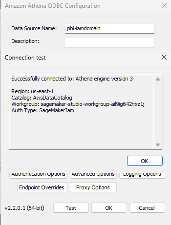
copy customer from 's3://redshift-downloads/TPC-H/2.18/100GB/customer/' iam_role default delimiter '|' region 'us-east-1'; 

copy orders from 's3://redshift-downloads/TPC-H/2.18/100GB/orders/' iam_role default delimiter '|' region 'us-east-1'; 

copy lineitem from 's3://redshift-downloads/TPC-H/2.18/100GB/lineitem/' iam_role default delimiter '|' region 'us-east-1'; 

Run the following query to validate load status. The status column should show as completed. You can also review the information in other columns to see details about the loads such as record counts, duration, and data source.

select * from  SYS_LOAD_HISTORY  Where table_name in ('customer','orders','lineitem');

Output of SYS_LOAD_HISTORY showing successful completion of COPY Jobs
Figure 3: Output of SYS_LOAD_HISTORY showing successful completion of COPY Jobs

  1. Create a materialized view to improve query performance:

Run the following SQL to create a materialized view that pre-compute results set for customer revenues and order volumes by market segment.

CREATE MATERIALIZED VIEW mv_customer_revenue AS 
SELECT 
c.c_custkey, 
c.c_name, 
c.c_mktsegment, 
SUM(l.l_extendedprice * (1 - l.l_discount)) as total_revenue, 
COUNT(DISTINCT o.o_orderkey) as order_count 
FROM customer c 
JOIN orders o ON c.c_custkey = o.o_custkey
JOIN lineitem l ON o.o_orderkey = l.l_orderkey
GROUP BY c.c_custkey, c.c_name, c.c_mktsegment;

Run the following SQL to review the data in the materialized view.

select * from mv_customer_revenue limit 10;

Configure integration with Amazon Quick

Amazon Quick auto discovers the Amazon Redshift provisioned clusters that are associated with your AWS account. These resources must be in the same AWS Region as your Amazon Quick account. For Amazon Redshift clusters in other accounts or Amazon Redshift Serverless, we recommend that you add a VPC connection following the steps in Enabling access to an Amazon Redshift cluster in a VPC documentation. Usually, these steps are performed by your organization’s cloud security administration team.

For serverless, you will apply the same steps in the workgroup instead of the cluster. You can find the VPC and Security Group settings in the Data Access tab of a workgroup.

Amazon Redshift Serverless workgroup VPC and Security groups
Figure 4: Amazon Redshift Serverless workgroup VPC and Security groups

You can also refer to How do I privately connect Quick to an Amazon Redshift or RDS data source in a private subnet? for a demonstration.

Create data source

To create a dataset connecting to Amazon Redshift, complete the following steps.

  1. In the Quick left navigation pane, go to Datasets.
  2. Choose the Data sources tab and select Create data source.
  3. Select Amazon Redshift and enter the following:
    • Data Source Name: Provide customer-rev-datasource as data source name.
    • Connection type: Select the VPC connection created in the previous step.
    • Database server: Enter the Amazon Redshift workgroup endpoint (for example, quick-demo-wg.123456789.us-west-2.redshift-serverless.amazonaws.com).
    • Port: 5439 (default).
    • Database: dev.
    • Username/Password: Amazon Redshift credentials with access to the database.
  4. Choose Validate connection. The validation should be successful.

Amazon Redshift data source configuration
Figure 5: Amazon Redshift data source configuration

  1. Choose Create Data Source to create a data source.

Now let’s explore how to perform all these four steps to configure Athena in Amazon Quick.

Configure and create datasets in Amazon Athena

Amazon Athena provides immediate query capabilities against petabytes of data with automatic scaling to handle concurrent users. Let’s go through the steps to configure connections between Amazon Quick and Amazon Athena.

Set up SQL analytics engine

To create an Athena workgroup:

  1. Open the Amazon Athena console.
  2. In the navigation pane, choose Workgroups.
  3. Choose Create workgroup.
  4. For Workgroup name, enter quick-demo.
  5. For Query result configuration, select Athena managed.
  6. Choose Create workgroup.

Your workgroup is ready immediately for querying data.

Load data and create business views

For Athena, you create tables using the TPC-H benchmark dataset that AWS provides in a public S3 bucket. This approach gives you 1.5 million customer records already optimized in Parquet format without requiring data loading.

To create tables and views in Athena:

  1. Open the Athena Query Editor from the console.
  2. Create a database for your analytics (create S3 bucket if it exists already):
    CREATE DATABASE IF NOT EXISTS athena_demo_db 
    COMMENT 'Analytics database for customer insights' 
    LOCATION 's3://my-analytics-data-lake-[account-id]/';

  3. Create an external table pointing to the TPC-H public dataset:
    CREATE EXTERNAL TABLE IF NOT EXISTS athena_demo_db.customer_csv ( 
      C_CUSTKEY INT, 
      C_NAME STRING, 
      C_ADDRESS STRING, 
      C_NATIONKEY INT, 
      C_PHONE STRING, 
      C_ACCTBAL DOUBLE, 
      C_MKTSEGMENT STRING, 
      C_COMMENT STRING 
    ) 
    
    ROW FORMAT DELIMITED 
    FIELDS TERMINATED BY '|' 
    STORED AS TEXTFILE 
    LOCATION 's3://redshift-downloads/TPC-H/2.18/100GB/customer/' 

  4. Create a business-friendly view for analytics:

Run the following SQL to create a view that aggregates customer account balances grouped by market segments.

CREATE VIEW athena_demo_db.customer_deep_analysis AS 
SELECT 
    c_custkey AS customer_id, 
    c_name AS customer_name, 
    c_mktsegment AS market_segment, 
    c_nationkey, 
    ROUND(c_acctbal, 2) AS account_balance, 
    CASE 
        WHEN c_acctbal < 0    THEN 'At-Risk' 
        WHEN c_acctbal < 2500 THEN 'Low' 
        WHEN c_acctbal < 5000 THEN 'Mid' 
        WHEN c_acctbal < 8000 THEN 'High' 
        ELSE 'Premium' 
    END                                                              
AS balance_tier, 

    ROUND(AVG(c_acctbal) OVER (PARTITION BY c_mktsegment), 2)        AS segment_avg, 
    ROUND(c_acctbal - AVG(c_acctbal) OVER (PARTITION BY c_mktsegment), 2) AS vs_segment_avg, 
    ROUND((c_acctbal - AVG(c_acctbal) OVER (PARTITION BY c_mktsegment)) 
          / NULLIF(STDDEV(c_acctbal) OVER (PARTITION BY c_mktsegment), 0), 2) AS segment_z_score, 
    RANK() OVER (PARTITION BY c_mktsegment ORDER BY c_acctbal DESC)  AS rank_in_segment, 
    NTILE(5) OVER (ORDER BY c_acctbal DESC)                          AS global_quintile 

FROM athena_demo_db.customer_csv 
ORDER BY c_acctbal DESC; 
  1. Verify your view from Athena with:
SELECT * FROM athena_demo_db.customer_deep_analysis limit 5;

Output from the SELECT query
Figure 6: Output from the SELECT query

Configure integration with Amazon Quick

To connect to Amazon Athena in Amazon Quick, follow these steps, consolidated from official AWS documentation and authorizing connections to Amazon Athena.
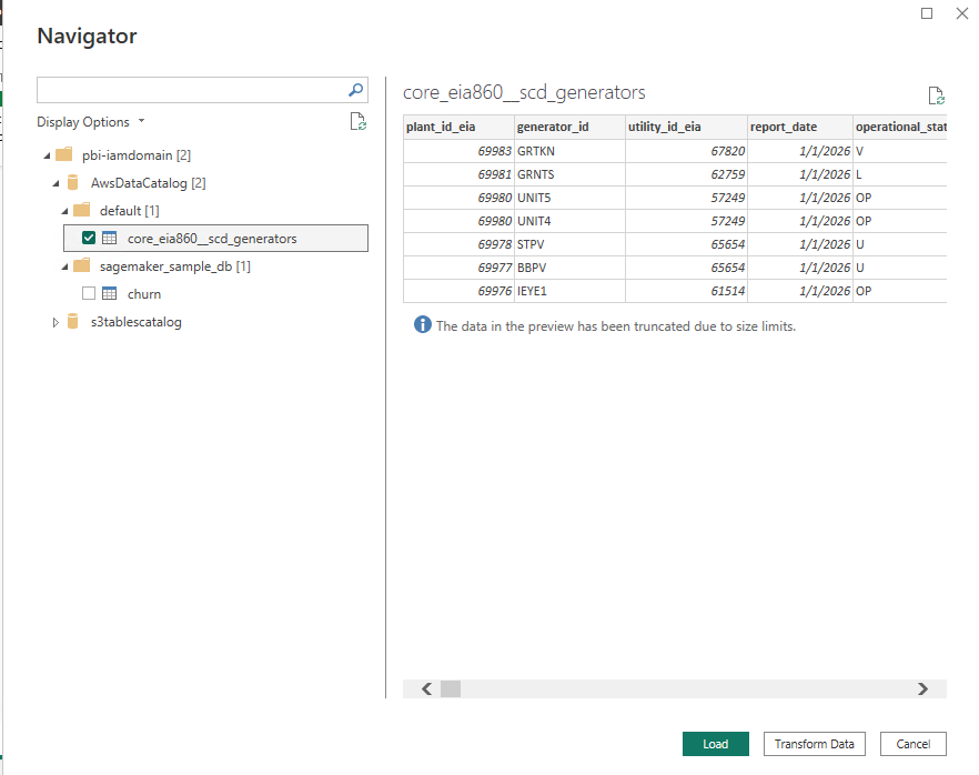
Authorize Quick to Access Athena, S3 Bucket for data, and S3 bucket for Athena Results.

Open the Amazon Quick Security Settings

  • Sign in to the Amazon Quick console as an administrator.
  • In the top-right corner, choose your profile icon, then select Manage account.
  • Under Permissions, choose AWS resources.AWS resource permissions
    Figure 7: AWS resource permissions

Enable Athena Access

  • Under Quick access to AWS services, choose Manage.
  • Locate Amazon Athena in the list of AWS services.
  • If Athena is already selected but access issues persist, clear the checkbox and re-select it to re-enable Athena.
  • Under Amazon S3, select S3 buckets.
  • Check the boxes next to each S3 bucket that Amazon Quick needs to access—including buckets used for Athena query results and any Redshift COPY source buckets.
  • Enable Write permission for Athena Workgroup to allow Amazon Quick to write Athena query results to S3 and choose Finish.
  • Choose Save to update the configuration.

The final step is to grant your Amazon Quick author permissions to query your database, Athena tables, and views. Configuration depends on whether AWS Lake Formation is enabled.

If AWS Lake Formation is not enabled

Permissions are managed at the Quick service role level through standard IAM-based S3 access control. Ensure that the Quick service role (for example, aws-quick-service-role-v0) has the appropriate IAM permissions for the relevant S3 buckets and Athena resources. No additional Lake Formation configuration is required.

If AWS Lake Formation is enabled

Lake Formation acts as the central authorization layer, overriding standard IAM-based S3 permissions. Grant permissions directly to the Amazon Quick author or IAM role.

To grant data permissions:

  1. Open the AWS Lake Formation console.
  2. Choose Permissions, then Data permissions, then Grant.
  3. Select the IAM user or role.
  4. Choose the required databases, tables, and columns.
  5. Grant SELECT at minimum; add DESCRIBE for dataset creation.
  6. Repeat for each user or role that requires access.

Create data source

Follow these steps to create an Athena data source on Amazon Quick.

  1. In the Amazon Quick console, navigate to Datasets and choose Data sources tab.
  2. Choose Create data source, then select the Amazon Athena card.
  3. Enter a Data source name (you can give any name of your choice), select your Athena workgroup (like quick-demo), and choose Validate connection.

Athena data source creation
Figure 8: Athena data source creation

  1. Choose Create data source.

Your Athena data source is now available for building datasets, dashboards, and Topics.

Use Amazon Quick generative AI features

The next steps, from 5–8, demonstrate Amazon Quick generative AI capabilities using Amazon Redshift as a data source. While we use Amazon Redshift in this example, you can substitute with Amazon Athena based on your specific requirements.

Create dashboards

Let’s start by creating datasets from the Amazon Redshift data source.

  1. In the left navigation pane, choose Datasets.
  2. On the Datasets page, choose Create Dataset.
  3. For the data source, select Amazon Redshift data source customer-rev-datasource.
  4. From the menu, choose mv_customer_revenue.

Select table to visualize
Figure 9: Select table to visualize

  1. You can choose one of the following query modes. For this post, select Directly query your data option and choose Visualize.
    • Import to SPICE for quicker analytics – Quick loads a snapshot into its in-memory engine for faster dashboard performance.
    • Directly query your data– Quick runs queries on demand against your query engine.
  2. Select Build icon to open a chat window. Enter “Show me orders by market segments” as the prompt. Note that you need Author Pro access to use this feature.

Build visualization using generative BI feature
Figure 10: Build visualization using generative BI feature

  1. You can change the visual type to a pie chart and add it to the analysis.

Change visual type
Figure 10: Change visual type

To publish your analysis as a dashboard

  1. After you add the visuals, choose Publish.
  2. Enter a name for the dashboard. For this post, use the Market Segment Dashboard.
  3. Choose Publish dashboard. Your dashboard is now available for viewing and sharing.

Create topics and spaces

To fully maximize enterprise data with AI, we must provide the right structure and context. That’s where Topics and Spaces come in. Topics act as natural language interfaces to your structured datasets, automatically analyzing your data, mapping fields, and adding synonyms. Business users can ask “What are total revenues by market segment?” and receive instant, visualized answers without writing a single line of SQL. Spaces bring together all of your related assets into a single collaborative workspace that democratizes data access, reduces context-switching, accelerates team onboarding, so everyone is working from the same trusted, AI-ready data sources.

To create a Quick topic

  1. From the Amazon Quick homepage, choose Topics, then choose Create topic.
  2. Enter a name for your topic. For this post, use Customer Revenue Analytics.
  3. Enter a description. For example:

The Customer Revenue Analytics topic is designed for business users (including analysts, sales operations teams, finance, and market segment owners who need to explore customer and revenue data without SQL expertise. It serves as a natural language interface over the mv_customer_revenue Amazon Redshift dataset, allowing users to ask plain-English questions like “What are total revenues by market segment?” and receive instant, visualized answers. By automatically mapping business language to the underlying schema, it democratizes access to revenue insights across the organization.

  1. Under Dataset, select mv_customer_revenue.
  2. Choose Create. The topic can take 15–30 minutes to enable depending on the data. During this time, Amazon Quick automatically analyzes your data, selects relevant fields, and adds synonyms.
  3. After the topic is enabled, take a few minutes to review and enrich it. The following are some example enrichments.
    1. Add column descriptions to clarify field meaning for business users.
    2. Define preferred aggregations (for example, sum compared to average for revenue fields).
    3. Confirm which fields are Dimensions and which are Measures.
  4. (Optional) To further refine how your topic interprets and responds to queries, add multiple datasets (for example, a customer CSV combined with a database view), custom instructions, filters, and calculated fields.

After your topic is created, its columns are available to add to a Space or to an Agent by selecting it as a data source.


Figure 11: Create a Quick Topic

Create a Space for your team

Spaces bring together dashboards, topics, datasets, documents, and other resources into organized, collaborative workspaces. By centralizing related assets in a single workspace, Spaces reduce context-switching, accelerate onboarding, so everyone is working from the same trusted data sources.

What to include in your Quick Space

  • Dashboard – Add the dashboard Market Segment Dashboard published from your mv_customer_revenue analysis. This gives team members instant access to visualizations such as revenue by market segment, top customers by order volume, and revenue distribution.
  • Topic – Connect the Customer Revenue Analytics (built on the mv_customer_revenue materialized view) to enable natural language queries directly against your Amazon Redshift data.
  • Optionally, you can upload supporting context to ground your team’s analysis:
    • Data dictionary or field definitions for mv_customer_revenue
    • Market segment definitions (AUTOMOBILE, BUILDING, FURNITURE, MACHINERY, HOUSEHOLD)
    • Business rules for revenue calculation (for example, how discounts are applied in the TPC-H model)
    • This implementation guide, so new team members can onboard quickly

To create the Quick Space

  1. From the left navigation menu, choose Spaces, then choose Create space.
  2. Enter a name, for example, Customer Revenue & Segmentation.
  3. Enter a description. For example:

Centralized workspace for customer revenue analysis powered by Amazon Redshift includes interactive dashboards, natural language query access to customer and segment data, and supports documentation for the TPC-H revenue model.
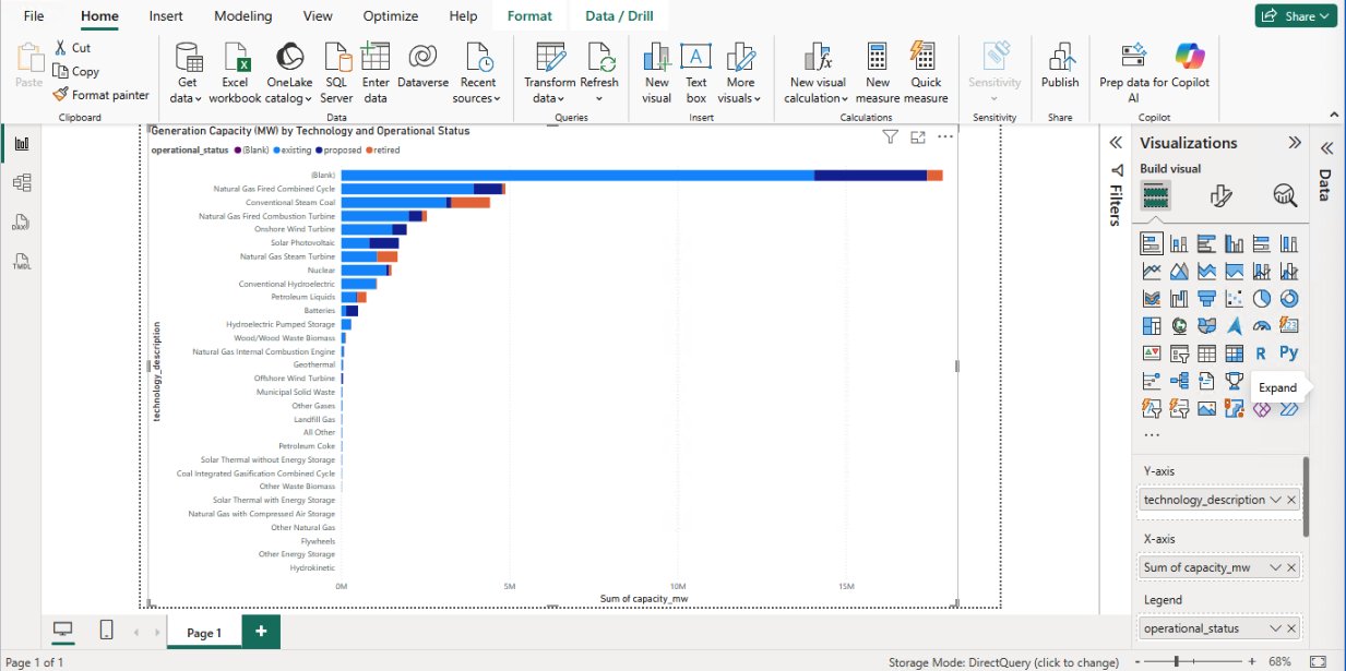
  1. Add knowledge by connecting the Market Segment Dashboard and topic Customer Revenue Analytics.
  2. You can invite team members, such as finance, sales operations, and segment owners, and set appropriate permissions.

Your Space is now ready for collaborative data exploration.


Figure 12: Create a Quick Space

Build chat agents

A custom chat agent delivers conversational AI experiences that understand business context and provide intelligent, grounded responses to user queries. These agents go beyond question-and-answer interactions. They synthesize knowledge from your dashboards, topics, datasets, and documents to explain trends, surface anomalies, guide users through complex analytics workflows, and recommend next steps.

Rather than requiring users to navigate multiple tools or write SQL queries, agents serve as a single conversational interface to your entire analytics environment. Agents can also connect to Actions, pre-built integrations with enterprise tools such as Slack, Microsoft Teams, Outlook, and SharePoint, enabling them to answer questions and trigger real-world workflows, send notifications, create tasks, and interact with external systems directly from the conversation. Custom agents can be tailored to specific business domains, teams, or use cases so that responses align with organizational terminology, data definitions, and business processes. After created, agents can be shared across teams, enabling consistent, actionable, AI-powered data access at scale. For teams working with the mv_customer_revenue dataset, we recommend creating a dedicated Customer Revenue Analysis Agent. This is a purpose-built conversational assistant grounded in your Amazon Redshift data, dashboards, and the Customer Revenue & Segmentation Space.

Create a Quick chat agent

There are two ways that you can use Amazon Quick to create a Quick agent. You can use the navigation menu or directly from Space. The following steps walk you through creating one from the navigation menu.

To create a Quick chat agent

  1. From the left navigation menu, choose Agents, then choose Create agent.
  2. Enter a name for your agent, for example, Customer Revenue Analyst.
  3. Enter a description. For example:

An AI assistant for analyzing customer revenue, market segment performance, and order trends using our Amazon Redshift or data warehouse.

  1. Under Knowledge Sources, add the Customer Revenue & Segmentation Space as a data source. This gives your agent access to the dashboards, topics, and reference documents you’ve already built.
  2. (Optional) Define custom persona instructions to align the agent’s responses with your business context. For example, specifying preferred terminology, response style, or the types of questions it should prioritize.
  3. Choose Launch chat agent.
  4. Start having a conversation with your data. You are welcome to ask any questions. The following are some examples.
    • Which market segment generated most revenue?
    • Show me order trends


Figure 13: Create a Quick Chat agent

To share your Quick chat agent

After your agent is published, choose Share and invite team members or share it across your organization. Custom agents can be tailored to specific business contexts so that different teams can get AI assistance that speaks their language, without needing to configure anything themselves.

Create Quick Flows

Quick Flows automate repetitive tasks and orchestrate multi-step workflows across your entire analytics environment. This removes manual effort, reducing human error, and ensuring consistent execution of critical business processes. Flows can be triggered on a schedule or launched on demand, giving you flexible control over when and how automation runs.

You can build flows that span the full analytics lifecycle: monitoring data quality and flagging anomalies, generating and distributing scheduled reports to stakeholders, and triggering downstream actions in integrated systems such as Slack, Outlook. Amazon Quick gives you three ways to create a flow, so whether you prefer a no-code conversation or a visual step-by-step builder, there’s an option that fits how you work.

To create a flow from chat

  1. While conversing with My Assistant or a custom agent, describe the workflow that you want to automate in plain English.
  2. Amazon Quick generates the flow and offers to create it directly from your conversation — no configuration screens required.

To create a flow from a natural language description

  1. From the left navigation menu, choose Flows, then choose Create flow.
  2. Enter a plain-English description of your workflow. For example:

” Query revenue data by market segments. Filter by order count and all dates. Search web for comparable relevant market trends. Generate formatted summary reports providing market summary and look ahead per segment. ”

  1. Amazon Quick automatically generates the complete workflow with all the necessary steps.
  2. Optionally, you can add additional steps.
  3. Choose Run Mode to test the Flow.
  4. After your flow is created, share it with team members or publish it to your organization’s flow library, so everyone benefits from the same automation without having to rebuild it independently.


Figure 14: Create a Quick Flow to generate summaries and publish dashboards

For more complex flow, review weekly customer revenue summary flow as an example.

  1. Queries the mv_customer_revenue materialized view in Amazon Redshift for the latest weekly revenue figures by market segment.
  2. Compares results against the prior week to calculate segment-level variance.
  3. Generates a formatted summary report and publishes it to the Customer Revenue & Segmentation Space.
  4. Sends a notification through email or Slack to finance, sales operations, and segment owners with a direct link to the updated dashboard.
  5. Flags any segment where revenue has declined more than a defined threshold, routing an alert to the appropriate owner for follow-up.

This flow transforms what might otherwise be a manual, multi-step reporting process into a fully automated pipeline, so stakeholders receive consistent, timely revenue insights without analyst intervention and saving analysts an estimated 3–5 hours per week. For detailed guidance on creating and managing flows, see Using Amazon Quick Flows. Also review Create workflows for routine tasks demo.

Cleanup

Consider deleting the following resources created while following this post to avoid incurring costs. We encourage you to use the trials at no cost as much as possible to familiarize yourself with the features described.

  1. Delete the Amazon Redshift Serverless workgroup and namespace.
  2. Delete Athena workgroup and S3 Buckets.
  3. Delete the Amazon Quick account used while following this post. If you used an existing account, delete the data sets, dashboards, topics, spaces, agents and flows created.

Conclusion

This integrated approach to business intelligence combines the power of AWS SQL analytics engines with Amazon Quick generative AI capabilities to deliver comprehensive analytics solutions. By following these implementation steps, you establish a foundation for traditional BI reporting, interactive dashboards, natural language data exploration, and intelligent workflow automation. The architecture scales from proof-of-concept implementations to production deployments, transforming how organizations access and act on data insights. For more information about Amazon Quick features and capabilities, see the Amazon Quick documentation. To learn more about Amazon Redshift, visit the Amazon Redshift product page. For Amazon Athena details, see the Amazon Athena product page.


About the authors

“Satesh Sonti”

Satesh is a Principal Analytics Specialist Solutions Architect based in Atlanta, specializing in building enterprise data platforms, data warehousing, and analytics solutions. He has over 20 years of experience in building data assets and leading complex data platform programs for banking and insurance clients across the globe.

“Ramon Lopez”

Ramon Lopez is a Principal Solutions Architect for Amazon Quick. With many years of experience building BI solutions and a background in accounting, he loves working with customers, creating solutions, and making world-class services. When not working, he prefers to be outdoors in the ocean or up on a mountain.

Building a scalable, transactional data lake using dbt, Amazon EMR, and Apache Iceberg

Post Syndicated from Umesh Pathak original https://aws.amazon.com/blogs/big-data/building-a-scalable-transactional-data-lake-using-dbt-amazon-emr-and-apache-iceberg/

Growing data volume, variety, and velocity has made it crucial for businesses to implement architectures that efficiently manage and analyze data, while maintaining data integrity and consistency. In this post, we show you a solution that combines Apache Iceberg, Data Build Tool (dbt), and Amazon EMR to create a scalable, ACID-compliant transactional data lake. You can use this data lake to process transactions and analyze data simultaneously while maintaining data accuracy and real-time insights for better decision-making.

Challenges, business imperatives, and technical advantages

Traditional data lakes have long struggled with fundamental limitations. For example, the lack of ACID compliance, data inconsistencies from concurrent writes, complex schema evolution, and the absence of time travel, rollback, and versioning capabilities. These shortcomings directly conflict with growing business demands for concurrent read/write support, robust data versioning and auditing, schema flexibility, and transactional capability within data lake environments. To address these gaps, modern solutions use ACID transactions at scale, optimized storage formats through Apache Iceberg, version control for data on Amazon Simple Storage Service (Amazon S3), and cost-effective, streamlined maintenance—delivering a reliable, enterprise-grade data lake architecture that meets both operational and analytical needs.

Solution overview

The solution is built around four tightly integrated layers that work together to deliver a scalable, transactional data lake.

Raw data is ingested and stored in Amazon S3, which serves as the foundational storage layer. This layer supports multiple data formats and enables efficient data partitioning through Apache Iceberg’s table format. This ensures that data is organized and accessible from the moment it lands. Then, Amazon EMR takes over as the distributed computing engine, using Apache Spark to process large-scale datasets in parallel, handling the heavy lifting of reading, transforming, and writing data across the lake.

Sitting within the processing layer, dbt drives the transformation logic. It applies SQL-based, version-controlled transformations that convert raw, unstructured data in the S3 raw layer into clean, curated datasets stored back in S3. This maintains ACID compliance and schema consistency throughout.

Finally, the curated data is available for consumption through Amazon Athena, which provides a serverless, one-time querying capability directly on S3. With this, analysts and business users can run interactive SQL queries without managing any infrastructure. Together, these components form a continuous pipeline: data flows from ingestion through distributed processing and structured transformation, ultimately surfacing as reliable, query-ready insights.

Amazon EMR is a cloud-based big data service that streamlines the deployment and management of open source frameworks like Apache Spark, Hive, and Trino. It provides a managed Apache Hadoop environment that organizations can use to process and analyze vast amounts of data efficiently.

Data Build Tool is an open source tool that data teams can use to transform and model data using SQL. It promotes best practices for data modeling, testing, and documentation, streamlining maintenance and collaboration on data pipelines.

Apache Iceberg is an open table format designed for large-scale analytics on data lakes. It supports features like transactions, time travel, and data partitioning, which are essential for building reliable and performant data lakes. By using Iceberg, organizations can maintain data integrity and enable efficient querying and processing of data.

When combined, these three technologies provide a powerful solution for building transactional data lakes. Amazon EMR provides the scalable and managed infrastructure for running big data workloads, dbt enables efficient data modeling and transformation, and Apache Iceberg provides data consistency and reliability within the data lake.

Prerequisites

Before proceeding with the solution walkthrough, make sure that the following are in place:

  • AWS Account – An active AWS account with sufficient permissions to create and manage EMR clusters, S3 buckets, Athena workgroups, and AWS Glue Data Catalog resources
  • IAM Roles – The following IAM roles must exist and have appropriate permissions:
    • EMR_DefaultRole – Service role for Amazon EMR
    • EMR_EC2_DefaultRole – Amazon Elastic Compute Cloud (Amazon EC2) instance profile for EMR nodes
  • AWS Command Line Interface (AWS CLI) – Installed and configured with credentials for your target AWS account and AWS Region (refer to Step 1.1 for setup instructions)
  • Python 3.8+ – Installed on your local machine or workspace for setting up the dbt virtual environment
  • Pip – Python package manager available for installing dbt and its dependencies
  • Git – Installed on the EMR primary node or local environment for version control and dbt package management
  • Amazon Athena – Athena query editor access with a configured S3 output location for query results
  • AWS Glue Data Catalog – Enabled as the metastore for Amazon EMR and Athena (no additional setup required if using the default AWS Glue integration)
  • S3 Bucket Naming – Prepare a unique identifier to suffix S3 bucket names, ensuring global uniqueness across all three buckets created in Step 1.3
  • Network Access – Make sure that your local machine can reach the Amazon EMR primary node’s DNS over port 10001 (Thrift/HiveServer2) for dbt connectivity; configure security groups accordingly

Solution walkthrough

Step 1: Environment setup

  1. Install the AWS CLI on your workspace by following the instructions in Installing or updating the latest version of the AWS CLI. To configure AWS CLI interaction with AWS, refer to Quick setup.
  2. Create EMR cluster.

    Create the following JSON file with the following contents emr-config.json:

    [
      {
        "Classification": "iceberg-defaults",
        "Properties": {
          "iceberg.enabled": "true"
        }
      },
      {
        "Classification": "spark-hive-site",
        "Properties": {
          "hive.metastore.client.factory.class": "com.amazonaws.glue.catalog.metastore.AWSGlueDataCatalogHiveClientFactory"
        }
      }
    ]

    Run the following command on your AWS CLI, updating the preferred AWS Region:

    aws emr create-cluster \
    --name "Iceberg-DBT-Cluster" \
    --release-label emr-7.7.0 \
    --applications Name=Spark Name=Hive Name=Livy \
    --ec2-attributes InstanceProfile=EMR_EC2_DefaultRole \
    --instance-type c3.4xlarge \
    --instance-count 1 \
    --service-role EMR_DefaultRole \
    --configurations file://emr-config.json \
    --region [region]

  3. Set up S3 buckets.
    Create the following S3 bucket using the AWS CLI after updating the bucket name.

    aws s3 mb s3://amzn-s3-demo-transactional-datalake-raw-[unique-identifier]
    aws s3 mb s3://amzn-s3-demo-transactional-datalake-curated-[unique-identifier]
    aws s3 mb s3://amzn-s3-demo-transactional-datalake-analytics-[unique-identifier]
    

Step 2. Raw layer implementation

The raw layer serves as the foundation of our data lake, ingesting and storing data in its original form. This layer is important for maintaining data lineage and enabling reprocessing if needed. We use Apache Iceberg tables to store our raw data, which provides benefits such as ACID transactions, schema evolution, and time travel capabilities.

In this step, we create a dedicated database for our raw data and set up tables for customers, products, and sales using Amazon Athena. These tables are configured to use the Iceberg table format and are compressed using the ZSTD algorithm to optimize storage. The LOCATION property specifies where the data will be stored in Amazon S3 so that data is organized and accessible.

After creating the tables, we insert sample data to simulate real-world scenarios. We use this data throughout the rest of the implementation to demonstrate the capabilities of our data lake architecture.

Update the respective bucket name in each create table bucket name from the previous step:

  1. Create database and tables
    -- Create Raw Database
    CREATE SCHEMA raw_sales_analytics_data_layer;
    
    -- Create Customers Table
    CREATE TABLE raw_sales_analytics_data_layer.customers (
        CustomerID string,
        CustomerName string,
        Region string,
        inserted_timestamp timestamp
    )
    LOCATION 's3://[bucket_name]/raw_sales_analytics_data_layer/customers'
    TBLPROPERTIES (
        'table_type'='iceberg', 
        'write_compression'='zstd'
    );
    
    -- Create Products Table
    CREATE TABLE raw_sales_analytics_data_layer.products (
        productid string,
        productname string,
        category string,
        supplier string,
        inserted_timestamp timestamp
    )
    LOCATION 's3://[bucket_name]/raw_sales_analytics_data_layer/products'
    TBLPROPERTIES (
        'table_type'='iceberg', 
        'write_compression'='zstd'
    );

  2. Insert sample data
    -- Insert Customers
    INSERT INTO raw_sales_analytics_data_layer.customers
    VALUES 
        ('201', Jane Doe', 'Central', current_timestamp),
        ('202', Arnav Desai, 'North', current_timestamp),
        ('203', Kwaku Mensah, 'West', current_timestamp);
    
    -- Insert Products
    INSERT INTO raw_sales_analytics_data_layer.products
    VALUES
        ('1', 'Laptop', 'Electronics', 'AnyAuthority', current_timestamp),
        ('2', 'Smartphone', 'Electronics', 'AnyCompany', current_timestamp);
    
    -- Insert Sales
    INSERT INTO raw_sales_analytics_data_layer.sales
    VALUES
        ('ORD001', '1', '201', '2025-04-01', 1299.99, current_timestamp),
        ('ORD002', '2', '202', '2025-04-02', 899.99, current_timestamp);

Step 3: dbt setup and configuration

Setting up dbt involves installing the necessary packages, configuring the connection to the data warehouse (in this case, Amazon EMR), and setting up the project structure.

We start by creating a Python virtual environment to isolate our dbt installation. Then, we install dbt-core and the Spark adapter, which allows dbt to connect to the EMR cluster. The profiles.yml file is configured to connect to the EMR cluster using the Thrift protocol, while the dbt_project.yml file defines the overall structure of the dbt project, including model materialization strategies and file formats.

  1. Install prerequisites
    # Create Python virtual environment
    python -m venv dbt-env
    source dbt-env/bin/activate
    
    # Install required packages
    pip install dbt-core dbt-spark[PyHive]
    
    # Install git
    yum install git

  2. Configure dbt profiles
    # ~/.dbt/profiles.yml
    sales_analytics:
      target: dev
      outputs:
        dev:
          type: spark
          method: thrift
          host: your-emr-master-dns
          port: 10001
          schema: curated_sales_analytics_data_layer
          threads: 4

  3. Project configuration
    # dbt_project.yml
    name: 'sales_analytics'
    version: '1.0.0'
    config-version: 2
    
    profile: 'sales_analytics'
    
    model-paths: ["models"]
    analysis-paths: ["analyses"]
    test-paths: ["tests"]
    seed-paths: ["seeds"]
    macro-paths: ["macros"]
    
    target-path: "target"
    clean-targets:
        - "target"
        - "dbt_packages"
    
    models:
      sales_analytics:
        dim:
          +materialized: table
          +file_format: iceberg
        ads:
          +materialized: table
          +file_format: iceberg

Step 4: dbt models implementation

In this step, we implement dbt models, which define the transformations that we will apply to raw data. We start by configuring data sources in the sources.yml file, which allows dbt to reference raw tables easily.

We then create dimension models for customers and products, and a fact model for sales.

These models use incremental materialization strategies to efficiently update data over time. The incremental strategy processes only new or updated records, significantly reducing the time and resources required for each run.

  1. Source configuration
    # models/sources.yml
    version: 2
    sources:
      - name: raw_sales
        database: raw_sales_analytics_data_layer
        schema: raw_sales_analytics_data_layer
        tables:
          - name: customers
            columns:
              - name: CustomerID
                tests:
                  - unique
                  - not_null
          - name: products
          - name: sales

  2. Dimension models
    -- models/dim/dim_customers.sql
    {{ config(
        materialized='incremental',
        unique_key='customerid',
        incremental_strategy='merge'
    ) }}
    
    WITH source_data AS (
        SELECT 
            customerid,
            customername,
            region,
            inserted_timestamp,
            ROW_NUMBER() OVER (
                PARTITION BY customerid 
                ORDER BY inserted_timestamp DESC
            ) as row_number
        FROM {{ source('raw_sales_analytics_data_layer', 'customers') }}
        {% if is_incremental() %}
        WHERE inserted_timestamp > (SELECT MAX(inserted_timestamp) FROM {{ this }})
        {% endif %}
    )
    
    SELECT 
        customerid,
        customername,
        region,
        inserted_timestamp
    FROM source_data
    WHERE row_number = 1

  3. Product models
    -- models/dim/dim_products.sql
    {{ config(
        materialized='incremental',
        unique_key='productid',
        incremental_strategy='merge'
    ) }}
    
    WITH source_data AS (
        SELECT
            productid,
            productname,
            category,
            supplier,
            inserted_timestamp,
            ROW_NUMBER() OVER (
                PARTITION BY productid
                ORDER BY inserted_timestamp DESC
            ) as row_number
        FROM {{ source('raw_sales_analytics_data_layer', 'products') }}
        {% if is_incremental() %}
        WHERE inserted_timestamp > (SELECT MAX(inserted_timestamp) FROM {{ this }})
        {% endif %}
    )
    
    SELECT
        s.productid,
        s.productname,
        s.category,
        s.supplier,
        s.inserted_timestamp
    FROM source_data s
    WHERE s.row_number = 1
    {% if is_incremental() %}
        AND NOT EXISTS (
            SELECT 1
            FROM {{ this }} t
            WHERE t.productid = s.productid
            AND t.inserted_timestamp >= s.inserted_timestamp
        )
    {% endif %}

  4. Fact models
    -- models/dim/fact_sales.sql
    {{ config(
        materialized='incremental',
        unique_key='orderid',
        incremental_strategy='merge'
    ) }}
    
    WITH source_data AS (
        SELECT
            orderid,
            productid,
            customerid,
            date,
            salesamount,
            inserted_timestamp,
            ROW_NUMBER() OVER (
                PARTITION BY orderid
                ORDER BY inserted_timestamp DESC
            ) as row_number
        FROM {{ source('raw_sales_analytics_data_layer', 'sales') }}
        {% if is_incremental() %}
        WHERE orderid NOT IN (SELECT orderid FROM {{ this }})  -- Changed condition
        {% endif %}
    )
    
    SELECT
        s.orderid,
        s.productid,
        s.customerid,
        s.date,
        s.salesamount,
        s.inserted_timestamp
    FROM source_data s
    WHERE s.row_number = 1

Step 5: Analytics layer

The analytics layer builds upon dimension and fact models to create more complex analyzes. In this step, we create a daily sales analysis model that combines data from fact_sales, dim_customers, and dim_products models.

We also implement a customer insights model that analyzes purchase patterns across different Regions and product categories.

These analytics models demonstrate how we can use our transformed data to generate valuable business insights. By materializing these models as Iceberg tables, we make sure that they benefit from the same ACID transactions and time travel capabilities as our raw and transformed data.

  1. Daily sales analysis

    The analytics layer introduces a fact_sales_analysis model that consolidates transactional sales data with customer and product dimensions to enable business-ready reporting. Built as an incremental model with a merge strategy, it efficiently processes data by deduplicating records using the latest inserted timestamp per order, enabling reliable downstream consumption without full table refreshes.

    -- models/ads/fact_sales_analysis.sql
    {{ config(
        materialized='incremental',
        unique_key='orderid',
        incremental_strategy='merge'
    ) }}
    
    WITH source_data AS (
        SELECT
            s.orderid,
            s.date,
            s.salesamount,
            c.customername,
            c.region,
            p.productname,
            p.category,
            p.supplier,
            s.inserted_timestamp,
            ROW_NUMBER() OVER (
                PARTITION BY s.orderid
                ORDER BY s.inserted_timestamp DESC
            ) as row_number
        FROM {{ ref('fact_sales') }} s
        JOIN {{ ref('dim_customers') }} c ON s.customerid = c.customerid
        JOIN {{ ref('dim_products') }} p ON s.productid = p.productid
        {% if is_incremental() %}
        WHERE s.orderid NOT IN (SELECT orderid FROM {{ this }})
        {% endif %}
    )
    
    SELECT
        s.orderid,
            s.date,
            s.salesamount,
            s.customername,
            s.region,
            s.productname,
            s.category,
            s.supplier,
            s.inserted_timestamp
    FROM source_data s
    WHERE s.row_number = 1

  2. Customer insights

    The customer_purchase_patterns model aggregates sales activity across customer Regions and product categories to surface revenue trends and buying behavior. Materialized as an Iceberg table in the analytics schema, it provides a performant and scalable foundation for customer segmentation, Regional performance analysis, and category-level revenue attribution.

    -- models/analytics/customer_purchase_patterns.sql
    {{
        config(
            materialized='table',
            file_format='iceberg',
            schema='analytics'
        )
    }}
    
    SELECT
        dc.Region,
        dp.category,
        COUNT(DISTINCT fs.orderid) as total_orders,
        COUNT(DISTINCT dc.customerid) as unique_customers,
        SUM(fs.salesamount) as total_revenue,
        SUM(fs.salesamount) / COUNT(DISTINCT dc.customerid) as revenue_per_customer
    FROM {{ ref('fact_sales') }} fs
    JOIN {{ ref('dim_customers') }} dc ON fs.customerid = dc.customerid
    JOIN {{ ref('dim_products') }} dp ON fs.productid = dp.productid
    GROUP BY dc.Region, dp.category

Step 6: Transactional operations and time travel with Apache Iceberg

This section demonstrates how to use Apache Iceberg’s time travel capabilities and transactional operations using actual snapshot data from our dim_customers table. We walk through querying data at different points in time and comparing changes between snapshots.

  1. Transactional capabilities

    Let’s first look at current data:

    Now, modify the raw layer data for customerid 201 and change the Region to East

    Run the dbt model for dim_customers to sync the changes

    Validate the data in curated layer for dim_customers dimension table

  2. Time-travel capabilities

    First, let’s fetch snapshots for customers dimension table in curated layer

    Now, find the data state before and after the modification.

Step 7: Data quality tests

Data quality is a critical pillar of any reliable data pipeline. In this step, we define and enforce quality checks directly within the dbt project using schema-level test configurations. Rather than relying on one-time validation scripts, with dbt’s built-in testing framework, we can declaratively specify expectations on our models, ensuring that key fields remain unique, non-null, and consistent across the data layer before they reach downstream consumers.

  1. Generic tests configuration

    The schema.yml file serves as the central contract for model integrity. Here, we apply generic tests on the fact_sales and dim_customers models to catch data anomalies early in the pipeline.

    # models/schema.yml
    version: 2
    
    models:
      - name: fact_sales
        columns:
          - name: orderid
            tests:
              - unique
              - not_null
          - name: salesamount
            tests:
              - not_null
    
      - name: dim_customers
        columns:
          - name: customerid
            tests:
              - unique
              - not_null

Step 8: Maintenance procedures

A well-functioning data pipeline requires ongoing maintenance to remain performant and auditable over time. This step covers two essential practices, table optimization to keep data storage efficient, and snapshot management to track historical changes in source data. Together, these procedures keep the pipeline reliable, cost-effective, and capable of supporting time-based analysis.

  1. Table optimization

    As data accumulates in Delta or Iceberg tables, small files and fragmented storage can degrade query performance. The optimize_table macro provides a reusable utility to run Databricks’ OPTIMIZE command on any target table, consolidating small files and improving read efficiency without manual intervention.

    -- macros/optimize_table.sql
    {% macro optimize_table(table_name) %}
        {% set query %}
            OPTIMIZE {{ table_name }}
        {% endset %}
        {% do run_query(query) %}
    {% endmacro %}

  2. Snapshot management

    To maintain a historical record of customer data changes, we use dbt snapshots with a timestamp-based strategy. The customers_snapshot model captures row-level changes from the raw source layer and persists them in a dedicated snapshots schema, enabling point-in-time analysis and audit trails.

    -- snapshots/customer_snapshot.sql
    {% snapshot customers_snapshot %}
    {{
        config(
          target_schema='snapshots',
          unique_key='CustomerID',
          strategy='timestamp',
          updated_at='inserted_timestamp'
        )
    }}
    
    SELECT * FROM {{ source('raw_sales_analytics_data_layer', 'customers') }}
    
    {% endsnapshot %}

Step 9: Monitoring and logging

Observability is an essential aspect of any production-grade data pipeline. This step establishes logging and monitoring practices within the dbt project to track pipeline runs, capture errors, and support debugging. With structured logging enabled, teams gain visibility into model execution, test results, and runtime behavior, streamlining issue diagnosis and maintaining operational confidence.

  1. dbt logging configuration

    The dbt_project.yml logging configuration directs dbt to write logs to a dedicated path and outputs them in JSON format. JSON-structured logs are particularly useful for integration with log aggregation tools and monitoring dashboards, enabling automated alerting and audit trail management.

    # dbt_project.yml
    logs:
      path: logs
      enable_json: true

Step 10. Deployment and running

With the pipeline fully built, tested, and maintained, the final step covers how to deploy and execute dbt models across different scenarios. Whether running a complete refresh, processing incremental updates, or validating data quality, these commands form the operational backbone of day-to-day pipeline management.

  1. Full refresh

    A full refresh rebuilds all models from scratch, reprocessing the entire dataset. This is typically used after significant schema changes, backfills, or when incremental state needs to be reset.

    dbt run --full-refresh

  2. Incremental update

    For routine pipeline runs, incremental updates process only new or changed data, significantly reducing compute time and cost. The following command targets specific models (dim_customers and fact_sales) allowing selective execution without triggering the full DAG.

    dbt run --select dim_customers fact_sales

  3. Testing

    After models are run, data quality tests defined in the schema configuration are executed to validate integrity across all models. This validates that constraints such as uniqueness and non-null checks are met before data reaches downstream consumers.

    dbt test

Step 11. Cleanup

  1. Infrastructure cleanup
    # Delete EMR cluster
    aws emr terminate-clusters --cluster-id <cluster-id>
    
    # Remove S3 buckets
    aws s3 rb s3://amzn-s3-demo-transactional-datalake-raw-bucket-[unique-identifier] --force
    aws s3 rb s3://amzn-s3-demo-transactional-datalake-curated-bucket-[unique-identifier] --force
    aws s3 rb s3://amzn-s3-demo-transactional-datalake-analytics-bucket-[unique-identifier] --force

  2. Database cleanup
    DROP SCHEMA raw_sales_analytics_data_layer CASCADE;
    DROP SCHEMA curated_sales_analytics_data_layer CASCADE;

Conclusion

In this post, you learned how to build a transactional data lake on Amazon EMR using dbt and Apache Iceberg, from environment setup and modeling raw data, to quality enforcing, snapshot management, and incremental pipeline deployment. The architecture brings together the scalability of Amazon EMR, dbt’s transformation capabilities, and Iceberg’s ACID-compliant table format to deliver a reliable, maintainable, and cost-efficient data platform.

To get started, see the Amazon EMR documentation to deploy this architecture in your own environment. Whether you’re modernizing a legacy data platform or building a new analytics foundation, this stack gives you the flexibility to scale with confidence.
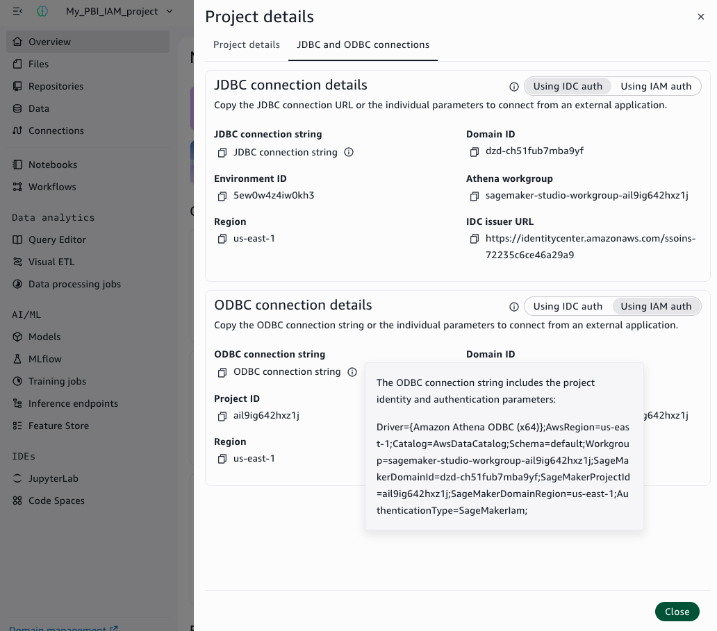

About the authors

Umesh Pathak

Umesh Pathak

Umesh is a Data Analytics Lead Consultant at AWS ProServe, based in India. When not solving complex data challenges, Umesh is out on the trails — an avid runner and hiker who brings the same discipline and drive to fitness as he does to his work.

Amol Guldagad

Amol Guldagad

Amol is a Data Analytics Lead Consultant based in India. He helps customers to accelerate their journey to the cloud and innovate using AWS analytics services.

Amazon Athena adds 1-minute reservations and new capacity control features

Post Syndicated from Manan Nayar original https://aws.amazon.com/blogs/big-data/amazon-athena-adds-1-minute-reservations-and-new-capacity-control-features/

Many of you choose serverless services for your analytics workloads because of its simplicity and elasticity. But many of you running mission-critical queries face a common challenge: ensuring your high-priority workloads run when needed and without interference from other queries in your account.

Amazon Athena is a serverless interactive query service that makes it simple to analyze data using SQL. Capacity Reservations is a feature of Athena that addresses the need to run critical workloads by providing dedicated serverless capacity for the workloads you specify. With Capacity Reservations, you request capacity in the form of Data Processing Units (DPU) and you assign them to your workloads.

In this post, we highlight three new capabilities that make Capacity Reservations more flexible and easier to manage: reduced minimums for fine-grained capacity adjustments, an autoscaling solution for dynamic workloads, and capacity cost and performance controls.

Now available: 1-minute reservations and 4 DPU minimum

Yesterday, we announced a big change for Capacity Reservations: you can now reserve as few as 4 DPU (down from 24 DPU) for as little as 1 minute (down from 60 minutes). This update lets you make frequent, fine-grained capacity adjustments to closely match your workload patterns and hold less capacity, with savings up to 95% for workloads that complete in under an hour.

We’ve optimized Athena for interactive queries that need a quick response, but many of you use Athena for non-interactive queries as well. For example, you may have queries that run on a schedule to prepare data for downstream analysis or perform updates to Apache Iceberg tables. These queries often process larger volumes of data and run for longer than interactive queries. If you’re using Athena’s scan-based pricing option, all your queries count towards your account-level quota. This means that your latency sensitive interactive queries can sometimes end up queued behind non-interactive queries that are running in your account.

Capacity Reservations addresses prioritization problems like this by making it possible to assign dedicated capacity to Athena workgroups. For example, Twilio operates a query platform that serves 1,500+ users who run over 2.5 million queries per month. They use Capacity Reservations for important workloads that need to have dedicated capacity to run optimally and avoid competing with other workloads.

Capacity Reservations have worked well when your workloads have been large and predictable. For example, users accessing dashboards at the start of the workday, or data processing jobs that run continuously 24/7. However, you’ve told us that you wanted more flexibility to update your reservations more frequently, to better match changes in demand.

With Athena’s new 4 DPU and 1-minute minimums, you’re now able to adjust capacity more frequently and match demand more closely than before. We’re excited to see how these updates benefit your mission-critical query workloads.

Autoscaling for dynamic workloads

The reduced minimums enable frequent capacity adjustments, but making those adjustments requires effort. Consider a business intelligence workload that peaks in the morning as executives review dashboards but decreases throughout the day. You want this workload isolated so that high-priority queries aren’t queued behind less important queries.

With 1-minute minimums, you can now adjust capacity to closely track these patterns. However, manually adjusting capacity this frequently is tedious—you need to monitor utilization, decide when to scale, and periodically adjust DPU.

We recently launched an autoscaling solution that uses AWS Step Functions to orchestrate capacity adjustments. It monitors capacity utilization metrics that Athena emits to Amazon CloudWatch at 1-minute granularity, analyzes utilization signal over configurable intervals, then conditionally adds or removes DPU so you can maintain consistent performance even during traffic spikes.

We have made this available as a 1-click deployment from the Athena console: just click Set up autoscaling on the details page for your reservation. When you do, a AWS CloudFormation template sets up all the resources you need. Among the resources set up is the Step Functions state machine, which you can view by opening Athena’s left-side navigation menu and clicking Workflows.

You can also find the template and information on the configurable autoscaling parameters in our documentation. See Automatically adjust capacity in the Athena User Guide.

We chose Step Functions for this solution to enable extensibility and customization. Step Functions integrates tightly with AWS services and allows you to define sophisticated state machines in Amazon States Language, a JSON-based language for serverless workflows. This makes it straightforward to add conditional logic, integrate additional services, or modify the workflow to match your specific requirements.

Control DPU usage at the workgroup and query levels

Part of the ease of use and simplicity of Athena is that it allocates capacity to queries automatically based on their complexity. However, sometimes preventing a single query from using too much capacity or operating at a required level of concurrency is more important than individual query performance. We recently released new DPU cost and performance controls so you can set constraints on Athena’s capacity allocation behavior when you’re using Capacity Reservations.

You can control DPU allocation in two places: workgroup-level controls that apply to all queries in that workgroup, or per query using the StartQueryExecution API. Both approaches set a type of budget that Athena adheres to when planning queries and determining how much capacity to allocate.

You can set minimum and maximum DPU limits from 4 to 124 DPU in increments of 4. Setting a maximum prevents Athena from allocating more DPU than specified. When you set a minimum, you instruct Athena to allocate at least the specified DPU. This can be beneficial when you know that a specific query requires a specific number of DPU to run optimally for your use case. Set both to create a range. For example, a minimum of 4 and maximum of 16 lets Athena start with 4 DPU and scale to 16 if needed. Setting them to the same value forces queries to run on an exact number of DPU.

Controls that you set at the workgroup-level are visible in the workgroup details page and the reservation that the workgroup has been added to.

Last but not least: every query you run on reserved capacity now reports its DPU usage in the Athena console and GetQueryExecution / BatchGetQueryExecution APIs, giving you complete visibility into capacity utilization.

Moving to Capacity Reservations

Getting started with Capacity Reservations involves creating a reservation with your desired DPU count, then assigning workgroups to that reservation. For end users, nothing changes. You continue running queries as usual and no SQL changes are needed. For administrators, you create a Capacity Reservation with your desired DPU count, then assign workgroups to that reservation. Athena automatically routes queries from assigned workgroups to your reserved capacity, isolated from other queries in your account and no impact to your account-level concurrency quota.

Conclusion

These updates to Capacity Reservations give you greater flexibility and control over your Athena workloads. The reduced minimums let you adjust capacity in smaller increments and shorter time windows, allowing you to match your usage patterns more closely than before. Autoscaling eliminates the work of making those adjustments manually. And DPU controls give you fine-grained influence over how individual queries consume capacity. Together, these capabilities help you optimize costs, manage concurrency, and deliver predictable performance for your most critical workloads—all while preserving Athena’s serverless benefits.

To learn more, see Athena Capacity Reservations in the Athena User Guide, Athena pricing page, or create your first Capacity Reservation in the Athena console.


About the authors

Manan Nayar

Manan Nayar

Manan is a Software Engineer at AWS based in Vancouver with over 8 years of experience building high-scale distributed systems and data platforms. In his spare time, he’s an avid runner and hiker who enjoys exploring the outdoors and staying active.

Mario Alkhoury

Mario Alkhoury

Mario is a Software Engineer on the Athena team, where he works on distributed systems, Capacity Reservations, and drivers. Based in the San Francisco Bay Area, he enjoys reading and spending time with family and friends outside of work.

Saroj Yadav

Saroj Yadav

Saroj is a Software Development Manager with AWS, driving innovations in data analytics with Amazon Athena and previously AWS Glue. Over the last 25 years, she has scaled infrastructure and delivered software products for companies during periods of hypergrowth.

Pathik Shah

Pathik Shah

Pathik is a Sr. Analytics Architect at Amazon Web Services. He joined AWS in 2015 and has been focusing on the big data analytics space since then, helping customers build scalable and robust solutions using AWS analytics services.

Theo Tolv

Theo Tolv

Theo is a Principal Analytics Architect based in Stockholm, Sweden. He’s worked with small and big data for most of his career and has built applications running on AWS since 2008. In his spare time, he likes to tinker with electronics and read space opera.

Scott Rigney

Scott Rigney

Scott is a Principal Technical Product Manager with the Amazon Athena service and works out of Arlington, Virginia. Scott has worked in the data, analytics, and machine learning space for longer than he’d like to admit.

Using Amazon EMR DeltaStreamer to stream data to multiple Apache Hudi tables

Post Syndicated from Gautam Bhaghavatula original https://aws.amazon.com/blogs/big-data/using-amazon-emr-deltastreamer-to-stream-data-to-multiple-apache-hudi-tables/

In this post, we show you how to implement real-time data ingestion from multiple Kafka topics to Apache Hudi tables using Amazon EMR. This solution streamlines data ingestion by processing multiple Amazon Managed Streaming for Apache Kafka (Amazon MSK) topics in parallel while providing data quality and scalability through change data capture (CDC) and Apache Hudi.

Organizations processing real-time data changes across multiple sources often struggle with maintaining data consistency and managing resource costs. Traditional batch processing requires reprocessing entire datasets, leading to high resource usage and delayed analytics. By implementing CDC with Apache Hudi’s MultiTable DeltaStreamer, you can achieve real-time updates; efficient incremental processing with atomicity, consistency, isolation, durability (ACID) guarantees; and seamless schema evolution while minimizing storage and compute costs.

Using Amazon Simple Storage Service (Amazon S3), Amazon CloudWatch, Amazon EMR, Amazon MSK and AWS Glue Data Catalog, you’ll build a production-ready data pipeline that processes changes from multiple data sources simultaneously. Through this tutorial, you’ll learn to configure CDC pipelines, manage table-specific configurations, implement 15-minute sync intervals, and maintain your streaming pipeline. The result is a robust system that maintains data consistency while enabling real-time analytics and efficient resource utilization.

What is CDC?

Imagine a constantly evolving data stream, a river of information where updates flow continuously. CDC acts like a sophisticated net, capturing only the modifications—the inserts, updates, and deletes—happening within that data stream. Through this targeted approach, you can focus on the new and changed data, significantly improving the efficiency of your data pipelines.There are numerous advantages to embracing CDC:

  • Reduced processing time – Why reprocess the entire dataset when you can focus only on the updates? CDC minimizes processing overhead, saving valuable time and resources.
  • Real-time insights – With CDC, your data pipelines become more responsive. You can react to changes almost instantaneously, enabling real-time analytics and decision-making.
  • Simplified data pipelines – Traditional batch processing can lead to complex pipelines. CDC streamlines the process, making data pipelines more manageable and easier to maintain.

Why Apache Hudi?

Hudi simplifies incremental data processing and data pipeline development. This framework efficiently manages business requirements such as data lifecycle and improves data quality. You can use Hudi to manage data at the record-level in Amazon S3 data lakes to simplify CDC and streaming data ingestion and handle data privacy use cases requiring record-level updates and deletes. Datasets managed by Hudi are stored in Amazon S3 using open storage formats, while integrations with Presto, Apache Hive, Apache Spark, and Data Catalog give you near real time access to updated data. Apache Hudi facilitates incremental data processing for Amazon S3 by:

  • Managing record-level changes – Ideal for update and delete use cases
  • Open formats – Integrates with Presto, Hive, Spark, and Data Catalog
  • Schema evolution – Supports dynamic schema changes
  • HoodieMultiTableDeltaStreamer – Simplifies ingestion into multiple tables using centralized configurations

Hudi MultiTable Delta Streamer

The HoodieMultiTableStreamer offers a streamlined approach to data ingestion from multiple sources into Hudi tables. By processing multiple sources simultaneously through a single DeltaStreamer job, it eliminates the need for separate pipelines while reducing operational complexity. The framework provides flexible configuration options, and you can tailor settings for diverse formats and schemas across different data sources.

One of its key strengths lies in unified data delivery, organizing information in respective Hudi tables for seamless access. The system’s intelligent upsert capabilities efficiently handle both inserts and updates, maintaining data consistency across your pipeline. Additionally, its robust schema evolution support enables your data pipeline to adapt to changing business requirements without disruption, making it an ideal solution for dynamic data environments.

Solution overview

In this section, we show how to stream data to Apache Hudi Table using Amazon MSK. For this example scenario, there are data streams from three distinct sources residing in separate Kafka topics. We aim to implement a streaming pipeline that uses the Hudi DeltaStreamer with multitable support to ingest and process this data at 15-minute intervals.

Mechanism

Using MSK Connect, data from multiple sources flows into MSK topics. These topics are then ingested into Hudi tables using the Hudi MultiTable DeltaStreamer. In this sample implementation, we create three Amazon MSK topics and configure the pipeline to process data in JSON format using JsonKafkaSource, with the flexibility to handle Avro format when needed through the appropriate deserializer configuration

The following diagram illustrates how our solution processes data from multiple source databases through Amazon MSK and Apache Hudi to enable analytics in Amazon Athena. Source databases send their data changes—including inserts, updates, and deletes—to dedicated topics in Amazon MSK, where each data source maintains its own Kafka topic for change events. An Amazon EMR cluster runs the Apache Hudi MultiTable DeltaStreamer, which processes these multiple Kafka topics in parallel, transforming the data and writing it to Apache Hudi tables stored in Amazon S3. Data Catalog maintains the metadata for these tables, enabling seamless integration with analytics tools. Finally, Amazon Athena provides SQL query capabilities on the Hudi tables, allowing analysts to run both snapshot and incremental queries on the latest data. This architecture scales horizontally as new data sources are added, with each source getting its dedicated Kafka topic and Hudi table configuration, while maintaining data consistency and ACID guarantees across the entire pipeline.

To set up the solution, you need to complete the following high-level steps:

  1. Set up Amazon MSK and create Kafka topics
  2. Create the Kafka topics
  3. Create table-specific configurations
  4. Launch Amazon EMR cluster
  5. Invoke the Hudi MultiTable DeltaStreamer
  6. Verify and query data

Prerequisites

To perform the solution, you need to have the following prerequisites. For AWS services and permissions, you need:

  • AWS account:
  • IAM roles:
    • Amazon EMR service role (EMR_DefaultRole) with permissions for Amazon S3, AWS Glue and CloudWatch.
    • Amazon EC2 instance profile (EMR_EC2_DefaultRole) with S3 read/write access.
    • Amazon MSK access role with appropriate permissions.
  • S3 buckets:
    • Configuration bucket for storing properties files and schemas.
    • Output bucket for Hudi tables.
    • Logging bucket (optional but recommended).
  • Network configuration:
  • Development tools:

Set up Amazon MSK and create Kafka topics

In this step, you’ll create an MSK cluster and configure the required Kafka topics for your data streams.

  1. To create an MSK cluster:
aws kafka create-cluster \
    --cluster-name hudi-msk-cluster \
    --broker-node-group-info file://broker-nodes.json \
    --kafka-version "2.8.1" \
    --number-of-broker-nodes 3 \
    --encryption-info file://encryption-info.json \
    --client-authentication file://client-authentication.json
  1. Verify the cluster status:

aws kafka describe-cluster --cluster-arn $CLUSTER_ARN | jq '.ClusterInfo.State'

The command should return ACTIVE when the cluster is ready.

Schema setup

To set up the schema, complete the following steps:

  1. Create your schema files.
    1. input_schema.avsc:
      {
          "type": "record",
          "name": "CustomerSales",
          "fields": [
              {"name": "Id", "type": "string"},
              {"name": "ts", "type": "long"},
              {"name": "amount", "type": "double"},
              {"name": "customer_id", "type": "string"},
              {"name": "transaction_date", "type": "string"}
          ]
      }

    2. output_schema.avsc:
      {
          "type": "record",
          "name": "CustomerSalesProcessed",
          "fields": [
              {"name": "Id", "type": "string"},
              {"name": "ts", "type": "long"},
              {"name": "amount", "type": "double"},
              {"name": "customer_id", "type": "string"},
              {"name": "transaction_date", "type": "string"},
              {"name": "processing_timestamp", "type": "string"}
          ]
      }

  2. Create and upload schemas to your S3 bucket:
    # Create the schema directory
    aws s3 mb s3://hudi-config-bucket-$AWS_ACCOUNT_ID
    aws s3api put-object --bucket hudi-config-bucket-$AWS_ACCOUNT_ID --key HudiProperties/
    # Upload schema files
    aws s3 cp input_schema.avsc s3://hudi-config-bucket-$AWS_ACCOUNT_ID/HudiProperties/
    aws s3 cp output_schema.avsc s3://hudi-config-bucket-$AWS_ACCOUNT_ID/HudiProperties/

Create the Kafka topics

To create the Kafka topics, complete the following steps:

  1. Get the bootstrap broker string:
    # Get bootstrap brokers
    BOOTSTRAP_BROKERS=$(aws kafka get-bootstrap-brokers --cluster-arn $CLUSTER_ARN --query 'BootstrapBrokerString' --output text)

  2. Create the required topics:
    kafka-topics.sh --create \
        --bootstrap-server $BOOTSTRAP_BROKERS \
        --replication-factor 3 \
        --partitions 3 \
        --topic cust_sales_details
    kafka-topics.sh --create \
        --bootstrap-server $BOOTSTRAP_BROKERS \
        --replication-factor 3 \
        --partitions 3 \
        --topic cust_sales_appointment
    kafka-topics.sh --create \
        --bootstrap-server $BOOTSTRAP_BROKERS \
        --replication-factor 3 \
        --partitions 3 \
        --topic cust_info

Configure Apache Hudi

The Hudi MultiTable DeltaStreamer configuration is divided into two major components to streamline and standardize data ingestion:

  • Common configurations – These settings apply across all tables and define the shared properties for ingestion. They include details such as shuffle parallelism, Kafka brokers, and common ingestion configurations for all topics.
  • Table-specific configurations – Each table has unique requirements, such as the record key, schema file paths, and topic names. These configurations tailor each table’s ingestion process to its schema and data structure.

Create common configuration file

Common Config: kafka-hudi config file where we specify kafka broker and common configuration for all topics as below

Create the kafka-hudi-deltastreamer.properties file with the following properties:

# Common parallelism settings
hoodie.upsert.shuffle.parallelism=2
hoodie.insert.shuffle.parallelism=2
hoodie.delete.shuffle.parallelism=2
hoodie.bulkinsert.shuffle.parallelism=2
# Table ingestion configuration
hoodie.deltastreamer.ingestion.tablesToBeIngested=hudi_sales_tables.cust_sales_details,hudi_sales_tables.cust_sales_appointment,hudi_sales_tables.cust_info
# Table-specific config files
hoodie.deltastreamer.ingestion.hudi_sales_tables.cust_sales_details.configFile=s3://hudi-config-bucket-$AWS_ACCOUNT_ID/HudiProperties/tableProperties/cust_sales_details.properties
hoodie.deltastreamer.ingestion.hudi_sales_tables.cust_sales_appointment.configFile=s3://hudi-config-bucket-$AWS_ACCOUNT_ID/HudiProperties/tableProperties/cust_sales_appointment.properties
hoodie.deltastreamer.ingestion.hudi_sales_tables.cust_info.configFile=s3://hudi-config-bucket-$AWS_ACCOUNT_ID/HudiProperties/tableProperties/cust_info.properties
# Source configuration
hoodie.deltastreamer.source.dfs.root=s3://hudi-config-bucket-$AWS_ACCOUNT_ID/HudiProperties/
# MSK configuration
bootstrap.servers=BOOTSTRAP_BROKERS_PLACEHOLDER
auto.offset.reset=earliest
group.id=hudi_delta_streamer
# Security configuration
hoodie.sensitive.config.keys=ssl,tls,sasl,auth,credentials
sasl.mechanism=PLAIN
security.protocol=SASL_SSL
ssl.endpoint.identification.algorithm=
# Deserializer
hoodie.deltastreamer.source.kafka.value.deserializer.class=io.confluent.kafka.serializers.KafkaAvroDeserializer

Create table-specific configurations

For each topic, create its own configuration with a topic name and primary key details. Complete the following steps:

  1. cust_sales_details.properties:
    # Table: cust sales
    hoodie.datasource.write.recordkey.field=Id
    hoodie.deltastreamer.source.kafka.topic=cust_sales_details
    hoodie.deltastreamer.keygen.timebased.timestamp.type=UNIX_TIMESTAMP
    hoodie.deltastreamer.keygen.timebased.input.dateformat=yyyy-MM-dd HH:mm:ss.S
    hoodie.streamer.schemaprovider.registry.schemaconverter=
    hoodie.datasource.write.precombine.field=ts

  2. cust_sales_appointment.properties:
    # Table: cust sales appointment
    hoodie.datasource.write.recordkey.field=Id
    hoodie.deltastreamer.source.kafka.topic=cust_sales_appointment
    hoodie.deltastreamer.keygen.timebased.timestamp.type=UNIX_TIMESTAMP
    hoodie.deltastreamer.keygen.timebased.input.dateformat=yyyy-MM-dd HH:mm:ss.S hoodie.streamer.schemaprovider.registry.schemaconverter=
    hoodie.datasource.write.precombine.field=ts

  3. cust_info.properties:
    # Table: cust info
    hoodie.datasource.write.recordkey.field=Id
    hoodie.deltastreamer.source.kafka.topic=cust_info
    hoodie.deltastreamer.keygen.timebased.timestamp.type=UNIX_TIMESTAMP
    hoodie.deltastreamer.keygen.timebased.input.dateformat= yyyy-MM-dd HH:mm:ss.S
    hoodie.streamer.schemaprovider.registry.schemaconverter=
    hoodie.datasource.write.precombine.field=ts
    hoodie.deltastreamer.schemaprovider.source.schema.file=-$AWS_ACCOUNT_ID/HudiProperties/input_schema.avsc
    hoodie.deltastreamer.schemaprovider.target.schema.file=-$AWS_ACCOUNT_ID/HudiProperties/output_schema.avsc

These configurations form the backbone of Hudi’s ingestion pipeline, enabling efficient data handling and maintaining real-time consistency. Schema configurations define the structure of both source and target data, maintaining seamless data transformation and ingestion. Operational settings control how data is uniquely identified, updated, and processed incrementally.

The following are critical details for setting up Hudi ingestion pipelines:

  • hoodie.deltastreamer.schemaprovider.source.schema.file – The schema of the source record
  • hoodie.deltastreamer.schemaprovider.target.schema.file – The schema for the target record
  • hoodie.deltastreamer.source.kafka.topic – The source MSK topic name
  • bootstap.servers – The Amazon MSK bootstrap server’s private endpoint
  • auto.offset.reset – The consumer’s behavior when there is no committed position or when an offset is out of range

Key operational fields to achieve in-place updates for the generated schema include:

  • hoodie.datasource.write.recordkey.field – The record key field. This is the unique identifier of a record in Hudi.
  • hoodie.datasource.write.precombine.field – When two records have the same record key value, Apache Hudi picks the one with the largest value for the pre-combined field.
  • hoodie.datasource.write.operation – The operation on the Hudi dataset. Possible values include UPSERT, INSERT, and BULK_INSERT.

Launch Amazon EMR cluster

This step creates an EMR cluster with Apache Hudi installed. The cluster will run the MultiTable DeltaStreamer to process data from your Kafka topics. To create the EMR cluster, enter the following:

# Create EMR cluster with Hudi installed
aws emr create-cluster \
    --name "Hudi-CDC-Cluster" \
    --release-label emr-6.15.0 \
    --applications Name=Hadoop Name=Spark Name=Hive Name=Livy \
    --ec2-attributes KeyName=myKey,SubnetId=$SUBNET_ID,InstanceProfile=EMR_EC2_InstanceProfile \
    --service-role EMR_ServiceRole \
    --instance-groups InstanceGroupType=MASTER,InstanceCount=1,InstanceType=m5.xlarge InstanceGroupType=CORE,InstanceCount=2,InstanceType=m5.xlarge \
    --configurations file://emr-configurations.json \
    --bootstrap-actions Name="Install Hudi",Path="s3://hudi-config-bucket-$AWS_ACCOUNT_ID/bootstrap-hudi.sh"

Invoke the Hudi MultiTable DeltaStreamer

This step configures and starts the DeltaStreamer job that will continuously process data from your Kafka topics into Hudi tables. Complete the following steps:

  1. Connect to the Amazon EMR master node:
    # Get master node public DNS
    MASTER_DNS=$(aws emr describe-cluster --cluster-id $CLUSTER_ID --query 'Cluster.MasterPublicDnsName' --output text)
    
    # SSH to master node
    ssh -i myKey.pem hadoop@$MASTER_DNS

  2. Execute the DeltaStreamer job:
    # 
    spark-submit --deploy-mode client \
      --conf "spark.serializer=org.apache.spark.serializer.KryoSerializer" \
      --conf "spark.sql.catalog.spark_catalog=org.apache.spark.sql.hudi.catalog.HoodieCatalog" \
      --conf "spark.sql.extensions=org.apache.spark.sql.hudi.HoodieSparkSessionExtension" \
      --jars "/usr/lib/hudi/hudi-utilities-bundle_2.12-0.14.0-amzn-0.jar,/usr/lib/hudi/hudi-spark-bundle.jar" \
      --class "org.apache.hudi.utilities.deltastreamer.HoodieMultiTableDeltaStreamer" \
      /usr/lib/hudi/hudi-utilities-bundle_2.12-0.14.0-amzn-0.jar \
      --props s3://hudi-config-bucket-$AWS_ACCOUNT_ID/HudiProperties/kafka-hudi-deltastreamer.properties \
      --config-folder s3://hudi-config-bucket-$AWS_ACCOUNT_ID/HudiProperties/tableProperties/ \
      --table-type MERGE_ON_READ \
      --base-path-prefix s3://hudi-data-bucket-$AWS_ACCOUNT_ID/hudi/ \
      --source-class org.apache.hudi.utilities.sources.JsonKafkaSource \
      --schemaprovider-class org.apache.hudi.utilities.schema.FilebasedSchemaProvider \
      --op UPSERT

    For continuous mode, you need to add the following property:

    
    --continuous \
    --min-sync-interval-seconds 900
    

With the job configured and running on Amazon EMR, the Hudi MultiTable DeltaStreamer efficiently manages real-time data ingestion into your Amazon S3 data lake.

Verify and query data

To verify and query the data, complete the following steps:

  1. Register tables in Data Catalog:
    # Start Spark shell
    spark-shell --conf "spark.serializer=org.apache.spark.serializer.KryoSerializer" \
      --conf "spark.sql.catalog.spark_catalog=org.apache.spark.sql.hudi.catalog.HoodieCatalog" \
      --conf "spark.sql.extensions=org.apache.spark.sql.hudi.HoodieSparkSessionExtension" \
      --jars "/usr/lib/hudi/hudi-spark-bundle.jar"
    
    # In Spark shell
    spark.sql("CREATE DATABASE IF NOT EXISTS hudi_sales_tables")
    
    spark.sql("""
    CREATE TABLE hudi_sales_tables.cust_sales_details
    USING hudi
    LOCATION 's3://hudi-data-bucket-$AWS_ACCOUNT_ID/hudi/hudi_sales_tables.cust_sales_details'
    """)
    
    # Repeat for other tables

  2. Query with Athena:
    -- Sample query
    SELECT * FROM hudi_sales_tables.cust_sales_details LIMIT 10;

You can use Amazon CloudWatch alarms to alert you of issues with the EMR job or data processing. To create a CloudWatch alarm to monitor EMR job failures, enter the following:

aws cloudwatch put-metric-alarm \
    --alarm-name EMR-Hudi-Job-Failure \
    --metric-name JobsFailed \
    --namespace AWS/ElasticMapReduce \
    --statistic Sum \
    --period 300 \
    --threshold 1 \
    --comparison-operator GreaterThanOrEqualToThreshold \
    --dimensions Name=JobFlowId,Value=$CLUSTER_ID \
    --evaluation-periods 1 \
    --alarm-actions $SNS_TOPIC_ARN

Real-world impact of Hudi CDC pipelines

With the pipeline configured and running, you can achieve real-time updates to your data lake, enabling faster analytics and decision-making. For instance:

  • Analytics – Up-to-date inventory data maintains accurate dashboards for ecommerce platforms.
  • Monitoring – CloudWatch metrics confirm the pipeline’s health and efficiency.
  • Flexibility – The seamless handling of schema evolution minimizes downtime and data inconsistencies.

Cleanup

To avoid incurring future charges, follow these steps to clean up resources:

  1. Terminate the Amazon EMR cluster
  2. Delete the Amazon MSK cluster
  3. Remove Amazon S3 objects

Conclusion

In this post, we showed how you can build a scalable data ingestion pipeline using Apache Hudi’s MultiTable DeltaStreamer on Amazon EMR to process data from multiple Amazon MSK topics. You learned how to configure CDC with Apache Hudi, set up real-time data processing with 15-minute sync intervals, and maintain data consistency across multiple sources in your Amazon S3 data lake.

To learn more, explore these resources:

By combining CDC with Apache Hudi, you can build efficient, real-time data pipelines. The streamlined ingestion processes simplify management, enhance scalability, and maintain data quality, making this approach a cornerstone of modern data architectures.


About the authors

Radhakant Sahu

Radhakant Sahu

Radhakant is a Senior Data Engineer and Amazon EMR subject matter expert at Amazon Web Services (AWS) with over a decade of experience in the data space. He specializes in big data, graph databases, AI, and DevOps, building robust, scalable data and analytics solutions that help global clients derive actionable insights and drive business outcomes.

Gautam Bhaghavatula

Gautam Bhaghavatula

Gautam is an AWS Senior Partner Solutions Architect with over 10 years of experience in cloud infrastructure architecture. He specializes in designing scalable solutions, with a focus on compute systems, networking, microservices, DevOps, cloud governance, and AI operations. Gautam provides strategic guidance and technical leadership to AWS partners, driving successful cloud migrations and modernization initiatives.

Sucharitha Boinapally

Sucharitha Boinapally

Sucharitha is a Data Engineering Manager with over 15 years of industry experience. She specializes in agentic AI, data engineering, and knowledge graphs, delivering sophisticated data architecture solutions. Sucharitha excels at designing and implementing advanced knowledge mapping systems.

Veera “Bhargav” Nunna

Veera “Bhargav” Nunna

Veera is a Senior Data Engineer and Tech Lead at AWS pioneering Knowledge Graphs for Large Language Models and enterprise-scale data solutions. With over a decade of experience, he specializes in transforming enterprise AI from concept to production by delivering MVPs that demonstrate clear ROI while solving practical challenges like performance optimization and cost control.

Access Snowflake Horizon Catalog data using catalog federation in the AWS Glue Data Catalog

Post Syndicated from Andries Engelbrecht original https://aws.amazon.com/blogs/big-data/access-snowflake-horizon-catalog-data-using-catalog-federation-in-the-aws-glue-data-catalog/

This is a guest post by Andries Engelbrecht, Principal Partner Solutions Engineer at Snowflake, in partnership with AWS.

AWS announced a new catalog federation feature that allows you to directly access data from Snowflake Horizon Catalog through the AWS Glue Data Catalog. This integration enables you to discover and query Horizon Catalog data in Iceberg format through REST endpoints while applying fine-grained access controls using AWS Lake Formation. The new catalog federation combined with Snowflake’s catalog-linked database feature means users can access data stored across AWS and Snowflake from a single point of entry, reducing data movement and associated costs by eliminating the need to duplicate data across platforms.

In this post, we show you how to connect the AWS Glue Data Catalog to Snowflake Horizon Catalog and query the data using AWS analytics services. We cover how to set up catalogs in Horizon Catalog and configure required permissions, create and configure the federation connection in AWS Glue, implement fine-grained access controls using AWS Lake Formation, and finally, query federated tables using Amazon Athena. This step-by-step approach guides you through the complete process of establishing a integration between your Snowflake and AWS data environments.

Business examples and key benefits

Catalog federation enables several critical business scenarios while delivering key operational and strategic benefits.

Common examples

This federation capability addresses several key business scenarios:

  • Governed, cross-platform analytics: Query data across AWS and Snowflake environments to improve data-driven decision making without data movement or duplication
  • Data mesh implementation: Enable secure and federated data discovery while maintaining domain-oriented ownership
  • Compliance management: Implement consistent access controls and auditing across platforms

Key benefits

  • Operational efficiency: Eliminate data duplication and reduce Extract Transform Load (ETL) workloads
  • Enhanced security: Centralize access control through AWS Lake Formation with fine-grained permissions
  • Cost optimization: Minimize data transfer and storage costs across platforms
  • Improved agility: Enable faster time to insights with direct query access
  • Simplified governance: Maintain unified compliance and audit framework

Solution overview

The solution uses catalog federation in the AWS Glue Data Catalog to integrate with Snowflake Horizon Catalog. This integration supports both Snowflake Horizon, where the catalog is internal to Snowflake, and external catalogs such as Apache Polaris, Snowflake Open Catalog (a managed service that hosts Apache Polaris), and others.

The following diagram illustrates how AWS Glue Data Catalog federates with Snowflake Horizon Catalog, enabling customers to directly access Iceberg-format data managed by Snowflake Horizon Catalog through the Glue Data Catalog.

Architecture diagram showing integration between AWS services and Snowflake using federated catalog connections through Apache Iceberg REST API.

The integration works through three main components:

  1. Authentication: Uses OAuth2 credentials of Snowflake principal
  2. Access Control: AWS Lake Formation manages fine-grained permissions
  3. Query Access: AWS Analytics services like Amazon Athena can directly query the federated tables

Now, we walk through the step-by-step process of setting up this integration.

Prerequisites

Before you begin, confirm you have the following:

Configure Snowflake Horizon Catalog for Iceberg external access

Snowflake Horizon Catalog already supports managing Iceberg tables. For this walkthrough, you need to create Snowflake-managed Iceberg tables with data stored in Amazon S3.

Follow these steps in order:

  1. Create an external volume for S3: First, create an external volume that points to your S3 bucket where Iceberg table data is stored. Follow the instructions in Create External Volume(s) for the Iceberg Tables on S3.
  2. Create a database: Create a database to organize your tables. Refer to the Snowflake database creation documentation.
  3. Create a schema: Create a schema within your database following the Snowflake schema creation guide.
  4. Create an Iceberg table: Create your Iceberg table using the external volume. Follow the instructions to Create Iceberg Table.

After completing these steps, your Snowflake-managed Iceberg tables are ready to federate with AWS Glue Data Catalog.

Configure access control and authentication

To enable AWS Glue to access your Snowflake-managed Iceberg tables, you need to configure access control and obtain authentication credentials.

Step 1: Configure access control

Create a dedicated Snowflake role for external engine access to establish clear governance boundaries. Follow the instructions in Configure Access Control for external engines and set up the appropriate permissions for your Iceberg tables.

Step 2: Obtain an access token

Generate an access token for authenticating AWS Glue to Snowflake Horizon Catalog. Snowflake supports three authentication mechanisms:

  • External OAuth
  • Key-pair authentication
  • Programmatic Access Token (PAT)

Choose the authentication method that best fits your security requirements and follow the corresponding Snowflake documentation to generate your credentials.
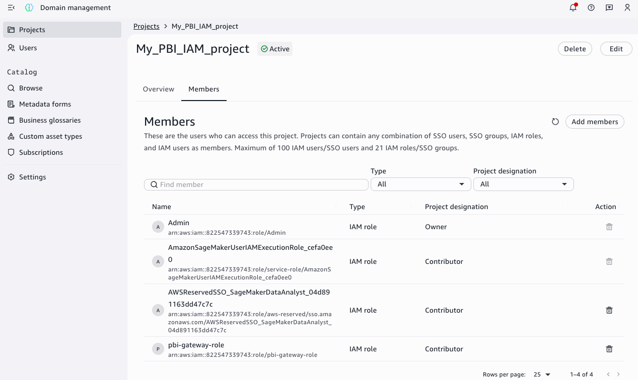
Catalog Federation supports OAuth or custom authentication. For details on using OAuth refer to Federate to Snowflake Iceberg Catalog.

For this post, we use custom authentication and generate access token using PAT. Replace role_name with the principal role and token_value with the principal’s Programmatic Access Token.

curl --location 'https://<accountidentifier>.snowflakecomputing.com/polaris/api/catalog/v1/oauth/tokens' \
--header 'Content-Type: application/x-www-form-urlencoded' \
--data-urlencode 'grant_type=client_credentials' \
--data-urlencode 'scope=session:role:<role_name>' \
--data-urlencode 'client_secret=<token_value>'

Note down the access token that is generated.

Step 3: Enable catalog federation

With access control configured and authentication credentials in hand, AWS Glue Catalog Federation can now connect to and access Snowflake’s Horizon Catalog.

Optional: Snowflake Open Catalog configuration

If you prefer to use Snowflake Open Catalog for Iceberg external access instead, refer to Sync a Snowflake-managed table with Snowflake Open Catalog for alternative setup instructions.

Setup Glue Catalog federation with Snowflake Horizon Catalog

Create a secret on AWS Secrets Manager

Log in to AWS console using the IAM role that has access to AWS Secrets Manager. Open Secrets Manager:

  • Choose Store a new secret and select Other type of secret for the secret type.
  • Set the key-value pair:
    • Key: BEARER_TOKEN
    • Value: The access token noted earlier
  • Choose Next and provide the secret name as horizon-secret.
  • Complete the setup by choosing Store.

Alternatively, you can use the CLI to create the secret by running the following command.

Replace your-access-token and your-region with your actual values:

aws secretsmanager create-secret \
    --name horizon-secret \
    --description "Snowflake Horizon access token" \
    --secret-string '{
        "BEARER_TOKEN": "your-access-token"
    }' \
    --region your-region

Create IAM role for catalog federation

As the catalog owner of a federated catalog in AWS Glue Data Catalog, you can use Lake Formation to implement comprehensive access controls for your data teams:

Access control options

You can implement access controls at different granularity levels depending on your governance needs:

  • Coarse-grained: Table-level permissions
  • Fine-grained: Column-level, row-level, and cell-level filtering
  • Tag-based: Dynamic access based on data classification tags

Lake Formation requires an IAM role with permissions to access the underlying S3 locations of your external catalog.

Create an IAM role that enables the Glue Connection to access AWS Secrets Manager, VPC configurations (optional) and Lake formation to manage credential vending for S3 bucket/prefix.

Required permissions

  1. Secrets Manager access: The Glue connection requires permissions to retrieve secret values from Secrets Manager for OAuth tokens stored for your Snowflake service connection.
  2. Amazon Virtual Private Cloud (VPC) Access (optional): When using VPC endpoints to restrict connectivity to your Snowflake Open Catalog account, the Glue connection needs permissions to describe and use VPC network interfaces. This configuration ensures secure, controlled access to both your stored credentials and network resources while maintaining proper isolation through VPC endpoints.
  3. S3 bucket and AWS Key Management Service (KMS) key permission: The Glue connection requires S3 permissions to read certificates if used in the connection setup. Additionally, Lake Formation requires read permissions on the bucket/prefix where the remote catalog table data resides. If the data is encrypted using a KMS key, additional KMS permissions are required.

Setup steps:

Run the following command using AWS CLI by replacing the placeholder with your setup information:

Create a JSON file (e.g., trust-policy.json) with the following structure:

{
    "Version": "2012-10-17",
    "Statement": [
        {
            "Effect": "Allow",
            "Principal": {
                "Service": ["glue.amazonaws.com","lakeformation.amazonaws.com"]
            },
            "Action": "sts:AssumeRole"
        }
    ]
}

Use the aws iam create-role command, referencing the trust policy file:

aws iam create-role \
    --role-name LFDataAccessRole \
    --assume-role-policy-document file://<path_file_downloaded>/trust-policy.json 

First, create a JSON file (such as, permissions-policy.json) for the permissions:


{
"Version": "2012-10-17",
    "Statement": [
        {
            "Effect": "Allow",
            "Action": [
                "secretsmanager:GetSecretValue",
                "secretsmanager:DescribeSecret"
            ],
            "Resource": [
                "<secrets manager ARN>"
            ]
        },
        {
            "Effect": "Allow",
            "Action": [
                "ec2:CreateNetworkInterface",
                "ec2:DeleteNetworkInterface",
                "ec2:DescribeNetworkInterfaces"
            ],
            "Resource": "*",
            "Condition": {
                "ArnEquals": {
                    "ec2:Vpc": "arn:aws:ec2:region:account-id:vpc/<vpc-id>", 
                    "ec2:Subnet": [ 
                        "arn:aws:ec2:region:account-id:subnet/<subnet-id>"
                    ]
                }
            }
        },
        {
           # Required when using custom cert to sign requests.
            "Effect": "Allow",
            "Action": [
                "s3:GetObject"
            ],
            "Resource": [
                "arn:aws:s3:::<bucketname>/<certpath>"
            ]
        },
        { # Required when using customer managed encryption key for s3 
            "Effect": "Allow",
            "Action": [
                "kms:decrypt",
                "kms:encrypt"
            ],
            "Resource": [
                "<kmsKey>"
            ]
        }
    ]
}

Then, attach it to the role:

aws iam put-role-policy \
--role-name LFDataAccessRole \
--policy-name myaccesspolicies \
--policy-document file://<path_file_downloaded>/permissions- policy.json

Create federated catalog in Glue Data Catalog

AWS Glue supports the SNOWFLAKEICEBERGRESTCATALOG connection type for connecting Glue Data Catalog with Snowflake Horizon Catalog and Snowflake Open Catalog. This Glue connector supports OAuth2 authentication and includes additional configuration parameters like CASING_TYPE to customize how AWS Glue Data Catalog discovers metadata in the Snowflake Horizon Catalog accounts.

Log in to your AWS console as a data lake admin and open the AWS Lake Formation console.

  1. Choose Catalog in the left navigation pane and select Create catalog.
  2. Choose the data source as Snowflake Horizon Catalog.
    AWS Lake Formation console screenshot showing Step 1 of catalog creation wizard with five federation type options, Snowflake Horizon Catalog selected.
  3. Provide the following information:
    • Name: Name of the federated catalog in Glue Catalog. For this post, we use federated_lakehousedb
    • Catalog name in Snowflake: Catalog name existing in Snowflake Horizon Catalog, this should match exact name in Horizon catalog. For this post, we use LAKEHOUSEDB
    • For Connection details, choose New connection configurations:
      • Connection name: Name for the glue connection. For this post, we use federatedconnection1.
      • Workspace URL: Horizon IRC url (format: https://<account_identifier>.snowflakecomputing.com)
      • Casing type: choose Uppercase only
      • Authentication:
        • Authentication type: choose Custom. Alternatively, you can select OAuth2 authentication. For Custom authentication, an access token is created, refreshed, and managed by the customer’s application or system and stored using AWS Secrets Manager.
        • OAuth Secret: Provide the secret manager ARN that was created in the previous step.
  • If you have AWS PrivateLink setup and/or a proxy setup, you can provide network details under Settings for network configurations (optional).
  • For Register Glue connection with Lake Formation:
    • Choose the IAM role created earlier(LFDataAccessRole) to manage data access using Lake Formation.

To test the connection, choose Run test. After the connection information is validated, it shows as successful.

Green success banner displaying "Connection test successful" with checkmark icon, confirming valid AWS configuration.

You can now create the catalog by selecting Create catalog.

Alternatively, you can use AWS CLI to create connection and catalog using example commands:

aws glue create-connection \
--connection-input '{
"Name": "federatedconnection1",
"ConnectionType": "SNOWFLAKEICEBERGRESTCATALOG",
"ConnectionProperties": {
    "INSTANCE_URL": "<your-snowflake-account-URL>",
    "ROLE_ARN": "< ARN_of_LFDataAccessRole>",
    "CATALOG_CASING_FILTER": "UPPERCASE_ONLY"
},
"AuthenticationConfiguration": {
    "AuthenticationType": "CUSTOM",
    "SecretArn": "arn:aws:secretsmanager:<your-aws-region>:<your-aws-account-id>:secret:horizon-secret"
}
}' \
--region <your-aws-region>
aws lakeformation register-resource \
    --resource-arn <ARN_of_federatedconnection1_connection> \
    --role-arn <ARN_of_LFDataAccessRole> \
    --with-federation \
    --with-privileged-access \
    --region <your-aws-region>
aws glue create-catalog \
    --name federated_lakehousedb \
    --catalog-input '{
    "FederatedCatalog": {
        "Identifier": "LAKEHOUSEDB",
        "ConnectionName": “federatedconnection1 "
    },
    "CreateTableDefaultPermissions": [],
    "CreateDatabaseDefaultPermissions": []
}'

After the catalog is created, the Horizon databases and tables are listed under the federated catalog.

You can implement fine grained access control on the tables by applying row/column filter using Lake Formation.

Query the data using Athena query editor:

Open the Amazon Athena console and run the following query to access the federated Horizon table:

SELECT * FROM "public"."customer" limit 10;

Clean up

To clean up your resources, complete the following steps:

  1. Drop the Snowflake Database with Cascade.
  2. Drop External Volume created for Iceberg Tables on S3.
  3. Drop the resources in Glue Data Catalog and Lake Formation created for this post.
  4. Delete the IAM roles and S3 buckets used for this post.
  5. Delete any VPC, KMS keys if used for this post setup.

Conclusion

In this post, we demonstrated how to establish a secure connection between AWS Analytics services and Snowflake Horizon Catalog, enabling you to access your data from a single connected and governed view. You learned how to:

  • Configure catalog federation between AWS Glue Data Catalog and Snowflake Horizon Catalog
  • Set up OAuth2 authentication for secure access
  • Grant access to Iceberg table in Snowflake Horizon Catalog using AWS Lake Formation
  • Query federated tables using Amazon Athena

You can follow the same steps to establish a secure connection with open-source catalog options such as Snowflake Open Catalog, a managed service for Apache Iceberg. Remember to clean up any resources you created while following this tutorial to avoid ongoing charges.

To further explore this solution in your environment, consider the following resources:

These resources can help you to implement and optimize this integration pattern for your specific use case. As you begin this journey, remember to start small, validate your architecture with test data, and gradually scale your implementation based on your organization’s needs. Stay tuned for future workshops and resources.


About the authors


Andries Engelbrecht

Andries Engelbrecht

Andries is a Principal Partner Solutions Engineer at Snowflake working with AWS. He supports product and service integrations, as well the development of joint solutions with AWS. Andries has over 25 years of experience in the field of data and analytics.

Nidhi Gupta

Nidhi Gupta

Nidhi is a Senior Partner Solutions Architect at AWS, specializing in data analytics and AI. She helps customers and partners build and optimize Snowflake workloads on AWS. Nidhi has extensive experience leading development, production releases and deployments, with focus on Data, AI, ML, generative AI, and Advanced Analytics.

Srividya Parthasarathy

Srividya Parthasarathy

Srividya is a Senior Big Data Architect on the AWS Lake Formation team. She works with the product team and customers to build robust features and solutions for their analytical data platform. She enjoys building data mesh solutions and sharing them with the community.

Pratik Das

Pratik Das

Pratik is a Senior Product Manager with AWS Lake Formation. He is passionate about all things data and works with customers to understand their requirements and build delightful experiences. He has a background in building data-driven solutions and machine learning systems.


Amazon S3 Storage Lens adds performance metrics, support for billions of prefixes, and export to S3 Tables

Post Syndicated from Veliswa Boya original https://aws.amazon.com/blogs/aws/amazon-s3-storage-lens-adds-performance-metrics-support-for-billions-of-prefixes-and-export-to-s3-tables/

Today, we’re announcing three new capabilities for Amazon S3 Storage Lens that give you deeper insights into your storage performance and usage patterns. With the addition of performance metrics, support for analyzing billions of prefixes, and direct export to Amazon S3 Tables, you have the tools you need to optimize application performance, reduce costs, and make data-driven decisions about your Amazon S3 storage strategy.

New performance metric categories
S3 Storage Lens now includes eight new performance metric categories that help identify and resolve performance constraints across your organization. These are available at organization, account, bucket, and prefix levels. For example, the service helps you identify small objects in a bucket or prefix that can  slow down application performance. This can be mitigated by batching small objects or using the Amazon S3 Express One Zone storage class for higher performance small object workloads.

To access the new performance metrics, you need to enable performance metrics in the S3 Storage Lens advanced tier when creating a new Storage Lens dashboard or editing an existing configuration.

Metric category Details Use case Mitigation
Read request size Distribution of read request sizes (GET) by day Identify dataset with small read request patterns that slow down performance Small request: Batch small objects or use Amazon S3 Express One Zone for high-performance small object workloads
Write request size Distribution of write request sizes (PUT, POST, COPY, and UploadPart) by day Identify dataset with small write request patterns that slow down performance Large request: Parallelize requests, use MPU or use AWS CRT
Storage size Distribution of object sizes Identify dataset with small small objects that slow down performance Small object sizes: Consider bundling small objects
Concurrent PUT 503 errors Number of 503s due to concurrent PUT operation on same object Identify prefixes with concurrent PUT throttling that slow down performance For single writer, modify retry behavior or use Amazon S3 Express One Zone. For multiple writers, use consensus mechanism or use Amazon S3 Express One Zone
Cross-Region data transfer Bytes transferred and requests sent across Region, in Region Identify potential performance and cost degradation due to cross-Region data access Co-locate compute with data in the same AWS Region
Unique objects accessed Number or percentage of unique objects accessed per day Identify datasets where small subset of objects are being frequently accessed. These can be moved to higher performance storage tier for better performance Consider moving active data to Amazon S3 Express One Zone or other caching solutions
FirstByteLatency (existing Amazon CloudWatch metric) Daily average of first byte latency metric The daily average per-request time from the complete request being received to when the response starts to be returned
TotalRequestLatency (existing Amazon CloudWatch metric) Daily average of Total Request Latency The daily average elapsed per request time from the first byte received to the last byte sent

How it works
On the Amazon S3 console I choose Create Storage Lens dashboard to create a new dashboard. You can also edit an existing dashboard configuration. I then configure general settings such as providing a Dashboard name, Status, and the optional Tags. Then, I choose Next.


Next, I define the scope of the dashboard by selecting Include all Regions and Include all buckets and specifying the Regions and buckets to be included.


I opt in to the Advanced tier in the Storage Lens dashboard configuration, select Performance metrics, then choose Next.


Next, I select Prefix aggregation as an additional metrics aggregation, then leave the rest of the information as default before I choose Next.


I select the Default metrics report, then General purpose bucket as the bucket type, and then select the Amazon S3 bucket in my AWS account as the Destination bucket. I leave the rest of the information as default, then select Next.


I review all the information before I choose Submit to finalize the process.


After it’s enabled, I’ll receive daily performance metrics directly in the Storage Lens console dashboard. You can also choose to export report in CSV or Parquet format to any bucket in your account or publish to Amazon CloudWatch. The performance metrics are aggregated and published daily and will be available at multiple levels: organization, account, bucket, and prefix. In this dropdown menu, I choose the % concurrent PUT 503 error for the Metric, Last 30 days for the Date range, and 10 for the Top N buckets.


The Concurrent PUT 503 error count metric tracks the number of 503 errors generated by simultaneous PUT operations to the same object. Throttling errors can degrade application performance. For a single writer, modify retry behavior or use higher performance storage tier such as Amazon S3 Express One Zone to mitigate concurrent PUT 503 errors. For multiple writers scenario, use a consensus mechanism to avoid concurrent PUT 503 errors or use higher performance storage tier such as Amazon S3 Express One Zone.

Complete analytics for all prefixes in your S3 buckets
S3 Storage Lens now supports analytics for all prefixes in your S3 buckets through a new Expanded prefixes metrics report. This capability removes previous limitations that restricted analysis to prefixes meeting a 1% size threshold and a maximum depth of 10 levels. You can now track up to billions of prefixes per bucket for analysis at the most granular prefix level, regardless of size or depth.

The Expanded prefixes metrics report includes all existing S3 Storage Lens metric categories: storage usage, activity metrics (requests and bytes transferred), data protection metrics, and detailed status code metrics.

How to get started
I follow the same steps outlined in the How it works section to create or update the Storage Lens dashboard. In Step 4 on the console, where you select export options, you can select the new Expanded prefixes metrics report. Thereafter, I can export the expanded prefixes metrics report in CSV or Parquet format to any general purpose bucket in my account for efficient querying of my Storage Lens data.


Good to know
This enhancement addresses scenarios where organizations need granular visibility across their entire prefix structure. For example, you can identify prefixes with incomplete multipart uploads to reduce costs, track compliance across your entire prefix structure for encryption and replication requirements, and detect performance issues at the most granular level.

Export S3 Storage Lens metrics to S3 Tables
S3 Storage Lens metrics can now be automatically exported to S3 Tables, a fully managed feature on AWS with built-in Apache Iceberg support. This integration provides daily automatic delivery of metrics to AWS managed S3 Tables for immediate querying without requiring additional processing infrastructure.

How to get started
I start by following the process outlined in Step 5 on the console, where I choose the export destination. This time, I choose Expanded prefixes metrics report. In addition to General purpose bucket, I choose Table bucket.

The new Storage Lens metrics are exported to new tables in an AWS managed bucket aws-s3.


I select the expanded_prefixes_activity_metrics table to view API usage metrics for expanded prefix reports.


I can preview the table on the Amazon S3 console or use Amazon Athena to query the table.


Good to know
S3 Tables integration with S3 Storage Lens simplifies metric analysis using familiar SQL tools and AWS analytics services such as Amazon Athena, Amazon QuickSight, Amazon EMR, and Amazon Redshift, without requiring a data pipeline. The metrics are automatically organized for optimal querying, with custom retention and encryption options to suit your needs.

This integration enables cross-account and cross-Region analysis, custom dashboard creation, and data correlation with other AWS services. For example, you can combine Storage Lens metrics with S3 Metadata to analyze prefix-level activity patterns and identify objects in prefixes with cold data that are eligible for transition to lower-cost storage tiers.

For your agentic AI workflows, you can use natural language to query S3 Storage Lens metrics in S3 Tables with the S3 Tables MCP Server. Agents can ask questions such as ‘which buckets grew the most last month?’ or ‘show me storage costs by storage class’ and get instant insights from your observability data.

Now available
All three enhancements are available in all AWS Regions where S3 Storage Lens is currently offered (except the China Regions and AWS GovCloud (US)).

These features are included in the Amazon S3 Storage Lens Advanced tier at no additional charge beyond standard advanced tier pricing. For the S3 Tables export, you pay only for S3 Tables storage, maintenance, and queries. There is no additional charge for the export functionality itself.

To learn more about Amazon S3 Storage Lens performance metrics, support for billions of prefixes, and export to S3 Tables, refer to the Amazon S3 user guide. For pricing details, visit the Amazon S3 pricing page.

Veliswa Boya.

Amazon FSx for NetApp ONTAP now integrates with Amazon S3 for seamless data access

Post Syndicated from Veliswa Boya original https://aws.amazon.com/blogs/aws/amazon-fsx-for-netapp-ontap-now-integrates-with-amazon-s3-for-seamless-data-access/

Today, we’re announcing the ability to access your data in Amazon FSx for NetApp ONTAP file systems using Amazon Simple Storage Service (Amazon S3). With this capability, you can use your enterprise file data to augment generative AI applications with Amazon Bedrock Knowledge Bases for Retrieval Augmented Generation (RAG), train machine learning (ML) models with Amazon SageMaker, generate insights with Amazon S3 integrated third-party services, use comprehensive research capabilities in AI-powered business intelligence (BI) tools such as Amazon Quick Suite, and run analyses using Amazon S3 based cloud-native applications, all while your file data continues to reside in your FSx for NetApp ONTAP file system.

Amazon FSx for NetApp ONTAP is the first and fully AWS managed NetApp ONTAP file system in the cloud to migrate on-premises applications that rely on NetApp ONTAP or other network-attached storage (NAS) appliances to AWS without having to change how you manage your data. FSx for NetApp ONTAP provides the popular capabilities, high performance, and data management APIs of ONTAP file systems with the added benefits of the AWS Cloud, such as simplified management, on-demand scaling, and seamless integration with other AWS services.

Over the years, AWS has developed a broad range of industry-leading AI, ML, and analytics services and applications that work with data in Amazon S3 that organizations use to innovate faster, discover new insights, and make even better data-driven decisions. However, some organizations want to use these services with their enterprise file data stored in NetApp ONTAP or other NAS appliances.

How to get started
You can create and attach an S3 Access Point to your FSx for ONTAP file system using the Amazon FSx console, the AWS Command Line Interface (AWS CLI), or the AWS SDK.

I have an existing FSx for ONTAP file system demo-create-s3access which I created by following the steps in the Creating file systems in the FSx for ONTAP documentation. Using the Amazon FSx console I now choose the file system ID fs-0c45b011a7f071d70 to access the full details of the file system.

I’ll attach the access point to the volume of the file system. I choose the volume vol1 and then select Create S3 Access Point from the Actions dropdown menu.


I enter details such as the access point name, the type of file system user identity and the network configuration, then choose Create s3 Access Point to finalize the process.


After it’s created, the access point my-s3-accesspoint is ready to allow access to the file data stored in my file system demo-create-s3access from Amazon S3. Amazon Access Points are S3 endpoints that can be attached to Amazon FSx volumes and used to perform Amazon S3 object operations.


I can now bring proprietary data stored in the file system demo-create-s3access to Amazon S3 for use in applications that work with Amazon S3 while my file data continues to reside in the FSx for NetApp ONTAP file system using the access point my-s3-accesspoint (this data remains accessible through the file protocols).

For the walkthrough in this post, I’ll integrate with Quick Suite.

Integrating decades of enterprise file data with the latest AI powered BI tools on AWS
In the Quick Suite Console, in the left navigation pane, I choose Connections, then select Integrations. Before you begin, make sure that you have the correct permissions to the Amazon S3 AWS resource. You can control the AWS resources that Quick Suite can access by following the Amazon Quick Suite user guide.


After I’ve selected the Amazon S3 integration I enter my Amazon S3 Access Point alias as the S3 bucket URL, leave the rest of the information as default, then choose Create and continue.


I finalize the process by providing the Name of the knowledge base, the Description, then choose Create.


After the knowledge base has been created it’s automatically synchronized, it’s now available for interaction.


I want to learn more about the AWS European Sovereign Cloud so I’ve updated the file system (accessed through the S3 Access Point my-s3-accesspoin-iyytkgz83djdjj7abn3u711supfgkuse1b-ext-s3alias) with the AWS whitepaper on this topic. In the chat in Amazon Quick Suite. I start asking the first question “do we have any documentation on the europe sovereignty cloud?“. To answer my question, the chat agent accesses and analyzes various types of data sources I have permission to use, including uploaded files in my current conversation, spaces I have access to, knowledge bases from my integrations, and more.
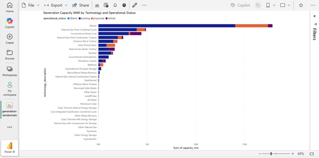
When I verify the source, I see that the document I uploaded to my file system is listed as one of the sources.

Other use cases of Amazon S3 Access Points for Amazon FSx for NetApp ONTAP
Earlier, we looked at use cases such as connecting an organization’s proprietary file data to Amazon Quick Suite for advanced business intelligence. Additionally, Amazon S3 Access Points for Amazon FSx for NetApp ONTAP can be used to seamlessly integrate enterprise file data with comprehensive analytics services, such as Amazon Athena for serverless SQL queries or AWS Glue for ETL processing, to name a few.

Amazon S3 Access Points for Amazon FSx for NetApp ONTAP are also suitable for data access from serverless compute workloads that are cloud-native with containerized microservices that require flexible access to shared enterprise datasets, such as configuration files, reference data, content libraries, model artifacts, and application assets.
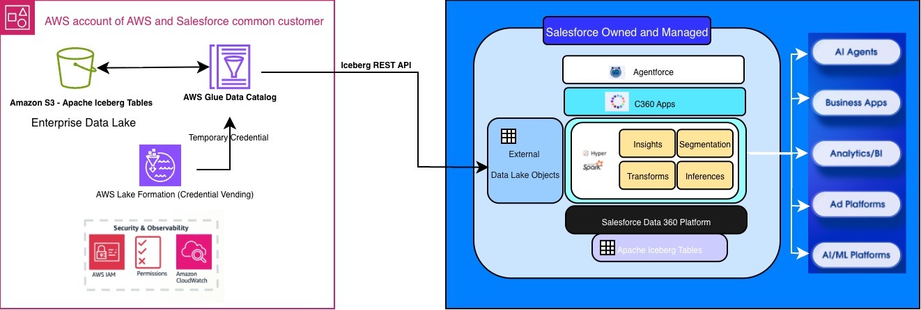
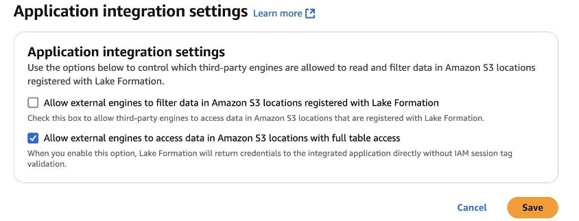
Now available
You can get started today using the Amazon FSx console, AWS CLI, or AWS SDK to attach Amazon S3 Access Points to your Amazon FSx for NetApp ONTAP file systems. The feature is available in the following AWS Regions: Africa (Cape Town), Asia Pacific (Hong Kong, Hyderabad, Jakarta, Melbourne, Mumbai, Osaka, Seoul, Singapore, Sydney, Tokyo), Canada (Central, Calgary), Europe (Frankfurt, Ireland, London, Milan, Paris, Spain, Stockholm, Zurich), Israel (Tel Aviv), Middle East (Bahrain, UAE), South America (Sao Paulo), US East (N. Virginia, Ohio), and US West (N. California Oregon). You’re billed by Amazon S3 for the requests and data transfer costs through your S3 Access Point, in addition to your standard Amazon FSx charges. Learn more on the Amazon FSx for NetApp ONTAP pricing page.

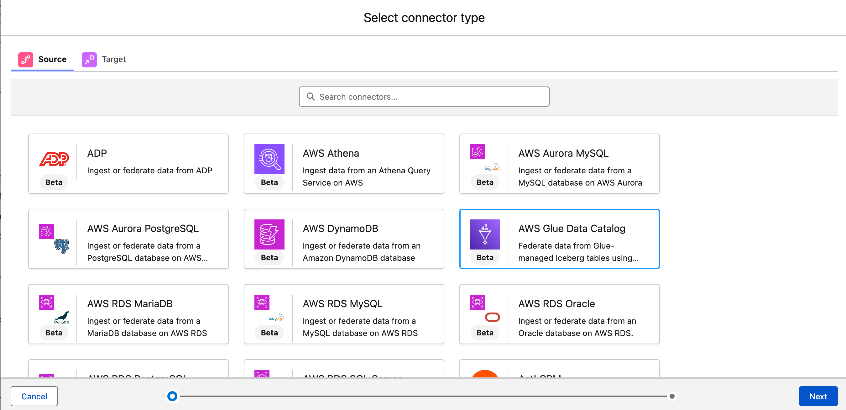
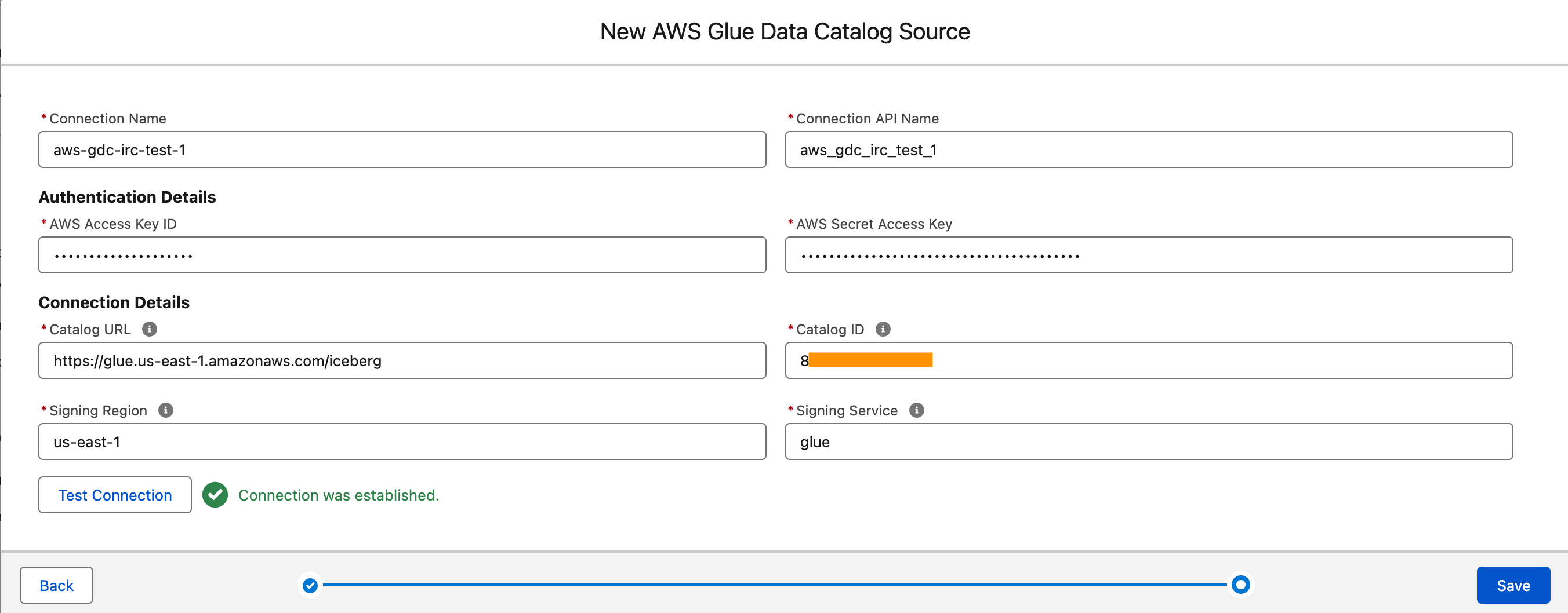
PS: Writing a blog post at AWS is always a team effort, even when you see only one name under the post title. In this case, I want to thank Luke Miller, for his expertise and generous help with technical guidance, which made this overview possible and comprehensive.

Veliswa Boya.

Orchestrating big data processing with AWS Step Functions Distributed Map

Post Syndicated from Biswanath Mukherjee original https://aws.amazon.com/blogs/compute/orchestrating-big-data-processing-with-aws-step-functions-distributed-map/

Developers seek to process and enrich semi-structured big data datasets with durably orchestrated network-based workflows. For example, during quarterly earnings season, finance organizations run thousands of market simulations simultaneously to provide timely insights for scenario planning or risk management—these workloads require coordination between raw datasets and on-premise servers to provide the latest market information.
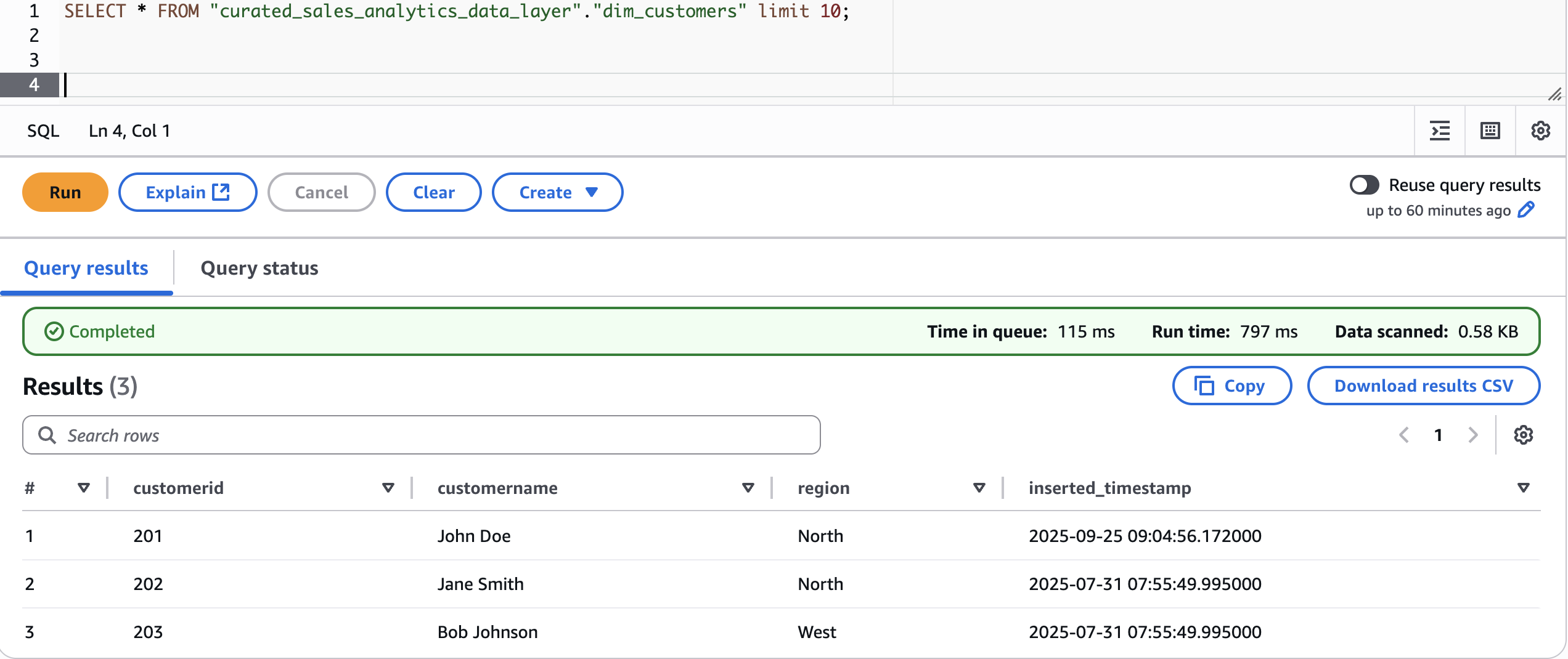
AWS Step Functions is a visual workflow service capable of orchestrating over 14,000 API actions from over 220 AWS services to build distributed applications. Now, Step Functions Distributed Map streamlines big data dataset transformation by processing Amazon Athena data manifest and Parquet files directly. Using its Distributed Map feature, you can process large scale datasets by running concurrent iterations across data entries in parallel. In Distributed mode, the Map state processes the items in the dataset in iterations called child workflow executions. You can specify the number of child workflow executions that can run in parallel. Each child workflow execution has its own, separate execution history from that of the parent workflow. By default, Step Functions runs 10,000 parallel child workflow executions in parallel.
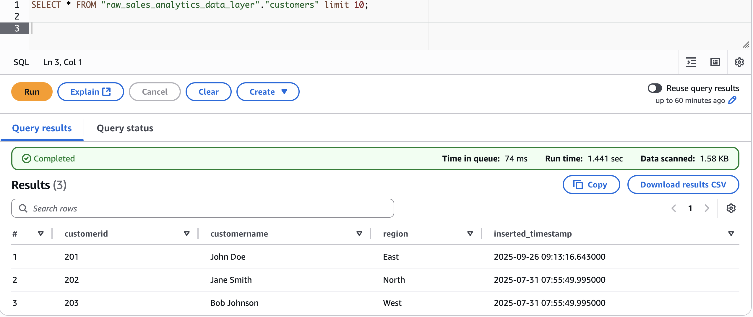
Distributed Map can process AWS Athena data manifest and Parquet files directly, eliminating the need for custom pre-processing. You also now have visibility into your Distributed Map usage with new Amazon CloudWatch metrics: Approximate Open Map Runs Count, Open Map Run Limit, and Approximate Map Runs Backlog Size.

In this post, you’ll learn how to use AWS Step Functions Distributed Map to process Athena data manifest and Parquet files through a step-by-step demonstration.

This post is part of a series of post about AWS Step Functions Distributed Map:

Use case: IoT sensor data processing

You’ll build a sample application that demonstrates processing IoT sensor data in Parquet format using Step Functions Distributed Map. These Parquet data files and a manifest file containing the list of the data files are exported from Athena. The data temperature, humidity, and lbattery level from different devices. The following table shows sample of sensor data:

Example IoT sensor data

Example IoT sensor data

Your objective is to use the Athena data manifest file, get the list of Parquet files, and iterate over the data in the files to detect anomalies and also stream the processed data through Amazon Kinesis Data Firehose to an Amazon S3 bucket for further analytics using Athena queries. Following is the criteria to detect anomaly:

  • Low battery conditions: less than 20%
  • Humidity anomalies: more than 95% or less than 5%
  • Temperature spikes: more than 35°C or less than -10°C

The following diagram represents the AWS Step Functions state machine:

Parquet files processing workflow

Parquet files processing workflow

  1. The Distributed Map runs an Athena query which generates Parquet data files and an Athena manifest file (csv). The manifest file contains the list of Parquet data files.
  2. Distributed Map processes these Parquet data files in parallel using child workflow executions. You can control the number of child workflow executions that can run in parallel using MaxConcurrency parameter. See Step Functions service quotas to learn more about concurrency limits.
  3. Each child workflow execution invokes an AWS Lambda function to process the respective Parquet file. The Lambda function processes individual sensor readings and detects anomalies according to the preceeding logic and returns a processed sensor data summary response.
  4. The child workflow sends the summary response record to Amazon Kinesis firehose stream which stores the results in a specified Amazon S3 results bucket.

The following Athena Start QueryExecution state runs an UNLOAD query to generate data files in Parquet format and a manifest file in CSV. The output will be stored in the S3 bucket specified in the UNLOAD query and the manifest file will be stored in the S3 bucket configured for the Athena workgroup.

{
  "QueryLanguage": "JSONata",
  "States": {
	   "Athena StartQueryExecution": {
	    "Type": "Task",
	        "Resource": "arn:aws:states:::athena:startQueryExecution.sync",
	        "Arguments": {
		"QueryString": "UNLOAD (WRITE_YOUR_SELECT_QUERY_HERE) TO 'S3_URI_FOR_STORING_DATA_OBJECT' WITH (format = 'JSON')",
		"WorkGroup": "primary"
	},
	"Output": {
	"ManifestObjectKey": "{% $join([$states.result.QueryExecution.ResultConfiguration.OutputLocation, '-manifest.csv']) %}"
},
“Next”: “Next State”
…
}

The following ItemReader is configured to use a manifest type of “ATHENA_DATA” with “PARQUET” data input.

{
  "QueryLanguage": "JSONata",
  "States": {
    ...
    "Map": {
        ...
        "ItemReader": {
        	"Resource": "arn:aws:states:::s3:getObject",
   	"ReaderConfig": {
      		"ManifestType": "ATHENA_DATA",
      		"InputType": "PARQUET"
   	},
   	"Arguments": {
      		"Bucket":"Bucket": "{% $split($substringAfter($states.input.ManifestObjectKey, 's3://'), '/')[0] %}",,
      		"Key": "{% $substringAfter($substringAfter($states.input.ManifestObjectKey, 's3://'), '/') %}"
   	}
	    },
        ...
    }
}

Additional supported InputType options are CSV and JSONL. All objects referenced in a single manifest file must have the same InputType format. You specify the Amazon S3 bucket location of Athena manifest CSV file under Arguments.

The context object contains information in a JSON structure about your state machine and execution. Your workflows can reference the context object in a JSONata expression with $states.context.

Within a Map state, the Context object includes the following data:

"Map": {
   "Item": {
      "Index" : Number,
      "Key"   : "String", // Only valid for JSON objects
      "Value" : "String",
      "Source": "String"
   }
}

For each Map state iteration, Index contains the index number for the array item that is being currently processed, Key is available only when iterating over JSON objects, Value contains the array item being processed, and Source contains one of the following:

  • For state input, the value will be : STATE_DATA
  • For Amazon S3 LIST_OBJECTS_V2 with Transformation=NONE, the value will show the S3 URI for the bucket. For example: S3://amzn-s3-demo-bucket.
  • For all the other input types, the value will be the Amazon S3 URI. For example: S3://amzn-s3-demo-bucket/object-key.

Using this newly introduced Source field in the context object, you can connect the child executions with the source object.

Prerequisites

Set up the state machine and sample data

Run the following steps to deploy the Step Functions state machine.

  1. Clone the GitHub repository in a new folder and navigate to the project root folder.
    git clone https://github.com/aws-samples/sample-stepfunctions-athena-manifest-parquet-file-processor.git
    cd sample-stepfunctions-athena-manifest-parquet-file-processor

  2. Run the following command to install required Python dependencies for the Lambda function.
    python3 -m venv .venv
    source .venv/bin/activate
    python3 -m pip install -r requirements.txt

  3. Build the application.
    sam build

  4. Deploy the application
    sam deploy --guided

  5. Enter the following details:
    • Stack name: The CloudFormation stack name (for example, sfn-parquet-file-processor)
    • AWS Region: A supported AWS Region (for example, us-east-1)
    • Keep rest of the components to default values.

    Note the outputs from the AWS SAM deploy. You will use them in the subsequent steps.

  6. Run the following command to generate sample data in csv format and upload it to an S3 bucket. Replace <IoTDataBucketName> with the value from sam deploy ouptut.
    python3 scripts/generate_sample_data.py <IoTDataBucketName>

Create the Athena database and tables

Before you can run queries, you must set up an Athena database and table for your data.

  1. From Amazon Athena console, navigate to workgoups, select the workgroup named “primary”. Select Edit from Actions. In the query result configuration section, select the options as follows:
    1. Management of query results – select customer managed
    2. Location of query results – enter s3://<IoTDataBucketName>. Replace <IoTDataBucketName> with the value from sam deploy output.
    3. Choose Save to save the changes to the workgroup
  2. Select Query editor tab and run the following commands to create database and tables
    CREATE DATABASE `iotsensordata`;

  3. Create an Athena table in database iotsensordata that references the S3 bucket containing the raw sensor data. In this case it will be <IoTDataBucketName>. Replace <IoTDataBucketName> with the value from sam deploy output.
    CREATE EXTERNAL TABLE IF NOT EXISTS `iotsensordata`.`iotsensordata` 
    (`deviceid` string, 
    `timestamp` string,
    `temperature` double,
    `humidity` double,
    `batterylevel` double,
    `latitude` double,
    `longitude` double
    )
    ROW FORMAT SERDE 'org.apache.hadoop.hive.serde2.lazy.LazySimpleSerDe'
    WITH SERDEPROPERTIES ('field.delim' = ',')
    STORED AS INPUTFORMAT 'org.apache.hadoop.mapred.TextInputFormat' OUTPUTFORMAT 'org.apache.hadoop.hive.ql.io.HiveIgnoreKeyTextOutputFormat'
    LOCATION 's3://<IoTDataBucketName>/daily-data/'
    TBLPROPERTIES (
     'classification' = 'csv',
     'skip.header.line.count' = '1'
    );

  4. Create an Athena table in database iotsensordata that references the S3 bucket having the analytics results streamed from Kinesis Data Firehose. Replace <IoTAnalyticsResultsBucket> with value from sam deploy output. And replace <year> with the current year (e.g 2025).
    CREATE EXTERNAL TABLE IF NOT EXISTS iotsensordata.iotsensordataanalytics (deviceid string, analysisDate string, readingTimestamp string, readingsCount int, metrics struct< temperature: double, humidity: double, batterylevel: double, latitude: double, longitude: double >, anomalies array <string>, anomalyCount int, healthStatus string, timestamp string )
    ROW FORMAT SERDE 'org.openx.data.jsonserde.JsonSerDe'
    WITH SERDEPROPERTIES ( 'ignore.malformed.json' = 'FALSE', 'dots.in.keys' = 'FALSE', 'case.insensitive' = 'TRUE'
    )
    STORED AS INPUTFORMAT 'org.apache.hadoop.mapred.TextInputFormat' OUTPUTFORMAT 'org.apache.hadoop.hive.ql.io.HiveIgnoreKeyTextOutputFormat'
    LOCATION 's3://<IoTAnalyticsResultsBucket>/<year>/'
    TBLPROPERTIES ('classification' = 'json', 'typeOfData'='file');

Start your state machine

Now that you have data ready and Athena set up for queries, start your state machine to retrieve and process the data.

  1. Run the following command to start execution of the Step Functions. Replace the <StateMachineArn> and <IoTDataBucketName> with the value from sam deploy output..
    aws stepfunctions start-execution \
      --state-machine-arn <StateMachineArn> \
      --input '{ "IoTDataBucketName": "<IoTDataBucketName>"}'

    The Step Functions state machine has the Athena StartQueryExecution state which has an UNLOAD query that generates the sensor data files in a parquet format and a manifest file in CSV format. The manifest will have 5 rows referencing the 5 parquet files. The state machine will process these 5 parquet files in one map run.

  2. Run the following command to get the details of the execution. Replace the executionArn from the previous command.
    aws stepfunctions describe-execution --execution-arn <executionArn>

  3. After you see the status SUCCEEDED, run the following command from Athena query editor to check the processed output from Kinesis Data Firehose that was streamed to S3 bucket referenced by the Athena table created in step 4 of the preceding section.
    SELECT * FROM iotsensordata.iotsensordataanalytics WHERE anomalycount = 1;

If any of the sensor data exceeds the thresholds, the healthstatus attribute will be set to “anomalies_detected”. The workflow produced a summary table of metadata which you can now query for reporting.

Output from Athena Query Editor

Review workflow performance

Using the following observability metrics, you can review key performance behavior of your data processing workflow.
The AWS/States namespace includes the following new metrics for all Step Functions Map Runs.

  • OpenMapRunLimit: This is the maximum number of open Map Runs allowed in the AWS account. The default value is 1,000 runs and is a hard limit. For more information, see Quotas related to accounts.
  • ApproximateOpenMapRunCount: This metric tracks the approximate number of Map Runs currently in progress within an account. Configuring an alarm on this metric using the Maximum statistic with a threshold of 900 or higher can help you take proactive action before reaching the OpenMapRunLimit of 1,000. This metric enables operational teams to implement preventive measures, such as staggering new executions or optimizing workflow concurrency, to maintain system stability and prevent backlog accumulation.
  • ApproximateMapRunBacklogSize: This metric shows up when the ApproximateOpenMapRunCount has reached 1,000 and there are backlogged Map Runs waiting to be executed. Backlogged Map Runs wait at the MapRunStarted event until the total number of open Map Runs is less than the quota.

The following graph shows an example of these new metrics. Use the maximum statistic to visualize these metrics. ApproximateMapRunBacklogSize metrics appear after accounts start getting throttled on the OpenMapRunLimit limit. The OpenMapRun (orange line) is the account hard limit of 1,000 shown as a static line. The ApproximateOpenMapRunCount (violet line) is the current number of active OpenMap runs. The ApproximateMapRunBacklogSize (green line) indicates the map runs waiting in backlog to be processed. When the ApproximateOpenMapRunCount is lower than 1000 (OpenMapRun limit) there are no map runs in backlog. However, when the count reaches the OpenMapRun limit, the backlog of map runs starts to build up. After the active runs complete, the backlog will start to drain out and new runs will begin execution.

Graphed metrics from Amazon CloudWatch

Graphed metrics from Amazon CloudWatch

Clean up

To avoid costs, remove all resources created for this post once you’re done. From the Athena query editor, run the following commands:

DROP TABLE `iotsensordata`.`iotsensordata`;
DROP TABLE `iotsensordata`.`iotsensordataanalytics`;
DROP DATABASE `iotsensordata`;

Run the following commands from the AWS CLI after replacing the <placeholder> variable to delete the resources you deployed for this post’s solution:

aws s3 rm s3://<IoTDataBucketName> --recursive
aws s3 rm s3://<IoTAnalyticsResultsBucketName> --recursive
sam delete

Conclusion

With this update, Distributed Map now supports additional data inputs, so you can orchestrate large-scale analytics and ETL workflows. You can now process Amazon Athena data manifest and Parquet files directly, eliminating the need for custom pre-processing. You also now have visibility into your Distributed Map usage with the following metrics: Approximate Open Map Runs Count, Open Map Run Limit, and Approximate Map Runs Backlog Size.

New input sources for Distributed Map are available in all commercial AWS Regions where AWS Step Functions is available. For a complete list of AWS Regions where Step Functions is available, see the AWS Region Table. The improved observability of your Distributed Map usage with new metrics is available in all AWS Regions. To get started, you can use the Distributed Map mode today in the AWS Step Functions console. To learn more, visit the Step Functions developer guide.

For more serverless learning resources, visit Serverless Land.