All posts by Bharat Gamini

Disaster recovery considerations with Amazon EMR on Amazon EC2 for Spark workloads

Post Syndicated from Bharat Gamini original https://aws.amazon.com/blogs/big-data/disaster-recovery-considerations-with-amazon-emr-on-amazon-ec2-for-spark-workloads/

Amazon EMR is a cloud big data platform for running large-scale distributed data processing jobs, interactive SQL queries, and machine learning (ML) applications using open-source analytics frameworks such as Apache Spark, Apache Hive, and Presto. Amazon EMR launches all nodes for a given cluster in the same Amazon Elastic Compute Cloud (Amazon EC2) Availability Zone to improve performance. During an Availability Zone failure or due to any unexpected interruption, Amazon EMR may not be accessible, and we need a disaster recovery (DR) strategy to mitigate this problem.

Part of architecting a resilient, highly available Amazon EMR solution is the consideration that failures do occur. These unexpected interruptions can be caused by natural disasters, technical failures, and human interactions resulting in an Availability Zone outage. The EMR cluster could also become unreachable due to failure of critical services running on the EMR master node, network issues, or other issues.

In this post, we show you how to architect your Amazon EMR environment for disaster recovery to maintain business continuity with minimum Recovery Time Objective (RTO) during Availability Zone failure or when your EMR cluster is inoperable.

Although various disaster recovery strategies are available in the cloud, we discuss active-active and active-passive DR strategies for Amazon EMR in this post. We focus on a use case for Spark batch workloads where persistent storage is decoupled from Amazon EMR and the EMR cluster is running with a single master node. If the EMR cluster is used for persistent storage, it requires an additional strategy to replicate data from the EMR cluster, which we will cover in subsequent posts.

Prerequisites

To follow along with this post, you should have a knowledge of Amazon Managed Workflows for Apache Airflow (Amazon MWAA) and an understanding of Network Load Balancers.

Solution overview

The following diagram illustrates the solution architecture.

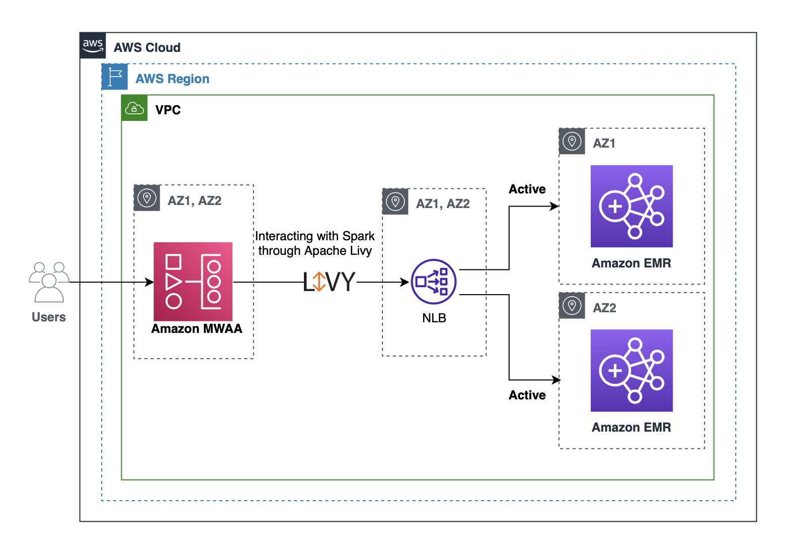
Customers often use Amazon MWAA to submit Spark jobs to an EMR cluster using an Apache Livy REST interface. We can configure Apache Livy to use a Network Load Balancer hostname instead of an Amazon EMR master hostname, so that we don’t need to update Livy connections from Amazon MWAA whenever a new cluster is created or stopped. You can register Network Load Balancer target groups with multiple EMR cluster master nodes for an active-active setup. In the case of an active-passive setup, we can create a new EMR cluster when a failure is detected and register the new EMR master with the Network Load Balancer target group. The Network Load Balancer automatically performs health checks and distributes requests to healthy targets. With this solution, we can maintain business continuity when an EMR cluster isn’t reachable due to Availability Zone failure or when the cluster is unhealthy due to any other reason.

Active-active DR strategy

An active-active DR setup focuses on running two EMR clusters with identical configuration in two different Availability Zones. To reduce the running costs of two active EMR clusters, we can launch both clusters with minimum capacity, and managed scaling automatically scales the cluster based on the workload. EMR managed scaling only launches instances when there is demand for resources and stops the unneeded instances when the work is finished. With this strategy, we can reduce our recovery time to near zero with optimal cost. This active-active DR strategy is suitable when businesses want to have near-zero downtime with automatic failover for your analytics workloads.

In the following section, we walk through the steps to implement the solution and provide references to related resources that provide more detailed guidance.

Create EMR clusters

We create two EMR clusters in different Availability Zones within the same Region of your choice. Use the following AWS Command Line Interface (AWS CLI) command and modify or add required configurations as per your needs:

aws emr create-cluster \
  --name "<emr-cluster-az-a>" \
  --release-label emr-6.4.0 \
  --log-uri "s3://<your-log-bucket>" \
  --applications Name=Spark Name=Livy \
  --ec2-attributes "KeyName=<your-key-name>,SubnetId=<private-subnet-in-az-a>" \
  --instance-groups InstanceGroupType=MASTER,InstanceCount=1,InstanceType=m4.large InstanceGroupType=CORE,InstanceCount=1,InstanceType=m4.large \
  --use-default-roles

We can create the cluster with EMR managed scaling, which lets you automatically increase or decrease the number of instances or units in your cluster based on workload. Amazon EMR continuously evaluates cluster metrics to make scaling decisions that optimize your clusters for cost and speed.

Create and configure a Network Load Balancer

You can create a Network Load Balancer using the AWS CLI (see Create a Network Load Balancer using the AWS CLI) or the AWS Management Console (see Create a Network Load Balancer). For this post, we do so on the console.

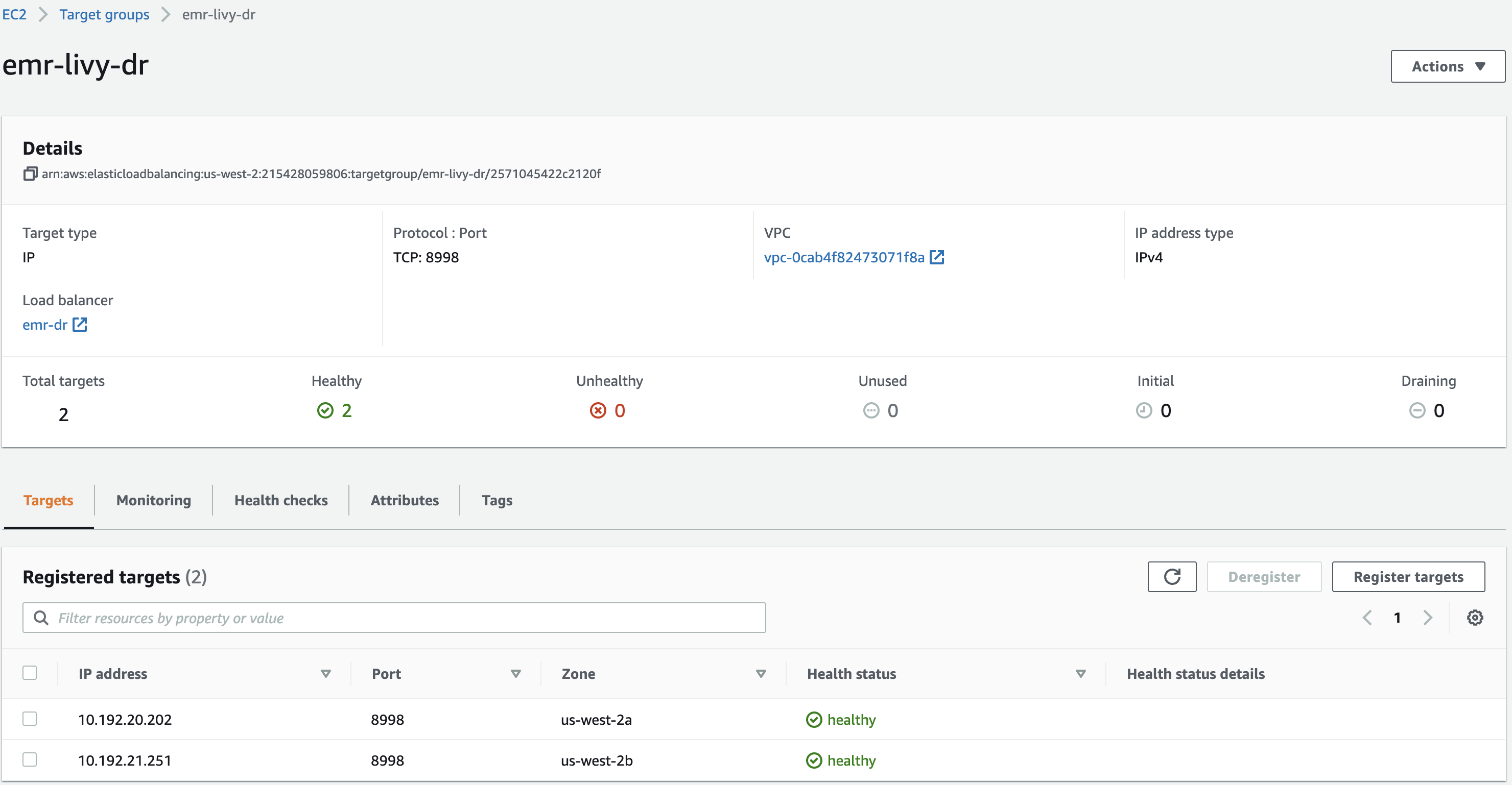
  • Create a target group (emr-livy-dr) and register both EMR clusters’ master IP addresses in the target group.

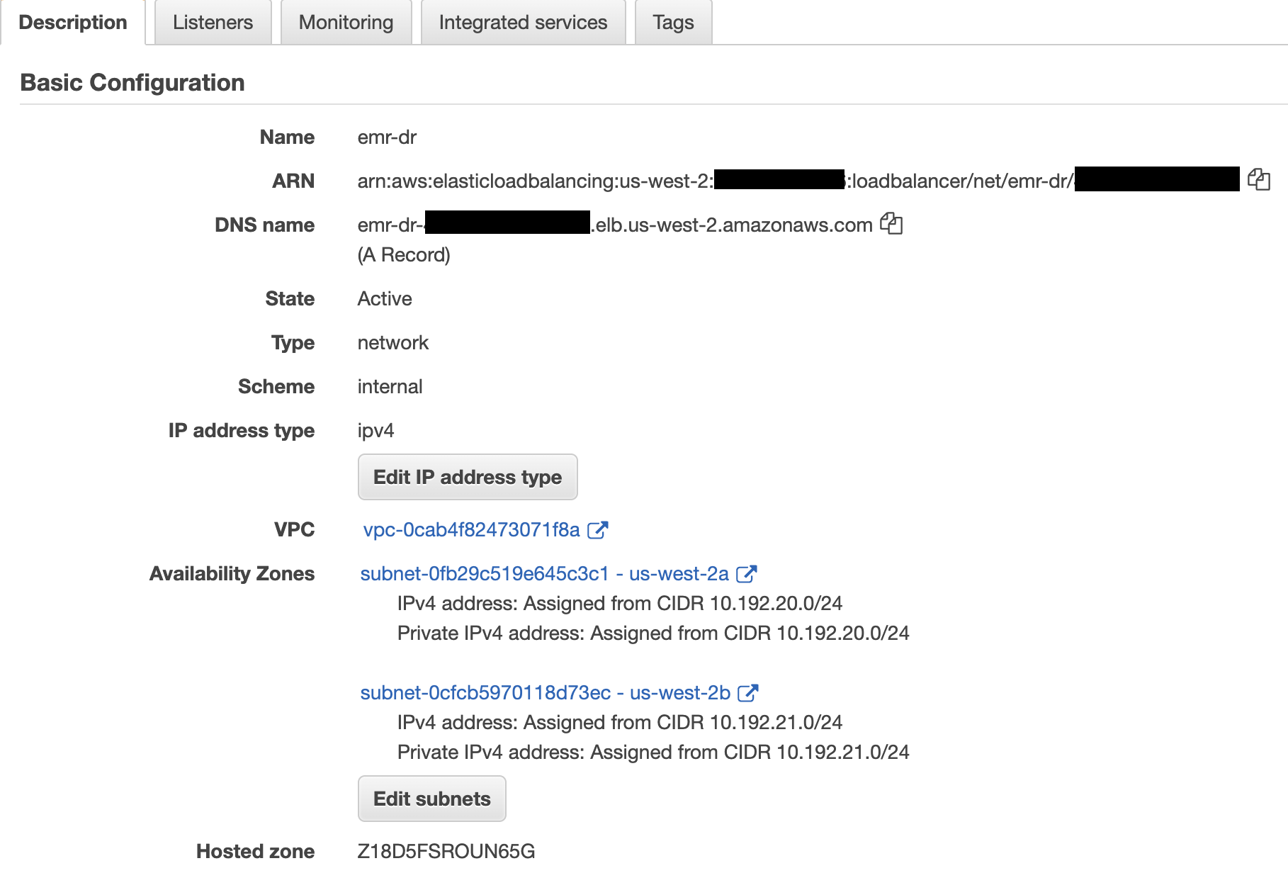
  • Create an internal Network Load Balancer in the same VPC or Region as your EMR clusters, and choose two different Availability Zones and select the private subnets.
    These subnets don’t need to be in the same subnets as the EMR clusters, but the clusters must allow the traffic from the Network Load Balancer, which is discussed in next steps.

  • Create a TCP listener on port 8998 (the default EMR cluster Livy port) to forward requests to the target group you created.
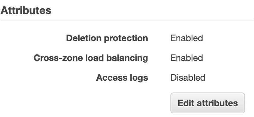
  • Modify the EMR clusters’ master security groups to allow the Network Load Balancer’s private IP addresses to access port 8998.

You can find the Network Load Balancer’s private IP address by searching the elastic network interfaces for the Network Load Balancer’s name. For access control instructions, refer to How do I attach a security group to my Elastic Load Balancer.

When the target groups become healthy, the Network Load Balancer forwards requests to registered targets when it receives requests on Livy port 8998.

  • Get the DNS name of the Network Load Balancer.

We can also use an Amazon Route 53 alias record to use our own domain name to route traffic to the Network Load Balancer DNS name. We use this DNS name in our Amazon MWAA Livy connection.

Create and configure Amazon MWAA

Complete the following steps:

  • Make sure the execution role you’re using with Amazon MWAA has proper access to EMR clusters and other required services.
  • Update the Amazon MWAA Livy connection (livy_default) host with the Network Load Balancer hostname you created.
  • Create a new Livy connection ID if it’s not already available.

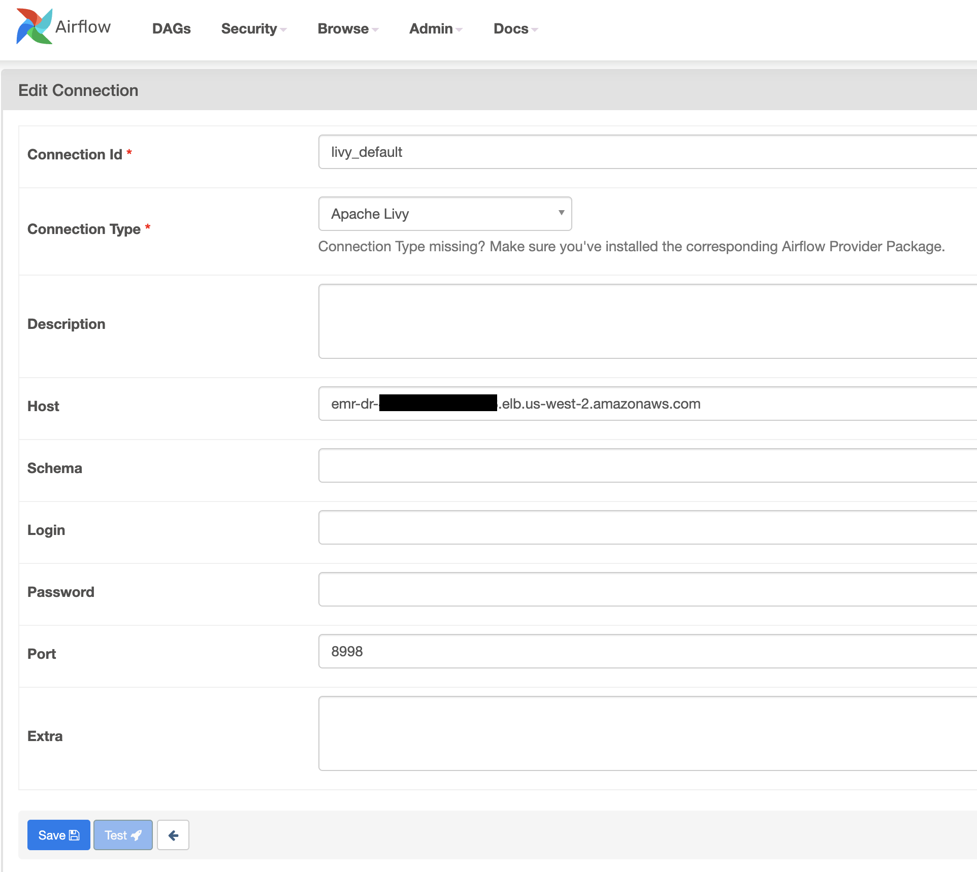
  • Use the following sample DAG to submit a sample Spark application using LivyOperator. We assign the livy_default connection to the livy_conn_id in the DAG code.
  • Enable the DAG and verify if the Spark application is successful on one of the EMR clusters.
from datetime import timedelta, datetime
from airflow.utils.dates import days_ago
from airflow import DAG
from airflow.providers.apache.livy.operators.livy import LivyOperator

default_args = {
    'owner': 'airflow',
    "retries": 1,
    "retry_delay": timedelta(minutes=5),
}

dag_name = "livy_spark_dag"
# Replace S3 bucket name
# You can use sample spark jar from EMR cluster master node
# /usr/lib/spark/examples/jars/spark-examples.jar
s3_bucket = "artifacts-bucket"
jar_location = "s3://{}/spark-examples.jar".format(s3_bucket)

dag = DAG(
    dag_id = dag_name,
    default_args=default_args,
    schedule_interval='@once',
    start_date = days_ago(1),
    catchup=False,
    tags=['emr', 'spark', 'livy']
)

livy_spark = LivyOperator(
    file=jar_location,
    class_name="org.apache.spark.examples.SparkPi",
    driver_memory="1g",
    driver_cores=1,
    executor_memory="1g",
    executor_cores=2,
    num_executors=1,
    task_id="livy_spark",
    conf={
    "spark.submit.deployMode": "cluster",
    "spark.app.name": dag_name
    },
    livy_conn_id="livy_default",
    dag=dag,
)

livy_spark

Test the DR plan

We can test our DR plan by creating scenarios that could be caused by real disasters. Perform the following steps to validate if our DR strategy works automatically during a disaster:

  1. Run the sample DAG multiple times and verify if Spark applications are randomly submitted to the registered EMR clusters.
  2. Stop one of the clusters and verify if jobs are automatically submitted to the other cluster in a different Availability Zone without any issues.

Active-passive DR strategy

Although the active-active DR strategy has benefits of maintaining near-zero recovery time, it’s complex to maintain two environments because both environments require patching and constant monitoring. In cases where Recovery Time Objective (RTO) and Recovery Point Objective (RPO) aren’t critical for your workloads, we can adopt an active-passive strategy. This approach offers a more economical and operationally less complex approach.

In this approach, we use a single EMR cluster as an active cluster and in case of disaster (due to Availability Zone failures or any other reason the EMR cluster is unhealthy), we launch a second EMR cluster in a different Availability Zone and redirect all our workloads to the newly launched cluster. End-users may notice some delay because launching a second EMR cluster takes time.

The high-level architecture of the active-passive DR solution is shown in the following diagram.

Complete the following steps to implement this solution:

  • Create an EMR cluster in a single Availability Zone.
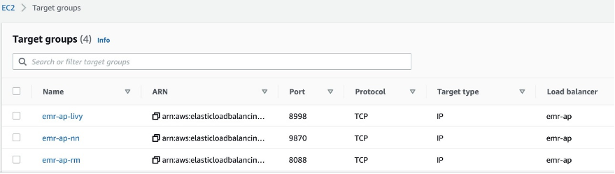
  • Create target groups and register the EMR cluster master node IP address. Create target group for Resource Manager(8088), Name Node(9870) and Livy(8998) services. Change the port numbers if services are running on different ports.

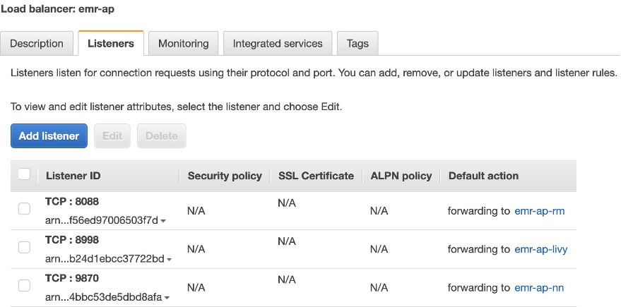
  • Create a Network Load Balancer and add TCP listeners and forward requests to the respective target groups.

  • Create an Amazon MWAA environment with proper access to the EMR cluster in the same Region.
  • Edit the Amazon MWAA Livy connection to use the Network Load Balancer DNS name.
  • Use the updated Livy connection in Amazon MWAA DAGs to submit Spark applications.
  • Validate if we can successfully submit Spark applications via Livy to the EMR cluster.
  • Set up a DAG on Amazon MWAA or similar scheduling tool that continuously monitors the existing EMR cluster health.
  • Monitor the following key services running on the Amazon EMR master host using REST APIs or commands provided by each service. Add more health checks as required.
  • If the health check process detects a failure of the first EMR cluster, create a new EMR cluster in a different Availability Zone.
  • Automatically register the newly created EMR cluster master IP address to the Network Load Balancer target groups.
  • When the Network Load Balancer health checks are successful with the new EMR cluster master IP, delete the unhealthy EMR cluster master IP address from the target group and stop the old EMR cluster.
  • Validate the DR plan.

Follow the steps mentioned in the active-active DR strategy to create the following resources:

  • Amazon EMR
  • Amazon MWAA
  • Network Load Balancer

The following sample script provides the functionality described in this section. Use this as reference and modify it accordingly to fit your use case.

#!/bin/bash

usage() {
	cat <<EOF
   Usage: ./dr_health_check.sh j-2NPQWXK1U4E6G

   This script takes current EMR cluster id as argument and monitors the cluster health and
   creates new EMR cluster in different AZ if existing cluster is unhealthy/unreachable

EOF
	exit 1
}

[[ $# -lt 1 ]] && {
	echo Specify cluster id as argument to the script
	usage
}

#Set NLB DNS name and region
hostname="emr-ap-ae4ffe5g23fd9245.elb.us-west-2.amazonaws.com"
region="us-west-2"
cluster_id=$1
cluster_status=""

export AWS_DEFAULT_REGION=$region

#Depending on the use case perform below health checks for more than one time in a loop and if cluster state is still unhealthy then only perform remaining steps
#Ports and SSL properties for curl command may differ depending on how services are set up
rm_state=$(curl -s --connect-timeout 5 --max-time 10 http://$hostname:8088/ws/v1/cluster | jq -r .clusterInfo.state)
if [[ $? -ne 0 || "$rm_state" != "STARTED" ]]; then
	echo "ResourceManager port not reachable or service not running"
	cluster_status="unhealthy"
fi

nn_state=$(curl -s --connect-timeout 5 --max-time 10 http://$hostname:9870/jmx?qry=Hadoop:service=NameNode,name=NameNodeStatus | jq -r .beans[0].State)
if [[ $? -ne 0 || "$nn_state" != "active" ]]; then
	echo "NameNode port not reachable or service not running"
	cluster_status="unhealthy"
fi

livy_state=$(curl -s --connect-timeout 5 --max-time 10 http://$hostname:8998/sessions)
if [[ $? -ne 0 ]]; then
	echo "Livy port not reachable"
	cluster_status="unhealthy"
fi

cluster_name=$(aws emr describe-cluster --cluster-id $cluster_id | jq -r ".Cluster.Name")

update_target_groups() {
	new_master_ip=$1
	current_master_ip=$2
	current_az=$3

	nlb_arn=$(aws elbv2 describe-load-balancers --query "LoadBalancers[?DNSName==\`$hostname\`].[LoadBalancerArn]" --output text)
	target_groups=$(aws elbv2 describe-target-groups --load-balancer-arn $nlb_arn --query "TargetGroups[*].TargetGroupArn" --output text)
	IFS=" " read -a tg_array <<<$target_groups
	for tg in "${tg_array[@]}"; do
		echo "Registering new EMR master IP with target group $tg"
		aws elbv2 register-targets --target-group-arn $tg --targets Id=$new_master_ip,AvailabilityZone=all

		echo "De-registering old/unhealthy EMR master IP from target group $tg"
		aws elbv2 deregister-targets --target-group-arn $tg --targets Id=$current_master_ip,AvailabilityZone=all
	done
}

if [[ $cluster_status == "unhealthy" ]]; then
	echo "Cluster status is $cluster_status, creating new EMR cluster"
	current_az=$(aws emr describe-cluster --cluster-id $cluster_id | jq -r ".Cluster.Ec2InstanceAttributes.Ec2AvailabilityZone")
	new_az=$(aws ec2 describe-availability-zones --output json --filters "Name=region-name,Values=$region" --query "AvailabilityZones[?ZoneName!=\`$current_az\`].ZoneName|[0]" --output=text)
	current_master_ip=$(aws emr list-instances --cluster-id $cluster_id --instance-group-types MASTER --query "Instances[*].PrivateIpAddress" --output text)
	echo "Current/unhealthy cluster id $cluster_id, cluster name $cluster_name,AZ $current_az, Master private ip $current_master_ip"

	echo "Creating new EMR cluster in $new_az"
	emr_op=$(aws emr create-cluster \
		--name "$cluster_name-$new_az" \
		--release-label emr-6.4.0 \
		--applications Name=Spark Name=Livy \
		--ec2-attributes "AvailabilityZone=$new_az" \
		--instance-groups InstanceGroupType=MASTER,InstanceCount=1,InstanceType=m4.large InstanceGroupType=CORE,InstanceCount=1,InstanceType=m4.large \
		--use-default-role \
		--region $region)

	new_cluster_id=$(echo $emr_op | jq -r ".ClusterId")

	#wait for cluster provisioning to get master ip address
	sleep 2m

	new_master_ip=$(aws emr list-instances --cluster-id $new_cluster_id --instance-group-types MASTER --query "Instances[*].PrivateIpAddress" --output text)
	echo "New EMR cluster id $new_cluster_id and Master node IP $new_master_ip"

	echo "Terminating unhealthy cluster $cluster_id/$cluster_name in $current_az"
	aws emr modify-cluster-attributes --cluster-id $cluster_id --no-termination-protected
	aws emr terminate-clusters --cluster-ids $cluster_id

	echo "Register new EMR master IP address with NLB target groups and de-register unhealthy EMR master"
	update_target_groups $new_master_ip $current_master_ip $current_az
else
	echo "Current cluster $cluster_id/$cluster_name is healthy"
fi

Summary

In this post, we shared some solutions and considerations to improve DR implementation using Amazon EMR on Amazon EC2, Network Load Balancer, and Amazon MWAA. Based on your use case, you can determine the type of DR strategy you want to deploy. We have provided the steps required to create the necessary environments and set up a successful DR strategy.

For more details about the systems and processes described in this post, refer to the following:


About the Author

Bharat Gamini is a Data Architect focused on Big Data & Analytics at Amazon Web Services. He helps customers architect and build highly scalable, robust and secure cloud-based analytical solutions on AWS.

Access Apache Livy using a Network Load Balancer on a Kerberos-enabled Amazon EMR cluster

Post Syndicated from Bharat Gamini original https://aws.amazon.com/blogs/big-data/access-apache-livy-using-a-network-load-balancer-on-a-kerberos-enabled-amazon-emr-cluster/

Amazon EMR is a cloud big data platform for running large-scale distributed data processing jobs, interactive SQL queries, and machine learning (ML) applications using open-source analytics frameworks such as Apache Spark, Apache Hive, and Presto. Amazon EMR supports Kerberos for authentication; you can enable Kerberos on Amazon EMR and put the cluster in a private subnet to maximize security.

To access the cluster, the best practice is to use a Network Load Balancer (NLB) to expose only specific ports, which are access-controlled via security groups. By default, the NLB prevents Kerberos ticket authentication to any Amazon EMR service.

Apache Livy is a service that enables easy interaction with a Spark cluster over a REST interface. It enables easy submission of Spark jobs or snippets of Spark code, synchronous or asynchronous result retrieval, as well as SparkContext management, all via a simple REST interface or an RPC client library.

In this post, we discuss how to provide Kerberos ticket access to Livy for external systems like Airflow and Notebooks using an NLB. You can apply this process to other Amazon EMR services beyond Livy, such as Trino and Hive.

Solution overview

The following are the high-level steps required:

  1. Create an EMR cluster with Kerberos security configuration.
  2. Create an NLB with required listeners and target groups.
  3. Update the Kerberos Key Distribution Center (KDC) to create a new service principal and keytab changes.
  4. Update the Livy configuration file.
  5. Verify Livy is accessible via the NLB.
  6. Run the Python Livy test case.

Prerequisites

The advanced configuration presented in this post assumes familiarity with Amazon EMR, Kerberos, Livy, Python and bash.

Create an EMR cluster

Create the Kerberos security configuration using the AWS Command Line Interface (AWS CLI) as follows (this creates the KDC on the EMR primary node):

aws emr create-security-configuration --name kdc-security-config --security-configuration '{
   "EncryptionConfiguration":{
      "InTransitEncryptionConfiguration":{
         "TLSCertificateConfiguration":{
            "CertificateProviderType":"PEM",
            "S3Object":"s3://${conf_bucket}/${certs.zip}"
         }
      },
      "AtRestEncryptionConfiguration":{
         "S3EncryptionConfiguration":{
            "EncryptionMode":"SSE-S3"
         }
      },
      "EnableInTransitEncryption":true,
      "EnableAtRestEncryption":true
   },
   "AuthenticationConfiguration":{
      "KerberosConfiguration":{
         "Provider":"ClusterDedicatedKdc",
         "ClusterDedicatedKdcConfiguration":{
            "TicketLifetimeInHours":24
         }
      }
   }
}'

It’s a security best practice to keep passwords in AWS Secrets Manager. You can use a bash function like the following as the argument to the --kerberos-attributes option so no passwords are stored in the launch script or command line. The function outputs the required JSON for the --kerberos-attributes option after retrieving the password from Secrets Manager.

krbattrs() { # Pull the KDC password from Secrets Manager without saving to disk or var
cat << EOF
  {
    "Realm": "EC2.INTERNAL",
    "KdcAdminPassword": "$(aws secretsmanager get-secret-value \
        --secret-id KDCpasswd  |jq -r .SecretString)"
  }
EOF
}

Create the cluster using the AWS CLI as follows:

aws emr create-cluster \
  --name "<your-cluster-name>" \
  --release-label emr-6.4.0 \
  --log-uri "s3://<your-log-bucket>" \
  --applications Name=Hive Name=Spark \
  --ec2-attributes "KeyName=<your-key-name>,SubnetId=<your-private-subnet>" \
  --instance-groups InstanceGroupType=MASTER,InstanceCount=1,InstanceType=m3.xlarge InstanceGroupType=CORE,InstanceCount=1,InstanceType=m3.xlarge \
  --security-configuration <kdc-security-config> \
  --kerberos-attributes $(krbattrs) \
  --use-default-roles

Create an NLB

Create an internet-facing NLB with TCP listeners in your VPC and subnet. An Internet-facing load balancer routes requests from clients to targets over the internet.  Conversely, an Internal NLB routes requests to targets using private IP addresses. For instructions, refer to Create a Network Load Balancer.

The following screenshot shows the listener details.

Create target groups and register the EMR primary instance (Livy3) and KDC instance (KDC3). For this post, these instances are the same; use the respective instances if KDC is running on a different instance.

The KDC and EMR security groups must allow the NLB’s private IP address to access ports 88 and 8998, respectively. You can find the NLB’s private IP address by searching the elastic network interfaces for the NLB’s name. For access control instructions, refer to this article on the knowledge center. Now that the security groups allow access, the NLB health check should pass, but Livy isn’t usable via the NLB until you make further changes (detailed in the following sections). The NLB is actually being used as a proxy to access Livy rather than doing any load balancing.

Update the Kerberos KDC

The KDC used by the Livy service must contain a new HTTP Service Principal Name (SPN) using the public NLB host name.

  • You can create the new principle from the EMR primary host using the full NLB public host name:
sudo kadmin.local addprinc HTTP/[email protected]

Replace the fully qualified domain name (FQDN) and Kerberos realm as needed. Ensure the NLB hostname is all lowercase.

After the new SPN exists, you create two keytabs containing that SPN. The first keytab is for the Livy service. The second keytab, which must use the same KVNO number as the first keytab, is for the Livy client.

  • Create Livy service keytab as follows:
sudo kadmin.local ktadd -norandkey -k /etc/livy2.keytab livy/[email protected]
sudo kadmin.local ktadd -norandkey -k /etc/livy2.keytab HTTP/[email protected]
sudo chown livy:livy /etc/livy2.keytab
sudo chmod 600 /etc/livy2.keytab
sudo -u livy klist -e -kt /etc/livy2.keytab

Note the key version number (KVNO) for the HTTP principal in the output of the preceding klist command. The KVNO numbers for the HTTP principal must match the KVNO numbers in the user keytab. Copy the livy2.keytab file to the EMR cluster Livy host if it’s not already there.

  • Create a user or client keytab as follows:
sudo kadmin.local ktadd -norandkey -k /var/tmp/user1.keytab [email protected]
sudo kadmin.local ktadd -norandkey -k /var/tmp/user1.keytab HTTP/[email protected]

Note the -norandkey option used when adding the SPN. That preserves the KVNO created in the preceding livy2.keytab.

  • Copy the user1.keytab to the client machine running the Python test case as user1.

Replace the FQDN, realm, and keytab path as needed.

Update the Livy configuration file

The primary change on the EMR cluster primary node running the Livy service is to the /etc/livy/conf/livy.conf file. You change the authentication principal that Livy uses, as well as the associated Kerberos keytab created earlier.

  • Make the following changes to the livy.conf file with sudo:
livy.server.auth.kerberos.principal = HTTP/[email protected]
livy.server.auth.kerberos.keytab = /etc/livy2.keytab

Don’t change the livy.server.launch.kerberos.* values.

  • Restart and verify the Livy service:
sudo systemctl restart livy-server
sudo systemctl status livy-server
  • Verify the Livy port is listening:
sudo lsof -Pi :8998

COMMAND PID USER FD TYPE DEVICE SIZE/OFF NODE NAME
java 30106 livy 196u IPv6 224853844 0t0 TCP *:8998 (LISTEN)

You can automate these steps (modifying the KDC and Livy config file) by adding a step to the EMR cluster. For more information, refer to Tutorial: Configure a cluster-dedicated KDC.

Verify Livy is accessible via the NLB

You can now use user1.keytab to authenticate against the Livy REST endpoint. Copy the user1.keytab you created earlier to the host and user login, which run the Livy test case. The host running the test case must be configured to connect to the modified KDC.

  • Create a Linux user (user1) on client host and EMR cluster.

If the client host has a terminal available that the user can run commands in, you can use the following commands to verify network connectivity to Livy before running the actual Livy Python test case.

  • Verify the NLB host and port are reachable (no data will be returned by the nc command):
$ nc -vz mynlb-a0ac4b07f9f7f0a1.elb.us-west-2.amazonaws.com 8998
Ncat: Version 7.50 ( https://nmap.org/ncat )
Ncat: Connected to 44.242.1.1:8998.
Ncat: 0 bytes sent, 0 bytes received in 0.02 seconds.
  • Create a TLS connection, which returns the server’s TLS certificate and TCP packets:
openssl s_client -connect mynlb-a0ac4b07f9f7f0a1.elb.us-west-2.amazonaws.com:8998

If the openssl command doesn’t return a TLS server certificate, the rest of the verification doesn’t succeed. You may have a proxy or firewall interfering with the connection. Investigate your network environment, resolve the issue, and repeat the openssl command to ensure connectivity.

  • Verify the Livy REST endpoint using curl. This verifies Livy REST but not Spark.
kinit -kt user1.keytab [email protected]
curl -k -u : --negotiate https://mynlb-a0ac4b07f9f7f0a1.elb.us-west-2.amazonaws.com:8998/sessions
{"from":0,"total":0,"sessions":[]}

curl arguments:
  "-k"   - Ignore secure connection check
  "-u :" - Use user name and passwords from environment
  "--negotiate" – Enables negotiate(SPNEGO) authentication

Run the Python Livy test case

The Livy test case is a simple Python3 script named livy-verify.py. You can run this script from a client machine to run Spark commands via Livy using the NLB. The script is as follows:

#!/usr/bin/env python3
# pylint: disable=invalid-name,no-member

"""
Verify Livy (REST) service using pylivy module, install req modules or use PEX:
  sudo yum install python3-devel
  sudo python3 -m pip install livy==0.8.0 requests==2.27.1 requests_gssapi==1.2.3
  https://pypi.org/project/requests-gssapi/

Kerberos authN implicitly uses TGT from kinit in users login env
"""

import shutil
import requests
from requests_gssapi import HTTPSPNEGOAuth
from livy import LivySession

# Disable ssl-warnings for self-signed certs when testing
requests.packages.urllib3.disable_warnings()

# Set the base URI(use FQDN and TLS) to target a Livy service
# Redefine remote_host to specify the remote Livy hostname to connect to
remote_host="mynlb-a0ac4b07f9f7f0a1.elb.us-west-2.amazonaws.com"
livy_uri = "https://" + remote_host + ":8998"

def livy_session():
    ''' Connect to Livy (REST) and run trivial pyspark command '''
    sconf = {"spark.master": "yarn", "spark.submit.deployMode": "cluster"}

    if shutil.which('kinit'):
        kauth = HTTPSPNEGOAuth()
        # Over-ride with an explicit user principal
        #kauth = HTTPSPNEGOAuth(principal="[email protected]")
        print("kinit found, kauth using Krb cache")
    else:
        kauth = None
        print("kinit NOT found, kauth set to None")

    with LivySession.create(livy_uri, verify=False, auth=kauth, spark_conf=sconf) as ls:
        ls.run("rdd = sc.parallelize(range(100), 2)")
        ls.run("rdd.take(3)")

    return 'LivySession complete'

def main():
    """ Starting point """
    livy_session()

if __name__ == '__main__':
    main()

The test case requires the new SPN to be in the user’s Kerberos ticket cache. To get the service principal into the Kerberos cache, use the kinit command with the -S option:

kinit -kt user1.keytab -S HTTP/[email protected] [email protected]

Note the SPN and the User Principal Name (UPN) are both used in the kinit command.

The Kerberos cache should look like the following code, as revealed by the klist command:

klist
Ticket cache: FILE:/tmp/krb5cc_1001
Default principal: [email protected]

Valid starting Expires Service principal
01/20/2022 01:38:06 01/20/2022 11:38:06 HTTP/[email protected]
renew until 01/21/2022 01:38:06

Note the HTTP service principal in the klist ticket cache output.

After the SPN is in the cache as verified by klist, you can run the following command to verify that Livy accepts the Kerberos ticket and runs the simple PySpark script. It generates a simple array, [0,1,2], as the output. The preceding Python script has been copied to the /var/tmp/user1/ folder in this example.

/var/tmp/user1/livy-verify.py
kinit found, kauth using TGT
[0, 1, 2]

It can take a minute or so to generate the result. Any authentication errors will happen in seconds. If the test in the new environment generates the preceding array, the Livy Kerberos configuration has been verified.

Any other client program that needs to have Livy access must be a Kerberos client of the KDC that generated the keytabs. It must also have a client keytab (such as user1.keytab or equivalent) and the service principal key in its Kerberos ticket cache.

In some environments, a simple kinit as follows may be sufficient:

kdestroy
kinit -kt user1.keytab [email protected]

Summary

If you have an existing EMR cluster running Livy and using Kerberos (even in a private subnet), you can add an NLB to connect to the Livy service and still authenticate with Kerberos. For simplicity, we used a cluster-dedicated KDC in this post, but you can use any KDC architecture option supported by Amazon EMR. This post documented all the KDC and Livy changes to make it work; the script and procedure have been run successfully in multiple environments. You can modify the Python script as needed and try running the verification script in your environment.

For more details about the systems and processes described in this post, refer to the following:


About the Authors

John Benninghoff is a AWS Professional Services Sr. Data Architect, focused on Data Lake architecture and implementation.

Bharat Gamini is a Data Architect focused on Big Data & Analytics at Amazon Web Services. He helps customers architect and build highly scalable, robust and secure cloud-based analytical solutions on AWS. Besides family time, he likes watching movies and sports.