All posts by Lorenzo Ripani

Enhance Amazon EMR scaling capabilities with Application Master Placement

Post Syndicated from Lorenzo Ripani original https://aws.amazon.com/blogs/big-data/enhance-amazon-emr-scaling-capabilities-with-application-master-placement/

In today’s data-driven world, processing large datasets efficiently is crucial for businesses to gain insights and maintain a competitive edge. Amazon EMR is a managed big data service designed to handle these large-scale data processing needs across the cloud. It allows running applications built using open source frameworks on Amazon Elastic Compute Cloud (Amazon EC2), Amazon Elastic Kubernetes Service (Amazon EKS), or AWS Outposts, or completely serverless. One of the key features of Amazon EMR on EC2 is managed scaling, which dynamically adjusts computing capacity in response to application demands, providing optimal performance and cost-efficiency.

Although managed scaling aims to optimize EMR clusters for best price-performance and elasticity, some use cases require more granular resource allocation. For example, when multiple applications are submitted to the same clusters, resource contention may occur, potentially impacting both performance and cost-efficiency. Additionally, allocating the Application Master (AM) container to non-reliable nodes like Spot can potentially result in loss of the container and immediate shutdown of the entire YARN application, resulting in wasted resources and additional costs for rescheduling the entire YARN application. These uses cases require more granular resource allocation and sophisticated scheduling policies to optimize resource utilization and maintain high performance.

Starting with the Amazon EMR 7.2 release, Amazon EMR on EC2 introduced a new feature called Application Master (AM) label awareness, which allows users to enable YARN node labels to allocate the AM containers within On-Demand nodes only. Because the AM container is responsible for orchestrating the overall job execution, it’s crucial to verify that it gets allocated to a reliable instance and not be subjected to shutdown due to Spot Instance interruption. Additionally, limiting AM containers to On-Demand helps maintain consistent application launch time, because the fulfillment of the On-Demand Instance isn’t prone to unavailable Spot capacity or bid price.

In this post, we explore the key features and use cases where this new functionality can provide significant benefits, enabling cluster administrators to achieve optimal resource utilization, improved application reliability, and cost-efficiency in your EMR on EC2 clusters.

Solution overview

The Application Master label awareness feature in Amazon EMR works in conjunction with YARN node labels, a functionality offered by Hadoop that empowers you to define labels to nodes within a Hadoop cluster. You can use these labels to determine which nodes of the cluster should host specific YARN containers (such as mappers vs. reducers in a MapReduce, or drivers vs. executors in Apache Spark).

This feature is enabled by default when a cluster is launched with Amazon EMR 7.2.0 and later using Amazon EMR managed scaling, and it has been configured to use YARN node labels. The following code is a basic configuration setup that enables this feature:

[
   {
     "Classification": "yarn-site",
     "Properties": {
      "yarn.node-labels.enabled": "true",
       "yarn.node-labels.am.default-node-label-expression": "ON_DEMAND"
     }
   }
]

Within this configuration snippet, we activate the Hadoop node label feature and define a value for the yarn.node-labels.am.default-node-label-expression property. This property defines the YARN node label that will be used to schedule the AM container of each YARN application submitted to the cluster. This specific container plays a key role in maintaining the lifecycle of the workflow, so verifying its placement on reliable nodes in production workloads is crucial, because the unexpected shutdown of this container can result in the shutdown and failure of the entire application.

Currently, the Application Master label awareness feature only supports two predefined node labels that can be specified to allocate the AM container of a YARN job: ON_DEMAND and CORE. When one of these labels is defined using Amazon EMR configurations (see the preceding example code), Amazon EMR automatically creates the corresponding node labels in YARN and labels the instances in the cluster accordingly.

To demonstrate how this feature works, we launch a sample cluster and run some Spark jobs to see how Amazon EMR managed scaling integrates with YARN node labels.

Launch an EMR cluster with Application Manager placement awareness

To perform some tests, you can launch the following AWS CloudFormation stack, which provisions an EMR cluster with managed scaling and the Application Manager placement awareness feature enabled. If this is your first time launching an EMR cluster, make sure to create the Amazon EMR default roles using the following AWS Command Line Interface (AWS CLI) command:

aws emr create-default-roles

To create the cluster, choose Launch Stack:

Launch Cloudformation Stack

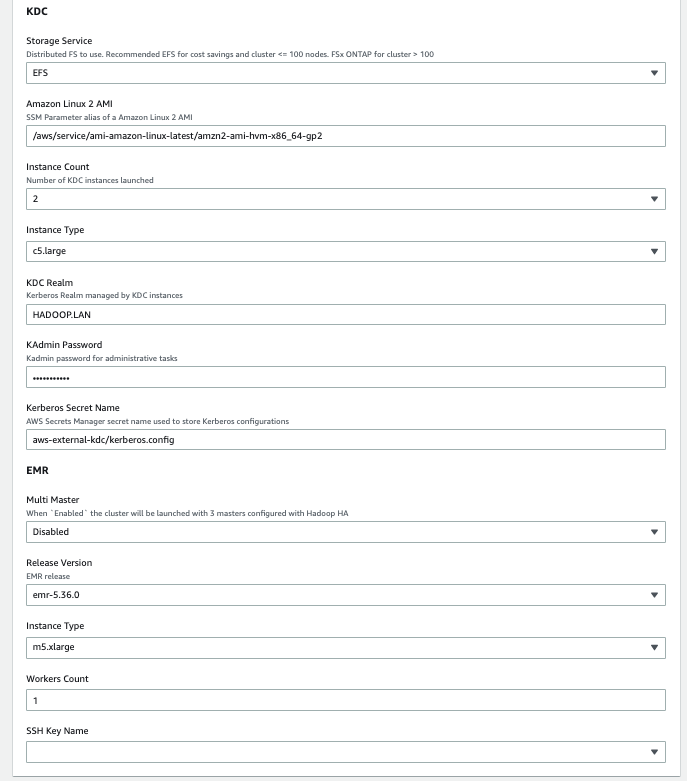
Provide the following required parameters:

  • VPC – An existing virtual private cloud (VPC) in your account where the cluster will be provisioned
  • Subnet – The subnet in your VPC where you want to launch the cluster
  • SSH Key Name – An EC2 key pair that you use to connect to the EMR primary node

After the EMR cluster has been provisioned, establish a tunnel to the Hadoop Resource Manager web UI to review the cluster configurations. To access the Resource Manager web UI, complete the following steps:

  1. Set up an SSH tunnel to the primary node using dynamic port forwarding.
  2. Point your browser to the URL http://<primary-node-public-dns>:8088/, using the public DNS name of your cluster’s primary node.

This will open the Hadoop Resource Manager web UI, where you can see how the cluster has been configured.

YARN node labels

In the CloudFormation stack, you launched a cluster specifying to allocate the AM containers on nodes labeled as ON_DEMAND. If you explore the Resource Manager web UI, you can see that Amazon EMR created two labels in the cluster: ON_DEMAND and SPOT. To review the YARN node labels present in your cluster, you can inspect the Node Labels page, as shown in the following screenshot.

On this page, you can see how the YARN labels were created in Amazon EMR:

  • During initial cluster creation, default node labels such as ON_DEMAND and SPOT are automatically generated as non-exclusive partitions
  • The DEFAULT_PARTITION label stays vacant because every node gets labeled based on its market type—either being an On-Demand or Spot Instance

In our example, because we launched a single core node as On-Demand, you can observe a single node assigned to the ON_DEMAND partition, and the SPOT partition remains empty. Because the labels are created as non-exclusive, nodes with these labels can run both containers launched with a specific YARN label and also containers that don’t specify a YARN label. For additional details on YARN node labels, see YARN Node Labels in the Hadoop documentation.

Now that we have discussed how the cluster was configured, we can perform some tests to validate and review the behavior of this feature when using it in combination with managed scaling.

Concurrent application submission with Spot Instances

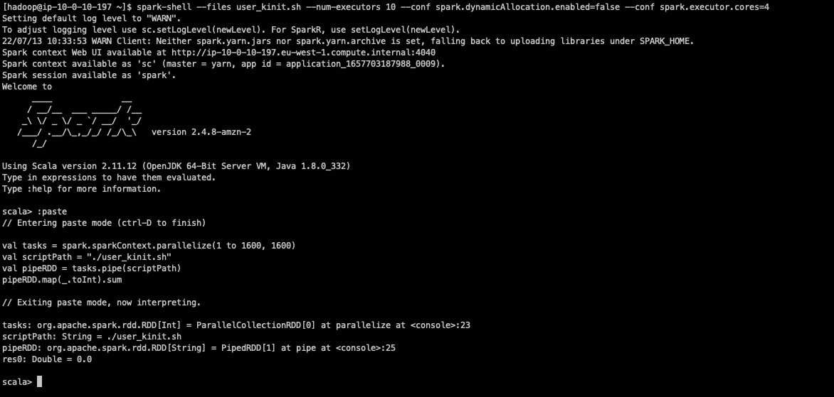
To test the managed scaling capabilities, we submit a simple SparkPi job configured to utilize all available memory on the single core node initially launched in our cluster:

spark-example \
  --deploy-mode cluster \
  --driver-memory 10g \
  --executor-memory 10g \
  --conf spark.dynamicAllocation.maxExecutors=1 \
  --conf spark.yarn.executor.nodeLabelExpression=SPOT \
  SparkPi 800000

In the preceding snippet, we tuned specific Spark configurations to utilize all the resources of the cluster nodes launched (you could also achieve this using the maximizeResourceAllocation configuration while launching an EMR cluster). Because the cluster has been launched using m5.xlarge instances, we can launch individual containers up to 12 GB in terms of memory requirements. With these assumptions, the snippet configures the following:

  • The Spark driver and executors were configured with 10 GB of memory to utilize most of the available memory on the node, in order to have a single container running on each node of our cluster and simplify this example.
  • The node-labels.am.default-node-label-expression parameter was set to ON_DEMAND, making sure the Spark driver is automatically allocated to the ON_DEMAND partition of our cluster. Because we specified this configuration while launching the cluster, the AM containers are automatically requested to be scheduled on ON_DEMAND labeled instances, so we don’t need to specify it at the job level.
  • The yarn.executor.nodeLabelExpression=SPOT configuration verifies that the executors operated exclusively on TASK nodes using Spot Instances. Removing this configuration allows the Spark executors to be scheduled both on SPOT and ON_DEMAND labeled nodes.
  • The dynamicAllocation.maxExecutors setting was set to 1 to delay the processing time of the application and observe the scaling behavior when multiple YARN applications were submitted concurrently in the same cluster.

As the application transitioned to a RUNNING state, we can verify from the YARN Resource Manager UI that its driver placement was automatically assigned to the ON_DEMAND partition of our cluster (see the following screenshot).

Additionally, upon inspecting the YARN scheduler page, we can see that our SPOT partition doesn’t have a resource associated with it because the cluster was launched with just one On-Demand Instance.

Because the cluster didn’t have Spot Instances initially, you can observe from the Amazon EMR console that managed scaling generates a new Spot task group to accommodate the Spark executor requested to run on Spot nodes only (see the following screenshot) . Before this integration, managed scaling didn’t take into account the YARN labels requested by an application, potentially leading to unpredictable scaling behaviors. With this release, managed scaling now considers the YARN labels specified by applications, enabling more predictable and accurate scaling decisions.

While waiting for the launch of the new Spot node, we submitted another SparkPi job with identical specifications. However, because the memory required to allocate the new Spark Driver was 10 GB and such resources were currently unavailable in the ON_DEMAND partition, the application remained in a pending state until resources became available to schedule its container.

Upon detecting the lack of resources to allocate the new Spark driver, Amazon EMR managed scaling commenced scaling the core instance group (On-Demand Instances in our cluster) by launching a new core node. After the new core node was launched, YARN promptly allocated the pending container on the new node, enabling the application to start its processing. Subsequently, the application requested additional Spot nodes to allocate its own executors (see the following screenshot).

This example demonstrates how managed scaling and YARN labels work together to improve the resiliency of YARN applications, while using cost-effective job executions over Spot Instances.

When to use Application Manager placement awareness and managed scaling

You can use this placement awareness feature to improve cost-efficiency by using Spot Instances while protecting the Application Manager from being incorrectly shut down due to Spot interruptions. It’s particularly useful when you want to take advantage of the cost savings offered by Spot Instances while preserving the stability and reliability of your jobs running on the cluster. When working with managed scaling and the placement awareness feature, consider the following best practices:

  • Maximum cost-efficiency for non-critical jobs – If you have jobs that don’t have strict service level agreement (SLA) requirements, you can force all Spark executors to run on Spot Instances for maximum cost savings. This can be achieved by setting the following Spark configuration:
    spark.yarn.executor.nodeLabelExpression=SPOT

  • Resilient execution for production jobs – For production jobs where you require a more resilient execution, you might consider not setting the yarn.executor.nodeLabelExpression parameter. When no label is specified, executors are dynamically allocated between both On-Demand and Spot nodes, providing a more reliable execution.
  • Limit dynamic allocation for concurrent applications – When working with managed scaling and clusters with multiple applications running concurrently (for example, an interactive cluster with concurrent user utilization), you should consider setting a maximum limit for Spark dynamic allocation using the dynamicAllocation.maxExecutors setting. This can help manage resources over-provisioning and facilitate predictable scaling behavior across applications running on the same cluster. For more details, see Dynamic Allocation in the Spark documentation.
  • Managed scaling configurations – Make sure your managed scaling configurations are set up correctly to facilitate efficient scaling of Spot Instances based on your workload requirements. For example, set an appropriate value for Maximum On-Demand instances in managed scaling based on the number of concurrent applications you want to run on the cluster. Additionally, if you’re planning to use your On-Demand Instances for running solely AM containers, we recommend setting scheduler.capacity.maximum-am-resource-percent to 1 using the Amazon EMR capacity-scheduler classification.
  • Improve startup time of the nodes – If your cluster is subject to frequent scaling events (for example, you have a long-running cluster that can run multiple concurrent EMR steps), you might want to optimize the startup time of your cluster nodes. When trying to get an efficient node startup, consider only installing the minimum required set of application frameworks in the cluster and, whenever possible, avoid installing non-YARN frameworks such as HBase or Trino, which might delay the startup of processing nodes dynamically attached by Amazon EMR managed scaling. Finally, whenever possible, don’t use complex and time-consuming EMR bootstrap actions to avoid increasing the startup time of nodes launched with managed scaling.

By following these best practices, you can take advantage of the cost savings of Spot Instances while maintaining the stability and reliability of your applications, particularly in scenarios where multiple applications are running concurrently on the same cluster.

Conclusion

In this post, we explored the benefits of the new integration between Amazon EMR managed scaling and YARN node labels, reviewed its implementation and usage, and defined a few best practices that can help you get started. Whether you’re running batch processing jobs, stream processing applications, or other YARN workloads on Amazon EMR, this feature can help you achieve substantial cost savings without compromising on performance or reliability.

As you embark on your journey to use Spot Instances in your EMR clusters, remember to follow the best practices outlined in this post, such as setting appropriate configurations for dynamic allocation, node label expressions, and managed scaling policies. By doing so, you can make sure that your applications run efficiently, reliably, and at the lowest possible cost.


About the authors

Lorenzo Ripani is a Big Data Solution Architect at AWS. He is passionate about distributed systems, open source technologies and security. He spends most of his time working with customers around the world to design, evaluate and optimize scalable and secure data pipelines with Amazon EMR.

Miranda Diaz is a Software Development Engineer for EMR at AWS. Miranda works to design and develop technologies that make it easy for customers across the world to automatically scale their computing resources to their needs, helping them achieve the best performance at the optimal cost.

Sajjan Bhattarai is a Senior Cloud Support Engineer at AWS, and specializes in BigData and Machine Learning workloads. He enjoys helping customers around the world to troubleshoot and optimize their data platforms.

Bezuayehu Wate is an Associate Big Data Specialist Solutions Architect at AWS. She works with customers to provide strategic and architectural guidance on designing, building, and modernizing their cloud-based analytics solutions using AWS.

Implement a highly available key distribution center for Amazon EMR

Post Syndicated from Lorenzo Ripani original https://aws.amazon.com/blogs/big-data/implement-a-highly-available-key-distribution-center-for-amazon-emr/

High availability (HA) is the property of a system or service to operate continuously without failing for a designated period of time. Implementing HA properties over a system allows you to eliminate single points of failure that usually translate to service disruptions, which can then lead to a business loss or the inability to use a service.

The core idea behind fault tolerance and high availability is very straightforward in terms of definition. You usually use multiple machines to give you redundancy for a specific service. This guarantees that if a host goes down, other machines are able to take over the traffic. Although this might be easy to say, it’s difficult to obtain such a property, especially when working with distributed technologies.

When focusing on Hadoop technologies, the concept of availability multiplies in different layers depending on the frameworks we’re using. To achieve a fault-tolerant system, we need to consider the following layers:

  • Data layer
  • Processing layer
  • Authentication layer

The first two layers are typically handled using native capabilities of the Hadoop framework (such as HDFS High Availability or ResourceManager High Availability) or with the help of features available in the specific framework used (for example, HBase table replication to achieve highly available reads).

The authentication layer is typically managed through the utilization of the Kerberos protocol. Although multiple implementations of Kerberos exist, Amazon EMR uses a free implementation of the Kerberos protocol, which is directly provided by the Massachusetts Institute of Technology (MIT), also referred to as MIT Kerberos.

When looking at the native setup for a key distribution center (KDC), we can see that the tool comes with a typical primary/secondary configuration, where you can configure a primary KDC with one or more additional replicas to provide some features of a highly available system.

However, this configuration doesn’t provide an automatic failover mechanism to elect a new primary KDC in the event of a system interruption. As a result, the failover has to be performed manually or by implementing an automated process, which can be complex to set up.

With AWS native services, we can improve the MIT KDC capabilities to increase the resilience to failures of our system.

Highly available MIT KDC

Amazon EMR provides different architecture options to enable Kerberos authentication, where each of them tries to solve a specific need or use case. Kerberos authentication can be enabled by defining an Amazon EMR security configuration, which is a set of information stored within Amazon EMR itself. This enables you to reuse this configuration across multiple clusters.

When creating an Amazon EMR security configuration, you’re asked to choose between a cluster-dedicated KDC or an external KDC, so it’s important to understand the benefits and limits of each solution.

When you enable the cluster-dedicated KDC, Amazon EMR configures and installs an MIT KDC on the EMR primary node of the cluster that you’re launching. In contrast, when you use an external KDC, the cluster launched relies on a KDC external to the cluster. In this case, the KDC can be a cluster-dedicated KDC of a different EMR cluster that you reference as an external KDC, or a KDC installed on an Amazon Elastic Compute Cloud (Amazon EC2) instance or a container that you own.

The cluster-dedicated KDC is an easy configuration option that delegates the installation and configuration of the KDC service to the cluster itself. This option doesn’t require significant knowledge of the Kerberos system and might be a good option for a test environment. Additionally, having a dedicated KDC in a cluster enables you to segregate the Kerberos realm, thereby providing a dedicated authentication system that can be used only to authenticate a specific team or department in your organization.

However, because the KDC is located on the EMR primary node, you have to consider that if you delete the cluster, the KDC will be deleted as well. Considering the case in which the KDC is shared with other EMR clusters (defined as external KDC in their security configuration), the authentication layer for those will be compromised and as a result all Kerberos enabled frameworks will break. This might be acceptable in test environments, but it’s not recommended for a production one.

Because the KDC lifetime isn’t always bound to a specific EMR cluster, it’s common to use an external KDC located on an EC2 instance or Docker container. This pattern comes with some benefits:

  • You can persist end-user credentials in the Kerberos KDC rather than using an Active Directory (although you can also enable a cross-realm trust)
  • You can enable communication across multiple EMR clusters, so that all the cluster principals join the same Kerberos realm, thereby enabling a common authentication system for all the clusters
  • You can remove the dependency of the EMR primary node, because deleting it will result in an impairment for other systems to authenticate
  • If you require a multi-master EMR cluster, then an external KDC is required

That being said, installing an MIT KDC on a single instance doesn’t address our HA requirements, which typically are crucial in a production environment. In the following section, we discuss how we can implement a highly available MIT KDC using AWS services to improve the resiliency of our authentication system.

Architecture overview

The architecture presented in the following diagrams describes a highly available setup across multiple Availability Zones for our MIT Kerberos KDC that uses AWS services. We propose two versions of the architecture: one based on an Amazon Elastic File System (Amazon EFS) file system, and another based on an Amazon FSx for NetApp ONTAP file system.

Both services can be mounted on EC2 instances and used as local paths. Although Amazon EFS is cheaper compared to Amazon FSx for NetApp ONTAP, the latter provides better performance thanks to the sub-millisecond operation latency it provides.

We performed multiple tests to benchmark the solutions involving the different file systems. The following graph shows the results with Amazon EMR 5.36, in which we measured the time in seconds taken by the cluster to be fully up and running when selecting Hadoop and Spark as frameworks.

Looking at the test results, we can see that the Amazon EFS file system is suitable to handle small clusters (fewer than 100 nodes), because the performance degradation introduced by the latency of lock operations on the NFS protocol increases the delay in launching clusters as we add more nodes in our cluster topology. For example, for clusters with 200 nodes, the delay introduced by the Amazon EFS file system is such that some instances can’t join the cluster in time. As a result, those instances are deleted and then replaced, making the entire cluster provisioning slower. This is the reason why we decided not to publish any metric for Amazon EFS for 200 cluster nodes on the preceding graph.

On the other side, Amazon FSx for NetApp ONTAP is able to better handle the increasing number of principals created during the cluster provisioning with reduced performance degradation compared to Amazon EFS.

Even with the solution involving Amazon FSx for NetApp ONTAP, for clusters with a higher number of instances it’s still possible to encounter the behavior described earlier for Amazon EFS. Therefore, for big cluster configurations, this solution should be carefully tested and evaluated.

Amazon EFS based solution

The following diagram illustrates the architecture of our Amazon EFS based solution.

The infrastructure relies on different components to improve the fault tolerance of the KDC. The architecture uses the following services:

  • A Network Load Balancer configured to serve Kerberos service ports (port 88 for authentication and port 749 for admin tasks like principals creation and deletion). The purpose of this component is to balance requests across multiple KDC instances located in separate Availability Zones. In addition, it provides a redirection mechanism in case of failures while connecting to an impaired KDC instance.
  • An EC2 Auto Scaling group that helps you maintain KDC availability and allows you to automatically add or remove EC2 instances according to conditions you define. For the purpose of this scenario, we define a minimum number of KDC instances equal to two.
  • The Amazon EFS file system provides a persistent and reliable storage layer for our KDC database. The service comes with built-in HA properties, so we can take advantage of its native features to obtain a persistent and reliable file system.
  • We use AWS Secrets Manager to store and retrieve Kerberos configurations, in specific the password used for the Kadmin service, the Kerberos domain and realm managed by the KDC. With Secrets Manager, we avoid inputting any sensitive information as script parameters or passwords while launching KDC instances.

With this configuration, we eliminate the downsides resulting from a single instance installation:

  • The KDC isn’t a single point of failure anymore because failed connections are redirected to healthy KDC hosts
  • The lack of Kerberos traffic against the EMR primary node for the authentication will improve the health of our primary node, which might be critical for large Hadoop installations (hundreds of nodes)
  • We can recover in case of failures, allowing survived instances to fulfill both admin and authentication operations

Amazon FSx for NetApp ONTAP based solution

The following diagram illustrates the solution using Amazon FSx for NetApp ONTAP.

This infrastructure is almost identical compared to the previous one and provides the same benefits. The only difference is the utilization of a Multi-AZ Amazon FSx for NetApp ONTAP file system as a persistent and reliable storage layer for our KDC database. Even in this case, the service comes with built-in HA properties so we can take advantage of its native features to obtain a persistent and reliable file system.

Solution resources

We provide an AWS CloudFormation template in this post as a general guide. You should review and customize it as needed. You should also be aware that some of the resources deployed by this stack incur costs when they remain in use.

The CloudFormation template contains several nested templates. Together, they create the following:

  • An Amazon VPC with two public and two private subnets where the KDC instances can be deployed
  • An internet gateway attached to the public subnets and a NAT gateway for the private subnets
  • An Amazon Simple Storage Service (Amazon S3) gateway endpoint and a Secrets Manager interface endpoint in each subnet

After the VPC resources are deployed, the KDC nested template is launched and provisions the following components:

  • Two target groups, each connected to a listener for the specific KDC port to monitor (88 for Kerberos authentication and 749 for Kerberos administration).
  • One Network Load Balancer to balance requests across the KDC instances created in different Availability Zones.
  • Depending on the chosen file system, an Amazon EFS or Amazon FSx for NetApp ONTAP file system is created across multiple Availability Zones.
  • Configuration and auto scaling to provision the KDC instances. In specific, the KDC instances are configured to mount the selected file system on a local folder that is used to store the principals database of the KDC.

At the end of the second template, the EMR cluster is launched with an external KDC set up and, if chosen, a multi-master configuration.

Launch the CloudFormation stack

To launch your stack and provision your resources, complete the following steps:

  1. Choose Launch Stack:
    BDB-2063-launch-cloudformation-stack
    This automatically launches AWS CloudFormation in your AWS account with a template. It prompts you to sign in as needed. You can view the template on the AWS CloudFormation console as required. Make sure that you create the stack in your intended Region. The CloudFormation stack requires a few parameters, as shown in the following screenshot.


    The following tables describe the parameters required in each section of the stack.
  2. In the Core section, provide the following parameters:

    Parameter Value (Default) Description
    Project aws-external-kdc The name of the project for which the environment is deployed. This is used to create AWS tags associated to each resource created in the stack.
    Artifacts Repository aws-blogs-artifacts-public/artifacts/BDB-1689 The Amazon S3 location hosting templates and script required to launch this stack.
  3. In the Networking section, provide the following parameters:

    Parameter Value (Default) Description
    VPC Network 10.0.0.0/16 Network range for the VPC (for example, 10.0.0.0/16).
    Public Subnet One 10.0.10.0/24 Network range for the first public subnet (for example, 10.0.10.0/24).
    Public Subnet Two 10.0.11.0/24 Network range for the second public subnet (for example, 10.0.11.0/24).
    Private Subnet One 10.0.1.0/24 Network range for the private subnet (for example, 10.0.1.0/24).
    Private Subnet Two 10.0.2.0/24 Network range for the private subnet (for example, 10.0.2.0/24).
    Availability Zone One (user selected) The Availability Zone chosen to host the first private and public subnets. This should differ from the value used for the Availability Zone Two parameter.
    Availability Zone Two (user selected) The Availability Zone chosen to host the second private and public subnets. This should differ from the value used for the Availability Zone One parameter.
  4. In the KDC section, provide the following parameters:

    Parameter Value (Default) Description
    Storage Service Amazon EFS Specify the KDC shared file system: Amazon EFS or Amazon FSx for NetApp ONTAP.
    Amazon Linux 2 AMI /aws/service/ami-amazon-linux-latest/amzn2-ami-hvm-x86_64-gp2 AWS Systems Manager parameter alias to retrieve the latest Amazon Linux 2 AMI.
    Instance Count 2 Number of KDC instances launched.
    Instance Type c5.large KDC instance type.
    KDC Realm HADOOP.LAN The Kerberos realm managed by the external KDC servers.
    KAdmin Password Password123 The password to perform admin operations on the KDC.
    Kerberos Secret Name aws-external-kdc/kerberos.config Secrets Manager secret name used to store Kerberos configurations.
  5. In the EMR section, provide the following parameters:

    Parameter Value (Default) Description
    Multi Master Disabled When enabled, the cluster is launched with three primaries configured with Hadoop HA.
    Release Version emr-5.36.0 Amazon EMR release version.
    (Workers) Instance Type m5.xlarge The EC2 instance type used to provision the cluster.
    (Workers) Node Count 1 The number of Amazon EMR CORE nodes provisioned while launching the cluster.
    SSH Key Name (user selected) A valid SSH PEM key that will be attached to the cluster and KDC instances to provide SSH remote access.
  6. Choose Next.
  7. Add additional AWS tags if required (the solution already uses some predefined AWS tags).
  8. Choose Next.
  9. Acknowledge the final requirements.
  10. Choose Create stack.

Make sure to select different Availability Zones in the Network selection of the template (Availability Zone One and Availability Zone Two). This prevents failures in the event of an impairment for an entire Availability Zone.

Test the infrastructure

After you’ve provisioned the whole infrastructure, it’s time to test and validate our HA setup.

In this test, we simulate an impairment on a KDC instance. As a result, we’ll see how we’re able to keep using remaining healthy KDCs, and we’ll see how the infrastructure self-recovers by adding an additional KDC as a substitution for the failed one.

We performed our tests by launching the CloudFormation stack and specifying two KDC instances and using Amazon EFS as the storage layer for the KDC database. The EMR cluster is launched with 11 CORE nodes.

After we deploy the whole infrastructure, we can connect to the EMR primary node using an SSH connection to perform our tests.

When inside our primary node instance, we can proceed with our test setup.

  1. First, we create 10 principals inside the KDC database. To do so, create a bash script named create_users.sh with the following content:
    #!/bin/bash
    realm="HADOOP.LAN"
    password="Password123"
    num_users=10
    
    for (( i=1; i<=$num_users; i++ )); do
      echo "Creating principal test_user$i@$realm"
      echo -e "$password\n$password\n$password" | kadmin -p kadmin/admin@$realm addprinc "test_user$i@$realm" > /dev/null 2>&1
    done

  2. Run the script using the following command:
    sh create_users.sh

  3. We can now verify those 10 principals have been correctly created inside the KDC database. To do so, create another script called list_users.sh and run it as the previous one:
    #!/bin/bash
    realm="HADOOP.LAN"
    password="Password123"
    
    echo -e "$password\n$password\n$password" | kadmin -p kadmin/admin@$realm listprincs

    The output of the script shows the principals created by the cluster nodes when they’re provisioned, along with our test users just created.

    We now run in parallel multiple kinit requests and while doing so, we stop the krb5kdc process on one of the two available KDC instances.

    The test is performed through Spark to achieve high parallelization on the kinit requests.

  4. First, create the following script and call it user_kinit.sh:
    #!/bin/sh
    realm="HADOOP.LAN"
    password="Password123"
    num_users="10"
    
    for (( i=1; i<=$num_users; i++ )); do
      echo -e "$password" | kinit test_user$i@$realm > /dev/null 2>&1
      echo $?
    done

  5. Open a spark-shell and use the --files parameter to distribute the preceding bash script to all the Spark executors. In addition, we disable the Spark dynamic allocation and launch our application with 10 executors, each using 4 vCores.
    spark-shell --files user_kinit.sh --num-executors 10 --conf spark.dynamicAllocation.enabled=false --conf spark.executor.cores=4

  6. We can now run the following Scala statements to initiate our distributed test:
    val tasks = spark.sparkContext.parallelize(1 to 1600, 1600)
    val scriptPath = "./user_kinit.sh"
    val pipeRDD = tasks.pipe(scriptPath)
    pipeRDD.map(_.toInt).sum

    This Spark application creates 1,600 tasks, and each task performs 10 kinit requests. These tasks are run in parallel in batches of 40 Spark tasks at a time. The final output of our command returns the number of failed kinit requests.

  7. We should now connect on the two available KDCs instances. We can connect without SSH keys by using AWS Systems Manager Session Manager because our template doesn’t provide any SSH key to the KDC instances for additional security. To connect on the KDC instances from the Amazon EC2 console using AWS Systems Manager, see Starting a session (Amazon EC2 console).
  8. On the first KDC, run the following commands to show incoming kinit authentication requests:
    sudo -s
    tail -f /var/log/kerberos/krb5kdc.log

    The following screenshot shows a sample output.

  9. On the second KDC, simulate a failure by running the following commands:

    sudo -s
    killall krb5kdc

  10. We can now connect to the Amazon EC2 console and open the KDC related target group to confirm that the instance became unhealthy (after the three consecutive health checks failed), and was then deleted and replaced by a new one.
    The target group performed the following specific steps during an impairment in one of the services:

    • The KDC instance enters the unhealthy state
    • The unhealthy KDC instance is de-registered from the target group (draining process)
    • A new KDC instance is launched
    • The new KDC is registered to the target group so that it can start receiving traffic from the load balancer

    You might expect to see output similar to the following screenshot while causing an impairment in one of your KDCs.

  11. If we now connect on the replaced KDC instance, we can see the traffic starting to appear in the krbr5kdc logs.

At the end of the tests, we have a total number of failed Kerberos authentications.

As we can see from the output result, we didn’t get any failure during this test. However, when repeating the test multiple times, you might still expect to see few errors (one or two on average) that might occur due to the krbr5kdc process stopping while some requests are still authenticating.

Note the kinit tool itself doesn’t have any retry mechanism. Both the Hadoop services running on the cluster and the creation of Kerberos principals during EMR instance provisioning are configured to retry if KDC calls fails.

If you want to automate these tests, you might also consider using AWS Fault Injection Simulator, a fully managed service for running fault injection experiments on AWS that makes it easier to improve an application’s performance, observability, and resiliency.

Clean up

To clean up all the resources:

  1. Delete the root stack in AWS CloudFormation.
  2. After a while from the deletion startup, you should see a failure.
  3. Click on the VPC nested CloudFormation stack, choose Resources.You should see a single DELETE_FAILED entry for the VPC resource. This is due to EMR automatically creating the Default Security Groups and those are preventing the VPC to be deleted by CloudFormation.
  4. Move to the VPC section of the AWS console and delete that VPC manually.
  5. After that, move back to Cloudformation, select again the root stack and choose Delete. This time the deletion should complete.

File system backups

Both Amazon EFS and Amazon FSx for NetApp ONTAP are natively integrated with AWS Backup.

AWS Backup helps you automate and centrally manage your backups. After you create policy-driven plans, you can monitor the status of ongoing backups, verify compliance, and find and restore backups, all from a central console.

To get more information, refer to Using AWS Backup to back up and restore Amazon EFS file systems and Using AWS Backup with Amazon FSx.

Additional considerations

In this section, we share some additional considerations when using this solution.

Shared file system latency impacts

The utilization of a shared file system implies a degradation of the performance. In particular, the more Kerberos principals that have to be created at the same time, the more we can see a latency on the overall principals creation process and also on the cluster startup time.

This performance degradation is proportional to the number of parallel KDC requests made at the same time. For example, consider the scenario in which we have to launch 10 clusters, each with 20 nodes connected to the same KDC. If we launch all 10 clusters at the same time, we can potentially have 10×20 = 200 parallel connections to the KDC during the initial instance provisioning for the creation of the frameworks related Kerberos principals. In addition, because the duration of Kerberos tickets for services is 10 hours by default, and because all the cluster services are launched more or less at the same time, we could also have the same level of parallelism for service tickets renewal. If, instead, we launch these 10 clusters with a time gap between them, we’ll have potentially 20 parallel connections and as a result the latency introduced by the shared file system isn’t very impactful.

As discussed earlier in this post, multiple clusters can share the same KDC in case they need to communicate between each other without having to set up a cross-realm trust between the related KDCs. Before attaching multiple clusters to the same KDC, you should evaluate if there is a real need for that, because you might also consider segregating Kerberos realms on different KDC instances to obtain better performance and reduce the blast radius in case of issues.

Single-AZ high availability consideration

Although the solutions presented in this post might serve the purpose to provide a highly available MIT KDC across multiple Availability Zones, you might be only interested in providing an HA setup in a single Availability Zone. In this case, for better performance, you might also consider using Amazon FSx for Lustre, or attaching an IO2 EBS disk to multiple KDC instances in the same Availability Zone. In both cases, you might still use the same KDC script used in this post by just modifying the mount command to attach the shared file system on the KDC instances.

If you want to use an IO2 EBS volume as your shared file system, you have to set up a clustered file system to ensure data resiliency and reliability of our KDC database, because standard file systems such as XFS or EXT4 aren’t designed for such use cases. For example, you can use a GFS2 file system to access the KDC database simultaneously across KDC instances. For more details on how to set up a GFS2 file system on EC2 instances, refer to Clustered storage simplified: GFS2 on Amazon EBS Multi-Attach enabled volumes.

Summary

High availability and fault tolerance are key requirements for EMR clusters that can’t tolerate downtime. Analytics workloads run within those clusters can deal with sensitive data, therefore operating in a secured environment is also essential. As a result, we need a secure, highly available, and fault-tolerant setup.

In this post, we showed one possible way of achieving high availability and fault tolerance for the authentication layer of our big data workloads in Amazon EMR. We demonstrated how, by using AWS native services, multiple Kerberos KDCs can operate in parallel and be automatically replaced in case of failures. This, in combination with the framework-specific high availability and fault tolerance capabilities, allows us to operate in a secure, highly available, and fault-tolerant environment.


About the authors

Lorenzo Ripani is a Big Data Solution Architect at AWS. He is passionate about distributed systems, open source technologies and security. He spends most of his time working with customers around the world to design, evaluate and optimize scalable and secure data pipelines with Amazon EMR.

Stefano Sandona is an Analytics Specialist Solution Architect with AWS. He loves data, distributed systems and security. He helps customers around the world architecting their data platforms. He has a strong focus on Amazon EMR and all the security aspects around it.