All posts by Suvojit Dasgupta

High-performance Remote Shuffle Service on Amazon EMR with Apache Celeborn

Post Syndicated from Suvojit Dasgupta original https://aws.amazon.com/blogs/big-data/high-performance-remote-shuffle-service-on-amazon-emr-with-apache-celeborn/

Organizations running large-scale Apache Spark workloads often face a trade-off between achieving lower cost and job reliability. These tradeoffs are more prominent when using Amazon Elastic Compute Cloud (Amazon EC2) Spot Instances or when their jobs process highly skewed datasets. Three shuffle-related challenges drive the pain:

  1. Spot interruptions trigger costly recomputation: Spot instances can reduce compute spend by up to 90 percent compared to On-Demand instances, but they can be reclaimed with only two minutes of notice. When a Spark executor on a Spot Instance is interrupted, its local shuffle data is lost, and Spark must recompute entire upstream stages to regenerate that data. For shuffle-heavy jobs processing terabytes of data, frequent interruptions cause cascading recomputation and runtime delays, quickly eroding the savings that made Spot attractive in the first place.
  2. Local shuffle storage causes cluster-wide over-provisioning: In YARN-based Hadoop architectures, including Amazon EMR on EC2, the External Shuffle Service (ESS) stores shuffle data locally on each Node Manager’s node alongside the Spark executor that produced it. Every node must carry large memory and disk allocations to accommodate shuffle output, yet only a few EC2 nodes perform most of the shuffle work. The rest sit oversized and underused. This is a classic coupled storage-compute problem. By decoupling shuffle storage to a dedicated, storage-optimized tier, you can right-size your compute for actual demands.
  3. Shuffle data protection leaves compute idle: To guard against local shuffle data loss, Spark’s scaling logic prevents nodes that still hold shuffle data from scaling down. EC2 nodes sit idle long after Spark tasks complete. Data skew amplifies this effect: tail-end tasks run far longer than typical ones, delaying shuffle reads and postponing scale-down across the cluster.

Together, these challenges force a difficult choice: cheaper infrastructure or predictable jobs. In this post, we show how Apache Celeborn resolves this trade-off for Amazon EMR on EKS and Amazon EMR on EC2, improving job reliability while unlocking additional cost savings.

What is Apache Celeborn?

Apache Celeborn is an open-source Remote Shuffle Service (RSS) that solves the preceding problems by decoupling shuffle data from the executor lifecycle entirely. It uses a Leader-Worker-Client architecture: Leader nodes manage metadata, Workers read and write shuffle blocks, and Clients integrate with compute engines. Instead of writing shuffle output to local disks, Spark executors push data to a shared, storage-optimized Celeborn cluster that persists shuffle data independently of executor location. This means EMR executor nodes can run on 100% Spot Instances. Spot reclamations no longer cause shuffle data loss. Executors scale in and out freely without triggering upstream recomputation.

Celeborn also provides Raft-based high availability, per-job data replication, and a pluggable shuffle manager that replaces Spark’s default mechanism with minimal configuration changes. With its push-based model, Spark executors send shuffle data directly to Celeborn workers, which cache and consolidate partitions. This reduces the N×M network connections during the read phase, improving both performance and stability at scale.
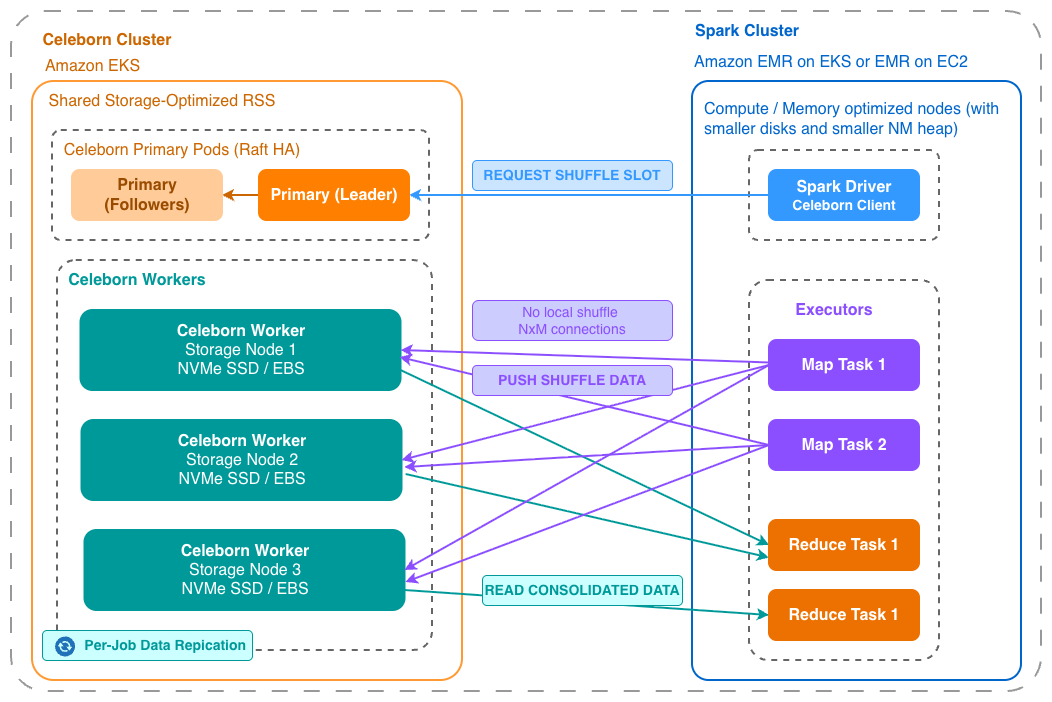
Push-based remote shuffle service where Spark executors on Amazon EMR push shuffle data to a shared Celeborn cluster

Image 1: Push-based Remote Shuffle Service for Spark on EMR

Overview of solution

In this post, we show you how to deploy a Celeborn cluster alongside EMR on EKS and EMR on EC2. The solution also includes an observability stack to provide operational visibility into the Celeborn cluster. Metrics are collected by the AWS Distro for OpenTelemetry (ADOT) collector and routed to two monitoring paths. The AWS managed option uses Amazon Managed Service for Prometheus and Amazon Managed Grafana. The open source option uses self-managed Prometheus with a built-in Grafana.

Apache Celeborn can be deployed in several ways depending on your operational requirements and scale. These two deployment patterns are the main ones:

  • Co-located on the same cluster: Celeborn runs on the same compute environment as Spark. This is the most straightforward operational model, with no cross-cluster networking. The main constraint is shared cluster lifecycle: any upgrade or termination affects Celeborn and running Spark jobs simultaneously.
  • Separate Celeborn cluster: Celeborn runs on its own EC2 or EKS cluster, fully isolated from Spark compute. This is the most operationally flexible model and is the focus of this post.

In this solution, Celeborn runs on a dedicated Amazon Elastic Kubernetes Service (Amazon EKS) cluster, separate from the EMR Spark environments. The two workloads have different resource profiles. Celeborn is storage and network I/O intensive, while Spark is CPU and memory intensive. By separating them, each cluster can use instance types optimized for its workload. It also improves independent lifecycle management, so you can upgrade or scale Celeborn clusters without disrupting Spark jobs, and the other way around.
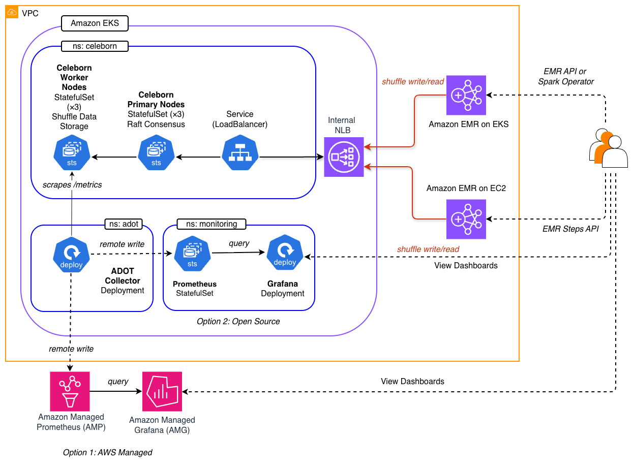
Solution architecture with EMR on EKS and EMR on EC2 connecting to a shared Celeborn cluster through an internal Network Load Balancer

Image 2: Solution Architecture

As the architecture diagram shows, two types of EMR deployment models, EMR on EKS and EMR on EC2, connect to a shared Celeborn cluster through an internal Network Load Balancer (NLB). Behind the scenes, Spark executors register their shuffle partitions to Celeborn workers through this connection, while reducers read consolidated data back during the fetch phase.

The following are the key design considerations for this solution:

  • Streamlined operation by a shared RSS model: Celeborn runs on a dedicated EKS cluster. This provides lifecycle independence, allows each cluster to use workload-optimized instance types, and allows a single Celeborn cluster to serve multiple EMR clusters as a shared service.
  • Cross-cluster connectivity: Clusters reside in the same Amazon Virtual Private Cloud (Amazon VPC) and share private subnets. The AWS Load Balancer Controller on the Celeborn cluster provisions an internal NLB exposing its active primary pods on ports 9097 (RPC) and 9098 (dashboard). The NLB DNS name is VPC-resolvable, so any EMR cluster in the same VPC can reach Celeborn by setting spark.celeborn.master.endpoints to the NLB address.
  • Restricted and secured networking: The Celeborn cluster only allows inbound traffic from the EMR on EC2 and EMR on EKS clusters, sending shuffle data and metrics over the network to the Celeborn cluster.
  • State persistence: Primary nodes maintain Celeborn’s coordination state through Raft consensus, which requires storage that survives pod restarts. Deploying them as StatefulSets with EBS-backed persistent volume claims (PVC) lets a restarted primary pod recover its Raft log and identity from durable storage rather than starting from scratch. Workers keep shuffle data on local NVMe instance store for performance, but this is ephemeral. To protect data loss on workers, each shuffle partition is replicated to two other workers by setting spark.celeborn.client.push.replicate.enabled=true.
  • Observability: ADOT collector is deployed on the Celeborn EKS cluster. It scrapes Prometheus metrics from Celeborn’s pods, and simultaneously remote writes them to two monitoring backends. Option 1 uses Amazon Managed Service for Prometheus as the metrics store, with Amazon Managed Grafana surfacing pre-built dashboards for Celeborn cluster health and Java Virtual Machine (JVM) metrics. This option requires AWS IAM Identity Center. Option 2 deploys a self-managed Prometheus stack with a built-in Grafana on the Celeborn EKS cluster, with Prometheus configured as a remote-write receiver for the same ADOT collector. This option suits environments without IAM Identity Center or those preferring a single open-source tooling.

Critical configurations

The following two tables list the key configurations that make up the solution.

  • Spark configuration (RSS client): Tells the Spark client to use Celeborn as the shuffle manager in place of Spark’s built-in implementation.
  • Celeborn configuration (RSS server): Controls how the primary and worker Celeborn pods operate on Kubernetes.

Note: The values in the following tables are reference defaults used in this walkthrough. Adjust them based on your workload requirements and cluster sizing.

1. Spark configuration (RSS client)

The following table highlights some key Spark configurations required to use Celeborn as the shuffle manager. You can refer to these configurations applied for each Spark submission method in the scripts below:

Parameter Value Purpose
spark.shuffle.service.enabled false Disables Spark’s built-in External Shuffle Service. Must be off before Celeborn can take its place
spark.shuffle.manager org.apache.spark.shuffle.celeborn.SparkShuffleManager Replaces Spark’s default SortShuffleManager with Celeborn’s shuffle manager
spark.celeborn.master.endpoints <NLB_DNS>:9097 Points Spark to the Celeborn primary RPC endpoint through the internal NLB. You can add multiple NLB addresses here, separated by a comma.
spark.shuffle.sort.io.plugin.class org.apache.spark.shuffle.celeborn.CelebornShuffleDataIO Registers Celeborn’s data I/O plugin alongside the shuffle manager
spark.celeborn.client.push.replicate.enabled true

Default: false

OPTIONAL: if shuffle performance has a higher priority than job stability, turn off the data replication at a job level. This setting replicates shuffle data across multiple Celeborn workers for fault tolerance.

spark.celeborn.client.spark.push.unsafeRow.fastWrite.enabled false Default: true COMPULSORY: Disables Celeborn’s optimization for UnsafeRow, making it compatible with the optimized Spark runtime in EMR
spark.dynamicAllocation.shuffleTracking.enabled false Default: true COMPULSORY: Disables shuffle tracking.
spark.sql.adaptive.localShuffleReader.enabled false

Default: true.

COMPULSORY: makes sure Spark does not use local shuffle readers to read the shuffle data.

spark.celeborn.client.spark.shuffle.fallback.policy NEVER

Default: AUTO.

COMPULSORY: to make sure we don’t see intermittent writes to local and remote shuffles.

2. Celeborn configuration (RSS server)

The following table provides the server-side settings that control how the Celeborn primary and worker pods operate on Kubernetes. These values are set in the Helm values.yaml file.

Parameter Value Purpose
master.replicas 3 Number of Celeborn primary node replicas for HA. A minimum 3 required for Raft quorum
worker.replicas 3 Number of Celeborn workers to store shuffle data, should be less than EC2 node number.
master.volumeClaimTemplates gp3, 5 GiB Persistent storage for Raft consensus state
worker.volumes 4 × hostPath (/mnt/nvme/disk1-4) Shuffle data stored on local NVMe instance store is ephemeral but significantly faster than Amazon Elastic Block Store (EBS) volumes for shuffle I/O
master/worker tolerations celeborn-dedicated Schedules Celeborn pods only on dedicated tainted nodes
master/worker podAntiAffinity preferred, w=100 Spreads replicas across different nodes to limit failure blast radius
image.tag 0.6.2 Pinned Apache Celeborn version

Deploy the solution

This solution contains six layers, each of which is dependent on the previous deployments. See the details in the following deployment steps:

  • Shared Infrastructure (Step 2).
  • Celeborn Remote Shuffle Service installation (Step 3).
  • Prepares sample data and creates EMR compute (Step 4, 5).
  • Observability Layer (Step 6-7 and Step 9).
  • Submit job (Step 8).
  • Cleanup (Step 10).

Note: This walkthrough creates billable AWS resources, including Amazon EKS clusters, EC2 instances, Amazon Managed Grafana, Amazon Managed Service for Prometheus, and a Network Load Balancer. To avoid ongoing charges, follow the cleanup instructions at the end of this post.

Prerequisites

Before you deploy this solution, make sure the following prerequisites are in place:

Deployment steps

Step 1: Clone from the source repository

Clone the repository to your local machine and set the AWS_REGION:

git clone https://github.com/aws-samples/sample-emr-celeborn-shuffle-service.git
cd sample-emr-celeborn-shuffle-service
export AWS_REGION=<AWS_REGION>

Step 2: Deploy the shared infrastructure

This step creates the core AWS resources, including the VPC, AWS Key Management Service (AWS KMS) key, security groups, and Amazon Simple Storage Service (Amazon S3) bucket.

./shared-infra/deploy.sh

Step 3: Deploy the Celeborn cluster

This step provisions a dedicated EKS cluster for Celeborn and exposes it through an internal NLB. It follows security best practices by keeping the EKS endpoint private, allowing public access only from a deployment workstation IP, and enabling encryption for secrets plus logging for all cluster components.

./celeborn/deploy.sh

Step 4: Prepare the sample data

Execute the following script to generate sample data:

./spark-jobs/setup-data.sh

Step 5. Deploy a compute engine (choose one or both)

Create at least one of the following EMR deployment models to run Spark jobs.

Option A: EMR on EKS

./emr-on-eks/deploy.sh

Option B: EMR on EC2

./emr-on-ec2/deploy.sh

Step 6. Deploy observability

To monitor the Celeborn cluster, deploy one of the observability options. After deployment, a Grafana URL and login details are available in the .environment-info file located at the repository’s root directory. Follow the instructions in Step 9 to sign in to your Grafana dashboard. You will see two pre-built dashboards on the Grafana web UI:

  • Celeborn Cluster Overview: Active shuffles, worker status, disk usage, and memory utilization.
  • Celeborn JVM Metrics: Heap usage, garbage collection, and thread activity.

Option A: AWS managed services

This option deploys an Amazon Managed Service for Prometheus workspace for metrics storage and an Amazon Managed Grafana workspace to host dashboards. Amazon Managed Grafana requires IAM Identity Center, so first enable it at the organization level and create an SSO user:

export SSO_USER_EMAIL=<your-email>
./observability/amp-amg/setup-sso.sh

Then deploy the stack:

./observability/amp-amg/deploy.sh

Option B: Open-source tool

This option deploys a Prometheus stack, including a built-in Grafana service, onto the Celeborn EKS cluster in the monitoring namespace.

./observability/prometheus-grafana/deploy.sh

Step 7: Deploy ADOT Collector

The ADOT collector scrapes Prometheus metrics from Celeborn pods and remote-writes them to all active monitoring backends: Amazon Managed Service for Prometheus, open-source Prometheus, or both.

./observability/adot/deploy.sh

Step 8: Submit a Spark job

The sample job is a PySpark word-count application that creates shuffle through groupBy and orderBy operations. Both EMR deployment options below are configured with Celeborn as the shuffle manager.

Option A: Using EMR on EKS

Submit the job using the StartJobRun API:

./emr-on-eks/submit-emr-api.sh

This code snippet shows the core part of the script (see the full version):

aws emr-containers start-job-run
  --virtual-cluster-id "${VIRTUAL_CLUSTER_ID}"
  --name "${job_name}"
  --execution-role-arn "${JOB_EXECUTION_ROLE_ARN}"
  --release-label "${EMR_RELEASE_LABEL}"
  --job-driver "{
    "sparkSubmitJobDriver": {
      "entryPoint": "${input_path}",
      "entryPointArguments": ["${data_input}", "${data_output}"],
      "sparkSubmitParameters": "
        --conf spark.shuffle.manager= \
        org.apache.spark.shuffle.celeborn.SparkShuffleManager
        ...
      "
    }
  }"

Alternatively, submit the job using a Spark Operator:

./emr-on-eks/submit-spark-operator.sh

The script automatically generates a SparkApplication manifest then applies it to EMR on EKS. For example, kubectl apply -f your-job-manifest-name.yaml

Option B: Using EMR on EC2

Submit the job as an EMR Step through the Steps API:

./emr-on-ec2/submit-job.sh

The following snippet shows the core API call used by the script:

aws emr add-steps
  --cluster-id "${CLUSTER_ID}"
  --region "${AWS_REGION}"
  --steps "Type=Spark,
  Name=${JOB_NAME},
  ActionOnFailure=CONTINUE,
  Args=[
    --deploy-mode,client,
    --conf,spark.shuffle.manager= \
    org.apache.spark.shuffle.celeborn.SparkShuffleManager,
    ...
  ]"

Step 9: Review the Grafana dashboard for remote shuffle metrics

The Grafana endpoint is dynamically generated at deploy time and is unique to your deployment. To access it, open the .environment-info file at the repository root. This file contains the Grafana URL along with login instructions. Sign in using the credentials listed there, then navigate to the Celeborn Cluster Overview dashboard to observe remote shuffle metrics in real time. A sample Grafana dashboard screenshot is shown below:
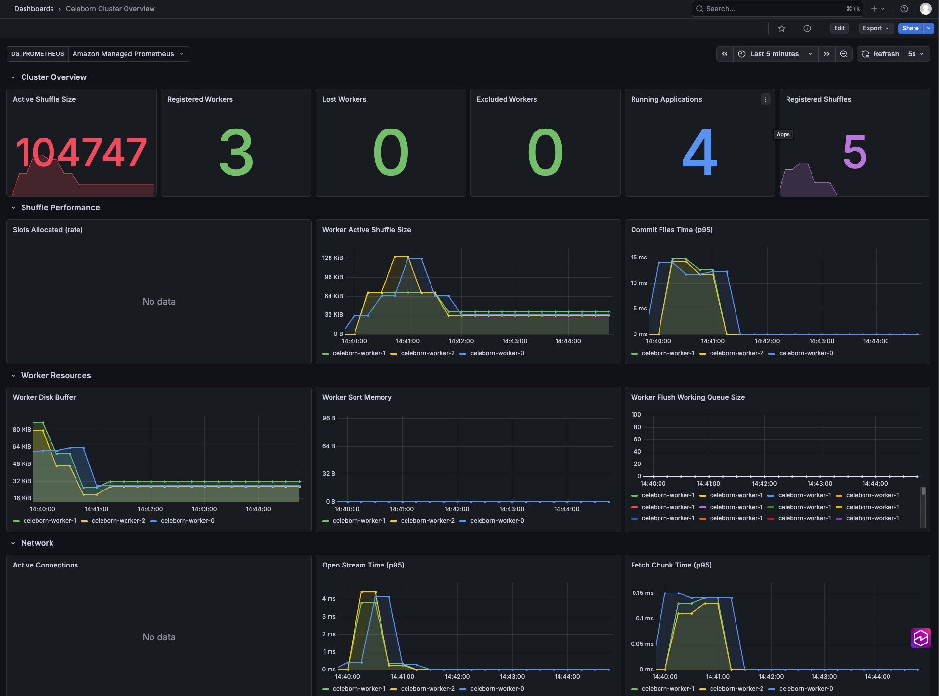
Grafana dashboard showing Celeborn remote shuffle metrics, including active shuffles and worker status

Image 3: Grafana dashboard for Celeborn Metrics

Step 10. Cleaning up

To avoid incurring future charges, run the cleanup script from the root directory:

./teardown.sh

This script detects which components are deployed and tears them down in reverse dependency order, automatically skipping components that are not present. Shared infrastructure is always deleted last, since other components depend on it.

WARNING: This will permanently remove all resources created previously, including any data stored in S3 buckets and configurations. The action cannot be undone. Make sure you have backed up any data you wish to retain before proceeding.

Considerations for production implementation

This post demonstrates a working end-to-end architecture for integrating Celeborn with Amazon EMR. Before taking this pattern to production, consider the following areas.

1. Security

The following considerations help you secure a Celeborn deployment across data isolation, encryption, and access control.

1.1. Shuffle data isolation between teams

Celeborn partitions shuffle data by application ID, which is designed to prevent jobs from accidentally reading each other’s data. This is sufficient when all jobs share the same trust boundary. For multi-team deployments where data privacy is required, a dedicated Celeborn cluster per team is the most effective isolation boundary: each team gets its own NLB and security group, and shuffle data never co-mingles at the infrastructure level.

1.2. Data in transit

In our implementation, shuffle data travels over plain TCP between Spark executors and Celeborn workers. Access is restricted to nodes using security groups. The internal NLB isn’t reachable outside the VPC, and security group rules block all other intra-VPC traffic.

For workloads requiring encryption in transit, Celeborn supports TLS on both RPC and data channels through the celeborn.ssl.* configuration. This is a cluster-wide setting that applies to all jobs on the cluster and must be enabled server-side in celeborn-defaults.conf.

1.3. Data at rest

EBS volumes (used for Celeborn leader pod Raft state) are encrypted with the shared AWS KMS key. NVMe instance store volumes on Celeborn worker nodes are ephemeral and not encrypted by default. Shuffle data written to NVMe is not protected by AWS KMS. For compliance requirements mandating encryption at rest, consider using EBS-backed worker storage instead of instance store, where worker pods mount PersistentVolumeClaim (through volumeClaimTemplates) that reference the encrypted gp3 StorageClass. This comes at the cost of lower I/O throughput compared to local NVMe.

1.4. EKS secrets encryption

EKS clusters encrypt Kubernetes secrets at rest using AWS KMS (EncryptionConfig in the cluster CloudFormation templates). This covers Kubernetes API objects but not application-level shuffle data.

1.5. Application-level authorization

Our deployment enforces access control in the network layer (that is, VPC and security group rules). Celeborn also provides an application-level authorization framework, which is disabled by default. Turning it on adds a second level of security control where only applications presenting valid credentials can register with the cluster. This is recommended for production deployments where multiple workloads or teams share the same VPC subnets, ensuring that network proximity alone does not grant shuffle service access.

Configuration for the Celeborn server:

celeborn.auth.enabled true # Enable SASL application authentication
celeborn.internal.port.enabled true # Required when enabling SASL authentication

Configuration to enable authentication in every Spark app:

--conf spark.celeborn.auth.enabled=true

2. Autoscaling

You can scale Celeborn workers or primary pods using kubectl. For example:

kubectl scale statefulsets celeborn-worker -n celeborn --replicas=6
kubectl scale statefulsets celeborn-master -n celeborn --replicas=2
  • Celeborn workers register with a primary node when they start, so scaling out is safe even while the cluster is running. Scaling in, however, requires more care. Removing a worker pod during an active job may cause shuffle data loss unless celeborn.client.push.replicate.enabled=true is enabled. To reduce the risk of accidental disruption during node scale-in or upgrades, add a Pod Disruption Budget to prevent multiple workers from being evicted at the same time.
  • Spark executors: Dynamic Resource Allocation (DRA) is enabled in sample Spark jobs (spark.dynamicAllocation.enabled=true). This means the number of executors can scale automatically within the configured minExecutors and maxExecutors range.

3. Resiliency

  • Primary Node HA: 3-replica Raft quorum with EBS-backed durable state is designed to tolerate one leader node failure without job interruption.
  • Worker replication: the setting celeborn.client.push.replicate.enabled=true copies each shuffle partition to two workers, designed to tolerate a single worker failure mid-job. Without replication, a worker failure causes a fetch failure and job retry.
  • Pod Disruption Budgets (PDB): not configured in this demo. Add PDBs for Celeborn’s StatefulSets to prevent simultaneous eviction during node upgrades or scale-in.
  • Multi-AZ placement: podAntiAffinity (preferred, weight 100) spreads pods across nodes and Availability Zones. For strict Availability Zone isolation, switch to requiredDuringSchedulingIgnoredDuringExecution.

4. Monitoring and alerting

Consider extending the Grafana dashboards with the alerting rules on:

  • Active shuffle partition count: indicator of job load.
  • Worker disk utilization: prevent shuffle storage exhaustion.
  • Push failure rate: early signal of connectivity or capacity issues.
  • Celeborn primary node failover: leadership changes indicate Raft instability.

Conclusion

In this post, we showed how to deploy Apache Celeborn as a Remote Shuffle Service on Amazon EKS and integrate it with Amazon EMR on EKS and Amazon EMR on EC2. By decoupling shuffle storage from Spark’s compute, this architecture delivers resilience to node failures, eliminates disk contention, and enables independent scaling of storage and compute tiers.

Running Celeborn on a dedicated cluster gives you lifecycle independence from Spark, lets multiple EMR clusters share a single shuffle service, and provides fault tolerance through push-based shuffling, Raft-based high availability, and per-job data replication. It also provides automatic fallback to Spark’s built-in shuffle during maintenance windows. Stop choosing between cost and reliability. With Celeborn on Amazon EMR, you get both.

For more information, see the Amazon EMR on EKS documentation and the Apache Celeborn documentation. To explore the full implementation, visit the aws-samples GitHub repository. If you have questions or feedback, leave us a comment.
About the authors

Suvojit Dasgupta

Suvojit Dasgupta

Suvojit is a Principal Architect at AWS, where he leads engineering teams delivering large-scale data and analytics solutions for some of AWS’s largest enterprise customers. He specializes in designing modern data platforms, real-time streaming architectures, and cloud-native analytics systems that allow organizations to process data at petabyte scale while optimizing performance and cost. His technical interests include distributed data systems, containerized analytics platforms, and building high-performance data infrastructure that uses Kubernetes and cloud-native technologies to power a wide variety of analytics workloads.

Melody Yang

Melody Yang

Melody is a Principal Analytics Architect for Amazon EMR at AWS. She is an experienced analytics leader working with AWS customers to provide best practice guidance and technical advice in order to assist their success in data transformation. Her areas of interests are open-source frameworks and automation, data engineering and DataOps.

Vishal Vyas

Vishal Vyas

Vishal is a Principal Software Engineer for Amazon EMR, where he provides engineering leadership across all three Amazon EMR services: EMR on EC2, EMR on EKS, and EMR Serverless. With more than 17 years of industry experience, Vishal specializes in large-scale analytics, generative AI, and distributed systems. He leads the design and implementation of solutions for complex systems that span multiple AWS services and open-source technologies.

Avinash Desireddy

Avinash Desireddy

Avinash is a Specialist Solutions Architect (Containers) at Amazon Web Services (AWS), passionate about building secure applications and data platforms. He has extensive experience in Kubernetes, DevOps, and enterprise architecture, helping customers and partners containerize applications, streamline deployments, and optimize cloud-native environments.

Deploy Apache YuniKorn batch scheduler for Amazon EMR on EKS

Post Syndicated from Suvojit Dasgupta original https://aws.amazon.com/blogs/big-data/deploy-apache-yunikorn-batch-scheduler-for-amazon-emr-on-eks/

As organizations successfully grow their Apache Spark workloads on Amazon EMR on EKS, they may seek to optimize resource scheduling to further enhance cluster utilization, minimize job queuing, and maximize performance. Although Kubernetes’ default scheduler, kube-scheduler, works well for most containerized applications, it lacks feature sets capable of managing complex big data workloads with specific requirements such as gang scheduling, resource quotas, job priorities, multi-tenancy, and hierarchical queue management. This limitation can result in inefficient resource utilization, longer job completion times, and increased operational costs for organizations running large-scale data processing workloads.

Apache YuniKorn addresses these limitations by providing a custom resource scheduler specifically designed for big data and machine learning (ML) workloads running on Kubernetes. Unlike kube-scheduler, YuniKorn offers features such as gang scheduling, making sure all containers of a Spark application start together, resource fairness amongst multiple tenants, priority and preemption capabilities, and queue management with hierarchical resource allocation. For data engineering and platform teams managing large-scale Spark workloads on Amazon EMR on EKS, YuniKorn can improve resource utilization rates, reduce job completion times, and provide improved resource allocation for multi-tenant clusters. This is particularly valuable for organizations running mixed workloads with varying resource requirements, strict SLA requirements, or complex resource sharing policies across different teams and applications.

This post explores Kubernetes scheduling fundamentals, examines the limitations of the default kube-scheduler for batch workloads, and demonstrates how YuniKorn addresses these challenges. We discuss how to deploy YuniKorn as a custom scheduler for Amazon EMR on EKS, its integration with job submissions, how to configure queues and placement rules, and how to establish resource quotas. We also show these features in action through practical Spark job examples.

Understanding Kubernetes scheduling and the need for YuniKorn

In this section, we dive into the details of Kubernetes scheduling and the need for YuniKorn.

How Kubernetes scheduling works

Kubernetes scheduling is the process of assigning pods to nodes within a cluster while considering resource requirements, scheduling constraints, and isolation constraints. The scheduler evaluates each pod individually against all schedulable worker nodes, considering multiple factors, including resource requirements such as CPU, memory and I/O requests, node affinity preferences for specific node characteristics, inter-pod affinity and anti-affinity rules that determine whether the pods should be distributed across multiple worker nodes or require colocation, taints and tolerations that dictate scheduling constraints, and Quality of Service classifications that influence scheduling priority.

The scheduling process operates through a two-phase approach. During the filtering phase, the scheduler identifies all worker nodes that could potentially host the pod by eliminating those that don’t meet the basic requirements. The scoring phase then ranks all feasible worker nodes using scoring algorithms to determine the optimal placement, ultimately selecting the highest-scoring node for pod assignment.

Default implementation of kube-scheduler

kube-scheduler serves as the Kubernetes default scheduler. This scheduler operates on a pod-by-pod basis, treating each scheduling decision as an independent operation without consideration for the broader application context.When kube-scheduler processes scheduling requests, it follows a continuous workflow. The API server is monitored for newly created pods awaiting node assignment, applies filtering logic to eliminate unsuitable worker nodes, executes its scoring algorithm to rank the remaining candidates, binds the selected pod to the optimal node, and repeats the process with the next unscheduled pod in the queue.This individual pod scheduling approach works well for microservices and web applications where each pod has fewer interdependencies. However, this design creates significant challenges when applied to distributed big data frameworks like Spark that require coordinated scheduling of multiple interdependent pods.

Challenges using kube-scheduler for batch jobs

Batch processing workloads, particularly those built on Spark, present different scheduling requirements that expose limitations in kube-scheduler algorithm. Such applications consist of multiple pods that must operate as a cohesive unit, yet kube-scheduler lacks the application-level awareness necessary to handle coordinated scheduling requirements.

Gang scheduling challenges

The most significant challenge emerges from the need for gang scheduling, where all components of a distributed application must be scheduled simultaneously. A typical Spark application requires a driver pod and multiple executor pods running in parallel to function correctly. Without YuniKorn, kube-scheduler first schedules the driver pod without knowing the total amount of resources that the driver and executors will need together. When the driver pod starts running, it attempts to spin up the required executor pods but might fail to find sufficient resources in the cluster. This sequential approach can result in the driver being scheduled successfully while some or all executor pods remain in a pending state due to insufficient cluster capacity.This partial scheduling creates a problematic scenario where the application consumes cluster resources but can’t execute meaningful work. The partially scheduled application will hold onto allocated resources indefinitely while waiting for the missing components, preventing other applications from utilizing those resources and resulting in a deadlock situation.

Resource fragmentation issues

Resource fragmentation represents another critical issue that emerges from individual pod scheduling. When multiple batch applications compete for cluster resources, the lack of coordinated scheduling leads to scenarios where sufficient total resources exist for a given application, but they become fragmented across multiple incomplete applications. This fragmentation prevents efficient resource utilization and can leave applications in perpetual pending states.

The absence of hierarchical queue management further compounds these challenges. kube-scheduler provides limited support for hierarchical resource allocation, making it difficult to implement fair sharing policies across different tenants. Organizations can’t easily establish resource quotas that guarantee minimum allocations while setting maximum limits, nor can they implement preemption policies that allow higher-priority jobs to reclaim resources from lower-priority workloads.

The Need for YuniKorn

YuniKorn addresses these batch scheduling limitations through a set of features designed for distributed computing workloads. Unlike the pod-centric approach of kube-scheduler, YuniKorn operates with application-level awareness, understanding the relationships between different components of distributed applications and making scheduling decisions accordingly. The features are as follows:

  • Gang scheduling for atomic application deployment – Gang scheduling represents YuniKorn’s advantage for batch workloads. This capability makes sure pods belonging to an application are scheduled atomically—either all components receive node assignments, or none are scheduled until sufficient resources become available. YuniKorn’s all-or-nothing approach to scheduling minimizes resource deadlocks and partial application failures that impact kube-scheduler based deployments, resulting in more predictable job execution and higher completion rates.
  • Hierarchical queue management and resource organization – YuniKorn’s queue management system provides the hierarchical resource organization that enterprise batch processing environments require. Organizations can establish multi-level queue structures that mirror their organizational hierarchy, implementing resource quotas at each level to facilitate fair resource distribution. The scheduler supports guaranteed resource allocations that provide minimum resource commitments and maximum limits that prevent a single queue from monopolizing cluster resources.
  • Dynamic resource preemption based on priority – The preemption capabilities built into YuniKorn enable dynamic resource reallocation based on job priorities and queue policies. When higher-priority applications require resources currently allocated to lower-priority workloads, YuniKorn can gracefully stop lower-priority pods and reallocate their resources, making sure critical jobs receive the resources they need without manual intervention.
  • Intelligent resource pooling and fair share distribution – Resource pooling and fair share scheduling further enhance YuniKorn’s effectiveness for batch workloads. Rather than treating each scheduling decision in isolation, YuniKorn considers the broader resource allocation landscape, implementing fair-share algorithms that facilitate equitable resource distribution across different applications and users while maximizing overall cluster utilization.

These features add to the existing capabilities of Amazon EMR on EKS by establishing an enhanced environment in which the unique requirements of distributed computing workloads are satisfied.

Solution overview

Consider HomeMax, a fictitious company operating a shared Amazon EMR on EKS cluster where three teams regularly submit Spark jobs with distinct characteristics and priorities:

  • Analytics team – Runs time-sensitive customer analysis jobs requiring immediate processing for business decisions
  • Marketing team – Executes large overnight batch jobs for campaign optimization with predictable resource patterns
  • Data science team – Runs experimental workloads with varying resource needs throughout the day for model development and research

Without proper resource scheduling, these teams face common challenges: resource contention, job failures due to partial scheduling, and inability to guarantee SLAs for critical workloads.For our YuniKorn demonstration, we configured an Amazon EMR on EKS cluster with the following specifications:

  • Amazon EKS cluster: Four worker nodes using m5.2xlarge Amazon Elastic Compute Cloud (Amazon EC2) instances
  • Per-node resources: 8 vCPUs, 32 GiB memory
  • Total cluster capacity: 32 vCPU cores and 128 GiB memory
  • Available for Spark: Approximately 30 vCPUs and approximately 120 GiB memory (after system overhead)
  • Kubernetes version: 1.30+ (required for YuniKorn 1.6.x compatibility)

The following code shows the node group configuration:

# EKS Node Group specification
NodeGroup:
  InstanceTypes:
    - m5.2xlarge
  ScalingConfig:
    MinSize: 4
    DesiredSize: 4
    MaxSize: 4
  DiskSize: 20
  AmiType: AL2023_x86_64_STANDARD

We intentionally use a fixed-capacity cluster to provide a controlled environment that showcases YuniKorn’s scheduling capabilities with consistent, predictable resources. This approach makes resource contention scenarios more apparent and demonstrates how YuniKorn resolves them.

Amazon EMR on EKS offers robust scaling capabilities through Karpenter. The principles demonstrated in this fixed environment apply equally to dynamic environments, where YuniKorn’s capabilities complement the scaling features of Amazon EMR on EKS to optimize resource utilization during peak demand periods or when scaling limits are reached.

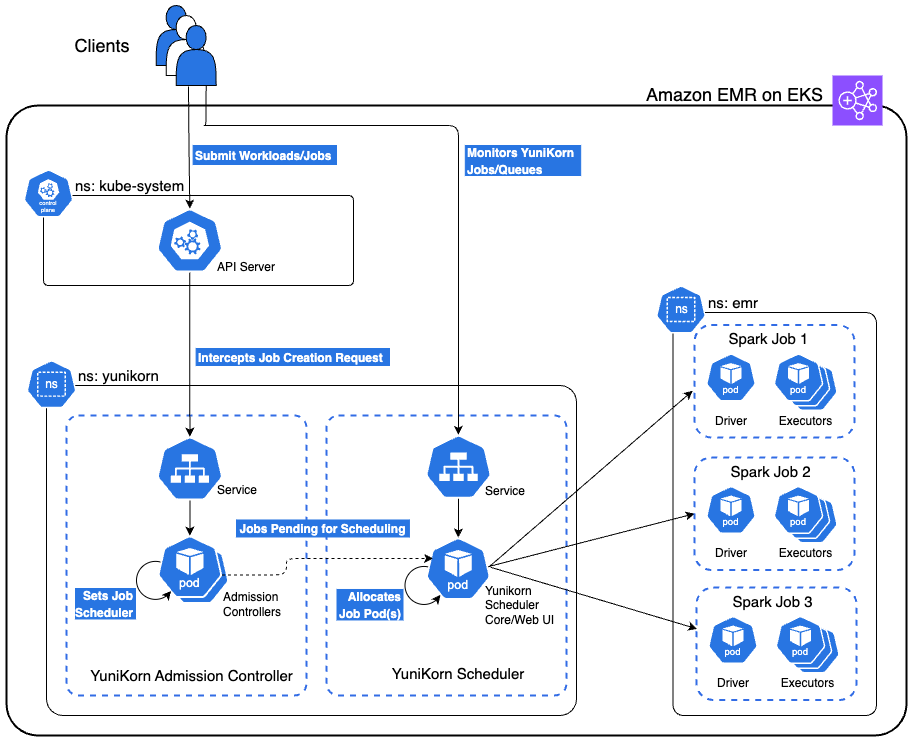
The following diagram shows the high-level architecture of the YuniKorn scheduler running on Amazon EMR on EKS. This solution also includes a secure bastion host not shown in the architecture diagram that provides access to the EKS cluster via AWS Systems Manager (SSM) Session Manager. The bastion host is deployed in a private subnet with all necessary tools pre-installed with proper permissions for seamless cluster interaction.

In the following sections, we explore YuniKorn’s queue architecture optimized for this use case. We examine various demonstration scenarios, including gang scheduling, queue-based resource management, priority-based preemption, and fair share distribution. We walk through the process of deploying an Amazon EMR on EKS cluster, implementing the YuniKorn scheduler, configuring the specified queues, and submitting Spark jobs to showcase these scenarios.

YuniKorn integration on Amazon EMR on EKS

The integration involves three key components working together: the Amazon EMR on EKS virtual cluster configuration, YuniKorn’s admission webhook system, and job-level queue annotations.

Namespace and virtual cluster foundation

The integration begins with a dedicated Kubernetes namespace where your Amazon EMR on EKS jobs will run. In our demonstration, we use the emr namespace, created as a standard Kubernetes namespace:

apiVersion: v1
kind: Namespace
metadata:
  name: emr

The Amazon EMR on EKS virtual cluster is configured to deploy all jobs within this specific namespace. When creating the virtual cluster, you specify the namespace in the container provider configuration:

aws emr-containers create-virtual-cluster \
    --name "emr-on-eks-cluster-v" \
    --container-provider "{
        \"id\": \"my-eks-cluster\",
        \"type\": \"EKS\",
        \"info\": {
            \"eksInfo\": {
                \"namespace\": \"emr\"
            }
        }
    }"

This configuration makes sure all jobs submitted to this virtual cluster will be deployed in the emr namespace, establishing the foundation for YuniKorn integration.

The YuniKorn interception mechanism

When YuniKorn is installed using Helm, it automatically registers a MutatingAdmissionWebhook with the Kubernetes API server. This webhook acts as an interceptor that monitors pod creation events in your designated namespace. The webhook registration tells Kubernetes to call YuniKorn whenever pods are created in the emr namespace:

# YuniKorn registers this webhook configuration
apiVersion: admissionregistration.k8s.io/v1
kind: MutatingAdmissionWebhook
rules:
- operations: ["CREATE"]
  resources: ["pods"]
  namespaces: ["emr"]  # Intercepts pods in EMR namespace

This webhook is triggered by any pod creation in the emr namespace, not specifically by YuniKorn annotations. However, the webhook’s logic only modifies pods that contain YuniKorn queue annotations, leaving other pods unchanged.

End-to-end job flow

When you submit a Spark job through the Spark Operator, the following sequence occurs:

  1. Your Spark job includes YuniKorn queue annotations on both driver and executor pods:
driver:
  annotations:
    yunikorn.apache.org/queue: "root.analytics-queue"
executor:
  annotations:
    yunikorn.apache.org/queue: "root.analytics-queue"
  1. The Spark Operator processes your SparkApplication and creates individual Kubernetes pods for the driver and executors. These pods inherit the YuniKorn annotations from your job template.
  2. When the Spark Operator attempts to create pods in the emr namespace, Kubernetes calls YuniKorn’s admission webhook. The webhook examines each pod and performs the following actions:
    1. Detects pods with yunikorn.apache.org/queue annotations.
    2. Adds schedulerName: yunikorn to those pods.
    3. Leaves pods without YuniKorn annotations unchanged.

This interception means you don’t need to manually specify schedulerName: yunikorn in your Spark jobs—YuniKorn claims the pods transparently based on the presence of queue annotations.

  1. The YuniKorn scheduler receives the scheduling requests and applies the queue placement rules configured in the YuniKorn ConfigMap:
placementrules:
  - name: provided    # Uses the annotation value
    create: false.    # Doesn’t create the queue if not present
  - name: fixed       # Fallback to root.default queue
    value: root.default

The provided rule reads the yunikorn.apache.org/queue annotation and places the job in the specified queue (for example, root.analytics-queue). YuniKorn then applies gang scheduling logic, holding all pods until sufficient resources are available for the entire application, preventing the partial scheduling issues that come with kube-scheduler.

  1. After YuniKorn determines that all pods can be scheduled according to the queue’s resource guarantees and limits, it schedules all driver and executor pods. The Spark job begins execution with the guaranteed resource allocation defined in the queue configuration.

The combination of namespace-based virtual cluster configuration, admission webhook interception, and annotation-driven queue placement creates an integration that transforms Amazon EMR on EKS job scheduling without disrupting existing workflows.

YuniKorn queue architecture

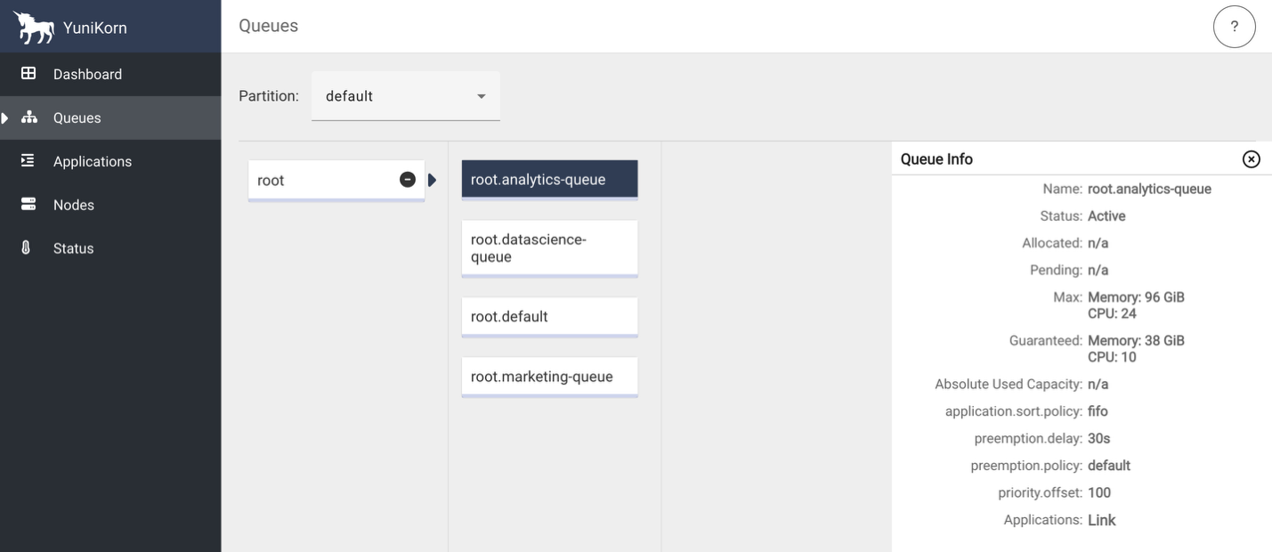
To demonstrate the various YuniKorn features described in the next section, we configured three job-specific queues and a default queue representing our enterprise teams with carefully balanced resource allocations:

# Analytics Queue - Time-sensitive workloads
analytics-queue:
  guaranteed: 10 vCPUs, 38GB memory (30% of cluster)
  max: 24 vCPUs, 96GB memory (80% burst capacity)
  priority: 100 (highest)
  policy: FIFO (predictable scheduling)
# Marketing Queue - Large batch jobs
marketing-queue:
  guaranteed: 8 vCPUs, 32GB memory (25% of cluster)
  max: 24 vCPUs, 96GB memory (80% burst capacity)
  priority: 75 (medium)
  policy: Fair Share (balanced resource distribution)
# Data Science Queue - Experimental workloads
datascience-queue:
  guaranteed: 6 vCPUs, 26GB memory (20% of cluster)
  max: 24 vCPUs, 96GB memory (80% burst capacity)
  priority: 50 (lower)
  policy: Fair Share (experimental workload balancing)
# Default Queue - Fallback for unmatched jobs
default:
  guaranteed: 6 vCPUs, 26GB memory (20% of cluster)
  max: 24 vCPUs, 96GB memory (80% burst capacity)
  priority: 25 (lowest)
  policy: FIFO (predictable job submission)

Demonstration scenarios

This section outlines key YuniKorn scheduling capabilities and their corresponding Spark job submissions. These scenarios demonstrate guaranteed resource allocation and burst capacity usage. Guaranteed resources represent minimum allocations that queues can always access, but jobs might exceed these allocations when additional cluster capacity is available. The marketing-job specifically demonstrates burst capacity usage beyond its guaranteed allocation.

  • Gang scheduling – In this scenario, we submit analytics-job.py (analytics-queue, 9 total cores) and marketing-job.py (marketing-queue, 17 total cores) simultaneously. YuniKorn makes sure all pods for each job are scheduled atomically, preventing partial resource allocation that could cause job failures in our resource-constrained cluster.
  • Queue-based resource management – We run all three jobs concurrently to observe guaranteed resource allocation. YuniKorn distributes remaining capacity proportionally based on queue weights and maximum limits.
    • analytics-job.py (analytics-queue) receives guaranteed 10 vCPUs and 38 GB memory.
    • marketing-job.py (marketing-queue) receives guaranteed 8 vCPUs and 32 GB memory.
    • datascience-job.py (datascience-queue) receives guaranteed 6 vCPUs and 26 GB memory.
  • Priority-based preemption – We start datascience-job.py (datascience-queue, priority 25) and marketing-job.py (marketing-queue, priority 50) consuming cluster resources, then submit high-priority analytics-job.py (analytics-queue, priority 100). YuniKorn preempts lower-priority jobs to make sure the time-sensitive analytics workload gets its guaranteed resources, maintaining SLA compliance.
  • Fair share distribution – We submit multiple jobs to each queue when all queues have available capacity. YuniKorn applies configured fair share policies within queues—the analytics queue uses First In, First Out (FIFO) method for predictable scheduling, and the marketing and data science queues use fair sharing method for balanced resource distribution.

Source code

You can find the codebase in the AWS Samples GitHub repository.

Prerequisites

Before you deploy this solution, make sure the following prerequisites are in place:

Set up the solution infrastructure

Complete the following steps to set up the infrastructure:

  1. Clone the repository to your local machine and set the two environment variables. Replace <AWS_REGION> with the AWS Region where you want to deploy these resources.
git clone https://github.com/aws-samples/sample-emr-eks-yunikorn-scheduler.git
cd sample-emr-eks-yunikorn-scheduler
export REPO_DIR=$(pwd)
export AWS_REGION=<AWS_REGION>
  1. Execute the following script to create the infrastructure:
cd $REPO_DIR/infrastructure
./setup-infra.sh
  1. To verify successful infrastructure deployment, open the AWS CloudFormation console, choose your stack, and check the Events, Resources, and Outputs tabs for completion status, details, and list of resources created.

Deploy YuniKorn on Amazon EMR on EKS

Run the following script to deploy the Yunikorn helm chart and update the configmap with the queues and placement rules:

cd $REPO_DIR/yunikorn/
./setup-yunikorn.sh

Establish EKS cluster connectivity

Complete the following steps to establish secure connectivity to your private EKS cluster:

  1. Execute the following script in a new terminal window. This script establishes port forwarding through the bastion host to make your private EKS cluster accessible from your local machine. Keep this terminal window open and running throughout your work session. The script maintains the connection to your EKS cluster.
export REPO_DIR=$(pwd)
export AWS_REGION=<AWS_REGION>
cd $REPO_DIR/port-forward
./eks-connect.sh --start
  1. Test kubectl connectivity in the main terminal window to verify that you can successfully communicate with the EKS cluster. You should see the EKS worker nodes listed, confirming that the port forwarding is working correctly.

kubectl get nodes

Verify successful YuniKorn deployment

Complete the following steps to verify a successful deployment:

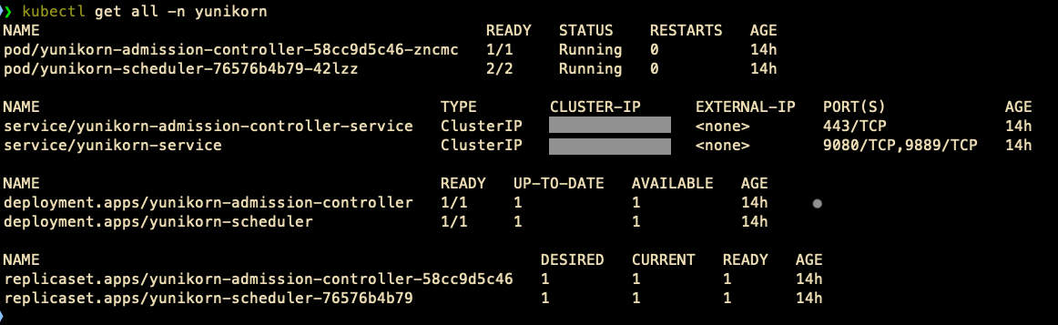
  1. List all Kubernetes objects in the yunikorn namespace:

kubectl get all -n yunikorn

You will see details like the following screenshot.

  1. Check the YuniKorn scheduler logs for configuration loading and look for queue configuration messages:
kubectl logs -n yunikorn deployment/yunikorn-scheduler --tail=50
kubectl logs -n yunikorn deployment/yunikorn-scheduler | grep -i queue
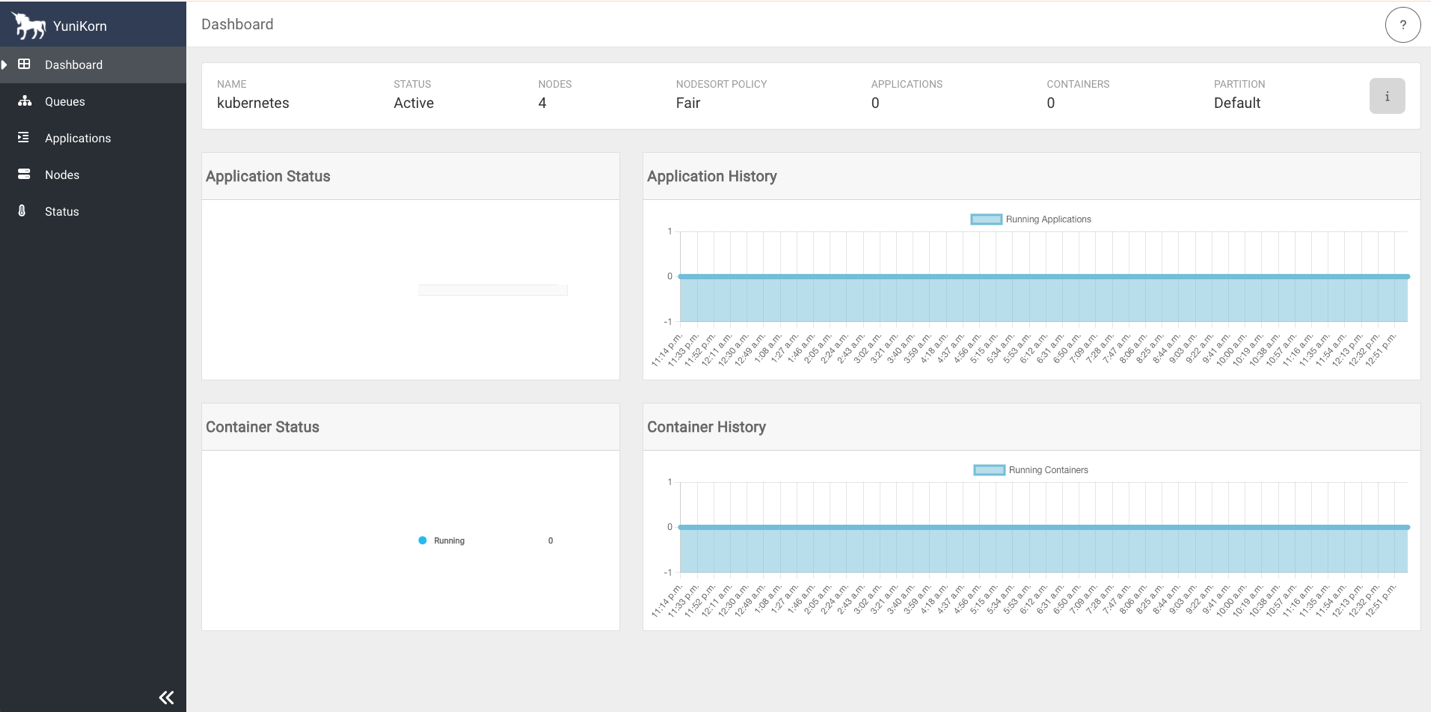
  1. Access the YuniKorn web UI by navigating to http://127.0.0.1:9889 in your browser. Port 9889 is the default port for the YuniKorn web UI.
# macOS
open http://127.0.0.1:9889
# Linux
xdg-open http://127.0.0.1:9889
# Windows
start http://127.0.0.1:9889

The following screenshots show the YuniKorn web UI with queues but no running applications.

Run Spark jobs with YuniKorn on Amazon EMR on EKS

Complete the following steps to run Spark jobs with YuniKorn on Amazon EMR on EKS:

  1. Execute the following script to set up the Spark jobs environment. The script uploads PySpark scripts to Amazon Simple Storage Service (Amazon S3) bucket locations and creates ready-to-use YAML files from templates.
cd $REPO_DIR/spark-jobs
./setup-spark-jobs.sh
  1. Submit analytics, marketing, and data science Spark jobs using the following commands. YuniKorn will place the jobs in their respective queues and allocate resources to execution. Refer to Using YuniKorn as a custom scheduler for Apache Spark on Amazon EMR on EKS for supported job submission methods with YuniKorn as a custom scheduler.
kubectl apply -f spark-operator/analytics-job.yaml
kubectl apply -f spark-operator/marketing-job.yaml
kubectl apply -f spark-operator/datascience-job.yaml
  1. Review the previous section describing different demonstration scenarios and submit the Spark jobs using various combinations to see YuniKorn scheduler’s capabilities in action. We encourage you to adjust the cores, instances, and memory parameters and explore the scheduler’s behavior by executing the jobs. We also encourage you to modify the queues’ guaranteed and max capacities in the file yunikorn/queue-config-provided.yaml, apply the changes, and submit jobs to further understand Yunikorn scheduler behavior under various circumstances.

Clean up

To avoid incurring future charges, complete the following steps to delete the resources you created:

  1. Stop the port forwarding sessions:
cd $REPO_DIR/port-forwarding
./eks-connect.sh --stop
  1. Remove all created AWS resources:
cd $REPO_DIR
./cleanup.sh

Conclusion

YuniKorn addresses the scheduling limitations of default kube-scheduler while running Spark workloads on Amazon EMR on EKS through gang scheduling, intelligent queue management, and priority-based resource allocation. This post showed how YuniKorn’s queue system enables better resource utilization, prevents job failure due to poor allocation of resources, and supports multi-tenant environments.

To get started with YuniKorn on Amazon EMR on EKS, explore the Apache YuniKorn documentation for implementation guides, review Amazon EMR on EKS best practices for optimization strategies, and engage with the YuniKorn community for ongoing support.


About the authors

Suvojit Dasgupta is a Principal Data Architect at Amazon Web Services. He leads a team of skilled engineers in designing and building scalable data solutions for diverse customers. He specializes in developing and implementing innovative data architectures to address complex business challenges.

Peter Manastyrny is a Senior Product Manager at AWS Analytics. He leads Amazon EMR on EKS, a product that makes it straightforward and efficient to run open-source data analytics frameworks such as Spark on Amazon EKS.

Matt Poland is a Senior Cloud Infrastructure Architect at Amazon Web Services. He is passionate about solving complex problems and delivering well-structured solutions for diverse customers. His expertise spans across a range of cloud technologies, providing scalable and reliable infrastructure tailored to each project’s unique challenges.

Gregory Fina is a Principal Startup Solutions Architect for Generative AI at Amazon Web Services, where he empowers startups to accelerate innovation through cloud adoption. He specializes in application modernization, with a strong focus on serverless architectures, containers, and scalable data storage solutions. He is passionate about using generative AI tools to orchestrate and optimize large-scale Kubernetes deployments, as well as advancing GitOps and DevOps practices for high-velocity teams. Outside of his customer-facing role, Greg actively contributes to open source projects, especially those related to Backstage.

Configure Hadoop YARN CapacityScheduler on Amazon EMR on Amazon EC2 for multi-tenant heterogeneous workloads

Post Syndicated from Suvojit Dasgupta original https://aws.amazon.com/blogs/big-data/configure-hadoop-yarn-capacityscheduler-on-amazon-emr-on-amazon-ec2-for-multi-tenant-heterogeneous-workloads/

Apache Hadoop YARN (Yet Another Resource Negotiator) is a cluster resource manager responsible for assigning computational resources (CPU, memory, I/O), and scheduling and monitoring jobs submitted to a Hadoop cluster. This generic framework allows for effective management of cluster resources for distributed data processing frameworks, such as Apache Spark, Apache MapReduce, and Apache Hive. When supported by the framework, Amazon EMR by default uses Hadoop YARN. Please note that not all frameworks offered by Amazon EMR use Hadoop YARN, such as Trino/Presto and Apache HBase.

In this post, we discuss various components of Hadoop YARN, and understand how components interact with each other to allocate resources, schedule applications, and monitor applications. We dive deep into the specific configurations to customize Hadoop YARN’s CapacityScheduler to increase cluster efficiency by allocating resources in a timely and secure manner in a multi-tenant cluster. We take an opinionated look at the configurations for CapacityScheduler and configure them on Amazon EMR on Amazon Elastic Compute Cloud (Amazon EC2) to solve for the common resource allocation, resource contention, and job scheduling challenges in a multi-tenant cluster.

We dive deep into CapacityScheduler because Amazon EMR uses CapacityScheduler by default, and CapacityScheduler has benefits over other schedulers for running workloads with heterogeneous resource consumption.

Solution overview

Modern data platforms often run applications on Amazon EMR with the following characteristics:

  • Heterogeneous resource consumption patterns by jobs, such as computation-bound jobs, I/O-bound jobs, or memory-bound jobs
  • Multiple teams running jobs with an expectation to receive an agreed-upon share of cluster resources and complete jobs in a timely manner
  • Cluster admins often have to cater to one-time requests for running jobs without impacting scheduled jobs
  • Cluster admins want to ensure users are using their assigned capacity and not using others
  • Cluster admins want to utilize the resources efficiently and allocate all available resources to currently running jobs, but want to retain the ability to reclaim resources automatically should there be a claim for the agreed-upon cluster resources from other jobs

To illustrate these use cases, let’s consider the following scenario:

  • user1 and user2 don’t belong to any team and use cluster resources periodically on an ad hoc basis
  • A data platform and analytics program has two teams:
    • A data_engineering team, containing user3
    • A data_science team, containing user4
  • user5 and user6 (and many other users) sporadically use cluster resources to run jobs

Based on this scenario, the scheduler queue may look like the following diagram. Take note of the common configurations applied to all queues, the overrides, and the user/groups-to-queue mappings.

Capacity Scheduler Queue Setup

In the subsequent sections, we will understand the high-level components of Hadoop YARN, discuss the various types of schedulers available in Hadoop YARN, review the core concepts of CapacityScheduler, and showcase how to implement this CapacityScheduler queue setup on Amazon EMR (on Amazon EC2). You can skip to Code walkthrough section if you are already familiar with Hadoop YARN and CapacityScheduler.

Overview of Hadoop YARN

At a high level, Hadoop YARN consists of three main components:

  • ResourceManager (one per primary node)
  • ApplicationMaster (one per application)
  • NodeManager (one per node)

The following diagram shows the main components and their interaction with each other.

Apache Hadoop Yarn Architecture Diagram1

Before diving further, let’s clarify what Hadoop YARN’s ResourceContainer (or container) is. A ResourceContainer represents a collection of physical computational resources. It’s an abstraction used to bundle resources into distinct, allocatable unit.

ResourceManager

The ResourceManager is responsible for resource management and making allocation decisions. It’s the ResourceManager’s responsibility to identify and allocate resources to a job upon submission to Hadoop YARN. The ResourceManager has two main components:

  • ApplicationsManager (not to be confused with ApplicationMaster)
  • Scheduler

ApplicationsManager

The ApplicationsManager is responsible for accepting job submissions, negotiating the first container for running ApplicationMaster, and providing the service for restarting the ApplicationMaster on failure.

Scheduler

The Scheduler is responsible for scheduling allocation of resources to the jobs. The Scheduler performs its scheduling function based on the resource requirements of the jobs. The Scheduler is a pluggable interface. Hadoop YARN currently provides three implementations:

  • CapacityScheduler – A pluggable scheduler for Hadoop that allows for multiple tenants to securely share a cluster such that jobs are allocated resources in a timely manner under constraints of allocated capacities. The implementation is available on GitHub. The Java concrete class is org.apache.hadoop.yarn.server.resourcemanager.scheduler.capacity.CapacityScheduler. In this post, we primarily focus on CapacityScheduler, which is the default scheduler on Amazon EMR (on Amazon EC2).
  • FairScheduler – A pluggable scheduler for Hadoop that allows Hadoop YARN applications to share resources in clusters fairly. The implementation is available on GitHub. The Java concrete class is org.apache.hadoop.yarn.server.resourcemanager.scheduler.fair.FairScheduler.
  • FifoScheduler – A pluggable scheduler for Hadoop that allows Hadoop YARN applications share resources in clusters in a first-in-first-out basis. The implementation is available on GitHub. The Java concrete class is org.apache.hadoop.yarn.server.resourcemanager.scheduler.fifo.FifoScheduler.

ApplicationMaster

Upon negotiating the first container by ApplicationsManager, the per-application ApplicationMaster has the responsibility of negotiating the rest of the appropriate resources from the Scheduler, tracking their status, and monitoring progress.

NodeManager

The NodeManager is responsible for launching and managing containers on a node.

Hadoop YARN on Amazon EMR

By default, Amazon EMR (on Amazon EC2) uses Hadoop YARN for cluster management for the distributed data processing frameworks that support Hadoop YARN as a resource manager, like Apache Spark, Apache MapReduce, and Apache Hive. Amazon EMR provides multiple sensible default settings that work for most scenarios. However, every data platform is different and has specific needs. Amazon EMR provides the ability to customize the setting at cluster creation using configuration classifications . You can also reconfigure Amazon EMR cluster applications and specify additional configuration classifications for each instance group in a running cluster using AWS Command Line Interface (AWS CLI), or the AWS SDK.

CapacityScheduler

CapacityScheduler depends on ResourceCalculator to identify the available resources and calculate the allocation of the resources to ApplicationMaster. The ResourceCalculator is an abstract Java class. Hadoop YARN currently provides two implementations:

  • DefaultResourceCalculator – In DefaultResourceCalculator, resources are calculated based on memory alone.
  • DominantResourceCalculatorDominantResourceCalculator is based on the Dominant Resource Fairness (DRF) model of resource allocation. The paper Dominant Resource Fairness: Fair Allocation of Multiple Resource Types, Ghodsi et al. [2011] describes DRF as follows: “DRF computes the share of each resource allocated to that user. The maximum among all shares of a user is called that user’s dominant share, and the resource corresponding to the dominant share is called the dominant resource. Different users may have different dominant resources. For example, the dominant resource of a user running a computation-bound job is CPU, while the dominant resource of a user running an I/O-bound job is bandwidth. DRF simply applies max-min fairness across users’ dominant shares. That is, DRF seeks to maximize the smallest dominant share in the system, then the second-smallest, and so on.”

Because of DRF, DominantResourceCalculator is a better ResourceCalculator for data processing environments running heterogeneous workloads. By default, Amazon EMR uses DefaultResourceCalculator for CapacityScheduler. This can be verified by checking the value of yarn.scheduler.capacity.resource-calculator parameter in /etc/hadoop/conf/capacity-scheduler.xml.

Code walkthrough

CapacityScheduler provides multiple parameters to customize the scheduling behavior to meet specific needs. For a list of available parameters, refer to Hadoop: CapacityScheduler.

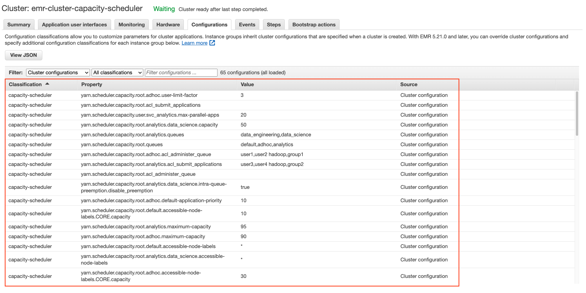
Refer to the configurations section in cloudformation/templates/emr.yaml to review all the CapacityScheduler parameters set as part of this post. In this example, we use two classifiers of Amazon EMR (on Amazon EC2):

  • yarn-site – The classification to update yarn-site.xml
  • capacity-scheduler – The classification to update capacity-scheduler.xml

For various types of classification available in Amazon EMR, refer to Customizing cluster and application configuration with earlier AMI versions of Amazon EMR.

In the AWS CloudFormation template, we have modified the ResourceCalculator of CapacityScheduler from the defaults, DefaultResourceCalculator to DominantResourceCalculator. Data processing environments tends to run different kinds of jobs, for example, computation-bound jobs consuming heavy CPU, I/O-bound jobs consuming heavy bandwidth, and memory-bound jobs consuming heavy memory. As previously stated, DominantResourceCalculator is better suited for such environments due to its Dominant Resource Fairness model of resource allocation. If your data processing environment only runs memory-bound jobs, then modifying this parameter isn’t necessary.

You can find the codebase in the AWS Samples GitHub repository.

Prerequisites

For deploying the solution, you should have the following prerequisites:

Deploy the solution

To deploy the solution, complete the following steps:

  • Download the source code from the AWS Samples GitHub repository:
    git clone [email protected]:aws-samples/amazon-emr-yarn-capacity-scheduler.git

  • Create an Amazon Simple Storage Service (Amazon S3) bucket:
    aws s3api create-bucket --bucket emr-yarn-capacity-scheduler-<AWS_ACCOUNT_ID>-<AWS_REGION> --region <AWS_REGION>

  • Copy the cloned repository to the Amazon S3 bucket:
    aws s3 cp --recursive amazon-emr-yarn-capacity-scheduler s3://emr-yarn-capacity-scheduler-<AWS_ACCOUNT_ID>-<AWS_REGION>/

    1. ArtifactsS3Repository – The S3 bucket name that was created in the previous step (emr-yarn-capacity-scheduler-<AWS_ACCOUNT_ID>-<AWS_REGION>).
    2. emrKeyName – An existing EC2 key name. If you don’t have an existing key and want to create a new key, refer to Use an Amazon EC2 key pair for SSH credentials.
    3. clientCIDR – The CIDR range of the client machine for accessing the EMR cluster via SSH. You can run the following command to identify the IP of the client machine: echo "$(curl -s http://checkip.amazonaws.com)/32"
  • Deploy the AWS CloudFormation templates:
    aws cloudformation create-stack \
    --stack-name emr-yarn-capacity-scheduler \
    --template-url https://emr-yarn-capacity-scheduler-<AWS_ACCOUNT_ID>-<AWS_REGION>.s3.amazonaws.com/cloudformation/templates/main.yaml \
    --parameters file://amazon-emr-yarn-capacity-scheduler/cloudformation/parameters/parameters.json \
    --capabilities CAPABILITY_NAMED_IAM \
    --region <AWS_REGION>

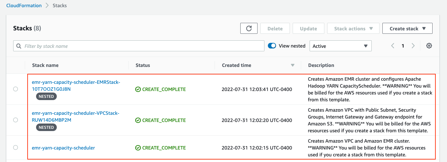
  • On the AWS CloudFormation console, check for the successful deployment of the following stacks.

AWS CloudFormation Stack Deployment

  • On the Amazon EMR console, check for the successful creation of the emr-cluster-capacity-scheduler cluster.
  • Choose the cluster and on the Configurations tab, review the properties under the capacity-scheduler and yarn-site classification labels.

AWS EMR Configurations

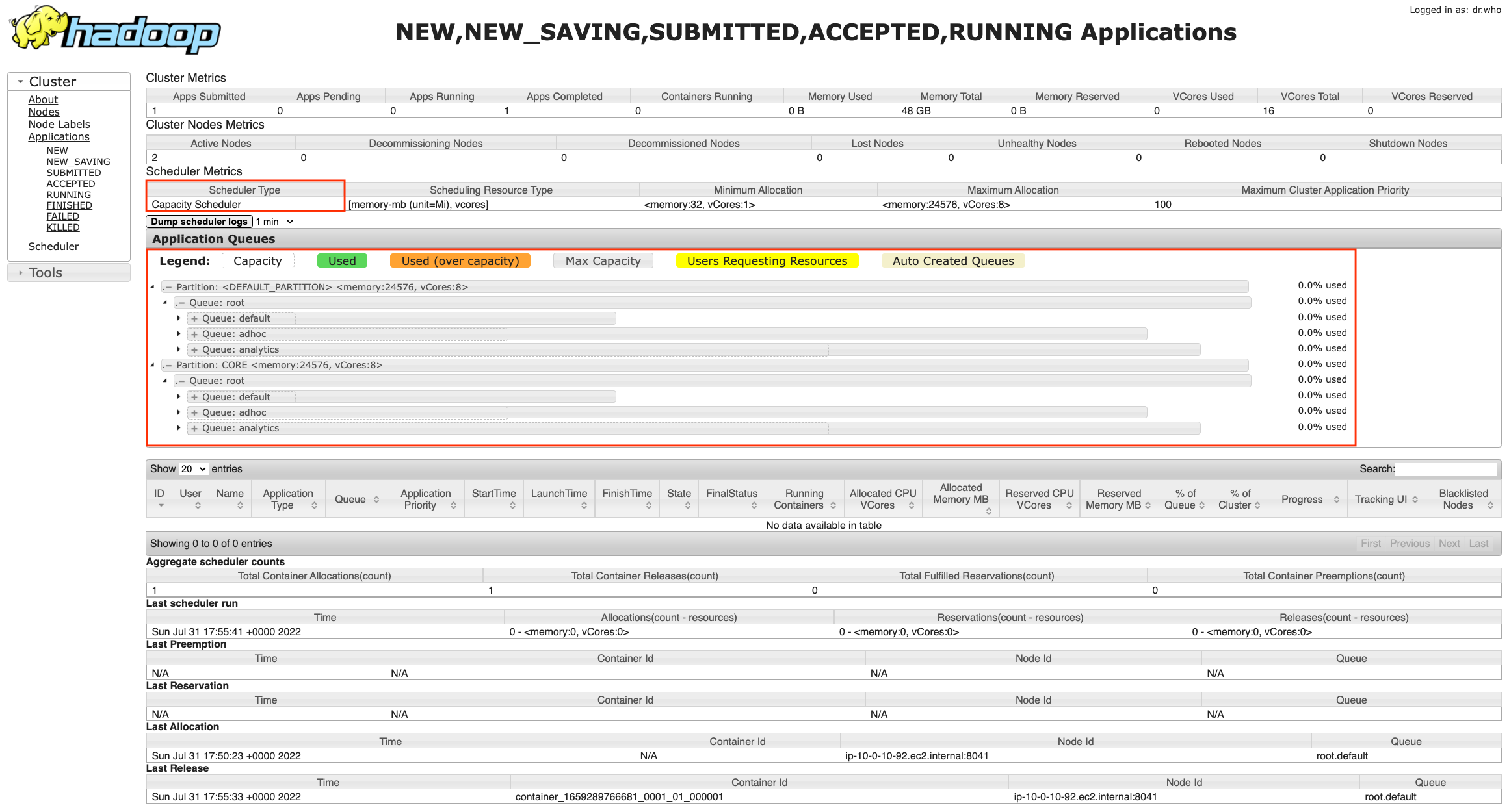
  • Access the Hadoop YARN resource manager UI on the emr-cluster-capacity-scheduler cluster to review the CapacityScheduler setup. For instructions on how to access the UI on Amazon EMR, refer to View web interfaces hosted on Amazon EMR clusters.

Apache Hadoop YARN UI

  • SSH into the emr-cluster-capacity-scheduler cluster and review the following files.For instructions on how to SSH into the EMR primary node, refer to Connect to the master node using SSH.
    • /etc/hadoop/conf/yarn-site.xml
    • /etc/hadoop/conf/capacity-scheduler.xml

All the parameters set using the yarn-site and capacity-scheduler classifiers are reflected in these files. If an admin wants to update CapacityScheduler configs, they can directly update capacity-scheduler.xml and run the following command to apply the changes without interrupting any running jobs and services:

yarn rmadmin -resfreshQueues

Changes to yarn-site.xml require the ResourceManager service to be restarted, which interrupts the running jobs. As a best practice, refrain from manual modifications and use version control for change management.

The CloudFormation template adds a bootstrap action to create test users (user1, user2, user3, user4, user5 and user6) on all the nodes and adds a step script to create HDFS directories for the test users.

Users can SSH into the  primary node, sudo as different users and submit Spark jobs to verify the job submission and CapacityScheduler behavior:

[hadoop@ip-xx-x-xx-xxx ~]$ sudo su - user1
[user1@ip-xx-x-xx-xxx ~]$ spark-submit --master yarn --deploy-mode cluster \
--class org.apache.spark.examples.SparkPi /usr/lib/spark/examples/jars/spark-examples.jar

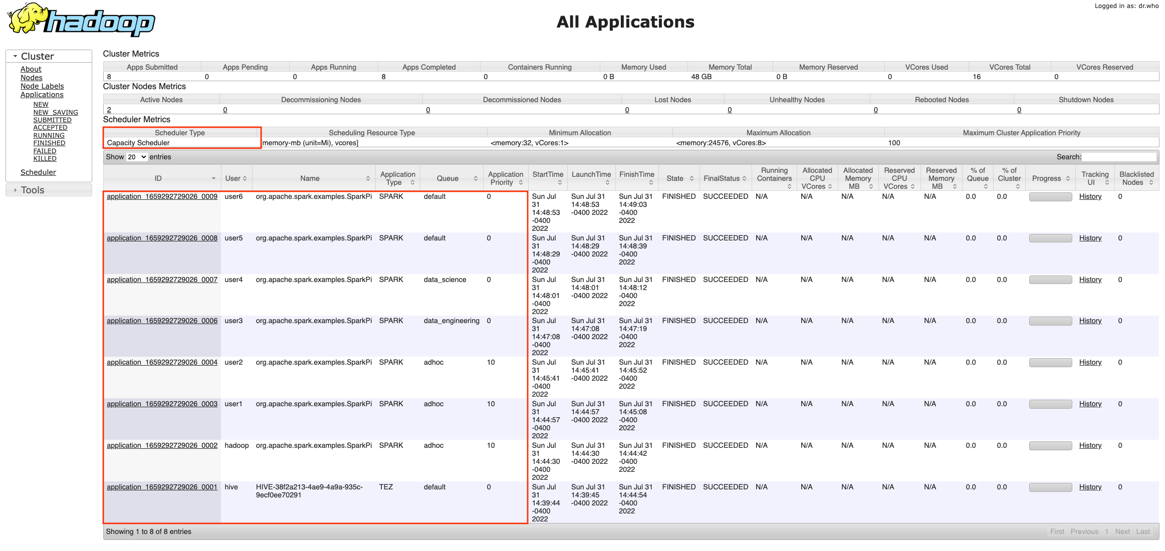
You can validate the results from the resource manager web UI.

Apache Hadoop YARN Jobs List

Clean up

To avoid incurring future charges, delete the resources you created.

  • Delete the CloudFormation stack:
    aws cloudformation delete-stack --stack-name emr-yarn-capacity-scheduler

  • Delete the S3 bucket:
    aws s3 rb s3://emr-yarn-capacity-scheduler-<AWS_ACCOUNT_ID>-<AWS_REGION> --force

The command deletes the bucket and all files underneath it. The files may not be recoverable after deletion.

Conclusion

In this post, we discussed Apache Hadoop YARN and its various components. We discussed the types of schedulers available in Hadoop YARN. We dived deep in to the specifics of Hadoop YARN CapacityScheduler and the use of Dominant Resource Fairness to efficiently allocate resources to submitted jobs. We also showcased how to implement the discussed concepts using AWS CloudFormation.

We encourage you to use this post as a starting point to implement CapacityScheduler on Amazon EMR (on Amazon EC2) and customize the solution to meet your specific data platform goals.


About the authors

Suvojit Dasgupta is a Sr. Lakehouse Architect at Amazon Web Services. He works with customers to design and build data solutions on AWS.

Bharat Gamini is a Data Architect focused on big data and analytics at Amazon Web Services. He helps customers architect and build highly scalable, robust, and secure cloud-based analytical solutions on AWS.