Tag Archives: Apache Spark

Deploy Apache YuniKorn batch scheduler for Amazon EMR on EKS

Post Syndicated from Suvojit Dasgupta original https://aws.amazon.com/blogs/big-data/deploy-apache-yunikorn-batch-scheduler-for-amazon-emr-on-eks/

As organizations successfully grow their Apache Spark workloads on Amazon EMR on EKS, they may seek to optimize resource scheduling to further enhance cluster utilization, minimize job queuing, and maximize performance. Although Kubernetes’ default scheduler, kube-scheduler, works well for most containerized applications, it lacks feature sets capable of managing complex big data workloads with specific requirements such as gang scheduling, resource quotas, job priorities, multi-tenancy, and hierarchical queue management. This limitation can result in inefficient resource utilization, longer job completion times, and increased operational costs for organizations running large-scale data processing workloads.

Apache YuniKorn addresses these limitations by providing a custom resource scheduler specifically designed for big data and machine learning (ML) workloads running on Kubernetes. Unlike kube-scheduler, YuniKorn offers features such as gang scheduling, making sure all containers of a Spark application start together, resource fairness amongst multiple tenants, priority and preemption capabilities, and queue management with hierarchical resource allocation. For data engineering and platform teams managing large-scale Spark workloads on Amazon EMR on EKS, YuniKorn can improve resource utilization rates, reduce job completion times, and provide improved resource allocation for multi-tenant clusters. This is particularly valuable for organizations running mixed workloads with varying resource requirements, strict SLA requirements, or complex resource sharing policies across different teams and applications.

This post explores Kubernetes scheduling fundamentals, examines the limitations of the default kube-scheduler for batch workloads, and demonstrates how YuniKorn addresses these challenges. We discuss how to deploy YuniKorn as a custom scheduler for Amazon EMR on EKS, its integration with job submissions, how to configure queues and placement rules, and how to establish resource quotas. We also show these features in action through practical Spark job examples.

Understanding Kubernetes scheduling and the need for YuniKorn

In this section, we dive into the details of Kubernetes scheduling and the need for YuniKorn.

How Kubernetes scheduling works

Kubernetes scheduling is the process of assigning pods to nodes within a cluster while considering resource requirements, scheduling constraints, and isolation constraints. The scheduler evaluates each pod individually against all schedulable worker nodes, considering multiple factors, including resource requirements such as CPU, memory and I/O requests, node affinity preferences for specific node characteristics, inter-pod affinity and anti-affinity rules that determine whether the pods should be distributed across multiple worker nodes or require colocation, taints and tolerations that dictate scheduling constraints, and Quality of Service classifications that influence scheduling priority.

The scheduling process operates through a two-phase approach. During the filtering phase, the scheduler identifies all worker nodes that could potentially host the pod by eliminating those that don’t meet the basic requirements. The scoring phase then ranks all feasible worker nodes using scoring algorithms to determine the optimal placement, ultimately selecting the highest-scoring node for pod assignment.

Default implementation of kube-scheduler

kube-scheduler serves as the Kubernetes default scheduler. This scheduler operates on a pod-by-pod basis, treating each scheduling decision as an independent operation without consideration for the broader application context.When kube-scheduler processes scheduling requests, it follows a continuous workflow. The API server is monitored for newly created pods awaiting node assignment, applies filtering logic to eliminate unsuitable worker nodes, executes its scoring algorithm to rank the remaining candidates, binds the selected pod to the optimal node, and repeats the process with the next unscheduled pod in the queue.This individual pod scheduling approach works well for microservices and web applications where each pod has fewer interdependencies. However, this design creates significant challenges when applied to distributed big data frameworks like Spark that require coordinated scheduling of multiple interdependent pods.

Challenges using kube-scheduler for batch jobs

Batch processing workloads, particularly those built on Spark, present different scheduling requirements that expose limitations in kube-scheduler algorithm. Such applications consist of multiple pods that must operate as a cohesive unit, yet kube-scheduler lacks the application-level awareness necessary to handle coordinated scheduling requirements.

Gang scheduling challenges

The most significant challenge emerges from the need for gang scheduling, where all components of a distributed application must be scheduled simultaneously. A typical Spark application requires a driver pod and multiple executor pods running in parallel to function correctly. Without YuniKorn, kube-scheduler first schedules the driver pod without knowing the total amount of resources that the driver and executors will need together. When the driver pod starts running, it attempts to spin up the required executor pods but might fail to find sufficient resources in the cluster. This sequential approach can result in the driver being scheduled successfully while some or all executor pods remain in a pending state due to insufficient cluster capacity.This partial scheduling creates a problematic scenario where the application consumes cluster resources but can’t execute meaningful work. The partially scheduled application will hold onto allocated resources indefinitely while waiting for the missing components, preventing other applications from utilizing those resources and resulting in a deadlock situation.

Resource fragmentation issues

Resource fragmentation represents another critical issue that emerges from individual pod scheduling. When multiple batch applications compete for cluster resources, the lack of coordinated scheduling leads to scenarios where sufficient total resources exist for a given application, but they become fragmented across multiple incomplete applications. This fragmentation prevents efficient resource utilization and can leave applications in perpetual pending states.

The absence of hierarchical queue management further compounds these challenges. kube-scheduler provides limited support for hierarchical resource allocation, making it difficult to implement fair sharing policies across different tenants. Organizations can’t easily establish resource quotas that guarantee minimum allocations while setting maximum limits, nor can they implement preemption policies that allow higher-priority jobs to reclaim resources from lower-priority workloads.

The Need for YuniKorn

YuniKorn addresses these batch scheduling limitations through a set of features designed for distributed computing workloads. Unlike the pod-centric approach of kube-scheduler, YuniKorn operates with application-level awareness, understanding the relationships between different components of distributed applications and making scheduling decisions accordingly. The features are as follows:

  • Gang scheduling for atomic application deployment – Gang scheduling represents YuniKorn’s advantage for batch workloads. This capability makes sure pods belonging to an application are scheduled atomically—either all components receive node assignments, or none are scheduled until sufficient resources become available. YuniKorn’s all-or-nothing approach to scheduling minimizes resource deadlocks and partial application failures that impact kube-scheduler based deployments, resulting in more predictable job execution and higher completion rates.
  • Hierarchical queue management and resource organization – YuniKorn’s queue management system provides the hierarchical resource organization that enterprise batch processing environments require. Organizations can establish multi-level queue structures that mirror their organizational hierarchy, implementing resource quotas at each level to facilitate fair resource distribution. The scheduler supports guaranteed resource allocations that provide minimum resource commitments and maximum limits that prevent a single queue from monopolizing cluster resources.
  • Dynamic resource preemption based on priority – The preemption capabilities built into YuniKorn enable dynamic resource reallocation based on job priorities and queue policies. When higher-priority applications require resources currently allocated to lower-priority workloads, YuniKorn can gracefully stop lower-priority pods and reallocate their resources, making sure critical jobs receive the resources they need without manual intervention.
  • Intelligent resource pooling and fair share distribution – Resource pooling and fair share scheduling further enhance YuniKorn’s effectiveness for batch workloads. Rather than treating each scheduling decision in isolation, YuniKorn considers the broader resource allocation landscape, implementing fair-share algorithms that facilitate equitable resource distribution across different applications and users while maximizing overall cluster utilization.

These features add to the existing capabilities of Amazon EMR on EKS by establishing an enhanced environment in which the unique requirements of distributed computing workloads are satisfied.

Solution overview

Consider HomeMax, a fictitious company operating a shared Amazon EMR on EKS cluster where three teams regularly submit Spark jobs with distinct characteristics and priorities:

  • Analytics team – Runs time-sensitive customer analysis jobs requiring immediate processing for business decisions
  • Marketing team – Executes large overnight batch jobs for campaign optimization with predictable resource patterns
  • Data science team – Runs experimental workloads with varying resource needs throughout the day for model development and research

Without proper resource scheduling, these teams face common challenges: resource contention, job failures due to partial scheduling, and inability to guarantee SLAs for critical workloads.For our YuniKorn demonstration, we configured an Amazon EMR on EKS cluster with the following specifications:

  • Amazon EKS cluster: Four worker nodes using m5.2xlarge Amazon Elastic Compute Cloud (Amazon EC2) instances
  • Per-node resources: 8 vCPUs, 32 GiB memory
  • Total cluster capacity: 32 vCPU cores and 128 GiB memory
  • Available for Spark: Approximately 30 vCPUs and approximately 120 GiB memory (after system overhead)
  • Kubernetes version: 1.30+ (required for YuniKorn 1.6.x compatibility)

The following code shows the node group configuration:

# EKS Node Group specification
NodeGroup:
  InstanceTypes:
    - m5.2xlarge
  ScalingConfig:
    MinSize: 4
    DesiredSize: 4
    MaxSize: 4
  DiskSize: 20
  AmiType: AL2023_x86_64_STANDARD

We intentionally use a fixed-capacity cluster to provide a controlled environment that showcases YuniKorn’s scheduling capabilities with consistent, predictable resources. This approach makes resource contention scenarios more apparent and demonstrates how YuniKorn resolves them.

Amazon EMR on EKS offers robust scaling capabilities through Karpenter. The principles demonstrated in this fixed environment apply equally to dynamic environments, where YuniKorn’s capabilities complement the scaling features of Amazon EMR on EKS to optimize resource utilization during peak demand periods or when scaling limits are reached.

The following diagram shows the high-level architecture of the YuniKorn scheduler running on Amazon EMR on EKS. This solution also includes a secure bastion host not shown in the architecture diagram that provides access to the EKS cluster via AWS Systems Manager (SSM) Session Manager. The bastion host is deployed in a private subnet with all necessary tools pre-installed with proper permissions for seamless cluster interaction.

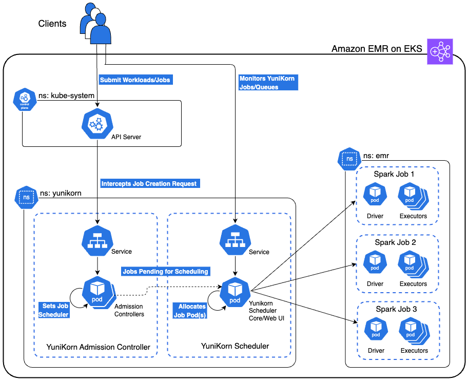
In the following sections, we explore YuniKorn’s queue architecture optimized for this use case. We examine various demonstration scenarios, including gang scheduling, queue-based resource management, priority-based preemption, and fair share distribution. We walk through the process of deploying an Amazon EMR on EKS cluster, implementing the YuniKorn scheduler, configuring the specified queues, and submitting Spark jobs to showcase these scenarios.

YuniKorn integration on Amazon EMR on EKS

The integration involves three key components working together: the Amazon EMR on EKS virtual cluster configuration, YuniKorn’s admission webhook system, and job-level queue annotations.

Namespace and virtual cluster foundation

The integration begins with a dedicated Kubernetes namespace where your Amazon EMR on EKS jobs will run. In our demonstration, we use the emr namespace, created as a standard Kubernetes namespace:

apiVersion: v1
kind: Namespace
metadata:
  name: emr

The Amazon EMR on EKS virtual cluster is configured to deploy all jobs within this specific namespace. When creating the virtual cluster, you specify the namespace in the container provider configuration:

aws emr-containers create-virtual-cluster \
    --name "emr-on-eks-cluster-v" \
    --container-provider "{
        \"id\": \"my-eks-cluster\",
        \"type\": \"EKS\",
        \"info\": {
            \"eksInfo\": {
                \"namespace\": \"emr\"
            }
        }
    }"

This configuration makes sure all jobs submitted to this virtual cluster will be deployed in the emr namespace, establishing the foundation for YuniKorn integration.

The YuniKorn interception mechanism

When YuniKorn is installed using Helm, it automatically registers a MutatingAdmissionWebhook with the Kubernetes API server. This webhook acts as an interceptor that monitors pod creation events in your designated namespace. The webhook registration tells Kubernetes to call YuniKorn whenever pods are created in the emr namespace:

# YuniKorn registers this webhook configuration
apiVersion: admissionregistration.k8s.io/v1
kind: MutatingAdmissionWebhook
rules:
- operations: ["CREATE"]
  resources: ["pods"]
  namespaces: ["emr"]  # Intercepts pods in EMR namespace

This webhook is triggered by any pod creation in the emr namespace, not specifically by YuniKorn annotations. However, the webhook’s logic only modifies pods that contain YuniKorn queue annotations, leaving other pods unchanged.

End-to-end job flow

When you submit a Spark job through the Spark Operator, the following sequence occurs:

  1. Your Spark job includes YuniKorn queue annotations on both driver and executor pods:
driver:
  annotations:
    yunikorn.apache.org/queue: "root.analytics-queue"
executor:
  annotations:
    yunikorn.apache.org/queue: "root.analytics-queue"
  1. The Spark Operator processes your SparkApplication and creates individual Kubernetes pods for the driver and executors. These pods inherit the YuniKorn annotations from your job template.
  2. When the Spark Operator attempts to create pods in the emr namespace, Kubernetes calls YuniKorn’s admission webhook. The webhook examines each pod and performs the following actions:
    1. Detects pods with yunikorn.apache.org/queue annotations.
    2. Adds schedulerName: yunikorn to those pods.
    3. Leaves pods without YuniKorn annotations unchanged.

This interception means you don’t need to manually specify schedulerName: yunikorn in your Spark jobs—YuniKorn claims the pods transparently based on the presence of queue annotations.

  1. The YuniKorn scheduler receives the scheduling requests and applies the queue placement rules configured in the YuniKorn ConfigMap:
placementrules:
  - name: provided    # Uses the annotation value
    create: false.    # Doesn’t create the queue if not present
  - name: fixed       # Fallback to root.default queue
    value: root.default

The provided rule reads the yunikorn.apache.org/queue annotation and places the job in the specified queue (for example, root.analytics-queue). YuniKorn then applies gang scheduling logic, holding all pods until sufficient resources are available for the entire application, preventing the partial scheduling issues that come with kube-scheduler.

  1. After YuniKorn determines that all pods can be scheduled according to the queue’s resource guarantees and limits, it schedules all driver and executor pods. The Spark job begins execution with the guaranteed resource allocation defined in the queue configuration.

The combination of namespace-based virtual cluster configuration, admission webhook interception, and annotation-driven queue placement creates an integration that transforms Amazon EMR on EKS job scheduling without disrupting existing workflows.

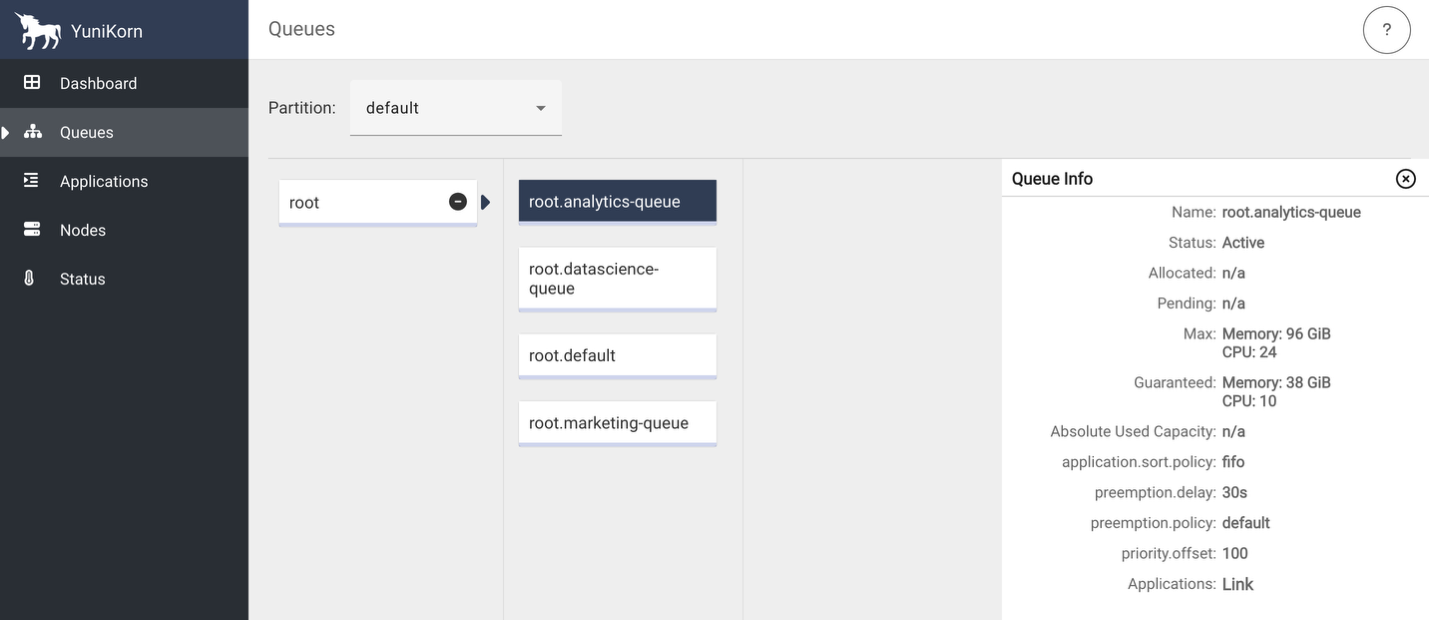
YuniKorn queue architecture

To demonstrate the various YuniKorn features described in the next section, we configured three job-specific queues and a default queue representing our enterprise teams with carefully balanced resource allocations:

# Analytics Queue - Time-sensitive workloads
analytics-queue:
  guaranteed: 10 vCPUs, 38GB memory (30% of cluster)
  max: 24 vCPUs, 96GB memory (80% burst capacity)
  priority: 100 (highest)
  policy: FIFO (predictable scheduling)
# Marketing Queue - Large batch jobs
marketing-queue:
  guaranteed: 8 vCPUs, 32GB memory (25% of cluster)
  max: 24 vCPUs, 96GB memory (80% burst capacity)
  priority: 75 (medium)
  policy: Fair Share (balanced resource distribution)
# Data Science Queue - Experimental workloads
datascience-queue:
  guaranteed: 6 vCPUs, 26GB memory (20% of cluster)
  max: 24 vCPUs, 96GB memory (80% burst capacity)
  priority: 50 (lower)
  policy: Fair Share (experimental workload balancing)
# Default Queue - Fallback for unmatched jobs
default:
  guaranteed: 6 vCPUs, 26GB memory (20% of cluster)
  max: 24 vCPUs, 96GB memory (80% burst capacity)
  priority: 25 (lowest)
  policy: FIFO (predictable job submission)

Demonstration scenarios

This section outlines key YuniKorn scheduling capabilities and their corresponding Spark job submissions. These scenarios demonstrate guaranteed resource allocation and burst capacity usage. Guaranteed resources represent minimum allocations that queues can always access, but jobs might exceed these allocations when additional cluster capacity is available. The marketing-job specifically demonstrates burst capacity usage beyond its guaranteed allocation.

  • Gang scheduling – In this scenario, we submit analytics-job.py (analytics-queue, 9 total cores) and marketing-job.py (marketing-queue, 17 total cores) simultaneously. YuniKorn makes sure all pods for each job are scheduled atomically, preventing partial resource allocation that could cause job failures in our resource-constrained cluster.
  • Queue-based resource management – We run all three jobs concurrently to observe guaranteed resource allocation. YuniKorn distributes remaining capacity proportionally based on queue weights and maximum limits.
    • analytics-job.py (analytics-queue) receives guaranteed 10 vCPUs and 38 GB memory.
    • marketing-job.py (marketing-queue) receives guaranteed 8 vCPUs and 32 GB memory.
    • datascience-job.py (datascience-queue) receives guaranteed 6 vCPUs and 26 GB memory.
  • Priority-based preemption – We start datascience-job.py (datascience-queue, priority 25) and marketing-job.py (marketing-queue, priority 50) consuming cluster resources, then submit high-priority analytics-job.py (analytics-queue, priority 100). YuniKorn preempts lower-priority jobs to make sure the time-sensitive analytics workload gets its guaranteed resources, maintaining SLA compliance.
  • Fair share distribution – We submit multiple jobs to each queue when all queues have available capacity. YuniKorn applies configured fair share policies within queues—the analytics queue uses First In, First Out (FIFO) method for predictable scheduling, and the marketing and data science queues use fair sharing method for balanced resource distribution.

Source code

You can find the codebase in the AWS Samples GitHub repository.

Prerequisites

Before you deploy this solution, make sure the following prerequisites are in place:

Set up the solution infrastructure

Complete the following steps to set up the infrastructure:

  1. Clone the repository to your local machine and set the two environment variables. Replace <AWS_REGION> with the AWS Region where you want to deploy these resources.
git clone https://github.com/aws-samples/sample-emr-eks-yunikorn-scheduler.git
cd sample-emr-eks-yunikorn-scheduler
export REPO_DIR=$(pwd)
export AWS_REGION=<AWS_REGION>
  1. Execute the following script to create the infrastructure:
cd $REPO_DIR/infrastructure
./setup-infra.sh
  1. To verify successful infrastructure deployment, open the AWS CloudFormation console, choose your stack, and check the Events, Resources, and Outputs tabs for completion status, details, and list of resources created.

Deploy YuniKorn on Amazon EMR on EKS

Run the following script to deploy the Yunikorn helm chart and update the configmap with the queues and placement rules:

cd $REPO_DIR/yunikorn/
./setup-yunikorn.sh

Establish EKS cluster connectivity

Complete the following steps to establish secure connectivity to your private EKS cluster:

  1. Execute the following script in a new terminal window. This script establishes port forwarding through the bastion host to make your private EKS cluster accessible from your local machine. Keep this terminal window open and running throughout your work session. The script maintains the connection to your EKS cluster.
export REPO_DIR=$(pwd)
export AWS_REGION=<AWS_REGION>
cd $REPO_DIR/port-forward
./eks-connect.sh --start
  1. Test kubectl connectivity in the main terminal window to verify that you can successfully communicate with the EKS cluster. You should see the EKS worker nodes listed, confirming that the port forwarding is working correctly.

kubectl get nodes

Verify successful YuniKorn deployment

Complete the following steps to verify a successful deployment:

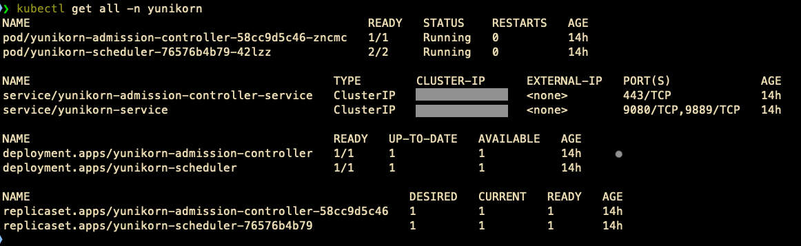
  1. List all Kubernetes objects in the yunikorn namespace:

kubectl get all -n yunikorn

You will see details like the following screenshot.

  1. Check the YuniKorn scheduler logs for configuration loading and look for queue configuration messages:
kubectl logs -n yunikorn deployment/yunikorn-scheduler --tail=50
kubectl logs -n yunikorn deployment/yunikorn-scheduler | grep -i queue
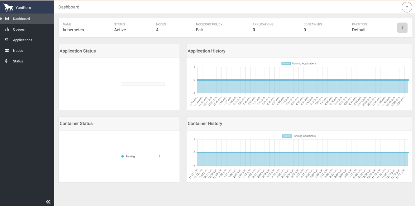
  1. Access the YuniKorn web UI by navigating to http://127.0.0.1:9889 in your browser. Port 9889 is the default port for the YuniKorn web UI.
# macOS
open http://127.0.0.1:9889
# Linux
xdg-open http://127.0.0.1:9889
# Windows
start http://127.0.0.1:9889

The following screenshots show the YuniKorn web UI with queues but no running applications.

Run Spark jobs with YuniKorn on Amazon EMR on EKS

Complete the following steps to run Spark jobs with YuniKorn on Amazon EMR on EKS:

  1. Execute the following script to set up the Spark jobs environment. The script uploads PySpark scripts to Amazon Simple Storage Service (Amazon S3) bucket locations and creates ready-to-use YAML files from templates.
cd $REPO_DIR/spark-jobs
./setup-spark-jobs.sh
  1. Submit analytics, marketing, and data science Spark jobs using the following commands. YuniKorn will place the jobs in their respective queues and allocate resources to execution. Refer to Using YuniKorn as a custom scheduler for Apache Spark on Amazon EMR on EKS for supported job submission methods with YuniKorn as a custom scheduler.
kubectl apply -f spark-operator/analytics-job.yaml
kubectl apply -f spark-operator/marketing-job.yaml
kubectl apply -f spark-operator/datascience-job.yaml
  1. Review the previous section describing different demonstration scenarios and submit the Spark jobs using various combinations to see YuniKorn scheduler’s capabilities in action. We encourage you to adjust the cores, instances, and memory parameters and explore the scheduler’s behavior by executing the jobs. We also encourage you to modify the queues’ guaranteed and max capacities in the file yunikorn/queue-config-provided.yaml, apply the changes, and submit jobs to further understand Yunikorn scheduler behavior under various circumstances.

Clean up

To avoid incurring future charges, complete the following steps to delete the resources you created:

  1. Stop the port forwarding sessions:
cd $REPO_DIR/port-forwarding
./eks-connect.sh --stop
  1. Remove all created AWS resources:
cd $REPO_DIR
./cleanup.sh

Conclusion

YuniKorn addresses the scheduling limitations of default kube-scheduler while running Spark workloads on Amazon EMR on EKS through gang scheduling, intelligent queue management, and priority-based resource allocation. This post showed how YuniKorn’s queue system enables better resource utilization, prevents job failure due to poor allocation of resources, and supports multi-tenant environments.

To get started with YuniKorn on Amazon EMR on EKS, explore the Apache YuniKorn documentation for implementation guides, review Amazon EMR on EKS best practices for optimization strategies, and engage with the YuniKorn community for ongoing support.


About the authors

Suvojit Dasgupta is a Principal Data Architect at Amazon Web Services. He leads a team of skilled engineers in designing and building scalable data solutions for diverse customers. He specializes in developing and implementing innovative data architectures to address complex business challenges.

Peter Manastyrny is a Senior Product Manager at AWS Analytics. He leads Amazon EMR on EKS, a product that makes it straightforward and efficient to run open-source data analytics frameworks such as Spark on Amazon EKS.

Matt Poland is a Senior Cloud Infrastructure Architect at Amazon Web Services. He is passionate about solving complex problems and delivering well-structured solutions for diverse customers. His expertise spans across a range of cloud technologies, providing scalable and reliable infrastructure tailored to each project’s unique challenges.

Gregory Fina is a Principal Startup Solutions Architect for Generative AI at Amazon Web Services, where he empowers startups to accelerate innovation through cloud adoption. He specializes in application modernization, with a strong focus on serverless architectures, containers, and scalable data storage solutions. He is passionate about using generative AI tools to orchestrate and optimize large-scale Kubernetes deployments, as well as advancing GitOps and DevOps practices for high-velocity teams. Outside of his customer-facing role, Greg actively contributes to open source projects, especially those related to Backstage.

Build a centralized observability platform for Apache Spark on Amazon EMR on EKS using external Spark History Server

Post Syndicated from Sri Potluri original https://aws.amazon.com/blogs/big-data/build-a-centralized-observability-platform-for-apache-spark-on-amazon-emr-on-eks-using-external-spark-history-server/

Monitoring and troubleshooting Apache Spark applications become increasingly complex as companies scale their data analytics workloads. As data processing requirements grow, enterprises deploy these applications across multiple Amazon EMR on EKS clusters to handle diverse workloads efficiently. However, this approach creates a challenge in maintaining comprehensive visibility into Spark applications running across these separate clusters. Data engineers and platform teams need a unified view to effectively monitor and optimize their Spark applications.

Although Spark provides powerful built-in monitoring capabilities through Spark History Server (SHS), implementing a scalable and secure observability solution across multiple clusters requires careful architectural considerations. Organizations need a solution that not only consolidates Spark application metrics but extends its features by adding other performance monitoring and troubleshooting packages while providing secure access to these insights and maintaining operational efficiency.

This post demonstrates how to build a centralized observability platform using SHS for Spark applications running on EMR on EKS. We showcase how to enhance SHS with performance monitoring tools, with a pattern applicable to many monitoring solutions such as SparkMeasure and DataFlint. In this post, we use DataFlint as an example to demonstrate how you can integrate additional monitoring features. We explain how to collect Spark events from multiple EMR on EKS clusters into a central Amazon Simple Storage Service (Amazon S3) bucket; deploy SHS on a dedicated Amazon Elastic Kubernetes Service (Amazon EKS) cluster; and configure secure access using AWS Load Balancer Controller, AWS Private Certificate Authority, Amazon Route 53, and AWS Client VPN. This solution provides teams with a single, secure interface to monitor, analyze, and troubleshoot Spark applications across multiple clusters.

Overview of solution

Consider DataCorp Analytics, a data-driven enterprise running multiple business units with diverse Spark workloads. Their Financial Analytics team processes time-sensitive trading data requiring strict processing times and dedicated resources, and their Marketing Analytics team handles customer behavior data with flexible requirements, requiring multiple EMR on EKS clusters to accommodate these distinct workload patterns. As their Spark applications grow in number and complexity across these clusters, data and platform engineers struggle to maintain comprehensive visibility while maintaining secure access to monitoring tools.

This scenario presents an ideal use case for implementing a centralized observability platform using SHS and DataFlint. The solution deploys SHS on a dedicated EKS cluster, configured to read events from multiple EMR on EKS clusters through a centralized S3 bucket. Access is secured through Load Balancer Controller, AWS Private CA, Route 53, and Client VPN, and DataFlint enhances the monitoring capabilities with additional insights and visualizations. The following architecture diagram illustrates the components and their interactions.

Architecture diagram

The solution workflow is as follows:

  1. Spark applications on EMR on EKS use a custom EMR Docker image that includes DataFlint JARs for enhanced metrics collection. These applications generate detailed event logs containing execution metrics, performance data, and DataFlint-specific insights. The logs are written to a centralized Amazon S3 location through the following configuration (note especially the configurationOverrides section). For additional information, explore the StartJobRun guide to learn how to run Spark jobs and review the StartJobRun API reference.
{
  "name": "${SPARK_JOB_NAME}", 
  "virtualClusterId": "${VIRTUAL_CLUSTER_ID}",  
  "executionRoleArn": "${IAM_ROLE_ARN_FOR_JOB_EXECUTION}",
  "releaseLabel": "emr-7.2.0-latest", 
  "jobDriver": {
    "sparkSubmitJobDriver": {
      "entryPoint": "s3://${S3_BUCKET_NAME}/app/${SPARK_APP_FILE}",
      "entryPointArguments": [
        "--input-path",
        "s3://${S3_BUCKET_NAME}/data/input",
        "--output-path",
        "s3://${S3_BUCKET_NAME}/data/output"
      ],
       "sparkSubmitParameters": "--conf spark.driver.cores=1 --conf spark.driver.memory=4G --conf spark.kubernetes.driver.limit.cores=1200m --conf spark.executor.cores=2  --conf spark.executor.instances=3  --conf spark.executor.memory=4G"
    }
  }, 
  "configurationOverrides": {
    "applicationConfiguration": [
      {
        "classification": "spark-defaults", 
        "properties": {
          "spark.driver.memory":"2G",
          "spark.kubernetes.container.image": "${AWS_ACCOUNT_ID}.dkr.ecr.${AWS_REGION}.amazonaws.com/${EMR_REPO_NAME}:${EMR_IMAGE_TAG}",
          "spark.app.name": "${SPARK_JOB_NAME}"
          "spark.eventLog.enabled": "true",
          "spark.eventLog.dir": "s3://${S3_BUCKET_NAME}/spark-events/"
         }
      }
    ], 
    "monitoringConfiguration": {
      "persistentAppUI": "ENABLED",
      "s3MonitoringConfiguration": {
        "logUri": "s3://${S3_BUCKET_NAME}/spark-events/"
      }
    }
  }
}
  1. A dedicated SHS deployed on Amazon EKS reads these centralized logs. The Amazon S3 location is configured in the SHS to read from the central Amazon S3 location through the following code:
env:
  - name: SPARK_HISTORY_OPTS
    value: "-Dspark.history.fs.logDirectory=s3a://${S3_BUCKET}/spark-events/"
  1. We configure Load Balancer Controller, AWS Private CA, a Route 53 hosted zone, and Client VPN to securely access the SHS UI using a web browser.
  2. Finally, users can access the SHS web interface at https://spark-history-server.example.internal/.

You can find the code base in the AWS Samples GitHub repository.

Prerequisites

Before you deploy this solution, make sure the following prerequisites are in place:

Set up a common infrastructure

Complete the following steps to set up the infrastructure:

  1. Clone the repository to your local machine and set the two environment variables. Replace <AWS_REGION> with the AWS Region where you want to deploy these resources.
git clone [email protected]:aws-samples/sample-centralized-spark-history-server-emr-on-eks.git
cd sample-centralized-spark-history-server-emr-on-eks
export REPO_DIR=$(pwd)
export AWS_REGION=<AWS_REGION>
  1. Execute the following script to create the common infrastructure. The script creates a secure virtual private cloud (VPC) networking environment with public and private subnets and an encrypted S3 bucket to store Spark application logs.
cd ${REPO_DIR}/infra
./deploy_infra.sh
  1. To verify successful infrastructure deployment, open the AWS CloudFormation console, choose your stack, and check the Events, Resources, and Outputs tabs for completion status, details, and list of resources created.

Set up EMR on EKS clusters

This section covers building a custom EMR on EKS Docker image with DataFlint integration, launching two EMR on EKS clusters (datascience-cluster-v and analytics-cluster-v), and configuring the clusters for job submission. Additionally, we set up the necessary IAM roles for service accounts (IRSA) to enable Spark jobs to write events to the centralized S3 bucket. Complete the following steps:

  1. Deploy two EMR on EKS clusters:
cd ${REPO_DIR}/emr-on-eks
./deploy_emr_on_eks.sh
  1. To verify successful creation of the EMR on EKS clusters using the AWS CLI, execute the following command:
aws emr-containers list-virtual-clusters \
    --query "virtualClusters[?state=='RUNNING']"
  1. Execute the following command for the datascience-cluster-v and analytics-cluster-v clusters to verify their respective states, container provider information, and associated EKS cluster details. Replace <VIRTUAL-CLUSTER-ID> with the ID of each cluster obtained from the list-virtual-clusters output.
aws emr-containers describe-virtual-cluster \
    --id <VIRTUAL-CLUSTER-ID>

Configure and execute Spark jobs on EMR on EKS clusters

Complete the following steps to configure and execute Spark jobs on the EMR on EKS clusters:

  1. Generate custom EMR on EKS image and StartJobRun request JSON files to run Spark jobs:
cd ${REPO_DIR}/jobs
./configure_jobs.sh

The script performs the following tasks:

  • Prepares the environment by uploading the sample Spark application spark_history_demo.py to a designated S3 bucket for job execution.
  • Creates a custom Amazon EMR container image by extending the base EMR 7.2.0 image with the DataFlint JAR for additional insights and publishing it to an Amazon Elastic Container Registry (Amazon ECR) repository.
  • Generates cluster-specific StartJobRun request JSON files for datascience-cluster-v and analytics-cluster-v.

Review start-job-run-request-datascience-cluster-v.json and start-job-run-request-analytics-cluster-v.json for additional details.

  1. Execute the following commands to submit Spark jobs on the EMR on EKS virtual clusters:
aws emr-containers start-job-run \
--cli-input-json file://${REPO_DIR}/jobs/start-job-run/start-job-run-request-datascience-cluster-v.json
aws emr-containers start-job-run \
--cli-input-json file://${REPO_DIR}/jobs/start-job-run/start-job-run-request-analytics-cluster-v.json
  1. Verify the successful generation of the logs in the S3 bucket:

aws s3 ls s3://emr-spark-logs-<AWS_ACCOUNT_ID>-<AWS_REGION>/spark-events/

You have successfully set up an EMR on EKS environment, executed Spark jobs, and collected the logs in the centralized S3 bucket. Next, we will deploy SHS, configure its secure access, and visualize the logs using it.

Set up AWS Private CA and create a Route 53 private hosted zone

Use the following code to deploy AWS Private CA and create a Route 53 private hosted zone. This will provide a user-friendly URL to connect to SHS over HTTPS.

cd ${REPO_DIR}/ssl
./deploy_ssl.sh

Set up SHS on Amazon EKS

Complete the following steps to build a Docker image containing SHS with DataFlint, deploy it on an EKS cluster using a Helm chart, and expose it through a Kubernetes service of type LoadBalancer. We use a Spark 3.5.0 base image, which includes SHS by default. However, although this simplifies deployment, it results in a larger image size. For environments where image size is critical, consider building a custom image with just the standalone SHS component instead of using the complete Spark distribution.

  1. Deploy SHS on the spark-history-server EKS cluster:
cd ${REPO_DIR}/shs
./deploy_shs.sh
  1. Verify the deployment by listing the pods and viewing the pod logs:
kubectl get pods --namespace spark-history
kubectl logs <SHS-PODNAME> --namespace spark-history
  1. Review the logs and confirm there are no errors or exceptions.

You have successfully deployed SHS on the spark-history-server EKS cluster, and configured it to read logs from the emr-spark-logs-<AWS_ACCOUNT_ID>-<AWS_REGION> S3 bucket.

Deploy Client VPN and add entry to Route 53 for secure access

Complete the following steps to deploy Client VPN to securely connect your client machine (such as your laptop) to SHS and configure Route 53 to generate a user-friendly URL:

  1. Deploy the Client VPN:
cd ${REPO_DIR}/vpn
./deploy_vpn.sh
  1. Add entry to Route 53:
cd ${REPO_DIR}/dns
./deploy_dns.sh

Add certificates to local trusted stores

Complete the following steps to add the SSL certificate to your operating system’s trusted certificate stores for secure connections:

  1. For macOS users, using Keychain Access (GUI):
    1. Open Keychain Access from Applications, Utilities, choose the System keychain in the navigation pane, and choose File, Import Items.
    2. Browse to and choose ${REPO_DIR}/ssl/certificates/ca-certificate.pem, then choose the imported certificate.
    3. Expand the Trust section and set When using this certificate to Always Trust.
    4. Close and enter your password when prompted and save.
    5. Alternatively, you can execute the following command to include the certificate in Keychain and trust it:
sudo security add-trusted-cert -d -r trustRoot -k /Library/Keychains/System.keychain "${REPO_DIR}/ssl/certificates/ca-certificate.pem"
  1. For Windows users:
    1. Rename ca-certificate.pem to ca-certificate.crt.
    2. Choose (right-click) ca-certificate.crt and choose Install Certificate.
    3. Choose Local Machine (admin rights required).
    4. Select Place all certificates in the following store.
    5. Choose Browse and choose Trusted Root Certification Authorities.
    6. Complete the installation by choosing Next and Finish.

Set up Client VPN on your client machine for secure access

Complete the following steps to install and configure Client VPN on your client machine (such as your laptop) and create a VPN connection to the AWS Cloud:

  1. Download, install, and launch the Client VPN application from the official download page for your operating system.
  2. Create your VPN profile:
    1. Choose File in the menu bar, choose Manage Profiles, and choose Add Profile.
    2. Enter a name for your profile. Example: SparkHistoryServerUI
    3. Browse to ${REPO_DIR}/vpn/client_vpn_certs/client-config.ovpn, choose the certificate file, and choose Add Profile to save your configuration.
  3. Select your newly created profile, choose Connect, and wait for the connection confirmation to establish the VPN connection.

When you’re connected, you will have secure access to the AWS resources in your environment.

VPN connection details

Securely access the SHS URL

Complete the following steps to securely access SHS using a web browser:

  1. Execute the following command to get the SHS URL:

https://spark-history-server.example.internal/

  1. Copy this URL and enter it into your web browser to access the SHS UI.

The following screenshot shows an example of the UI.

Spark History Server job summary page

  1. Choose an App ID to view its detailed execution information and metrics.

Spark History Server job detail page

  1. Choose the DataFlint tab to view detailed application insights and analytics.

DataFlint insights page

DataFlint displays various helpful metrics, including alerts, as shown in the following screenshot.

DataFlint alerts page

Clean up

To avoid incurring future charges from the resources created in this tutorial, clean up your environment after completing the steps. To remove all provisioned resources:

  1. Disconnect from the Client VPN.
  2. Run the cleanup.sh script:
cd ${REPO_DIR}/
./cleanup.sh

Conclusion

In this post, we demonstrated how to build a centralized observability platform for Spark applications using SHS and enhance SHS with performance monitoring tools like DataFlint. The solution aggregates Spark events from multiple EMR on EKS clusters into a unified monitoring interface, providing comprehensive visibility into your Spark applications’ performance and resource utilization. By using a custom EMR image with performance monitoring tool integration, we enhanced the standard Spark metrics to gain deeper insights into application behavior. If your environment uses a mix of EMR on EKS, Amazon EMR on EC2, or Amazon EMR Serverless, you can seamlessly extend this architecture to aggregate the logs from EMR on EC2 and EMR Serverless in a similar way and visualize them using SHS.

Although this solution provides a robust foundation for Spark monitoring, production deployments should consider implementing authentication and authorization. SHS supports custom authentication through javax servlet filters and fine-grained authorization through access control lists (ACLs). We encourage you to explore implementing authentication filters for secure access control, configuring user- and group-based ACLs for view and modify permissions, and setting up group mapping providers for role-based access. For detailed guidance, refer to Spark’s web UI security documentation and SHS security features.

While AWS endeavors to apply best practices for security within this example, each organization has its own policies. Please make sure to use the specific policies of your organization when deploying this solution as a starting point for implementing centralized Spark monitoring in your data processing environment.


About the authors

Sri Potluri is a Cloud Infrastructure Architect at AWS. He is passionate about solving complex problems and delivering well-structured solutions for diverse customers. His expertise spans across a range of cloud technologies, providing scalable and reliable infrastructures tailored to each project’s unique challenges.

Suvojit Dasgupta is a Principal Data Architect at AWS. He leads a team of skilled engineers in designing and building scalable data solutions for AWS customers. He specializes in developing and implementing innovative data architectures to address complex business challenges.

Use Batch Processing Gateway to automate job management in multi-cluster Amazon EMR on EKS environments

Post Syndicated from Umair Nawaz original https://aws.amazon.com/blogs/big-data/use-batch-processing-gateway-to-automate-job-management-in-multi-cluster-amazon-emr-on-eks-environments/

AWS customers often process petabytes of data using Amazon EMR on EKS. In enterprise environments with diverse workloads or varying operational requirements, customers frequently choose a multi-cluster setup due to the following advantages:

  • Better resiliency and no single point of failure – If one cluster fails, other clusters can continue processing critical workloads, maintaining business continuity
  • Better security and isolation – Increased isolation between jobs enhances security and simplifies compliance
  • Better scalability – Distributing workloads across clusters enables horizontal scaling to handle peak demands
  • Performance benefits – Minimizing Kubernetes scheduling delays and network bandwidth contention improves job runtimes
  • Increased flexibility – You can enjoy straightforward experimentation and cost optimization through workload segregation to multiple clusters

However, one of the disadvantages of a multi-cluster setup is that there is no straightforward method to distribute workloads and support effective load balancing across multiple clusters. This post proposes a solution to this challenge by introducing the Batch Processing Gateway (BPG), a centralized gateway that automates job management and routing in multi-cluster environments.

Challenges with multi-cluster environments

In a multi-cluster environment, Spark jobs on Amazon EMR on EKS need to be submitted to different clusters from various clients. This architecture introduces several key challenges:

  • Endpoint management – Clients must maintain and update connections for each target cluster
  • Operational overhead – Managing multiple client connections individually increases the complexity and operational burden
  • Workload distribution – There is no built-in mechanism for job routing across multiple clusters, which impacts configuration, resource allocation, cost transparency, and resilience
  • Resilience and high availability – Without load balancing, the environment lacks fault tolerance and high availability

BPG addresses these challenges by providing a single point of submission for Spark jobs. BPG automates job routing to the appropriate EMR on EKS clusters, providing effective load balancing, simplified endpoint management, and improved resilience. The proposed solution is particularly beneficial for customers with multi-cluster Amazon EMR on EKS setups using the Spark Kubernetes Operator with or without Yunikorn scheduler.

However, although BPG offers significant benefits, it is currently designed to work only with Spark Kubernetes Operator. Additionally, BPG has not been tested with the Volcano scheduler, and the solution is not applicable in environments using native Amazon EMR on EKS APIs.

Solution overview

Martin Fowler describes a gateway as an object that encapsulates access to an external system or resource. In this case, the resource is the EMR on EKS clusters running Spark. A gateway acts as a single point to confront this resource. Any code or connection interacts with the interface of the gateway only. The gateway then translates the incoming API request into the API offered by the resource.

BPG is a gateway specifically designed to provide a seamless interface to Spark on Kubernetes. It’s a REST API service to abstract the underlying Spark on EKS clusters details from users. It runs in its own EKS cluster communicating to Kubernetes API servers of different EKS clusters. Spark users submit an application to BPG through clients, then BPG routes the application to one of the underlying EKS clusters.

The process for submitting Spark jobs using BPG for Amazon EMR on EKS is as follows:

  1. The user submits a job to BPG using a client.
  2. BPG parses the request, translates it into a custom resource definition (CRD), and submits the CRD to an EMR on EKS cluster according to predefined rules.
  3. The Spark Kubernetes Operator interprets the job specification and initiates the job on the cluster.
  4. The Kubernetes scheduler schedules and manages the run of the jobs.

The following figure illustrates the high-level details of BPG. You can read more about BPG in the GitHub README.

Image showing the high-level details of Batch Processing Gateway

The proposed solution involves implementing BPG for multiple underlying EMR on EKS clusters, which effectively resolves the drawbacks discussed earlier. The following diagram illustrates the details of the solution.

Image showing the end to end architecture of of Batch Processing Gateway

Source Code

You can find the code base in the AWS Samples and Batch Processing Gateway GitHub repository.

In the following sections, we walk through the steps to implement the solution.

Prerequisites

Before you deploy this solution, make sure the following prerequisites are in place:

Clone the repositories to your local machine

We assume that all repositories are cloned into the home directory (~/). All relative paths provided are based on this assumption. If you have cloned the repositories to a different location, adjust the paths accordingly.

  1. Clone the BPG on EMR on EKS GitHub repo with the following command:
cd ~/
git clone [email protected]:aws-samples/batch-processing-gateway-on-emr-on-eks.git

The BPG repository is currently under active development. To provide a stable deployment experience consistent with the provided instructions, we have pinned the repository to the stable commit hash aa3e5c8be973bee54ac700ada963667e5913c865.

Before cloning the repository, verify any security updates and adhere to your organization’s security practices.

  1. Clone the BPG GitHub repo with the following command:
git clone [email protected]:apple/batch-processing-gateway.git
cd batch-processing-gateway
git checkout aa3e5c8be973bee54ac700ada963667e5913c865

Create two EMR on EKS clusters

The creation of EMR on EKS clusters is not the primary focus of this post. For comprehensive instructions, refer to Running Spark jobs with the Spark operator. However, for your convenience, we have included the steps for setting up the EMR on EKS virtual clusters named spark-cluster-a-v and spark-cluster-b-v in the GitHub repo. Follow these steps to create the clusters.

After successfully completing the steps, you should have two EMR on EKS virtual clusters named spark-cluster-a-v and spark-cluster-b-v running on the EKS clusters spark-cluster-a and spark-cluster-b, respectively.

To verify the successful creation of the clusters, open the Amazon EMR console and choose Virtual clusters under EMR on EKS in the navigation pane.

Image showing the Amazon EMR on EKS setup

Set up BPG on Amazon EKS

To set up BPG on Amazon EKS, complete the following steps:

  1. Change to the appropriate directory:
cd ~/batch-processing-gateway-on-emr-on-eks/bpg/
  1. Set up the AWS Region:
export AWS_REGION="<AWS_REGION>"
  1. Create a key pair. Make sure you follow your organization’s best practices for key pair management.
aws ec2 create-key-pair \
--region "$AWS_REGION" \
--key-name ekskp \
--key-type ed25519 \
--key-format pem \
--query "KeyMaterial" \
--output text > ekskp.pem
chmod 400 ekskp.pem
ssh-keygen -y -f ekskp.pem > eks_publickey.pem
chmod 400 eks_publickey.pem

Now you’re ready to create the EKS cluster.

By default, eksctl creates an EKS cluster in dedicated virtual private clouds (VPCs). To avoid reaching the default soft limit on the number of VPCs in an account, we use the --vpc-public-subnets parameter to create clusters in an existing VPC. For this post, we use the default VPC for deploying the solution. Modify the following code to deploy the solution in the appropriate VPC in accordance with your organization’s best practices. For official guidance, refer to Create a VPC.

  1. Get the public subnets for your VPC:
export DEFAULT_FOR_AZ_SUBNET=$(aws ec2 describe-subnets --region "$AWS_REGION" --filters "Name=default-for-az,Values=true" --query "Subnets[?AvailabilityZone != 'us-east-1e'].SubnetId" | jq -r '. | map(tostring) | join(",")')
  1. Create the cluster:
eksctl create cluster \
--name bpg-cluster \
--region "$AWS_REGION" \
--vpc-public-subnets "$DEFAULT_FOR_AZ_SUBNET" \
--with-oidc \
--ssh-access \
--ssh-public-key eks_publickey.pem \
--instance-types=m5.xlarge \
--managed
  1. On the Amazon EKS console, choose Clusters in the navigation pane and check for the successful provisioning of the bpg-cluster

Image showing the Amazon EKS based BPG cluster setup

In the next steps, we make the following changes to the existing batch-processing-gateway code base:

For your convenience, we have provided the updated files in the batch-processing-gateway-on-emr-on-eks repository. You can copy these files into the batch-processing-gateway repository.

  1. Replace POM xml file:
cp ~/batch-processing-gateway-on-emr-on-eks/bpg/pom.xml ~/batch-processing-gateway/pom.xml
  1. Replace DAO java file:
cp ~/batch-processing-gateway-on-emr-on-eks/bpg/LogDao.java ~/batch-processing-gateway/src/main/java/com/apple/spark/core/LogDao.java
  1. Replace the Dockerfile:
cp ~/batch-processing-gateway-on-emr-on-eks/bpg/Dockerfile ~/batch-processing-gateway/Dockerfile

Now you’re ready to build your Docker image.

  1. Create a private Amazon Elastic Container Registry (Amazon ECR) repository:
aws ecr create-repository --repository-name bpg --region "$AWS_REGION"
  1. Get the AWS account ID:
export AWS_ACCOUNT_ID=$(aws sts get-caller-identity --query "Account" --output text)

  1. Authenticate Docker to your ECR registry:
aws ecr get-login-password --region "$AWS_REGION" | docker login --username AWS --password-stdin "$AWS_ACCOUNT_ID".dkr.ecr."$AWS_REGION".amazonaws.com
  1. Build your Docker image:
cd ~/batch-processing-gateway/
docker build \
--platform linux/amd64 \
--build-arg VERSION="1.0.0" \
--build-arg BUILD_TIME=$(date -u +"%Y-%m-%dT%H:%M:%SZ") \
--build-arg GIT_COMMIT=$(git rev-parse HEAD) \
--progress=plain \
--no-cache \
-t bpg:1.0.0 .
  1. Tag your image:
docker tag bpg:1.0.0 "$AWS_ACCOUNT_ID".dkr.ecr."$AWS_REGION".amazonaws.com/bpg:1.0.0
  1. Push the image to your ECR repository:
docker push "$AWS_ACCOUNT_ID".dkr.ecr."$AWS_REGION".amazonaws.com/bpg:1.0.0

The ImagePullPolicy in the batch-processing-gateway GitHub repo is set to IfNotPresent. Update the image tag in case you need to update the image.

  1. To verify the successful creation and upload of the Docker image, open the Amazon ECR console, choose Repositories under Private registry in the navigation pane, and locate the bpg repository:

Image showing the Amazon ECR setup

Set up an Amazon Aurora MySQL database

Complete the following steps to set up an Amazon Aurora MySQL-Compatible Edition database:

  1. List all default subnets for the given Availability Zone in a specific format:
DEFAULT_FOR_AZ_SUBNET_RFMT=$(aws ec2 describe-subnets --region "$AWS_REGION" --filters "Name=default-for-az,Values=true" --query "Subnets[*].SubnetId" | jq -c '.')
  1. Create a subnet group. Refer to create-db-subnet-group for more details.
aws rds create-db-subnet-group \
--db-subnet-group-name bpg-rds-subnetgroup \
--db-subnet-group-description "BPG Subnet Group for RDS" \
--subnet-ids "$DEFAULT_FOR_AZ_SUBNET_RFMT" \
--region "$AWS_REGION"
  1. List the default VPC:
export DEFAULT_VPC=$(aws ec2 describe-vpcs --region "$AWS_REGION" --filters "Name=isDefault,Values=true" --query "Vpcs[0].VpcId" --output text)
  1. Create a security group:
aws ec2 create-security-group \
--group-name bpg-rds-securitygroup \
--description "BPG Security Group for RDS" \
--vpc-id "$DEFAULT_VPC" \
--region "$AWS_REGION"
  1. List the bpg-rds-securitygroup security group ID:
export BPG_RDS_SG=$(aws ec2 describe-security-groups --filters "Name=group-name,Values=bpg-rds-securitygroup" --query "SecurityGroups[*].GroupId" --output text)
  1. Create the Aurora DB Regional cluster. Refer to create-db-cluster for more details.
aws rds create-db-cluster \
--database-name bpg \
--db-cluster-identifier bpg \
--engine aurora-mysql \
--engine-version 8.0.mysql_aurora.3.06.1 \
--master-username admin \
--manage-master-user-password \
--db-subnet-group-name bpg-rds-subnetgroup \
--vpc-security-group-ids "$BPG_RDS_SG" \
--region "$AWS_REGION"
  1. Create a DB Writer instance in the cluster. Refer to create-db-instance for more details.
aws rds create-db-instance \
--db-instance-identifier bpg \
--db-cluster-identifier bpg \
--db-instance-class db.r5.large \
--engine aurora-mysql \
--region "$AWS_REGION"

  1. To verify the successful creation of the RDS Regional cluster and Writer instance, on the Amazon RDS console, choose Databases in the navigation pane and check for the bpg database.

Image showing the RDS setup

Set up network connectivity

Security groups for EKS clusters are typically associated with the nodes and the control plane (if using managed nodes). In this section, we configure the networking to allow the node security group of the bpg-cluster to communicate with spark-cluster-a, spark-cluster-b, and the bpg Aurora RDS cluster.

  1. Identify the security groups of bpg-cluster, spark-cluster-a, spark-cluster-b, and the bpg Aurora RDS cluster:
# Identify Node Security Group of the bpg-cluster
BPG_CLUSTER_NODEGROUP_SG=$(aws ec2 describe-instances \
--filters Name=tag:eks:cluster-name,Values=bpg-cluster \
--query "Reservations[*].Instances[*].SecurityGroups[?contains(GroupName, 'eks-cluster-sg-bpg-cluster-')].GroupId" \
--region "$AWS_REGION" \
--output text | uniq)

# Identify Cluster security group of spark-cluster-a and spark-cluster-b
SPARK_A_CLUSTER_SG=$(aws eks describe-cluster --name spark-cluster-a --query "cluster.resourcesVpcConfig.clusterSecurityGroupId" --output text)
SPARK_B_CLUSTER_SG=$(aws eks describe-cluster --name spark-cluster-b --query "cluster.resourcesVpcConfig.clusterSecurityGroupId" --output text)

# Identify Cluster security group of bpg Aurora RDS cluster Writer Instance
BPG_RDS_WRITER_SG=$(aws ec2 describe-security-groups --filters "Name=group-name,Values=bpg-rds-securitygroup" --query "SecurityGroups[*].GroupId" --output text)

  1. Allow the node security group of the bpg-cluster to communicate with spark-cluster-a, spark-cluster-b, and the bpg Aurora RDS cluster:
# spark-cluster-a
aws ec2 authorize-security-group-ingress --group-id "$SPARK_A_CLUSTER_SG" --protocol tcp --port 443 --source-group "$BPG_CLUSTER_NODEGROUP_SG"

# spark-cluster-b
aws ec2 authorize-security-group-ingress --group-id "$SPARK_B_CLUSTER_SG" --protocol tcp --port 443 --source-group "$BPG_CLUSTER_NODEGROUP_SG"

# bpg-rds
aws ec2 authorize-security-group-ingress --group-id "$BPG_RDS_WRITER_SG" --protocol tcp --port 3306 --source-group "$BPG_CLUSTER_NODEGROUP_SG"

Deploy BPG

We deploy BPG for weight-based cluster selection. spark-cluster-a-v and spark-cluster-b-v are configured with a queue named dev and weight=50. We expect statistically equal distribution of jobs between the two clusters. For more information, refer to Weight Based Cluster Selection.

  1. Get the bpg-cluster context:
BPG_CLUSTER_CONTEXT=$(kubectl config view --output=json | jq -r '.contexts[] | select(.name | contains("bpg-cluster")) | .name')
kubectl config use-context "$BPG_CLUSTER_CONTEXT"

  1. Create a Kubernetes namespace for BPG:
kubectl create namespace bpg

The helm chart for BPG requires a values.yaml file. This file includes various key-value pairs for each EMR on EKS clusters, EKS cluster, and Aurora cluster. Manually updating the values.yaml file can be cumbersome. To simplify this process, we’ve automated the creation of the values.yaml file.

  1. Run the following script to generate the values.yaml file:
cd ~/batch-processing-gateway-on-emr-on-eks/bpg
chmod 755 create-bpg-values-yaml.sh
./create-bpg-values-yaml.sh
  1. Use the following code to deploy the helm chart. Make sure the tag value in both values.template.yaml and values.yaml matches the Docker image tag specified earlier.
cp ~/batch-processing-gateway/helm/batch-processing-gateway/values.yaml ~/batch-processing-gateway/helm/batch-processing-gateway/values.yaml.$(date +'%Y%m%d%H%M%S') \
&& cp ~/batch-processing-gateway-on-emr-on-eks/bpg/values.yaml ~/batch-processing-gateway/helm/batch-processing-gateway/values.yaml \
&& cd ~/batch-processing-gateway/helm/batch-processing-gateway/

kubectl config use-context "$BPG_CLUSTER_CONTEXT"

helm install batch-processing-gateway . --values values.yaml -n bpg

  1. Verify the deployment by listing the pods and viewing the pod logs:
kubectl get pods --namespace bpg
kubectl logs <BPG-PODNAME> --namespace bpg
  1. Exec into the BPG pod and verify the health check:
kubectl exec -it <BPG-PODNAME> -n bpg -- bash 
curl -u admin:admin localhost:8080/skatev2/healthcheck/status

We get the following output:

{"status":"OK"}

BPG is successfully deployed on the EKS cluster.

Test the solution

To test the solution, you can submit multiple Spark jobs by running the following sample code multiple times. The code submits the SparkPi Spark job to the BPG, which in turn submits the jobs to the EMR on EKS cluster based on the set parameters.

  1. Set the kubectl context to the bpg cluster:
kubectl config get-contexts | awk 'NR==1 || /bpg-cluster/'
kubectl config use-context "<CONTEXT_NAME>"
  1. Identify the bpg pod name:
kubectl get pods --namespace bpg
  1. Exec into the bpg pod:

kubectl exec -it "<BPG-PODNAME>" -n bpg -- bash

  1. Submit multiple Spark jobs using the curl. Run the below curl command to submit jobs to spark-cluster-a and spark-cluster-b:
curl -u user:pass localhost:8080/skatev2/spark -i -X POST \
-H 'Content-Type: application/json' \
-d '{
"applicationName": "SparkPiDemo",
"queue": "dev",
"sparkVersion": "3.5.0",
"mainApplicationFile": "local:///usr/lib/spark/examples/jars/spark-examples.jar",
"mainClass":"org.apache.spark.examples.SparkPi",
"driver": {
"cores": 1,
"memory": "2g",
"serviceAccount": "emr-containers-sa-spark",
"labels":{
"version": "3.5.0"
}
},
"executor": {
"instances": 1,
"cores": 1,
"memory": "2g",
"labels":{
"version": "3.5.0"
}
}
}'

After each submission, BPG will inform you of the cluster to which the job was submitted. For example:

HTTP/1.1 200 OK
Date: Sat, 10 Aug 2024 16:17:15 GMT
Content-Type: application/json
Content-Length: 67
{"submissionId":"spark-cluster-a-f72a7ddcfde14f4390194d4027c1e1d6"}
{"submissionId":"spark-cluster-a-d1b359190c7646fa9d704122fbf8c580"}
{"submissionId":"spark-cluster-b-7b61d5d512bb4adeb1dd8a9977d605df"}
  1. Verify that the jobs are running in the EMR cluster spark-cluster-a and spark-cluster-b:
kubectl config get-contexts | awk 'NR==1 || /spark-cluster-(a|b)/'
kubectl get pods -n spark-operator --context "<CONTEXT_NAME>"

You can view the Spark Driver logs to find the value of Pi as shown below:

kubectl logs <SPARK-DRIVER-POD-NAME> --namespace spark-operator --context "<CONTEXT_NAME>"

After successful completion of the job, you should be able to see the below message in the logs:

Pi is roughly 3.1452757263786317

We have successfully tested the weight-based routing of Spark jobs across multiple clusters.

Clean up

To clean up your resources, complete the following steps:

  1. Delete the EMR on EKS virtual cluster:
VIRTUAL_CLUSTER_ID=$(aws emr-containers list-virtual-clusters --region="$AWS_REGION" --query "virtualClusters[?name=='spark-cluster-a-v' && state=='RUNNING'].id" --output text)
aws emr-containers delete-virtual-cluster --region="$AWS_REGION" --id "$VIRTUAL_CLUSTER_ID"
VIRTUAL_CLUSTER_ID=$(aws emr-containers list-virtual-clusters --region="$AWS_REGION" --query "virtualClusters[?name=='spark-cluster-b-v' && state=='RUNNING'].id" --output text)
aws emr-containers delete-virtual-cluster --region="$AWS_REGION" --id "$VIRTUAL_CLUSTER_ID"

  1. Delete the AWS Identity and Access Management (IAM) role:
aws iam delete-role-policy --role-name sparkjobrole --policy-name EMR-Spark-Job-Execution
aws iam delete-role --role-name sparkjobrole

  1. Delete the RDS DB instance and DB cluster:
aws rds delete-db-instance \
--db-instance-identifier bpg \
--skip-final-snapshot

aws rds delete-db-cluster \
--db-cluster-identifier bpg \
--skip-final-snapshot

  1. Delete the bpg-rds-securitygroup security group and bpg-rds-subnetgroup subnet group:
BPG_SG=$(aws ec2 describe-security-groups --filters "Name=group-name,Values=bpg-rds-securitygroup" --query "SecurityGroups[*].GroupId" --output text)
aws ec2 delete-security-group --group-id "$BPG_SG"
aws rds delete-db-subnet-group --db-subnet-group-name bpg-rds-subnetgroup

  1. Delete the EKS clusters:
eksctl delete cluster --region="$AWS_REGION" --name=bpg-cluster
eksctl delete cluster --region="$AWS_REGION" --name=spark-cluster-a
eksctl delete cluster --region="$AWS_REGION" --name=spark-cluster-b

  1. Delete bpg ECR repository:
aws ecr delete-repository --repository-name bpg --region="$AWS_REGION" --force

  1. Delete the key pairs:
aws ec2 delete-key-pair --key-name ekskp
aws ec2 delete-key-pair --key-name emrkp

Conclusion

In this post, we explored the challenges associated with managing workloads on EMR on EKS cluster and demonstrated the advantages of adopting a multi-cluster deployment pattern. We introduced Batch Processing Gateway (BPG) as a solution to these challenges, showcasing how it simplifies job management, enhances resilience, and improves horizontal scalability in multi-cluster environments. By implementing BPG, we illustrated the practical application of the gateway architecture pattern for submitting Spark jobs on Amazon EMR on EKS. This post provides a comprehensive understanding of the problem, the benefits of the gateway architecture, and the steps to implement BPG effectively.

We encourage you to evaluate your existing Spark on Amazon EMR on EKS implementation and consider adopting this solution. It allows users to submit, examine, and delete Spark applications on Kubernetes with intuitive API calls, without needing to worry about the underlying complexities.

For this post, we focused on the implementation details of the BPG. As a next step, you can explore integrating BPG with clients such as Apache Airflow, Amazon Managed Workflows for Apache Airflow (Amazon MWAA), or Jupyter notebooks. BPG works well with the Apache Yunikorn scheduler. You can also explore integrating BPG to use Yunikorn queues for job submission.


About the Authors

Image of Author: Umair NawazUmair Nawaz is a Senior DevOps Architect at Amazon Web Services. He works on building secure architectures and advises enterprises on agile software delivery. He is motivated to solve problems strategically by utilizing modern technologies.

Image of Author: Ravikiran RaoRavikiran Rao is a Data Architect at Amazon Web Services and is passionate about solving complex data challenges for various customers. Outside of work, he is a theater enthusiast and amateur tennis player.

Image of Author: Sri PotluriSri Potluri is a Cloud Infrastructure Architect at Amazon Web Services. He is passionate about solving complex problems and delivering well-structured solutions for diverse customers. His expertise spans across a range of cloud technologies, ensuring scalable and reliable infrastructure tailored to each project’s unique challenges.

Image of Author: Suvojit DasguptaSuvojit Dasgupta is a Principal Data Architect at Amazon Web Services. He leads a team of skilled engineers in designing and building scalable data solutions for AWS customers. He specializes in developing and implementing innovative data architectures to address complex business challenges.

Detect and handle data skew on AWS Glue

Post Syndicated from Salim Tutuncu original https://aws.amazon.com/blogs/big-data/detect-and-handle-data-skew-on-aws-glue/

AWS Glue is a fully managed, serverless data integration service provided by Amazon Web Services (AWS) that uses Apache Spark as one of its backend processing engines (as of this writing, you can use Python Shell, Spark, or Ray).

Data skew occurs when the data being processed is not evenly distributed across the Spark cluster, causing some tasks to take significantly longer to complete than others. This can lead to inefficient resource utilization, longer processing times, and ultimately, slower performance. Data skew can arise from various factors, including uneven data distribution, skewed join keys, or uneven data processing patterns. Even though the biggest issue is often having nodes running out of disk during shuffling, which leads to nodes falling like dominoes and job failures, it’s also important to mention that data skew is hidden. The stealthy nature of data skew means it can often go undetected because monitoring tools might not flag an uneven distribution as a critical issue, and logs don’t always make it evident. As a result, a developer may observe that their AWS Glue jobs are completing without apparent errors, yet the system could be operating far from its optimal efficiency. This hidden inefficiency not only increases operational costs due to longer runtimes but can also lead to unpredictable performance issues that are difficult to diagnose without a deep dive into the data distribution and task run patterns.

For example, in a dataset of customer transactions, if one customer has significantly more transactions than the others, it can cause a skew in the data distribution.

Identifying and handling data skew issues is key to having good performance on Apache Spark and therefore on AWS Glue jobs that use Spark as a backend. In this post, we show how you can identify data skew and discuss the different techniques to mitigate data skew.

How to detect data skew

When an AWS Glue job has issues with local disks (split disk issues), doesn’t scale with the number of workers, or has low CPU usage (you can enable Amazon CloudWatch metrics for your job to be able to see this), you may have a data skew issue. You can detect data skew with data analysis or by using the Spark UI. In this section, we discuss how to use the Spark UI.

The Spark UI provides a comprehensive view of Spark applications, including the number of tasks, stages, and their duration. To use it you need to enable Spark UI event logs for your job runs. It is enabled by default on Glue console and once enabled, Spark event log files will be created during the job run and stored in your S3 bucket. Then, those logs are parsed, and you can use the AWS Glue serverless Spark UI to visualize them. You can refer to this blogpost for more details. In those jobs where the AWS Glue serverless Spark UI does not work as it has a limit of 512 MB of logs, you can set up the Spark UI using an EC2 instance.

You can use the Spark UI to identify which tasks are taking longer to complete than others, and if the data distribution among partitions is balanced or not (remember that in Spark, one partition is mapped to one task). If there is data skew, you will see that some partitions have significantly more data than others. The following figure shows an example of this. We can see that one task is taking a lot more time than the others, which can indicate data skew.

Another thing that you can use is the summary metrics for each stage. The following screenshot shows another example of data skew.

These metrics represent the task-related metrics below which a certain percentage of tasks completed. For example, the 75th percentile task duration indicates that 75% of tasks completed in less time than this value. When the tasks are evenly distributed, you will see similar numbers in all the percentiles. When there is data skew, you will see very biased values in each percentile. In the preceding example, it didn’t write many shuffle files (less than 50 MiB) in Min, 25th percentile, Median, and 75th percentile. However, in Max, it wrote 460 MiB, 10 times the 75th percentile. It means there was at least one task (or up to 25% of tasks) that wrote much bigger shuffle files than the rest of the tasks. You can also see that the duration of the tax in Max is 46 seconds and the Median is 2 seconds. These are all indicators that your dataset may have data skew.

AWS Glue interactive sessions

You can use interactive sessions to load your data from the AWS Glue Data Catalog or just use Spark methods to load the files such as Parquet or CSV that you want to analyze. You can use a similar script to the following to detect data skew from the partition size perspective; the more important issue is related to data skew while shuffling, and this script does not detect that kind of skew:

from pyspark.sql.functions import spark_partition_id, asc, desc
#input_dataframe being the dataframe where you want to check for data skew
partition_sizes_df=input_dataframe\
    .withColumn("partitionId", spark_partition_id())\
    .groupBy("partitionId")\
    .count()\
    .orderBy(asc("count"))\
    .withColumnRenamed("count","partition_size")
#calculate average and standar deviation for the partition sizes
avg_size = partition_sizes_df.agg({"partition_size": "avg"}).collect()[0][0]
std_dev_size = partition_sizes_df.agg({"partition_size": "stddev"}).collect()[0][0]

""" 
 the code calculates the absolute difference between each value in the "partition_size" column and the calculated average (avg_size).
 then, calculates twice the standard deviation (std_dev_size) and use 
 that as a boolean mask where the condition checks if the absolute difference is greater than twice the standard deviation
 in order to mark a partition 'skewed'
"""
skewed_partitions_df = partition_sizes_df.filter(abs(partition_sizes_df["partition_size"] - avg_size) > 2 * std_dev_size)
if skewed_partitions_df.count() > 0:
    skewed_partitions = [row["partition_id"] for row in skewed_partitions_df.collect()]
    print(f"The following partitions have significantly different sizes: {skewed_partitions}")
else:
    print("No data skew detected.")

You can calculate the average and standard deviation of partition sizes using the agg() function and identify partitions with significantly different sizes using the filter() function, and you can print their indexes if any skewed partitions are detected. Otherwise, the output prints that no data skew is detected.

This code assumes that your data is structured, and you may need to modify it if your data is of a different type.

How to handle data skew

You can use different techniques in AWS Glue to handle data skew; there is no single universal solution. The first thing to do is confirm that you’re using latest AWS Glue version, for example AWS Glue 4.0 based on Spark 3.3 has enabled by default some configs like Adaptative Query Execution (AQE) that can help improve performance when data skew is present.

The following are some of the techniques that you can employ to handle data skew:

  • Filter and perform – If you know which keys are causing the skew, you can filter them out, perform your operations on the non-skewed data, and then handle the skewed keys separately.
  • Implementing incremental aggregation – If you are performing a large aggregation operation, you can break it up into smaller stages because in large datasets, a single aggregation operation (like sum, average, or count) can be resource-intensive. In those cases, you can perform intermediate actions. This could involve filtering, grouping, or additional aggregations. This can help distribute the workload across the nodes and reduce the size of intermediate data.
  • Using a custom partitioner – If your data has a specific structure or distribution, you can create a custom partitioner that partitions your data based on its characteristics. This can help make sure that data with similar characteristics is in the same partition and reduce the size of the largest partition.
  • Using broadcast join – If your dataset is small but exceeds the spark.sql.autoBroadcastJoinThreshold value (default is 10 MB), you have the option to either provide a hint to use broadcast join or adjust the threshold value to accommodate your dataset. This can be an effective strategy to optimize join operations and mitigate data skew issues resulting from shuffling large amounts of data across nodes.
  • Salting – This involves adding a random prefix to the key of skewed data. By doing this, you distribute the data more evenly across the partitions. After processing, you can remove the prefix to get the original key values.

These are just a few techniques to handle data skew in PySpark; the best approach will depend on the characteristics of your data and the operations you are performing.

The following is an example of joining skewed data with the salting technique:

from pyspark.sql import SparkSession
from pyspark.sql.functions import lit, ceil, rand, concat, col

# Define the number of salt values
num_salts = 3

# Function to identify skewed keys
def identify_skewed_keys(df, key_column, threshold):
    key_counts = df.groupBy(key_column).count()
    return key_counts.filter(key_counts['count'] > threshold).select(key_column)

# Identify skewed keys
skewed_keys = identify_skewed_keys(skewed_data, "key", skew_threshold)

# Splitting the dataset
skewed_data_subset = skewed_data.join(skewed_keys, ["key"], "inner")
non_skewed_data_subset = skewed_data.join(skewed_keys, ["key"], "left_anti")

# Apply salting to skewed data
skewed_data_subset = skewed_data_subset.withColumn("salt", ceil((rand() * 10) % num_salts))
skewed_data_subset = skewed_data_subset.withColumn("salted_key", concat(col("key"), lit("_"), col("salt")))

# Replicate skewed rows in non-skewed dataset
def replicate_skewed_rows(df, keys, multiplier):
    replicated_df = df.join(keys, ["key"]).crossJoin(spark.range(multiplier).withColumnRenamed("id", "salt"))
    replicated_df = replicated_df.withColumn("salted_key", concat(col("key"), lit("_"), col("salt")))
    return replicated_df.drop("salt")

replicated_non_skewed_data = replicate_skewed_rows(non_skewed_data, skewed_keys, num_salts)

# Perform the JOIN operation on the salted keys for skewed data
result_skewed = skewed_data_subset.join(replicated_non_skewed_data, "salted_key")

# Perform regular join on non-skewed data
result_non_skewed = non_skewed_data_subset.join(non_skewed_data, "key")

# Combine results
final_result = result_skewed.union(result_non_skewed)

In this code, we first define a salt value, which can be a random integer or any other value. We then add a salt column to our DataFrame using the withColumn() function, where we set the value of the salt column to a random number using the rand() function with a fixed seed. The function replicate_salt_rows is defined to replicate each row in the non-skewed dataset (non_skewed_data) num_salts times. This ensures that each key in the non-skewed data has matching salted keys. Finally, a join operation is performed on the salted_key column between the skewed and non-skewed datasets. This join is more balanced compared to a direct join on the original key, because salting and replication have mitigated the data skew.

The rand() function used in this example generates a random number between 0–1 for each row, so it’s important to use a fixed seed to achieve consistent results across different runs of the code. You can choose any fixed integer value for the seed.

The following figures illustrate the data distribution before (left) and after (right) salting. Heavily skewed key2 identified and salted into key2_0, key2_1, and key2_2, balancing the data distribution and preventing any single node from being overloaded. After processing, the results can be aggregated back, so that that the final output is consistent with the unsalted key values.

Other techniques to use on skewed data during the join operation

When you’re performing skewed joins, you can use salting or broadcasting techniques, or divide your data into skewed and regular parts before joining the regular data and broadcasting the skewed data.

If you are using Spark 3, there are automatic optimizations for trying to optimize Data Skew issues on joins. Those can be tuned because they have dedicated configs on Apache Spark.

Conclusion

This post provided details on how to detect data skew in your data integration jobs using AWS Glue and different techniques for handling it. Having a good data distribution is key to achieving the best performance on distributed processing systems like Apache Spark.

Although this post focused on AWS Glue, the same concepts apply to jobs you may be running on Amazon EMR using Apache Spark or Amazon Athena for Apache Spark.

As always, AWS welcomes your feedback. Please leave your comments and questions in the comments section.


About the Authors

Salim Tutuncu is a Sr. PSA Specialist on Data & AI, based from Amsterdam with a focus on the EMEA North and EMEA Central regions. With a rich background in the technology sector that spans roles as a Data Engineer, Data Scientist, and Machine Learning Engineer, Salim has built a formidable expertise in navigating the complex landscape of data and artificial intelligence. His current role involves working closely with partners to develop long-term, profitable businesses leveraging the AWS Platform, particularly in Data and AI use cases.

Angel Conde Manjon is a Sr. PSA Specialist on Data & AI, based in Madrid, and focuses on EMEA South and Israel. He has previously worked on research related to Data Analytics and Artificial Intelligence in diverse European research projects. In his current role, Angel helps partners develop businesses centered on Data and AI.

Introducing Amazon EMR on EKS job submission with Spark Operator and spark-submit

Post Syndicated from Lotfi Mouhib original https://aws.amazon.com/blogs/big-data/introducing-amazon-emr-on-eks-job-submission-with-spark-operator-and-spark-submit/

Amazon EMR on EKS provides a deployment option for Amazon EMR that allows organizations to run open-source big data frameworks on Amazon Elastic Kubernetes Service (Amazon EKS). With EMR on EKS, Spark applications run on the Amazon EMR runtime for Apache Spark. This performance-optimized runtime offered by Amazon EMR makes your Spark jobs run fast and cost-effectively. The EMR runtime provides up to 5.37 times better performance and 76.8% cost savings, when compared to using open-source Apache Spark on Amazon EKS.

Building on the success of Amazon EMR on EKS, customers have been running and managing jobs using the emr-containers API, creating EMR virtual clusters, and submitting jobs to the EKS cluster, either through the AWS Command Line Interface (AWS CLI) or Apache Airflow scheduler. However, other customers running Spark applications have chosen Spark Operator or native spark-submit to define and run Apache Spark jobs on Amazon EKS, but without taking advantage of the performance gains from running Spark on the optimized EMR runtime. In response to this need, starting from EMR 6.10, we have introduced a new feature that lets you use the optimized EMR runtime while submitting and managing Spark jobs through either Spark Operator or spark-submit. This means that anyone running Spark workloads on EKS can take advantage of EMR’s optimized runtime.

In this post, we walk through the process of setting up and running Spark jobs using both Spark Operator and spark-submit, integrated with the EMR runtime feature. We provide step-by-step instructions to assist you in setting up the infrastructure and submitting a job with both methods. Additionally, you can use the Data on EKS blueprint to deploy the entire infrastructure using Terraform templates.

Infrastructure overview

In this post, we walk through the process of deploying a comprehensive solution using eksctl, Helm, and AWS CLI. Our deployment includes the following resources:

  • A VPC, EKS cluster, and managed node group, set up with the eksctl tool
  • Essential Amazon EKS managed add-ons, such as the VPC CNI, CoreDNS, and KubeProxy set up with the eksctl tool
  • Cluster Autoscaler and Spark Operator add-ons, set up using Helm
  • A Spark job execution AWS Identity and Access Management (IAM) role, IAM policy for Amazon Simple Storage Service (Amazon S3) bucket access, service account, and role-based access control, set up using the AWS CLI and eksctl

Prerequisites

Verify that the following prerequisites are installed on your machine:

Set up AWS credentials

Before proceeding to the next step and running the eksctl command, you need to set up your local AWS credentials profile. For instructions, refer to Configuration and credential file settings.

Deploy the VPC, EKS cluster, and managed add-ons

The following configuration uses us-west-1 as the default Region. To run in a different Region, update the region and availabilityZones fields accordingly. Also, verify that the same Region is used in the subsequent steps throughout the post.

Enter the following code snippet into the terminal where your AWS credentials are set up. Make sure to update the publicAccessCIDRs field with your IP before you run the command below. This will create a file named eks-cluster.yaml:

cat <<EOF >eks-cluster.yaml
---
apiVersion: eksctl.io/v1alpha5
kind: ClusterConfig
metadata:
  name: emr-spark-operator
  region: us-west-1 # replace with your region
  version: "1.25"
vpc:
  clusterEndpoints:
    publicAccess: true
    privateAccess: true
  publicAccessCIDRs: ["YOUR-IP/32"]
availabilityZones: ["us-west-1a","us-west-1b"] # replace with your region
iam:
  withOIDC: true
  serviceAccounts:
  - metadata:
      name: cluster-autoscaler
      namespace: kube-system
    wellKnownPolicies:
      autoScaler: true
    roleName: eksctl-cluster-autoscaler-role
managedNodeGroups:
  - name: m5x
    instanceType: m5.xlarge
    availabilityZones: ["us-west-1a"]
    volumeSize: 100
    volumeType: gp3
    minSize: 2
    desiredCapacity: 2
    maxSize: 10
    tags:
      k8s.io/cluster-autoscaler/enabled: "true"
      k8s.io/cluster-autoscaler/eks-nvme: "owned" 
addons:
  - name: vpc-cni
    version: latest
  - name: coredns
    version: latest
  - name: kube-proxy
    version: latest
cloudWatch:
  clusterLogging:
    enableTypes: ["*"]
EOF

Use the following command to create the EKS cluster : eksctl create cluster -f eks-cluster.yaml

Deploy Cluster Autoscaler

Cluster Autoscaler is crucial for automatically adjusting the size of your Kubernetes cluster based on the current resource demands, optimizing resource utilization and cost. Create an autoscaler-helm-values.yaml file and install the Cluster Autoscaler using Helm:

cat <<EOF >autoscaler-helm-values.yaml
---
autoDiscovery:
    clusterName: emr-spark-operator
    tags:
      - k8s.io/cluster-autoscaler/enabled
      - k8s.io/cluster-autoscaler/{{ .Values.autoDiscovery.clusterName }}
awsRegion: us-west-1 # Make sure the region same as the EKS Cluster
rbac:
  serviceAccount:
    create: false
    name: cluster-autoscaler
EOF
helm repo add autoscaler https://kubernetes.github.io/autoscaler
helm install nodescaler autoscaler/cluster-autoscaler \
--namespace kube-system \
--values autoscaler-helm-values.yaml --debug

You can also set up Karpenter as a cluster autoscaler to automatically launch the right compute resources to handle your EKS cluster’s applications. You can follow this blog on how to setup and configure Karpenter.

Deploy Spark Operator

Spark Operator is an open-source Kubernetes operator specifically designed to manage and monitor Spark applications running on Kubernetes. It streamlines the process of deploying and managing Spark jobs, by providing a Kubernetes custom resource to define, configure and run Spark applications, as well as manage the job life cycle through Kubernetes API. Some customers prefer using Spark Operator to manage Spark jobs because it enables them to manage Spark applications just like other Kubernetes resources.

Currently, customers are building their open-source Spark images and using S3a committers as part of job submissions with Spark Operator or spark-submit. However, with the new job submission option, you can now benefit from the EMR runtime in conjunction with EMRFS. Starting with Amazon EMR 6.10 and for each upcoming version of the EMR runtime, we will release the Spark Operator and its Helm chart to use the EMR runtime.

In this section, we show you how to deploy a Spark Operator Helm chart from an Amazon Elastic Container Registry (Amazon ECR) repository and submit jobs using EMR runtime images, benefiting from the performance enhancements provided by the EMR runtime.

Install Spark Operator with Helm from Amazon ECR

The Spark Operator Helm chart is stored in an ECR repository. To install the Spark Operator, you first need to authenticate your Helm client with the ECR repository. The charts are stored under the following path: ECR_URI/spark-operator.

Authenticate your Helm client and install the Spark Operator:

aws ecr get-login-password \
--region us-west-1 | helm registry login \
--username AWS \
--password-stdin 608033475327.dkr.ecr.us-west-1.amazonaws.com

You can authenticate to other EMR on EKS supported Regions by obtaining the AWS account ID for the corresponding Region. For more information, refer to how to select a base image URI.

Install Spark Operator

You can now install Spark Operator using the following command:

helm install spark-operator-demo \
oci://608033475327.dkr.ecr.us-west-1.amazonaws.com/spark-operator \
--set emrContainers.awsRegion=us-west-1 \
--version 1.1.26-amzn-0 \
--set serviceAccounts.spark.create=false \
--namespace spark-operator \
--create-namespace

To verify that the operator has been installed correctly, run the following command:

helm list --namespace spark-operator -o yaml

Set up the Spark job execution role and service account

In this step, we create a Spark job execution IAM role and a service account, which will be used in Spark Operator and spark-submit job submission examples.

First, we create an IAM policy that will be used by the IAM Roles for Service Accounts (IRSA). This policy enables the driver and executor pods to access the AWS services specified in the policy. Complete the following steps:

  1. As a prerequisite, either create an S3 bucket (aws s3api create-bucket --bucket <ENTER-S3-BUCKET> --create-bucket-configuration LocationConstraint=us-west-1 --region us-west-1) or use an existing S3 bucket. Replace <ENTER-S3-BUCKET> in the following code with the bucket name.
  2. Create a policy file that allows read and write access to an S3 bucket:
    cat >job-execution-policy.json <<EOL
    {
        "Version": "2012-10-17",
        "Statement": [
            {
                "Effect": "Allow",
                "Action": [
                    "s3:GetObject",
                    "s3:ListBucket",
                    "s3:PutObject",
                    "s3:DeleteObject",
                    "s3:AbortMultipartUpload",
                    "s3:ListMultipartUploadParts"
                ],
                "Resource": [
                    "arn:aws:s3:::<ENTER-S3-BUCKET>",
                    "arn:aws:s3:::<ENTER-S3-BUCKET>/*",
                    "arn:aws:s3:::aws-data-lake-workshop/*",
                    "arn:aws:s3:::nyc-tlc",
                    "arn:aws:s3:::nyc-tlc/*"
                ]
            }
        ]
    }
    EOL

  3. Create the IAM policy with the following command:
    aws iam create-policy --policy-name emr-job-execution-policy --policy-document file://job-execution-policy.json

  4. Next, create the service account named emr-job-execution-sa-role as well as the IAM roles. The following eksctl command creates a service account scoped to the namespace and service account defined to be used by the executor and driver. Make sure to replace <ENTER_YOUR_ACCOUNT_ID> with your account ID before running the command:
    eksctl create iamserviceaccount \
    --cluster=emr-spark-operator \
    --region us-west-1 \
    --name=emr-job-execution-sa \
    --attach-policy-arn=arn:aws:iam::<ENTER_YOUR_ACCOUNT_ID>:policy/emr-job-execution-policy \
    --role-name=emr-job-execution-irsa \
    --namespace=data-team-a \
    --approve

  5. Create an S3 bucket policy to allow only the execution role create in step 4 to write and read from the S3 bucket create in step 1. Make sure to replace <ENTER_YOUR_ACCOUNT_ID> with your account ID before running the command:
    cat > bucketpolicy.json<<EOL
    {
        "Version": "2012-10-17",
        "Statement": [
            {
                "Effect": "Allow",
                "Action": [
                    "s3:GetObject",
                    "s3:ListBucket",
                    "s3:PutObject",
                    "s3:DeleteObject",
                    "s3:AbortMultipartUpload",
                    "s3:ListMultipartUploadParts"
                ], "Principal": {
                    "AWS": "arn:aws:iam::<ENTER_YOUR_ACCOUNT_ID>:role/emr-job-execution-irsa"
                },
                "Resource": [
                    "arn:aws:s3:::<ENTER-S3-BUCKET>",
                    "arn:aws:s3:::<ENTER-S3-BUCKET>/*"
                ]
            }
        ]
    }
    EOL
    
    aws s3api put-bucket-policy --bucket ENTER-S3-BUCKET-NAME --policy file://bucketpolicy.json

  6. Create a Kubernetes role and role binding required for the service account used in the Spark job run:
    cat <<EOF >emr-job-execution-rbac.yaml
    ---
    apiVersion: rbac.authorization.k8s.io/v1
    kind: Role
    metadata:
      name: emr-job-execution-sa-role
      namespace: data-team-a
    rules:
      - apiGroups: ["", "batch","extensions"]
        resources: ["configmaps","serviceaccounts","events","pods","pods/exec","pods/log","pods/portforward","secrets","services","persistentvolumeclaims"]
        verbs: ["create","delete","get","list","patch","update","watch"]
    ---
    apiVersion: rbac.authorization.k8s.io/v1
    kind: RoleBinding
    metadata:
      name: emr-job-execution-sa-rb
      namespace: data-team-a
    roleRef:
      apiGroup: rbac.authorization.k8s.io
      kind: Role
      name: emr-job-execution-sa-role
    subjects:
      - kind: ServiceAccount
        name: emr-job-execution-sa
        namespace: data-team-a
    EOF

  7. Apply the Kubernetes role and role binding definition with the following command:
kubectl apply -f emr-job-execution-rbac.yaml

So far, we have completed the infrastructure setup, including the Spark job execution roles. In the following steps, we run sample Spark jobs using both Spark Operator and spark-submit with the EMR runtime.

Configure the Spark Operator job with the EMR runtime

In this section, we present a sample Spark job that reads data from public datasets stored in S3 buckets, processes them, and writes the results to your own S3 bucket. Make sure that you update the S3 bucket in the following configuration by replacing <ENTER_S3_BUCKET> with the URI to your own S3 bucket refered in step 2 of the “Set up the Spark job execution role and service account section. Also, note that we are using data-team-a as a namespace and emr-job-execution-sa as a service account, which we created in the previous step. These are necessary to run the Spark job pods in the dedicated namespace, and the IAM role linked to the service account is used to access the S3 bucket for reading and writing data.

Most importantly, notice the image field with the EMR optimized runtime Docker image, which is currently set to emr-6.10.0. You can change this to a newer version when it’s released by the Amazon EMR team. Also, when configuring your jobs, make sure that you include the sparkConf and hadoopConf settings as defined in the following manifest. These configurations enable you to benefit from EMR runtime performance, AWS Glue Data Catalog integration, and the EMRFS optimized connector.

  1. Create the file (emr-spark-operator-example.yaml) locally and update the S3 bucket location so that you can submit the job as part of the next step:
    cat <<EOF >emr-spark-operator-example.yaml
    ---
    apiVersion: "sparkoperator.k8s.io/v1beta2"
    kind: SparkApplication
    metadata:
      name: taxi-example
      namespace: data-team-a
    spec:
      type: Scala
      mode: cluster
      # EMR optimized runtime image
      image: "483788554619.dkr.ecr.eu-west-1.amazonaws.com/spark/emr-6.10.0:latest"
      imagePullPolicy: Always
      mainClass: ValueZones
      mainApplicationFile: s3://aws-data-lake-workshop/spark-eks/spark-eks-assembly-3.3.0.jar
      arguments:
        - s3://nyc-tlc/csv_backup
        - "2017"
        - s3://nyc-tlc/misc/taxi _zone_lookup.csv
        - s3://<ENTER_S3_BUCKET>/emr-eks-results
        - emr_eks_demo
      hadoopConf:
        # EMRFS filesystem config
        fs.s3.customAWSCredentialsProvider: com.amazonaws.auth.WebIdentityTokenCredentialsProvider
        fs.s3.impl: com.amazon.ws.emr.hadoop.fs.EmrFileSystem
        fs.AbstractFileSystem.s3.impl: org.apache.hadoop.fs.s3.EMRFSDelegate
        fs.s3.buffer.dir: /mnt/s3
        fs.s3.getObject.initialSocketTimeoutMilliseconds: "2000"
        mapreduce.fileoutputcommitter.algorithm.version.emr_internal_use_only.EmrFileSystem: "2"
        mapreduce.fileoutputcommitter.cleanup-failures.ignored.emr_internal_use_only.EmrFileSystem: "true"
      sparkConf:
        spark.eventLog.enabled: "true"
        spark.eventLog.dir: "s3://<ENTER_S3_BUCKET>/"
        spark.kubernetes.driver.pod.name: driver-nyc-taxi-etl
        # Required for EMR Runtime and Glue Catalogue
        spark.driver.extraClassPath: /usr/lib/hadoop-lzo/lib/*:/usr/lib/hadoop/hadoop-aws.jar:/usr/share/aws/aws-java-sdk/*:/usr/share/aws/emr/emrfs/conf:/usr/share/aws/emr/emrfs/lib/*:/usr/share/aws/emr/emrfs/auxlib/*:/usr/share/aws/emr/security/conf:/usr/share/aws/emr/security/lib/*:/usr/share/aws/hmclient/lib/aws-glue-datacatalog-spark-client.jar:/usr/share/java/Hive-JSON-Serde/hive-openx-serde.jar:/usr/share/aws/sagemaker-spark-sdk/lib/sagemaker-spark-sdk.jar:/home/hadoop/extrajars/*
        spark.driver.extraLibraryPath: /usr/lib/hadoop/lib/native:/usr/lib/hadoop-lzo/lib/native:/docker/usr/lib/hadoop/lib/native:/docker/usr/lib/hadoop-lzo/lib/native
        spark.executor.extraClassPath: /usr/lib/hadoop-lzo/lib/*:/usr/lib/hadoop/hadoop-aws.jar:/usr/share/aws/aws-java-sdk/*:/usr/share/aws/emr/emrfs/conf:/usr/share/aws/emr/emrfs/lib/*:/usr/share/aws/emr/emrfs/auxlib/*:/usr/share/aws/emr/security/conf:/usr/share/aws/emr/security/lib/*:/usr/share/aws/hmclient/lib/aws-glue-datacatalog-spark-client.jar:/usr/share/java/Hive-JSON-Serde/hive-openx-serde.jar:/usr/share/aws/sagemaker-spark-sdk/lib/sagemaker-spark-sdk.jar:/home/hadoop/extrajars/*
        spark.executor.extraLibraryPath: /usr/lib/hadoop/lib/native:/usr/lib/hadoop-lzo/lib/native:/docker/usr/lib/hadoop/lib/native:/docker/usr/lib/hadoop-lzo/lib/native
        # EMRFS commiter
        spark.sql.parquet.output.committer.class: com.amazon.emr.committer.EmrOptimizedSparkSqlParquetOutputCommitter
        spark.sql.parquet.fs.optimized.committer.optimization-enabled: "true"
        spark.sql.emr.internal.extensions: com.amazonaws.emr.spark.EmrSparkSessionExtensions
        spark.executor.defaultJavaOptions: -verbose:gc -XX:+PrintGCDetails -XX:+PrintGCDateStamps -XX:+UseParallelGC -XX:InitiatingHeapOccupancyPercent=70 -XX:OnOutOfMemoryError='kill -9 %p'
        spark.driver.defaultJavaOptions:  -XX:OnOutOfMemoryError='kill -9 %p' -XX:+UseParallelGC -XX:InitiatingHeapOccupancyPercent=70
      sparkVersion: "3.3.1"
      restartPolicy:
        type: Never
      driver:
        cores: 1
        memory: "4g"
        serviceAccount: emr-job-execution-sa
      executor:
        cores: 1
        instances: 4
        memory: "4g"
        serviceAccount: emr-job-execution-sa
    EOF

  2. Run the following command to submit the job to the EKS cluster:
    kubectl apply -f emr-spark-operator-example.yaml

    The job may take 4–5 minutes to complete, and you can verify the successful message in the driver pod logs.

  3. Verify the job by running the following command:
kubectl get pods -n data-team-a

Enable access to the Spark UI

The Spark UI is an important tool for data engineers because it allows you to track the progress of tasks, view detailed job and stage information, and analyze resource utilization to identify bottlenecks and optimize your code. For Spark jobs running on Kubernetes, the Spark UI is hosted on the driver pod and its access is restricted to the internal network of Kubernetes. To access it, we need to forward the traffic to the pod with kubectl. The following steps take you through how to set it up.

Run the following command to forward traffic to the driver pod:

kubectl port-forward <driver-pod-name> 4040:4040

You should see text similar to the following:

Forwarding from 127.0.0.1:4040 -> 4040
Forwarding from [::1]:4040 → 4040

If you didn’t specify the driver pod name at the submission of the SparkApplication, you can get it with the following command:

kubectl get pods -l spark-role=driver,spark-app-name=<your-spark-app-name> -o jsonpath='{.items[0].metadata.name}'

Open a browser and enter http://localhost:4040 in the address bar. You should be able to connect to the Spark UI.

spark-ui-screenshot

Spark History Server

If you want to explore your job after its run, you can view it through the Spark History Server. The preceding SparkApplication definition has the event log enabled and stores the events in an S3 bucket with the following path: s3://YOUR-S3-BUCKET/. For instructions on setting up the Spark History Server and exploring the logs, refer to Launching the Spark history server and viewing the Spark UI using Docker.

spark-submit

spark-submit is a command line interface for running Apache Spark applications on a cluster or locally. It allows you to submit applications to Spark clusters. The tool enables simple configuration of application properties, resource allocation, and custom libraries, streamlining the deployment and management of Spark jobs.

Beginning with Amazon EMR 6.10, spark-submit is supported as a job submission method. This method currently only supports cluster mode as the submission mechanism. To submit jobs using the spark-submit method, we reuse the IAM role for the service account we set up earlier. We also use the S3 bucket used for the Spark Operator method. The steps in this section take you through how to configure and submit jobs with spark-submit and benefit from EMR runtime improvements.

  1. In order to submit a job, you need to use the Spark version that matches the one available in Amazon EMR. For Amazon EMR 6.10, you need to download the Spark 3.3 version.
  2. You also need to make sure you have Java installed in your environment.
  3. Unzip the file and navigate to the root of the Spark directory.
  4. In the following code, replace the EKS endpoint as well as the S3 bucket then run the script:
./bin/spark-submit \
--class ValueZones \
--master k8s://EKS-ENDPOINT \
--conf spark.kubernetes.namespace=data-team-a \
--conf spark.kubernetes.container.image=608033475327.dkr.ecr.us-west-1.amazonaws.com/spark/emr-6.10.0:latest \
--conf spark.kubernetes.authenticate.driver.serviceAccountName=emr-job-execution-sa \
--conf spark.kubernetes.authenticate.executor.serviceAccountName=emr-job-execution-sa \
--conf spark.driver.extraClassPath="/usr/lib/hadoop-lzo/lib/*:/usr/lib/hadoop/hadoop-aws.jar:/usr/share/aws/aws-java-sdk/*:/usr/share/aws/emr/emrfs/conf:/usr/share/aws/emr/emrfs/lib/*:/usr/share/aws/emr/emrfs/auxlib/*:/usr/share/aws/emr/security/conf:/usr/share/aws/emr/security/lib/*:/usr/share/aws/hmclient/lib/aws-glue-datacatalog-spark-client.jar:/usr/share/java/Hive-JSON-Serde/hive-openx-serde.jar:/usr/share/aws/sagemaker-spark-sdk/lib/sagemaker-spark-sdk.jar:/home/hadoop/extrajars/*" \
--conf spark.driver.extraLibraryPath="/usr/lib/hadoop/lib/native:/usr/lib/hadoop-lzo/lib/native:/docker/usr/lib/hadoop/lib/native:/docker/usr/lib/hadoop-lzo/lib/native" \
--conf spark.executor.extraClassPath="/usr/lib/hadoop-lzo/lib/*:/usr/lib/hadoop/hadoop-aws.jar:/usr/share/aws/aws-java-sdk/*:/usr/share/aws/emr/emrfs/conf:/usr/share/aws/emr/emrfs/lib/*:/usr/share/aws/emr/emrfs/auxlib/*:/usr/share/aws/emr/security/conf:/usr/share/aws/emr/security/lib/*:/usr/share/aws/hmclient/lib/aws-glue-datacatalog-spark-client.jar:/usr/share/java/Hive-JSON-Serde/hive-openx-serde.jar:/usr/share/aws/sagemaker-spark-sdk/lib/sagemaker-spark-sdk.jar:/home/hadoop/extrajars/*" \
--conf spark.executor.extraLibraryPath="/usr/lib/hadoop/lib/native:/usr/lib/hadoop-lzo/lib/native:/docker/usr/lib/hadoop/lib/native:/docker/usr/lib/hadoop-lzo/lib/native" \
--conf spark.hadoop.fs.s3.customAWSCredentialsProvider=com.amazonaws.auth.WebIdentityTokenCredentialsProvider \
--conf spark.hadoop.fs.s3.impl=com.amazon.ws.emr.hadoop.fs.EmrFileSystem \
--conf spark.hadoop.fs.AbstractFileSystem.s3.impl=org.apache.hadoop.fs.s3.EMRFSDelegate \
--conf spark.hadoop.fs.s3.buffer.dir=/mnt/s3 \
--conf spark.hadoop.fs.s3n.impl=com.amazon.ws.emr.hadoop.fs.EmrFileSystem \
--deploy-mode cluster \
s3://aws-data-lake-workshop/spark-eks/spark-eks-assembly-3.3.0.jar s3://nyc-tlc/csv_backup 2017 s3://nyc-tlc/misc/taxi_zone_lookup.csv s3://S3_BUCKET/emr-eks-results emr_eks_demo

The job takes about 7 minutes to complete with two executors of one core and 1 G of memory.

Using custom kubernetes schedulers

Customers running a large volume of jobs concurrently might face challenges related to providing fair access to compute capacity that they aren’t able to solve with the standard scheduling and resource utilization management Kubernetes offers. In addition, customers that are migrating from Amazon EMR on Amazon Elastic Compute Cloud (Amazon EC2) and are managing their scheduling with YARN queues will not be able to transpose them to Kubernetes scheduling capabilities.

To overcome this issue, you can use custom schedulers like Apache Yunikorn or Volcano.Spark Operator natively supports these schedulers, and with them you can schedule Spark applications based on factors such as priority, resource requirements, and fairness policies, while Spark Operator simplifies application deployment and management. To set up Yunikorn with gang scheduling and use it in Spark applications submitted through Spark Operator, refer to Spark Operator with YuniKorn.

Clean up

To avoid unwanted charges to your AWS account, delete all the AWS resources created during this deployment:

eksctl delete cluster -f eks-cluster.yaml

Conclusion

In this post, we introduced the EMR runtime feature for Spark Operator and spark-submit, and explored the advantages of using this feature on an EKS cluster. With the optimized EMR runtime, you can significantly enhance the performance of your Spark applications while optimizing costs. We demonstrated the deployment of the cluster using the eksctl tool, , you can also use the Data on EKS blueprints for deploying a production-ready EKS which you can use for EMR on EKS and leverage these new deployment methods in addition to the EMR on EKS API job submission method. By running your applications on the optimized EMR runtime, you can further enhance your Spark application workflows and drive innovation in your data processing pipelines.


About the Authors

Lotfi Mouhib is a Senior Solutions Architect working for the Public Sector team with Amazon Web Services. He helps public sector customers across EMEA realize their ideas, build new services, and innovate for citizens. In his spare time, Lotfi enjoys cycling and running.

Vara Bonthu is a dedicated technology professional and Worldwide Tech Leader for Data on EKS, specializing in assisting AWS customers ranging from strategic accounts to diverse organizations. He is passionate about open-source technologies, data analytics, AI/ML, and Kubernetes, and boasts an extensive background in development, DevOps, and architecture. Vara’s primary focus is on building highly scalable data and AI/ML solutions on Kubernetes platforms, helping customers harness the full potential of cutting-edge technology for their data-driven pursuits.

Run Apache Spark workloads 3.5 times faster with Amazon EMR 6.9

Post Syndicated from Sekar Srinivasan original https://aws.amazon.com/blogs/big-data/run-apache-spark-workloads-3-5-times-faster-with-amazon-emr-6-9/

The Amazon EMR runtime for Apache Spark is a performance-optimized runtime for Apache Spark that is 100% API compatible with open-source Apache Spark. With Amazon EMR release 6.9.0, the EMR runtime for Apache Spark supports equivalent Spark version 3.3.0.

With Amazon EMR 6.9.0, you can now run your Apache Spark 3.x applications faster and at lower cost without requiring any changes to your applications. In our performance benchmark tests, derived from TPC-DS performance tests at 3 TB scale, we found the EMR runtime for Apache Spark 3.3.0 provides a 3.5 times (using total runtime) performance improvement on average over open-source Apache Spark 3.3.0.

In this post, we analyze the results from our benchmark tests running a TPC-DS application on open-source Apache Spark and then on Amazon EMR 6.9, which comes with an optimized Spark runtime that is compatible with open-source Spark. We walk through a detailed cost analysis and finally provide step-by-step instructions to run the benchmark.

Results observed

To evaluate the performance improvements, we used an open-source Spark performance test utility that is derived from the TPC-DS performance test toolkit. We ran the tests on a seven-node (six core nodes and one primary node) c5d.9xlarge EMR cluster with the EMR runtime for Apache Spark, and a second seven-node self-managed cluster on Amazon Elastic Compute Cloud (Amazon EC2) with the equivalent open-source version of Spark. We ran both the tests with data in Amazon Simple Storage Service (Amazon S3).

Dynamic Resource Allocation (DRA) is a great feature to use for varying workloads. However, for a benchmarking exercise where we compare two platforms purely on performance, and test data volumes don’t change (3 TB in our case), we believe it’s best to avoid variability in order to run an apples-to-apples comparison. In our tests in both open-source Spark and Amazon EMR, we disabled DRA while running the benchmarking application.

The following table shows the total job runtime for all queries (in seconds) in the 3 TB query dataset between Amazon EMR version 6.9.0 and open-source Spark version 3.3.0. We observed that our TPC-DS tests had a total job runtime on Amazon EMR on Amazon EC2 that was 3.5 times faster than that using an open-source Spark cluster of the same configuration.

The per-query speedup on Amazon EMR 6.9 with and without the EMR runtime for Apache Spark is illustrated in the following chart. The horizontal axis shows each query in the 3 TB benchmark. The vertical axis shows the speedup of each query due to the EMR runtime. Notable performance gains are over 10 times faster for TPC-DS queries 24b, 72, 95, and 96.

Cost analysis

The performance improvements of the EMR runtime for Apache Spark directly translate to lower costs. We were able to realize a 67% cost savings running the benchmark application on Amazon EMR in comparison with the cost incurred to run the same application on open-source Spark on Amazon EC2 with the same cluster sizing due to reduced hours of Amazon EMR and Amazon EC2 usage. Amazon EMR pricing is for EMR applications running on EMR clusters with EC2 instances. The Amazon EMR price is added to the underlying compute and storage prices such as EC2 instance price and Amazon Elastic Block Store (Amazon EBS) cost (if attaching EBS volumes). Overall, the estimated benchmark cost in the US East (N. Virginia) Region is $27.01 per run for the open-source Spark on Amazon EC2 and $8.82 per run for Amazon EMR.

Benchmark Job Runtime (Hour) Estimated Cost Total EC2 Instance Total vCPU Total Memory (GiB) Root Device (Amazon EBS)

Open-source Spark on Amazon EC2

(1 primary and 6 core nodes)

2.23 $27.01 7 252 504 20 GiB gp2

Amazon EMR on Amazon EC2

(1 primary and 6 core nodes)

0.63 $8.82 7 252 504 20 GiB gp2

Cost breakdown

The following is the cost breakdown for the open-source Spark on Amazon EC2 job ($27.01):

  • Total Amazon EC2 cost – (7 * $1.728 * 2.23) = (number of instances * c5d.9xlarge hourly rate * job runtime in hour) = $26.97
  • Amazon EBS cost – ($0.1/730 * 20 * 7 * 2.23) = (Amazon EBS per GB-hourly rate * root EBS size * number of instances * job runtime in hour) = $0.042

The following is the cost breakdown for the Amazon EMR on Amazon EC2 job ($8.82):

  • Total Amazon EMR cost – (7 * $0.27 * 0.63) = ((number of core nodes + number of primary nodes)* c5d.9xlarge Amazon EMR price * job runtime in hour) = $1.19
  • Total Amazon EC2 cost – (7 * $1.728 * 0.63) = ((number of core nodes + number of primary nodes)* c5d.9xlarge instance price * job runtime in hour) = $7.62
  • Amazon EBS cost – ($0.1/730 * 20 GiB * 7 * 0.63) = (Amazon EBS per GB-hourly rate * EBS size * number of instances * job runtime in hour) = $0.012

Set up OSS Spark benchmarking

In the following sections, we provide a brief outline of the steps involved in setting up the benchmarking. For detailed instructions with examples, refer to the GitHub repo.

For our OSS Spark benchmarking, we use the open-source tool Flintrock to launch our Amazon EC2-based Apache Spark cluster. Flintrock provides a quick way to launch an Apache Spark cluster on Amazon EC2 using the command line.

Prerequisites

Complete the following prerequisite steps:

  1. Have Python 3.7.x or above.
  2. Have Pip3 22.2.2 or above.
  3. Add the Python bin directory to your environment path. The Flintrock binary will be installed in this path.
  4. Run aws configure to configure your AWS Command Line Interface (AWS CLI) shell to point to the benchmarking account. Refer to Quick configuration with aws configure for instructions.
  5. Have a key pair with restrictive file permissions to access the OSS Spark primary node.
  6. Create a new S3 bucket in your test account if needed.
  7. Copy the TPC-DS source data as input to your S3 bucket.
  8. Build the benchmark application following the steps provided in Steps to build spark-benchmark-assembly application. Alternatively, you can download a pre-built spark-benchmark-assembly-3.3.0.jar if you want a Spark 3.3.0-based application.

Deploy the Spark cluster and run the benchmark job

Complete the following steps:

  1. Install the Flintrock tool via pip as shown in Steps to setup OSS Spark Benchmarking.
  2. Run the command flintrock configure, which pops up a default configuration file.
  3. Modify the default config.yaml file based on your needs. Alternatively, copy and paste the config.yaml file content to the default configure file. Then save the file to where it was.
  4. Finally, launch the 7-node Spark cluster on Amazon EC2 via Flintrock.

This should create a Spark cluster with one primary node and six worker nodes. If you see any error messages, double-check the config file values, especially the Spark and Hadoop versions and the attributes of download-source and the AMI.

The OSS Spark cluster doesn’t come with YARN resource manager. To enable it, we need to configure the cluster.

  1. Download the yarn-site.xml and enable-yarn.sh files from the GitHub repo.
  2. Replace <private ip of primary node> with the IP address of the primary node in your Flintrock cluster.

You can retrieve the IP address from the Amazon EC2 console.

  1. Upload the files to all the nodes of the Spark cluster.
  2. Run the enable-yarn script.
  3. Enable Snappy support in Hadoop (the benchmark job reads Snappy compressed data).
  4. Download the benchmark utility application JAR file spark-benchmark-assembly-3.3.0.jar to your local machine.
  5. Copy this file to the cluster.
  6. Log in to the primary node and start YARN.
  7. Submit the benchmark job on the open-source Spark cluster as shown in Submit the benchmark job.

Summarize the results

Download the test result file from the output S3 bucket s3://$YOUR_S3_BUCKET/EC2_TPCDS-TEST-3T-RESULT/timestamp=xxxx/summary.csv/xxx.csv. (Replace $YOUR_S3_BUCKET with your S3 bucket name.) You can use the Amazon S3 console and navigate to the output S3 location or use the AWS CLI.

The Spark benchmark application creates a timestamp folder and writes a summary file inside a summary.csv prefix. Your timestamp and file name will be different from the one shown in the preceding example.

The output CSV files have four columns without header names. They are:

  • Query name
  • Median time
  • Minimum time
  • Maximum time

The following screenshot shows a sample output. We have manually added column names. The way we calculate the geomean and the total job runtime is based on arithmetic means. We first take the mean of the med, min, and max values using the formula AVERAGE(B2:D2). Then we take a geometric mean of the Avg column using the formula GEOMEAN(E2:E105).

Set up Amazon EMR benchmarking

For detailed instructions, see Steps to setup EMR Benchmarking.

Prerequisites

Complete the following prerequisite steps:

  1. Run aws configure to configure your AWS CLI shell to point to the benchmarking account. Refer to Quick configuration with aws configure for instructions.
  2. Upload the benchmark application to Amazon S3.

Deploy the EMR cluster and run the benchmark job

Complete the following steps:

  1. Spin up Amazon EMR in your AWS CLI shell using command line as shown in Deploy EMR Cluster and run benchmark job.
  2. Configure Amazon EMR with one primary (c5d.9xlarge) and six core (c5d.9xlarge) nodes. Refer to create-cluster for a detailed description of AWS CLI options.
  3. Store the cluster ID from the response. You need this in the next step.
  4. Submit the benchmark job in Amazon EMR using add-steps in the AWS CLI.

Summarize the results

Summarize the results from the output bucket s3://$YOUR_S3_BUCKET/blog/EMRONEC2_TPCDS-TEST-3T-RESULT in the same manner as we did for the OSS results and compare.

Clean up

To avoid incurring future charges, delete the resources you created using the instructions in the Cleanup section of the GitHub repo.

  1. Stop the EMR and OSS Spark clusters. You may also delete them if you don’t want to retain the content. You can delete these resources by running the script cleanup-benchmark-env.sh from a terminal in your benchmark environment.
  2. If you used AWS Cloud9 as your IDE for building the benchmark application JAR file using Steps to build spark-benchmark-assembly application, you may want to delete the environment as well.

Conclusion

You can run your Apache Spark workloads 3.5 times (based on total runtime) faster and at lower cost without making any changes to your applications by using Amazon EMR 6.9.0.

To keep up to date, subscribe to the Big Data Blog’s RSS feed to learn more about the EMR runtime for Apache Spark, configuration best practices, and tuning advice.

For past benchmark tests, see Run Apache Spark 3.0 workloads 1.7 times faster with Amazon EMR runtime for Apache Spark. Note that the past benchmark result of 1.7 times performance was based on geometric mean. Based on geometric mean, the performance in Amazon EMR 6.9 was two times faster.


About the authors

Sekar Srinivasan is a Sr. Specialist Solutions Architect at AWS focused on Big Data and Analytics. Sekar has over 20 years of experience working with data. He is passionate about helping customers build scalable solutions modernizing their architecture and generating insights from their data. In his spare time he likes to work on non-profit projects, especially those focused on underprivileged Children’s education.

Prabu Ravichandran is a Senior Data Architect with Amazon Web Services, focussed on Analytics, data Lake architecture and implementation. He helps customers architect and build scalable and robust solutions using AWS services. In his free time, Prabu enjoys traveling and spending time with family.

Design considerations for Amazon EMR on EKS in a multi-tenant Amazon EKS environment

Post Syndicated from Lotfi Mouhib original https://aws.amazon.com/blogs/big-data/design-considerations-for-amazon-emr-on-eks-in-a-multi-tenant-amazon-eks-environment/

Many AWS customers use Amazon Elastic Kubernetes Service (Amazon EKS) in order to take advantage of Kubernetes without the burden of managing the Kubernetes control plane. With Kubernetes, you can centrally manage your workloads and offer administrators a multi-tenant environment where they can create, update, scale, and secure workloads using a single API. Kubernetes also allows you to improve resource utilization, reduce cost, and simplify infrastructure management to support different application deployments. This model is beneficial for those running Apache Spark workloads, for several reasons. For example, it allows you to have multiple Spark environments running concurrently with different configurations and dependencies that are segregated from each other through Kubernetes multi-tenancy features. In addition, the same cluster can be used for various workloads like machine learning (ML), host applications, data streaming and thereby reducing operational overhead of managing multiple clusters.

AWS offers Amazon EMR on EKS, a managed service that enables you to run your Apache Spark workloads on Amazon EKS. This service uses the Amazon EMR runtime for Apache Spark, which increases the performance of your Spark jobs so that they run faster and cost less. When you run Spark jobs on EMR on EKS and not on self-managed Apache Spark on Kubernetes, you can take advantage of automated provisioning, scaling, faster runtimes, and the development and debugging tools that Amazon EMR provides

In this post, we show how to configure and run EMR on EKS in a multi-tenant EKS cluster that can used by your various teams. We tackle multi-tenancy through four topics: network, resource management, cost management, and security.

Concepts

Throughout this post, we use terminology that is either specific to EMR on EKS, Spark, or Kubernetes:

  • Multi-tenancy – Multi-tenancy in Kubernetes can come in three forms: hard multi-tenancy, soft multi-tenancy and sole multi-tenancy. Hard multi-tenancy means each business unit or group of applications gets a dedicated Kubernetes; there is no sharing of the control plane. This model is out of scope for this post. Soft multi-tenancy is where pods might share the same underlying compute resource (node) and are logically separated using Kubernetes constructs through namespaces, resource quotas, or network policies. A second way to achieve multi-tenancy in Kubernetes is to assign pods to specific nodes that are pre-provisioned and allocated to a specific team. In this case, we talk about sole multi-tenancy. Unless your security posture requires you to use hard or sole multi-tenancy, you would want to consider using soft multi-tenancy for the following reasons:
    • Soft multi-tenancy avoids underutilization of resources and waste of compute resources.
    • There is a limited number of managed node groups that can be used by Amazon EKS, so for large deployments, this limit can quickly become a limiting factor.
    • In sole multi-tenancy there is high chance of ghost nodes with no pods scheduled on them due to misconfiguration as we force pods into dedicated nodes with label, taints and tolerance and anti-affinity rules.
  • Namespace – Namespaces are core in Kubernetes and a pillar to implement soft multi-tenancy. With namespaces, you can divide the cluster into logical partitions. These partitions are then referenced in quotas, network policies, service accounts, and other constructs that help isolate environments in Kubernetes.
  • Virtual cluster – An EMR virtual cluster is mapped to a Kubernetes namespace that Amazon EMR is registered with. Amazon EMR uses virtual clusters to run jobs and host endpoints. Multiple virtual clusters can be backed by the same physical cluster. However, each virtual cluster maps to one namespace on an EKS cluster. Virtual clusters don’t create any active resources that contribute to your bill or require lifecycle management outside the service.
  • Pod template – In EMR on EKS, you can provide a pod template to control pod placement, or define a sidecar container. This pod template can be defined for executor pods and driver pods, and stored in an Amazon Simple Storage Service (Amazon S3) bucket. The S3 locations are then submitted as part of the applicationConfiguration object that is part of configurationOverrides, as defined in the EMR on EKS job submission API.

Security considerations

In this section, we address security from different angles. We first discuss how to protect IAM role that is used for running the job. Then address how to protect secrets use in jobs and finally we discuss how you can protect data while it is processed by Spark.

IAM role protection

A job submitted to EMR on EKS needs an AWS Identity and Access Management (IAM) execution role to interact with AWS resources, for example with Amazon S3 to get data, with Amazon CloudWatch Logs to publish logs, or use an encryption key in AWS Key Management Service (AWS KMS). It’s a best practice in AWS to apply least privilege for IAM roles. In Amazon EKS, this is achieved through IRSA (IAM Role for Service Accounts). This mechanism allows a pod to assume an IAM role at the pod level and not at the node level, while using short-term credentials that are provided through the EKS OIDC.

IRSA creates a trust relationship between the EKS OIDC provider and the IAM role. This method allows only pods with a service account (annotated with an IAM role ARN) to assume a role that has a trust policy with the EKS OIDC provider. However, this isn’t enough, because it would allow any pod with a service account within the EKS cluster that is annotated with a role ARN to assume the execution role. This must be further scoped down using conditions on the role trust policy. This condition allows the assume role to happen only if the calling service account is the one used for running a job associated with the virtual cluster. The following code shows the structure of the condition to add to the trust policy:

{
    "Version": "2012-10-17",
    "Statement": [
        {
            "Effect": "Allow",
            "Principal": {
                "Federated": <OIDC provider ARN >
            },
            "Action": "sts:AssumeRoleWithWebIdentity"
            "Condition": { "StringLike": { “<OIDC_PROVIDER>:sub": "system:serviceaccount:<NAMESPACE>:emr-containers-sa-*-*-<AWS_ACCOUNT_ID>-<BASE36_ENCODED_ROLE_NAME>”} }
        }
    ]
}

To scope down the trust policy using the service account condition, you need to run the following the command with AWS CLI:

aws emr-containers update-role-trust-policy \
–cluster-name cluster \
–namespace namespace \
–role-name iam_role_name_for_job_execution

The command will the add the service account that will be used by the spark client, Jupyter Enterprise Gateway, Spark kernel, driver or executor. The service accounts name have the following structure emr-containers-sa-*-*-<AWS_ACCOUNT_ID>-<BASE36_ENCODED_ROLE_NAME>.

In addition to the role segregation offered by IRSA, we recommend blocking access to instance metadata because a pod can still inherit the rights of the instance profile assigned to the worker node. For more information about how you can block access to metadata, refer to Restrict access to the instance profile assigned to the worker node.

Secret protection

Sometime a Spark job needs to consume data stored in a database or from APIs. Most of the time, these are protected with a password or access key. The most common way to pass these secrets is through environment variables. However, in a multi-tenant environment, this means any user with access to the Kubernetes API can potentially access the secrets in the environment variables if this access isn’t scoped well to the namespaces the user has access to.

To overcome this challenge, we recommend using a Secrets store like AWS Secrets Manager that can be mounted through the Secret Store CSI Driver. The benefit of using Secrets Manager is the ability to use IRSA and allow only the role assumed by the pod access to the given secret, thereby improving your security posture. You can refer to the best practices guide for sample code showing the use of Secrets Manager with EMR on EKS.

Spark data encryption

When a Spark application is running, the driver and executors produce intermediate data. This data is written to the node local storage. Anyone who is able to exec into the pods would be able to read this data. Spark supports encryption of this data, and it can be enabled by passing --conf spark.io.encryption.enabled=true. Because this configuration adds performance penalty, we recommend enabling data encryption only for workloads that store and access highly sensitive data and in untrusted environments.

Network considerations

In this section we discuss how to manage networking within the cluster as well as outside the cluster. We first address how Spark handle cross executors and driver communication and how to secure it. Then we discuss how to restrict network traffic between pods in the EKS cluster and allow only traffic destined to EMR on EKS. Last, we discuss how to restrict traffic of executors and driver pods to external AWS service traffic using security groups.

Network encryption

The communication between the driver and executor uses RPC protocol and is not encrypted. Starting with Spark 3 in the Kubernetes backed cluster, Spark offers a mechanism to encrypt communication using AES encryption.

The driver generates a key and shares it with executors through the environment variable. Because the key is shared through the environment variable, potentially any user with access to the Kubernetes API (kubectl) can read the key. We recommend securing access so that only authorized users can have access to the EMR virtual cluster. In addition, you should set up Kubernetes role-based access control in such a way that the pod spec in the namespace where the EMR virtual cluster runs is granted to only a few selected service accounts. This method of passing secrets through the environment variable would change in the future with a proposal to use Kubernetes secrets.

To enable encryption, RPC authentication must also be enabled in your Spark configuration. To enable encryption in-transit in Spark, you should use the following parameters in your Spark config:

--conf spark.authenticate=true

--conf spark.network.crypto.enabled=true

Note that these are the minimal parameters to set; refer to Encryption from the complete list of parameters.

Additionally, applying encryption in Spark has a negative impact on processing speed. You should only apply it when there is a compliance or regulation need.

Securing Network traffic within the cluster

In Kubernetes, by default pods can communicate over the network across different namespaces in the same cluster. This behavior is not always desirable in a multi-tenant environment. In some instances, for example in regulated industries, to be compliant you want to enforce strict control over the network and send and receive traffic only from the namespace that you’re interacting with. For EMR on EKS, it would be the namespace associated to the EMR virtual cluster. Kubernetes offers constructs that allow you to implement network policies and define fine-grained control over the pod-to-pod communication. These policies are implemented by the CNI plugin; in Amazon EKS, the default plugin would be the VPC CNI. A policy is defined as follows and is applied with kubectl:

Kind: NetworkPolicy
metadata:
  name: default-np-ns1
  namespace: <EMR-VC-NAMESPACE>
spec:
  podSelector: {}
  policyTypes:
  - Ingress
  - Egress
  ingress:
  - from:
    - namespaceSelector:
        matchLabels:
          nsname: <EMR-VC-NAMESPACE>

Network traffic outside the cluster

In Amazon EKS, when you deploy pods on Amazon Elastic Compute Cloud (Amazon EC2) instances, all the pods use the security group associated with the node. This can be an issue if your pods (executor pods) are accessing a data source (namely a database) that allows traffic based on the source security group. Database servers often restrict network access only from where they are expecting it. In the case of a multi-tenant EKS cluster, this means pods from other teams that shouldn’t have access to the database servers, would be able to send traffic to it.

To overcome this challenge, you can use security groups for pods. This feature allows you to assign a specific security group to your pods, thereby controlling the network traffic to your database server or data source. You can also refer to the best practices guide for a reference implementation.

Cost management and chargeback

In a multi-tenant environment, cost management is a critical subject. You have multiple users from various business units, and you need to be able to precisely chargeback the cost of the compute resource they have used. At the beginning of the post, we introduced three models of multi-tenancy in Amazon EKS: hard multi-tenancy, soft multi-tenancy, and sole multi-tenancy. Hard multi-tenancy is out of scope because the cost tracking is trivial; all the resources are dedicated to the team using the cluster, which is not the case for sole multi-tenancy and soft multi-tenancy. In the next sections, we discuss these two methods to track the cost for each of model.

Soft multi-tenancy

In a soft multi-tenant environment, you can perform chargeback to your data engineering teams based on the resources they consumed and not the nodes allocated. In this method, you use the namespaces associated with the EMR virtual cluster to track how much resources were used for processing jobs. The following diagram illustrates an example.

Diagram to illustrate soft multi-tenancy

Diagram -1 Soft multi-tenancy

Tracking resources based on the namespace isn’t an easy task because jobs are transient in nature and fluctuate in their duration. However, there are partner tools available that allow you to keep track of the resources used, such as Kubecost, CloudZero, Vantage, and many others. For instructions on using Kubecost on Amazon EKS, refer to this blog post on cost monitoring for EKS customers.

Sole multi-tenancy

For sole multi-tenancy, the chargeback is done at the instance (node) level. Each member on your team uses a specific set of nodes that are dedicated to it. These nodes aren’t always running, and are spun up using the Kubernetes auto scaling mechanism. The following diagram illustrates an example.

Diagram to illustrate Sole tenancy

Diagram -2 Sole tenancy

With sole multi-tenancy, you use a cost allocation tag, which is an AWS mechanism that allows you to track how much each resource has consumed. Although the method of sole multi-tenancy isn’t efficient in terms of resource utilization, it provides a simplified strategy for chargebacks. With the cost allocation tag, you can chargeback a team based on all the resources they used, like Amazon S3, Amazon DynamoDB, and other AWS resources. The chargeback mechanism based on the cost allocation tag can be augmented using the recently launched AWS Billing Conductor, which allows you to issue bills internally for your team.

Resource management

In this section, we discuss considerations regarding resource management in multi-tenant clusters. We briefly discuss topics like sharing resources graciously, setting guard rails on resource consumption, techniques for ensuring resources for time sensitive and/or critical jobs, meeting quick resource scaling requirements and finally cost optimization practices with node selectors.

Sharing resources

In a multi-tenant environment, the goal is to share resources like compute and memory for better resource utilization. However, this requires careful capacity management and resource allocation to make sure each tenant gets their fair share. In Kubernetes, resource allocation is controlled and enforced by using ResourceQuota and LimitRange. ResourceQuota limits resources on the namespace level, and LimitRange allows you to make sure that all the containers are submitted with a resource requirement and a limit. In this section, we demonstrate how a data engineer or Kubernetes administrator can set up ResourceQuota as a LimitRange configuration.

The administrator creates one ResourceQuota per namespace that provides constraints for aggregate resource consumption:

apiVersion: v1
kind: ResourceQuota
metadata:
  name: compute-resources
  namespace: teamA
spec:
  hard:
    requests.cpu: "1000"
    requests.memory: 4000Gi
    limits.cpu: "2000"
    limits.memory: 6000Gi

For LimitRange, the administrator can review the following sample configuration. We recommend using default and defaultRequest to enforce the limit and request field on containers. Lastly, from a data engineer perspective while submitting the EMR on EKS jobs, you need to make sure the Spark parameters of resource requirements are within the range of the defined LimitRange. For example, in the following configuration, the request for spark.executor.cores=7 will fail because the max limit for CPU is 6 per container:

apiVersion: v1
kind: LimitRange
metadata:
  name: cpu-min-max
  namespace: teamA
spec:
  limits:
  - max:
      cpu: "6"
    min:
      cpu: "100m"
    default:
      cpu: "500m"
    defaultRequest:
      cpu: "100m"
    type: Container

Priority-based resource allocation

Diagram Illustrates an example of resource allocation with priority

Diagram – 3 Illustrates an example of resource allocation with priority.

As all the EMR virtual clusters share the same EKS computing platform with limited resources, there will be scenarios in which you need to prioritize jobs in a sensitive timeline. In this case, high-priority jobs can utilize the resources and finish the job, whereas low-priority jobs that are running gets stopped and any new pods must wait in the queue. EMR on EKS can achieve this with the help of pod templates, where you specify a priority class for the given job.

When a pod priority is enabled, the Kubernetes scheduler orders pending pods by their priority and places them in the scheduling queue. As a result, the higher-priority pod may be scheduled sooner than pods with lower priority if its scheduling requirements are met. If this pod can’t be scheduled, the scheduler continues and tries to schedule other lower-priority pods.

The preemptionPolicy field on the PriorityClass defaults to PreemptLowerPriority, and the pods of that PriorityClass can preempt lower-priority pods. If preemptionPolicy is set to Never, pods of that PriorityClass are non-preempting. In other words, they can’t preempt any other pods. When lower-priority pods are preempted, the victim pods get a grace period to finish their work and exit. If the pod doesn’t exit within that grace period, that pod is stopped by the Kubernetes scheduler. Therefore, there is usually a time gap between the point when the scheduler preempts victim pods and the time that a higher-priority pod is scheduled. If you want to minimize this gap, you can set a deletion grace period of lower-priority pods to zero or a small number. You can do this by setting the terminationGracePeriodSeconds option in the victim Pod YAML.

See the following code samples for priority class:

apiVersion: scheduling.k8s.io/v1
kind: PriorityClass
metadata:
  name: high-priority
value: 100
globalDefault: false
description: " High-priority Pods and for Driver Pods."

apiVersion: scheduling.k8s.io/v1
kind: PriorityClass
metadata:
  name: low-priority
value: 50
globalDefault: false
description: " Low-priority Pods."

One of the key considerations while templatizing the driver pods, especially for low-priority jobs, is to avoid the same low-priority class for both driver and executor. This will save the driver pods from getting evicted and lose the progress of all its executors in a resource congestion scenario. In this low-priority job example, we have used a high-priority class for driver pod templates and low-priority classes only for executor templates. This way, we can ensure the driver pods are safe during the eviction process of low-priority jobs. In this case, only executors will be evicted, and the driver can bring back the evicted executor pods as the resource becomes freed. See the following code:

apiVersion: v1
kind: Pod
spec:
  priorityClassName: "high-priority"
  nodeSelector:
    eks.amazonaws.com/capacityType: ON_DEMAND
  containers:
  - name: spark-kubernetes-driver # This will be interpreted as Spark driver container

apiVersion: v1
kind: Pod
spec:
  priorityClassName: "low-priority"
  nodeSelector:
    eks.amazonaws.com/capacityType: SPOT
  containers:
  - name: spark-kubernetes-executors # This will be interpreted as Spark executor container

Overprovisioning with priority

Diagram Illustrates an example of overprovisioning with priority

Diagram – 4 Illustrates an example of overprovisioning with priority.

As pods wait in a pending state due to resource availability, additional capacity can be added to the cluster with Amazon EKS auto scaling. The time it takes to scale the cluster by adding new nodes for deployment has to be considered for time-sensitive jobs. Overprovisioning is an option to mitigate the auto scaling delay using temporary pods with negative priority. These pods occupy space in the cluster. When pods with high priority are unschedulable, the temporary pods are preempted to make the room. This causes the auto scaler to scale out new nodes due to overprovisioning. Be aware that this is a trade-off because it adds higher cost while minimizing scheduling latency. For more information about overprovisioning best practices, refer to Overprovisioning.

Node selectors

EKS clusters can span multiple Availability Zones in a VPC. A Spark application whose driver and executor pods are distributed across multiple Availability Zones can incur inter- Availability Zone data transfer costs. To minimize or eliminate the data transfer cost, you should configure the job to run on a specific Availability Zone or even specific node type with the help of node labels. Amazon EKS places a set of default labels to identify capacity type (On-Demand or Spot Instance), Availability Zone, instance type, and more. In addition, we can use custom labels to meet workload-specific node affinity.

EMR on EKS allows you to choose specific nodes in two ways:

  • At the job level. Refer to EKS Node Placement for more details.
  • In the driver and executor level using pod templates.

When using pod templates, we recommend using on demand instances for driver pods. You can also consider including spot instances for executor pods for workloads that are tolerant of occasional periods when the target capacity is not completely available. Leveraging spot instances allow you to save cost for jobs that are not critical and can be terminated. Please refer Define a NodeSelector in PodTemplates.

Conclusion

In this post, we provided guidance on how to design and deploy EMR on EKS in a multi-tenant EKS environment through different lenses: network, security, cost management, and resource management. For any deployment, we recommend the following:

  • Use IRSA with a condition scoped on the EMR on EKS service account
  • Use a secret manager to store credentials and the Secret Store CSI Driver to access them in your Spark application
  • Use ResourceQuota and LimitRange to specify the resources that each of your data engineering teams can use and avoid compute resource abuse and starvation
  • Implement a network policy to segregate network traffic between pods

Lastly, if you are considering migrating your spark workload to EMR on EKS you can further learn about design patterns to manage Apache Spark workload in EMR on EKS in this blog and about migrating your EMR transient cluster to EMR on EKS in this blog.


About the Authors

author - lotfiLotfi Mouhib is a Senior Solutions Architect working for the Public Sector team with Amazon Web Services. He helps public sector customers across EMEA realize their ideas, build new services, and innovate for citizens. In his spare time, Lotfi enjoys cycling and running.

author - peter ajeebAjeeb Peter is a Senior Solutions Architect with Amazon Web Services based in Charlotte, North Carolina, where he guides global financial services customers to build highly secure, scalable, reliable, and cost-efficient applications on the cloud. He brings over 20 years of technology experience on Software Development, Architecture and Analytics from industries like finance and telecom.