Post Syndicated from Todd Rowe original https://aws.amazon.com/blogs/security/how-to-enable-secure-seamless-single-sign-on-to-amazon-ec2-windows-instances-with-aws-sso/
Today, we’re launching new functionality that simplifies the experience to securely access your AWS compute instances running Microsoft Windows. We took on this update to respond to customer feedback around creating a more streamlined experience for administrators and users to more securely access their EC2 Windows instances. The new experience utilizes your existing identity solutions to run and manage your Microsoft Windows workloads on AWS. You can create and administer users in AWS Single Sign-On (AWS SSO) or an AWS SSO supported identity provider (such as Okta, Ping, and OneLogin), and provide a one-click single sign-on to your EC2 Windows instances from the AWS Fleet Manager console. You can also use your existing corporate usernames, passwords, and multi-factor authentication devices to securely access your EC2 windows instances, without having to enter your credentials multiple times.
Using AWS SSO eliminates the use of shared administrator credentials and the need to configure remote access client software. You can centrally grant and revoke access to your EC2 Windows instances at scale across multiple AWS accounts. For example, if you remove an employee from your AWS SSO integrated identity system, their access to all AWS resources (including EC2 Windows instances) is automatically revoked. Individual user actions can now be viewed in the Amazon EC2 Windows instances event log, making it easier to meet audit and compliance requirements.
AWS SSO background
AWS SSO simplifies managing SSO access to AWS accounts and business applications, and it is the central location where you can create or connect your workforce identities in AWS. You can control SSO access and user permissions across all your AWS accounts in AWS Organizations. You can choose to manage access to your AWS accounts, to cloud applications, or both.
When managing access to AWS accounts, AWS SSO enables you to define and assign roles centrally across your AWS Organizations account using permission sets. Permission sets are role definitions (templates) that AWS SSO uses to create and maintain roles in your AWS Organizations accounts. The permission set defines the session duration and policies for the role. When you assign a permission set to a user or group in a selected AWS account, AWS SSO creates a corresponding role in the target account, and AWS SSO controls access to the role through the AWS SSO user portal.
This post uses a permission set that manages access to AWS Fleet Manager to deliver one-click access into EC2 instances.
You will accomplish this in three steps:
- Create an AWS SSO permission set (for example, demoFMPermissionSet)
- Assign the permission set to an existing AWS SSO group (for example, demoFMGroup)
- Login to the AWS SSO User Portal and connect to your EC2 Windows instance via the AWS Fleet Manager console
Prerequisites
The prerequisites for this example are that you have:
- Configured AWS SSO in your account with provisioned users and groups
- An EC2 Windows instance managed by AWS Systems Manager Fleet Manager
Solution architecture
The following diagram shows the steps you will follow to configure and use an AWS SSO user identity to login to an EC2 Windows instance.
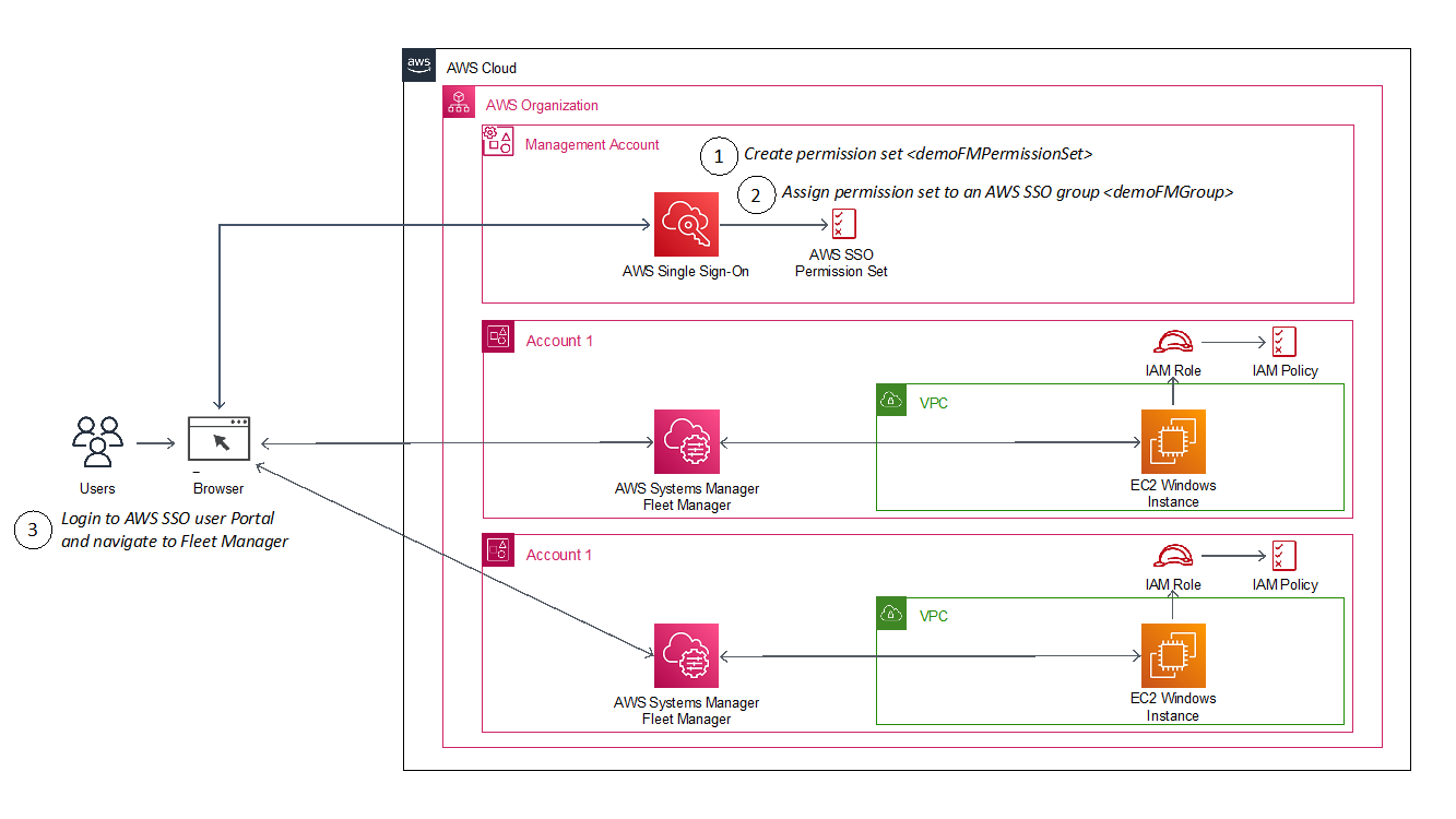
Figure 1: Architecture diagram showing steps implemented in this solution
How it works
The AWS SSO permission set creates a role in a target account that gives an authorized user permissions to use AWS Fleet Manager to sign into EC2 Windows instances. When a user chooses the role in the account, the user signs onto the AWS Fleet Manager console and selects the EC2 instance where they want to sign in.
AWS Fleet Manager creates a local Windows user account and a credential for that user, and then automates their sign-in to the instance.
To create an AWS SSO permission set
This procedure creates a permission set that grants assigned users and groups permissions to use AWS Fleet Manager for single sign-on to EC2 instances.
- From the AWS SSO console, go to AWS Accounts, select the Permission sets tab, select Create permission set and choose Create a custom permission set.
- Name your permission set, and fill out the required fields, making sure to select Create a custom permissions policy at the bottom of the page. See Sample custom permissions policy below for details on the policy.
- After creating the custom permissions policy, you can also apply optional tagging. When you are done, review and choose Create to complete creating your custom permission set, as shown in Figure 2.
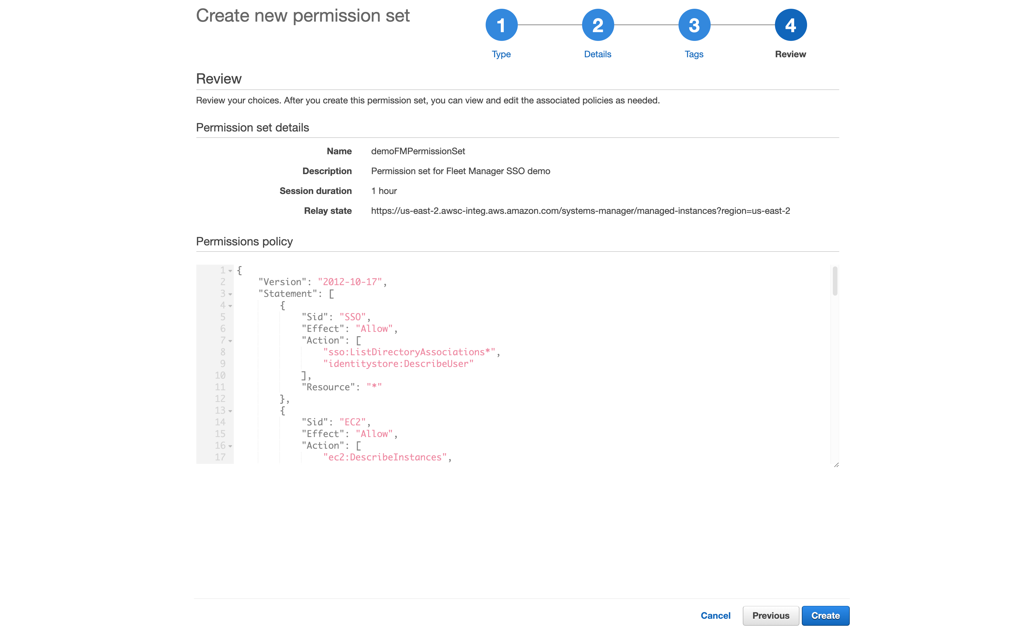
Figure 2: Reviewing the custom permission set
Sample custom permissions policy
This is the sample policy you’ll use; you can download it here.
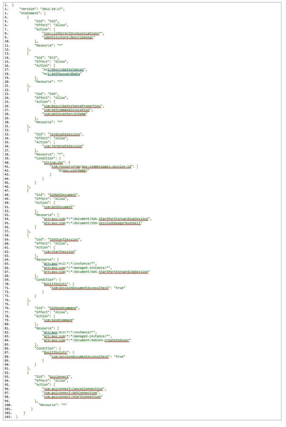
This permission policy contains a separate statement ID (Sid) for each service, with the required actions for each.
On line 84, notice the reference to an AWSSSO-CreateSSOUser document resource. This document is responsible for creating a local Windows account based on the AWS SSO logged in user, as well as setting/resetting the user’s password for automatic log in to the Windows instance.
On lines 96-98, you will see a new ssm-guiconnect action. This is used to make the secure connection to your EC2 Windows instance, and render the GUI desktop in the Fleet Manager console.
To assign your AWS SSO group
Assign your AWS SSO group to the AWS Fleet Manager permission set in your selected accounts
In this procedure, we will select two AWS accounts in our AWS organization, and grant our AWS SSO group access to the previously-created permission set that enables sign-in via Fleet manager.
- From the AWS SSO console, navigate to AWS accounts and select an account (for example, demoAccount1 and demoAccount2), as shown in Figure 3.
- Choose the Assign users button. If you wish, you may also assign access to multiple groups or to users individually.
- To enable multiple AWS SSO users to access this feature, choose an AWS SSO group from the Groups tab and then choose the Next button, as shown in Figure 4
- Select the permission set you created previously and choose the Next button.
- Review your choices, and press Submit to submit your assignments, as shown in Figure 6.
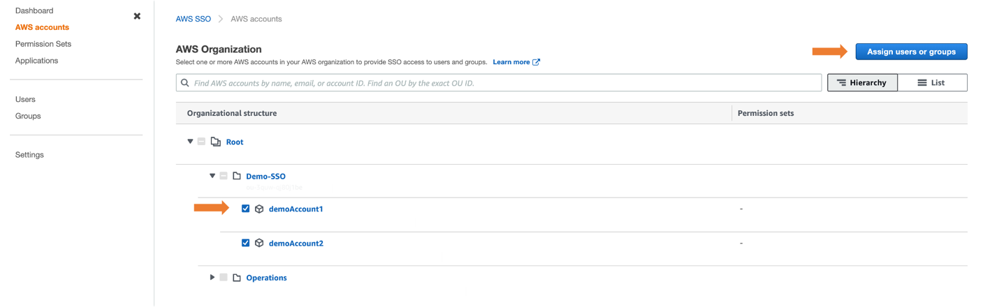
Figure 3: Selecting AWS Account to assign users or groups
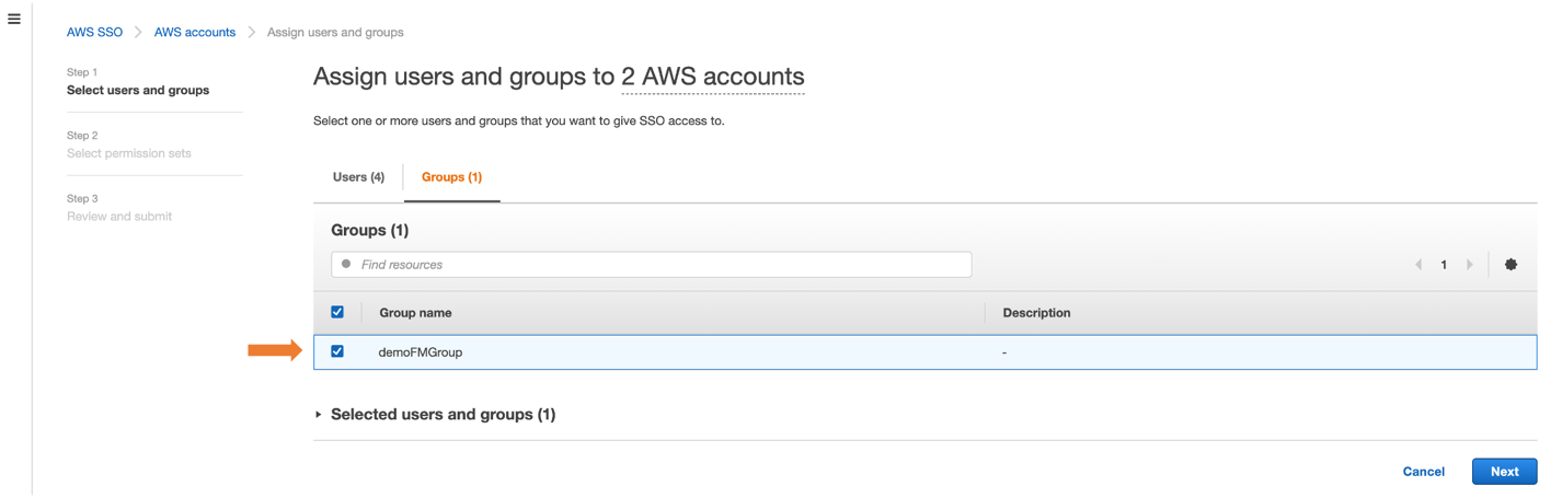
Figure 4: Assigning group to AWS accounts
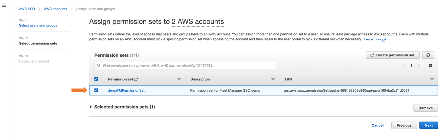
Figure 5: Selecting permission set to AWS accounts
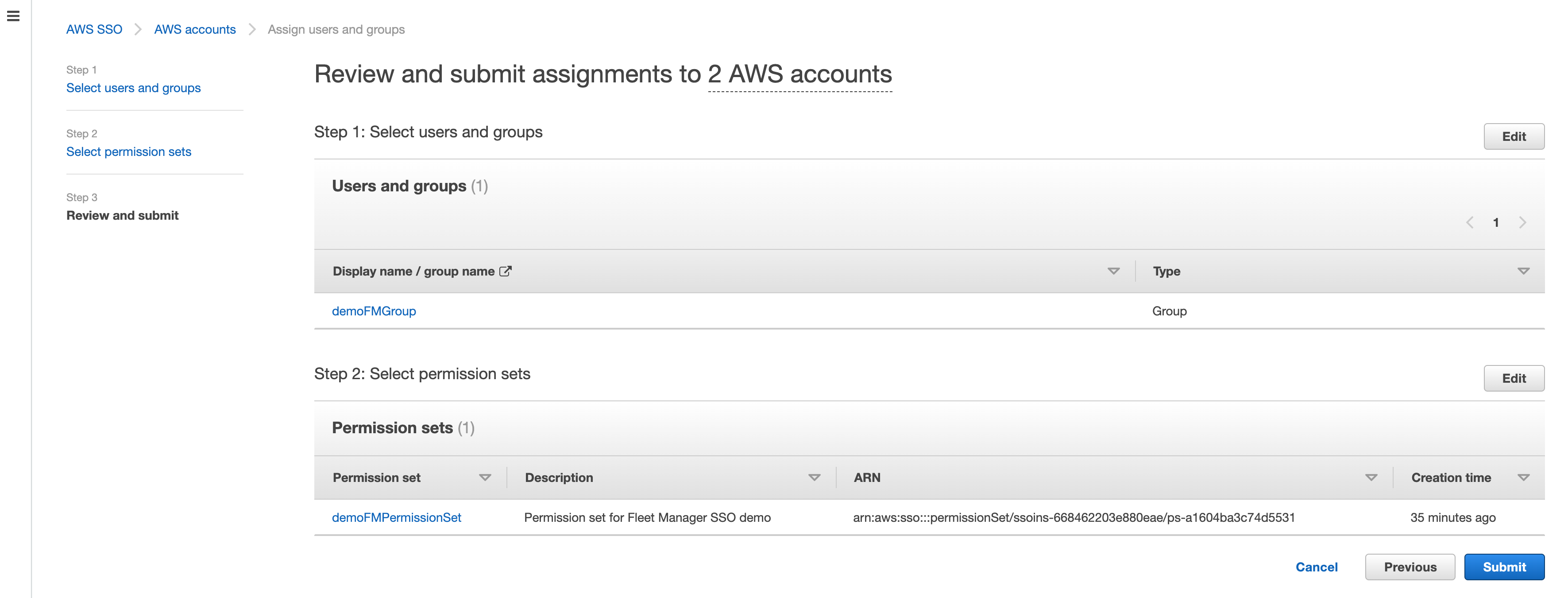
Figure 6: Reviewing submit assignments to AWS accounts
AWS SSO will now use the permission set definition to create a role in each selected account, which grants users access to sign in via Fleet Manager. Users gain access to that role by signing into the AWS SSO user portal.
To access Fleet Managed EC2 instances
- From the console, navigate to your AWS SSO user portal URL and login as any AWS SSO user who is a member of the group (e.g., demoFMGroup) you selected in step 3 above.
- From the AWS SSO user portal page, choose Management console and navigate to the Fleet Manager console where you have your EC2 Windows managed instance, as shown in Figure 7
- Select a managed Windows instance and select Instance actions and then Connect with Remote Desktop as shown in Figure 8.
- Select Single Sign-On and then select Connect, as shown in Figure 9.
- From the single session tab, we can see that AWS Fleet Manager created a local Windows Server user for the AWS SSO user (demoUser1).
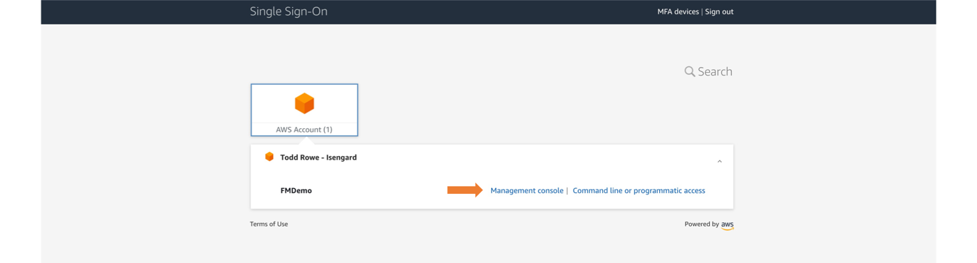
Figure 7: Navigating to the Management console from the user portal
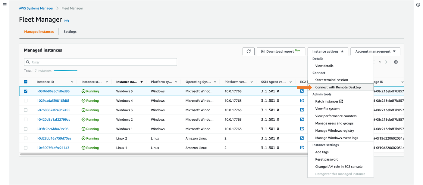
Figure 8: Connecting with Remote Desktop
This automatically logs you in using your AWS SSO credential. If this is the first time connecting to the instance, a new local user will be created.
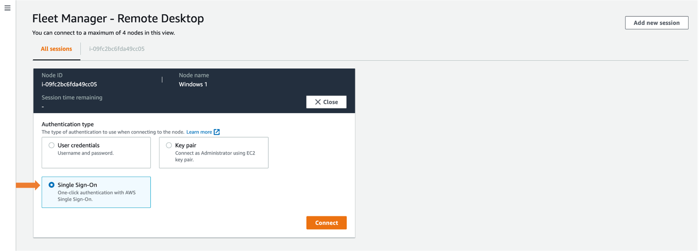
Figure 9: Selecting Single Sign-On
Once connected, you will see your EC2 Windows instance in the All sessions tab, enabling you to have up to four concurrent sessions in a single view, as shown in Figure 10. For a single session view, select the Instance ID tab.
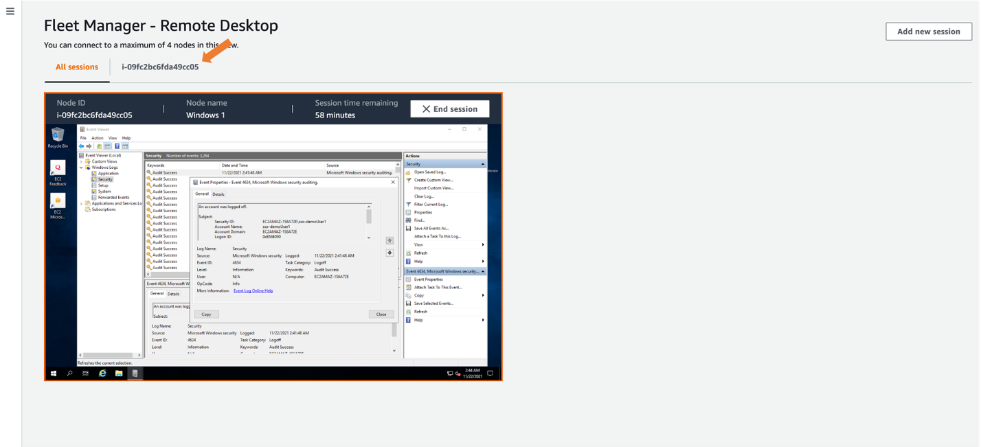
Figure 10: Selecting expanded desktop view
After creating the local user, AWS Fleet Manager used the credentials it created to sign into the EC2 Windows server as sso-demoUser1 from the Windows Event Viewer, giving you individual user logging on your EC2 Windows servers. These logs are also available from within the Fleet Manager console.
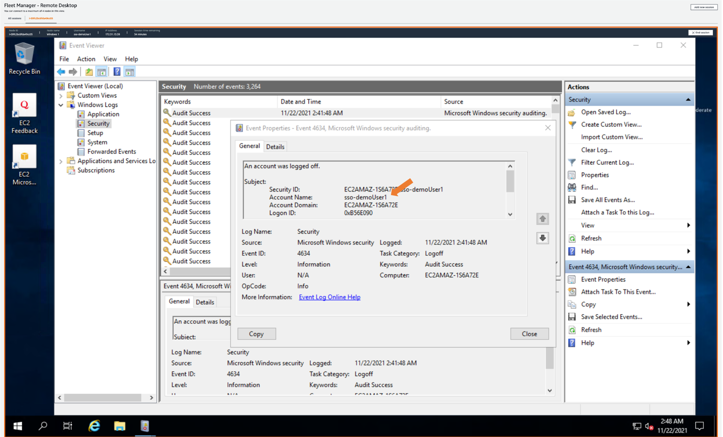
Figure 11: Showing AWS SSO username in Amazon EC2 Windows instance event log
Conclusion
This post described how to provide a single sign-in experience to Windows EC2 instances using AWS Fleet Manager with AWS Single Sign-On. Doing this allows you to create users in AWS SSO, or to connect any supported identity provider to AWS SSO, and to give users one-click access to their EC2 instances through AWS Fleet Manager.
This is done by creating an AWS SSO permission set that grants users access to AWS Fleet Manager, then assigning a group from AWS SSO to the permission set in the selected AWS accounts. Users can sign into the AWS SSO user portal, navigate to the AWS Fleet Manager, select their Windows EC2 instance, and land in the Windows user experience without having to enter Windows credentials separately.
To learn more about AWS SSO, visit the AWS Single Sign-On Documentation. To learn more about Fleet Manager, visit the AWS Systems Manager Fleet Manager Documentation.
If you have feedback about this blog post, submit comments in the Comments section below. If you have questions about this post, start a new thread on the AWS Single Sign-On forum.
Want more AWS Security news? Follow us on Twitter.