Post Syndicated from Alex Bate original https://www.raspberrypi.org/blog/designing-the-raspberry-pi-compute-module-4/
Raspberry Pi Compute Module 4 designer Dominic Plunkett was kind enough to let us sit him down for a talk with Eben, before writing up his experience of bringing our latest board to life for today’s blog post. Enjoy.
When I joined Raspberry Pi, James, Eben and Gordon already had some ideas on the features they would like to see on the new Compute Module 4, and it was down to me to take these ideas and turn them into a product. Many people think design is a nice linear process: ideas, schematics, PCB, and then final product. In the real world the design process isn’t like this, and to get the best designs I often try something and iterate around the design loop to get the best possible solution within the constraints.
Form factor change
Previous Compute Modules were all in a 200-pin SODIMM form factor, but two important considerations pushed us to think about moving to a different form factor: the need to expose useful interfaces of the BCM2711 that are not present in earlier SoCs, and the desire to add extra components, which meant we needed to route tracks differently to make space on the PCB for the additional parts.
Breaking out BCM2711’s high-speed interfaces
We knew we wanted to get the extra features of the BCM2711 out to the connector so that users could make use of them in their products. High-speed interfaces like PCIe and HDMI are so fast coming out of the BCM2711 that they need special IO pins that can’t also support GPIO: if we were to change the functionality of a GPIO pin to one of the new high-speed signals, this would break backwards compatibility.
We could consider adding some sort of multiplexer to swap between old and new functionality, but this would cost space on the PCB, as well as reducing the integrity of the fast signals. This consideration alone drives the design to a new pinout. We could have tried to use one of the SODIMM connectors with extra pins; while this would give a board with similar dimensions to the existing Compute Modules, it too would break compatibility.
PCB space for additional components
We also wanted to add extra items to the PCB, so PCB space to put the additional parts was an important consideration. If you look carefully at a Compute Module 3 you can see a lot of tracks carrying signals from one side of the SoC to the pins on the edge connector. These tracks take up valuable PCB space, preventing components being fitted there. We could add extra PCB layers to move these tracks from an outer layer to an inner layer, but these extra layers add to the cost of the product.
This was one of the main drivers in changing to having two connectors on different edges of the board: doing so saves having to route tracks all the way across the PCB. So we arrived at a design that incorporated a rough split of which signals were going to end up on each of the connectors. The exact order of the signals wasn’t yet defined.
Trial PCB layouts
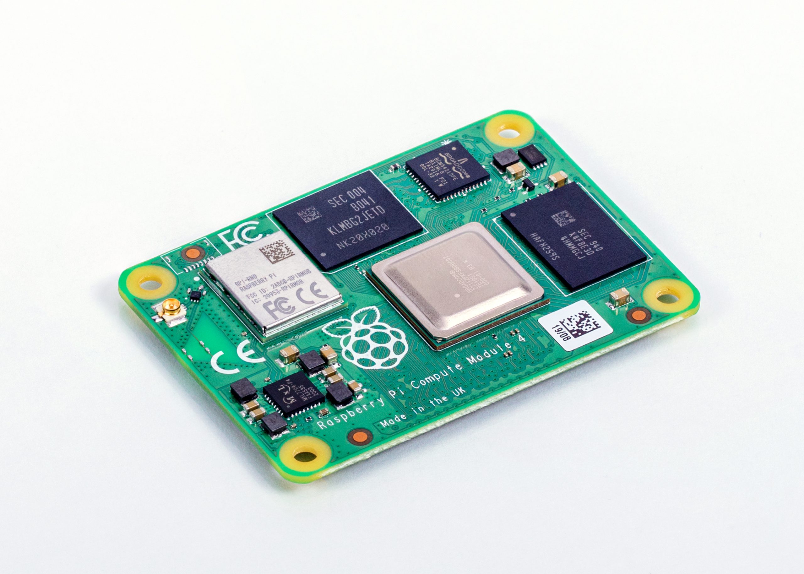
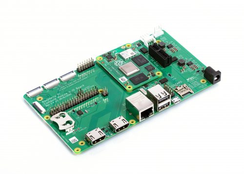
We experimented with trial PCB layouts for the Compute Module 4 and the CM4 IO Board to see how easy it would be to route the signals; even at this stage, the final size of the CM4 hadn’t been fixed. Over time, and after juggling parts around the PCB, I came to a sensible compromise. There were lots of things to consider, including the fact that the taller components had to go on the top side of the PCB.
The pinout was constantly being adjusted to an ordering that was a good compromise for both the CM4 and the IO Board. The IO Board layout was a really important consideration: after we made the first prototype boards, we decided to change the pinout slightly to make PCB layout on the IO Board even easier for the end user.
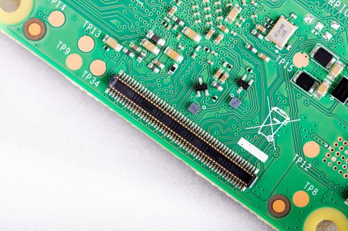
When the prototype Compute Module 4 IO Boards arrived back from manufacture, the connectors hadn’t arrived in time to be assembled by machine, so I fitted them by hand in the lab. Pro tip: if you have to fit connectors by hand, take your time to ensure they are lined up correctly, and use lots of flux to help the solder flow into the joints. Sometimes people use very small soldering iron tips thinking it will help; in fact, one of the goals of soldering is to get heat into the joint, and if the tip is too small it will be difficult to heat the solder joint sufficiently to make a good connection.
New features
Whilst it was easy to add some headline features like a second HDMI port, other useful features don’t grab as much attention. One example is that we have simplified the powering requirements. Previous Compute Modules required multiple PSUs to power a board, and the power-up sequence had to be exactly correct. Compute Module 4 simply requires a single +5V PSU.
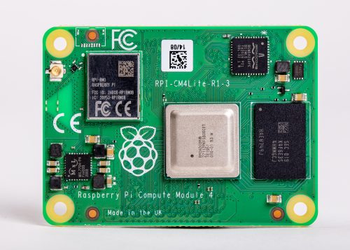
In fact, the simplest possible base board for Compute Module 4 just requires a +5V supply and one of the connectors and nothing else. You would need a CM4 variant with eMMC and wireless connectivity; you can boot the module with the eMMC, wireless connectivity gives you networking, and Bluetooth connectivity gives you access to IO devices. If you do add extra IO devices the CM4 also can provide a +3.3V supply to power those devices, avoiding the need for an external power supply.
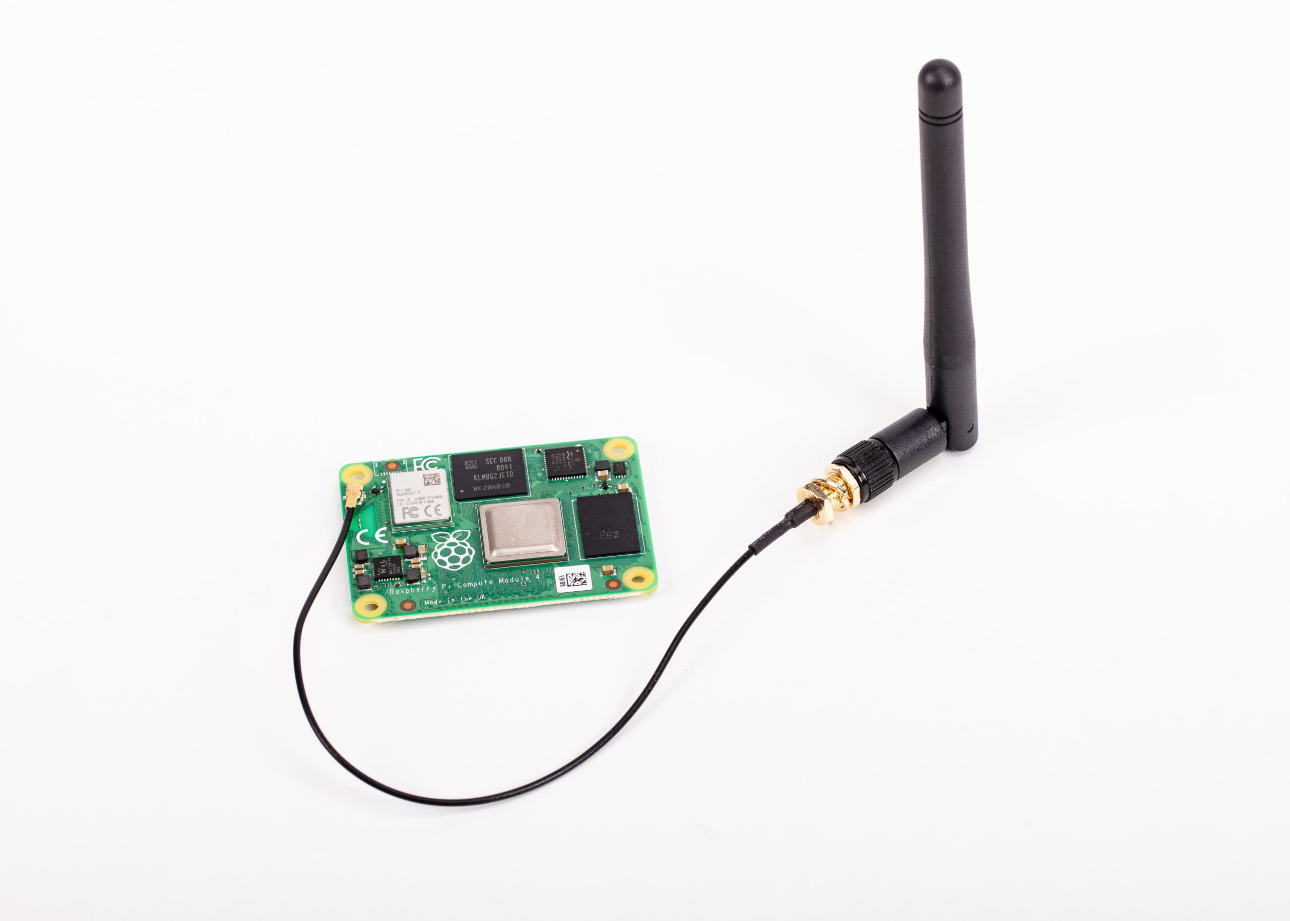
We have seen some customers experience issues with adding wireless interfaces to previous Compute Modules, so a really important requirement was to provide the option of wireless support. We wanted to be as flexible as possible, so we have added support for an external antenna. Because radio certification can be a very hard and expensive process, we have a pre-certified external antenna kit that can be supplied with Compute Module 4. This should greatly simplify product certification for end products, although engineering designers should check to make certain of meeting all local requirements.

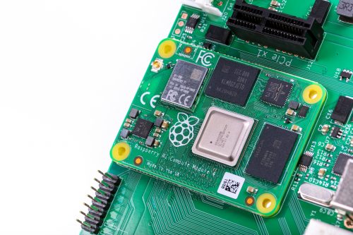
PCIe
This is probably the most exciting new interface to come to Compute Module 4. On the existing Raspberry Pi 4, this interface is used internally to add the XHCI controller which provides the USB 3 ports. By providing the PCIe externally, we are giving end users the choice of how they would like to use this interface. Many applications don’t need USB 3 performance, so the end user can make use of it in other ways — for NVMe drives, to take one example.
Ethernet
In order to have wired Ethernet connectivity with previous Compute Modules, you needed to add an external USB-to-Ethernet interface. This adds complexity to the IO board, and one of the aims of the new Compute Module 4 is to make interfacing to it simple. With this in mind, we added a physical Ethernet interface to CM4, and we also took the opportunity to add support for IEEE1588 to this. As a result, adding Gigabit wired networking to CM4 requires only the addition of a magjack; no extra silicon is needed. Because this is a true Gigabit interface, it is also faster than the USB-to-Ethernet interfaces that previous Compute Modules use.

Open-sourcing the Compute Module 4 IO Board design files
Early on in the process, we decided that we were going to open-source the design files for the Compute Module 4 IO Board. We used our big expensive CAD system for Compute Module 4 itself, and while we could have decided to do the design for the IO Board in the big CAD system too and then port it across to KiCAD, it’s easy to introduce issues in the porting process.
So, instead, we used KiCAD for the IO Board from the start, and the design files that come out of KiCAD are the same ones that we use in manufacture. During development I had both CAD systems running at the same time on the computer.
Easier integration and enhanced possibilities
We have made some big changes to our new Compute Module 4 range, and these should make integration much simpler for our customers. Many interfaces now just need a connector and power, and the new form factor should enable people to design more compact and more powerful products. I look forward to seeing what our customers create over the next few years with Compute Module 4.
Get your Compute Module 4
The new Raspberry Pi Compute Module 4 is available from our network of Approved Resellers. Head over to the Compute Module 4 product page and select your preferred variant to find your nearest reseller.
Can’t find a reseller near you? No worries. Many of our Approved Resellers ship internationally, so try a few other locations.
The post Designing the Raspberry Pi Compute Module 4 appeared first on Raspberry Pi.