Tag Archives: Compute Module

TOFU for Raspberry Pi Compute Module 4

Post Syndicated from Ashley Whittaker original https://www.raspberrypi.org/blog/tofu-for-raspberry-pi-compute-module-4/

In the latest issue of Custom PC magazine, Gareth Halfacree reviews Oratek’s TOFU, a carrier printed circuit board for Raspberry Pi Compute Module 4.

The launch of the Raspberry Pi Compute Module 4 family (reviewed in Issue 209) last year sparked an entirely unsurprising explosion of interest in designing carrier boards. This was aided in no small part by the Raspberry Pi Foundation’s decision to release its own in-house carrier board design under a permissive licence from which others could springboard with their own creations.

TOFU for Compute Module 4
Smartly designed with some clever features, the Tofu is a great carrier for a Raspberry Pi CM4 or compatible boards

Oratek doesn’t hide its inspiration. ‘Inspired by the official CM4IO board,’ chief executive Aurélien Essig openly admits, ‘it is intended for industrial applications. With user-friendly additions, it may also be used by enthusiasts looking for a compact yet complete solution to interface the many inputs and outputs of the single-board computer.’

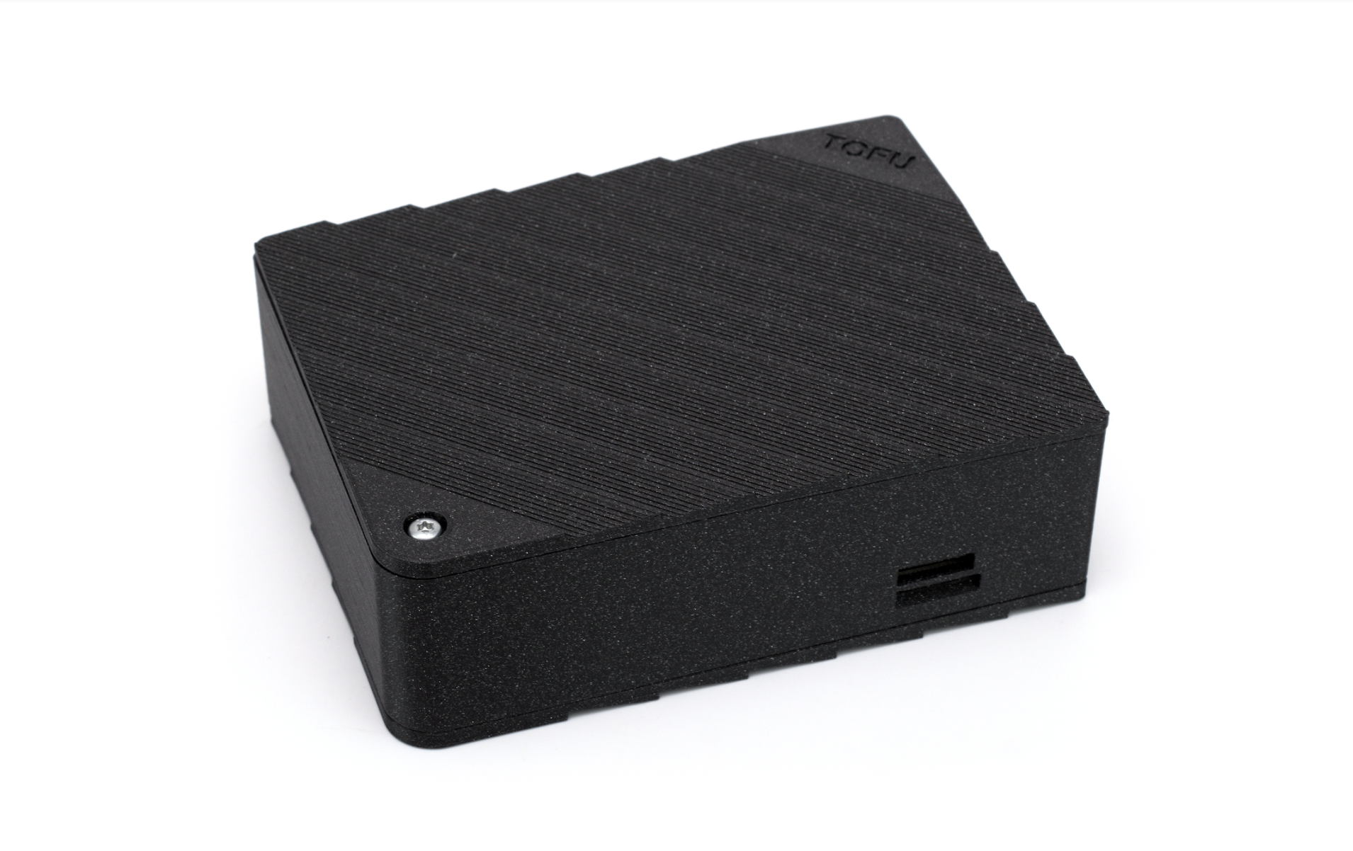
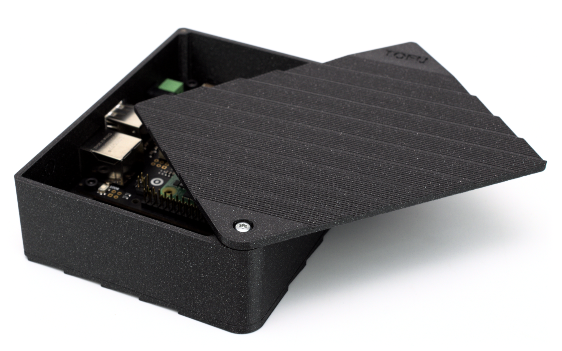
The board is undeniably compact, although it bulks out when paired with the optional 3D-printed Switchblade Enclosure designed by Studio Raphaël Lutz. The reason for the name is that there are hinged lids on the top and bottom, which swing out for easy access, locking into place with small magnets when closed.

An optional adaptor converts the M.2 B-Key slot into an M-Key for NVMe storage

At least, that’s the theory. In practice, the magnets are a little weak; there’s also no way to fasten the lid shut beyond overtightening the screw in the corner. Otherwise, it’s a well-designed enclosure with top and bottom ventilation. Sadly, that’s not enough to prevent a Compute Module 4 from hitting its thermal throttle point under sustained heavy load, so you’ll need to budget for a third-party heatsink or fan accessory.

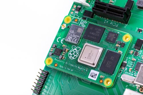
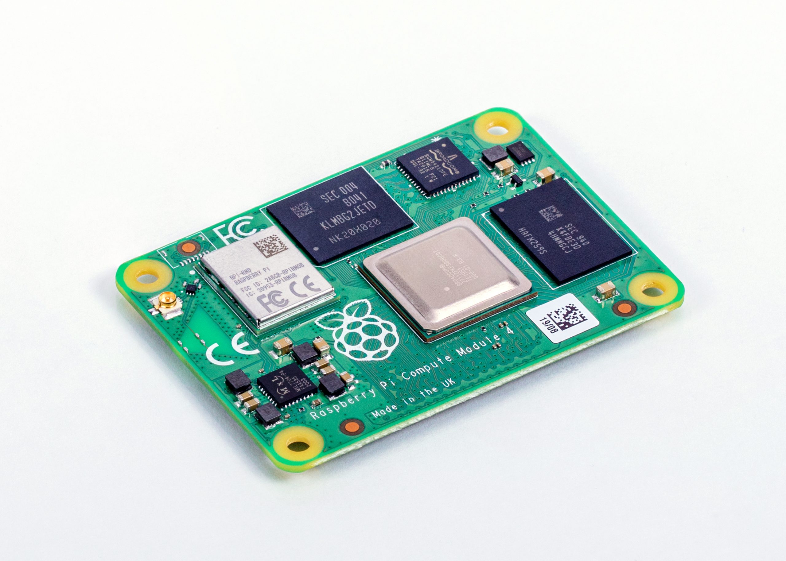
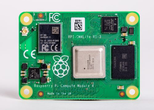
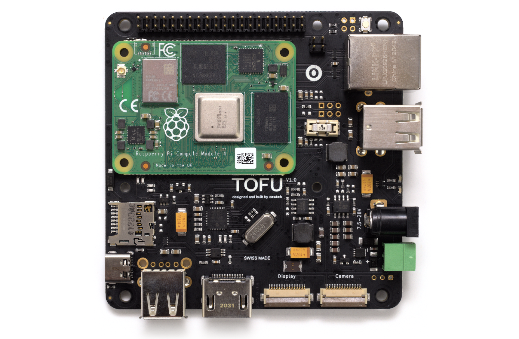
The Tofu board itself is well thought out, and finished in an attractive black. Two high-density connectors accept a Raspberry Pi Compute Module 4 board – or one of the increasing number of pin-compatible alternatives on the market, although you’ll need to provide your own mounting bolts.

TOFU for Compute Module 4 case
The 3D-printed case comes in an attractive ‘galaxy’ finish, but it isn’t cheap

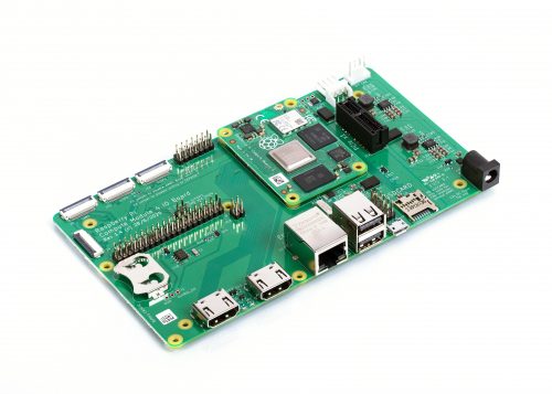
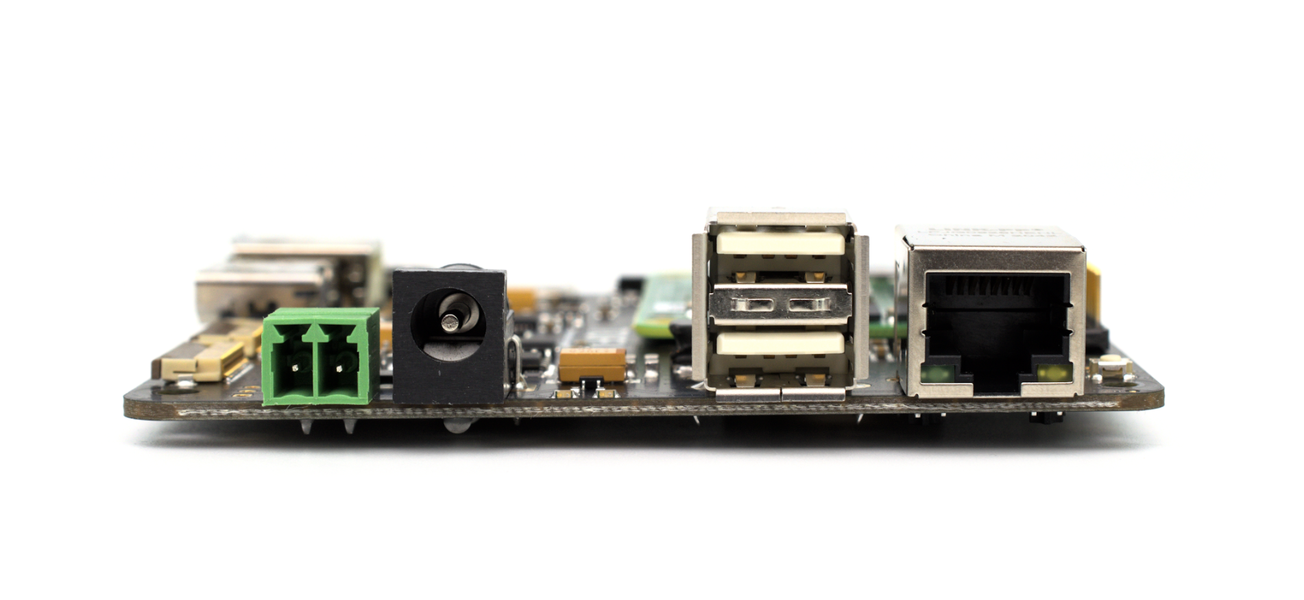
The 90 x 90mm board then breaks out as many features of the computer-on-module as possible. The right side houses a Gigabit Ethernet port with Power-over-Ethernet (PoE) support if you add a Raspberry Pi PoE HAT or PoE+ HAT, two USB 2 Type-A ports, along with barrel-jack and 3.5mm terminal-block power inputs. These accept any input from 7.5V to 28V, which is brought out to an internal header for accessories that need more power than is available on the 40-pin general-purpose input/output (GPIO) port.

Meanwhile, the bottom has 22-pin connectors for Camera Serial Interface (CSI) and Display Serial Interface (DSI) peripherals, a full-sized HDMI port and an additional USB 2 port. These ports aren’t available outside the Switchblade Case by default, although a quick snap of the already-measured capped-off holes fixes that.

TOFU for Compute Module 4 case
Both the top and bottom rotate out of the way for easy access to the hardware inside

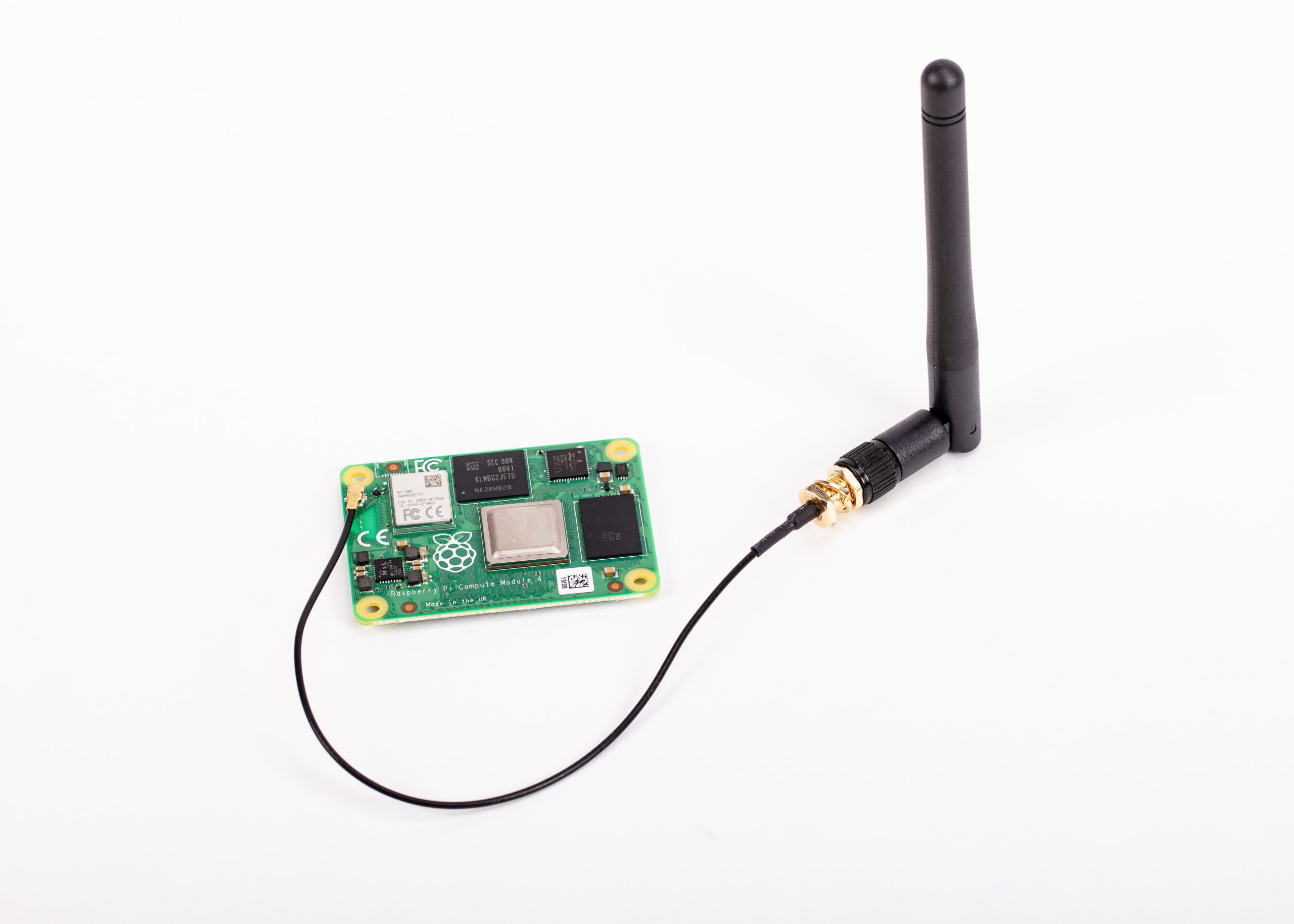
The left side includes a micro-SD slot for Compute Module 4 variants without on-board eMMC storage, plus a micro-SIM slot – hinting at another feature that becomes visible once the board is flipped. There’s also a USB Type-C port, which can be used for programming or as an On-The-Go (OTG) port. Oddly, there’s no cut-out at all for this in the Switchblade Case; if you want one, you’ll need to take a drill and file to it.

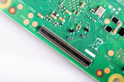
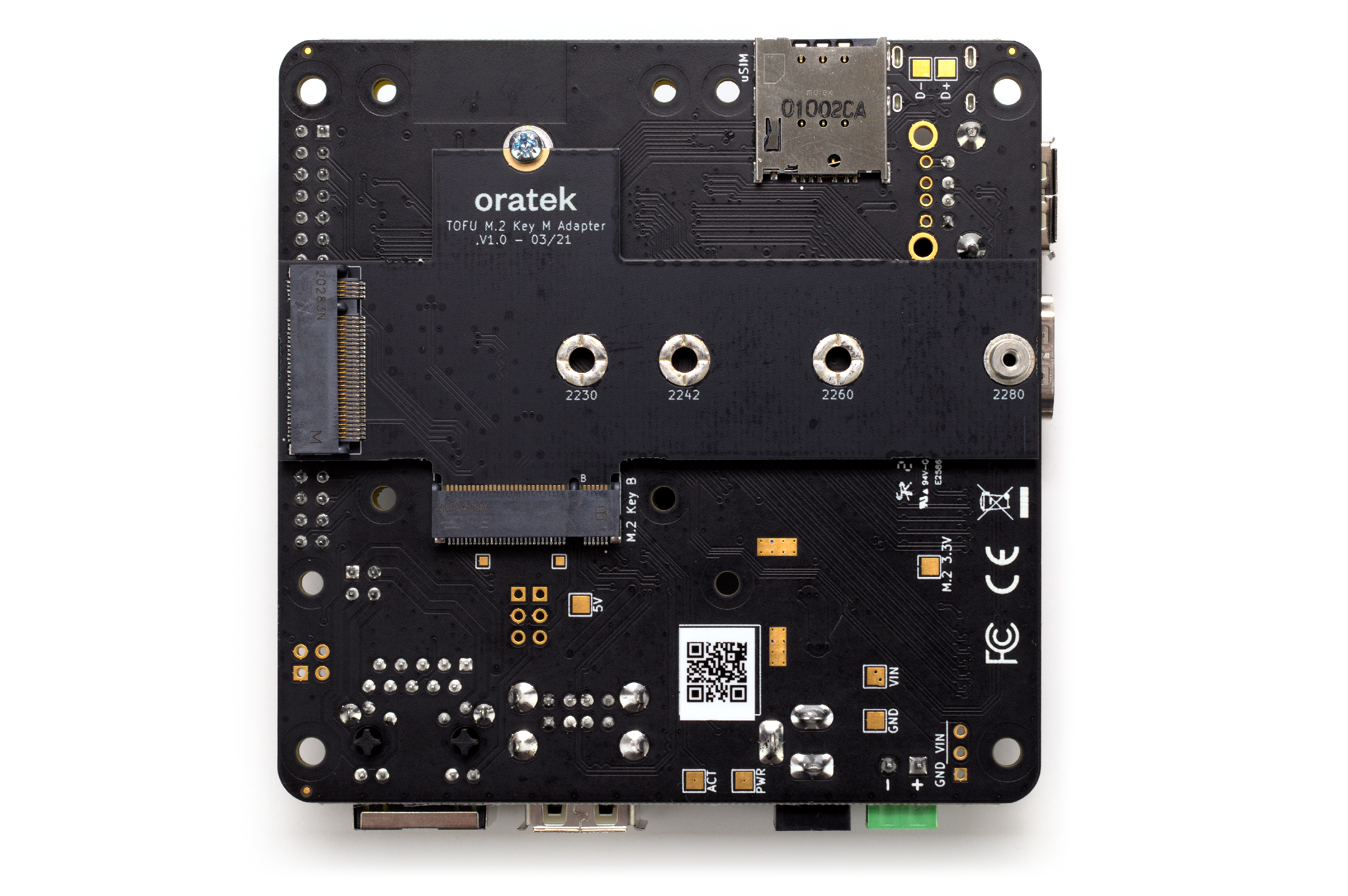
Turning over the board reveals the micro-SIM slot’s purpose. The Compute Module 4’s PCI-E lane is brought out to an M.2 B-Key slot, providing a connection for additional hardware including 3G/4G modems. For storage, you can use an optional adaptor board to convert it to M-Key for Non-Volatile Memory Express (NVMe) devices, with a spacer fitted for 2230, 2242, 2260, or 2280 form factor drives.

TOFU for Compute Module 4 ports
The Tofu has plenty of ports, but no USB 3

That’s not as flexible as it sounds, unfortunately. The spacer is soldered in place and needs to be chosen at the time of ordering. If you want to switch to a different-sized drive, you’ll need another adaptor.

There’s one other design point that makes the Tofu stand out: the inclusion of a user-replaceable fuse, a Littelfuse Nano 2 3.5A unit that was originally designed for automotive projects. 

While it’s primarily there for protection, it also enables you to cut off the on-board power supply when the board is driven through PoE. With the fuse in place, there’s clearly audible coil whine, which can be silenced by carefully popping the fuse out of its holder. Just remember to put it back in if you stop using PoE.

The biggest problem is price. At 99 CHF (around £78 ex VAT) you’ll be into triple figures by the time you’ve picked up a suitable power supply and Compute Module 4 board. The M.2 M-Key adaptor adds a further 19 CHF (around £15 ex VAT), and the Switchblade Case is another 35 CHF (around £28 ex VAT). If you have access to a 3D printer, you can opt to print the latter yourself, but you’ll still pay 8 CHF (around £6 ex VAT) for access to the files.

The Tofu is available to order now from oratek.com. Compatible Raspberry Pi Compute Module 4 boards can be found at the usual stockists.

Custom PC issue 217 out NOW!

You can read more features like this one in Custom PC issue 217, available directly from Raspberry Pi Press — we deliver worldwide.

custom pc front cover

And if you’d like a handy digital version of the magazine, you can also download issue 217 for free in PDF format.

The post TOFU for Raspberry Pi Compute Module 4 appeared first on Raspberry Pi.

YouTuber Jeff Geerling reviews Raspberry Pi Compute Module 4

Post Syndicated from Ashley Whittaker original https://www.raspberrypi.org/blog/youtuber-jeff-geerling-reviews-raspberry-pi-compute-module-4/

We love seeing how quickly our community of makers responds when we drop a new product, and one of the fastest off the starting block when we released the new Raspberry Pi Compute Module 4 on Monday was YouTuber Jeff Geerling.

Jeff Geerling

We made him keep it a secret until launch day after we snuck one to him early so we could see what one of YouTube’s chief advocates for our Compute Module line thought of our newest baby.

So how does our newest board compare to its predecessor, Compute Module 3+? In Jeff’s first video (above) he reviews some of Compute Module 4’s new features, and he has gone into tons more detail in this blog post.

Jeff also took to live stream for a Q&A (above) covering some of the most asked questions about Compute Module 4, and sharing some more features he missed in his initial review video.

His next video (above) is pretty cool. Jeff explains:

“Everyone knows you can overclock the Pi 4. But what happens when you overclock a Compute Module 4? The results surprised me!”

Jeff Geerling

And again, there’s tons more detail on temperature measurement, storage performance, and more on Jeff’s blog.

Top job, Jeff. We have our eyes on your channel for more videos on Compute Module 4, coming soon.

If you like what you see on his YouTube channel, you can also sponsor Jeff on GitHub, or support his work via Patreon.

The post YouTuber Jeff Geerling reviews Raspberry Pi Compute Module 4 appeared first on Raspberry Pi.

Designing the Raspberry Pi Compute Module 4

Post Syndicated from Alex Bate original https://www.raspberrypi.org/blog/designing-the-raspberry-pi-compute-module-4/

Raspberry Pi Compute Module 4 designer Dominic Plunkett was kind enough to let us sit him down for a talk with Eben, before writing up his experience of bringing our latest board to life for today’s blog post. Enjoy.

When I joined Raspberry Pi, James, Eben and Gordon already had some ideas on the features they would like to see on the new Compute Module 4, and it was down to me to take these ideas and turn them into a product. Many people think design is a nice linear process: ideas, schematics, PCB, and then final product. In the real world the design process isn’t like this, and to get the best designs I often try something and iterate around the design loop to get the best possible solution within the constraints.

Form factor change

Previous Compute Modules were all in a 200-pin SODIMM form factor, but two important considerations pushed us to think about moving to a different form factor: the need to expose useful interfaces of the BCM2711 that are not present in earlier SoCs, and the desire to add extra components, which meant we needed to route tracks differently to make space on the PCB for the additional parts.

Breaking out BCM2711’s high-speed interfaces

We knew we wanted to get the extra features of the BCM2711 out to the connector so that users could make use of them in their products. High-speed interfaces like PCIe and HDMI are so fast coming out of the BCM2711 that they need special IO pins that can’t also support GPIO: if we were to change the functionality of a GPIO pin to one of the new high-speed signals, this would break backwards compatibility.

We could consider adding some sort of multiplexer to swap between old and new functionality, but this would cost space on the PCB, as well as reducing the integrity of the fast signals. This consideration alone drives the design to a new pinout. We could have tried to use one of the SODIMM connectors with extra pins; while this would give a board with similar dimensions to the existing Compute Modules, it too would break compatibility.

Compute Module 4 mounted on the IO Board

PCB space for additional components

We also wanted to add extra items to the PCB, so PCB space to put the additional parts was an important consideration. If you look carefully at a Compute Module 3 you can see a lot of tracks carrying signals from one side of the SoC to the pins on the edge connector. These tracks take up valuable PCB space, preventing components being fitted there. We could add extra PCB layers to move these tracks from an outer layer to an inner layer, but these extra layers add to the cost of the product.

This was one of the main drivers in changing to having two connectors on different edges of the board: doing so saves having to route tracks all the way across the PCB. So we arrived at a design that incorporated a rough split of which signals were going to end up on each of the connectors. The exact order of the signals wasn’t yet defined.

Trial PCB layouts

We experimented with trial PCB layouts for the Compute Module 4 and the CM4 IO Board to see how easy it would be to route the signals; even at this stage, the final size of the CM4 hadn’t been fixed. Over time, and after juggling parts around the PCB, I came to a sensible compromise. There were lots of things to consider, including the fact that the taller components had to go on the top side of the PCB.

The pinout was constantly being adjusted to an ordering that was a good compromise for both the CM4 and the IO Board. The IO Board layout was a really important consideration: after we made the first prototype boards, we decided to change the pinout slightly to make PCB layout on the IO Board even easier for the end user.

When the prototype Compute Module 4 IO Boards arrived back from manufacture, the connectors hadn’t arrived in time to be assembled by machine, so I fitted them by hand in the lab. Pro tip: if you have to fit connectors by hand, take your time to ensure they are lined up correctly, and use lots of flux to help the solder flow into the joints. Sometimes people use very small soldering iron tips thinking it will help; in fact, one of the goals of soldering is to get heat into the joint, and if the tip is too small it will be difficult to heat the solder joint sufficiently to make a good connection.

Compute Module 4 IO Board

New features

Whilst it was easy to add some headline features like a second HDMI port, other useful features don’t grab as much attention. One example is that we have simplified the powering requirements. Previous Compute Modules required multiple PSUs to power a board, and the power-up sequence had to be exactly correct. Compute Module 4 simply requires a single +5V PSU.

In fact, the simplest possible base board for Compute Module 4 just requires a +5V supply and one of the connectors and nothing else. You would need a CM4 variant with eMMC and wireless connectivity; you can boot the module with the eMMC, wireless connectivity gives you networking, and Bluetooth connectivity gives you access to IO devices. If you do add extra IO devices the CM4 also can provide a +3.3V supply to power those devices, avoiding the need for an external power supply.

We have seen some customers experience issues with adding wireless interfaces to previous Compute Modules, so a really important requirement was to provide the option of wireless support. We wanted to be as flexible as possible, so we have added support for an external antenna. Because radio certification can be a very hard and expensive process, we have a pre-certified external antenna kit that can be supplied with Compute Module 4. This should greatly simplify product certification for end products, although engineering designers should check to make certain of meeting all local requirements.

Antenna Kit and Compute Module 4

PCIe

This is probably the most exciting new interface to come to Compute Module 4. On the existing Raspberry Pi 4, this interface is used internally to add the XHCI controller which provides the USB 3 ports. By providing the PCIe externally, we are giving end users the choice of how they would like to use this interface. Many applications don’t need USB 3 performance, so the end user can make use of it in other ways — for NVMe drives, to take one example.

Ethernet

In order to have wired Ethernet connectivity with previous Compute Modules, you needed to add an external USB-to-Ethernet interface. This adds complexity to the IO board, and one of the aims of the new Compute Module 4 is to make interfacing to it simple. With this in mind, we added a physical Ethernet interface to CM4, and we also took the opportunity to add support for IEEE1588 to this. As a result, adding Gigabit wired networking to CM4 requires only the addition of a magjack; no extra silicon is needed. Because this is a true Gigabit interface, it is also faster than the USB-to-Ethernet interfaces that previous Compute Modules use.

Raspberry Pi Compute Module 4

Open-sourcing the Compute Module 4 IO Board design files

Early on in the process, we decided that we were going to open-source the design files for the Compute Module 4 IO Board. We used our big expensive CAD system for Compute Module 4 itself, and while we could have decided to do the design for the IO Board in the big CAD system too and then port it across to KiCAD, it’s easy to introduce issues in the porting process.

So, instead, we used KiCAD for the IO Board from the start, and the design files that come out of KiCAD are the same ones that we use in manufacture. During development I had both CAD systems running at the same time on the computer.

Easier integration and enhanced possibilities

We have made some big changes to our new Compute Module 4 range, and these should make integration much simpler for our customers. Many interfaces now just need a connector and power, and the new form factor should enable people to design more compact and more powerful products. I look forward to seeing what our customers create over the next few years with Compute Module 4.

High-density connector on board underside

Get your Compute Module 4

The new Raspberry Pi Compute Module 4 is available from our network of Approved Resellers. Head over to the Compute Module 4 product page and select your preferred variant to find your nearest reseller.

Can’t find a reseller near you? No worries. Many of our Approved Resellers ship internationally, so try a few other locations.

The post Designing the Raspberry Pi Compute Module 4 appeared first on Raspberry Pi.

Raspberry Pi Compute Module 4 on sale now from $25

Post Syndicated from original https://www.raspberrypi.org/blog/raspberry-pi-compute-module-4/

It’s become a tradition that we follow each Raspberry Pi model with a system-on-module variant based on the same core silicon. Raspberry Pi 1 gave rise to the original Compute Module in 2014; Raspberry Pi 3 and 3+ were followed by Compute Module 3 and 3+ in 2017 and 2019 respectively. Only Raspberry Pi 2, our shortest-lived flagship product at just thirteen months, escaped the Compute Module treatment.

It’s been sixteen months since we unleashed Raspberry Pi 4 on the world, and today we’re announcing the launch of Compute Module 4, starting from $25.

Over half of the seven million Raspberry Pi units we sell each year go into industrial and commercial applications, from digital signage to thin clients to process automation. Many of these applications use the familiar single-board Raspberry Pi, but for users who want a more compact or custom form factor, or on-board eMMC storage, Compute Module products provide a simple way to move from a Raspberry Pi-based prototype to volume production.

A step change in performance

Built on the same 64-bit quad-core BCM2711 application processor as Raspberry Pi 4, our Compute Module 4 delivers a step change in performance over its predecessors: faster CPU cores, better multimedia, more interfacing capabilities, and, for the first time, a choice of RAM densities and a wireless connectivity option.

Raspberry Pi Compute Module 4

You can find detailed specs here, but let’s run through the highlights:

  • 1.5GHz quad-core 64-bit ARM Cortex-A72 CPU
  • VideoCore VI graphics, supporting OpenGL ES 3.x
  • 4Kp60 hardware decode of H.265 (HEVC) video
  • 1080p60 hardware decode, and 1080p30 hardware encode of H.264 (AVC) video
  • Dual HDMI interfaces, at resolutions up to 4K
  • Single-lane PCI Express 2.0 interface
  • Dual MIPI DSI display, and dual MIPI CSI-2 camera interfaces
  • 1GB, 2GB, 4GB or 8GB LPDDR4-3200 SDRAM
  • Optional 8GB, 16GB or 32GB eMMC Flash storage
  • Optional 2.4GHz and 5GHz IEEE 802.11b/g/n/ac wireless LAN and Bluetooth 5.0
  • Gigabit Ethernet PHY with IEEE 1588 support
  • 28 GPIO pins, with up to 6 × UART, 6 × I2C and 5 × SPI
Compute Module 4 Lite (without eMMC Flash memory)
Compute Module 4 Lite, our variant without eMMC Flash memory

New, more compact form factor

Compute Module 4 introduces a brand new form factor, and a compatibility break with earlier Compute Modules. Where previous modules adopted the JEDEC DDR2 SODIMM mechanical standard, with I/O signals on an edge connector, we now bring I/O signals to two high-density perpendicular connectors (one for power and low-speed interfaces, and one for high-speed interfaces).

This significantly reduces the overall footprint of the module on its carrier board, letting you achieve smaller form factors for your products.

High-density connector on board underside

32 variants

With four RAM options, four Flash options, and optional wireless connectivity, we have a total of 32 variants, with prices ranging from $25 (for the 1GB RAM, Lite, no wireless variant) to $90 (for the 8GB RAM, 32GB Flash, wireless variant).

We’re very pleased that the four variants with 1GB RAM and no wireless keep the same price points ($25, $30, $35, and $40) as their Compute Module 3+ equivalents: once again, we’ve managed to pack a lot more performance into the platform without increasing the price.

You can find the full price list in the Compute Module 4 product brief.

Compute Module 4 IO Board

To help you get started with Compute Module 4, we are also launching an updated IO Board. Like the IO boards for earlier Compute Module products, this breaks out all the interfaces from the Compute Module to standard connectors, providing a ready-made development platform and a starting point for your own designs.

Compute Module 4 IO Board

The IO board provides:

  • Two full-size HDMI ports
  • Gigabit Ethernet jack
  • Two USB 2.0 ports
  • MicroSD card socket (only for use with Lite, no-eMMC Compute Module 4 variants)
  • PCI Express Gen 2 x1 socket
  • HAT footprint with 40-pin GPIO connector and PoE header
  • 12V input via barrel jack (supports up to 26V if PCIe unused)
  • Camera and display FPC connectors
  • Real-time clock with battery backup

CAD for the IO board is available in KiCad format. You may recall that a few years ago we made a donation to support improvements to KiCad’s differential pair routing and track length control features; now you can use this feature-rich, open-source PCB layout package to design your own Compute Module carrier board.

Compute Module 4 mounted on the IO Board

In addition to serving as a development platform and reference design, we expect the IO board to be a finished product in its own right: if you require a Raspberry Pi that supports a wider range of input voltages, has all its major connectors in a single plane, or allows you to attach your own PCI Express devices, then Compute Module 4 with the IO Board does what you need.

We’ve set the price of the bare IO board at just $35, so a complete package including a Compute Module starts from $60.

Compute Module 4 Antenna Kit

We expect that most users of wireless Compute Module variants will be happy with the on-board PCB antenna. However, in some circumstances – for example, where the product is in a metal case, or where it is not possible to provide the necessary ground plane cut-out under the module – an external antenna will be required. The Compute Module 4 Antenna Kit comprises a whip antenna, with a bulkhead screw fixture and U.FL connector to attach to the socket on the module.

Antenna Kit and Compute Module 4

When using ether the Antenna Kit or the on-board antenna, you can take advantage of our modular certification to reduce the conformance testing costs for your finished product. And remember, the Raspberry Pi Integrator Programme is there to help you get your Compute Module-based product to market.

Our most powerful Compute Module

This is our best Compute Module yet. It’s also our first product designed by Dominic Plunkett, who joined us almost exactly a year ago.

I sat down with Dominic last week to discuss Compute Module 4 in greater detail, and you can find the video of our conversation here. Dominic will also be sharing more technical detail in the blog tomorrow.

In the meantime, check out the Compute Module 4 page for the datasheet and other details, and start thinking about what you’ll build with Compute Module 4.

The post Raspberry Pi Compute Module 4 on sale now from $25 appeared first on Raspberry Pi.