Tag Archives: FlinkSQL

The Hugo evolution: Engineering Grab’s unified, one-click data ingestion platform with Apache Flink

Post Syndicated from Grab Tech original https://engineering.grab.com/one-click-data-ingestion-platform-with-apache-flink

Introduction

Data drives every decision we make at Grab. As our operations scale, so does our need for robust, real-time data ingestion and processing frameworks. Enter Hugo: our self-service data platform that has long empowered teams to seamlessly route data into our Data Lake. Today, Hugo is evolving. We have taken previously siloed onboarding workflows and transformed them into one seamless, unified journey to truly democratize data ingestion and maximize efficiency.

In this blog, we’ll share how Hugo turns complex engineering hurdles into a frictionless, self-service reality. By moving away from siloed workflows, we’ve achieved a unified pipeline experience where one-click RDS CDC and self-service Kafka ingestion are the new standard.

Background
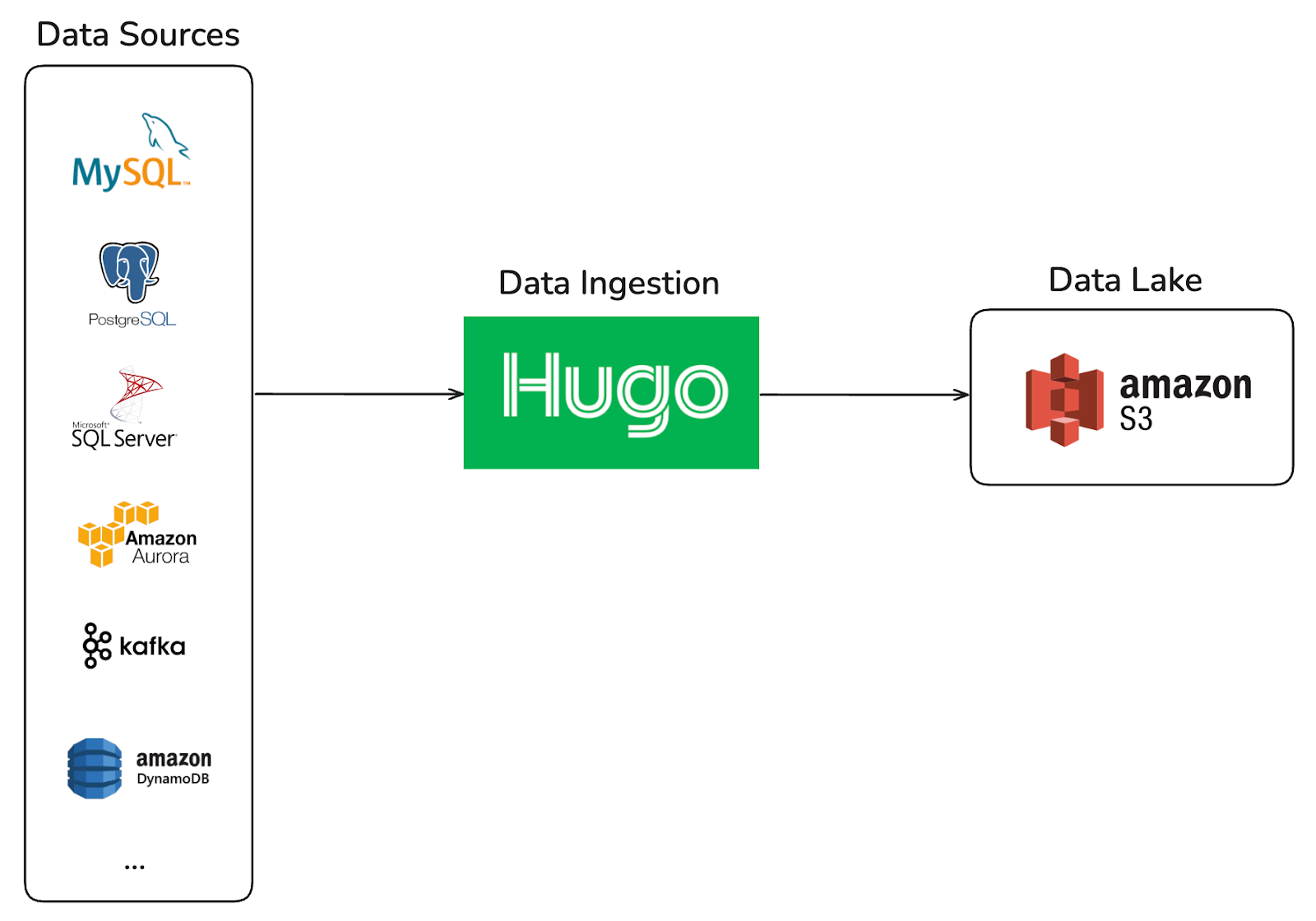
Figure 1. Hugo – Ingests data from every source into Grab’s data lake.

Hugo was originally designed as a self-service platform for batch-oriented data ingestion into the Data Lake, built on a single computation engine, Spark. It provided a centralized and streamlined onboarding experience for data sources such as MySQL, Aurora, PostgreSQL, and DynamoDB.

As the organization’s data platform evolved toward near real-time ingestion, Hugo expanded to support streaming pipelines from Kafka and MySQL binlog. This evolution introduced a more distributed architecture, where ingestion workflows spanned multiple systems, including Kafka Connect, Sprinkler (an in-house Go-based S3 writer), and Hugo.

The siloed past: A multi-platform hurdle

While powerful, the expanded architecture introduced significant onboarding friction. Creating a single data pipeline now requires users to coordinate across multiple platforms, each with its own configuration model and operational semantics. As a result, the onboarding journey became fragmented and difficult to navigate, especially for new users.

The common challenge during onboarding was helping users understand how configurations mapped across systems.

For MySQL CDC pipelines, users often asked, “I’ve already configured Kafka Connect, what values do I need to provide in Hugo?” after setting up a Kafka Connect job. This revealed a gap in abstraction between systems, requiring users to manually translate concepts and configurations across different platforms.

For Kafka pipelines, users frequently struggled with schema evolution in the data lake. Common questions included: “How should I update the data lake schema?” and “I’ve already updated the Protobuf schema for this Kafka topic, why isn’t the latest schema reflected in the data lake?” These issues highlighted unclear expectations around schema propagation and synchronization across the pipeline.

This multi-step, cross-system dependency increased cognitive load, slowed down onboarding, and created coordination overhead between platform teams and users.

The Hugo evolution: A unified ingestion platform

Hugo’s new, deeply automated ingestion framework, built with a custom automation layer and Apache Flink, has unified workflows and retired Sprinkler and Kafka Connect. This evolution converted manual, artisanal work into a streamlined, self-service experience, with custom automation serving as the “intelligent chassis” for the entire user journey.

The Hugo ingestion architecture: Engineering a unified flow

One-click MySQL CDC pipelines

The transition to a unified modernized pipeline powered by Flink CDC shifts the data ingestion architecture from a fragmented, high-maintenance toolchain into a single, end-to-end orchestrated platform. By reading the database binlog directly and embedding the lifecycle within a centralized control plane, the modernized approach drastically reduces operational overhead, eliminates data mismatch risks, and cuts onboarding times from days to minutes. Below are the core advantages of adopting Flink:

  • Minimal operational overhead: It reduces the footprint from 4 disparate components (Kafka Connect, topics, Sprinkler app, and Spark) to just 2 core components managed via a single control plane.
  • Eliminated schema risk: It replaces brittle, manually coded Go DTOs, which caused frequent schema deviations, with automated schema detection and dynamic validation.
  • Streamlined architecture: It eliminates the intermediary Kafka hop. Flink reads the MySQL binlog directly and pushes straight to a queryable Hive table via an integrated Spark compaction process.
  • Instant onboarding: It shifts deployment from a multi-team, ticket-heavy process taking days to a single-engineer, self-service setup completed in minutes.
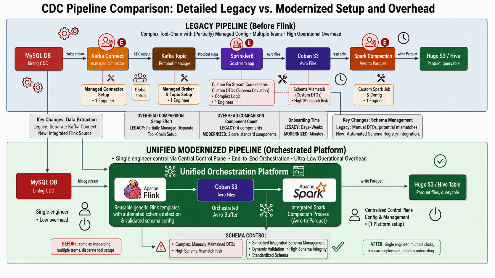
Figure 2. Data ingestion with MySQL CDC to data lake

Self-service Kafka ingestion

The most significant architectural shift in the self-service Kafka ingestion pipeline is the move from manual, fragile schema handling to an automated, resilient system. This comparison highlights the operational pain points eliminated by adopting Flink’s approach.

Legacy Sprinkler approach (manual and static)

  • Static registration and hardcoding: It required manual registration of streams within the Go monorepo and relied on hardcoded mappings in entities.go to convert Protobuf to Avro.
  • Custom dependencies: Avro schema was generated indirectly from custom DTO structs, not directly from the Protobuf definition.
  • Manual schema evolution: Any field change required a multi-step manual process: updating .pb.go and entity files, followed by a manual pipeline rebuild.

New Flink approach (automated and dynamic)

  • Dynamic runtime fetching: Flink pipelines dynamically retrieve the Protobuf schema from Confluent Schema Registry on startup, removing the need for hardcoding and manual stream registration.
  • Reduced operational overhead for schema changes: Schema updates are propagated through the CI pipeline to the Schema Registry, removing the need for hardcoded mapping changes. The Flink pipeline can detect updated schemas and resume from the latest checkpoint after restart, though manual restart intervention is still required.
  • Click-to-query: Engineers can now ingest streaming data from Kafka topics into queryable Hive tables through a few clicks in the Hugo UI. Hugo automatically orchestrates the multi-stage background work, from Flink consumption and S3 writing to Spark compaction, ensuring data is query-optimized and ready for immediate use.
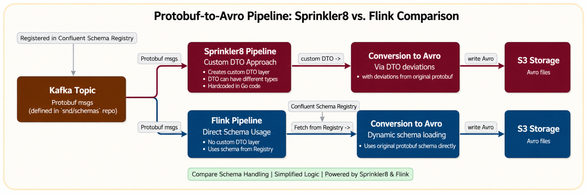
Figure 3. Data ingestion with Kafka to Datalake.

Impact

The platform’s new onboarding workflow has significantly reduced a previously multi-day process to mere minutes, enabling faster iteration and improving overall onboarding efficiency. This dramatic change has fundamentally altered how our teams interact with data.

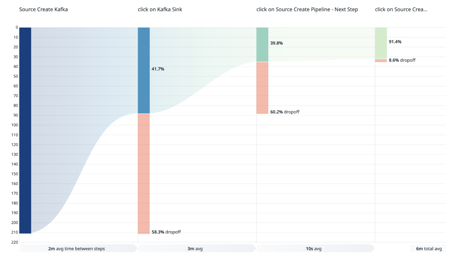
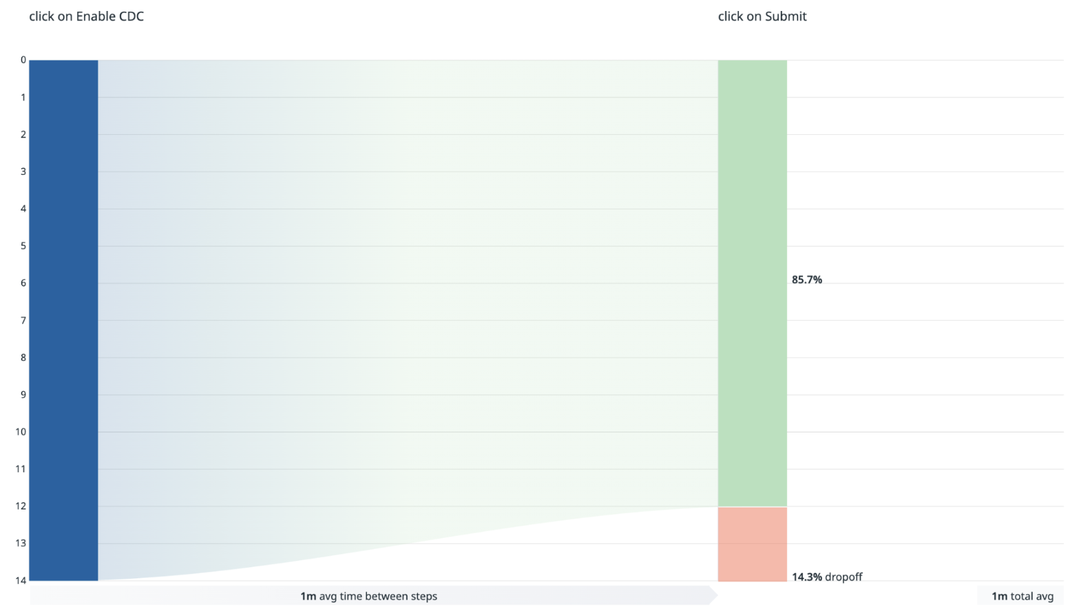
Figure 4. Kafka Flink.
Figure 5. CDC Flink.

The onboarding workflow is intentionally designed with early validation guardrails to proactively surface prerequisite and governance-related issues before pipeline creation proceeds.

  • For Kafka sources, user drop-offs between the “Create Kafka Source” and “Kafka Sink” stages are primarily driven by validation checks such as topic ownership verification and topic activity requirements, for example topics with zero message volume. Additional drop-offs between the “Kafka Sink” and “Create Source Pipeline” stages typically occur when the proposed output table name already exists in the data lake, preventing duplicate table creation.
  • For MySQL sources, drop-offs are mainly associated with unmet database onboarding prerequisites, including credential setup, binlog user configuration, binlog format requirements, and binlog expiration settings.

In addition, the streamlined self-service experience encourages exploratory usage, allowing teams to familiarize themselves with the onboarding workflow and platform capabilities before fully committing to pipeline creation.

Summary

The new architecture engineered a custom automation layer that successfully retired the reliance on Kafka Connect and Sprinkler for the data lake, turning artisanal work into a streamlined, one-click experience. This transformation provides a direct boost to developer productivity.

The key impact metrics are:

  • Onboarding time reduction: The time required to set up data pipelines has been dramatically reduced and is now measured in minutes.
    • Kafka pipelines: approximately 6 minutes.
    • MySQL CDC pipelines: approximately 3 minutes.
  • Adoption: Since the release, the number of new Kafka and CDC pipelines onboarded in the last year is more than the total number of pipelines onboarded in the previous five years.

What’s next

These enhancements are just one step in our broader vision for optimized and self-service data ingestion. Currently, Flink is the default only for Kafka source pipelines. Flink onboarding for MySQL CDC pipelines is impact- and cost-driven. Our strategic roadmap includes:

  • Next-generation formats: We are investigating the adoption of Apache Iceberg as the data lake table format to further improve pipeline SLA and costs, and improve performance.
  • Seamless schema evolution: Schema changes still require some manual effort from pipeline owners, including manually restarting Flink pipelines. In Hugo, we aim to make schema evolution a zero-touch experience by automatically detecting changes, validating compatibility, and updating tables without disruption.

Join us

Grab is Southeast Asia’s leading superapp, serving over 900 cities across eight countries (Cambodia, Indonesia, Malaysia, Myanmar, the Philippines, Singapore, Thailand, and Vietnam). Through a single platform, millions of users access mobility, delivery, and digital financial services, including ride-hailing, food delivery, payments, lending, and digital banking via GXS Bank and GXBank. Founded in 2012, Grab’s mission is to drive Southeast Asia forward by creating economic empowerment for everyone while delivering sustainable financial performance and positive social impact.

Powered by technology and driven by heart, our mission is to drive Southeast Asia forward by creating economic empowerment for everyone. If this mission speaks to you, join our team today!
Enhancing Flink Deployment with Shadow Testing

Post Syndicated from Grab Tech original https://engineering.grab.com/enchancing-flink-shadow-testing

Introduction

Ensuring the reliability of Apache Flink deployments in Grab is crucial for the availability of our business-critical, real-time applications. While all applications are tested in a staging environment before getting promoted to the production environment, there is still a class of issues that can only surface when deploying in the production environment, e.g.:

  • The new version of the application is unable to cope with the volume or the nature of production traffic.
  • The new version of the application is unable to resume from a production checkpoint or savepoint taken by the previous version of the application.
  • Certain environment-specific dependencies or configurations are malfunctioning or misconfigured.

When an application faces such issues upon deployment in production, our in-house deployment system automatically rolls it back after 10 minutes of observation, leading to a downtime of the application for about the same duration.

In this article, we will describe how Grab’s data streaming team (Coban) has enriched the traditional deployment pipeline for Flink applications with a Shadow Testing stage that eliminates this downtime during deployment failures, enhancing the availability of our Flink applications during this critical moment of their lifecycle.

Shadow Testing is a testing technique whereby a new version of an application (Shadow) is deployed in parallel with the current version of the application (Main), but without impacting it. It involves replicating production data to the new version of the application and comparing its behavior with the current version of the application to identify potential issues and regressions.

Architecture overview

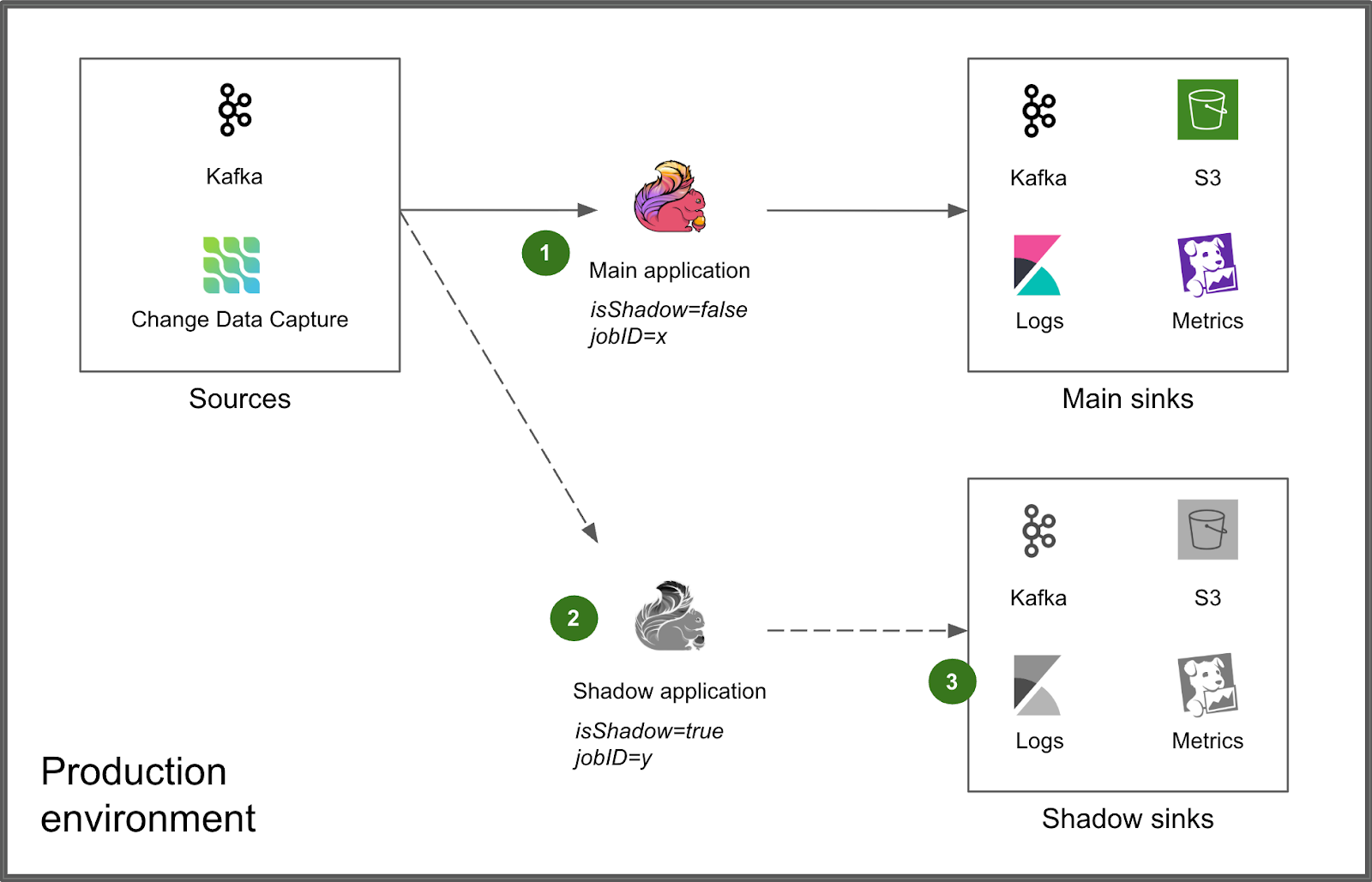
Figure 1. Overall architecture of Shadow Testing.

We integrated Shadow Testing directly into the production environment, alongside the Main application (1). The Shadow application is deployed next to it via the same deployment process (2). An environment variable isShadow=true as well as a distinct jobID are injected for runtime differentiation, enabling the Shadow application to produce its results to distinct, isolated sinks that do not interfere with those of the Main application (3).

Deployment flow

Shadow Testing is embedded within our normal Flink deployment pipeline to make it a seamless experience for the users of our platform.

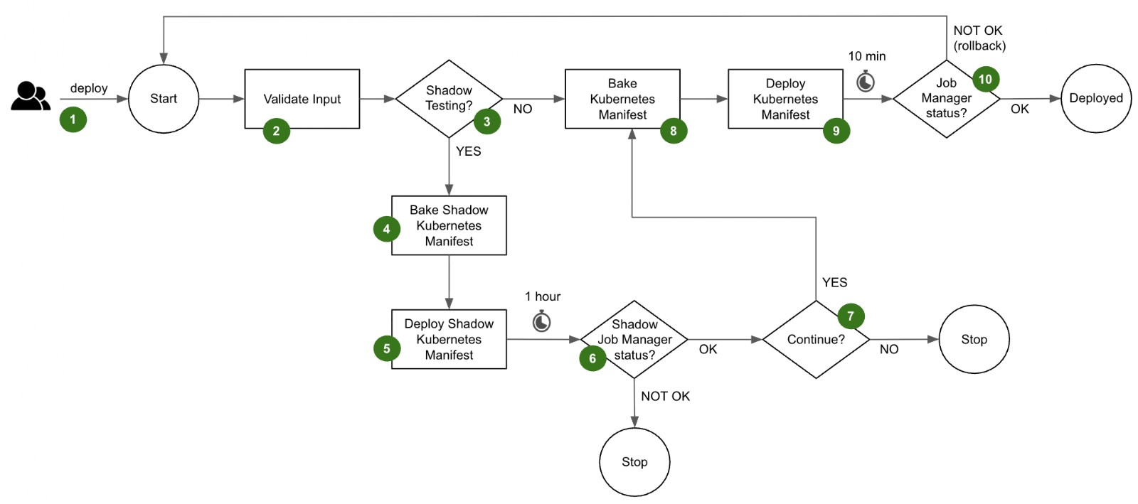
Figure 2. Deployment flow diagram.

The deployment flow is as follows.

  1. A user triggers a deployment of their Flink application in Grab’s in-house deployment tool. At this step, they decide whether they want to enable Shadow Testing for this particular deployment.
  2. The deployment pipeline validates the input parameters provided by the user.
  3. If the user has not opted for Shadow Testing, the deployment flow directly jumps to step 8 and deploys the latest version to the Main application. However, if the user has enabled Shadow Testing, the deployment flow first goes through the Shadow Testing stages described in steps 4 to 7.
  4. The Shadow Kubernetes manifest is baked with its set of distinctive parameters:
    • The application name is prefixed with shadow- which propagates to all the Kubernetes objects that are part of the Shadow application
    • An environment variable isShadow is injected and set to true. It instructs the Shadow application to produce its results to the shadow sinks.
    • A distinct Job ID is attributed
    • The target Kubernetes namespace is overridden with a shadow namespace
  5. The Shadow application is deployed into the shadow Kubernetes namespace.
  6. The Shadow application runs for a configured period of 1 hour by default to reach a steady state. The status of the job manager is monitored to determine the success of the Shadow Testing. If the Shadow application is stable, the Shadow Testing is considered successful.
  7. The user is prompted to continue with the deployment of the Main application.
  8. The Kubernetes manifest of the Main application is baked with its standard parameters and the environment variable isShadow is set to false.
  9. The Main application is deployed in its standard Kubernetes namespace.
  10. After 10 minutes of observation, the deployment pipeline determines if the Main application is healthy by querying the status of its job manager. If it is healthy, the Main application is considered successfully deployed. Otherwise, the deployment pipeline automatically triggers a rollback to the previous version.

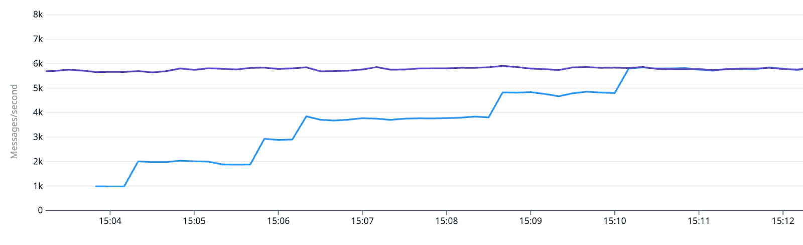
During the deployment, the user can leverage our standard observability stack to monitor the behavior of the Shadow application. For example, in the case of an Apache Kafka sink, they can compare the number of messages produced by the Main and Shadow applications.

Figure 3. Tracking of the Kafka messages.in_rate metric for the respective Kafka sink topics of the Main application (purple) and Shadow application (blue) at the beginning of the Shadow deployment stage.

Besides, our standard Datadog dashboard that comes with each application can conveniently be toggled to view the metrics of the respective Shadow application.

Connector implementation

Our standard sink and source connectors, provided by our platform, ensure the absence of interference with the Main application during Shadow Testing. For example, Kafka source connectors use distinct consumer group IDs, while the various sink connectors direct the data to dedicated shadow sinks.

The Flink application evaluates the isShadow environment variable to set up the connectors at runtime.

if (isShadow){
    // Shadow Testing operation
}
else {
    // Normal operation
}

The following table shows how some typical connectors are dynamically configured if isShadow=true:

Type Connector Dynamic configuration
Source Kafka The consumer group ID for the Shadow application is suffixed with -shadow. This is crucial so as to consume a full copy of the data stream without interfering with the Main application.
Main application: consumerGroup = <application_name>
Shadow application: consumerGroup = <application_name>-shadow
Source Change Data Capture The Server ID range of Debezium is shifted to the next non-overlapping range of the same size. This enables the Shadow application to get a full copy of the database binlog stream without interfering with the Main application. Note that the misleading Server ID naming is because Debezium acts as a pseudo-replica of the database server.
Main application: serverId = 1001-2000
Shadow application: serverId = 2001 – 3000
Sink Kafka The cluster endpoint is replaced with that of a Kafka cluster dedicated to Shadow Testing, set up with auto.create.topics.enable=true and 8h retention.
Main application: brokers = <flink-kafka>:9092
Shadow application: brokers = <flink-kafka-shadow>:9092
Sink S3 The S3 bucket name is replaced with that of a bucket dedicated to Shadow Testing, set up with a 7-day retention lifecycle policy.
Main application: s3://<flink-s3>/<application_name>
Shadow application: s3://<flink-s3-shadow>/<application_name>
Sink Metrics The StatsD prefix configuration is overridden. A shadow. prefix is added.
Main application: flink.<application_name>.<metric_name>
Shadow application: shadow.flink.<application_name>.<metric_name>
Sink Logs The Shadow Kubernetes manifest prefixes the Shadow application name with shadow-. The resulting name becomes available as a field in Kibana, enabling discriminated filtering. This tweak is done at the Kubernetes manifest level, not at the Flink application level.
Main application: app_name = <application_name>
Shadow application: app_name = shadow-<application_name>

Conclusion

Our Shadow Testing framework represents a meaningful step forward in enhancing the reliability of our Flink applications during deployment. By leveraging and enriching the existing components of our platform, we have created a robust system that enables our users to confidently increase their Deployment Frequency and reduce their Change Failure Rate.

What’s next

To drive wider adoption, we intend to support more source and sink connectors. By expanding the range of supported connectors, we could empower teams to leverage Shadow Testing across a broader spectrum of applications.

For connectors that are less frequently used, we consider implementing a no-op approach combined with metrics collection to expose a minimal set of actionable data points.

We will remain focused on making Shadow Testing accessible, scalable, and adaptable to various applications. Stay tuned as we continue to push the boundaries of innovation and deliver solutions that enhance reliability and efficiency across our systems.

Join us

Grab is Southeast Asia’s leading superapp, serving over 900 cities across eight countries (Cambodia, Indonesia, Malaysia, Myanmar, the Philippines, Singapore, Thailand, and Vietnam). Through a single platform, millions of users access mobility, delivery, and digital financial services, including ride-hailing, food delivery, payments, lending, and digital banking via GXS Bank and GXBank. Founded in 2012, Grab’s mission is to drive Southeast Asia forward by creating economic empowerment for everyone while delivering sustainable financial performance and positive social impact.

Powered by technology and driven by heart, our mission is to drive Southeast Asia forward by creating economic empowerment for everyone. If this mission speaks to you, join our team today!
How Grab is accelerating growth with real-time personalization using Customer Data Platform scenarios

Post Syndicated from Grab Tech original https://engineering.grab.com/cdp-scenarios

Introduction

Delivering personalized user experiences in real-time is central to Grab’s strategy, but achieving this at scale poses significant engineering challenges. Grab’s Customer Data Platform (CDP) and Growth team has successfully delivered several real-time campaigns, driving significant business impact through enhanced personalization. These initiatives include high-impact use cases like immediate mall offers, timely traveler recommendations, precise ad retargeting, and proactive interventions during key user journey moments. At the core of these successes is Grab’s CDP, which rapidly deploys advanced real-time personalization via a powerful new capability called “Scenarios.”

About Grab’s CDP

Grab’s CDP is a centralized, reliable repository for user attributes, designed for freshness, governance, and reusability. Built on Grab’s Signal Marketplace framework, the CDP streamlines data management through automation and integration, supporting seamless interactions with internal services and toolings that power marketing, experimentation, ads, Machine Learning (ML) features, and external platforms, including Facebook, Google Ads, and TikTok.

The platform currently manages over 1,000 batch user attributes for Passengers, Drivers, and Merchants, powering diverse use cases from targeted marketing campaigns to operational decision-making across Grab’s entire ecosystem.

The need for real-time personalization

In our current CDP setup, user segments are primarily created for targeting using batch attributes that update once daily. While these batch updates provide valuable historical insights, they are not suitable for scenarios requiring real-time responsiveness. This delay prevents timely engagement with users, particularly when immediate actions can significantly enhance user experiences and conversion rates.

For example, when travelers land at an airport, they immediately benefit from timely suggestions for rides, dining options, or local attractions. Traditional batch processing cannot deliver the agility and responsiveness required for these dynamic scenarios.

Historically, real-time personalization at Grab relied heavily on engineering resources, which resulted in limited scalability and agility. Marketers and product teams often found themselves blocked by engineering bandwidth constraints, restricting experimentation and innovation.

Problem statement

The limitations of Grab’s existing personalization frameworks include:

  • Batch attribute delays: Daily updates are insufficient for scenarios requiring immediate user responses.

  • Limited dynamic enrichment: Difficulties in dynamically integrating real-time events with historical user data, weakens personalization effectiveness.

  • High engineering overhead: Custom solutions require extensive resources, limiting agility and innovation.

To overcome these challenges and support Grab’s vision for comprehensive personalization – including proactive recommendations and assistance – CDP needed robust real-time capabilities.

CDP Scenarios: Real-time personalization made simple

The Scenario feature revolutionizes real-time targeting within the CDP by utilizing user-initiated events, geo-fencing, historical profile data, and on-the-fly predictions. This empowers the business to deliver easy, quick, and flexible personalization without the need for complex engineering efforts.

Scenarios enable innovative use cases such as these:

  • Mall personalization: Real-time personalized offers upon arrival.
  • Traveler assistance: Immediate recommendations at airports or hotels.
  • Ad retargeting: Enhanced real-time ad targeting.
  • Conversion optimization: Timely intervention during user drop-off points.

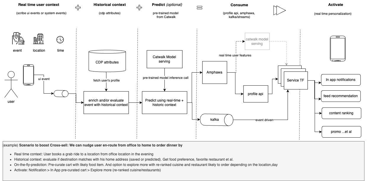
Imagine predicting a user’s intent to drop off at a mall using both real-time and historical context. For instance, when a user books a ride to a mall, factors such as destination, time, cuisine preferences, and past behavior (e.g., affluence level) can help predict whether the user’s purpose is retail therapy, grocery shopping, or dining out. This prediction accounts for elements like time of day, day of the week, and mall location. Grab’s engineering teams can leverage this predicted intent (signal) to offer personalized actions, such as GrabPay discounts for shopping or exclusive dining offers for dinner.

Figure 1. Scenario in CDP.

Key features

  • Event-driven personalization: Real-time Scenarios triggered by Scribe events (Grab’s comprehensive event collection and tracking platform) combined with geo-fencing.
  • Historical context integration: Optionally enrich Scenarios using historical CDP data.
  • Predictive modeling: Deploy pre-trained models for instant user behavior predictions.
  • Self-serve graphical user interface (GUI): Enable marketers to create complex event sequences and validate Scenarios with synthetic data processed through Flink pipelines.
  • Headless application programming interfaces (APIs): Allow programmatic access and management of Scenarios.
Figure 2. Attributes for a scenario in CDP.

Self-serve Scenario creation

We designed an intuitive self-serve UI, embedded within the Grab app, empowering marketers to quickly define and deploy Scenarios. Users can specify event triggers, configure geo-fencing, incorporate historical user attributes, and select predictive models. Marketers can also validate Scenarios using synthetic data before deployment, ensuring accurate and realistic outcomes.

How it works:

  1. Select event triggers: Choose predefined events or define custom intra-session sequences via the GUI.
  2. Configure geo-fencing: Define Scenario activation locations, like airports or malls.
  3. Include historical attributes (optional): Utilize batch attributes from the CDP to enrich Scenarios.
  4. Select predictive models (optional): Train custom classifiers or pick from pre-trained Catwalk models.
  5. Define data sink: Choose between Amphawa (DynamoDB), Kafka, or both; potentially extendable to external destinations (e.g., Appsflyer).
  6. Once configured, metadata synchronizes automatically with our streaming service, and Scenarios become available for real-time consumption within an hour.

Proven impact: Real-world success

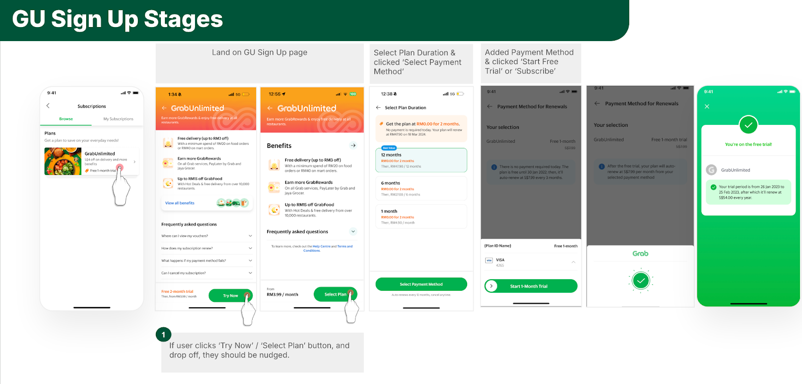
CDP Scenarios are already delivering measurable business results, with over 12 live production implementations. For instance, in a case study addressing Grab Unlimited subscription signup abandonment, we leveraged CDP Scenarios to increase signups by engaging users in real time within 15 minutes of them leaving the signup process.

Figure 3. Grab Unlimited sign-up journey.

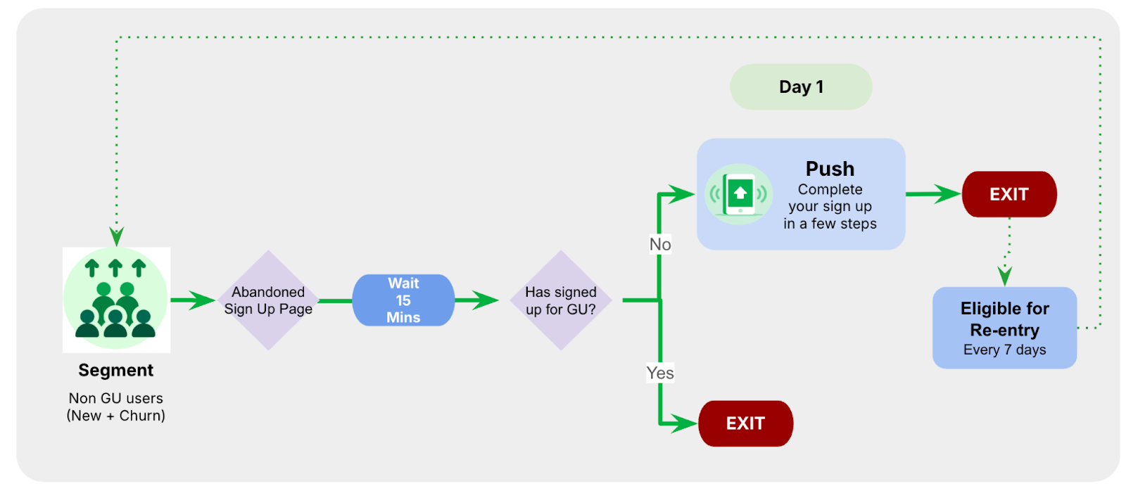
To enhance conversion rates, personalized real-time nudges were deployed through Scenarios. For example, users who started the signup process but failed to complete it within 15 minutes received a follow-up notification, prompting them to finalize their registration.

Figure 4. Scenario flow for Grab Unlimited registration.

This scenario alone achieved more than a 3% uplift in subscriber conversions vs non-real-time acquisition campaigns, demonstrating Scenarios’ potential to significantly boost business outcomes.

Technical architecture: Low latency, high reliability

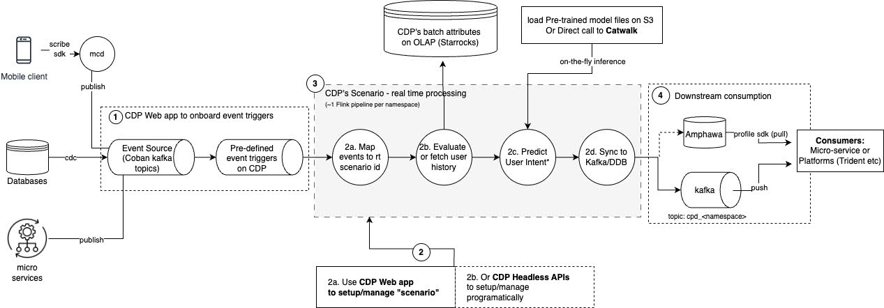
Figure 5. High-level scenario flow. Scenarios are designed for low latency (under 15 seconds) and high reliability.
  1. Event registration: Popular UI events from Scribe are whitelisted and immediately available; custom events are onboarded via the CDP web portal.
  2. Scenario creation: Users configure Scenarios through a user-friendly GUI, defining events, historical contexts, and predictive models.
  3. Real-time Flink processing: Incoming events trigger Scenarios, evaluating user historical data via StarRocks and performing real-time predictions using pre-trained models.
  4. Real-time data sync: Outcomes are synced back to Kafka or Amphawa (Grab’s internal feature store built on AWS DynamoDB), enriching data for use by subsequent services.
  5. Consumption by downstream services: Kafka streams or CDP’s Profile SDK facilitates immediate, personalized user experiences.

Advancing the future of real-time personalization

As we continue to innovate, we are focused on enhancing the capabilities of CDP Scenarios to support more complex and scalable personalization use cases. Here are some key areas of improvement we are exploring:

  • Optimized Scenario sharding for scalable processing: To accommodate the growing number of use cases, we plan to scale and orchestrate our Flink pipeline fleet in a headless manner. This approach will improve system stability and enable seamless management of complex Scenarios across the pipeline.

  • Enhanced signal distribution across multiple destinations: Currently, Scenario outputs are limited to a single topic or sink. To address the increasing diversity of use cases, we aim to expand signal distribution, allowing downstream consumers to access Scenario outcomes through multiple scalable and reliable channels.

  • Advanced scheduling and delayed triggering: While real-time computation of Scenario signals is effective, certain use cases require delayed activation for maximum impact. We are exploring ways to compute signals instantly but trigger actions at scheduled times, such as sending a push notification for booking a return Grab ride based on the average wait time at the drop-off location.

Conclusion: Revolutionizing real-time personalization

The launch of CDP Scenarios represents a significant milestone for Grab, paving the way for scalable, efficient, and user-friendly real-time personalization. Initial successes have demonstrated its immense potential, delivering notable improvements in user engagement and conversion rates. Looking ahead, we are committed to continuously advancing Scenarios by expanding its features, integrations, and applications to further elevate user experiences across the Grab ecosystem.

Join us

Grab is a leading superapp in Southeast Asia, operating across the deliveries, mobility and digital financial services sectors. Serving over 800 cities in eight Southeast Asian countries, Grab enables millions of people everyday to order food or groceries, send packages, hail a ride or taxi, pay for online purchases or access services such as lending and insurance, all through a single app. Grab was founded in 2012 with the mission to drive Southeast Asia forward by creating economic empowerment for everyone. Grab strives to serve a triple bottom line – we aim to simultaneously deliver financial performance for our shareholders and have a positive social impact, which includes economic empowerment for millions of people in the region, while mitigating our environmental footprint.

Powered by technology and driven by heart, our mission is to drive Southeast Asia forward by creating economic empowerment for everyone. If this mission speaks to you, join our team today!

The complete stream processing journey on FlinkSQL

Post Syndicated from Grab Tech original https://engineering.grab.com/the-complete-stream-processing-journey-on-flinksql

Introduction

In the fast-paced world of data analytics, real-time processing has become a necessity. Modern businesses require insights not just quickly, but in real-time to make informed decisions and stay ahead of the competition. Apache Flink has emerged as a powerful tool in this domain, offering state-of-the-art stream processing capabilities. In this blog, we introduce our FlinkSQL interactive solution in accompanying productionising automation, and enhancing our users’ stream processing development journey.

Preface

Last year, we introduced Zeppelin notebooks for Flink, as detailed in our previous post Rethinking Stream Processing: Data Exploration in an effort to enhance data exploration for downstream data users. However, as our use cases evolved over time, we quickly hit a few technical roadblocks.

Zeppelin notebook source code is maintained by a community separate from Flink’s community. As of writing, the latest Flink version supported is 1.17, whilst the latest Flink is already on version 1.20. This discrepancy in version support hinders our Flink upgrading efforts.

Cluster start up time

Our design to spin up a Zeppelin cluster per user on demand invokes a cold start delay, taking roughly around 5 minutes for the notebook to be ready. This delay is not suitable for use cases that require quick insights from production data. We quickly noticed that the user uptake of this solution was not as high as we expected.

Integration challenges

Whilst Zeppelin notebooks were useful for serving individual developers, we experienced difficulty integrating it with other internal platforms. We designed Zeppelin to empower solo data explorers, but other internal platforms like dashboards or automated pipelines needed a way to aggregate data from Kafka and Zeppelin just couldn’t keep up. The notebook setup was too isolated, requiring a workaround to share insights or plug into existing tools. For instance, if a team wanted to pull aggregated real-time metrics into a monitoring system, they had to export data manually, which is far from seamless access that we aimed for.

Introducing FlinkSQL interactive

With those considerations in mind, we decided to swap out our Zeppelin cluster with a shared FlinkSQL gateway cluster. We simplified our solution by removing some features our notebooks offered, focusing only on features that promote data democratisation.

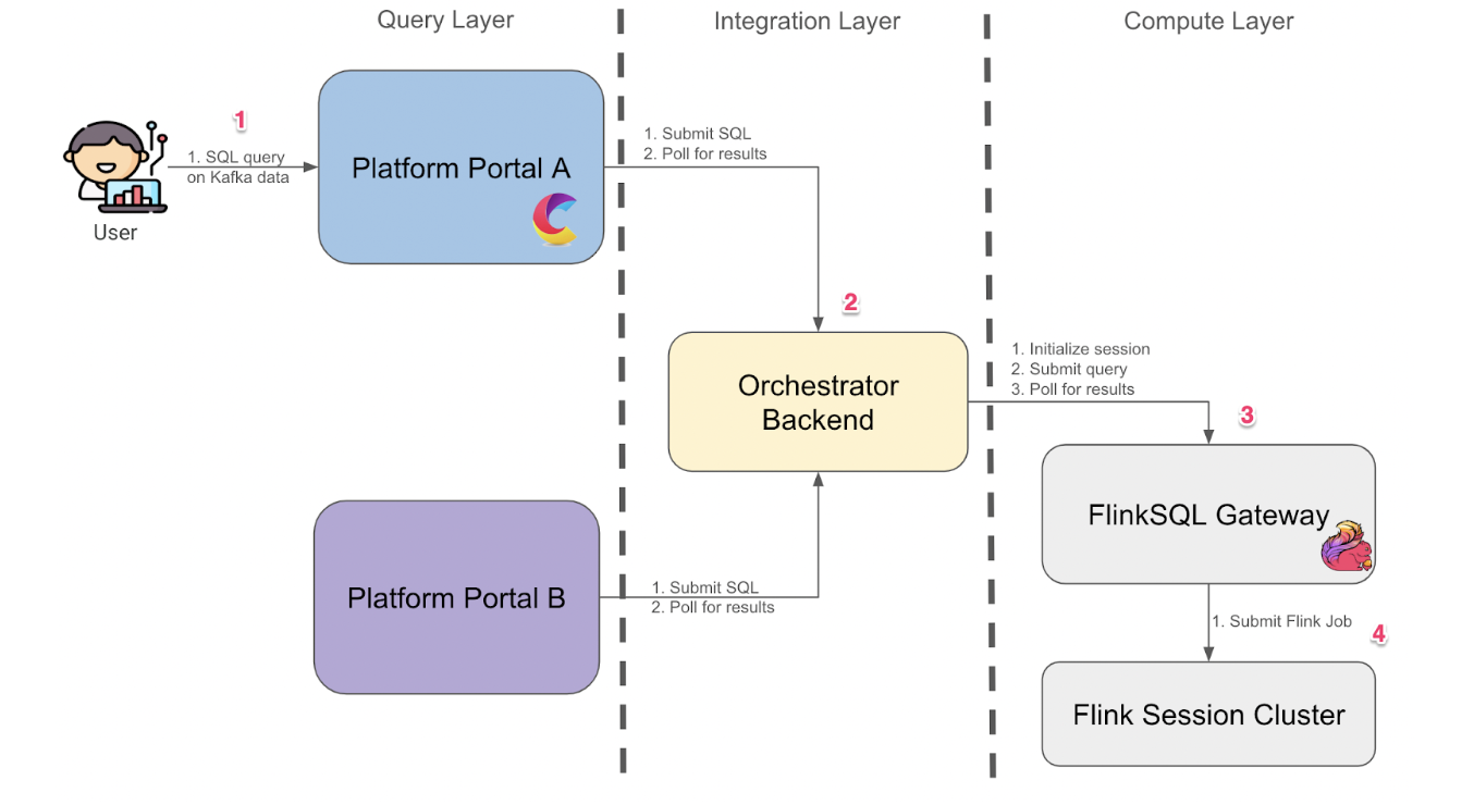
Figure 1: Shared FlinkSQL gateway architecture

We split our solution into 3 layers:

  • Compute layer
  • Integration layer
  • Query layer

Users first interact with our platform portal to submit queries for data from Kafka online store using SQL (1). Upon submission, our backend orchestrator then creates a session for the user (2) and submits the SQL query to our FlinkSQL gateway using their inbuilt REST API (3). The FlinkSQL gateway then packages the SQL query into a Flink job to be submitted to our Flink session cluster (4) before collating its results. The subsequent results would be polled from the query layer to be displayed back to the user.

Compute layer

With FlinkSQL gateway acting as the main compute engine for ad-hoc queries, it is now more straightforward to perform Flink version upgrades along with our solution, since the FlinkSQL gateway is packaged along with the main Flink distribution. We do not need to maintain Flink shims for each version as adapters between the Flink compute cluster and Zeppelin notebook cluster.

Another advantage of using the shared FlinkSQL gateway was the reduced cold start time for each ad-hoc queries. Since all users share the same FlinkSQL cluster instead of having their own Zeppelin cluster, there was no need to wait for cluster startup during initialisation of their sessions. This brought the lead time to the first results displayed down from 5 minutes to 1 minute. There was still lead time involved as the tool provisions task managers on an ad-hoc basis to balance availability of such developer tools and the associated cost.

Integration layer

The Integration layer serves as the glue between the user-facing query layer and the underlying compute layer, ensuring seamless communication and security across our ecosystem. With the shift to a shared FlinkSQL gateway, we recognised the need for an intermediary that could handle authentication, authorisation, orchestration, and integration with internal platforms – all while abstracting the complexities of Flink’s native REST API.

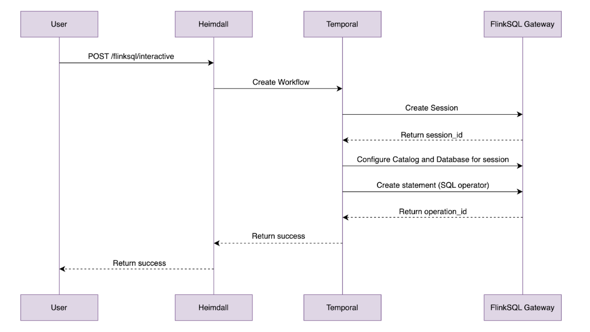
Figure 2: FlinkSQL gateway

The FlinkSQL gateway’s built-in REST API gets the job done for basic query submission, but it falls short in areas like session management, requiring multiple POST requests just to fetch results. To address this, we extended a custom control plane with its own set of REST APIs, layered on top of the gateway.

We then extend these sessions and integrate them to our inhouse authentication and authorisation platform. For each query made, the control plane authenticates the user, spins up lightweight sessions and manages the communication between the caller and the Flink Session Cluster. If you are interested, check out our previous blog post, An elegant platform, for more details on the above mentioned streaming platform and its control plane.

curl --location 'https://example.com/v1/flink/flinksql/interactive' \
--header 'Content-Type: application/json' \
--header 'Authorization: Bearer ...' \
--data '{
    "environment" : "prd",
    "namespace" : "flink",
    "sql" : "SELECT * FROM titanicstream"}'

Example API request for running a FlinkSQL query

The integration layer also caters to B2B needs via our Headless APIs. By exposing the endpoints, developers are able to integrate real-time processing into their own tools. To run a query, programs can simply make a POST request with the SQL query and an operation ID would be returned. This operation ID could then be used in subsequent GET requests to fetch the paginated results of the unbounded query. This setup is ideal for internal platforms that need to query Kafka data programmatically. By abstracting these complexities, it ensures that users, whether individual analysts or internal platforms—can tap into Kafka data without wrestling with Flink’s raw interfaces.

Query layer

We then proceed to pair our APIs developed with an Interactive UI to build a Query layer that serves both human workflows. This is where users meet our platform.

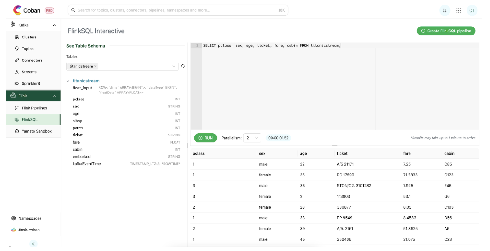
Figure 3: Flink query layer’s user flow

Through our platform portal, users land in a clean SQL editor. We used a Hive Metastore (HMS) catalog that translates Kafka topics into tables. Users don’t need to decode stream internals; they can jump straight into it by simply selecting a table to query on. Once a query is submitted, it is then handled by the integration layer which routes it through the control plane to the gateway. Results are then streamed back, appearing in the UI within one minute, a significant improvement from the five minute Zeppelin cold starts.

This all crystalises into the user flow demonstrated in Figure 3, where we can easily retrieve Titanic data from a Kafka stream with a short command:

SELECT COUNT(*) FROM titanicstream WHERE kafkaEventTime > NOW() - INTERVAL '1' HOUR.

This setup enables a few use cases for our teams, such as:

  • Fraud analysts using the real-time data to debug and spot patterns in fraudulent transactions.
  • Data scientists querying live signals to validate their prediction models.
  • Engineers validating the messages sent from their system to confirm they are properly structured and accurately delivered.

Productionising FlinkSQL

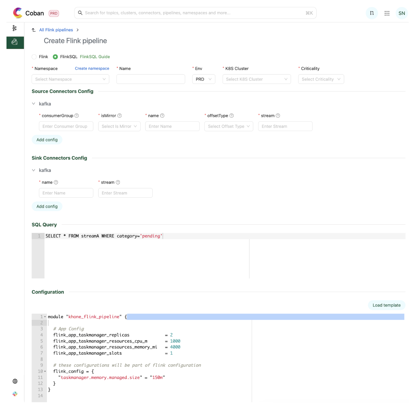
With data being democratised, we see more users building use cases around our online data store and utilising the above tools to build new stream processing pipelines expressed as SQL queries. To simplify the last step of the software development lifecycle of deployment, we have also developed a tool to create a configuration based stream processing pipeline, with the business logic expressed as a SQL statement.

Figure 4: Portal for FlinkSQL pipeline creation

We host connectors for users to connect to other platforms within Grab, such as Kafka and our internal feature stores. Users could simply use them off-the-shelf and configure according to their needs before deploying their stream processing pipeline.

Users would then proceed to submit their streaming logic as a SQL statement. In the example illustrated in the diagram, the logic expressed is a simple filter on a Kafka stream for sinking the filtered events into a separate Kafka stream.

Users have the ability to then define the parallelism and associated resources they want to run their Flink jobs with. Upon submission, the associated resources would be provisioned and the Flink pipeline would be automatically deployed. Behind the scenes, we manage the application JAR file that is being used to run the job that dynamically parses these configurations and translates them into a proper Flink job graph to be submitted to the Flink cluster.

Within 10 minutes, users would have completed deploying their stream processing pipeline to production.

Conclusion

With our full suite of solutions for low code development via FlinkSQL, from exploration and design, to development and then deployment, we have simplified the journey for developing business use cases off online streaming stores. By offering both a user-friendly interface for low-code users and a robust API for developers, these tools empower businesses to harness the full potential of real-time data processing. Whether you are a data analyst looking for quick insights or a developer integrating real-time analytics into your applications, our tools are able to lower the barrier of entry to utilising real-time data.

After we released these solutions, we quickly saw an uptick in pipelines created as well as the number of interactive queries fired. This result was encouraging and we hope that this would gradually bring upon a paradigm shift, enabling Grab to make data-driven operational decisions on real-time signals, empowering us with the ability to react to ever-changing market conditions in the most efficient manner.

Join us

Grab is a leading superapp in Southeast Asia, operating across the deliveries, mobility and digital financial services sectors. Serving over 800 cities in eight Southeast Asian countries, Grab enables millions of people everyday to order food or groceries, send packages, hail a ride or taxi, pay for online purchases or access services such as lending and insurance, all through a single app. Grab was founded in 2012 with the mission to drive Southeast Asia forward by creating economic empowerment for everyone. Grab strives to serve a triple bottom line – we aim to simultaneously deliver financial performance for our shareholders and have a positive social impact, which includes economic empowerment for millions of people in the region, while mitigating our environmental footprint.

Powered by technology and driven by heart, our mission is to drive Southeast Asia forward by creating economic empowerment for everyone. If this mission speaks to you, join our team today!