All posts by Bryan Berezdivin

Ingesting Automotive Sensor Data using DXC RoboticDrive Ingestor on AWS

Post Syndicated from Bryan Berezdivin original https://aws.amazon.com/blogs/architecture/ingesting-automotive-sensor-data-using-dxc-roboticdrive-ingestor-on-aws/

This post was co-written by Pawel Kowalski, a Technical Product Manager for DXC RoboticDrive and Dr. Max Böhm, a software and systems architect and DXC Distinguished Engineer.

To build the first fully autonomous vehicle, L5 standard per SAE, auto-manufacturers collected sensor data from test vehicle fleets across the globe in their testing facilities and driving circuits. It wasn’t easy collecting, ingesting and managing massive amounts of data, and that’s before it’s used for any meaningful processing, and training the AI self-driving algorithms. In this blog post, we outline a solution using DCX RoboticDrive Ingestor to address the following challenges faced by automotive original equipment manufacturers (OEMs) when ingesting sensor data from the car to the data lake:

  • Each test drive alone can gather hundreds of terabytes of data per fleet. A few vehicles doing test fleets can produce petabyte(s) worth of data in a day.
  • Vehicles collect data from all the sensors into local storage with fast disks. Disks must offload data to a buffer station and then to a data lake as soon as possible to be reused in the test drives.
  • Data is stored in binary file formats like ROSbag, ADTF or MDF4, that are difficult to read for any pre-ingest checks and security scans.
  • On-premises (ingest location) to Cloud data ingestion requires a hybrid solution with reliable connectivity to the cloud.
  • Ingesting process depositing files into a data lake without organizing them first can cause discovery and read performance issues later in the analytics phase.
  • Orchestrating and scaling an ingest solution can involve several steps, such as copy, security scans, metadata extraction, anonymization, annotation, and more.

Overview of the RoboticDrive Ingestor solution

The DXC RoboticDrive Ingestor (RDI) solution addresses the core requirements as follows:

  • Cloud ready:  Implements a recommended architectural pattern where data from globally located logger copy stations are ingested into the cloud data lake in one or more AWS Regions over AWS Direct Connect or Site-to-Site VPN connections.
  • Scalable: Runs multiple steps as defined in an Ingest Pipeline, containerized on Amazon EKS based Amazon EC2 compute nodes that can auto-scale horizontally and vertically on AWS. Steps can be for example, Virus Scan, Copy to Amazon S3, Quality Check, Metadata Extraction, and others.
  • Performant: Uses the Apache Spark-based DXC RoboticDrive Analyzer component to process large amounts of sensor data files efficiently in parallel, which will be described in a future blog post. Analyzer can read and processes native automotive file formats, extract and prepare metadata, and populate metadata into the DXC RoboticDrive Meta Data Store. The maximum throughput of network and disk is leveraged and data files are placed on the data lake following a hierarchical prefix domain model, that aligns with the best practices around S3 performance.
  • Operations ready: Containerized deployment, custom monitoring UI, visual workflow management with MWAA, Amazon CloudWatch based monitoring for virtual infrastructure and cloud native services.
  • Modular: Programmatically add or customize steps into the managed Ingest Pipeline DAG, defined in Amazon Managed Workflows for Apache Airflow (MWAA).
  • Security: IAM based access policy and technical roles, Amazon Cognito based UI authentication, virus scan, and an optional data anonymization step.

The ingest pipeline copies new files to S3 followed by user configurable steps, such as Virus Scan or Integrity Checks. When new files have been uploaded, cloud native S3 event notifications generate messages in an Amazon SQS queue. These are then consumed by serverless AWS Lambda functions or by containerized workloads in the EKS cluster, to asynchronously perform metadata extraction steps.

Walkthrough

There are two main areas of the ingest solution:

  1. On-Premises devices – these are dedicated copy stations in the automotive OEM’s data center where data cartridges are physically connected. Copy stations are easily configurable devices that automatically mount inserted data cartridges and share its content via NFS. At the end of the mounting process, they call an HTTP post API to trigger the ingest process.
  2. Managed Ingest Pipeline – this is a Managed service in the cloud to orchestrate the ingest process. As soon as a cartridge is inserted into the Copy Station, mounted and shared via NFS, the ingest process can be started.
Figure 1 - Architecture showing the DXC RoboticDrive Ingestor (RDI) solution

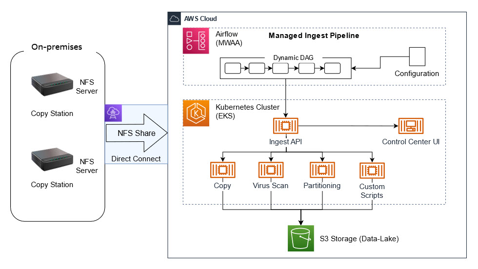
Figure 1 – Architecture showing the DXC RoboticDrive Ingestor (RDI) solution

Depending on the customer’s requirements, the ingest process may differ. It can be easily modified using predefined Docker images. A configuration file defines what features from the Ingest stack should be used. It can be a simple copy from the source to the cloud but we can easily extend it with additional steps, such as a virus scan, special data partitioning, data quality checks on even scripts provided by the automotive OEM.

The ingest process is orchestrated by a dedicated MWAA pipeline built dynamically from the configuration file. We can easily track the progress, see the logs and, if required, stop or restart the process. Progress is tracked at a detailed level, including the number and volume of data uploaded, remaining files, estimated finish time, and ingest summary, all visualized in a dedicated ingest UI.

Prerequisites

Ingest pipeline

To build an MWAA pipeline, we need to choose from prebuilt components of the ingestor and add them into the JSON configuration, which is stored in an Airflow variable:

{
    "tasks" : [
        {
            "name" : "Virus_Scan",
            "type" : "copy",
            "srcDir" : "file:///mnt/ingestor/CopyStation1/",
            "quarantineDir" : "s3a://k8s-ingestor/CopyStation1/quarantine/”
        },
        {
            "name" : "Copy_to_S3",
            "type" : "copy",
            "srcDir" : "file:///mnt/ingestor/car01/test.txt",
            "dstDir" : "s3a://k8s-ingestor/copy_dest/",
            "integrity_check" : false
        },
        {
            "name" : "Quality_Check",
            "type" : "copy",
            "srcDir" : "file:///mnt/ingestor/car01/test.txt",
            "InvalidFilesDir" : "s3a://k8s-ingestor/CopyStation1/invalid/",
        }
    ]
}

The final ingest pipeline, a Directed Acyclic Graph (DAG), is built automatically from the configuration and changes are visible within seconds:

Figure 2 - Screenshot showing the final ingest pipeline, a Directed Acyclic Graph (DAG)

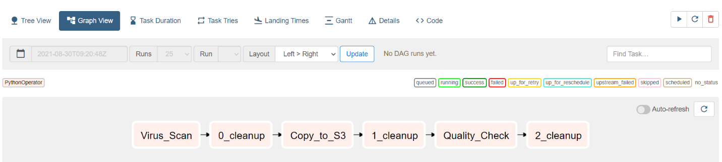
Figure 2 – Screenshot showing the final ingest pipeline, a Directed Acyclic Graph (DAG)

If required, external tools or processes can also call ingest components using the Ingest API, which is shown in the following screenshot:

Figure 3 - Screenshot showing a tool being used to call ingest components using the Ingest API

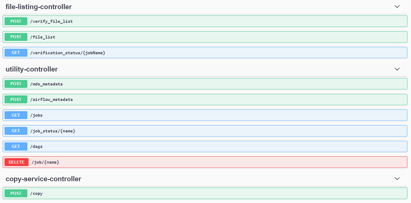
Figure 3 – Screenshot showing a tool being used to call ingest components using the Ingest API

The usual ingest process consists of the following steps:

  1. Ingest data source (cartridge) into the Copy Station

2. Wait for Copy Station to report proper cartridge mounting. In case a dedicated device (Copy Station) is not used, and you want to use an external disc as your data source, it can be mounted manually:

mount -o ro /dev/sda /media/disc

Here, /dev/sda is the disc containing your data and /media/disc is the mountpoint, which must also be added to /etc/exports.

3. Every time the MWAA ingest pipeline (DAG) is triggered, a Kubernetes job is created through a Helm template and Helm values which add the above data source as a persistent volume (PV) mount inside the job.

Helm template is as follows:

apiVersion: v1

kind: PersistentVolume

metadata:

 name: {{ .name }}

 namespace: {{ .Values.namespace }}

spec:

 capacity:

  storage: {{ .storage }}

 accessModes:

  - {{ .accessModes }}

nfs:

 server: {{ .server }}

 path: {{ .path }}

Helm values:

name: "YourResourceName"

server: 10.1.1.44

path: "/cardata"

mountPath: "/media/disc"

storage: 100Mi

accessModes: ReadOnlyMany

4.  Trigger ingest manually from MWAA UI – this can also be automatically triggered from a Copy Station by calling MWAA API:

curl -X POST "https://roboticdrive/api/v1/dags/ingest_dag/dagRuns" -H "accept: application/json" -H "Content-Type: application/json" -d "{\"dag_run_id\":\"IngestDAG\"}"

5.  Watch ingest progress – this can be omitted as the ingest results, such as success, failure, can be notified by email or reported to a ticketing system.

6.  Once successfully uploaded, turn off the Copy Station manually or it can be the last task of a flow in the following ingest DAG:

(…)

def ssh_operator(task_identifier: str, cmd: str):

    return SSHOperator(task_id=task_identifier,

                       command=cmd + ' ',

                       remote_host=CopyStation,

                       ssh_hook=sshHook,

                       trigger_rule=TriggerRule.NONE_FAILED,

                       do_xcom_push=True,

                       dag= IngestDAG)

host_shutdown = ssh_operator(task_identifier='host_shutdown', \

                             cmd='sudo shutdown –h +5 &')

When launched, you can track the progress and basic KPIs on the Monitoring UI:

Figure 5 - Screenshot basic KPIs on the Monitoring UI

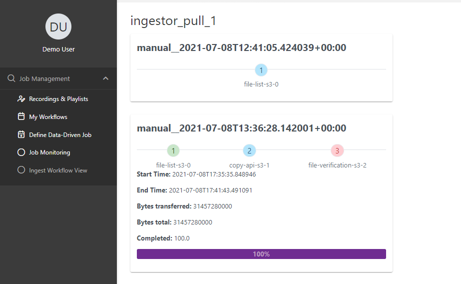
Figure 4 – Screenshot basic KPIs on the Monitoring UI

Conclusion

In this blog post, we showed how to set up the DXC RoboticDrive Ingestor. This solution was designed to overcome several data ingestion challenges and resulted in the following positive results:

  • Time-to-Analyze KPI decreased by 30% in our tests, local offload steps become obsolete, and data offloaded from cars were accessible on a globally accessible data-lake (S3) for further processing and analysis.
  • MWAA integrated with EKS made the solution flexible, fault tolerant, as well as easy to manage and maintain.
  • Autoscaling the compute capacity as needed for any pre-processing steps within ingestion, helped with boosting performance and productivity.
  • On-premises to AWS cloud connectivity options provided flexibility in configuring and scaling (up and down), and provides optimal performance and bandwidth.

We hope you found this solution insightful and look forward to hearing your feedback in the comments!

Dr. Max Böhm

Dr. Max Böhm

Dr. Max Böhm is a software and systems architect and DXC Distinguished Engineer with over 20 years’ experience in the IT industry and 9 years of research and teaching at universities. He advises customers across industries on their digital journeys, and has created innovative solutions, including real-time management views for global IT infrastructures and data correlation tools that simplify consumption-based billing. He currently works as a solution architect for DXC Robotic Drive. Max has authored or co-authored over 20 research papers and four patents. He has participated in key industry-research collaborations including projects at CERN.

Pawel Kowalski

Pawel Kowalski

Pawel Kowalski is a Technical Product Manager for DXC RoboticDrive where he leads the Data Value Services stream. His current area of focus is to drive solution development for large-scale (PB) end-to-end data ingestion use cases, ensuring performance and reliability. With over 10 years of experience in Big Data Analytics & Business Intelligence, Pawel has designed and delivered numerous customer tailored solutions.

Field Notes: Implementing Hardware-in-the-Loop for Autonomous Driving Development on AWS

Post Syndicated from Bryan Berezdivin original https://aws.amazon.com/blogs/architecture/field-notes-implementing-hardware-in-the-loop-for-autonomous-driving-development-on-aws/

Automotive customers use AWS as their platform for advanced driving assistance systems (ADAS) and autonomous driving (AD) development to accelerate their development cycles and experience faster time-to-market.  In the blog post, Autonomous Vehicle and ADAS development on AWS Part 1: Achieving Scale, we illustrated how software in the loop (SiL) and hardware in the loop (HiL) simulations are part of the workflow used to develop and validate safe AD and ADAS functionality. In this post, I run through some of the more common questions and patterns for implementing HiL on AWS, while looking at some of the differences from running your development all on-premises.

HiL simulations leverage test drive data and derived synthetic data to develop and validate various functions in the AD software stack.  Test drive log data is ingested and stored in Amazon S3 for use for HiL simulations in parallel with other AD development workloads including visualization, processing, labeling, analysis, and model and algorithm development.

As such, we see customers exist in a hybrid context with their HiL workloads running on-premises to support customized equipment. For ADAS and ADS customers, this poses a few questions and considerations:

  • What are the recommendations to deploy HiL for AD on AWS?
  • How is this different from what customers were used to on-premises?

For hybrid customers, there are assumptions and misconceptions:

  • Do I need to replicate the test drive data locally, and if so, what are the considerations and consequences?

For the purposes of brevity, the remainder of this blog post will use the term AD development to encompass ADAS and AD unless specifically called out.

HiL Building Blocks

Simulations and validations make up an important aspect of AD development. According to Rand’s analysis, there is a need to demonstrate safe driving on billions of miles for an autonomous vehicle to have a lower failure rate than a human driver. While this analysis is statistically derived for fully autonomous driving (SAE Level 5), it demonstrates a need for further validation on millions of miles. This pattern is reflected in most ADAS and AD development projects, where software in the loop (SiL) and HiL are used for verification and validation.

The following diagram is an illustration of the ISO 26262 V-Model, a product development approach for matching requirements with corresponding tests, where HiL simulation is required for much of system level testing and validation phases on the right side of the overlaid V-Model.

Figure 1: V-Model as defined by ISO-26262

Figure 1: V-Model as defined by ISO-26262

HiL simulations require a few key elements. The main component is the device under test (DUT), such as one or more electronic control units (ECUs) running the AD software stack. HiL simulations allow customers to put the device under test (DUT) under the rigor of real-world signals found in a vehicle. By providing more accurate environments and scenarios for the DUT, it can be fine-tuned for key performance indicators (KPIs) such as power utilization, response time, and accuracy.

The DUT is connected to a “HIL Rig,” a high performance server with multiple expansion boards to connect to various components of the AD system. The various interfaces are identified in Figure 2:  High Level Hardware-in-the-loop (HiL) System and Interfaces and include Controller Area Network (CAN), Automotive Ethernet, Low Voltage Differential Signal (LVDS), and PCIExpress. These interfaces emulate the vehicular topology for testing purposes and allow system level validation of the DUT.

The HiL Rigs and the corresponding software tooling are offered by companies like Elektrobit, dSpace, National Instruments, and Opal-RT. The HiL systems facilitate time synchronized inputs and outputs to the DUT and measures system performance. These solutions have optimizations for large-scale operations aligned with faster validation cycles for customers. This latter point is relevant when a project requires validation across a large number of miles. Elektrobit provides the ability to orchestrate and deploy large HiL server farms that can be deployed to work in parallel. The larger server farms allow parallel HiL simulations to reduce the time to validate thousands of miles of drive time and assess the key performance indicators (KPIs) for the feature sets. Results can be acted on more quickly and reduce the overall development time.

Figure 2: High Level Hardware-in-the-loop (HiL) System and Interfaces

Figure 2: High Level Hardware-in-the-loop (HiL) System and Interfaces

The HIL system loads sensor data derived from test drive logs. These logs vary in format, but often are captured and stored as MDF4, ADTF, rosbag, or other data logger proprietary formats. These are then processed for HIL simulations to implement open-loop and closed-loop simulations.

  • Open loop simulations refer to replay of log data from test drives.
  • Closed-loop simulations rely on the behavior of the system as inputs vary based on new outputs of the simulation.

Both open loop and closed loop simulations are part of autonomous driving development, but open-loop simulations require the largest datasets (multiple petabytes on average) due to reliance on the log data from test drives making them a primary concern for deploying HiL in a hybrid manner.

Overview of Solution

Architectures for supporting HIL simulations with AWS for AD development vary based primarily on the networking available at HiL locations. A common pattern for AWS customers is to have the HiL systems directly interfacing with Amazon S3 over high-bandwidth network links leveraging AWS Direct Connect. This is the simplest approach to deploying HiL and avoids hybrid data management of the petabytes of data in Amazon S3 to a local storage system.

AWS Direct Connect provides customers options to deploy their HIL rigs at their data center or in AWS colocation facilities with low latency connections. AWS has the largest number of Direct Connection locations and points-of-presence (POPs) to enable low latency connectivity to any of the >24 AWS Regions. The following diagram illustrates a reference architecture leveraging a direct interface from the HiL systems and Amazon S3.

Figure 3 : Reference Architecture for Hardware-in-the-Loop (HiL) Direct to Amazon S3

As shown in Figure 3, we illustrate the common interfaces, topology, and AWS services used for autonomous driving customers.

  • Amazon S3 is used to store and analyze the test drive logs used by the HiL simulations and also the results from the simulation runs for further analysis.
  • Metadata of test drive data is populated in various database and analytics services, referred to as the data catalogues, with metadata crawlers and processing pipelines that extract from the drive log and test result data on Amazon S3.
  • The data catalogues provide flexible search interfaces for developers and validation engineers or advanced analytics tools. These systems provide keyword search in Amazon Elasticsearch or SQL queries in Amazon Redshift or Amazon RDS and noSQL interfaces using Amazon DynamoDB. Amazon Partner Network solutions for these database and analysis tools are common as well, such as those in AWS Marketplace.
  • Validation engineer, data scientists, or developers use these data catalogues to find scenarios for testing. These personas also use the HiL management interfaces to configure and orchestrate the HiL simulation runs on the scenarios identified and ensure traceability.
  • HiL management systems control the HiL Rigs that interface to the DUT and implement the HiL simulations using the test drive logs. The HiL management system then writes results back to S3 for further analysis via various tool chains.

A common question AWS customers have is how to determine an optimal hybrid architecture using this approach. The primary factors are properly sized network links to accommodate data sets used by the HiL simulations as well as low latency network links between Amazon S3 and the HiL rigs. As a result, a key factor is ensuring use of an AWS region for your AWS storage that is in close proximity to your HiL testing site(s).

Based on current HiL implementations, open-loop simulations can sustain latencies of 30-50 ms RTT. AWS has numerous AWS Direct Connect locations in co-location facilities with latencies <5ms RTT. Sizing for these network links can be calculated based on the expected dataset sizes and the interval of time targeted for simulation run. We show a basic formula used for network sizing.

Average_Throughput (Gbps) = Average_Dataset_Size(GB)*8 / Time_Interval (seconds)

As an example, for a scenario where an average of 20PB is needed by the HIL rig every 2 weeks, we require ~200Gbps for the AWS Direct Connect bandwidth.

Figure 4 shows an example of a high-level architecture supported by Elektrobit with multiple EB 9101 test racks grouped together. This architecture supports multiple ECUs to be tested at once, leveraging drive log data in Amazon S3. This system is controlled with a central management software that allows optimal orchestration to keep the Elektrobit HiL system running optimally.

Use cases include:

  • The automated replay of all relevant sensor data with high time precision to ECU
  • Capture of ECU responses including debug data
  • Integration of customer components inside the HiL rack for visualization or post-processing.

Another common question from AWS customers is whether this architecture is supported for their HiL implementation. Many HiL providers are adding AWS functionality to their software and hardware stacks in response to customers transitioning to cloud for the development platforms.  Some vendors still require Amazon S3 as a supported interface in their HiL Rigs. The work needed to accommodate Amazon S3 is usually a small level of effort for any developer by using Amazon SDKs on the HiL rig software stack. If there is a project where this is needed, contact the AWS account teams and your HiL vendors to ensure a successful and cost efficient project implementation.

Figure 4: Elektrobit HiL Architecture with AWS

Figure 4: Elektrobit HiL Architecture with AWS

An alternative HiL solution shown in Figure 5 includes Amazon S3 as the primary storage for drive log data and the scale out NAS storage system is located on-premises operating as a cache for the HIL rigs. This is common when the networking options at the HIL site are limited in bandwidth or latency to handle the target datasets and time windows.

AWS customers calculate the size of the cache to transfer the entire dataset over the intended time interval. Following is a simple calculation to demonstrate this.

Cache_Size(GB) = Average_Dataset_Size(GB) - Average_Throughput (Gbps) /8 * Time_Interval (seconds)

In this example, a customer has 40 Gbps AWS Direct Connect available and a 10PB dataset needed for HIL simulations every 2 weeks. Using the preceding formula there is a need for local cache of four PB capable of high read-rates.

Figure 5: Reference Architecture for Hardware-in-the Loop (HiL) with Local Cache to Amazon S3

Figure 5: Reference Architecture for Hardware-in-the Loop (HiL) with Local Cache to Amazon S3

In this hybrid architecture there is a need to orchestrate the data movement in line with the needs of the HIL simulation data set. This requires third party software generally or built in functionality into workflow orchestration tools like Apache Airflow. At CES 2019, Dell EMC and AWS illustrated a solution for this hybrid architecture documented in this short solution brief using Isilon as the scale out NAS storage system and DataIQ as the data movement and orchestration mechanism.

Any of these architectures can be cost-optimized, and AWS has programs and pricing options for Amazon Direct Connect as well as the other AWS services involved. There are Enterprise Agreements and Migration Acceleration Programs (MAP)  in line with the holistic AD development platform needs, that reduce the costs for hybrid architecture functionality needed in the HiL solutions. One common need is support for AWS Direct Connect “flat rate” pricing option to accommodate the data transfer out (DTO) needs for the HiL workload. If you need details on these programs for your AD development project, contact your AWS account team.

Conclusion

In this blog post, we discussed two common architectural patterns for supporting HiL simulations for ADAS and Autonomous Driving development. These help customers decide on the right networking, storage, and hybrid topologies for these systems.

HiL systems directly interfacing with Amazon S3 is the most common pattern as you see with Elektrobit HiL solutions, but for customers with limited network links the use of a local cache is an option. Autonomous driving customers looking to increase velocity in their SAE Level 2-5 development programs with HiL simulations have achieved success with AWS as the development platform using these patterns. AWS has a team dedicated to autonomous driving, so contact your AWS account team to get a more prescriptive solution for your HiL or related ADAS and AD development needs.

Also, check out the Automotive issue of the AWS Architecture Monthly Magazine.

Field Notes provides hands-on technical guidance from AWS Solutions Architects, consultants, and technical account managers, based on their experiences in the field solving real-world business problems for customers.