Tag Archives: Field Notes

Field Notes: Integrating Active Directory Federation Service with AWS Single Sign-On

Post Syndicated from Shirin Bano original https://aws.amazon.com/blogs/architecture/field-notes-integrating-active-directory-federation-service-with-aws-single-sign-on/

Enterprises use Active Directory Federation Services (AD FS) with single sign-on, to solve operational and security challenges by allowing the usage of a single set of credentials for multiple applications. This improves the user experience and helps manage access to the applications in a centralized way.

AWS offers a native cloud-based single sign-on solution called AWS Single Sign-On (AWS SSO). This service helps centrally manage SSO access and user permissions to all the AWS accounts and cloud applications. AWS SSO supports identity federation with SAML 2.0, allowing integration with AD FS solutions. This helps enterprises migrate to AWS, who have a hybrid environment with on-premises AD FS and need access to AWS accounts and cloud applications. Users can sign in to the AWS SSO portal with their corporate credentials thus reducing the admin overhead of maintaining separate credentials on AWS SSO.

Note: you can skip AD FS and connect your Active Directory to AWS SSO directly, instead. This gives you a simpler integration and with AD FS, enables you to use WebAuthn and TOTP MFA, and gives you a free and easy SAML IdP for apps. However, if you have specific constraints that require using AD FS, this blog will help you configure that.

This section explains the authentication flow with AD FS and AWS SSO integration. You can use Identity Provider (AD FS) initiated or Service Provider (AWS SSO) initiated authentication methods.

Following are the steps involved for both Identity Provider (IdP) and Service Provider (SP) initiated authentication methods:

1. IdP Initiated Authentication Flow 

Authentication Flow:

You access the SSO user-portal URL. The authentication flow depends on how you initiate the login request. There are 2 methods in which you can access the SSO user-portal.

IdP (AD FS) Initiated Authentication Method

1.a. This method is followed when users access the AD FS SSO user-portal URL. Some organizations prefer this method when they have a federation system built into their on-premises network and they start using AWS Services. The AWS SSO and AD FS integration allows them to continue using the AD FS user-portal URL, and to login even after they move to AWS.

The following diagram outlines the architecture for the IdP (AD FS) Initiated Authentication Method.

AD FS Reference Architecture

2. SP Initiated Authentication Flow

The following diagram outlines the architecture for an SP Initiated Authentication flow.

SP Initiated Authentication Flow

SP (AWS SSO) Initiated Authentication Method

  1. This method is followed when users access the AWS SSO user-portal URL, for example, https://d-12345c789.awsapps.com/start.
  2. Once the request arrives at the AWS SSO endpoint, it is redirected to the AD FS user-portal URL.
  3. The user then goes to the AD FS user-portal URL, for example, https://acmecorp.com/adfs/ls after which the traffic flow is similar to the IdP Initiated Authentication method.
  4. You are asked to enter the username and password after which it is authenticated against the Active Directory.
  5. You receive a SAML assertion, as an authentication response, from AD FS. The assertion identifies you and includes attributes about you as the user.
  6. You are redirected to the AWS SSO endpoint and it posts the SAML Assertion.
  7. AWS SSO endpoint calls the AssumeRoleWithSAML API to the STS service for temporary security credentials on your behalf. This creates a console sign-in URL that uses those credentials.
  8. AWS sends the sign-in URL back to you as a redirect. You are then re-directed to the AWS SSO Application page, where you can choose the account to log into or the cloud/custom application to use.

Process to Integrate AD FS with AWS SSO

In this section, we show the configurations needed to establish a trust between AD FS and AWS SSO. This allows you to log into AWS accounts using the credentials configured in AD FS.

Step 1: Build SAML Trust Relationship between AD FS and AWS SSO

  1. Get AWS SSO SAML metadata information.
  2. Log into the AWS account where you have configured AWS SSO. On the AWS SSO console, select Dashboard and then Choose your identity source.
  3. On the settings page, select Change, next to the Identity source.
  4. Change the identity source and select External identity provider.
  5. Under Service provider metadata, select show individual metadata information.
  6. Make a note of AWS SSO Sign-in URL, AWS SSO ACS URL, and AWS SSO issuer URL, as these will be used to configure AWS SSO as the relying party in the AD FS settings.
Service Provider metadata

Figure 1 – Service Provider metadata

Add AWS SSO as a Relying Party in AD FS

  1. Go to AD FS Management from the Tools menu in the Server Manager.
  2. Select Add Relying Party Trust.
  3. For Add Relying Party Trust Wizard, choose Claims aware and select Start.
  4. For Select Data Source, select Enter data about the relying party manually.
  5. For Specify Display Name add a user-friendly name for example – AWS SSO.
  6. For Configure URL, select the option Enable support for the SAML 2.0 WebSSO protocol.
  7. Enter the value for AWS SSO ACS URL that you got in the previous step (Figure-1).
Figure 2 - Add AWS SSO as a Relying Party in AD FS

Figure 2 – Add AWS SSO as a Relying Party in AD FS

8. For Configure Identifiers, add the AWS SSO Issuer URL (Figure-1), in the Relying party trust identifiers box and select Add.

9. Leave the rest of the configuration as default and click Next until the relying party trust is successfully added.

Figure 3 - Configure Identifiers

Figure 3 – Configure Identifiers

Add Claim Issuance Policy

  1. Select the Relying Party Trust you created in the previous step and go to Edit Claim Issuance Policy.
  2. In the Edit Claim Issuance Policy for AWS SSO dialog box, select Add rule.
  3. In the Add Transform Claim Rule Wizard from the drop-down menu for Claim rule template, select Transform an incoming claim.
  4. Enter a name for the claim rule, for this example – Rule for SSO.
  5. Select UPN for Incoming claim type, Name ID for Outgoing claim type and Email for Outgoing name ID format.
Transform Claim Rule

Figure 4 – Transform Claim Rule

Note: The rule language for the above rule is:

c:[Type == "http://schemas.xmlsoap.org/ws/2005/05/identity/claims/upn"]

=> issue(Type = "http://schemas.xmlsoap.org/ws/2005/05/identity/claims/nameidentifier", Issuer = c.Issuer, OriginalIssuer = c.OriginalIssuer, Value = c.Value, ValueType = c.ValueType, Properties["http://schemas.xmlsoap.org/ws/2005/05/identity/claimproperties/format"] = "urn:oasis:names:tc:SAML:1.1:nameid-format:emailAddress");

Get AD FS metadata from the Windows machine

1.      Enter this meta-data document endpoint URL,  https://acmecorp.com/federationmetadata/2007-06/federationmetadata.xml, in your web browser, replacing acmecorp.com with your domain used for AD DS.

2.     Download the federationmetadata.xml file on your local machine as it will be needed for the AWS SSO configuration.

Upload AD FS metadata to AWS SSO

  1. From the AWS SSO console, select Dashboard and go to Choose your identity source.
  2. On the settings page, select Change next to the Identity source.
  3. Change the identity source and select External identity provider.
  4. Under Identity provider metadata, Browse and upload the AD FS metadata.
Upload AD FS metadata to AWS SSO

Figure 5 – Upload AD FS metadata to AWS SSO

Step 2: Provision Users in AWS SSO

You must provision users in AWS SSO, to make it aware of the users in your IdP. There are 2 ways of provisioning the users in AWS SSO:

  • Automatic Provisioning

With SAML, we do not have a way to query the IdP to learn about the users and groups. However, AWS SSO support System for Cross-domain Identity Management (SCIM) v2.0 standard. With SCIM you can keep the identities in AWS SSO in sync with the identities from your IdP which support SCIM (like Azure AD). Refer to the guide on Automatic Provisioning for more information.

  • Manual Provisioning

Some IdPs do not support SCIM. In that case, you will need to manually provision the users in AWS SSO. The username in AWS SSO should be identical to the username configured in your IdP. In this setup, we are using the email address as the username. Adding users manually can be tedious and is prone to errors. You can implement this solution to programmatically create users and groups into AWS SSO from a CSV file with user and group information.

For this demonstration, we show how to manually provision the user in AWS SSO. You can also go with Automatic Provisioning, if your IdP supports it.

Manually Provision user in AWS SSO

  1. Add User from the Users section in AWS SSO console
  2. For Username, enter the email address of the user that was created in Windows AD

Note: Since the Outgoing NameId format is set as email address (Figure 3), the username should match the email address of the user configured in Windows AD. Make sure that the values entered for Username and Email address exactly match the values in AD DS, as the credentials are verified against the values in AD DS.

Edit user details

Figure 6 – Edit user details

Next, we show how to create a new Permission Set and how a user is assigned to an AWS account. If you already have the permission set configured and users assigned to accounts, skip to Step-4 to verify your settings.

Step 3: Manage Access Permissions for the User

This step defines the permission boundaries for the user provisioned in AWS SSO that allows them to access AWS Accounts.

AWS SSO is integrated with AWS Organizations and users have the capability to use their IdP credentials to log into the accounts in the Organization. You can access the primary (master) account as well as the member accounts. Permission sets define the level of access for the users and groups for the AWS accounts. Refer to this Permission Sets document for more details.

In this example, we create a custom permission set for Read Only access to CloudWatch Logs for the log archive account in the organization.

We have not covered how to manage access to your custom application with AWS SSO. For more details on this, review our documentation on Manage SSO to your applications.

Create a Custom Permission Set

  1. On the AWS SSO Console, choose AWS Accounts and then select Permission Sets. Select Create permission Set.
  2. Select Create a custom permission set on the Create new permission set page and select Next.
  3. Enter Name and description for the Permission Set and select Attach AWS managed policies.
  4. Choose CloudWatchLogsReadOnlyAccess, from the list of AWS managed policies

Assign a User to AWS Accounts

This step is used to define which AWS Accounts a user can access. It also defines the Permission Set that the user can use while accessing an AWS Account.

  1. On the AWS SSO console, select AWS Accounts and choose the AWS Organizations tab. You will see the list of accounts in the organization.
  2. Select the account(s) for which the user should have access. You can select multiple accounts.
  3. Choose Assign users and select the user from the list of users. You have the option of selecting multiple users or groups.
  4. In the next step, select the permission set we created in the previous step.
Assign a User to AWS Accounts

Figure 7 – Assign a User to AWS Accounts

5.     Select Finish.

Step 4: Verify your settings

The AD FS and AWS SSO configurations are now complete. It is now time to verify the configurations.

1.      If you follow the SP initiated authentication method and entered the AWS SSO user-portal URL, it will re-direct you to the IdP URL and you will land on the same page.You should see the following login page:

AD FS Login page

Figure 8 – AD FS Login page

If you follow the SP initiated authentication method and entered the AWS SSO user-portal URL, it will re-direct you to the IdP URL and you will land on the same page.

2.      After you enter the user credentials, i.e the email address and password for the user. You will be re-directed to the AWS SSO page. All the accounts and applications for which the user is provisioned for are shown on the following page. You can see the permission set(s) for the user after selecting the account

AWS SSO Sign On Page

Figure 9 – AWS SSO Sign On Page

3.      Select Management console to access the console of the account.

4.      Go to the CloudWatch Console and then to logs to verify your access.

Conclusion

In this walk-through, we showed how you can use your corporate credentials in AD FS, to log in to your AWS account and cloud applications. This eliminated the need to maintain separate credentials on AWS, thereby giving a better user experience. We did this by establishing a trust between  AD FS and AWS SSO. We described the steps on how to manually add users in AWS SSO. We also demonstrated how to create a permission set and assign a user to an account using that permission set. In addition, we provided illustrations of what you should see when accessing AWS SSO user-portal URL (SP Initiated) or the AD FS user-portal URL (IdP Initiated).

We hope this post helps you to understand how the AWS SSO integrates with Windows AD FS.

If you have any questions or feedback, please leave a comment below.

Field Notes provides hands-on technical guidance from AWS Solutions Architects, consultants, and technical account managers, based on their experiences in the field solving real-world business problems for customers.

Field Notes: Building an Industrial Data Platform to Gather Insights from Operational Data

Post Syndicated from Shailaja Suresh original https://aws.amazon.com/blogs/architecture/field-notes-building-an-industrial-data-platform-to-gather-insights-from-operational-data/

Co-authored with Russell de Pina, former Sr. Partner Solutions Architect at AWS

Manufacturers looking to achieve greater operational efficiency need actionable insights from their operational data. Traditionally, operational technology (OT) and enterprise information technology (IT) existed in silos with various manual processes to clean and process data. Leveraging insights at a process level requires converging data across silos and abstracting the right data for the right use case in a scalable fashion.

The AWS Industrial Data Platform (IDP) facilitates the convergence of enterprise and operational data for gathering insights that lead to overall operational efficiency of the plant. In this blog, we demonstrate a sample AWS IDP architecture along with the steps to gather data across multiple data sources on the shop floor.

Overview of solution

With the IDP Reference Architecture as the backdrop, let us walk through the steps to implement this solution. Let us say we have gas compressors being used in our factory. The Operations Team has identified an anomaly in the wear of the bearings used in some of these compressors. Currently the bearings are supplied by two manufacturers, ABC and XYZ.

The graphs in Figures 1 and 2 show the expected and actual performance data of the bearings with respect to the vibration (actual and expected) against time. The points represent a cluster of plots which are represented as single dots here. The Mean Time Between Maintenance (MTBM) per the manufacturer for these bearings is five years. The factory has detected that for ABC bearings, the actual vibrations detected during its half-life is much more than the normal (expected) as shown. This clearly requires further analysis to identify the root cause for this discrepancy to prevent compressor breakdowns, unplanned downtime and cost.

ABC Bearings Anomoly

Figure 1 – ABC Bearings Anomaly

XYZ Bearings Vibration

Figure 2 – XYZ Bearings Vibration

Although the deviation observed from expected is much less in XYZ bearings, there is still a deviation which needs to be understood. This blog provides an overview of how the various AWS services of the IDP architecture help with this analysis. Figure 3, shows the AWS architecture used for this specific use case.

IDP AWS Architecture to solve for the Bearings Anomaly 

Figure 3 – IDP AWS Architecture to solve for the Bearings Anomaly

Tracking Anomaly Data

The sensors on the compressor bearings send the vibration/chatter data to AWS through AWS IoT core. Amazon Lookout for Equipment is configured as detailed out in the user guide with the necessary data formatting guidelines.

The raw sensor data from IoT Core which is in a JSON format is converted into a CSV format with the necessary headers to match the schema (one schema for each sensor) in Figure 7 using AWS Lambda. This CSV conversion is needed for the data to be processed by Amazon Lookout for Equipment. A sample sensor data from the ABC sensor, the AWS Lambda code snippet to convert this JSON to CSV and the output CSV which is to be ingested into Lookout for Equipment are shown in Figure 4,5 and 6 respectively. For detailed steps on how a dataset is created to be ingested into Lookout For Equipment, please refer the user guide.

Figure 4: Sample Sensor Data from ABC Bearings’ Sensor

Figure 4: Sample Sensor Data from ABC Bearings’ Sensor

import boto3
import botocore
import csv
import json

def lambda_handler(event, context):
    BUCKET_NAME = 'L4EData' 
    OUTPUT_KEY = 'csv/ABCSensor.csv' # OUTPUT FILE 
    INPUT_KEY = 'ABCSensor.json'# INPUT FILE 
    s3client = boto3.client('s3')
    s3 = boto3.resource('s3') 
    
    obj = s3.Object(BUCKET_NAME, INPUT_KEY)
    data = obj.get()['Body'].read().decode('utf-8')
    json_data = json.loads(data)
    print(json_data)

    
    output_file_path = "/tmp/data.csv"
    
    with open(output_file_path, "w") as file:
        csv_file = csv.writer(file)
        csv_file.writerow(['TIMESTAMP', 'Sensor'])
        for item in json_data:
            csv_file.writerow([item.get('TIMESTAMP'),item.get('Sensor')])
    
    csv_binary = open(output_file_path, 'rb').read()
    
    
    try:
        obj = s3.Object(BUCKET_NAME, OUTPUT_KEY)
        obj.put(Body=csv_binary)
    except botocore.exceptions.ClientError as e:
        if e.response['Error']['Code'] == "404":
            print("The object does not exist.")
        else:
            raise
    
    try:
        download_url = s3client.generate_presigned_url(
                         'get_object',
                          Params={
                              'Bucket': BUCKET_NAME,
                              'Key': OUTPUT_KEY
                              },
                          ExpiresIn=3600
        )
        return json.dumps(download_url)
    except Exception as e:
        raise utils_exception.ErrorResponse(400, e, Log)

Figure 5 –  AWS Lambda Python Code snippet to Convert CSV to JSON

Figure 6: Output CSV from AWS Lambda with Timestamp and Vibration values from Sensor

Figure 6 – Output CSV from AWS Lambda with Timestamp and Vibration values from Sensor

Figure 7: Data Schema used for Dataset Ingestion in Amazon Lookout for Equipment for ABC Vibration Sensor

Figure 7 – Data Schema used for Dataset Ingestion in Amazon Lookout for Equipment for ABC Vibration Sensor

Once the model is trained the anomaly is detected on bearing ABC as already stated.

Analyze Factory Environment Data

For our analysis, it is important to factor in the factory environment conditions. There are variables like factory humidity, machine temperature, bearing lubrication levels that could attribute to increased vibration. We have all the environment data gathered from factory sensors made available through AWS IoT Core as shown in Figure 3. Since the number of parameters measured through the factory sensors can change over time, the architecture uses a no-SQL database, Amazon DynamoDB, to persist this data for downstream analysis.

Since we only need sensor events that exceed a particular threshold, we set rules under AWS IoT Core to capture those events that could potentially cause increased vibration on the bearings. For example, we just want only those events that exceed a temperature threshold, say anything above 75-degree Fahrenheit along with the timestamp in Amazon DynamoDB. This is beyond the normal operating temperature for the bearings and certainly demands our interest.

So, we set a rule trigger as shown in Figure 8 in the Rule query statement while defining an action under IoT Core. The flow of events from an IoT sensor to Amazon DynamoDB is illustrated in Figure 9.

Figure 8 - Define a Rule in IoT Core

Figure 8 – Define a Rule in IoT Core

The events are received on a minute basis. So, if there are 3 records inserted in Amazon DynamoDB on a day, it means that there has been a temperature threshold breach for a maximum of 3 minutes.

We set up similar rules and actions to DynamoDB for humidity and compressor lubrication levels.

Figure 9: Event from IoT factory sensor to Amazon DynamoDB

Figure 9: Event from IoT factory sensor to Amazon DynamoDB

1)      Factory Data Storage

It is required to factor in both the factory data like machine id, shift number, shop floor and the operator data like the operator name, machine-operator relationships, operator’s shift, etc., for this analysis since we are drilling down to the granular details of which operators where working on the machines which have ABC bearings. Since this data is relational, it is stored in Amazon Aurora. We opt for the serverless option of the Aurora database since the operations team requires a database that is fully managed.

The  data of the vendors who supply ABC and XYZ bearings and their contracts  are stored in Amazon S3. We also have the operators’ performance scores pre-calculated and stored in Amazon S3.

2)      Querying the Data Lake

Now that we have data ingested and stored in various channels – Amazon S3, AWS IoT Core, Amazon DynamoDB and Amazon Aurora, it is required that we collate this data for further analysis and querying. We use Athena Federated Query  under Amazon Athena for querying across these multiple data sources and store the results in Amazon S3 as shown in Figure 10. It is required that we create a workgroup and configure connectors to set up Amazon S3, Amazon DynamoDB and Amazon Aurora as the data sources under Amazon Athena. The detailed steps to create and connect the data sources are provided in the user guide.

Figure 10: Athena Federated Query across Data Sources

Figure 10: Athena Federated Query across Data Sources

We are now interested to gather some insights across the three different data sources. Let us find all those machines and their corresponding operators with performance scores in factory shop floor 1 which have the lubrication levels as demonstrated in Figure 11.

Figure 11: Query to Determine Operators and their Performance

Figure 11: Query to Determine Operators and their Performance

From the output in Table 1, we see that operators on these machines which have the machine temperature levels of above the threshold to be having good scores (above 5, which is the average) based on past performance. Hence, we could conclude for now that they have been operating these machines under the normal expected conditions with the right controls and settings.

Table 1: Operators and their Scores

Table 1: Operators and their Scores

We would then want to find all those machines which have ABC Bearings and the vendors who supplied them as demonstrated in Figure 12.

Figure 12: Vendors Supplying ABC Bearings

Figure 12: Vendors Supplying ABC Bearings

Table 2: Names of Vendors Who Supply ABC Bearings

Table 2: Names of Vendors Who Supply ABC Bearings

As a next step, we would want to reach out to the vendors, Jane Doe Enterprises and Scott Inc.(see Table 2) to report the issue with ABC Bearings. The next step is to potentially modify the supply contracts and purchase only from XYZ manufacturer and/or to look for other bearing manufacturers in the vendor supply chain.

Conclusion

In this blog, we covered a sample use case to demonstrate how the AWS Industrial Data Platform can help gather actionable insights from factory floor data to gain operation efficiencies. We also did a walkthrough of a sample use case to demonstrate how the various AWS services can be used to build a scalable data platform for seamless querying and processing of data coming in with various formats.

Field Notes: Building a Data Service for Autonomous Driving Systems Development using Amazon EKS

Post Syndicated from Ajay Vohra original https://aws.amazon.com/blogs/architecture/field-notes-building-a-data-service-for-autonomous-driving-systems-development-using-amazon-eks/

Many aspects of autonomous driving (AD) system development are based on data that capture real-life driving scenarios. Therefore, research and development professionals working on AD systems need to handle an ever-changing array of interesting datasets composed from the real-life driving data.  In this blog post, we address a key problem in AD system development, which is how to dynamically compose interesting datasets from real-life driving data and serve them at scale in near real-time.

The first challenge in composing large interesting datasets is high latency. If you have to wait for the entire dataset to be composed before you can start consuming the dataset, you may have to wait for several minutes, or even hours. This latency slows down AD system research and development. The second challenge is creating a data service that can cost-efficiently serve the dynamically composed datasets at scale. In this blog post, we propose solutions to both these challenges.

For the challenge of high latency, we propose dynamically composing the data sets as chunked data streams, and serving them using a Amazon FSx for Lustre high-performance file-system. Chunked data streams immediately solve the latency issue, because you do not need to compose the entire stream before it can be consumed. For the challenge of cost-efficiently serving the datasets at scale, we propose using Amazon EKS with auto-scaling features.

Overview of the Data Service Architecture

The data service described in this post dynamically composes and serves data streams of selected sensor modalities for a specified drive scene selected from the A2D2 driving dataset. The data stream is dynamically composed from the extracted A2D2 drive scene data stored in Amazon S3 object data store, and the accompanying meta-data stored in an Amazon Redshift data warehouse. While the data service described in this post uses the Robot Operating System (ROS), the data service can be easily adapted for use with other robotic systems.

The data service runs in Kubernetes Pods in an Amazon EKS cluster configured to use a Horizontal Pod Autoscaler and EKS Cluster Autoscaler. An Amazon Managed Service For Apache Kafka (MSK) cluster provides the communication channel between the data service, and the data clients. The data service implements a request-response paradigm over Apache Kafka topics. However, the response data is not sent back over the Kafka topics. Instead, the data service stages the response data in Amazon S3, Amazon FSx for Lustre, or Amazon EFS, as specified in the data client request, and only the location of the staged response data is sent back to the data client over the Kafka topics. The data client directly reads the response data from its staged location.

The data client running in a ROS enabled Amazon EC2 instance plays back the received data stream into ROS topics, whereby it can be nominally consumed by any ROS node subscribing to the ROS topics. The solution architecture diagram for the data service is shown in Figure 1.

Figure 1. Data service solution architecture with default configuration

Figure 1 – Data service solution architecture with default configuration

Data Client Request

Imagine the data client wants to request drive scene data in ROS bag file format from A2D2 autonomous driving dataset for vehicle id a2d2, drive scene id 20190401145936, starting at timestamp 1554121593909500 (microseconds) , and stopping at timestamp 1554122334971448 (microseconds). The data client wants the response to include data only from the camera/front_left sensor encoded in sensor_msgs/Image ROS data type, and the lidar/front_left  sensor encoded in sensor_msgs/PointCloud2 ROS data type. The data client wants the response data to be streamed back chunked in series of rosbag files, each file spanning 1000000 microseconds of the drive scene. The data client wants the chunked response rosbag files to be staged on a shared Amazon FSx for Lustre file system.

Finally, the data client wants the camera/front_left sensor data to be played back on /a2d2/camera/front_left ROS topic, and the lidar/front_left  sensor data to be played back on /a2d2/lidar/front_left ROS topic.

The data client can encode such a data request using the following JSON object, and send it to the Kafka bootstrap servers  b-1.msk-cluster-1:9092,b-2.msk-cluster-1:9092 on the Apache Kafka topic named a2d2.

{
 "servers": "b-1.msk-cluster-1:9092,b-2.msk-cluster-1:9092",
 "requests": [{
    "kafka_topic": "a2d2", 
    "vehicle_id": "a2d2",
    "scene_id": "20190401145936",
    "sensor_id": ["lidar/front_left", "camera/front_left"],
    "start_ts": 1554121593909500, 
    "stop_ts": 1554122334971448,
    "ros_topic": {"lidar/front_left": "/a2d2/lidar/front_left", 
    "camera/front_left": "/a2d2/camera/front_left"},
    "data_type": {"lidar/front_left": "sensor_msgs/PointCloud2",
    "camera/front_left": "sensor_msgs/Image"},
    "step": 1000000,
    "accept": "fsx/multipart/rosbag",
    "preview": false
 }]
}

At any given time, one or more EKS pods in the data service are listening for messages on the Kafka topic a2d2. The EKS pod that picks the request message responds to the request by composing the requested data as a series of rosbag files, and staging them on FSx for Lustre, as requested in the  "accept": "fsx/multipart/rosbag" field.

Each rosbag in the response is dynamically composed from the drive scene data stored in Amazon S3, using the meta-data stored in Amazon Redshift. Each rosbag contains drive scene data for a single time step. In the preceding example, the time step is specified as "step": 1000000 (microseconds).

Visualizing the Data Service Response

If a human is interested in visualizing the data response, one can use any ROS visualization tool. One such tool is rviz. This tool can be run on the ROS desktop. In the following screenshot, we show the visualization of the response using rviz tool for the example data request shown previously.

Figure 2. Visualization of response using rviz tool

Figure 2 – Visualization of response using rviz tool

Dynamically Transforming the Coordinate Frames

The data service supports dynamically transforming the composed data from one coordinate frame to another frame. A typical use case is to transform the data from a sensor specific coordinate frame to AV (ego) coordinate frame. Such transformation request can be included in the data client request.

For example, imagine the data client wants to compose a data stream from all the LiDAR sensors, and transform the point cloud  data into the vehicle’s coordinate frame. The example configuration c-config-lidar.json allows you to do that. Following is a visualization of the LiDAR point cloud data transformed to the vehicle coordinate frame and visualized in the rviz tool  from a top-down perspective.

Figure 3. Top-down rviz visualization of point-cloud data transformed to ego vehicle view

Figure 3 –  Top-down rviz visualization of point-cloud data transformed to ego vehicle view

Walkthrough

In this walkthrough, we use the A2D2 autonomous driving dataset. The complete code for this walk-through and reference documentation is available in the associated Github repository. So before we get into the walk-through, clone the  Github repository on your laptop using the Git clone command. Next, ensure these prerequisites are satisfied.

The approximate cost of the walk-through of this tutorial with default configuration is US $2,000. The actual cost may vary considerably based on actual configuration, and the duration used for the walk-through.

Configure the data service

To configure the data service, we need to create a new AWS CloudFormation stack in the AWS console using the cfn/mozart.yml template from the cloned repository on your laptop.

This template creates AWS Identity and Access Management (IAM) resources, so when you create the CloudFormation Stack using the console, in the review step, you must check I acknowledge that AWS CloudFormation might create IAM resources. The stack input parameters you must specify are the following:

Parameter Name table

For all other stack input parameters, default values are recommended during the first walkthrough. Review the complete list of all the template input parameters in the Github repository reference.

  • Once the stack status in CloudFormation console is CREATE_COMPLETE, find the ROS desktop instance launched in your stack in the Amazon EC2 console, and connect to the instance using SSH as user ubuntu, using your SSH key pair. The ROS desktop instance is named as <name-of-stack>-desktop.
  • When you connect to the ROS desktop using SSH, and you see the message "Cloud init in progress. Machine will REBOOT after cloud init is complete!!", disconnect and try later after about 20 minutes. The desktop installs the NICE DCV server on first-time startup, and reboots after the install is complete.
  • If the message NICE DCV server is enabled!appears, run the command sudo passwd ubuntu to set a new strong password for user ubuntu. Now you are ready to connect to the desktop using the NICE DCV client.
  • Download and install the NICE DCV client on your laptop.
  • Use the NICE DCV Client to login to the desktop as user ubuntu
  • When you first login to the desktop using the NICE DCV client, you may be asked if you would like to upgrade the OS version. Do not upgrade the OS version.

Now you are ready to proceed with the following steps. For all the commands in this blog, we assume the working directory to be ~/amazon-eks-autonomous-driving-data-service on the ROS desktop.

If you used an IAM role to create the stack above, you must manually configure the credentials associated with the IAM role in the ~/.aws/credentials file with the following fields:

aws_access_key_id=

aws_secret_access_key=

aws_session_token=

If you used an IAM user to create the stack, you do not have to manually configure the credentials. In the working directory, run the command:

    ./scripts/configure-eks-auth.sh

When successfully running this command, the following confirmation appears AWS Credentials Removed.

Configure the EKS cluster environment

In this step, we configure the EKS cluster environment by running the command:

    ./scripts/setup-dev.sh

This step also builds and pushes the data service container image into Amazon ECR.

Prepare the A2D2 data

Before we can run the A2D2 data service, we need to extract the raw A2D2 data into your S3 bucket, extract the metadata from the raw data, and upload the metadata into the Redshift cluster. We execute these three steps using an AWS Step Functions state machine. To create and run the AWS Step Functions state machine, run the following command in the working directory:

    ./scripts/a2d2-etl-steps.sh

Note the executionArn of the state machine execution in the output of the previous command. To check the status of the execution, use following command, replacing executionArn below with your value:

The state machine execution time depends on many variable factors, and may take anywhere from 4 – 24 hours, or possibly longer. All the AWS Batch jobs started as part of the state machine automatically reattempt in case of failure.

Run the data service

The data service is deployed using a Helm Chart, and runs as a kubernetes deployment in EKS. To start the data service, execute the following command in the working directory:

    kubectl get pods -n a2d2

Run the data service client

To visualize the response data requested by the A2D2 data client, we will use the rviz tool on the ROS desktop. Open a terminal on the desktop, and run rviz.

In the rviz tool, use File>Open Config to select /home/ubuntu/amazon-eks-autonomous-driving-data-service/a2d2/config/a2d2.rviz as the rviz config. You should notice that the rviz tool is now configured with two areas, one for visualizing image data, and the other for visualizing point cloud data.

To run the data client, open a new terminal on the desktop, and execute the following command in the root directory of the cloned Github repository on the ROS desktop:

python ./a2d2/src/data_client.py --config ./a2d2/config/c-config-ex1.json 1>/tmp/a.out 2>&1 & 

After a brief delay, you should be able to preview the response data in the rviz tool. You can set "preview": false in the data client config file, ./a2d2/config/c-config-ex1.json, and rerun the preceding command to view the complete response. For maximum performance, pre-load S3 data to FSx for Lustre.

Hard reset of the data service

This step is for reference purposes. If at any time you need to do a hard reset of the data service, you can do so by executing:

    helm delete a2d2-data-service

This will delete all data service EKS pods immediately. All in-flight service responses will be aborted. Because the connection between the data client and data service is asynchronous, the data clients may wait indefinitely, and you may need to cleanup the data client processes manually on the ROS desktop using operating system tools. Note, each data client instance spawns multiple Python processes. You may also want to cleanup /fsx/rosbag directory.

Clean Up

When you no longer need the data service,  delete the AWS CloudFormation stack from the AWS CloudFormation console. Deleting the stack will shut down the desktop instance, and delete the EFS and FSx for Lustre file-systems created in the stack. The Amazon S3 bucket is not deleted.

Conclusion

In this post, we demonstrated how to build a data service that can dynamically compose near real-time chunked data streams at scale using EKS, Redshift, MSK, and FSx for Lustre. By using a data service, you increase agility, flexibility and cost-efficiency in AD system research and development.

Related reading: Field Notes: Deploy and Visualize ROS Bag Data on AWS using rviz and Webviz for Autonomous Driving

Field Notes provides hands-on technical guidance from AWS Solutions Architects, consultants, and technical account managers, based on their experiences in the field solving real-world business problems for customers.

Field Notes: Monitor IBM Db2 for Errors Using Amazon CloudWatch and Send Notifications Using Amazon SNS

Post Syndicated from Sai Parthasaradhi original https://aws.amazon.com/blogs/architecture/field-notes-monitor-ibm-db2-for-errors-using-amazon-cloudwatch-and-send-notifications-using-amazon-sns/

Monitoring a is crucial function to be able to detect any unanticipated or unknown access to your data in an IBM Db2 database running on AWS.  You also need to monitor any specific errors which might have an impact on the system stability and get notified immediately in case such an event occurs. Depending on the severity of the events, either manual or automatic intervention is needed to avoid issues.

While it is possible to access the database logs directly from the Amazon EC2 instances on which the database is running, you may need additional privilege to access the instance, in a production environment. Also, you need to write custom scripts to extract the required information from the logs and share with the relevant team members.

In this post, we use Amazon CloudWatch log Agent to export the logs to Amazon CloudWatch Logs and monitor the errors and activities in the Db2 database. We provide email notifications for the configured metric alerts which may need attention using Amazon Simple Notification Service (Amazon SNS).

Overview of solution

This solution covers the steps to configure a Db2 Audit policy on the database to capture the SQL statements which are being run on a particular table. This is followed by installing and configuring Amazon CloudWatch log Agent to export the logs to Amazon CloudWatch Logs. We set up metric filters to identify any suspicious activity on the table like unauthorized access from a user or permissions being granted on the table to any unauthorized user. We then use Amazon Simple Notification Service (Amazon SNS) to notify of events needing attention.

Similarly, we set up the notifications in case of any critical errors in the Db2 database by exporting the Db2 Diagnostics Logs to Amazon CloudWatch Logs.

Solution Architecture diagram

Figure 1 – Solution Architecture

Prerequisites

You should have the following prerequisites:

  • Ensure you have access to the AWS console and CloudWatch
  • Db2 database running on Amazon EC2 Linux instance. Refer to the Db2 Installation methods from the IBM documentation for more details.
  • A valid email address for notifications
  • A SQL client or Db2 Command Line Processor (CLP) to access the database
  • Amazon CloudWatch Logs agent installed on the EC2 instances

Refer to the Installing CloudWatch Agent documentation and install the agent. The setup shown in this post is based on a RedHat Linux operating system.  You can run the following commands as a root user to install the agent on the EC2 instance, if your OS is also based on the RedHat Linux operating system.

cd /tmp
wget https://s3.amazonaws.com/amazoncloudwatch-agent/redhat/amd64/latest/amazon-cloudwatch-agent.rpm
sudo rpm -U ./amazon-cloudwatch-agent.rpm
  • Create an IAM role with policy CloudWatchAgentServerPolicy.

This IAM role/policy is required to run CloudWatch agent on EC2 instance. Refer to the documentation CloudWatch Agent IAM Role for more details. Once the role is created, attach it to the EC2 instance profile.

Setting up a Database audit

In this section, we set up and activate the db2 audit at the database level. In order to run the db2audit command, the user running it needs SYSADM authority on the database.

First, let’s configure the path to store an active audit log where the main audit file will be created, and archive path where it will be archived using the following commands.

db2audit configure datapath /home/db2inst1/dbaudit/active/
db2audit configure archivepath /home/db2inst1/dbaudit/archive/

Now, let’s set up the static configuration audit_buf_sz size to write the audit records asynchronously in 64 4K pages. This will ensure that the statement generating the corresponding audit record does not wait until the record is written to disk.

db2 update dbm cfg using audit_buf_sz 64

Now, create an audit policy on the WORKER table, which contains sensitive employee data to log all the SQL statements being executed against the table and attach the policy to the table as follows.

db2 connect to testdb
db2 "create audit policy worktabpol categories execute status both error type audit"
db2 "audit table sample.worker using policy worktabpol"

Finally, create an audit policy to audit and log the SQL queries run by the admin user authorities. Attach this policy to dbadm, sysadm and secadm authorities as follows.

db2 "create audit policy adminpol categories execute status both,sysadmin status both error type audit"
db2 "audit dbadm,sysadm,secadm using policy adminpol"
db2 terminate

The following SQL statement can be issued to verify if the policies are created and attached to the WORKER table and the admin authorities properly.

db2 "select trim(substr(p.AUDITPOLICYNAME,1,10)) AUDITPOLICYNAME, EXECUTESTATUS, ERRORTYPE,substr(OBJECTSCHEMA,1,10) as OBJECTSCHEMA, substr(OBJECTNAME,1,10) as OBJECTNAME from SYSCAT.AUDITPOLICIES p,SYSCAT.AUDITUSE u where p.AUDITPOLICYNAME=u.AUDITPOLICYNAME and p.AUDITPOLICYNAME in ('WORKTABPOL','ADMINPOL')"
Figure 2. Audit policy setup in the database

Figure 2. Audit policy setup in the database

Once the audit setup is complete, you need to extract the details into a readable file. This contains all the execution logs whenever the WORKER table is accessed by any user from any SQL statement. You can run the following bash script periodically using CRON scheduler. This identifies events where the WORKER table is being accessed as part of any SQL statement by any user to populate worker_audit.log file which will be in a readable format.

#!/bin/bash
. /home/db2inst1/sqllib/db2profile
cd /home/db2inst1/dbaudit/archive
db2audit flush
db2audit archive database testdb
if ls db2audit.db.TESTDB.log* 1> /dev/null 2>&1; then
latest_audit=`ls db2audit.db.TESTDB.log* | tail -1`
db2audit extract file worker_audit.log from files $latest_audit
rm -f db2audit.db.TESTDB.log*
fi

Publish database audit and diagnostics Logs to CloudWatch Logs

The CloudWatch Log agent uses a JSON configuration file located at /opt/aws/amazon-cloudwatch-agent/bin/config.json. You can edit the JSON configuration as a root user and provide the following configuration details manually.  For more information, refer to the CloudWatch Agent configuration file documentation. Based on the setup in your environment, modify the file_path location in the following configuration along with any custom values for the log group and log stream names which you specify.

{
     "agent": {
         "run_as_user": "root"
     },
     "logs": {
         "logs_collected": {
             "files": {
                 "collect_list": [
                     {
                         "file_path": "/home/db2inst1/dbaudit/archive/worker_audit.log",
                         "log_group_name": "db2-db-worker-audit-log",
                         "log_stream_name": "Db2 - {instance_id}"
                     },
                   {
                       "file_path": "/home/db2inst1/sqllib/db2dump/DIAG0000/db2diag.log",
                       "log_group_name": "db2-diagnostics-logs",
                       "log_stream_name": "Db2 - {instance_id}"
                   }
                 ]
             }
         }
     }
 }

This configuration specifies the file path which needs to be published to CloudWatch Logs along with the CloudWatch Logs group and stream name details as provided in the file. We publish the audit log which was created earlier as well as the Db2 Diagnostics log which gets generated on the Db2 server, generally used to troubleshoot database issues. Based on the config file setup, we publish the worker audit log file with log group name db2-db-worker-audit-log and the Db2 diagnostics log with db2-diagnostics-logs log group name respectively.

You can now run the following command to start the CloudWatch Log agent which was installed on the EC2 instance as part of the Prerequisites.

sudo /opt/aws/amazon-cloudwatch-agent/bin/amazon-cloudwatch-agent-ctl -a fetch-config -m ec2 -c file:/opt/aws/amazon-cloudwatch-agent/bin/config.json -s

Create SNS Topic and subscription

To create an SNS topic, complete the following steps:

  • On the Amazon SNS console, choose Topics in the navigation pane.
  • Choose Create topic.
  • For Type, select Standard.
  • Provide the Topic name and other necessary details as per your requirements.
  • Choose Create topic.

After you create your SNS topic, you can create a subscription. Following are the steps to create the subscription.

  • On the Amazon SNS console, choose Subscriptions in the navigation pane.
  • Choose Create subscription.
  • For Topic ARN, choose the SNS topic you created earlier.
  • For Protocol, choose Email. Other options are available, but for this post we create an email notification.
  • For Endpoint, enter the email address to receive event notifications.
  • Choose Create subscription. Refer to the following screenshot for an example:
Figure 3. Create SNS subscription

Figure 3. Create SNS subscription

Create metric filters and CloudWatch alarm

You can use a metric filter in CloudWatch to create a new metric in a custom namespace based on a filter pattern.  Create a metric filter for db2-db-worker-audit-log log using the following steps.

To create a metric filter for the db2-db-worker-audit-log log stream:

  • On the CloudWatch console, under CloudWatch Logs, choose Log groups.
  • Select the Log group db2-db-worker-audit-log.
  • Choose Create metric filter from the Actions drop down as shown in the following screenshot.
Figure 4. Create Metric filter

Figure 4. Create Metric filter

  • For Filter pattern, enter “worker – appusr” to filter any user access on the WORKER table in the database except the authorized user appusr.

This means that only appusr user is allowed to query WORKER table to access the data. If there is an attempt to grant permissions on the table to any other user or access is being attempted by any other user, these actions are monitored. Choose Next to navigate to Assign metric step as shown in the following screenshot.

Figure 5. Define Metric filter

Figure 5. Define Metric filter

  • Enter Filter name, Metric namespace, Metric name and Metric value as provided and choose Next as shown in the following screenshot.
Figure 6. Assign Metric

Figure 6. Assign Metric

  • Choose Create Metric Filter from the next page.
  • Now, select the new Metric filter you just created from the Metric filters tab and choose Create alarm as shown in the following screenshot.
Figure 7. Create alarm

Figure 7. Create alarm

  • Choose Minimum under Statistic, Period as per your choice, say 10 seconds and Threshold value as 0 as shown in the following screenshot.
Figure 8. Configure actions

Figure 8. Configure actions

  • Choose Next and under Notification screen. select In Alarm under Alarm state trigger option.
  • Under Send a notification to search box, select the SNS Topic you have created earlier to send notifications and choose Next.
  • Enter the Filter name and choose Next and then finally choose Create alarm.

To create metric filter for db2-diagnostics-logs log stream:

Follow the same steps as earlier to create the Metric filter and alarm for the CloudWatch Log group db2-diagnostics-logs. While creating the Metric filter, enter the Filter pattern “?Error?Severe” to monitor Log level that are ‘Error’ or ‘Severe’ in nature from the diagnostics file and get notified during such events.

Testing the solution

Let’s test the solution by running a few commands and validate if notifications are being sent appropriately.

To test audit notifications, run the following grant statement against the WORKER table as system admin user or database admin user or the security admin user, depending on the user authorization setup in your environment. For this post, we use db2inst1 (system admin) to run the commands. Since the WORKER table has sensitive data, the DBA does not issue grants against the table to any other user apart from the authorized appusr user.

Alternatively, you can also issue a SELECT SQL statement against the WORKER table from any user other than appusr for testing.

db2 "grant select on table sample.worker to user abcuser, role trole"
Figure 9. Email notification for audit monitoring

Figure 9. Email notification for audit monitoring

To test error notifications, we can simulate db2 database manager failure by issuing db2_kill from the instance owner login.

Figure 10. Issue db2_kill on the database server

Figure 10. Issue db2_kill on the database server

Figure 11. Email notification for error monitoring

Figure 11. Email notification for error monitoring

Clean up

Shut down the Amazon EC2 instance which was created as part of the setup outlined in this blog post to avoid any incurring future charges.

Conclusion

In this post, we showed you how to set up Db2 database auditing on AWS and set up metric alerts and alarms to get notified in case of any unknown access or unauthorized actions. We used the audit logs and monitor errors from Db2 diagnostics logs by publishing to CloudWatch Logs.

If you have a good understanding on specific error patterns in your system, you can use the solution to filter out specific errors and get notified to take the necessary action. Let us know if you have any comments or questions. We value your feedback!

Field Notes provides hands-on technical guidance from AWS Solutions Architects, consultants, and technical account managers, based on their experiences in the field solving real-world business problems for customers.

Field Notes: Building On-Demand Disaster Recovery for IBM DB2 on AWS

Post Syndicated from João Bozelli original https://aws.amazon.com/blogs/architecture/field-notes-building-on-demand-disaster-recovery-for-ibm-db2-on-aws/

With the increased adoption of critical applications running in the cloud, customers often find themselves revisiting traditional strategies that were adopted for on-premises workloads. When it comes to IBM DB2, one of the first decisions to make is to decide what backup and restore method will be used.

In this blog post, we will show you how IT architects, database administrators, and cloud administrators can use AWS services such as Amazon Machine Images (AMIs) and Amazon Simple Storage Service (Amazon S3) to build on-demand disaster recovery. This is useful for organizations who are flexible in their Recovery Time Objective (RTO) to reduce cost by only provisioning the target environment when needed.

Architecture overview

Figure 1. Architecture of AWS services used in this blog post

Figure 1 shows the Amazon Elastic Compute Cloud (Amazon EC2) instance running the DB2 database in the primary Region (São Paulo, in this example) and performing backups to Amazon S3 by a script initiated by AWS Systems Manager. The backups in Amazon S3 are then replicated to the secondary Region (N. Virginia, in this example) by the S3 Cross-Region Replication (CRR) feature of Amazon S3.

AWS Backup provides automation by performing the AMI copy and in a similar fashion to the database backups, the AMIs are copied to the secondary Region as well. You can further enhance the backup mechanism by activating monitoring through Amazon CloudWatch and using Amazon Simple Notification Service (Amazon SNS) to send out alerts in the event of failures. The architectural considerations will be outlined in detail.

Configuring IBM DB2 native data backup to Amazon S3

Database backups are stored in Amazon S3, which replicates the backups inside a Region by default and can be replicated to another Region using CRR. Since version 11.1, IBM DB2 running on Linux natively supports data backups to Amazon S3. To create this architecture, follow these steps:

  1. Log in to the Linux server and create a PKCS keystore to store the key and create a secret access key that will be used to transfer the data to Amazon S3. The remote storage credentials will be stored in this keystore.
cd /db2/db2<sid>/
mkdir .keystore
gsk8capicmd_64 -keydb -create -db "/db2/db2<sid>/.keystore/db6-s3.p12" -pw "<password>" -type pkcs12 -stash
  1. Configure IBM DB2 to use the keystore with the KEYSTORE_LOCATION and KEYSTORE_TYPE parameters.
db2 "update dbm cfg using keystore_location /db2/db2<sid>/.keystore/db6-s3.p12 keystore_type pkcs12"
  1. Validate that the parameters were successfully updated.
db2 get dbm cfg |grep -i KEYSTORE
 Keystore type                           (KEYSTORE_TYPE) = PKCS12
 Keystore location                   (KEYSTORE_LOCATION) = /db2/db2<sid>/.keystore/db6-s3.p12
  1. Create an S3 bucket in the same Region where your EC2 instance running the IBM DB2 database is located. Ensure that all security best practices are followed for the creation of the bucket. This bucket will store the backup images. You can create different folders to store different objects. For example, you can store the configuration files in a different path, or separate backups from different IBM DB2 instances by folders inside one bucket.

Figure 2. Example bucket for storing backups

In this example, the primary folder for this database is SBX. The folder data will store the data backups, the folder config will store the configuration parameters, the folder keystore will store the backup of the keystore, and the folder logs will store the database logs.

  1. A user with programmatic access is required, because the only method of authentication available is using an access key (access key ID and secret access key). Create the user with the proper S3 permissions (the best practice is to use the principle of least privilege) and note the access key ID and secret access key. Then, create an IBM DB2 storage access alias using the following syntax:
db2 "catalog storage access alias <alias_name> vendor S3 server <S3 endpoint> user '<access_key>' password '<secret_access_key>' container '<bucket_name>'"
  1. Set the staging path to where the backups will be stored before moving to Amazon S3. This is done by defining the environment variable. Ensure this is set to avoid that the backup is written to an unwanted path.
db2set DB2_OBJECT_STORAGE_LOCAL_STAGING_PATH=/backup/staging/data
  1. To validate if variable was properly set, check that the IBM DB2 variable DB2_OBJECT_STORAGE_LOCAL_STAGING_PATH is set as follows:
db2set |grep -i STAGING

DB2_OBJECT_STORAGE_LOCAL_STAGING_PATH=/backup/staging/data
  1. Initiate the database backup either by the following command or with your backup script.

Note: make sure that the target is DB2REMOTE as follows:

db2 BACKUP DATABASE <instance> TO DB2REMOTE://<alias>//<path>/<additional path> compress without prompting

While the backup is running, you will see data being stored in the staging directory (for this example: /backup/staging/data), and then uploaded to Amazon S3.

The backup script can be integrated with AWS Systems Manager maintenance windows to run on schedule to allow control and visibility. When combined with Amazon SNS, you can send out notifications in case of success, failures, or both.

Set log and DB2 config backup to Amazon S3

There are different options when it comes to storing the database logs into Amazon S3. In this example, we’re using a very simple script initiated by AWS Systems Manager to sync the logs from the staging disk to Amazon S3. This, combined with CRR, increases the durability of the backup by replicating the logs to another Region of your choice. The same backup method for the logs is applied to the IBM DB2 configuration files (parameters and variables) and the keystore. Figure 3 shows the CRR configured on the target bucket, which is then automatically replicating the data to a secondary Region (us-east-1).

Figure 3. Example buckets for IBM DB2 backup and disaster recovery, respectively

Figure 4. Amazon S3 Replication rules configured from sa-east-1 to us-east-1 (São Paulo to N. Virginia)

Figure 5. IBM DB2 logs backed up in São Paulo (sa-east-1) and replicated to N. Virginia (us-east-1)

Amazon S3 Lifecycle policy

For this use case, we have defined a lifecycle policy to maintain the objects (full and log backups) stored as Amazon S3 Standard for 30 days, afterwards they will be moved from Amazon S3 Standard to Amazon S3 Standard-IA. After 30 days, any objects stored as Amazon S3 Standard-IA will be deleted. When used in the context of a database, this allows you to automatically manage the lifecycle of your backups. If you have compliance needs to store specific backups with longer retention times, you can backup to a separate folder (prefix) with a different lifecycle rule.

Figure 6. Amazon S3 Lifecycle policy configure for buckets in São Paulo (sa-east-1) and N. Virginia (us-east-1)

AMI to aid with automation

Up to this point, this blog post has covered how you can manage the backups for a better Recovery Point Objective (RPO). However, let’s consider what happens in case of a disaster or if you have issues with the server running the IBM DB2 database. The Recovery Time Objective (RTO) will be higher because you will have to launch an EC2 instance, prepare the server, install the IBM DB2 database, and restore the full data and log backups.

To reduce your RTO, we recommend using automated AMI backups for your EC2 instance. AWS Backup helps you generate automated AMIs based on tags and resource IDs. AWS Backup can ship the AMI backup generated from your instance to another Region, for a multi-Region disaster recovery strategy.

In this example, we have created an AWS Backup plan to run twice a day and to ship a copy of the AMI from São Paulo (sa-east-1) to N. Virginia (sa-east-1).

Figure 7. Automated AMIs copied from São Paulo (sa-east-1) to N. Virginia (us-east-1) by AWS Backup

Performance considerations

It is important to discuss the factors that impact overall backup and restore performance, and ultimately the RTO.

We recommend using VPC endpoints to ensure that the traffic from your EC2 to Amazon S3 does not traverse the internet, and to provide improved throughput for data upload. Another important factor is the type of EBS volumes used for storing the IBM DB2 data files. In this example, to cover a 170 GB database, the disk used was GP2 not striped in Logical Volume Manager (LVM). Because the degree of parallelism (number of tablespaces read in parallel by the IBM DB2 backup process) can increase CPU usage, caution is warranted when running online backups so as not to cause too much overhead on your database server. When considering optimization for EBS volumes, note the maximum throughput and IOPS that can be reached by instance type.

A test was run using AWS Command Line Interface to sync 100 GB of logs (100 files of 1 GB) from Amazon S3 to the newly created instance. It took 16 minutes. The amount of logs will vary depending on the backup schedule implemented. The Amazon S3 costs will vary depending on the lifecycle policies implemented. For further details, refer to Amazon S3 pricing.

Results

In our tests, the backup time for a 170 GB database took 38 minutes, with a restore time of 14 minutes.

The restore time can vary depending on the backup size, the amount of logs to roll forward, and disk type (mentioned previously in the Performance considerations section).

With the results of this test, the RTO was the restore time plus the time taken to launch the new server based off the AMI backup taken.

Table 1. Recovery test
Disk Type DB Size Instance Type (Backup) Parallel Channels (Backup) Backup Time Instance Type (Restore) Parallel Channels (Restore) Restore Time
GP2 170 GB m5.4xlarge 12 38 Minutes m5.4xlarge 12 14 Minutes

Conclusion

To summarize, in this blog post we described how to configure IBM DB2 backups to Amazon S3, to build an on-demand strategy for backup and disaster recovery. By following these architecture design principles, you will continue to develop resilient business continuity. Let us know if you have any comments or questions. We value your feedback!

Field Notes provides hands-on technical guidance from AWS Solutions Architects, consultants, and technical account managers, based on their experiences in the field solving real-world business problems for customers.

Field Notes: Clear Unused AWS SSO Mappings Automatically During AWS Control Tower Upgrades

Post Syndicated from Gaurav Gupta original https://aws.amazon.com/blogs/architecture/field-notes-clear-unused-aws-sso-mappings-automatically-during-aws-control-tower-upgrades/

Increasingly organizations are using AWS Control Tower to manage their multiple accounts as well as an external third-party identity source for their federation needs. Cloud architects who use these external identity sources, needed an automated way to clear the unused maps created by AWS Control Tower landing zone as part of the launch, or during update and repair operations. Though the AWS SSO mappings are inaccessible once the external identity source is configured, customers prefer to clear any unused mappings in the directory.

You can remove the permissions sets and mappings that AWS Control Tower deployment creates in AWS SSO. However, when the landing zone is updated or repaired, the default permission sets and mappings are recreated in AWS SSO. In this blog post, we show you how to use AWS Control Tower Lifecycle events to automatically remove these permission sets and mappings when AWS Control Tower is upgraded or repaired. An AWS Lambda function runs on every upgrade and automatically removes the permission sets and mappings.

Overview of solution

Using this CloudFormation template, you can deploy the solution that automatically removes the AWS SSO permission sets and mappings when you upgrade your AWS Control Tower environment. We use AWS CloudFormation, AWS Lambda, AWS SSO and Amazon CloudWatch services to implement this solution.

Figure 1 - Architecture showing how AWS services are used to automatically remove the AWS SSO permission sets and mappings when you upgrade your AWS Control Tower environment

Figure 1 – Architecture showing how AWS services are used to automatically remove the AWS SSO permission sets and mappings when you upgrade your AWS Control Tower environment

To clear the AWS SSO entities and leave the service enabled with no active mappings, we recommend the following steps. This is mainly for those who do not want to use the default AWS SSO deployed by AWS Control Tower.

  • Log in to the AWS Control Tower Management Account and make sure you are in the AWS Control Tower Home Region.
  • Launch AWS CloudFormation stack, which creates:
    • An AWS Lambda function that:
      • Checks/Delete(s) the permission sets mappings created by AWS Control Tower, and
      • Deletes the permission sets created by AWS Control Tower.
  • An AWS IAM role that is assigned to the preceding AWS Lambda Function with minimum required permissions.
  • An Amazon CloudWatch Event Rule that is invoked upon UpdateLandingZone API and triggers the ClearMappingsLambda Lambda function

Prerequisites

For this walkthrough, you should have the following prerequisites:

  • Administrator access to AWS Control Tower management account

Walkthrough

  1. Log in to the AWS account where AWS Control Tower is deployed.
  2. Make sure you are in the home Region of AWS Control Tower.
  3. Deploy the provided CloudFormation template.
    • Download the CloudFormation template.
    • Select AWS CloudFormation service in the AWS Console
    • Select Create Stack and select With new resources (standard)
    • Upload the template file downloaded in Step 1
    • Enter the stack name and choose Next
    • Use the default values in the next page and choose Next
    • Choose Create Stack

By default, in your AWS Control Tower Landing Zone you will see the permission sets and mappings in your AWS SSO service page as shown in the following screenshots:

Figure 2 – Permission sets created by AWS Control Tower

Figure 3 – Account to Permission set mapping created by AWS Control Tower

Now, you can update the AWS Control Tower Landing Zone which will invoke the Lambda function deployed using the CloudFormation template.

Steps to update/repair Control Tower:

  1. Log in to the AWS account where AWS Control Tower is deployed.
  2. Select Landing zone settings from the left-hand pane of the Control Tower dashboard
  3. Select the latest version as seen in the screenshot below.
  4. Select Repair or Update, whichever option is available.
  5. Select Update Landing Zone.

Figure 4 – Updating AWS Control Tower Landing zone

Once the update is complete, you can go to AWS SSO service page and check that the permission sets and the mappings have been removed as shown in the following screenshots:

Figure 5 -Permission sets cleared automatically after Landing zone update

Figure 6 -Mappings cleared after Landing zone update

Cleaning up

If you are only testing this solution, make sure to delete the CloudFormation template, which will remove the relevant resources to stop incurring charges.

Conclusion

In this post, we provided a solution to clear AWS SSO Permission Sets and Mappings when you upgrade your AWS Control Tower Landing Zone. Remember, AWS SSO permission sets are added every time you upgrade AWS Control Tower Landing Zone. With this this solution you don’t have to manage any settings since the AWS Lambda function runs on every upgrade and removes the permission sets and mappings.

Give it a try and let us know your thoughts in the comments!

Field Notes provides hands-on technical guidance from AWS Solutions Architects, consultants, and technical account managers, based on their experiences in the field solving real-world business problems for customers.

Field Notes: Extending the Baseline in AWS Control Tower to Accelerate the Transition from AWS Landing Zone

Post Syndicated from MinWoo Lee original https://aws.amazon.com/blogs/architecture/field-notes-extending-the-baseline-in-aws-control-tower-to-accelerate-the-transition-from-aws-landing-zone/

Customers who adopt and operate the AWS Landing Zone solution as a scalable multi-account environment are starting to migrate to the AWS Control Tower service. They are doing so to enjoy the added benefits of managed services such as stability, feature enhancement, and operational efficiency. Customers who fully use the baseline for governance control provided by AWS Landing Zone for their member accounts may want to apply the baseline of the same feature without omission even when transitioning to AWS Control Tower. To baseline an account is to set up common blueprints and guardrails required for an organization to enable governance at the start of the account.

As shown in Table 1, AWS Control Tower provides most of the features that are mapped with the baseline of the AWS Landing Zone solution through the baseline stacks, guardrails, and account factory, but some features are unique to AWS Landing Zone.

Table 1. AWS Landing Zone and
AWS Control Tower Baseline mapping
AWS Landing Zone baseline stack AWS Control Tower baseline stack
AWS-Landing-Zone-Baseline-EnableCloudTrail AWSControlTowerBP-BASELINE-CLOUDTRAIL
AWS-Landing-Zone-Baseline-SecurityRoles AWSControlTowerBP-BASELINE-ROLES
AWS-Landing-Zone-Baseline-EnableConfig AWSControlTowerBP-BASELINE-CLOUDWATCH
AWSControlTowerBP-BASELINE-CONFIG
AWSControlTowerBP-BASELINE-SERVICE-ROLES
AWS-Landing-Zone-Baseline-ConfigRole AWSControlTowerBP-BASELINE-SERVICE-ROLES
AWS-Landing-Zone-Baseline-EnableConfigRule Guardrails – Enable guardrail on OU
(AWSControlTowerGuardrailAWS-GR-xxxxx)
AWS-Landing-Zone-Baseline-EnableConfigRulesGlobal Guardrails – Enable guardrail on OU
(AWSControlTowerGuardrailAWS-GR-xxxxx)
AWS-Landing-Zone-Baseline-PrimaryVPC Account Factory – Network Configuration
AWS-Landing-Zone-Baseline-IamPasswordPolicy
AWS-Landing-Zone-Baseline-EnableNotifications

The baselines uniquely provided by AWS Landing Zone are as follows:

  • AWS-Landing-Zone-Baseline-IamPasswordPolicy
    • AWS Lambda to configure AWS Identity and Access Management (IAM) custom password policy (such as minimum password length, password expires period, password complexity, and password history in member accounts).
  • AWS-Landing-Zone-Baseline-EnableNotifications
    • Amazon CloudWatch alarms deliver CloudTrail application programming interface (API) activity such as Security Group changes, Network ACL changes, and Amazon Elastic Compute Cloud (Amazon EC2) instance type changes to the security administrator.

AWS provides the AWS Control Tower lifecycle events and Customizations for AWS Control Tower as a way to add features that are not included by default in AWS Control Tower. Customizations for AWS Control Tower is an AWS solution that allows you to easily add customizations using AWS CloudFormation templates and service control polices.

This blog post explains how to modify and deploy the code to apply AWS Landing Zone specific baselines such as IamPasswordPolicy and EnableNotifications into AWS Control Tower using Customizations for the AWS Control Tower.

Overview of solution

Adhering to the package folder structure of Customizations for AWS Control Tower, modify the AWS Landing Zone IamPasswordPolicy, EnableNotifications template, parameter file, and manifest file to match the AWS Control Tower deployment environment.

When the modified package is uploaded to the source repository, contents of the package are validated and built by launching AWS CodePipeline. The AWS Landing Zone specific baseline is deployed in member accounts through AWS CloudFormation StackSets in the AWS Control Tower management account.

When a new or existing account is enrolled in AWS Control Tower, the same AWS Landing Zone specific baseline is automatically applied to that account by the lifecycle event (CreateManagedAccount status is SUCCEEDED).

Figure 1 shows how the default baseline of AWS Control Tower and the specific baseline of AWS Landing Zone are applied to member accounts.

Figure 1. Default and custom baseline deployment in AWS Control Tower

Figure 1. Default and custom baseline deployment in AWS Control Tower

Walkthrough

This solution follows these steps:

  1. Download and extract the latest version of the AWS Landing Zone Configuration source package. The package contains several functional components including baseline of IamPasswordPolicy, EnableNotifications for applying to accounts in AWS Landing Zone environment. If you are transitioning from AWS Landing Zone to AWS Control Tower, you may use the AWS Landing Zone configuration source package that exists in your management account.
  2. Download and extract the configuration source package of your Customizations for AWS Control Tower.
  3. Create templates and parameters folder structure for customizing configuration package source of Customizations for AWS Control Tower.
  4.  Copy the template and parameter files of the IamPasswordPolicy baseline from the AWS Landing Zone configuration source to the Customizations for AWS Control Tower configuration source.
    1. Open the parameter file (JSON), and modify the parameter value to match your organization’s password policy.
  1. Copy the template and parameter files of the EnableNotifications baseline from the AWS Landing Zone configuration source to the Customizations for AWS Control Tower configuration source.
    1. Open the parameter file (JSON), and change the LogGroupName parameter value to the CloudWatch log group name of your AWS Control Tower environment. Select whether or not to use each alarm in the parameter value.
    2. Open the template file (YAML), and modify the AlarmActions properties of all CloudWatch alarms to refer to the security topic of the Amazon Simple Notification Service (Amazon SNS) that exists in your AWS Control Tower environment.
  1. Open the manifest (YAML) file in the configuration source of Customizations for AWS Control Tower, and update with the modified IamPasswordPolicy and EnableNotifications parameter, template file path, and organizational unit to be applied.
    1. If you have customizations which have already been deployed and operated through Customizations for AWS Control Tower, do not remove existing contents, and consecutively add customized resource in resources section.
  1. Compress the completed source package, and upload it to the source repository of Customizations for AWS Control Tower.
  2. Check the results for applying this solution in AWS Control Tower.
    1. In the management account, wait for all AWS CodePipeline steps in Customizations for AWS Control Tower to be completed.
    2. In the management account, check that the CloudFormation IamPasswordPolicy and EnableNotifications StackSet is deployed.
    3. In a member account, check that the custom password policy is configured in Account Settings of IAM.
    4. In a member account, check that alarms are created in All Alarms of CloudWatch.

Prerequisites

For this walkthrough, you should have the following prerequisites:

  • AWS Control Tower deployment.
  • An AWS Control Tower member account.
  • Customizations for AWS Control Tower solution deployment.
  • IAM user and roles, and permission to allow use of ‘CustomControlTowerKMSKey’ in AWS Key Management Service Key Policy to access Amazon Simple Storage Service (Amazon S3) as the configuration source.
    • This is not required in case of using CodeCommit as source repository, but it assumes that Amazon S3 is used for this solution.
  • If the IamPasswordPolicy and EnableNotifications baseline for the AWS Landing Zone service has been deployed in the AWS Control Tower environment, it is necessary to delete stack instances and StackSet associated with the following CloudFormation StackSets:
    • AWS-Landing-Zone-Baseline-IamPasswordPolicy
    • AWS-Landing-Zone-Baseline-EnableNotifications
  • An IAM or AWS Single Sign-On (AWS SSO) account with the following settings:
    • Permission with AdministratorAccess
    • Access type with Programmatic access and AWS Management Console access
  • AWS Command Line Interface (AWS CLI) and Linux Zip package installation in work environment.
  • An IAM or AWS SSO user for member account (optional).

Prepare the work environment

Download the AWS Landing Zone configuration package and Customizations for AWS Control Tower configuration package, and create a folder structure.

  1. Open your terminal AWS Command Line Interface (AWS CLI).

Note: Confirm that AWS Config and credentials for the AWS Command Line Interface (AWS CLI) are properly set as access method (IAM or AWS SSO user) you are using in management account.

  1. Change to home directory and download the aws-landing-zone-configuration.zip file.
cd ~
wget https://s3.amazonaws.com/solutions-reference/aws-landing-zone/latest/aws-landing-zone-configuration.zip
  1.  Extract AWS Landing Zone configuration file to new directory (Named alz).
unzip aws-landing-zone-configuration.zip -d ~/alz
  1. Download _custom-control-tower-configuration.zip file in Customizations for AWS Control Tower configuration’s S3 bucket. Use your AWS Account Id and home Region in S3 bucket name.

Note: If you have already used the Customizations for AWS Control Tower configuration package, or have the Auto Build parameter set to true, use custom-control-tower-configuration.zip instead of _custom-control-tower-configuration.zip.

aws s3 cp s3://custom-control-tower-configuration-<AWS Account Id >-<AWS Region>/_custom-control-tower-configuration.zip ~/

Figure 2. Downloading source package of Customizations for AWS Control Tower

  1. Extract Customizations for AWS Control Tower configuration file to new directory (Named cfct).
unzip _custom-control-tower-configuration.zip -d ~/cfct
  1. Create templates and parameters directory under Customizations for AWS Control Tower configuration directory.
cd ~/cfct
mkdir templates parameters

Now you will see directories and files under Customizations for AWS Control Tower configuration directory.

Note: example-configuration is just an example, and will not be used in this blog post.

 Figure 3. Directory structure of Customizations for AWS Control Tower

Figure 3. Directory structure of Customizations for AWS Control Tower

Customize to include AWS Landing Zone specific baseline

Start customization work by integrating the AWS Landing Zone IamPasswordPolicy and EnableNotifications baseline related files into the structure of Customizations for AWS Control Tower configuration package.

  1. Copy the IamPasswordPolicy baseline template and parameter file into the Customizations for AWS Control Tower configuration directory.
cp ~/alz/templates/aws_baseline/aws-landing-zone-iam-password-policy.template ~/cfct/templates/
cp ~/alz/parameters/aws_baseline/aws-landing-zone-iam-password-policy.json ~/cfct/parameters/
  1. Open the copied aws-landing-zone-iam-password-policy.json, then adjust it to be compliant with your optional password policy requirement.
  2. Copy the EnableNotifications baseline template and parameter file into the Customizations for AWS Control Tower configuration directory.
cp ~/alz/templates/aws_baseline/aws-landing-zone-notifications.template ~/cfct/templates/
cp ~/alz/parameters/aws_baseline/aws-landing-zone-notifications.json ~/cfct/parameters/
  1. Open the copied aws-landing-zone-notifications.template.

Remove the following four lines from the SNSNotificationTopic parameter:

SNSNotificationTopic:
    Type: AWS::SSM::Parameter::Value<String>
    Default: /org/member/local_sns_arn
    Description: "Local Admin SNS Topic for Landing Zone"

Modify AlarmActions under Properties for each of 11 CloudWatch alarms as follows:

AlarmActions:
      - !Sub 'arn:aws:sns:${AWS::Region}:${AWS::AccountId}:aws-controltower-SecurityNotifications'
  1. Open aws-landing-zone-notifications.json.

Remove the following five lines from the SNSNotificationTopic parameter key, and parameter value at the bottom of file. Make sure to remove the including comma preceding the JSON syntax.

  ,
  {
    "ParameterKey": "SNSNotificationTopic",
    "ParameterValue": "/org/member/local_sns_arn"
  }

     Modify the parameter value of LogGroupName parameter key as follows:

{
"ParameterKey": "LogGroupName",
"ParameterValue": "aws-controltower/CloudTrailLogs"
},

6. Open the manifest.yaml under root of the Customizations for AWS Control Tower configuration directory, then modify it to include IamPasswordPolicy and EnableNotifications baseline. If there are customizations that  have been previously used in the manifest file of Customizations for AWS Control Tower, add them at the end.

7. Properly adjust region, resource_file, parameter_file, and organizational_units for your AWS Control Tower environment.

Note: Choose the proper organizational units because Customizations for AWS Control Tower will try to deploy customization resources to all AWS accounts within operational units defined in organizational_units property. If you want to select specific accounts, consider using accounts property instead of organizational_units property.

Review the following sample manifest file:

---
#Default region for deploying Custom Control Tower: Code Pipeline, Step functions, Lambda, SSM parameters, and StackSets
region: ap-northeast-2
version: 2021-03-15

# Control Tower Custom Resources (Service Control Policies or CloudFormation)
resources:
  - name: IamPasswordPolicy
    resource_file: templates/aws-landing-zone-iam-password-policy.template
    parameter_file: parameters/aws-landing-zone-iam-password-policy.json
    deploy_method: stack_set
    deployment_targets:
      organizational_units:
        - Security
        - Infrastructure
        - app-services
        - app-reports

  - name: EnableNotifications
    resource_file: templates/aws-landing-zone-notifications.template
    parameter_file: parameters/aws-landing-zone-notifications.json
    deploy_method: stack_set
    deployment_targets:
      organizational_units:
        - Security
        - Infrastructure
        - app-services
        - app-reports
  1. Compress all files within the root of the Customizations for AWS Control Tower configuration directory into the custom-control-tower-configuration.zip file.
cd ~/cfct/
zip -r custom-control-tower-configuration.zip ./
  1. Upload the custom-control-tower-configuration.zip file into the Customizations for AWS Control Tower configuration S3 bucket. Use your AWS Account Id and Home Region in the S3 bucket name.
aws s3 cp ~/cfct/custom-control-tower-configuration.zip s3://custom-control-tower-configuration-<AWS Account Id>-<AWS Region>/

Figure 4. Uploading source package of Customizations for AWS Control Tower

Verify solution

Now, you can verify the results for applying this solution.

  1. Log in to your AWS Control Tower management account.
  2.  Navigate to AWS CodePipeline service, then select Custom-Control-Tower-CodePipeline.
  3. Wait for all pipeline stages to complete.
  4. Go to AWS CloudFormation, then choose StackSets.
  5.  Search with the keyword custom. This will result in two custom StackSets.

Figure 5. Custom StackSet of Customizations for AWS Control Tower

  1. Log in to your AWS Control Tower member account.

Note: You need an IAM or AWS SSO user, or simply switch the role to AWSControlTowerExecution in the member account.

  1. Go to IAM, then choose Account settings. You will see a configured custom password policy.
Figure 6. IAM custom password policy of member account

Figure 6. IAM custom password policy of member account

  1. Go to Amazon CloudWatch, then choose All alarms. You will see 11 configured alarms.

Figure 7. Amazon CloudWatch alarms of member account

Cleaning up

Resources deployed to member accounts by this solution can be removed through the CloudFormation Stack function in the management account.

Run Delete stack from StackSet, followed by Delete StackSet, for the following two StackSets.

  • CustomControlTower-IamPasswordPolicy
  • CustomControlTower-EnableNotifications

Conclusion

In this blog post, you learned how to extend the baseline in AWS Control Tower to include the baseline specific to AWS Landing Zone. The principal idea is to use Customizations for AWS Control Tower, and additionally add guardrails, such as AWS Config rule and service control policy, which are not included by default in AWS Control Tower. This helps the transition of AWS Landing Zone to the AWS Control Tower, and enhances the governance control capability of the enterprise.

Related reading: Seamless Transition from an AWS Landing Zone to AWS Control Tower

Field Notes provides hands-on technical guidance from AWS Solutions Architects, consultants, and technical account managers, based on their experiences in the field solving real-world business problems for customers.

Field Notes: Analyze Cross-Account AWS KMS Call Usage with AWS CloudTrail and Amazon Athena

Post Syndicated from Abhijit Rajeshirke original https://aws.amazon.com/blogs/architecture/field-notes-analyze-cross-account-aws-kms-call-usage-with-aws-cloudtrail-and-amazon-athena/

Businesses are expanding their footprint on Amazon Web Services (AWS) and are adopting a multi-account strategy to help isolate and manage business applications and data. In the multi-account strategy, it is common to have business applications deployed in one account accessing an Amazon Simple Storage Service (Amazon S3) encrypted bucket from another AWS account.

When an application in an AWS account uses a AWS Key Management Service (AWS KMS) key owned by a different account, it’s known as a cross-account call. For cross-account requests, AWS KMS throttles the account that makes the requests, not the account that owns the AWS KMS key. These requests count toward the request quota of the caller account. Sometimes it’s essential to identify or track cross-account AWS KMS API usage. In this blog, you will learn about use cases to track these requests and steps to identify cross-account AWS KMS calls.

To understand the problem better, consider a scenario where you have multiple AWS accounts set up in a hub and spoke configuration as shown in the following diagram.  Each account is administered by a different administrator. Amazon S3 data lake is located in the centralized hub account. The data lake bucket is encrypted using server-side encryption with AWS KMS (SSE-KMS) with customer-managed keys. Multiple spoke accounts access datasets from this data lake bucket. When a spoke account uploads or downloads objects from the data lake, Amazon S3 makes a GenerateDataKey (for uploads) or Decrypt (for downloads) API request to AWS KMS on behalf of the spoke account. These API requests get applied toward AWS KMS quota of the spoke account.

In the following diagram (figure 1), spoke accounts B, C, and D are uploading/downloading files from the encrypted data lake located in hub account A. Related AWS KMS API quotas will get applied to spoke accounts even though encryption/decryption is happening at the data lake S3 bucket. For example, the centralized Amazon S3 data lake is located in hub account A with an account ID 111111111111. Amazon S3 data lake bucket is encrypted using AWS KMS key ARN ending in 3aa3c82a2174.

Spoke account B with account ID 222222222222 is downloading 1,811 files and uploading 749 files from the centralized data lake. A total of 2,560 AWS KMS API calls will be counted against the request quota for account B.

Spoke account C with account ID 33333333333 is downloading 997 files and uploading 271 files from centralized data lake. A total of 1,268 AWS KMS API calls will be counted against the request quota for account C.

Spoke account D with account ID 444444444444 is downloading 638 files and uploading 306 files from centralized data lake from centralized data lake. The total 944 AWS KMS API quotas will get applied to account D.

Spoke and hub accounts are owned by separate business units and owned by different account administrators.

Note: when you configure your bucket to use an S3 Bucket Key for SSE-KMS, you may not see separate Decrypt or GenerateDataKey for each file upload or download.

Figure 1: Architecture outlining the hub and spoke accounts

Figure 1: Architecture outlining the hub and spoke accounts

This architecture design works for the following three use cases.

Use case #1:

A spoke account administrator wants to track the individual AWS KMS key-wise encryption/decryption costs using AWS Cost Explorer and cost allocation tags. Tracking costs this way works well for the AWS KMS API calls made within the same spoke account and related costs will be displayed under appropriate cost allocation tags. However, for the cross account AWS KMS API calls, cost allocation tags will not be visible outside of the hub account and will be displayed under cost allocation tag “None.” Analyzing cross-account AWS KMS API calls will help administrator determine approximate percentage usage by each cross account KMS key.

Use case # 2:

The spoke account has multiple applications, and each application has a unique AWS Identity and Access Management (IAM) principal. The spoke account administrator would like to track encryption/decryption usage. Identifying IAM principal-wise cross account calls will help the administrator determine approximate percent usage by each IAM principal /each application.

Use case # 3:

The spoke account administrator wants to understand how much AWS KMS quota is used for the cross-account specific KMS keys.

Solution Overview

Let’s discuss how we can track cross-account AWS KMS calls using AWS CloudTrail and Amazon Athena. For this solution, we will reuse your existing CloudTrail or create new CloudTrail in a Region where the hub account Amazon S3 data lake is located. As shown in the following diagram, we will use Athena to query the CloudTrail data to identify cross account AWS KMS calls used for S3 encryption/decryption.

Figure 2- Spoke and hub architecture

Figure 2: Architecture outlining the CloudTrail and Athena Solution

Prerequisites

For this walkthrough, you should have the following prerequisites:

  • AWS accounts (one for hub and at least one for spoke)
  • AWS KMS (SSE-KMS) with customer managed keys encrypted S3 bucket

Walkthrough

Step 1: Activate AWS CloudTrail for the hub account

CloudTrail is a service that enables governance, compliance, operational auditing, and risk auditing of your AWS account. With CloudTrail, you can log, continuously monitor, and retain account activity across your AWS accounts. If you have already activated CloudTrail, you can reuse the same. If you haven’t, you can activate it using the steps in this tutorial. For the proposed solution, you must enable CloudTrail for management events only. You don’t require CloudTrail for data events or insight events. Also, be aware that you need only single CloudTrail and creating duplicate cloud trails can increase the service cost.

Note:  you can analyze the data in Athena only when the CloudTrail data is available. Any access requests made prior to enabling CloudTrail cannot be analyzed. It takes up to 15 minutes for events to get to CloudTrail, and up to 5 minutes for CloudTrail to write to S3.

Step 2: Create Amazon Athena table to query the CloudTrail data

Amazon Athena is an interactive query service that analyzes data in Amazon S3 using standard SQL. Athena is serverless, so there is no infrastructure to manage, and you pay only for the queries that you run. Create an Athena table in any database or default database in a Region where your hub account S3 data lake bucket resides.

If you are using Athena for the first time, follow these steps to create a database. Once the database is created you need to create Athena table. Follow these steps to create a table:

  1. Open the Athena built-in query editor,
  2. copy the following query,
  3. modify as suggested,
  4. run the query.

In the LOCATION and storage.location.template clauses, replace the bucket with CloudTrail bucket. Replace accountId with hub account’s ID and replace awsRegion with region where data lake S3 bucket is located. For projection.timestamp.range, replace 2020/01/01 with the start date you want to use.

After successful initiation of the query, you will see the CloudTrail_logs table created in Athena.

CREATE EXTERNAL TABLE cloudtrail_logs_region(

    eventVersion STRING,

    userIdentity STRUCT<

        type: STRING,

        principalId: STRING,

        arn: STRING,

        accountId: STRING,

        invokedBy: STRING,

        accessKeyId: STRING,

        userName: STRING,

        sessionContext: STRUCT<

            attributes: STRUCT<

                mfaAuthenticated: STRING,

                creationDate: STRING>,

            sessionIssuer: STRUCT<

                type: STRING,

                principalId: STRING,

                arn: STRING,

                accountId: STRING,

                userName: STRING>>>,

    eventTime STRING,

    eventSource STRING,

    eventName STRING,

    awsRegion STRING,

    sourceIpAddress STRING,

    userAgent STRING,

    errorCode STRING,

    errorMessage STRING,

    requestParameters STRING,

    responseElements STRING,

    additionalEventData STRING,

    requestId STRING,

    eventId STRING,

    readOnly STRING,

    resources ARRAY<STRUCT<

        arn: STRING,

        accountId: STRING,

        type: STRING>>,

    eventType STRING,

    apiVersion STRING,

    recipientAccountId STRING,

    serviceEventDetails STRING,

    sharedEventID STRING,

    vpcEndpointId STRING

  )

PARTITIONED BY (

   `timestamp` string)

ROW FORMAT SERDE 'com.amazon.emr.hive.serde.CloudTrailSerde'

STORED AS INPUTFORMAT 'com.amazon.emr.cloudtrail.CloudTrailInputFormat'

OUTPUTFORMAT 'org.apache.hadoop.hive.ql.io.HiveIgnoreKeyTextOutputFormat'

LOCATION

  's3://bucket/AWSLogs/account-id/CloudTrail/aws-region'

TBLPROPERTIES (

  'projection.enabled'='true',

  'projection.timestamp.format'='yyyy/MM/dd',

  'projection.timestamp.interval'='1',

  'projection.timestamp.interval.unit'='DAYS',

  'projection.timestamp.range'='2020/01/01,NOW',

  'projection.timestamp.type'='date',

  'storage.location.template'='s3://bucket/AWSLogs/account-id/CloudTrail/aws-region/${timestamp}')

Athena screenshot

Step 3: Identify cross account Amazon S3 encryption/decryption calls

Once the Athena table is created, you can run the following query to find out cross-account AWS KMS calls made for S3 encryption /decryption.

Query:

SELECT useridentity.accountid as requestor_account_id,

              resources[1].accountid as owner_account_id,

              resources[1].arn as key_arn,       

          count(resources) as count

  FROM CloudTrail_logs_us_east_2

  WHERE eventsource='kms.amazonaws.com'

          AND timestamp between '2021/04/01' and '2021/08/30'

          AND eventname in ('Decrypt','Encrypt','GenerateDataKey')

          AND useridentity.accountid!= resources[1].accountid

    AND json_extract(json_extract(requestparameters , '$.encryptionContext'),'$.aws:s3:arn') is not null

  GROUP BY  useridentity.accountid,resources[1].accountid,resources[1].arn

  ORDER BY  key_arn,count desc

Result:

Result displays the cross account AWS KMS calls made for S3 encryption /decryption i.e. where caller account is not the key owner account for time period between April 1, 2021 and August 30, 2021.

Athena screenshot 2

The preceding example shows cross-account AWS KMS API calls generated by downloading /uploading files from centralized Amazon S3 data lake located in account A (111111111111) from spoke accounts B (222222222222), C (333333333333), and D (444444444444).

These AWS KMS quotas will get applied to caller (spoke) accounts even though key owner is hub account.

For example:

  • 2,560 AWS KMS API call quotas will be applied to account B.
  • 1,644 AWS KMS API call quotas will be applied to account C.
  • 944 AWS KMS API call quotas will be applied to account D.

Step 4: Identify IAM principal-wise cross account Amazon S3 encryption/decryption calls.

To identify IAM principal-wise cross account Amazon S3 encryption /decryption calls, you can run following query.

Query:

SELECT useridentity.accountid as requestor_account_id,
useridentity.principalid as requestor_principal,
resources[1].accountid as owner_account_id,
resources[1].arn as key_arn,
count(resources) as count
FROM CloudTrail_logs_us_east_2
WHERE eventsource='kms.amazonaws.com'
AND timestamp between '2021/04/01' and '2021/08/30'
AND eventname in ('Decrypt','Encrypt','GenerateDataKey')
AND useridentity.accountid!= resources[1].accountid
AND json_extract(json_extract(requestparameters , '$.encryptionContext'),'$.aws:s3:arn') is not null
GROUP BY useridentity.accountid,useridentity.principalid,resources[1].accountid,resources[1].arn
ORDER BY requestor_account_id,count desc

Result:

Athena screenshot 3

The preceding result shows  AWS Identity and Access Management (IAM) principal-wise cross-account AWS KMS API calls made between hub and spoke accounts. For example, Account B (22222222222) has two applications configured with IAM principals ids ending with 4C5VIMGI2, 4YFPRTQMP are accessing the centralized S3 bucket located in hub account A (111111111111).

For the time period between ‘2021/04/01’ and ‘2021/08/30’, the application configured with IAM principal ending in 4C5VIMGI2 made 1622 cross-account AWS KMS API calls. During this same time period, the application configured with IAM principal 4YFPRTQMP made 936 cross-account AWS KMS API calls.

We can further filter the results to see only KMS key ARN ending with 3aa3c82a2174 to get application- wise % of AWS KMS API calls made to the Amazon S3 centralized data lake from all the spoke accounts.

account ID table

Note:  we assume that each application is configured with a unique IAM principal.

Step 5: Identify cross account Amazon S3 encryption/decryption calls by events.

Query:

SELECT useridentity.accountid as requestor_account_id,

              resources[1].accountid as owner_account_id,

              resources[1].arn as key_arn,

              eventname as eventname,

          count(resources) as count

  FROM CloudTrail_logs_us_east_2

  WHERE eventsource='kms.amazonaws.com'

          AND timestamp between '2021/04/01' and '2021/08/30'

          AND useridentity.accountid!= resources[1].accountid

        AND json_extract(json_extract(requestparameters , '$.encryptionContext'),'$.aws:s3:arn') is not null

  GROUP BY useridentity.accountid, resources [1].accountid,resources[1].arn,eventname

  ORDER BY requestor_account_id,count desc

Result:

Athena screenshot 4

Amazon S3 makes decrypt API requests when you download the files and GenerateDataKey API request when you upload the file to encrypted S3 bucket. The result shows that:

  • Spoke account B (22222222222) made 1811 decrypt API requests to download 1811 files and 749 GenerateDataKey API requests to uploaded 749 files.
  • Spoke account C (33333333333) made 1373 decrypt API requests to download 1373 files and 271 GenerateDataKey API requests to uploaded 271 files.
  • Spoke account D (444444444444) made 638 decrypt API requests to download 638 files and 306 GenerateDataKey API requests to uploaded 306 files.

Note: When you configure your bucket to use an S3BucketKey for SSE-KMS, you may not have a separate Decrypt or GenerateDataKey for each file upload or download.

Step 6: Identify all the AWS KMS Calls.

To analyze the hub account for all the AWS KMS API calls made, run following query.

Query:

SELECT useridentity.accountid as requestor_account_id,

              resources[1].accountid as owner_account_id,

              resources[1].arn as key_arn,

          count(resources) as count

  FROM CloudTrail_logs_us_east_2

  WHERE eventsource='kms.amazonaws.com'

          AND timestamp between '2021/04/01' and '2021/08/30'

  GROUP BY useridentity.accountid, resources [1].accountid,resources[1].arn

  ORDER BY requestor_account_id,count desc

Result:

Athena screenshot 5

Results show all the AWS KMS API calls made in the hub account both within the account and across accounts. From this result, we can analyze that for centralized S3 data lake (KMS key ARN ending with 3aa3c82a2174), the majority of the calls are cross account AWS KMS API call and only 303 calls are made within account. You can do further analysis by refining the Amazon Athena queries based on your needs.

Cleaning up

To avoid incurring future charges, delete the resources that are no longer required.

Step 1: Delete the CloudTrail created in hub account

If you have created CloudTrail specifically for this solution, you can delete the CloudTrail by following the instructions in this user guide.

Step 2: Drop the Amazon Athena table

Log in to the Amazon Athena console and run the following drop table query:

Drop table < CloudTrail_logs_aws_region_1>

Conclusion

Tracking use of the cross-account AWS KMS APIs can be challenging in a multi-account scenario. In this blog, we learned how to use AWS CloudTrail and Amazon Athena to analyze AWS KMS API usage. In a hub and spoke account model, cross-account AWS KMS API quotas are applied to the spoke account when the spoke account accesses SSE-KMS encrypted S3 bucket in the hub account. You learned to analyze cross-account AWS KMS API quotas using AWS CloudTrail and Amazon Athena.  Finally, we learned how we can identify all the AWS KMS API call within account for period of time and analyze AWS KMS API traffic within account and across account. You can repeat the process and aggregate the data across Regions.

Additional Reading:

Manage your AWS KMS API request rates using Service Quotas and Amazon CloudWatch

Why did my CloudTrail cost and usage increase unexpectedly?

User Guide: Managing CloudTrail Costs

Field Notes: Understanding Carrier Codes, Message Structure, and Interaction Analytics with Amazon Pinpoint

Post Syndicated from Edward Schaefer original https://aws.amazon.com/blogs/architecture/field-notes-understanding-carrier-codes-message-structure-and-interaction-analytics-with-amazon-pinpoint/

IT developers are frequently looking for an analytics system that tracks app user behavior and engagement with various marketing campaigns. It can be challenging to differentiate between use cases and advantages of utilizing Long Codes, Short Codes and Toll-Free numbers to feed into interaction analytics. With Amazon Pinpoint, developers can learn how each user prefers to engage and can personalize their end-user’s experience to increase engagement.

In this blog post, we’ll evaluate the differences between Long Codes, Short Codes and Toll-Free and we’ll also discuss messaging templates and creating journeys to customize events handling in Amazon Pinpoint.

Typical use cases of Amazon Pinpoint include:

  • Sending timely and targeted message to your customers promoting your products and services with basic templates or highly-personalized messages.
  • Event-based campaigns can be used to send a message when a customer creates a new account or when they add an item to their cart but don’t purchase it. These communications are transactional in nature and can be sent on customer activities within your application.
  • You can create customer outreach with millions in user communities and use built-in analytics to observe your campaign performance.

SMS messaging forms one of the most critical communication channels with customers. Both one way and two-way messaging are supported by Amazon Pinpoint when you enable the SMS channel in your project.

Architecture overview

The following diagram illustrates a typical architecture for how Pinpoint integrates with various AWS services.

Architecture outlining how Pinpoint intrgatios with various AWS services.

Long codes, short codes, and toll-free numbers

Dedicated long codes and 10DLC

A dedicated long code, also referred to as a long virtual number or LVN, is a standard phone number that contains up to 12 digits, depending on the country that it’s based in. You cannot request a long code for A2P messaging within the United States. Instead, you’ll need to request a 10DLC.

Typically used for customer service-related communications, long codes also allow businesses to establish consistent experiences. This is done by using the same number to send both SMS text messages as well as voice messages to customers.

In the United States, 10-digit long code (10DLC) numbers are designed specifically for high-volume Application-to-Person (A2P) messaging. Before purchasing a 10DLC, you must first register your company and create a campaign using the Amazon Pinpoint console. Since Jun 1, 2021, United States mobile carriers require 10DLC for A2P messages.

Common use cases: Customer service, appointment reminders, two-way communications, fraud, or emergency notifications (10DLC), promotional messaging (10DLC).

Advantages:

  • Customer Trust and Brand recognition: 10DLC and dedicated long codes are registered and dedicated to individual companies and campaigns. This means that if you send multiple messages to a recipient each message will appear to come from the same number.
  • SMS and Voice capable: Businesses can use the same long code numbers for both SMS and voice communications to provide consistent contact experiences to their customers.
  • High reliability and delivery rate (10DLC): 10DLC has been adopted by United States wireless carriers specifically for business messaging. By requiring a registration and pre-vetting process, wireless carriers can support higher message volumes and better deliverability while protecting consumers from potential abuse.
  • Low costs: 10DLC and dedicated long code numbers cost less than dedicate short codes.
  • Fast provisioning: Dedicated long codes are typically provisioned within 24-hours. 10DLC numbers are provisioned in about 1 week. These timelines are much shorter than the 10+ weeks needed for short code provisioning.

Disadvantages:

  • Carrier specific limits (10DLC): United States mobile carriers have announced varying throughput and volume limits depending on the tier assigned to your company. This can make planning more difficult. See 10DLC capabilities for an outline of carrier-specific limits.
  • Limited Throughput (Long Codes): Mobile carriers limit the throughput rate of dedicated long codes to 1 message part per second (MPS) in Canada and 10 MPS in all other countries and regions. This creates a bottleneck when messaging thousands of recipients.
  • Transactional messaging only (Long Codes): Mobile carriers prohibit the use of long codes for promotional or marketing messages. Violations could cause carriers to block messages, impose fines, or shut down service.
  • Difficult to remember: Compared to 5-digit to 6-digit short codes, 10-digit numbers are more difficult for customers to remember and to enter into their devices.

Toll-free numbers

Similar to dedicated long codes, toll-free numbers are 10-digit phone numbers beginning with one of the following area codes: 800, 888, 877, 866, 855, 844, or 833. Toll-free numbers are primarily used for transactional messages but they can be used promotional messaging if recipients opt-in to receiving messages and the opt-out rate is low.

Common use cases: Customer service, appointment reminders, two-way communications, fraud or emergency notifications.

Advantages:

  • SMS and Voice capable: Businesses can use the same toll-free numbers for both SMS and voice communications to provide consistent contact experiences to their customers.
  • Low costs: Like 10DLC and dedicated long code numbers, toll-free numbers cost significantly less than dedicate short codes.
  • Fast Provisioning: Typically, toll-free numbers are available immediately after request submission.

Disadvantages:

  • Supported in United States Only: Currently Amazon Pinpoint only supports SMS-enabled toll-free numbers in the United States. A toll-free number cannot be used to send messages outside of the US.
  • Limited Throughput: Mobile carriers limit the throughput rate of toll-free numbers to 3 MPS.

Dedicated short codes

Dedicated short codes are 3-digit to 8-digit numbers are commonly used for high-throughput application-to-person (A2P) messaging workloads. Mobile carriers review and approve all new short code requests before making them active. This vetting process allows messages sent using short codes to bypass carrier filters.

Common use-cases: Promotional messaging, emergency alert systems, mass communications, contest and voting submissions, and two-factor authentication.

Advantages:

  • High-throughput and high-volume messaging: Short codes are designed to be used for high volume messaging campaigns. The vetting and approval process required before activating short codes allows carriers to provide increased MPS throughput and daily message volume quotas while still protecting consumers from abuse.
  • High reliability and delivery rate: Due to the lengthy approval and audit process required to acquire a dedicated short code, short codes are not subject to carrier filtering resulting in reliable message delivery.
  • Easy to remember: Short codes are commonly 5–6 digits in length. This short length allows users to easily recognize and remember codes, increasing campaign effectiveness.

Disadvantages:

  • Lengthy Provisioning Time: It can take 8–12 weeks for short codes to become active on all carrier networks.
  • High Cost: Short code numbers have high one-time setup and monthly fees compared to other originating identities.  For example, in the United States, there’s a $650 one-time setup fee plus an additional recurring charge of $995.00 per month for each short code.
  • Strict rules and regulations: Short codes are governed by different regulatory bodies depending on the country and region. For example, in the United States short codes are regulated by the Federal Communications Commission (FCC), Federal Trade Commission (FTC), and Cellular Telecommunications Industry Association (CTIA). Review Best Practices to learn about the key SMS messaging laws around the world.


Number type Number format Channel support Two-way capable Requires registration Estimated Provisioning time SMS throughput (message segments per-second)² Pricing³
1 Long Code/10DLC 10DLC:
10 digits
Long Codes: up to 12 digits
SMS
Voice
Yes* Yes 1 week United States (US): Varies¹
Canada (CA): 1 MPS
All other countries and regions: 10 MPS
$1/mo + registration
2 Short code 3–8 digits SMS Yes* Yes United States (US): 12 weeks
Canada (CA):
16 weeks
All other countries and regions: Varies
United States (US) 100 MPS
Canada (CA): 100 MPS
All other countries and regions: Varies by country
United States (US): $650 setup + $995/mo
Canada (CA): $3,000 setup + $995/mo
All other countries and regions: Varies
3 Toll-free 10 digits SMS
Voice
Yes* No Available immediately United States (US): 3 MPS
Canada (CA): N/A
All other countries and regions: N/A
$2/mo

¹ https://docs.aws.amazon.com/pinpoint/latest/userguide/settings-10dlc.html
² https://docs.aws.amazon.com/pinpoint/latest/userguide/channels-sms-limitations-characters.html
³ https://aws.amazon.com/pinpoint/pricing/#Numbers

*visit Supported countries and regions (SMS channel) to check the SMS capabilities in your recipients’ countries.

Message templates

When you start using Amazon Pinpoint, you’ll want to think about your message templates.  These templates are the context of your messages and can be used for any of the four supported messaging channels–SMS, Voice, Push Notifications, and Voice.

When creating your templates, you can use custom attributes that you imported when building your segment.  We won’t be going into building your segments as that’s covered in Building segments.

We’ll outline how to create a template for SMS messages as that’s focus for this blog post.  The first section we have to fill out is our template details. You can access template creation page by navigating to the Message templates section in the left ‘hamburger’ menu when on the pinpoint service page.

Here you’ll start by naming your template and giving this initial version a description.  A sample format you can follow for naming your template names is channel_message-type_segment_target-campaign. For our example we’ll be using the name SMS_Transactional_NEUSA-Customers_WelcomeNewCustomer.

Next, we’ll build our template. We open the attribute finder by clicking on ‘Case attribute finder’ on the top right of that section and then loading our “Custom Attributes.”

When writing your message templates, you need to think through how these are perceived by the reader and if any words or phrases appear to be a spam message.  We’ll examine what makes a message to appear like spam in the next section as we cover message structure.

Visit the documentation to learn the latest guidance on templates. 

Message structure

The key part of building an Amazon Pinpoint template is the message.

First, there are a few components that make up your SMS message; the greeting, body, and closing.  We’ll start with the greeting section as this is the first thing our recipients will read. When you build out your campaign in Amazon Pinpoint, more on Amazon Pinpoint campaigns by visiting Amazon Pinpoint campaigns, you choose the type of message you’ll be sending.  This is one of the reasons why our naming convention contains “message-type” portion. You choose between Transactional or Promotional Messages.

When sending out promotional messages you’ll want to avoid directly addressing the person by name in the greeting.

The reason for this is when sending out promotional messages they are traditionally sent in bulk through various carriers around the world.  Therefore, using the recipient’s name in the greeting could be viewed as a targeted spam message and something you should avoid when creating templates for your promotional messages. Instead consider using your company name for the greeting as this quickly tells readers who the message is from upfront.

Transactional messages have a bit more leeway when it comes to the greeting section and the recipient’s name can be used, with some caveats.  You’ll still want to avoid using language that indicates spam, for example, punctuation like “Hi Bob-” or “Greetings Jane!” and instead greet your customers with a purpose “Bob’s order record:” or “Jane: Account Update”. Otherwise, you can leave out the name all together or substitute it with your company name. The goal with the greeting in a transactional message is to give the user an idea what the message is about.

Now that we have an idea of our greeting, we move onto the body which will contain the context of your message and any links or data you may want to pass on to the customer. Let’s start off with introducing randomness and taking advantage of the “Attributes Finder” panel we enabled earlier.  We can use attributes for common things like the customer’s name, account identifier, payment due, city, or any other information we may have on the recipient as part of our segment for our template as well.

If a URL is needed for the user to perform some action once they receive that message, this is an easy way to achieve randomness. We’ll want each URL to be unique which we can do by using a URL shortener like the one described by Eric Johnson @ https://aws.amazon.com/blogs/compute/building-a-serverless-url-shortener-app-without-lambda-part-1/. Other options to add uniqueness to our message might be a timestamp with the seconds, an anti-phishing phrase, city or zip-code, or any other unique information that’s ideally not something personally identifiable.

In the example below, we’ve used the following template:

[Attributes.CompanyName] Purchase the items today and receive
[Attributes.DiscountAmount] of your next order.  Visit
[Attributes.ShortURL] to checkout and complete your order.

When messages are sent that use this template, Amazon Pinpoint will use the custom attributes provided in the segment data to populate the custom fields.

Proactive interactions

When sending messages to customers, it’s important to think about how to handle certain events that may come back from a message sent to a customer.  These include common events such as a customer opting out of messages or a message failure.  We’ll start by handling opt-outs as this is a common one and sometimes unintentional.

In the below screenshot, we’ve setup a Amazon Pinpoint journey (for more information about journeys, visit Amazon Pinpoint journeys to take actions based a customer’s response to a message.  If the customer responds back to the message with “stop”, we’ve setup the yes/no split to invoke a Lambda function and send the customer an email.  In this case our email may include a message like “You have opted out of SMS messaging, if this was unintentional, please visit your account to reactivate.”

We invoke a Lambda function to update the customer record with their SMS status.  On the customer portal, you could then have a button next to the SMS status, that when clicked, calls the appropriate APIs to opt-in the customer.  Another way to achieve this is to validate phone number using Pinpoint’s validation API even before the page loads and then show the same button the customer.

Another common scenario are message failures, which we can address in the same manner. Our journey is configured with the same entry, SMS send, and yes/no split. However, this time we evaluate if the message failed, and if it does, we send an email to the customer. Similar to opt-outs, we can use a Lambda trigger to update the customer database and then prompt the user to update their phone number. This scenario is commonly caused when phone numbers are incorrect or entered in wrong format. So, a great way to reduce errors is to validate the phone number after the customer enters it in (more information about how to validate numbers in Amazon Pinpoint can be found in the Developer Guide)

The following flow shows a typical Pinpoint journey and integration with your application backend.

Diagram showing Journeys workflow

Conclusion

In this blog post, we showed you how to use features of Amazon Pinpoint like templates, and then journeys, to automatically resolve failed messages, opt-outs, and other events. We also reviewed the various types of phone number options available in Amazon Pinpoint, as well as how to monitor your usage.

From here, navigate to the console, setup your project in Amazon Pinpoint, and begin testing the various channels. We recommend watching a video on building immersive experiences with Amazon Pinpoint and Journeys. We have only just begun showing you what is possible with Amazon Pinpoint today.

Field Notes provides hands-on technical guidance from AWS Solutions Architects, consultants, and technical account managers, based on their experiences in the field solving real-world business problems for customers.

Field Notes: Perform Automations in Ungoverned Regions During Account Launch Using AWS Control Tower Lifecycle Events

Post Syndicated from Amit Kumar original https://aws.amazon.com/blogs/architecture/field-notes-perform-automations-in-ungoverned-regions-during-account-launch-using-aws-control-tower-lifecycle-events/

This post was co-authored by Amit Kumar; Partner Solutions Architect at AWS, Pavan Kumar Alladi; Senior Cloud Architect at Tech Mahindra, and Thooyavan Arumugam; Senior Cloud Architect at Tech Mahindra.

Organizations use AWS Control Tower to set up and govern secure, multi-account AWS environments. Frequently enterprises with a global presence want to use AWS Control Tower to perform automations during the account creation including in AWS Regions where AWS Control Tower service is not available. To review the current list of Regions where AWS Control Tower is available, visit the AWS Regional Services List.

This blog post shows you how we can use AWS Control Tower lifecycle events, AWS Service Catalog, and AWS Lambda to perform automation in the Region where AWS Control Tower service is unavailable. This solution depicts the scenario for a single Region and the solution need to be changed to work with a multi-Regions scenario.

We use an AWS CloudFormation template to create a virtual private cloud (VPC) with subnet and internet gateway as an example and use it in shared service catalog products at the organization level to make it available in child accounts. Every time AWS Control Tower lifecycle events related to account creation occurs, a Lambda function is initiated to perform automation activities in AWS Regions that are not governed by AWS Control Tower.

The solution in this blog post uses the following AWS services:

Figure 1. Solution architecture

Figure 1. Solution architecture

Prerequisites

For this walkthrough, you need the following prerequisites:

  • AWS Control Tower configured with AWS Organizations defined and registered within AWS Control Tower. For this blog post, AWS Control Tower is deployed in AWS Mumbai Region and with an AWS Organizations structure as depicted in Figure 2.
  • Working knowledge of AWS Control Tower.
Figure 2. AWS Organizations structure

Figure 2. AWS Organizations structure

Create an AWS Service Catalog product and portfolio, and share at the AWS Organizations level

  1. Sign in to AWS Control Tower management account as an administrator, and select an AWS Region which is not governed by AWS Control Tower (for this blog post, we will use AWS us-west-1 (N. California) as the Region because at this time it is unavailable in AWS Control Tower).
  2. In the AWS Service Catalog console, in the left navigation menu, choose Products.
  3. Choose upload new product. For Product Name enter customvpcautomation, and for Owner enter organizationabc. For method, choose Use a template file.
  4. In Upload a template file, select Choose file, and then select the CloudFormation template you are going to use for automation. In this example, we are going to use a CloudFormation template which creates a VPC with CIDR 10.0.0.0/16, Public Subnet, and Internet Gateway.
Figure 3. AWS Service Catalog product

Figure 3. AWS Service Catalog product

CloudFormation template: save this as a YAML file before selecting this in the console.

AWSTemplateFormatVersion: 2010-09-09
Description: Template to create a VPC with CIDR 10.0.0.0/16 with a Public Subnet and Internet Gateway. 

Resources:
  VPC:
    Type: AWS::EC2::VPC
    Properties:
      CidrBlock: 10.0.0.0/16
      EnableDnsSupport: true
      EnableDnsHostnames: true
      Tags:
        - Key: Name
          Value: VPC

  IGW:
    Type: AWS::EC2::InternetGateway
    Properties:
      Tags:
        - Key: Name
          Value: IGW

  VPCtoIGWConnection:
    Type: AWS::EC2::VPCGatewayAttachment
    DependsOn:
      - IGW
      - VPC
    Properties:
      InternetGatewayId: !Ref IGW
      VpcId: !Ref VPC

  PublicRouteTable:
    Type: AWS::EC2::RouteTable
    DependsOn: VPC
    Properties:
      VpcId: !Ref VPC
      Tags:
        - Key: Name
          Value: Public Route Table

  PublicRoute:
    Type: AWS::EC2::Route
    DependsOn:
      - PublicRouteTable
      - VPCtoIGWConnection
    Properties:
      DestinationCidrBlock: 0.0.0.0/0
      GatewayId: !Ref IGW
      RouteTableId: !Ref PublicRouteTable

  PublicSubnet:
    Type: AWS::EC2::Subnet
    DependsOn: VPC
    Properties:
      VpcId: !Ref VPC
      MapPublicIpOnLaunch: true
      CidrBlock: 10.0.0.0/24
      AvailabilityZone: !Select
        - 0
        - !GetAZs
          Ref: AWS::Region
      Tags:
        - Key: Name
          Value: Public Subnet

  PublicRouteTableAssociation:
    Type: AWS::EC2::SubnetRouteTableAssociation
    DependsOn:
      - PublicRouteTable
      - PublicSubnet
    Properties:
      RouteTableId: !Ref PublicRouteTable
      SubnetId: !Ref PublicSubnet

Outputs:

 PublicSubnet:
    Description: Public subnet ID
    Value:
      Ref: PublicSubnet
    Export:
      Name:
        'Fn::Sub': '${AWS::StackName}-SubnetID'

 VpcId:
    Description: The VPC ID
    Value:
      Ref: VPC
    Export:
      Name:
        'Fn::Sub': '${AWS::StackName}-VpcID'
  1. After the CloudFormation template is selected, choose Review, and then choose Create Product.
Figure 4. AWS Service Catalog product

Figure 4. AWS Service Catalog product

  1. In the AWS Service Catalog console, in the left navigation menu, choose Portfolios, and then choose Create portfolio.
  2. For Portfolio name, enter customvpcportfolio, for Owner, enter organizationabc, and then choose Create.
Figure 5. AWS Service Catalog portfolio

Figure 5. AWS Service Catalog portfolio

  1. After the portfolio is created, select customvpcportfolio. In the actions dropdown, select Add product to portfolio. Then select customvpcautomation product, and choose Add Product to Portfolio.
  2. Navigate back to customvpcportfolio, and select the portfolio name to see all the details. On the portfolio details page, expand the Groups, roles, and users tab, and choose Add groups, roles, users. Next, select the Roles tab and search for AWSControlTowerAdmin role, and choose Add access.
Figure 6. AWS Service Catalog portfolio role selection

Figure 6. AWS Service Catalog portfolio role selection

  1. Navigate to the Share section in portfolio details, and choose Share option. Select AWS Organization, and choose Share.

Note: If you get a warning stating “AWS Organizations sharing is not enabled”, then choose Enable and select the organizational unit (OU) where you want this portfolio to be shared. In this case, we have shared at Workload OU where all workload account is created.

Figure 7. AWS Service Catalog portfolio sharing

Figure 7. AWS Service Catalog portfolio sharing

Create an AWS Identity and Access Management (IAM) role

  1. Sign in to AWS Control Tower management account as an administrator and navigate to IAM Service.
  2. In the IAM console, choose Policies in the navigation pane, then choose Create Policy.
  3. Click on Choose a service, and select STS. In the Actions menu, choose All STS Actions, in Resources, choose All resources, and then choose Next: Tags.
  4. Skip the Tag section, go to the Review section, and for Name enter lambdacrossaccountSTS, and then choose Create policy.
  5. In the navigation pane of the IAM console, choose Roles, and then choose Create role. For the use case, select Lambda, and then choose Next: Permissions.
  6. Select AWSServiceCatalogAdminFullAccess and AmazonSNSFullAccess, then choose Next: Tags (skip tag screen if needed), then choose Next: Review.
  7. For Role name, enter Automationnongovernedregions, and then choose Create role.
Figure 8. AWS IAM role permissions

Figure 8. AWS IAM role permissions

Create an Amazon Simple Notification Service (Amazon SNS) topic

  1. Sign in to AWS Control Tower management account as an administrator and select AWS Mumbai Region (Home Region for AWS CT). Navigate to Amazon SNS Service, and on the navigation panel, choose Topics.
  2. On the Topics page, Choose Create topic. On the Create topic page, in the Details section, for Type select Standard, and for Name enter ControlTowerNotifications. Keep default for other options, and then choose Create topic.
  3. In the Details section, in the left navigation pane, choose Subscriptions.
  4. On the Subscriptions page, choose Create subscription. For Protocol, choose Email and for Endpoint mention the email id where notification need to come and choose Create Subscription.

You will receive an email stating that the subscription is in pending status. Follow the email instructions to confirm the subscription. Check in the Amazon SNS Service console to verify subscription confirmation.

Figure 9. Amazon SNS topic creation and subscription

Figure 9. Amazon SNS topic creation and subscription

Create an AWS Lambda function

  1. Sign in to AWS Control Tower management account as an administrator and select AWS Mumbai Region (Home Region for AWS Control Tower). Open the Functions page on the Lambda console, and choose Create function.
  2.  In the Create function section, choose Author from scratch.
  3. In the Basic information section:
    1. For Function name, enter NonGovernedCrossAccountAutomation.
    2. For Runtime, choose Python 3.8.
    3. For Role, select Choose an existing role.
    4. For Existing role, select the Lambda role that you created earlier.
  1. Choose Create function.
  2. Copy and paste the following code in to the Lambda editor (replace the existing code).
  3. In the File menu, choose Save.

Lambda function code: The Lambda function is developed to initiate the AWS Service Catalog product, shared at Organizations level from AWS Control Tower management account, onto all member accounts in a hub and spoke model. Key activities performed by the Lambda function are:

    • Assume role – Provides the mechanism to assume AWSControlTowerExecution role in the child account.
    • Launch product – Launch the AWS Service Catalog product shared in the non-governed Region with the member account.
    • Email notification – Send notifications to the subscribed recipients.

When this Lambda function is invoked by the AWS Control Tower lifecycle event, it performs the activity of provisioning the AWS Service Catalog products in the Region which is not governed by AWS Control Tower.

#####################################################################################
# Decription:This Lambda used execute service catalog products in unmanaged ControlTower 
# regions while creation of AWS accounts
# Environment: Control Tower Env
# Version 1.0
#####################################################################################

import boto3
import os
import time

SSM_Master = boto3.client('ssm')
STS_Master = boto3.client('sts')
SC_Master = boto3.client('servicecatalog',region_name = 'us-west-1')
SNS_Master = boto3.client('sns')

def lambda_handler(event, context):
    
    if event['detail']['serviceEventDetails']['createManagedAccountStatus']['state'] == 'SUCCEEDED':
        
        account_name = event['detail']['serviceEventDetails']['createManagedAccountStatus']['account']['accountName']
        account_id = event['detail']['serviceEventDetails']['createManagedAccountStatus']['account']['accountId']
        ##Assume role to member account
        assume_role(account_id)  
        
        try:
        
            print("-- Executing Service Catalog Procduct in the account: ", account_name)
            ##Launch Product in member account
            launch_product(os.environ['ProductName'], SC_Member)
            sendmail(f'-- Product Launched successfully ')

        except Exception as err:
        
            print(f'-- Error in Executing Service Catalog Procduct in the account: : {err}')
            sendmail(f'-- Error in Executing Service Catalog Procduct in the account: : {err}')   
    
 ##Function to Assume Role and create session in the Member account.                       
def assume_role(account_id):
    
    global SC_Member, IAM_Member, role_arn
    
    ## Assume the Member account role to execute the SC product.
    role_arn = "arn:aws:iam::$ACCOUNT_NUMBER$:role/AWSControlTowerExecution".replace("$ACCOUNT_NUMBER$", account_id)
    
    ##Assuming Member account Service Catalog.
    Assume_Member_Acc = STS_Master.assume_role(RoleArn=role_arn,RoleSessionName="Member_acc_session")
    aws_access_key_id=Assume_Member_Acc['Credentials']['AccessKeyId']
    aws_secret_access_key=Assume_Member_Acc['Credentials']['SecretAccessKey']
    aws_session_token=Assume_Member_Acc['Credentials']['SessionToken']

    #Session to Connect to IAM and Service Catalog in Member Account                          
    IAM_Member = boto3.client('iam',aws_access_key_id=aws_access_key_id, aws_secret_access_key=aws_secret_access_key,aws_session_token=aws_session_token)
    SC_Member = boto3.client('servicecatalog', aws_access_key_id=aws_access_key_id, aws_secret_access_key=aws_secret_access_key,aws_session_token=aws_session_token,region_name = "us-west-1")
    
    ##Accepting the portfolio share in the Member account.
    print("-- Accepting the portfolio share in the Member account.")
    
    length = 0
    
    while length == 0:
        
        try:
            
            search_product = SC_Member.search_products()
            length = len(search_product['ProductViewSummaries'])
        
        except Exception as err:
            
            print(err)
        
        if length == 0:
        
            print("The shared product is still not available. Hence waiting..")
            time.sleep(10)
            ##Accept portfolio share in member account
            Accept_portfolio = SC_Member.accept_portfolio_share(PortfolioId=os.environ['portfolioID'],PortfolioShareType='AWS_ORGANIZATIONS')
            Associate_principal = SC_Member.associate_principal_with_portfolio(PortfolioId=os.environ['portfolioID'],PrincipalARN=role_arn, PrincipalType='IAM')
        
        else:
            
            print("The products are listed in account.")
    
    print("-- The portfolio share has been accepted and has been assigned the IAM Role principal.")
    
    return SC_Member

##Function to execute product in the Member account.    
def launch_product(ProductName, session):
  
    describe_product = SC_Master.describe_product_as_admin(Name=ProductName)
    created_time = []
    version_ID = []
    
    for version in describe_product['ProvisioningArtifactSummaries']:
        
        describe_provisioning_artifacts = SC_Master.describe_provisioning_artifact(ProvisioningArtifactId=version['Id'],Verbose=True,ProductName=ProductName,)
        
        if describe_provisioning_artifacts['ProvisioningArtifactDetail']['Active'] == True:
            
            created_time.append(describe_provisioning_artifacts['ProvisioningArtifactDetail']['CreatedTime'])
            version_ID.append(describe_provisioning_artifacts['ProvisioningArtifactDetail']['Id'])
    
    latest_version = dict(zip(created_time, version_ID))
    latest_time = max(created_time)
    launch_provisioned_product = session.provision_product(ProductName=ProductName,ProvisionedProductName=ProductName,ProvisioningArtifactId=latest_version[latest_time],ProvisioningParameters=[
        {
            'Key': 'string',
            'Value': 'string'
        },
    ])
    print("-- The provisioned product ID is : ", launch_provisioned_product['RecordDetail']['ProvisionedProductId'])
    
    return(launch_provisioned_product)   
    
def sendmail(message):
    
     sendmail = SNS_Master.publish(
     TopicArn=os.environ['SNSTopicARN'],
     Message=message,
     Subject="Alert - Attention Required",
MessageStructure='string')
  1. Choose Configuration, then choose Environment variables.
  2. Choose Edit, and then choose Add environment variable for each of the following:
    1. Variable 1: Key as ProductName, and Value as “customvpcautomation” (name of the product created in the previous step).
    2. Variable 2: Key as SNSTopicARN, and Value as “arn:aws:sns:ap-south-1:<accountid>:ControlTowerNotifications” (ARN of the Amazon SNS topic created in the previous step).
    3. Variable 3: Key as portfolioID, and Value as “port-tbmq6ia54yi6w” (ID for the portfolio which was created in the previous step).
Figure 10. AWS Lambda function environment variable

Figure 10. AWS Lambda function environment variable

  1. Choose Save.
  2. On the function configuration page, on the General configuration pane, choose Edit.
  3. Change the Timeout value to 5 min.
  4. Go to Code Section, and choose the Deploy option to deploy all the changes.

Create an Amazon EventBridge rule and initiate with a Lambda function

  1. Sign in to AWS Control Tower management account as an administrator, and select AWS Mumbai Region (Home Region for AWS Control Tower).
  2. On the navigation bar, choose Services, select Amazon EventBridge, and in the left navigation pane, select Rules.
  3. Choose Create rule, and for Name enter NonGovernedRegionAutomation.
  4. Choose Event pattern, and then choose Pre-defined pattern by service.
  5. For Service provider, choose AWS.
  6. For Service name, choose Control Tower.
  7. For Event type, choose AWS Service Event via CloudTrail.
  8. Choose Specific event(s) option, and select CreateManagedAccount.
  9. In Select targets, for Target, choose Lambda. Select the Lambda function which was created earlier named as NonGovernedCrossAccountAutomation in Function dropdown.
  10. Choose Create.
Figure 11. Amazon EventBridge rule initiated with AWS Lambda

Figure 11. Amazon EventBridge rule initiated with AWS Lambda

Solution walkthrough

    1. Sign in to AWS Control Tower management account as an administrator, and select AWS Mumbai Region (Home Region for AWS Control Tower).
    2. Navigate to the AWS Control Tower Account Factory page, and select Enroll account.
    3. Create a new account and complete the Account Details section. Enter the Account email, Display name, AWS SSO email, and AWS SSO user name, and select the Organizational Unit dropdown. Choose Enroll account.
Figure 12. AWS Control Tower new account creation

Figure 12. AWS Control Tower new account creation

      1. Wait for account creation and enrollment to succeed.
Figure 13. AWS Control Tower new account enrollment

Figure 13. AWS Control Tower new account enrollment

      1. Sign out of the AWS Control Tower management account, and log in to the new account. Select the AWS us-west-1 (N. California) Region. Navigate to AWS Service Catalog and then to Provisioned products. Select the Access filter as Account and you will observe that one provisioned product is created and available.
Figure 14. AWS Service Catalog provisioned product

Figure 14. AWS Service Catalog provisioned product

      1. Go to VPC service to verify if a new VPC is created by the AWS Service Catalog product with a CIDR of 10.0.0.0/16.
Figure 15. AWS VPC creation validation

Figure 15. AWS VPC creation validation

      1. Step 4 and Step 5 validates that you are able to perform the automation during account creation through the AWS Control Tower lifecycle events in non-governed Regions.

Cleaning up

To avoid incurring future charges, clean up the resources created as part of this blog post.

  • Delete the AWS Service Catalog product and portfolio you created.
  • Delete the IAM role, Amazon SNS topic, Amazon EventBridge rule, and AWS Lambda function you created.
  • Delete the AWS Control Tower setup (if created).

Conclusion

In this blog post, we demonstrated how to use AWS Control Tower lifecycle events to perform automation tasks during account creation in Regions not governed by AWS Control Tower. AWS Control Tower provides a way to set up and govern a secure, multi-account AWS environment. With this solution, customers can use AWS Control Tower to automate various tasks during account creation in Regions regardless if AWS Control Tower is available in that Region.

Field Notes provides hands-on technical guidance from AWS Solutions Architects, consultants, and technical account managers, based on their experiences in the field solving real-world business problems for customers.
Daniel Cordes

Pavan Kumar Alladi

Pavan Kumar Alladi is a Senior Cloud Architect with Tech Mahindra and is based out of Chennai, India. He is working on AWS technologies from past 10 years as a specialist in designing and architecting solutions on AWS Cloud. He is ardent in learning and implementing cloud based cutting edge solutions and is extremely zealous about applying cloud services to resolve complex real world business problems. Currently, he leads customer engagements to deliver solutions for Platform Engineering, Cloud Migrations, Cloud Security and DevOps.

Gaurav Jain

Thooyavan Arumugam

Thooyavan Arumugam is a Senior Cloud Architect at Tech Mahindra’s AWS Practice team. He has over 16 years of industry experience in Cloud infrastructure, network, and security. He is passionate about learning new technologies and helping customers solve complex technical problems by providing solutions using AWS products and services. He provides advisory services to customers and solution design for Cloud Infrastructure (Security, Network), new platform design and Cloud Migrations.

Field Notes: Building a Multi-Region Architecture for SQL Server using FCI and Distributed Availability Groups

Post Syndicated from Yogi Barot original https://aws.amazon.com/blogs/architecture/field-notes-building-a-multi-region-architecture-for-sql-server-using-fci-and-distributed-availability-groups/

A multiple-Region architecture for Microsoft SQL Server is often a topic of interest that comes up when working with our customers. The main reasons customers adopt a multiple-Region architecture approach for SQL Server deployments are:

  • Business continuity and disaster recovery (DR)
  • Geographically distributed customer base, and improved latency for end users

We will explain the architecture patterns that you can follow to effectively design a highly available SQL Server deployment, which spans two or more AWS Regions. You will also learn how to use the multiple-Region approach to scale out the read workloads, and improve the latency for your globally distributed end users.

This blog post explores SQL Server DR architecture using SQL Server Failover Cluster with Amazon FSx for Windows File Server, for primary site and secondary DR site, and describes how to set up a multiple-Region Always On distributed availability group.

Architecture overview

The architecture diagram in Figure 1 depicts two SQL Server clusters (multiple Availability Zones) in two separate Regions, and uses distributed availability group for replication and DR. This will also serve as the reference architecture for this solution.

Figure 1. Two SQL Server clusters (multiple Availability Zones) in two separate Regions

Figure 1. Two SQL Server clusters (multiple Availability Zones) in two separate Regions

In Figure 1, there are two separate clusters in different Regions. The primary cluster in Region_01 is initially configured with SQL Server Failover Cluster Instance (FCI) using Amazon FSx for its shared storage. Always On is enabled on both nodes, and is configured to use FCI SQL Network Name (SQLFCI01) as the single replica for local Availability Group (AG01). Region_02 has an identical configuration to Region_01, but with different hostnames, listeners, and SQL Network Name to avoid possible collisions.

Highlighted in Figure 1, the Always On distributed availability group is then configured to use both listener endpoints (AG01 and AG02). Depending on what type of authentication infrastructure you have, you can either use certificates (no domain and trust dependency), or just AWS Directory Service for Microsoft Active Directory authentication to build the local mirroring endpoint that will be used by the distributed availability group.

With Amazon FSx, you get a fully managed shared file storage solution, that automatically replicates the underlying storage synchronously across multiple Availability Zones. Amazon FSx provides high availability with automatic failure detection, and automatic failover if there are any hardware or storage issues. The service fully supports continuously available shares, a feature that allows SQL Server uninterrupted access to shared file data.

There is an asynchronous replication setup using a distributed availability group from Region A to Region B. In this type of configuration, because there is only one availability group replica, it also serves as the forwarder for the local FCI cluster. The concept of a forwarder is new, and it’s one of the core functionalities for the distributed availability group. Because Windows Failover Cluster1 and Windows Failover Cluster2 are standalone and independent clusters, don’t need to open a large set of ports, thus minimizing security risk.

In this solution, because FCI is our primary high availability solution, users and applications should then connect through FCI SQL Server Network Name with the latest supported drivers and key parameters (such as, MultiSubNetFailover=True – if supported) to facilitate the failover and make sure that the applications seamlessly connect to the new replica without any errors or timeouts.

Prerequisites

Walkthrough

Following are the steps required to configure SQL Server DR using SQL Server Failover Cluster with Amazon FSx for Windows File Server for primary site and secondary DR site. We also show how to set up a multiple-Region Always On distributed availability group.

Assumed Variables

Region_01:

WSFC Cluster Name: SQLCluster1
FCI Virtual Network Name: SQLFCI01
Local Availability Group: SQLAG01

Region_02:

WSFC Cluster Name: SQLCluster2
FCI Virtual Network Name: SQLFCI02
Local Availability Group: SQLAG02

  • Make sure to configure network connectivity between your clusters. In this solution, we are using two VPCs in two separate Regions.
    • VPC peering is configured to enable network traffic on both VPCs.
    • The domain controller (AWS Managed Microsoft AD) on both VPCs are configured with forest trust and conditional forwarding (this enables DNS resolution between the two VPCs).
  • Create a local availability group, using FCI SQL Network Name as the replica. Because we will be setting up a domain-independent distributed availability group between the two clusters, we will be setting up certificates to authenticate between the two separate clusters.
  1. Create master key and endpoint for SQLCluster1

use master
CREATE MASTER KEY ENCRYPTION BY PASSWORD = '<password>'
GO
CREATE CERTIFICATE [SQLAG01-Cert]
with SUBJECT = 'SQLAG01 Endpoint Cert'
GO
 
BACKUP CERTIFICATE [SQLAG01-Cert]
TO FILE = N'\\<FileShare>\SQLAG01-Cert.crt'
GO
 
CREATE ENDPOINT [SQLAG01-Endpoint]
STATE = STARTED
AS TCP
(
LISTENER_PORT = 5022
)
FOR DATABASE_MIRRORING
(
AUTHENTICATION = CERTIFICATE [SQLAG01-Cert],
ROLE = ALL,
ENCRYPTION = REQUIRED ALGORITHM AES
)
GO
  1. Create master key and endpoint for SQLCluster2

use master
CREATE MASTER KEY ENCRYPTION BY PASSWORD = '<password>'
GO
CREATE CERTIFICATE [SQLAG02-Cert]
with SUBJECT = 'SQLAG02 Endpoint Cert'
GO
 
BACKUP CERTIFICATE [SQLAG02-Cert]
TO FILE = N'\\<Fileshare>\SQLAG02-Cert.crt'
GO
 
CREATE ENDPOINT [SQLAG02-Endpoint]
STATE = STARTED
AS TCP
(
LISTENER_PORT = 5022
)
FOR DATABASE_MIRRORING
(
AUTHENTICATION = CERTIFICATE [SQLAG02-Cert],
ROLE = ALL,
ENCRYPTION = REQUIRED ALGORITHM AES
)
GO
    • Make sure to place all exported certificates in a location that you can easily access from each FCI instance.
    • Create a SQL Server login and user in the master database on each FCI instance.
  1. Create database login in SQLCluster1

use master
CREATE LOGIN [SQLAG02_DAG] WITH PASSWORD = '<password>'
GO
CREATE USER [SQLAG02_DAG] FOR LOGIN [SQLAG02_DAG] 
GO
CREATE CERTIFICATE [SQLAG02-Cert]
AUTHORIZATION [SQLAG02_DAG]
FROM FILE = N'\\<Fileshare>\SQLAG02-Cert.crt'
GO
  1. Create database login in SQLCluster2

use master
CREATE LOGIN [SQLAG01_DAG] WITH PASSWORD = '<password>'
GO
CREATE USER [SQLAG01_DAG] FOR LOGIN [SQLAG01_DAG] 
GO
CREATE CERTIFICATE [SQLAG01-Cert]
AUTHORIZATION [SQLAG01_DAG]
FROM FILE = N'\\<Fileshare>\SQLAG01-Cert.crt'
GO
    • Now grant the newly created user endpoint access to the local mirroring endpoint in each FCI instance.
  1. Grant permission on endpoint – SQLCluster1

GRANT CONNECT ON ENDPOINT::[SQLAG01-Endpoint] TO [SQLAG02_DAG]
GO
  1. Grant permission on endpoint – SQLCluster2

GRANT CONNECT ON ENDPOINT::[SQLAG02-Endpoint] TO [SQLAG01_DAG]
GO
  1. Create distributed Always On availability group on SQLCluster1

Next, create the distributed availability group on the primary cluster.

CREATE AVAILABILITY GROUP [SQLFCIDAG]  
   WITH (DISTRIBUTED)   
   AVAILABILITY GROUP ON  
    'SQLAG01' WITH    
        (   
            LISTENER_URL = 'tcp://SQLFCI01.DEMOSQL.COM:5022',    
            AVAILABILITY_MODE = ASYNCHRONOUS_COMMIT,   
            FAILOVER_MODE = MANUAL,   
            SEEDING_MODE = AUTOMATIC
        ),   
    'SQLAG02' WITH    
        (   
            LISTENER_URL = 'tcp://SQLFCI02.SQLDEMO.COM:5022',   
            AVAILABILITY_MODE = ASYNCHRONOUS_COMMIT,   
            FAILOVER_MODE = MANUAL,   
            SEEDING_MODE = AUTOMATIC
      );   
    • Note that we are using the SQL Network Name of the FCI cluster as our listener URL.
    • Now, join our secondary WSFC FCI cluster to the distributed availability group.
  1. Join secondary cluster on SQLCluster2 to distributed availability group

ALTER AVAILABILITY GROUP [SQLFCIDAG]   
   JOIN   
   AVAILABILITY GROUP ON  
      'SQLAG01' WITH    
      (   
         LISTENER_URL = 'tcp://SQLFCI01.DEMOSQL.COM:5022',    
         AVAILABILITY_MODE = ASYNCHRONOUS_COMMIT,   
         FAILOVER_MODE = MANUAL,   
         SEEDING_MODE = AUTOMATIC   
      ),   
      'SQLAG02' WITH    
      (   
         LISTENER_URL = 'tcp://SQLFCI02.SQLDEMO.COM:5022',   
         AVAILABILITY_MODE = ASYNCHRONOUS_COMMIT,   
         FAILOVER_MODE = MANUAL,   
         SEEDING_MODE = AUTOMATIC   
      );    
GO  
    • After you run the join script, you should be able to see the database from the primary FCI cluster’s local availability group populate the secondary FCI cluster.
    • To do a distributed availability group failover, it is best practice to synchronize both clusters first.
  1. Synchronize primary cluster

ALTER AVAILABILITY GROUP [SQLFCIDAG] 
 MODIFY AVAILABILITY GROUP ON 
 'SQLAG01' 
WITH 
( 
AVAILABILITY_MODE = SYNCHRONOUS_COMMIT 
), 
'SQLAG02'
WITH
( 
AVAILABILITY_MODE = SYNCHRONOUS_COMMIT 
);
    • You can verify synchronization lag and verify state displays as “SYNCHRONIZED”:
SELECT ag.name
       , drs.database_id
       , db_name(drs.database_id) as database_name
       , drs.group_id
       , drs.replica_id
       , drs.synchronization_state_desc
       , drs.last_hardened_lsn  
FROM sys.dm_hadr_database_replica_states drs 
INNER JOIN sys.availability_groups ag on drs.group_id = ag.group_id;
  1. Perform failover at primary cluster

    After everything is ready, perform failover by first changing the DAG role on the global primary.

ALTER AVAILABILITY GROUP [SQLFCIDAG] SET (ROLE = SECONDARY);
  1. Perform failover at secondary cluster

After which, initiate the actual failover by running this script on the secondary cluster.

ALTER AVAILABILITY GROUP [SQLFCIDAG] FORCE_FAILOVER_ALLOW_DATA_LOSS;
  1. Change sync mode on primary and secondary clusters

    Then make sure to change Sync mode on both clusters back to Asynchronous:

 ALTER AVAILABILITY GROUP [SQLFCIDAG] 
 MODIFY AVAILABILITY GROUP ON 
'SQLAG01' 
WITH 
( 
AVAILABILITY_MODE = ASYNCHRONOUS_COMMIT 
), 
'SQLAG02'
WITH
( 
AVAILABILITY_MODE = ASYNCHRONOUS_COMMIT 
);

Conclusion

A multiple-Region strategy for your mission critical SQL Server deployments is key for business continuity and disaster recovery. This blog post focused on how to achieve that optimally by using distributed availability groups. You also learned about other benefits such as read scale outs by using distributed availability groups.

To learn more, check out Simplify your Microsoft SQL Server high availability deployments using Amazon FSx for Windows File Server.

Field Notes provides hands-on technical guidance from AWS Solutions Architects, consultants, and technical account managers, based on their experiences in the field solving real-world business problems for customers.

Field Notes: Building Multi-Region and Multi-Account Tools with AWS Organizations

Post Syndicated from Cody Penta original https://aws.amazon.com/blogs/architecture/field-notes-building-multi-region-and-multi-account-tools-with-aws-organizations/

It’s common to start with a single AWS account when you are beginning your cloud journey with AWS. Running operations such as creating, reading, updating, and deleting resources in a single AWS account can be straightforward with AWS application program interfaces (APIs). Because an organization grows, so does their account strategy, often splitting workloads across multiple accounts. Fortunately, AWS customers can use AWS Organizations to group these accounts into logical units, also known as organizational units (OUs), to apply common policies and deploy standard infrastructure. However, this will result in an increased difficulty to run an API against all accounts, moreover, every Region that account could use. How does an organization answer these questions:

  • What is every Amazon FSx backup I own?
  • How can I do an on-demand batch job that will apply to my entire organization?
  • What is every internet access point across my organization?

This blog post shows us how we can use Organizations, AWS Single Sign-On (AWS SSO), AWS CloudFormation StackSets, and various AWS APIs to effectively build multi-account and multi-region tools that can address use cases like the ones above.

Running an AWS API sequentially across hundreds of accounts—potentially, many Regions—could take hours, depending on the API you call. An important aspect we will cover throughout this solution is the importance of concurrency for these types of tools.

Overview of solution

For this solution, we have created a fictional organization called Tavern that is set up with multiple organizational units (OUs), accounts, and Regions, to reflect a real-world scenario.

Figure 1. Organization configuration example

Figure 1. Organization configuration example

We will set up a user with multi-factor authentication (MFA) enabled so we can sign-in and access an admin user in the root account. Using this admin user, we will deploy a stack set across the organization that enables this user to assume limited permissions into each child account.

Next, we will use the Go programming language because of its native concurrency capabilities. More specifically, we will implement the pipeline concurrency pattern to build a multi-account and multi-region tool that will run APIs across our entire AWS footprint.

Additionally, we will add two common edge cases:

  • We block mass API actions to an account in a suspended OU (not pictured) and the root account.
  • We block API actions in disabled regions.

This will show us how to implement robust error handling in equally powerful tooling.

 Walkthrough

Let us separate the solution into distinct steps:

  • Create an automation user through AWS SSO.
    • This user can optionally be an IAM user or role assumed into by a third-party identity provider (such as, Azure Active Directory). Note the ARN of this identity because that is the key piece of information we will use for crafting a policy document.
  • Deploy a CloudFormation stack set across the organization that enables this user to assume limited access into each account.
    • For this blog post, we will deploy an organization-wide role with `ec2:DescribeRouteTables` permissions. Feel free to expand or change the permission set based on the type of tool you build.
  • Using Go, AWS Command Line Interface (CLI) v2, and AWS SDK for Go v2:
    1. Authenticate using AWS SSO.
    2. List every account in the organization.
    3. Assume permissions into that account.
    4.  Run an API across every Region in that account.
    5. Aggregate results for every Region.
    6. Aggregate results for every account.
    7. Report back the result.

For additional context, review this GitHub repository that contains all code and assets for this blog post.

Prerequisites

For this walkthrough, you should have the following prerequisites:

  • Multiple AWS accounts
  • AWS Organizations
  • AWS SSO (optional)
  • AWS SDK for Go v2
  • AWS CLI v2
  • Go programming knowledge (preferred), especially Go’s concurrency model
  • General programming knowledge

Create an automation user in AWS SSO

The first thing we need to do is create an identity to sign into. This can either be an AWS Identity and Access Management (IAM) user, an IAM role integrated with a third-party identity provider, or—in this case—an AWS SSO user.

  1. Log into the AWS SSO user console.
  2. Press Add user button.
  3. Fill in the appropriate information.
Figure 2.AWS SSO create user

Figure 2. AWS SSO create user

  1. Assign the user to the appropriate group. In this case, we will assign this user to AWSControlTowerAdmins.
Figure 3.Assigning SSO user to a group

Figure 3. Assigning SSO user to a group

  1. Verify the user was created. (Optionally: enable MFA).
Figure 4.Verifying User Creation and MFA

Figure 4. Verifying User Creation and MFA

Deploy a stack set across your organization

To effectively run any API across the organization, we need to deploy a common role that our AWS SSO user can assume across every account. We can use AWS CloudFormation StackSets to deploy this role at scale.

  1. Write the IAM role and associated policy document. The following is an example AWS Cloud Development Kit (AWS CDK) code for such a role. Note that orgAccount, roleName, and ssoUser in the below code will have to be replaced with your own values.
    const role = new iam.Role(this, 'TavernAutomationRole', {
      roleName: 'TavernAutomationRole',
      assumedBy: new iam.ArnPrincipal(`arn:aws:sts::${orgAccount}:assumed-role/${roleName}/${ssoUser}`),
    })
    role.addToPolicy(new PolicyStatement({
      actions: ['ec2:DescribeRouteTables'],
      resources: ['*']
    }))
  1. Log into the CloudFormation StackSets console.
  2. Press Create StackSet button.
  3. Upload the CloudFormation template containing the common role to be deployed to the organization by the preferred method.
  4. Specify name and optional description.
  5. Add any standard organization tags, and choose Service-managed permissions option.
  6. Choose Deploy to organization, and decide whether to disable or enable automatic deployment and appropriate account removal behavior. For this blog post, we choose to enable automatic deployment and accounts should remove the stack with removed from the target OU.
  7. For Specify regions, choose US East (N.Virginia). Note, because this stack contains only an IAM role, and IAM is a global service, region choice has no effect.
  8. For Maximum concurrent accounts, choose Percent, and enter 100 (this stack is not dependent on order).
  9. For Failure tolerance, choose Number, and enter 5, account deployment failures before a total rollback happens.
  10. For Region Concurrency, choose Sequential.
  11. Review your choices, note the deployment target (should be r-*), and acknowledge that CloudFormation might create IAM resources with custom names.
  12. Press the Submit button to deploy the stack.

Configure AWS SSO for the AWS CLI

To use our organization tools, we must first configure AWS SSO locally. With the AWS CLI v2, we can run:

aws configure sso

To configure credentials:

  1. Run the preceding command in your terminal.
  2. Follow the prompted steps.
    1. Specify your AWS SSO Start URL:
    2. AWS SSO Region:
  1. Authenticate through the pop-up browser window.
  2. Navigate back to the CLI, and choose the root account (this is where our principle for IAM originates).
  3. Specify the default client region.
  4. Specify the default output format.

Note the CLI profile name. Regardless if you choose to go with the autogenerated one or the custom one, we need this profile name for our upcoming code.

Start coding to utilize the AWS SSO shared profile

After AWS SSO is configured, we can start coding the beginning part of our multi-account tool. Our first step is to list every account belonging to our organization.

var (
    stsc    *sts.Client
    orgc    *organizations.Client
    ec2c    *ec2.Client
    regions []string
)

// init initializes common AWS SDK clients and pulls in all enabled regions
func init() {
    cfg, err := config.LoadDefaultConfig(context.TODO(), config.WithSharedConfigProfile("tavern-automation"))
    if err != nil {
        log.Fatal("ERROR: Unable to resolve credentials for tavern-automation: ", err)
    }

    stsc = sts.NewFromConfig(cfg)
    orgc = organizations.NewFromConfig(cfg)
    ec2c = ec2.NewFromConfig(cfg)

    // NOTE: By default, only describes regions that are enabled in the root org account, not all Regions
    resp, err := ec2c.DescribeRegions(context.TODO(), &ec2.DescribeRegionsInput{})
    if err != nil {
        log.Fatal("ERROR: Unable to describe regions", err)
    }

    for _, region := range resp.Regions {
        regions = append(regions, *region.RegionName)
    }
    fmt.Println("INFO: Listing all enabled regions:")
    fmt.Println(regions)
}

// main constructs a concurrent pipeline that pushes every account ID down
// the pipeline, where an action is concurrently run on each account and
// results are aggregated into a single json file
func main() {
    var accounts []string

    paginator := organizations.NewListAccountsPaginator(orgc, &organizations.ListAccountsInput{})
    for paginator.HasMorePages() {
        resp, err := paginator.NextPage(context.TODO())
        if err != nil {
            log.Fatal("ERROR: Unable to list accounts in this organization: ", err)
        }

        for _, account := range resp.Accounts {
            accounts = append(accounts, *account.Id)
        }
    }
    fmt.Println(accounts)

Implement concurrency into our code

With a slice of every AWS account, it’s time to concurrently run an API across all accounts. We will use some familiar Go concurrency patterns, as well as fan-out and fan-in.

// ... continued in main

    // Begin pipeline by calling gen with a list of every account
    in := gen(accounts...)

    // Fan out and create individual goroutines handling the requested action (getRoute)
    var out []<-chan models.InternetRoute
    for range accounts {
        c := getRoute(in)
        out = append(out, c)
    }

    // Fans in and collect the routing information from all go routines
    var allRoutes []models.InternetRoute
    for n := range merge(out...) {
        allRoutes = append(allRoutes, n)
    }

In the preceding code, we called a gen() function that started construction of our pipeline. Let’s take a deeper look into this function.

// gen primes the pipeline, creating a single separate goroutine
// that will sequentially put a single account id down the channel
// gen returns the channel so that we can plug it in into the next
// stage
func gen(accounts ...string) <-chan string {
    out := make(chan string)
    go func() {
        for _, account := range accounts {
            out <- account
        }
        close(out)
    }()
    return out
}

We see that gen just initializes the pipeline, and then starts pushing account ID’s down the pipeline one by one.

The next two functions are where all the heavy lifting is done. First, let’s investigate `getRoute()`.

// getRoute queries every route table in an account, including every enabled region, for a
// 0.0.0.0/0 (i.e. default route) to an internet gateway
func getRoute(in <-chan string) <-chan models.InternetRoute {
    out := make(chan models.InternetRoute)
    go func() {
        for account := range in {
            role := fmt.Sprintf("arn:aws:iam::%s:role/TavernAutomationRole", account)
            creds := stscreds.NewAssumeRoleProvider(stsc, role)

            for _, region := range regions {
                localCfg := aws.Config{
                    Region:      region,
                    Credentials: aws.NewCredentialsCache(creds),
                }

                localEc2Client := ec2.NewFromConfig(localCfg)

                paginator := ec2.NewDescribeRouteTablesPaginator(localEc2Client, &ec2.DescribeRouteTablesInput{})
                for paginator.HasMorePages() {
                    resp, err := paginator.NextPage(context.TODO())
                    if err != nil {
                        fmt.Println("WARNING: Unable to retrieve route tables from account: ", account, err)
                        out <- models.InternetRoute{Account: account}
                        close(out)
                        return
                    }

                    for _, routeTable := range resp.RouteTables {
                        for _, r := range routeTable.Routes {
                            if r.GatewayId != nil && strings.Contains(*r.GatewayId, "igw-") {
                                fmt.Println(
                                    "Account: ", account,
                                    " Region: ", region,
                                    " DestinationCIDR: ", *r.DestinationCidrBlock,
                                    " GatewayId: ", *r.GatewayId,
                                )
    
                                out <- models.InternetRoute{
                                    Account:         account,
                                    Region:          region,
                                    Vpc:             routeTable.VpcId,
                                    RouteTable:      routeTable.RouteTableId,
                                    DestinationCidr: r.DestinationCidrBlock,
                                    InternetGateway: r.GatewayId,
                                }
                            }
                        }
                    }
                }
            }

        }
        close(out)
    }()
    return out
}

A couple of key points to highlight are as follows:

for account := range in

When iterating over a channel, the current goroutine blocks, meaning we wait here until we get an account ID passed to us before continuing. We’ll keep doing this until our upstream closes the channel. In our case, our upstream closes the channel once it pushes every account ID down the channel.

role := fmt.Sprintf("arn:aws:iam::%s:role/TavernAutomationRole", account)
creds := stscreds.NewAssumeRoleProvider(stsc, role)

Here, we can reference our existing role that we deployed to every account and assume into that role with AWS Security Token Service (STS).

for _, region := range regions {

Lastly, when we have credentials into that account, we need to iterate over every region in that account to ensure we are capturing the entire global presence.

These three key areas are how we build organization-level tools. The remaining code is calling the desired API and delivering the result down to the next stage in our pipeline, where we merge all of the results.

// merge takes every go routine and "plugs" it into a common out channel
// then blocks until every input channel closes, signally that all goroutines
// are done in the previous stage
func merge(cs ...<-chan models.InternetRoute) <-chan models.InternetRoute {
    var wg sync.WaitGroup
    out := make(chan models.InternetRoute)

    output := func(c <-chan models.InternetRoute) {
        for n := range c {
            out <- n
        }
        wg.Done()
    }

    wg.Add(len(cs))
    for _, c := range cs {
        go output(c)
    }

    go func() {
        wg.Wait()
        close(out)
    }()
    return out
}

At the end of the main function, we take our in-memory data structures representing our internet entry points and marshal it into a JSON file.

    // ... continued in main

    savedRoutes, err := json.MarshalIndent(allRoutes, "", "\t")
    if err != nil {
        fmt.Println("ERROR: Unable to marshal internet routes to JSON: ", err)
    }
    ioutil.WriteFile("routes.json", savedRoutes, 0644)

With the code in place, we can run the code with `go run main.go` inside of your preferred terminal. The command will generate results like the following:

    // ... routes.json
    {
        "Account": "REDACTED",
        "Region": "eu-north-1",
        "Vpc": "vpc-1efd6c77",
        "RouteTable": "rtb-1038a979",
        "DestinationCidr": "0.0.0.0/0",
        "InternetGateway": "igw-c1b125a8"
    },
    {
        "Account": " REDACTED ",
        "Region": "eu-north-1",
        "Vpc": "vpc-de109db7",
        "RouteTable": "rtb-e042ce89",
        "DestinationCidr": "0.0.0.0/0",
        "InternetGateway": "igw-cbd457a2"
    },
    // ...

Cleaning up

To avoid incurring future charges, delete the following resources:

  • Stack set through the CloudFormation console
  • AWS SSO user (if you created one)

Conclusion

Creating organization tools that answer difficult questions such as, “show me every internet entry point in our organization,” are possible using Organizations APIs and CloudFormation StackSets. We also learned how to use Go’s native concurrency features to build these tools that scale across hundreds of accounts.

Further steps you might explore include:

  • Visiting the Github Repo to capture the full picture.
  • Taking our sequential solution for iterating over Regions and making it concurrent.
  • Exploring the possibility of accepting functions and interfaces in stages to generalize specific pipeline features.

Thanks for taking the time to read, and feel free to leave comments.

Field Notes provides hands-on technical guidance from AWS Solutions Architects, consultants, and technical account managers, based on their experiences in the field solving real-world business problems for customers.

Field Notes: How to Build an AWS Glue Workflow using the AWS Cloud Development Kit

Post Syndicated from Michael Hamilton original https://aws.amazon.com/blogs/architecture/field-notes-how-to-build-an-aws-glue-workflow-using-the-aws-cloud-development-kit/

Many customers use AWS Glue workflows to build and orchestrate their ETL (extract-transform-load) pipelines directly in the AWS Glue console using the visual tool to author workflows. This can be time consuming, harder to version control, and error prone due to manual configurations, when compared to managing your workflows as code. To improve your operational excellence, consider deploying the entire AWS Glue ETL pipeline using the AWS Cloud Development Kit (AWS CDK).

In this blog post, you will learn how to build an AWS Glue workflow using Amazon Simple Storage Service (Amazon S3), various components of AWS Glue, AWS Secrets Manager, Amazon Redshift, and the AWS CDK.

Architecture overview

In this architecture, you will use the AWS CDK to deploy your data sources, ETL scripts, AWS Glue workflow components, and an Amazon Redshift cluster for analyzing the transformed data.

AWS Glue workflow architecture

Figure 1. AWS Glue workflow architecture

It is common for customers to pre-aggregate data before sending it downstream to analytical engines, like Amazon Redshift, because table joins and aggregations are computationally expensive. The AWS Glue workflow will join COVID-19 case data, and COVID-19 hiring data together on their date columns in order to run correlation analysis on the final dataset. The datasets may seem arbitrary, but we wanted to offer a way to better understand the impacts COVID-19 had on jobs in the United States. The takeaway here is to use this as a blueprint for automating the deployment of data analytic pipelines for the data of interest to your business.

After the AWS CDK application is deployed, it will begin creating all of the resources required to build the complete workflow. When it completes, the components in the architecture will be created, and the AWS Glue workflow will be ready to start. In this blog post, you start workflows manually, but they can be configured to start on a scheduled time or from a workflow trigger.

The workflow is programmed to dynamically pull the raw data from the Registry of Open Data on AWS where you can find the Covid-19 case data and the Hiring Data respectively.

Prerequisites

This blog post uses an AWS CDK stack written in TypeScript and AWS Glue jobs written in Python. Follow the instructions in the AWS CDK Getting Started guide to set up your environment, before you proceed to deployment.

In addition to setting up your environment, you need to clone the Git repository, which contains the AWS CDK scripts and Python ETL scripts used by AWS Glue. The ETL scripts will be deployed to Amazon S3 by the AWS CDK stack as assets, and referenced by the AWS Glue jobs as part of the AWS Glue Workflow.

You should have the following prerequisites:

Deployment

After you have cloned the repository, navigate to the glue-cdk-blog/lib folder and open the blog-glue-workflow-stack.ts file. This is the AWS CDK script used to deploy all necessary resources to build your AWS Glue workflow. The blog-redshift-vpc-stack.ts contains the necessary resources to deploy the Amazon Redshift cluster, connections, and permissions. The glue-cdk-blog/lib/assets folder also contains the AWS Glue job scripts. These files are uploaded to Amazon S3 by the AWS CDK when you bootstrap.

You won’t review the individual lines of code in the script in this blog post, but if you are unfamiliar with any of the AWS CDK level 1 or level 2 constructs used in the sample, you can review what each construct does with the AWS CDK documentation. Familiarize yourself with the script you cloned and anticipate what resources will be deployed. Then, deploy both stacks and verify your initial findings.

After your environment is configured, and the packages and modules installed, deploy the AWS CDK stack and assets in two commands.

  1. Bootstrap the AWS CDK stack to create an S3 bucket in the predefined account that will contain the assets.

cdk bootstrap

  1. Deploy the AWS CDK stacks.

cdk deploy --all

Verify that both of these commands have completed successfully, and remediate any failures returned. Upon successful completion, you’re ready to start the AWS Glue workflow that was just created. You can find the AWS CDK commands reference in the AWS CDK Toolkit commands documentation, and help with Troubleshooting common AWS CDK issues you may encounter.

Walkthrough

Prior to initiating the AWS Glue workflow, explore the resources the AWS CDK stacks just deployed to your account.

  1. Log in to the AWS Management Console and the AWS CDK account.
  2. Navigate to Amazon S3 in the AWS console (you should see an S3 bucket with the name prefix of cdktoolkit-stagingbucket-xxxxxxxxxxxx).
  3. Review the objects stored in the bucket in the assets folder. These are the .py files used by your AWS Glue jobs. They were uploaded to the bucket when you issued the AWS CDK bootstrap command, and referenced within the AWS CDK script as the scripts to use for the AWS Glue jobs. When retrieving data from multiple sources, you cannot always control the naming convention of the sourced files. To solve this and create better standardization, you will use a job within the AWS Glue workflow to copy these scripts to another folder and rename them with a more meaningful name.
  4. Navigate to Amazon Redshift in the AWS console and verify your new cluster. You can use the Amazon Redshift Query Editor within the console to connect to the cluster and see that you have an empty database called db-covid-hiring. The Amazon Redshift cluster and networking resources were created by the redshift_vpc_stack which are listed here:
    • VPC, subnet and security group for Amazon Redshift
    • Secrets Manager secret
    • AWS Glue connection and S3 endpoint
    • Amazon Redshift cluster
  1. Navigate to AWS Glue in the AWS console and review the following new resources created by the workflow_stack CDK stack:
    • Two crawlers to crawl the data in S3
    • Three AWS Glue jobs used within the AWS Glue workflow
    • Five triggers to initiate AWS Glue jobs and crawlers
    • One AWS Glue workflow to manage the ETL orchestration
  1. All of these resources could have been deployed within a single stack, but this is intended to be a simple example on how to share resources across multiple stacks. The AWS Identity and Access Management (IAM) role that AWS Glue uses to run the ETL jobs in the workflow_stack, is also used by Secrets Manager for Amazon Redshift in the redshift_vpc_stack. Inspect the /bin/blog-glue-workflow-stack.ts file to further understand cross stack resource sharing.

By performing these steps, you have deployed all of the AWS Glue resources necessary to perform common ETL tasks. You then combined the resources to create an orchestration of tasks using an AWS Glue workflow. All of this was done using IaC with AWS CDK. Your workflow should look like Figure 2.

AWS Glue console showing the workflow created by the CDK

Figure 2. AWS Glue console showing the workflow created by the CDK

As mentioned earlier, you could have started your workflow using a scheduled cron trigger, but you initiated the workflow manually so you had time to review the resources the workflow_stack CDK deployed, prior to initiation of the workflow. Now that you have reviewed the resources, validate your workflow by initiating it and verifying it runs successfully.

  1. From within the AWS Glue console, select Workflows under ETL.
  2. Select the workflow named glue-workflow, and then select Run from the actions listbox.
  3. You can verify the status of the workflow by viewing the run details under the History tab.
  4. Your job will take approximately 15 minutes to successfully complete, and your history should look like Figure 3.
AWS Glue console showing the workflow as completed after the run

Figure 3. AWS Glue console showing the workflow as completed after the run

The workflow performs the following tasks:

  1. Prepares the ETL scripts by copying the files in the S3 asset bucket to a new folder and renames them with a more relevant name.
  2. Initiates a crawler to crawl the raw source data as csv files and adds tables to the Glue Data Catalog.
  3. Runs a Python script to perform some ETL tasks on the .csv files and converts them to parquet files.
  4. Crawls the parquet files and adds them to the Glue Data Catalog.
  5. Loads the parquet files into a DynamicFrame and runs an Amazon Redshift COPY command to load the data into the Amazon Redshift database.

After the workflow completes, you can query and perform analytics on the data that was populated in Amazon Redshift. Open the Amazon Redshift Query Editor and run a simple SELECT statement to query the covid_hiring_table which is the joined Covid-19 case data and hiring data (see Figure 4).

Amazon Redshift query editor showing the data that the workflow loaded into the Redshift tables

Figure 4. Amazon Redshift query editor showing the data that the workflow loaded into the Redshift tables

Cleaning up

Some resources, like S3 buckets and Amazon DynamoDB tables, must be manually emptied and deleted through the console to be fully removed. To clean up the deployment, delete all objects in the AWS CDK asset bucket in Amazon S3 by using the AWS console to empty the bucket, and then run cdk destroy –all to delete the resources the AWS CDK stacks created in your account. Finally, if you don’t plan on using AWS CloudFormation assets in this account in the future, you will need to delete the AWS CDK asset stack within the CloudFormation console to remove the AWS CDK asset bucket.

Conclusion

In this blog post, you learned how to automate the deployment of AWS Glue workflows using the AWS CDK. This further enhances your continuous integration and delivery (CI/CD) data pipelines by automating the deployment of the ETL jobs and AWS Glue workflow orchestration, providing an efficient, fast, and repeatable way to build and deploy AWS Glue workflows at scale.

Although AWS CDK primarily supports level 1 constructs for most AWS Glue resources, new constructs are added continually. See the AWS CDK API Reference for updates, prior to authoring your stacks, for AWS Glue level 2 construct support. You can find the code used in this blog post in this GitHub repository, and the AWS CDK in TypeScript reference to the AWS CDK namespace.

We hope this blog post helps enrich your work through the skills gained of automating the creation of Glue Workflows, enabling you to quickly build and deploy your own ETL pipelines and run analytical models that power your business.

Field Notes provides hands-on technical guidance from AWS Solutions Architects, consultants, and technical account managers, based on their experiences in the field solving real-world business problems for customers.

Field Notes: Build a Cross-Validation Machine Learning Model Pipeline at Scale with Amazon SageMaker

Post Syndicated from Wei Teh original https://aws.amazon.com/blogs/architecture/field-notes-build-a-cross-validation-machine-learning-model-pipeline-at-scale-with-amazon-sagemaker/

When building a machine learning algorithm, such as a regression or classification algorithm, a common goal is to produce a generalized model. This is so that it performs well on new data that the model has not seen before. Overfitting and underfitting are two fundamental causes of poor performance for machine learning models. A model is overfitted when it performs well on known data, but generalizes poorly on new data. However, an underfit model performs poorly on both trained and new data. A reliable model validation technique helps provide better assessment for predicting model performance in practice, and provides insight for training models to achieve the best accuracy.

Cross-validation is a standard model validation technique commonly used for assessing performance of machine learning algorithms. In general, it works by first sampling the dataset into groups of similar sizes, where each group contains a subset of data dedicated for training and model evaluation. After the data has been grouped, a machine learning algorithm will fit and score a model using the data in each group independently. The final score of the model is defined by the average score across all the trained models for performance metric representation.

There are few cross-validation methods commonly used, including k-fold, stratified k-fold, and leave-p-out, to name a few. Although there are well-defined data science frameworks that can help simplify cross-validation processes, such as Python scikit-learn library, these frameworks are designed to work in a monolithic, single compute environment. When it comes to training machine learning algorithms with large volume of data, these frameworks become bottlenecked with limited scalability and reliability.

In this blog post, we are going to walk through the steps for building a highly scalable, high-accuracy, machine learning pipeline, with the k-fold cross-validation method, using Amazon Simple Storage Service (Amazon S3), Amazon SageMaker Pipelines, SageMaker automatic model tuning, and SageMaker training at scale.

Overview of solution

To operate the k-fold cross validation training pipeline at scale, we built an end to end machine learning pipeline using SageMaker native features. This solution implements the k-fold data processing, model training, and model selection processes as individual components to maximize parallellism. The pipeline is orchestrated through SageMaker Pipelines in distributed manner to achieve scalability and performance efficiency. Let’s dive into the high-level architecture of the solution in the following section.

Figure 1. Solution architecture

Figure 1. Solution architecture

The overall solution architecture is shown in Figure 1. There are four main building blocks in the k-fold cross-validation model pipeline:

  1. Preprocessing – Sample and split the entire dataset into k groups.
  2. Model training – Fit the SageMaker training jobs in parallel with hyperparameters optimized through the SageMaker automatic model tuning job.
  3. Model selection – Fit a final model, using the best hyperparameters obtained in step 2, with the entire dataset.
  4. Model registration – Register the final model with SageMaker Model Registry, for model lifecycle management and deployment.

The final output from the pipeline is a model that represents best performance and accuracy for the given dataset. The pipeline can be orchestrated easily using a workflow management tool, such as Pipelines.

Amazon SageMaker is a fully managed service that enables data scientists and developers to quickly develop, train, tune, and deploy machine learning quickly and at scale. When it comes to choosing the right machine learning and data processing frameworks to solve problems, SageMaker gives you the flexibility to use prebuilt containers bundled with the supported common machine learning frameworks—such as Tensorflow, Pytorch, and MxNet—or to bring your own container images with custom scripts and libraries that fit your use cases to train on the highly available SageMaker model training environment. Additionally, Pipelines enables users to develop complete machine learning workflows using python SDK, and manage these workflows in SageMaker Studio.

For simplicity, we will use the public Iris flower data as the train and test dataset to build a multivariate classification model using linear algorithm (SVM). The pipeline architecture is agnostic to the data and model; hence, it can be modified to adopt a different dataset or algorithm.

Prerequisites

To deploy the solution, you require the following:

  • SageMaker Studio
  • A Command Line (Terminal) that supports building Docker images (or instance, AWS Cloud9)

Solution walkthrough

In this section, we are going to walk through the steps to create a cross-validation model training pipeline using Pipelines. The main components are as follows.

  1. Pipeline parameters
    Pipelines parameters are introduced as variables that allow the predefined values to be overridden at runtime. Pipelines supports the following parameters types: String, Integer, and Float (expressed as ParameterString, ParameterInteger, and ParameterFloat). The following are some examples of the parameters used in the cross-validation model training pipeline:
    • K-Fold – Value of k to be used in k-fold cross-validation
    • ProcessingInstanceCount – Number of instances for SageMaker processing job
    • ProcessingInstanceType – Instance type used for SageMaker processing job
    • TrainingInstanceType – Instance type used for SageMaker training job
    • TrainingInstanceCount – Number of instances for SageMaker training job
  1. Preprocessing

In this step, the original dataset is split into k equal-sized samples. One of the k samples is retained as the validation data for model evaluation, with the remaining k-1 samples to be used as training data. This process is repeated k times, with each of the k samples used as the validation set only one time. The k sample collections are uploaded to an S3 bucket, with the prefix corresponding to an index (0 – k-1) to be identified as the input path to the specified training jobs in the next step of the pipeline. The cross-validation split is submitted as a SageMaker processing job orchestrated through the Pipelines processing step. The processing flow is shown in Figure 2.

Figure 2. K-fold cross-validation: original data is split into k equal-sized samples uploaded to S3 bucket

Figure 2. K-fold cross-validation: original data is split into k equal-sized samples uploaded to S3 bucket

The following code snippet splits the k-fold dataset in the preprocessing script:

def save_kfold_datasets(X, y, k):
    """ Splits the datasets (X,y) k folds and saves the output from 
    each fold into separate directories.

    Args:
        X : numpy array represents the features
        y : numpy array represetns the target
        k : int value represents the number of folds to split the given datasets
    """

    # Shuffles and Split dataset into k folds. 
    kf = KFold(n_splits=k, random_state=23, shuffle=True)

    fold_idx = 0
    for train_index, test_index in kf.split(X, y=y, groups=None):    
       X_train, X_test = X[train_index], X[test_index]
       y_train, y_test = y[train_index], y[test_index]
       os.makedirs(f'{base_dir}/train/{fold_idx}', exist_ok=True)
       np.savetxt(f'{base_dir}/train/{fold_idx}/train_x.csv', X_train, delimiter=',')
       np.savetxt(f'{base_dir}/train/{fold_idx}/train_y.csv', y_train, delimiter=',')

       os.makedirs(f'{base_dir}/test/{fold_idx}', exist_ok=True)
       np.savetxt(f'{base_dir}/test/{fold_idx}/test_x.csv', X_test, delimiter=',')
       np.savetxt(f'{base_dir}/test/{fold_idx}/test_y.csv', y_test, delimiter=',')
       fold_idx += 1
  1.  Cross-validation training with SageMaker automatic model tuning

In a typical cross-validation training scenario, a chosen algorithm is trained for k times with specific training and a validation dataset sampled through the k-fold technique, mentioned in the previous step. Traditionally, the cross-validation model training process is performed sequentially on the same server. This method is inefficient and doesn’t scale well for models with large volumes of data. Because all the samples are uploaded to an S3 bucket, we can now run k training jobs in parallel. Each training job will consume input samples in the specified bucket location correspond to the index (ranged between 0 – k-1) given to the training job. Additionally, the hyperparameter values must be the same for all k jobs because cross validation estimates the true out-of-sample performance of a model trained with this specific set of hyperparameters.

Although the cross-validation technique helps generalize the models, hyperparameter tuning for the model is typically performed manually. In this blog post, we are going to take a heuristic approach of finding the most optimized hyperparameters using SageMaker automatic model tuning.

We start by defining a training script that accepts the hyperparameters as input for the specified model algorithm, and then implement the model training and evaluation steps.

The steps involved in the training script are summarized as follows:

    1. Parse hyperparameters from the input.
    2. Fit the model using the parsed hyperparameters.
    3. Evaluate model performance (score).
    4. Save the trained model.
if __name__ == '__main__':
    parser = argparse.ArgumentParser()
    parser.add_argument('-c', '--c', type=float, default=1.0)
    parser.add_argument('--gamma', type=float)
    parser.add_argument('--kernel', type=str)
    # Sagemaker specific arguments. Defaults are set in the environment variables.
    parser.add_argument('--output-data-dir', type=str, default=os.environ['SM_OUTPUT_DATA_DIR'])
    parser.add_argument('--model-dir', type=str, default=os.environ['SM_MODEL_DIR'])
    parser.add_argument('--train', type=str, default=os.environ['SM_CHANNEL_TRAIN'])
    parser.add_argument('--test', type=str, default=os.environ.get('SM_CHANNEL_TEST'))
    args = parser.parse_args()
    model = train(train=args.train, test=args.test)
    evaluate(test=args.test, model=model)
    dump(model, os.path.join(args.model_dir, "model.joblib"))

Next, we create a python script that performs cross-validation model training by submitting k SageMaker training jobs in parallel with given hyperparameters. Additionally, the script monitors the progress of the training jobs, and calculates the objective metrics by averaging the scores across the completed jobs.

Now we create a python script that uses a SageMaker automatic model tuning job to find the optimal hyperparameters for the trained models. The hyperparameter tuner works by running a specified number of training jobs using the ranges of hyperparameters specified. The number of training jobs and ranges of hyperparameters are given in the input parameter to the script. After the tuning job completes, the objective metrics, as well as the hyperparameters from the best cross-validation model training job, are captured, formatted in JSON format, respectively, to be used in the next steps of the workflow. Figure 3 illustrates cross-validation training with automatic model tuning.

Figure 3. In cross-validation training step, a SageMaker HyperparameterTuner job invokes n training jobs. The metrics and hyperparameters are captured for downstream processes.

Figure 3. In cross-validation training step, a SageMaker HyperparameterTuner job invokes n training jobs. The metrics and hyperparameters are captured for downstream processes.

Finally, the training and cross-validation scripts are packaged and built as a custom container image, available for the SageMaker automatic model tuning job for submission. The following code snippet is for building the custom image:

FROM python:3.7
RUN apt-get update && pip install sagemaker boto3 numpy sagemaker-training
COPY cv.py /opt/ml/code/train.py
COPY scikit_learn_iris.py /opt/ml/code/scikit_learn_iris.py
ENV SAGEMAKER_PROGRAM train.py
  1. Model evaluation
    The objective metrics in the cross-validation training and tuning steps define the model quality. To evaluate the model performance, we created a conditional step that compares the metrics against a baseline to determine the next step in the workflow. The following code snippet illustrates the conditional step in detail. Specifically, this step first extracts the objective metrics based on the evaluation report uploaded in previous step, and then compares the value with baseline_model_objective_value provided in the pipeline job. The workflow continues if the model objective metric is greater than or equal to the baseline value, and stops otherwise.
from sagemaker.workflow.conditions import ConditionGreaterThanOrEqualTo
from sagemaker.workflow.condition_step import (
    ConditionStep,
    JsonGet,
)
cond_gte = ConditionGreaterThanOrEqualTo(
    left=JsonGet(
        step=step_cv_train_hpo,
        property_file=evaluation_report,
        json_path="multiclass_classification_metrics.accuracy.value",
    ),
    right=baseline_model_objective_value,
)
step_cond = ConditionStep(
    name="ModelEvaluationStep",
    conditions=[cond_gte],
    if_steps=[step_model_selection, step_register_model],
    else_steps=[],
)
  1. Model Selection
    At this stage of the pipeline, we’ve completed cross-validation and hyperparameter optimization steps to identify the best performing model trained with the specific hyperparameter values. In this step, we are going to fit a model using the same algorithm used in cross-validation training by providing the entire dataset and the hyperparameters from the best model. The trained model will be used for serving predictions for downstream applications. The following code snippet illustrates a Pipelines training step for model selection:
from sagemaker.inputs import TrainingInput
from sagemaker.workflow.steps import TrainingStep
from sagemaker.sklearn.estimator import SKLearn
sklearn_estimator = SKLearn("scikit_learn_iris.py", 
                           framework_version=framework_version, 
                           instance_type=training_instance_type,
                           py_version='py3', 
                           source_dir="code",
                           output_path=s3_bucket_base_path_output,
                           role=role)
step_model_selection = TrainingStep(
    name="ModelSelectionStep",
    estimator=sklearn_estimator,
    inputs={
        "train": TrainingInput(
            s3_data=f'{step_process.arguments["ProcessingOutputConfig"]["Outputs"][0]["S3Output"]["S3Uri"]}/all',
            content_type="text/csv"
        ),
        "jobinfo": TrainingInput(
            s3_data=f"{s3_bucket_base_path_jobinfo}",
            content_type="application/json"
        )
    }
)
  1. Model registration
    Because the cross-validation model training pipeline evolves, it’s important to have a mechanism for managing the version of model artifacts over time, so that the team responsible for the project can manage the model lifecycle, including track, deploy, or rollback a model based on the version. Building your own model registry, with lifecycle management capabilities, can be complicated and challenging to maintain and operate. SageMaker Model Registry simplifies model lifecycle management by enabling model catalog, versioning, metrics association, model approval workflow, and model deployment automation.

In the final step of the pipeline, we are going to register the trained model with Model Registry by associating model objective metrics, the model artifact location on S3 bucket, the estimator object used in the model selection step, model training and inference metadata, and approval status. The following code snippet illustrates the model registry step using ModelMetrics and RegisterModel.

from sagemaker.model_metrics import MetricsSource, ModelMetrics
from sagemaker.workflow.step_collections import RegisterModel
model_metrics = ModelMetrics(
    model_statistics=MetricsSource(
        s3_uri="{}/evaluation.json".format(
            step_cv_train_hpo.arguments["ProcessingOutputConfig"]["Outputs"][0]["S3Output"]["S3Uri"]
        ),
        content_type="application/json",
    )
)
step_register_model = RegisterModel(
    name="RegisterModelStep",
    estimator=sklearn_estimator,
    model_data=step_model_selection.properties.ModelArtifacts.S3ModelArtifacts,
    content_types=["text/csv"],
    response_types=["text/csv"],
    inference_instances=["ml.t2.medium", "ml.m5.xlarge"],
    transform_instances=["ml.m5.xlarge"],
    model_package_group_name=model_package_group_name,
    approval_status=model_approval_status,
    model_metrics=model_metrics,

Figure 4 shows a model version registered in SageMaker Model Registry upon a successful pipeline job through Studio.

Figure 4. Model version registered successfully in SageMaker

  1. Putting everything together
    Now that we’ve defined a cross-validation training pipeline, we can track, visualize, and manage the pipeline job directly from within Studio. The following code snippet and Figure 5 depicts our pipeline definition:
from sagemaker.workflow.pipeline_experiment_config import PipelineExperimentConfig
from sagemaker.workflow.execution_variables import ExecutionVariables
pipeline_name = f"CrossValidationTrainingPipeline"
pipeline = Pipeline(
    name=pipeline_name,
    parameters=[
        processing_instance_count,
        processing_instance_type,
        training_instance_type,
        training_instance_count,
        inference_instance_type,
        hpo_tuner_instance_type,
        model_approval_status,
        role,
        default_bucket,
        baseline_model_objective_value,
        bucket_prefix,
        image_uri,
        k,
        max_jobs,
        max_parallel_jobs,
        min_c,
        max_c,
        min_gamma,
        max_gamma,
        gamma_scaling_type
    ],    
    pipeline_experiment_config=PipelineExperimentConfig(
      ExecutionVariables.PIPELINE_NAME,
      ExecutionVariables.PIPELINE_EXECUTION_ID),
    steps=[step_process, step_cv_train_hpo, step_cond],
Figure 5. SageMaker Pipelines definition shown in SageMaker Studio

Figure 5. SageMaker Pipelines definition shown in SageMaker Studio

Finally, to kick off the pipeline, invoke the pipeline.start() function, with optional parameters specific to the job run:

execution = pipeline.start(
    parameters=dict(
        BaselineModelObjectiveValue=0.8,
        MinimumC=0,
        MaximumC=1
    ))

You can track the pipeline job from within Studio, or use SageMaker application programming interfaces (APIs). Figure 6 shows a screenshot of a pipeline job in progress from Studio.

Figure 6. SageMaker Pipelines job progress shown in SageMaker Studio

Figure 6. SageMaker Pipelines job progress shown in SageMaker Studio

Conclusion

In this blog post, we showed you an architecture that orchestrates a complete workflow for cross-validation model training. We implemented the workflow using SageMaker Pipelines that incorporates preprocessing, hyperparameter tuning, model evaluation, model selection, and model registration. The solution addresses the common challenge of orchestrating cross-validation model pipeline at scale. The entire pipeline implementation, including a jupyter notebook that defines the pipeline, a Dockerfile and python scripts described in this blog post, can be found in the GitHub project.

Field Notes provides hands-on technical guidance from AWS Solutions Architects, consultants, and technical account managers, based on their experiences in the field solving real-world business problems for customers.

Field Notes: How to Scale Your Networks on Amazon Web Services

Post Syndicated from Androski Spicer original https://aws.amazon.com/blogs/architecture/field-notes-how-to-scale-your-networks-on-amazon-web-services/

As AWS adoption increases throughout an organization, the number of networks and virtual private clouds (VPCs) to support them also increases. Customers can see growth upwards of tens, hundreds, or in the case of the enterprise, thousands of VPCs.

Generally, this increase in VPCs is driven by the need to:

  • Simplify routing, connectivity, and isolation boundaries
  • Reduce network infrastructure cost
  • Reduce management overhead

Overview of solution

This blog post discusses the guidance customers require to achieve their desired outcomes. Guidance is provided through a series of real-world scenarios customers encounter on their journey to building a well-architected network environment on AWS. These challenges range from the need to centralize networking resources, to reduce complexity and cost, to implementing security techniques that help workloads to meet industry and customer specific operational compliance.

The scenarios presented here form the foundation and starting point from which the intended guidance is provided. These scenarios start as simple, but gradually increase in complexity. Each scenario tackles different questions customers ask AWS solutions architects, service teams, professional services, and other AWS professionals, on a daily basis.

Some of these questions are:

  • What does centralized DNS look like on AWS, and how should I approach and implement it?
  • How do I reduce the cost and complexity associated with Amazon Virtual Private Cloud (Amazon VPC) interface endpoints for AWS services by centralizing that is spread across many AWS accounts?
  • What does centralized packet inspection look like on AWS, and how should we approach it?

This blog post will answer these questions, and more.

Prerequisites

This blog post assumes that the reader has some understanding of AWS networking basics outlined in the blog post One to Many: Evolving VPC Design. It also assumes that the reader understands industry-wide networking basics.

Simplify routing, connectivity, and isolation boundaries

Simplification in routing starts with selecting the correct layer 3 technology. In the past, customers used a combination of VPC peering, Virtual Gateway configurations, and the Transit VPC Solution to achieve inter–VPC routing, and routing to on-premises resources. These solutions presented challenges in configuration and management complexity, as well as security and scaling.

To solve these challenges, AWS introduced AWS Transit Gateway. Transit Gateway is a regional virtual router that customers can attach their VPCs, site-to-site virtual private networks (VPNs), Transit Gateway Connect, AWS Direct Connect gateways, and cross-region transit gateway peering connections, and configure routing between them. Transit Gateway scales up to 5,000 attachments; so, a customer can start with one VPC attachment, and scale up to thousands of attachments across thousands of accounts. Each VPC, Direct Connect gateway, and peer transit gateway connection receives up to 50 Gbps of bandwidth.

Routing happens at layer 3 through a transit gateway. Transit Gateway come with a default route table to which all default attachment association happens. If route propagation and association is enabled at transit gateway creation time, AWS will create a transit gateway with a default route table to which attachments are automatically associated and their routes automatically propagated. This creates a network where all attachments can route to each other.

Adding VPN or Direct Connect gateway attachments to on-premises networks will allow all attached VPCs and networks to easily route to on-premises networks. Some customers require isolation boundaries between routing domains. This can be achieved with Transit Gateway.

Let’s review a use case where a customer with two spoke VPCs and a shared services VPC (shared-services-vpc-A) would like to:

  • Allow all spoke VPCs to access the shared services VPC
  • Disallow access between spoke VPCs

Figure 1. Transit Gateway Deployment

To achieve this, the customer needs to:

  1. Create a transit gateway with the name tgw-A and two route tables with the names spoke-tgw-route-table and shared-services-tgw-route-table.
    1. When creating the transit gateway, disable automatic association and propagation to the default route table.
    2. Enable equal-cost multi-path routing (ECMP) and use a unique Border Gateway Protocol (BGP) autonomous system number (ASN).
  1. Associate all spoke VPCs with the spoke-tgw-route-table.
    1. Their routes should not be propagated.
    2. Propagate their routes to the shared-services-tgw-route-table.
  1. Associate the shared services VPC with the shared-services-tgw-route-table and its routes should be propagated or statically added to the spoke-tgw-route-table.
  2. Add a default and summarized route with a next hop of the transit gateway to the shared services and spoke VPCs route table.

After successfully deploying this configuration, the customer decides to:

  1. Allow all VPCs access to on-premises resources through AWS site-to-site VPNs.
  2. Require an aggregated bandwidth of 10 Gbps across this VPN.
Figure 2. Transit Gateway hub and spoke architecture, with VPCs and multiple AWS site-to-site VPNs

Figure 2. Transit Gateway hub and spoke architecture, with VPCs and multiple AWS site-to-site VPNs

To achieve this, the customer needs to:

  1. Create four site-to-site VPNs between the transit gateway and the on-premises routers with BGP as the routing protocol.
    1. AWS site-to-site VPN has two VPN tunnels. Each tunnel has a dedicated bandwidth of 1.25 Gbps.
    2. Read more on how to configure ECMP for site-to-site VPNs.
  1. Create a third transit gateway route table with the name WAN-connections-route-table.
  2. Associate all four VPNs with the WAN-connections-route-table.
  3. Propagate the routes from the spoke and shared services VPCs to WAN-connections-route-table.
  4. Propagate VPN attachment routes to the spoke-tgw-route-table and shared-services-tgw-route-table.

Building on this progress, the customer has decided to deploy another transit gateway and shared services VPC in another AWS Region. They would like both shared service VPCs to be connected.

Transit Gateway peering connection architecture

Figure 3. Transit Gateway peering connection architecture

To accomplish these requirements, the customer needs to:

  1. Create a transit gateway with the name tgw-B in the new region.
  2. Create a transit gateway peering connection between tgw-A and tgw-B. Ensure peering requests are accepted.
  3. Statically add a route to the shared-services-tgw-route-table in region A that has the transit-gateway-peering attachment as the next for hop traffic destined to the VPC Classless Inter-Domain Routing (CIDR) range for shared-services-vpc-B. Then, in region B, add a route to the shared-services-tgw-route-table that has the transit-gateway-peering attachment as the next for hop traffic destined to the VPC CIDR range for shared-services-vpc-A.

Reduce network infrastructure cost

It is important to design your network to eliminate unnecessary complexity and management overhead, as well as cost optimization. To achieve this, use centralization. Instead of creating network infrastructure that is needed by every VPC inside each VPC, deploy these resources in a type of shared services VPC and share them throughout your entire network. This results in the creation of this infrastructure only one time, which reduces the cost and management overhead.

Some VPC components that can be centralized are network address translation (NAT) gateways, VPC interface endpoints, and AWS Network Firewall. Third-party firewalls can also be centralized.

Let’s take a look at a few use cases that build on the previous use cases.

Figure 4. Centralized interface endpoint architecture

Figure 4. Centralized interface endpoint architecture

The customer has made the decision to allow access to AWS Key Management Service (AWS KMS) and AWS Secrets Manager from their VPCs.

The customer should employ the strategy of centralizing their VPC interface endpoints to reduce the potential proliferation of cost, management overhead, and complexity that can occur when working with this VPC feature.

To centralize these endpoints, the customer should:

  1. Deploy AWS VPC interface endpoints for AWS KMS and Secrets Manager inside shared-services-vpc-A and shared-services-vpc-B.
    1. Disable each Private DNS.

Figure 5. Centralized interface endpoint step-by-step guide (Step 1)

  1. Use the AWS default DNS name for AWS KMS and Secrets Manager to create an Amazon Route 53 private hosted zone (PHZ) for each of these services. These are:
    1. kms.<region>.amazonaws.com
    2. secretsmanager.<region>.amazonaws.com
Figure 6. Centralized interface endpoint step-by-step guide (Step 2)

Figure 6. Centralized interface endpoint step-by-step guide (Step 2)

  1. Authorize each spoke VPC to associate with the PHZ in their respective region. This can be done from the AWS Command Line Interface (AWS CLI) by using the command aws route53 create-vpc-association-authorization –hosted-zone-id <hosted-zone-id> –vpc VPCRegion=<region>,VPCId=<vpc-id> –region <AWS-REGION>.
  2. Create an A record for each PHZ. In the creation process, for the Route to option, select the VPC Endpoint Alias. Add the respective VPC interface endpoint DNS hostname that is not Availability Zone specific (for example, vpce-0073b71485b9ad255-mu7cd69m.ssm.ap-south-1.vpce.amazonaws.com).
Figure 7. Centralized interface endpoint step-by-step guide (Step 3)

Figure 7. Centralized interface endpoint step-by-step guide (Step 3)

  1. Associate each spoke VPC with the available PHZs. Use the CLI command aws route53 associate-vpc-with-hosted-zone –hosted-zone-id <hosted-zone-id> –vpc VPCRegion=<region>,VPCId=<vpc-id> –region <AWS-REGION>.

This concludes the configuration for centralized VPC interface endpoints for AWS KMS and Secrets Manager. You can learn more about cross-account PHZ association configuration.

After successfully implementing centralized VPC interface endpoints, the customer has decided to centralize:

  1. Internet access.
  2. Packet inspection for East-West and North-South internet traffic using a pair of firewalls that support the Geneve protocol.

To achieve this, the customer should use the AWS Gateway Load Balancer (GWLB), Amazon VPC endpoint services, GWLB endpoints, and transit gateway route table configurations.

Figure 8. Illustrated security-egress VPC infrastructures and route table configuration

Figure 8. Illustrated security-egress VPC infrastructures and route table configuration

To accomplish these centralization requirements, the customer should create:

  1. A VPC with the name security-egress VPC.
  2. A GWLB, an autoscaling group with at least two instance of the customer’s firewall which are evenly distributed across multiple private subnets in different Availability Zones.
  3. A target group for use with the GWLB. Associate the autoscaling group with this target group.
  4. An AWS endpoint service using the GWLB as the entry point. Then create AWS interface endpoints for this endpoint service inside the same set of private subnets or create a /28 set of subnets for interface endpoints.
  5. Two AWS NAT gateways spread across two public subnets in multiple Availability Zones.
  6. A transit gateway attachment request from the security-egress VPC and ensure that:
    1. Transit gateway appliance mode is enabled for this attachment as it ensures bidirectional traffic forwarding to the same transit gateway attachments.
    2. Transit gateway–specific subnets are used to host the attachment interfaces.
  1. In the security-egress VPC, configure the route tables accordingly.
    1. Private subnet route table.
      1. Add default route to the NAT gateway.
      2. Add summarized routes with a next-hop of Transit Gateway for all networks you intend to route to that are connected to the Transit Gateway.
    1. Public subnet route table.
      1. Add default route to the internet gateway.
      2. Add summarized routes with a next-hop of the GWLB endpoints you intend to route to for all private networks.

Transit Gateway configuration

  1. Create a new transit gateway route table with the name transit-gateway-egress-route-table.
    1. Propagate all spoke and shared services VPCs routes to it.
    2. Associate the security-egress VPC with this route table.
  1. Add a default route to the spoke-tgw-route-table and shared-services-tgw-route-table that points to the security-egress VPC attachment, and remove all VPC attachment routes respectively from both route tables.
Illustrated routing configuration for the transit gateway route tables and VPC route tables

Figure 9. Illustrated routing configuration for the transit gateway route tables and VPC route tables

Illustrated North-South traffic flow from spoke VPC to the internet

Figure 10. Illustrated North-South traffic flow from spoke VPC to the internet

Figure 11. Illustrated East-West traffic flow between spoke VPC and shared services VPC

Figure 11. Illustrated East-West traffic flow between spoke VPC and shared services VPC

Conclusion

In this blog post, we went on a network architecture journey that started with a use case of routing domain isolation. This is a scenario most customers confront when getting started with Transit Gateway. Gradually, we built upon this use case and exponentially increased its complexity by exploring other real-world scenarios that customers confront when designing multiple region networks across multiple AWS accounts.

Regardless of the complexity, these use cases were accompanied by guidance that helps customers achieve a reduction in cost and complexity throughout their entire network on AWS.

When designing your networks, design for scale. Use AWS services that let you achieve scale without the complexity of managing the underlying infrastructure.

Also, simplify your network through the technique of centralizing repeatable resources. If more than one VPC requires access to the same resource, then find ways to centralize access to this resource which reduces the proliferation of these resources. DNS, packet inspection, and VPC interface endpoints are good examples of things that should be centralized.

Thank you for reading. Hopefully you found this blog post useful.

Field Notes provides hands-on technical guidance from AWS Solutions Architects, consultants, and technical account managers, based on their experiences in the field solving real-world business problems for customers.

Field Notes: How to Prepare Large Text Files for Processing with Amazon Translate and Amazon Comprehend

Post Syndicated from Veeresh Shringari original https://aws.amazon.com/blogs/architecture/field-notes-how-to-prepare-large-text-files-for-processing-with-amazon-translate-and-amazon-comprehend/

Biopharmaceutical manufacturing is a highly regulated industry where deviation documents are used to optimize manufacturing processes. Deviation documents in biopharmaceutical manufacturing processes are geographically diverse, spanning multiple countries and languages. The document corpus is complex, with additional requirements for complete encryption. Therefore, to reduce downtime and increase process efficiency, it is critical to automate the ingestion and understanding of deviation documents. For this workflow, a large biopharma customer needed to translate and classify documents at their manufacturing site.

The customer’s challenge included translation and classification of paragraph-sized text documents into statement types. First, the tokenizer previously used was failing for certain languages. Second, post-tokenization, big paragraphs were needed to be sliced into sizes smaller than 5,000 bytes to facilitate consumption into Amazon Translate and Amazon Comprehend. Because each sentence and paragraphs were of differing sizes, the customer needed to slice them so that each sentence and paragraph did not lose their context and meaning.

This blog post describes a solution to tokenize text documents into appropriate-sized chunks for easy consumption by Amazon Translate and Amazon Comprehend.

Overview of solution

The solution is divided into the following steps. Text data coming from the AWS Glue output is transformed and stored in Amazon Simple Storage Service (Amazon S3) in a .txt file. This transformed data is passed into the sentence tokenizer with slicing and encryption using AWS Key Management Service (AWS KMS). This data is now ready to be fed into Amazon Translate and Amazon Comprehend, and then to a Bidirectional Encoder Representations from Transformers (BERT) model for clustering. All of the models are developed and managed in Amazon SageMaker.

Prerequisites

For this walkthrough, you should have the following prerequisites:

The architecture in Figure 1 shows a complete document classification and clustering workflow running the sentence tokenizer solution (step 4) as an input to Amazon Translate and Amazon Comprehend. The complete architecture also uses AWS Glue crawlers, Amazon Athena, Amazon S3 , AWS KMS, and SageMaker.

Figure 1. Higher level architecture describing use of the tokenizer in the system

Figure 1. Higher level architecture describing use of the tokenizer in the system

Solution steps

  1. Ingest the streaming data from the daily pharma supply chain incidents from the AWS Glue crawlers and Athena-based view tables. AWS Glue is used for ETL (extract, transform, and load), while Athena helps to analyze the data in Amazon S3 for its integrity.
  2. Ingest the streaming data into Amazon S3, which is AWS KMS encrypted. This limits any unauthorized access to the secured files, as required for the healthcare domain.
  3. Enable the CloudWatch logs. CloudWatch logs help to store, monitor, and access error messages logged by SageMaker.
  4. Open the SageMaker notebook using AWS console, and navigate to the integrated development environment (IDE) with Python notebook.

Solution description

Initialize the Amazon S3 client, and enable the get_execution role.

Figure 2. Code sample to initialize Amazon S3 Client execution roles

Figure 3 shows the code for tokenizing large paragraphs into sentences. This helps to feed a sentence of 5,000 byte chunks to Amazon Translate and Amazon Comprehend. Additionally, in the regulated environment, data at rest and in transition, is encrypted using AWS KMS (using S3 IO object) before chunking into 5,000-byte size files using last-in-first-out (LIFO) process.

Figure 3. Code sample with file chunking function and AWS KMS encryption

Figure 3. Code sample with file chunking function and AWS KMS encryption

Figure 4 shows the function for writing the file chunks to objects in Amazon S3, and objects are AWS KMS encrypted.

Figure 4. Code sample for writing chunked 5,000-byte sized data to Amazon S3

Code sample

The following example code details the tokenizer and chunking tool which we subsequently run through SageMaker:
https://gitlab.aws.dev/shringv/aws-samples-aws-tokenizer-slicing-file

Cleaning up

To avoid incurring future charges, delete the resources (like S3 objects) used for the practice files after you have completed implementation of the solution.

Conclusion

In this blog post, we presented a solution which incorporates sentence-level tokenization with rules governing expected sentence size. The solution includes automation scripts to reduce bigger files into smaller chunked sizes of 5,000 bytes to facilitate Amazon Translate and Amazon Comprehend. The solution is effective for tokenizing and chunking complex environments with multi-language files. Furthermore, the solution uses file exchange security by using AWS KMS, as required by regulated industries.

Field Notes provides hands-on technical guidance from AWS Solutions Architects, consultants, and technical account managers, based on their experiences in the field solving real-world business problems for customers.

Field Notes: Set Up a Highly Available Database on AWS with IBM Db2 Pacemaker

Post Syndicated from Sai Parthasaradhi original https://aws.amazon.com/blogs/architecture/field-notes-set-up-a-highly-available-database-on-aws-with-ibm-db2-pacemaker/

Many AWS customers need to run mission-critical workloads—like traffic control system, online booking system, and so forth—using the IBM Db2 LUW database server. Typically, these workloads require the right high availability (HA) solution to make sure that the database is available in the event of a host or Availability Zone failure.

This HA solution for the Db2 LUW database with automatic failover is managed using IBM Tivoli System Automation for Multiplatforms (Tivoli SA MP) technology with IBM Db2 high availability instance configuration utility (db2haicu). However, this solution is not supported on AWS Cloud deployment because the automatic failover may not work as expected.

In this blog post, we will go through the steps to set up an HA two-host Db2 cluster with automatic failover managed by IBM Db2 Pacemaker with quorum device setup on a third EC2 instance. We will also set up an overlay IP as a virtual IP pointing to a primary instance initially. This instance is used for client connections and in case of failover, the overlay IP will automatically point to a new primary instance.

IBM Db2 Pacemaker is an HA cluster manager software integrated with Db2 Advanced Edition and Standard Edition on Linux (RHEL 8.1 and SLES 15). Pacemaker can provide HA and disaster recovery capabilities on AWS, and an alternative to Tivoli SA MP technology.

Note: The IBM Db2 v11.5.5 database server implemented in this blog post is a fully featured 90-day trial version. After the trial period ends, you can select the required Db2 edition when purchasing and installing the associated license files. Advanced Edition and Standard Edition are supported by this implementation.

Overview of solution

For this solution, we will go through the steps to install and configure IBM Db2 Pacemaker along with overlay IP as virtual IP for the clients to connect to the database. This blog post also includes prerequisites, and installation and configuration instructions to achieve an HA Db2 database on Amazon Elastic Compute Cloud (Amazon EC2).

Figure 1. Cluster management using IBM Db2 Pacemaker

Prerequisites for installing Db2 Pacemaker

To set up IBM Db2 Pacemaker on a two-node HADR (high availability disaster recovery) cluster, the following prerequisites must be met.

  • Set up instance user ID and group ID.

Instance user id and group id’s must be set up as part of Db2 Server installation which can be verified as follows:

grep db2iadm1 /etc/group
grep db2inst1 /etc/group

  • Set up host names for all the hosts in /etc/hosts file on all the hosts in the cluster.

For both of the hosts in the HADR cluster, ensure that the host names are set up as follows.

Format: ipaddress fully_qualified_domain_name alias

  • Install kornshell (ksh) on both of the hosts.

sudo yum install ksh -y

  • Ensure that all instances have TCP/IP connectivity between their ethernet network interfaces.
  • Enable password less secure shell (ssh) for the root and instance user IDs across both instances.After the password less root ssh is enabled, verify it using the “ssh <host name> -l root ls” command (hostname is either an alias or fully-qualified domain name).

ssh <host name> -l root ls

  • Activate HADR for the Db2 database cluster.
  • Make available the IBM Db2 Pacemaker binaries in the /tmp folder on both hosts for installation. The binaries can be downloaded from IBM download location (login required).

Installation steps

After completing all prerequisites, run the following command to install IBM Db2 Pacemaker on both primary and standby hosts as root user.

cd /tmp
tar -zxf Db2_v11.5.5.0_Pacemaker_20201118_RHEL8.1_x86_64.tar.gz
cd Db2_v11.5.5.0_Pacemaker_20201118_RHEL8.1_x86_64/RPMS/

dnf install https://dl.fedoraproject.org/pub/epel/epel-release-latest-8.noarch.rpm -y
dnf install */*.rpm -y

cp /tmp/Db2_v11.5.5.0_Pacemaker_20201118_RHEL8.1_x86_64/Db2/db2cm /home/db2inst1/sqllib/adm

chmod 755 /home/db2inst1/sqllib/adm/db2cm

Run the following command by replacing the -host parameter value with the alias name you set up in prerequisites.

/home/db2inst1/sqllib/adm/db2cm -copy_resources
/tmp/Db2_v11.5.5.0_Pacemaker_20201118_RHEL8.1_x86_64/Db2agents -host <host>

After the installation is complete, verify that all required resources are created as shown in Figure 2.

ls -alL /usr/lib/ocf/resource.d/heartbeat/db2*

Figure 2. List of heartbeat resources

Configuring Pacemaker

After the IBM Db2 Pacemaker is installed on both primary and standby hosts, initiate the following configuration commands from only one of the hosts (either primary or standby hosts) as root user.

  1. Create the cluster using db2cm utility.Create the Pacemaker cluster using db2cm utility using the following command. Before running the command, replace the -domain and -host values appropriately.

/home/db2inst1/sqllib/adm/db2cm -create -cluster -domain <anydomainname> -publicEthernet eth0 -host <primary host alias> -publicEthernet eth0 -host <standby host alias>

Note: Run ifconfig to get the –publicEthernet value and replace in the former command.

  1. Create instance resource model using the following commands.Modify -instance and -host parameter values in the following command before running.

/home/db2inst1/sqllib/adm/db2cm -create -instance db2inst1 -host <primary host alias>
/home/db2inst1/sqllib/adm/db2cm -create -instance db2inst1 -host <standby host alias>

  1. Create the database instance using db2cm utility. Modify -db parameter value accordingly.

/home/db2inst1/sqllib/adm/db2cm -create -db TESTDB -instance db2inst1

After configuring Pacemaker, run crm status command from both the primary and standby hosts to check if the Pacemaker is running with automatic failover activated.

Figure 3. Pacemaker cluster status

Quorum device setup

Next, we shall set up a third lightweight EC2 instance that will act as a quorum device (QDevice) which will act as a tie breaker avoiding a potential split-brain scenario. We need to install only corsync-qnetd* package from the Db2 Pacemaker cluster software.

Prerequisites (quorum device setup)

  1. Update /etc/hosts file on Db2 primary and standby instances to include the host details of QDevice EC2 instance.
  2. Set up password less root ssh access between Db2 instances and the QDevice instance.
  3. Ensure TCP/IP connectivity between the Db2 instances and the QDevice instance on port 5403.

Steps to set up quorum device

Run the following commands on the quorum device EC2 instance.

cd /tmp
tar -zxf Db2_v11.5.5.0_Pacemaker_20201118_RHEL8.1_x86_64.tar.gz
cd Db2_v11.5.5.0_Pacemaker_20201118_RHEL8.1_x86_64/RPMS/
dnf install */corosync-qnetd* -y

  1. Run the following command from one of the Db2 instances to join the quorum device to the cluster by replacing the QDevice value appropriately.

/home/db2inst1/sqllib/adm/db2cm -create -qdevice <hostnameofqdevice>

  1. Verify the setup using the following commands.

From any Db2 servers:

/home/db2inst1/sqllib/adm/db2cm -list

From QDevice instance:

corosync-qnetd-tool -l

Figure 4. Quorum device status

Setting up overlay IP as virtual IP

For HADR activated databases, virtual IP provides a common connection point for the clients so that in case of failovers there is no need to update the connection strings with the actual IP address of the hosts. Furtermore, the clients can continue to establish the connection to the new primary instance.

We can use the overlay IP address routing on AWS to send the network traffic to HADR database servers within Amazon Virtual Private Cloud (Amazon VPC) using a route table so that the clients can connect to the database using the overlay IP from the same VPC (any Availability Zone) where the database exists. aws-vpc-move-ip is a resource agent from AWS which is available along with the Pacemaker software that helps to update the route table of the VPC.

If you need to connect to the database using overlay IP from on-premises or outside of the VPC (different VPC than database servers), then additional setup is needed using either AWS Transit Gateway or Network Load Balancer.

Prerequisites (setting up overlay IP as virtual IP)

  • Choose the overlay IP address range which needs to be configured. This IP should not be used anywhere in the VPC or on-premises, and should be a part of the private IP address range as defined in RFC 1918. If the VPC is configured in the range of 0.0.0.0/8 or 172.16.0.0/12, we can use the overlay IP from the range of 192.168.0.0/16.We will use the following IP and ethernet settings.

192.168.1.81/32
eth0

  • To route traffic through overlay IP, we need to disable source and target destination checks on the primary and standby EC2 instances.

aws ec2 modify-instance-attribute –profile <AWS CLI profile> –instance-id EC2-instance-id –no-source-dest-check

Steps to configure overlay IP

The following commands can be run as root user on the primary instance.

  1. Create the following AWS Identity and Access Management (IAM) policy and attach it to the instance profile. Update region, account_id, and routetableid values.
{
  "Version": "2012-10-17",
  "Statement": [
    {
      "Sid": "Stmt0",
      "Effect": "Allow",
      "Action": "ec2:ReplaceRoute",
      "Resource": "arn:aws:ec2:<region>:<account_id>:route-table/<routetableid>"
    },
    {
      "Sid": "Stmt1",
      "Effect": "Allow",
      "Action": "ec2:DescribeRouteTables",
      "Resource": "*"
    }
  ]
}
  1. Add the overlay IP on the primary instance.

ip address add 192.168.1.81/32 dev eth0

  1. Update the route table (used in Step 1) with the overlay IP specifying the node with the Db2 primary instance. The following command returns True.

aws ec2 create-route –route-table-id <routetableid> –destination-cidr-block 192.168.1.81/32 –instance-id <primrydb2instanceid>

  1. Create a file overlayip.txt with the following command to create the resource manager for overlay ip.

overlayip.txt

primitive db2_db2inst1_db2inst1_TESTDB_AWS_primary-OIP ocf:heartbeat:aws-vpc-move-ip \
  params ip=192.168.1.81 routing_table=<routetableid> interface=<ethernet> profile=<AWS CLI profile name> \
  op start interval=0 timeout=180s \
  op stop interval=0 timeout=180s \
  op monitor interval=30s timeout=60s

eifcolocation db2_db2inst1_db2inst1_TESTDB_AWS_primary-colocation inf:

db2_db2inst1_db2inst1_TESTDB_AWS_primary-OIP:Started
db2_db2inst1_db2inst1_TESTDB-clone:Master

order order-rule-db2_db2inst1_db2inst1_TESTDB-then-primary-oip Mandatory:

db2_db2inst1_db2inst1_TESTDB-clone db2_db2inst1_db2inst1_TESTDB_AWS_primary-OIP
location prefer-node1_db2_db2inst1_db2inst1_TESTDB_AWS_primary-OIP

db2_db2inst1_db2inst1_TESTDB_AWS_primary-OIP 100: <primaryhostname>
location prefer-node2_db2_db2inst1_db2inst1_TESTDB_AWS_primary-OIP

db2_db2inst1_db2inst1_TESTDB_AWS_primary-OIP 100: <standbyhostname>

The following parameters must be replaced in the resource manager create command in the file.

    • Name of the database resource agent (This can be found through crm config show | grep primitive | grep DBNAME command. For this example, we will use: db2_db2inst1_db2inst1_TESTDB)
    • Overlay IP address (created earlier)
    • Routing table ID (used earlier)
    • AWS command-line interface (CLI) profile name
    • Primary and standby host names
  1. After the file with commands is ready, run the following command to create the overlay IP resource manager.

crm configure load update overlayip.txt

  1. Next, create the VIP resource manager—not in managed state. Run the following command to manage and start the resource.

crm resource manage db2_db2inst1_db2inst1_TESTDB_AWS_primary-OIP

  1. Validate the setup with crm status command.

Figure 5. Pacemaker cluster status along with overlay IP resource

Test failover with client connectivity

For the purpose of this testing, launch another EC2 instance with Db2 client installed, and catalog the Db2 database server using overlay IP.

Figure 6. Database directory list

Establish a connection with the Db2 primary instance using the cataloged alias (created earlier) using overlay IP address.

Figure 7. Connect to database

If we connect to the primary instance and check the applications connected, we can see the active connection from the client’s IP as shown in Figure 8.

Check client connections before failover

Figure 8. Check client connections before failover

Next, let’s stop the primary Db2 instance and check if the Pacemaker cluster promoted the standby to primary and we can still connect to the database using the overlay IP, which now points to the new primary instance.

If we check the CRM status from the new primary instance, we can see that the Pacemaker cluster has promoted the standby database to new primary database as shown in Figure 9.

Figure 9. Automatic failover to standby

Let’s go back to our client and reestablish the connection using the cataloged DB alias created using overlay IP.

Figure 10. Database reconnection after failover

If we connect to the new promoted primary instance and check the applications connected, we can see the active connection from the client’s IP as shown in Figure 11.

Check client connections after failover

Figure 11. Check client connections after failover

Cleaning up

To avoid incurring future charges, terminate all EC2 instances which were created as part of the setup referencing this blog post.

Conclusion

In this blog post, we have set up automatic failover using IBM Db2 Pacemaker with overlay (virtual) IP to route traffic to secondary database instance during failover, which helps to reconnect to the database without any manual intervention. In addition, we can also enable automatic client reroute using the overlay IP address to achieve a seamless failover connectivity to the database for mission-critical workloads.

Field Notes provides hands-on technical guidance from AWS Solutions Architects, consultants, and technical account managers, based on their experiences in the field solving real-world business problems for customers.

Field Notes: Tracking Overall Equipment Effectiveness with AWS IoT Analytics and Amazon QuickSight

Post Syndicated from Shailaja Suresh original https://aws.amazon.com/blogs/architecture/field-notes-tracking-overall-equipment-effectiveness-with-aws-iot-analytics-and-amazon-quicksight/

This post was co-written with Michael Brown, Senior Solutions Architect, Manufacturing at AWS.

Overall equipment effectiveness (OEE) is a measure of how well a manufacturing operation is utilized (facilities, time and material) compared to its full potential, during the periods when it is scheduled to run. Measuring OEE provides a way to obtain actionable insights into manufacturing processes to increase the overall productivity along with reduction in waste.

In order to drive process efficiencies and optimize costs, manufacturing organizations need a scalable approach to accessing data across disparate silos across their organization. In this blog post, we will demonstrate how OEE can be calculated, monitored, and scaled out using two key services: AWS IoT Analytics and Amazon QuickSight.

Overview of solution

We will use the standard OEE formulas for this example:

Table 1. OEE Calculations
Availability = Actual Time / Planned Time (in minutes)
Performance = (Total Units/Actual Time) / Ideal Run Rate
Quality = Good Units Produced / Total Units Produced
OEE = Availability * Performance * Quality

To calculate OEE, identify the following data for the calculation and its source:

Table 2. Source of supporting data
Supporting Data Method of Ingest
Total Planned Scheduled Production Time Manufacturing Execution Systems (MES)
Ideal Production Rate of Machine in Units MES
Total Production for the Scheduled time Programmable Logic Controller (PLC), MES
Total Number of Off-Quality units produced PLC, Quality DB
Total Unplanned Downtime in minutes PLC

For the purpose of this exercise, we assume that the supporting data is ingested as an MQTT message.

As indicated in Figure 1, the data is ingested into AWS IoT Core and then sent to AWS IoT Analytics by an IoT rule to calculate the OEE metrics. These IoT data insights can then be viewed from a QuickSight dashboard. Specific machine states, like machine idling, could be notified to the technicians through email or SMS by Amazon Simple Notification Service (Amazon SNS). All OEE metrics can then be republished to AWS IoT Core so any other processes can consume them.

Figure 1. Tracking OEE using PLCs with AWS IoT Analytics and QuickSight

Walkthrough

The components of this solution are:

  • PLC – An industrial computer that has been ruggedized and adapted for the control of manufacturing processes, such as assembly lines, robotic devices, or any activity that requires high reliability, ease of programming, and process fault diagnosis.
  • AWS IoT Greengrass – Provides a secure way to seamlessly connect your edge devices to any AWS service and to third-party services.
  • AWS IoT Core – Subscribes to the IoT topics and ingests data into the AWS Cloud for analysis.
  • AWS IoT rule – Rules give your devices the ability to interact with AWS services. Rules are analyzed and actions are performed based on the MQTT topic stream.
  • Amazon SNS – Sends notifications to the operations team when the machine downtime is greater than the rule threshold.
  • AWS IoT Analytics – Filters, transforms, and enriches IoT data before storing it in a time-series data store for analysis. You can set up the service to collect only the data you need from your PLC and sensors and apply mathematical transforms to process the data.
  • QuickSight – Helps you to visualize the OEE data across multiple shifts from AWS IoT Analytics.
  • Amazon Kinesis Data Streams – Enables you to build custom applications that process and analyze streaming data for specialized needs.
  • AWS Lambda – Lets you run code without provisioning or managing servers. In this example, it gets the JSON data records from Kinesis Data Streams and passes it to AWS IOT Analytics.
  • AWS Database Migration Service (AWS DMS) – Helps migrate your databases to AWS with nearly no downtime. All data changes to the source database (MES, Quality Databases) that occur during the data sync are continuously replicated to the target, allowing the source database to be fully operational during the migration process.

Follow these steps to build an AWS infrastructure to track OEE:

  1. Collect data from the factory floor using PLCs and sensors.

Here is a sample of the JSON data which will be ingested into AWS IoT Core.

In AWS IoT Analytics, a data store needs to be created which is needed to query and gather insights for OEE calculation. Refer to Getting started with AWS IoT Analytics to create a channel, pipeline, and data store. Note that AWS IoT Analytics receives data from the factory sensors and PLCs, as well as through Kinesis Data Streams from AWS DMS. In this blog post, we focus on how the data from AWS IoT Analytics is integrated with QuickSight to calculate OEE.

  1. Create a dataset in AWS IoT Analytics.In this example, one of our targets is to determine the total number of good units produced per shift to calculate the OEE over a one-day time period across shifts. For this purpose, only the necessary data is stored in AWS IoT Analytics as datasets and partitioned for performant analysis. Because the ingested data includes data across all machine states, we want to selectively collect data only when the machine is in a running state. AWS IoT Analytics helps to gather this specific data through SQL queries as shown in Figure 2.

Figure 2. SQL query in IoT Analytics to create a dataset

Cron expressions are expressions that indicate a schedule such that the tasks can be run automatically based on a schedule and frequency. AWS IoT Analytics provides options to query for the datasets at a frequency based on cron expressions.

Because we want to produce daily reports in QuickSight, set the Cron expression as shown in Figure 3.

Figure 3. Cron expression to query data daily

  1. Create an Amazon QuickSight dashboard to analyze the AWS IOT Analytics data.

To connect the AWS IoT Analytics dataset in this example to QuickSight, follow the steps contained in Visualizing AWS IoT Analytics data. After you have created a dataset under QuickSight, you can add calculated fields (Figure 4) as needed. We are creating the following fields to enable the dashboard to show the sum of units produced across shifts.

Figure 4. Adding calculated fields in Amazon QuickSight

We first add a calculated field as DateFromEpoch to produce a date from the ‘epochtime’ key of the JSON as shown in Figure 5.

Figure 5. DateFromEpoch calculated field

Similarly, you can create the following fields using the built-in functions available in QuickSight dataset as shown in Figures 6, 7, and 8.

Figure 6. HourofDay calculated field

Figure 7. ShiftNumber calculated field

Figure 8. ShiftSegregator calculated field

To determine the total number of good units produced, use the formula shown in Figure 9.

Figure 9. Formula for total number of good units produced

After the fields are calculated, save the dataset and create a new analysis with this dataset. Choose the stacked bar combo chart and add the dimensions and measures from Figure 10 to produce the visualization. This analysis shows the sum of good units produced across shifts using the calculated field GoodUnits.

Figure 10. Good units across shifts on Amazon QuickSight dashboard

  1. Calculate OEE.To calculate OEE across shifts, we need to determine the values stated in Table 1. For the sake of simplicity, determine the OEE for Shift 1 and Shift 2 on 6/30.

Let us introduce the calculated field ShiftQuality as in Figure 11.

    1. Calculate Quality

Good Units Produced / Total Units Produced

Figure 11. Quality calculation

Add a filter to include only Shift 1 and 2 on 6/30. Change the Range value for the bar to be from .90 to .95 to see the differences in Quality across shifts as in Figure 12.

Figure 12. Quality differences across shifts

    1. Calculate Performance

(Total Units/Actual Time) / Ideal Run Rate

For this factory, we know the Ideal Production Rate is 203 units per minute per shift (100,000 units/480 minutes). We already know the actual run time for each shift by excluding the idle and stopped state times. We add a calculated field for ShiftPerformance using the previous formula. Change the range of the bar in the visual to be able to see the differences in performances across the shifts as in Figure 13.

Figure 13. Performance calculation

    1. Calculate Availability

Actual Time / Planned Time (in minutes)

The planned time for a shift is 480 minutes. Add a calculated field using the previous formula.

    1. Calculate OEE

OEE = Performance * Availability * Quality

Finally, add a calculated field for ShiftOEE as in Figure 14. Include this field as the Bar to be able to see the OEE differences across shifts as in Figure 15.

Figure 14. OEE calculation

Figure 15. OEE across shifts

Shift 3 on 6/28 has the higher of the two OEEs compared in this example.

Note that you can schedule a dataset refresh in QuickSight for everyday as shown in Figure 16. This way you get to see the dataset and the visuals with the most recent data.

Figure 16. Dataset refresh schedule

All the above is a one-time setup to calculate OEE.

  1. Enable an AWS IoT rule to invoke Amazon SNS notifications when a machine is idle beyond the threshold time using AWS IoT rule.

You can create rules to invoke alerts over an Amazon SNS topic by adding an action under AWS IoT core as shown in Figures 17 and 18. In our example, we can invoke alerts to the factory operations team whenever a machine is in idle state. Refer to AWS IoT SQL reference for more information on creating rules through AWS IoT Core rule query statement.

Figure 17. Send messages through SNS

Figure 18. Set up IoT rules

Conclusion

In this blog post, we showed you how to calculate the OEE on factory IoT data by using two AWS IoT services: AWS IoT Core and AWS IoT Analytics. We used the seamless integration of QuickSight with AWS IoT Analytics and also the calculated fields feature of QuickSight to run calculations on industry data with field level formulas.

Field Notes provides hands-on technical guidance from AWS Solutions Architects, consultants, and technical account managers, based on their experiences in the field solving real-world business problems for customers.

Field Notes: How to Enable Cross-Account Access for Amazon Kinesis Data Streams using Kinesis Client Library 2.x

Post Syndicated from Uday Narayanan original https://aws.amazon.com/blogs/architecture/field-notes-how-to-enable-cross-account-access-for-amazon-kinesis-data-streams-using-kinesis-client-library-2-x/

Businesses today are dealing with vast amounts of real-time data they need to process and analyze to generate insights. Real-time delivery of data and insights enable businesses to quickly make decisions in response to sensor data from devices, clickstream events, user engagement, and infrastructure events, among many others.

Amazon Kinesis Data Streams offers a managed service that lets you focus on building and scaling your streaming applications for near real-time data processing, rather than managing infrastructure. Customers can write Kinesis Data Streams consumer applications to read data from Kinesis Data Streams and process them per their requirements.

Often, the Kinesis Data Streams and consumer applications reside in the same AWS account. However, there are scenarios where customers follow a multi-account approach resulting in Kinesis Data Streams and consumer applications operating in different accounts. Some reasons for using the multi-account approach are to:

  • Allocate AWS accounts to different teams, projects, or products for rapid innovation, while still maintaining unique security requirements.
  • Simplify AWS billing by mapping AWS costs specific to product or service line.
  • Isolate accounts for specific security or compliance requirements.
  • Scale resources and mitigate hard AWS service limits constrained to a single account.

The following options allow you to access Kinesis Data Streams across accounts.

  • Amazon Kinesis Client Library (KCL) for Java or using the MultiLang Daemon for KCL.
  • Amazon Kinesis Data Analytics for Apache Flink – Cross-account access is supported for both Java and Python. For detailed implementation guidance, review the AWS documentation page for Kinesis Data Analytics.
  • AWS Glue Streaming – The documentation for AWS Glue describes how to configure AWS Glue streaming ETL jobs to access cross-account Kinesis Data Streams.
  • AWS Lambda – Lambda currently does not support cross-account invocations from Amazon Kinesis, but a workaround can be used.

In this blog post, we will walk you through the steps to configure KCL for Java and Python for cross-account access to Kinesis Data Streams.

Overview of solution

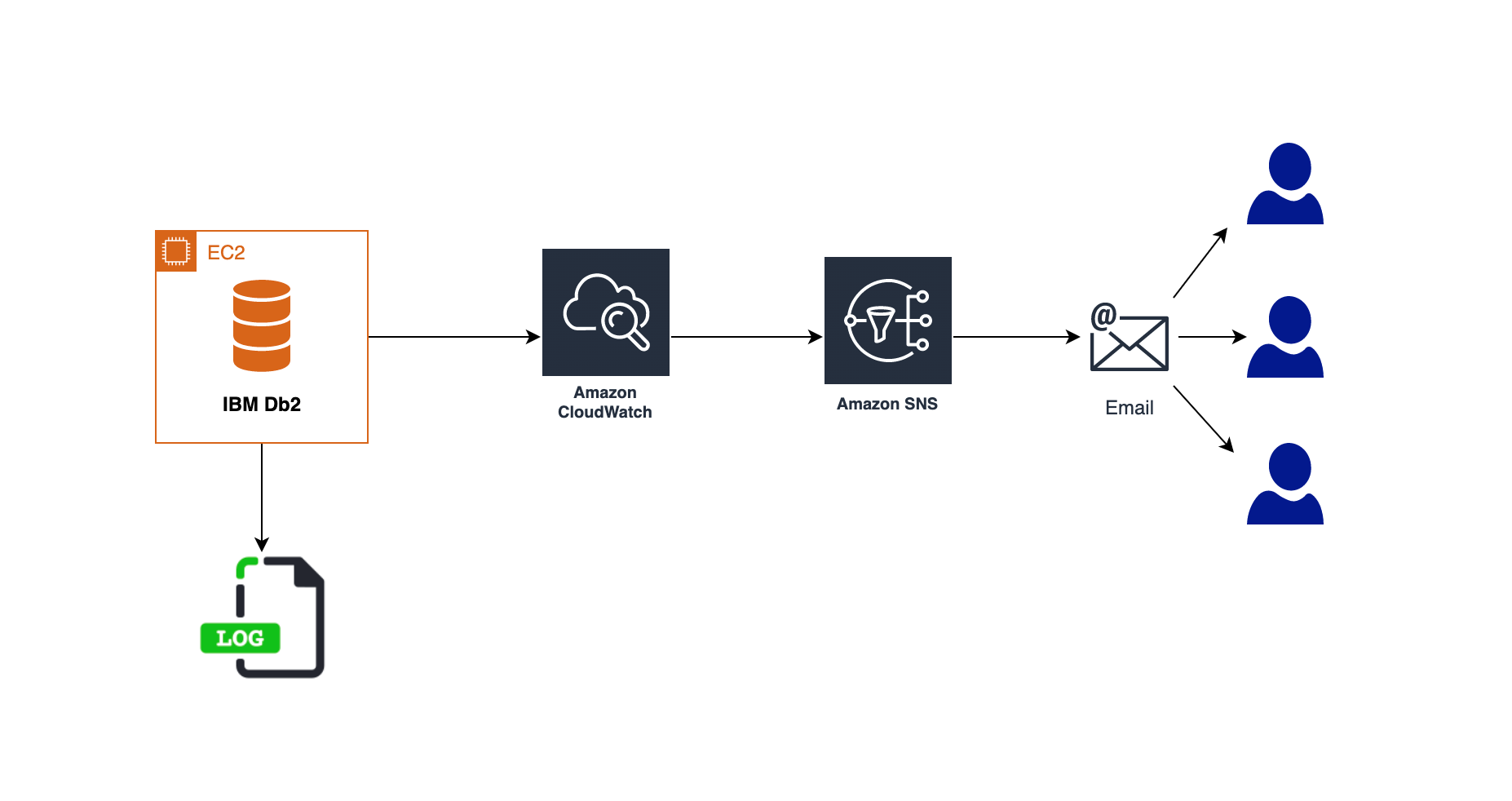
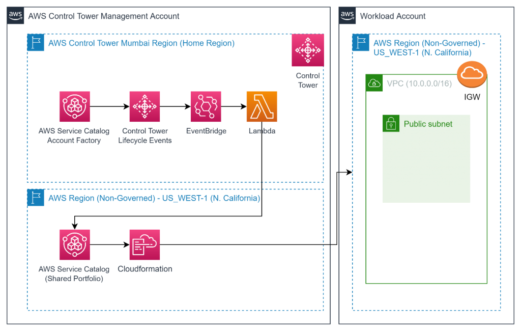
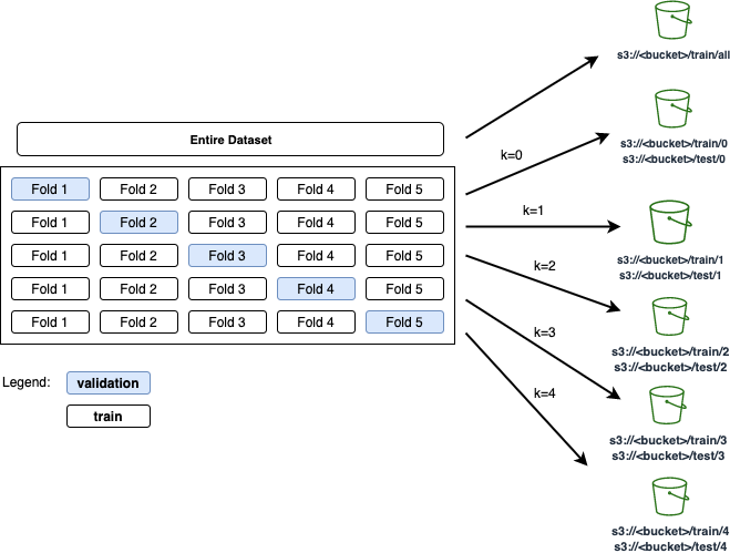
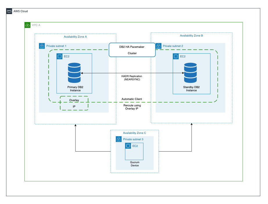
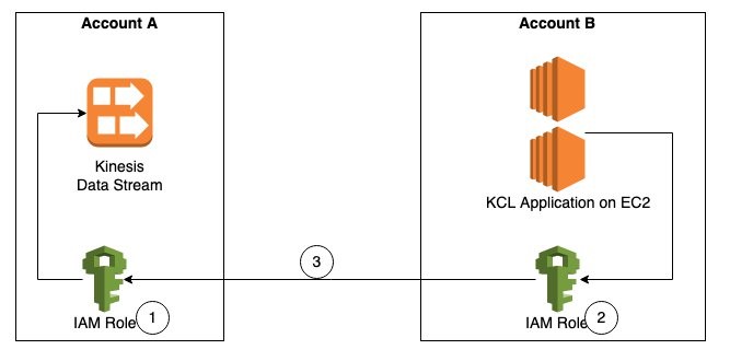
As shown in Figure 1, Account A has the Kinesis data stream and Account B has the KCL instances consuming from the Kinesis data stream in Account A. For the purposes of this blog post the KCL code is running on Amazon Elastic Compute Cloud (Amazon EC2).

Figure 1. Steps to access a cross-account Kinesis data stream

The steps to access a Kinesis data stream in one account from a KCL application in another account are:

Step 1 – Create AWS Identity and Access Management (IAM) role in Account A to access the Kinesis data stream with trust relationship with Account B.

Step 2 – Create IAM role in Account B to assume the role in Account A. This role is attached to the EC2 fleet running the KCL application.

Step 3 – Update the KCL application code to assume the role in Account A to read Kinesis data stream in Account A.

Prerequisites

  • KCL for Java version 2.3.4 or later.
  • AWS Security Token Service (AWS STS) SDK.
  • Create a Kinesis data stream named StockTradeStream in Account A and a producer to load data into the stream. If you do not have a producer, you can use the Amazon Kinesis Data Generator to send test data into your Kinesis data stream.

Walkthrough

Step 1 – Create IAM policies and IAM role in Account A

First, we will create an IAM role in Account A, with permissions to access the Kinesis data stream created in the same account. We will also add Account B as a trusted entity to this role.

  1. Create IAM policy kds-stock-trade-stream-policy to access Kinesis data stream in Account A using the following policy definition. This policy restricts access to specific Kinesis data stream.
{
    "Version": "2012-10-17",
    "Statement": [
        {
            "Sid": "Stmt123",
            "Effect": "Allow",
            "Action": [
                "kinesis:DescribeStream",
                "kinesis:GetShardIterator",
                "kinesis:GetRecords",
                "kinesis:ListShards",
                "kinesis:DescribeStreamSummary",
                "kinesis:RegisterStreamConsumer"
            ],
            "Resource": [
                "arn:aws:kinesis:us-east-1:Account-A-AccountNumber:stream/StockTradeStream"
            ]
        },
        {
            "Sid": "Stmt234",
            "Effect": "Allow",
            "Action": [
                "kinesis:SubscribeToShard",
                "kinesis:DescribeStreamConsumer"
            ],
            "Resource": [
                "arn:aws:kinesis:us-east-1:Account-A-AccountNumber:stream/StockTradeStream/*"
            ]
        }
    ]
}

Note: The above policy assumes the name of the Kinesis data stream is StockTradeStream.

  1. Create IAM role kds-stock-trade-stream-role in Account A.
aws iam create-role --role-name kds-stock-trade-stream-role --assume-role-policy-document "{\"Version\":\"2012-10-17\",\"Statement\":[{\"Effect\":\"Allow\",\"Principal\":{\"AWS\":[\"arn:aws:iam::Account-B-AccountNumber:root\"]},\"Action\":[\"sts:AssumeRole\"]}]}"
  1. Attach the kds-stock-trade-stream-policy IAM policy to kds-stock-trade-stream-role role.
aws iam attach-role-policy --policy-arn arn:aws:iam::Account-A-AccountNumber:policy/kds-stock-trade-stream-policy --role-name kds-stock-trade-stream-role

In the above steps, you will have to replace Account-A-AccountNumber with the AWS account number of the account that has the Kinesis data stream and Account-B-AccountNumber will need to be replaced with the AWS account number of the account that has the KCL application

Step 2 – Create IAM policies and IAM role in Account B

We will now create an IAM role in account B to assume the role created in Account A in Step 1. This role will also grant the KCL application access to Amazon DynamoDB and Amazon CloudWatch in Account B. For every KCL application, a DynamoDB table is used to keep track of the shards in a Kinesis data stream that are being leased and processed by the workers of the KCL consumer application. The name of the DynamoDB table is the same as the KCL application name. Similarly, the KCL application needs access to emit metrics to CloudWatch. Because the KCL application is running in Account B, we want to maintain the DynamoDB table and the CloudWatch metrics in the same account as the application code. For this blog post, our KCL application name is StockTradesProcessor.

  1. Create IAM policy kcl-stock-trader-app-policy, with permissions access to DynamoDB and CloudWatch in Account B, and to assume the kds-stock-trade-stream-role role created in Account A.
{
    "Version": "2012-10-17",
    "Statement": [
        {
            "Sid": "AssumeRoleInSourceAccount",
            "Effect": "Allow",
            "Action": "sts:AssumeRole",
            "Resource": "arn:aws:iam::Account-A-AccountNumber:role/kds-stock-trade-stream-role"
        },
        {
            "Sid": "Stmt456",
            "Effect": "Allow",
            "Action": [
                "dynamodb:CreateTable",
                "dynamodb:DescribeTable",
                "dynamodb:Scan",
                "dynamodb:PutItem",
                "dynamodb:GetItem",
                "dynamodb:UpdateItem",
                "dynamodb:DeleteItem"
            ],
            "Resource": [
                "arn:aws:dynamodb:us-east-1:Account-B-AccountNumber:table/StockTradesProcessor"
            ]
        },
        {
            "Sid": "Stmt789",
            "Effect": "Allow",
            "Action": [
                "cloudwatch:PutMetricData"
            ],
            "Resource": [
                "*"
            ]
        }
    ]
}

The above policy gives access to a DynamoDB table StockTradesProcessor. If you change you KCL application name, make sure you change the above policy to reflect the corresponding DynamoDB table name.

  1. Create role kcl-stock-trader-app-role in Account B to assume role in Account A.
aws iam create-role --role-name kcl-stock-trader-app-role --assume-role-policy-document "{\"Version\":\"2012-10-17\",\"Statement\":[{\"Effect\":\"Allow\",\"Principal\":{\"Service\":[\"ec2.amazonaws.com\"]},\"Action\":[\"sts:AssumeRole\"]}]}"
  1. Attach the policy kcl-stock-trader-app-policy to the kcl-stock-trader-app-role.
aws iam attach-role-policy --policy-arn arn:aws:iam::Account-B-AccountNumber:policy/kcl-stock-trader-app-policy --role-name kcl-stock-trader-app-role
  1. Create an instance profile with a name as kcl-stock-trader-app-role.
aws iam create-instance-profile --instance-profile-name kcl-stock-trader-app-role
  1. Attach the kcl-stock-trader-app-role role to the instance profile.
aws iam add-role-to-instance-profile --instance-profile-name kcl-stock-trader-app-role --role-name kcl-stock-trader-app-role
  1. Attach the kcl-stock-trader-app-role to the EC2 instances that are running the KCL code.
aws ec2 associate-iam-instance-profile --iam-instance-profile Name=kcl-stock-trader-app-role --instance-id <your EC2 instance>

In the above steps, you will have to replace Account-A-AccountNumber with the AWS account number of the account that has the Kinesis data stream, Account-B-AccountNumber will need to be replaced with the AWS account number of the account which has the KCL application and <your EC2 instance id> will need to be replaced with the correct EC2 instance id. This instance profile should be added to any new EC2 instances of the KCL application that are started.

Step 3 – Update KCL stock trader application to access cross-account Kinesis data stream

KCL application in java

To demonstrate the setup for cross-account access for KCL using Java, we have used the KCL stock trader application as the starting point and modified it to enable access to a Kinesis data stream in another AWS account.

After the IAM policies and roles have been created and attached to the EC2 instance running the KCL application, we will update the main class of the consumer application to enable cross-account access.

Setting up the integrated development environment (IDE)

To download and build the code for the stock trader application, follow these steps:

  1. Clone the source code from the GitHub repository to your computer.
$  git clone https://github.com/aws-samples/amazon-kinesis-learning
Cloning into 'amazon-kinesis-learning'...
remote: Enumerating objects: 169, done.
remote: Counting objects: 100% (77/77), done.
remote: Compressing objects: 100% (37/37), done.
remote: Total 169 (delta 16), reused 56 (delta 8), pack-reused 92
Receiving objects: 100% (169/169), 45.14 KiB | 220.00 KiB/s, done.
Resolving deltas: 100% (29/29), done.
  1. Create a project in your integrated development environment (IDE) with the source code you downloaded in the previous step. For this blog post, we are using Eclipse for our IDE, therefore the instructions will be specific to Eclipse project.
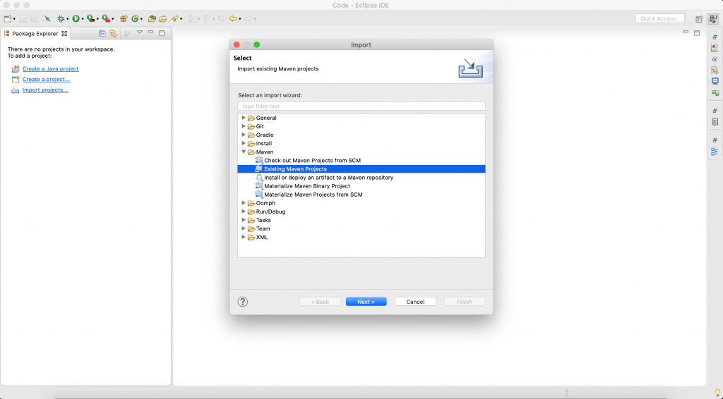
    1. Open Eclipse IDE. Select File -> Import.
      A dialog box will open, as shown in Figure 2.

Figure 2. Create an Eclipse project

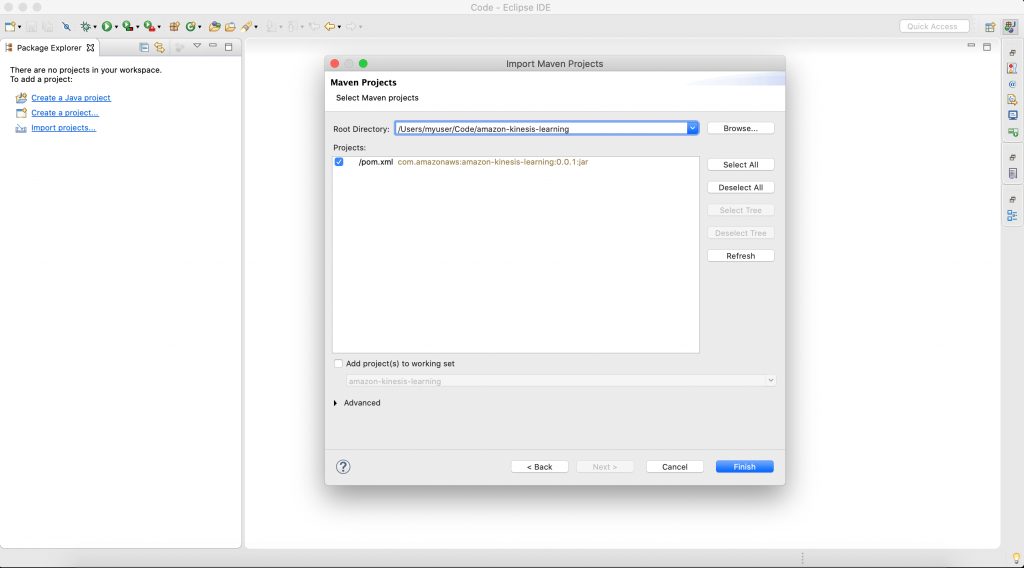
  1. Select Maven -> Existing Maven Projects, and select Next. Then you will be prompted to select a folder location for stock trader application.

Figure 3. Select the folder for your project

Select Browse, and navigate to the downloaded source code folder location. The IDE will automatically detect maven pom.xml.

Select Finish to complete the import. IDE will take 2–3 minutes to download all libraries to complete setup stock trader project.

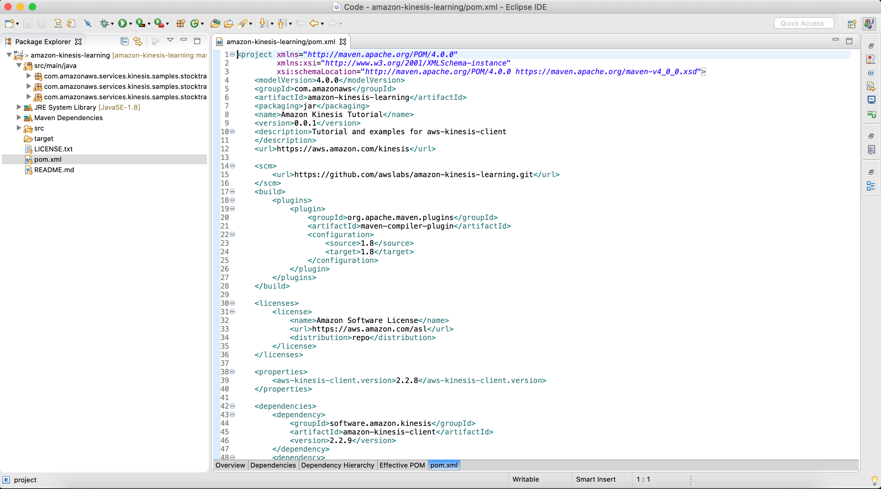
  1. After the setup is complete, the IDE will look like similar to Figure 4.
Figure 4. Final view of pom.xl file after setup is complete

Figure 4. Final view of pom.xl file after setup is complete

  1. Open pom.xml, and replace it with the following content. This will add all the prerequisites and dependencies required to build and package the jar application.
<project xmlns="http://maven.apache.org/POM/4.0.0"
         xmlns:xsi="http://www.w3.org/2001/XMLSchema-instance"
         xsi:schemaLocation="http://maven.apache.org/POM/4.0.0 https://maven.apache.org/maven-v4_0_0.xsd">
    <modelVersion>4.0.0</modelVersion>
    <groupId>com.amazonaws</groupId>
    <artifactId>amazon-kinesis-learning</artifactId>
    <packaging>jar</packaging>
    <name>Amazon Kinesis Tutorial</name>
    <version>0.0.1</version>
    <description>Tutorial and examples for aws-kinesis-client
    </description>
    <url>https://aws.amazon.com/kinesis</url>

    <scm>
        <url>https://github.com/awslabs/amazon-kinesis-learning.git</url>
    </scm>

    <licenses>
        <license>
            <name>Amazon Software License</name>
            <url>https://aws.amazon.com/asl</url>
            <distribution>repo</distribution>
        </license>
    </licenses>

    <properties>
        <aws-kinesis-client.version>2.3.4</aws-kinesis-client.version>
    </properties>

    <dependencies>
        <dependency>
            <groupId>software.amazon.kinesis</groupId>
            <artifactId>amazon-kinesis-client</artifactId>
            <version>2.3.4</version>
        </dependency>
        <dependency>
            <groupId>commons-logging</groupId>
            <artifactId>commons-logging</artifactId>
            <version>1.2</version>
        </dependency>
		<dependency>
		    <groupId>software.amazon.awssdk</groupId>
		    <artifactId>sts</artifactId>
		    <version>2.16.74</version>
		</dependency>
		<dependency>
       <groupId>org.slf4j</groupId>
       <artifactId>slf4j-simple</artifactId>
       <version>1.7.25</version>
   </dependency>
    </dependencies>

 	<build>
        <finalName>amazon-kinesis-learning</finalName>
        <plugins>

            <plugin>
                <groupId>org.apache.maven.plugins</groupId>
                <artifactId>maven-compiler-plugin</artifactId>
                <version>3.6.1</version>
                <configuration>
                    <source>1.8</source>
                    <target>1.8</target>
                </configuration>
            </plugin>

            <plugin>
                <groupId>org.apache.maven.plugins</groupId>
                <artifactId>maven-assembly-plugin</artifactId>
                <version>3.1.1</version>

                <configuration>
                    <descriptorRefs>
                        <descriptorRef>jar-with-dependencies</descriptorRef>
                    </descriptorRefs>
                </configuration>

                <executions>
                    <execution>
                        <id>make-assembly</id>
                        <phase>package</phase>
                        <goals>
                            <goal>single</goal>
                        </goals>
                    </execution>
                </executions>
    
            </plugin>
        </plugins>
    </build>


</project>

Update the main class of consumer application

The updated code for the StockTradesProcessor.java class is shown as follows. The changes made to the class to enable cross-account access are highlighted in bold.

package com.amazonaws.services.kinesis.samples.stocktrades.processor;

import java.util.UUID;
import java.util.logging.Level;
import java.util.logging.Logger;

import org.apache.commons.logging.Log;
import org.apache.commons.logging.LogFactory;

import software.amazon.awssdk.auth.credentials.AwsCredentialsProvider;
import software.amazon.awssdk.regions.Region;
import software.amazon.awssdk.services.dynamodb.DynamoDbAsyncClient;
import software.amazon.awssdk.services.cloudwatch.CloudWatchAsyncClient;
import software.amazon.awssdk.services.kinesis.KinesisAsyncClient;
import software.amazon.awssdk.services.sts.StsClient; import software.amazon.awssdk.services.sts.auth.StsAssumeRoleCredentialsProvider; import software.amazon.awssdk.services.sts.model.AssumeRoleRequest;
import software.amazon.kinesis.common.ConfigsBuilder;
import software.amazon.kinesis.common.KinesisClientUtil;
import software.amazon.kinesis.coordinator.Scheduler;

/**
 * Uses the Kinesis Client Library (KCL) 2.2.9 to continuously consume and process stock trade
 * records from the stock trades stream. KCL monitors the number of shards and creates
 * record processor instances to read and process records from each shard. KCL also
 * load balances shards across all the instances of this processor.
 *
 */
public class StockTradesProcessor {

    private static final Log LOG = LogFactory.getLog(StockTradesProcessor.class);

    private static final Logger ROOT_LOGGER = Logger.getLogger("");
    private static final Logger PROCESSOR_LOGGER =
            Logger.getLogger("com.amazonaws.services.kinesis.samples.stocktrades.processor.StockTradeRecordProcessor");

    private static void checkUsage(String[] args) {
        if (args.length != 5) {
            System.err.println("Usage: " + StockTradesProcessor.class.getSimpleName()
                    + " <application name> <stream name> <region> <role arn> <role session name>");
            System.exit(1);
        }
    }

    /**
     * Sets the global log level to WARNING and the log level for this package to INFO,
     * so that we only see INFO messages for this processor. This is just for the purpose
     * of this tutorial, and should not be considered as best practice.
     *
     */
    private static void setLogLevels() {
        ROOT_LOGGER.setLevel(Level.WARNING);
        // Set this to INFO for logging at INFO level. Suppressed for this example as it can be noisy.
        PROCESSOR_LOGGER.setLevel(Level.WARNING);
    }
    
    private static AwsCredentialsProvider roleCredentialsProvider(String roleArn, String roleSessionName, Region region) { AssumeRoleRequest assumeRoleRequest = AssumeRoleRequest.builder() .roleArn(roleArn) .roleSessionName(roleSessionName) .durationSeconds(900) .build(); LOG.warn("Initializing assume role request session: " + assumeRoleRequest.roleSessionName()); StsClient stsClient = StsClient.builder().region(region).build(); StsAssumeRoleCredentialsProvider stsAssumeRoleCredentialsProvider = StsAssumeRoleCredentialsProvider .builder() .stsClient(stsClient) .refreshRequest(assumeRoleRequest) .asyncCredentialUpdateEnabled(true) .build(); LOG.warn("Initializing sts role credential provider: " + stsAssumeRoleCredentialsProvider.prefetchTime().toString()); return stsAssumeRoleCredentialsProvider; }

    public static void main(String[] args) throws Exception {
        checkUsage(args);

        setLogLevels();

        String applicationName = args[0];
        String streamName = args[1];
        Region region = Region.of(args[2]);
        String roleArn = args[3]; String roleSessionName = args[4]; 
        
        if (region == null) {
            System.err.println(args[2] + " is not a valid AWS region.");
            System.exit(1);
        }
        
        AwsCredentialsProvider awsCredentialsProvider = roleCredentialsProvider(roleArn,roleSessionName, region); KinesisAsyncClient kinesisClient = KinesisClientUtil.createKinesisAsyncClient(KinesisAsyncClient.builder().region(region).credentialsProvider(awsCredentialsProvider));
        DynamoDbAsyncClient dynamoClient = DynamoDbAsyncClient.builder().region(region).build();
        CloudWatchAsyncClient cloudWatchClient = CloudWatchAsyncClient.builder().region(region).build();
        StockTradeRecordProcessorFactory shardRecordProcessor = new StockTradeRecordProcessorFactory();
        ConfigsBuilder configsBuilder = new ConfigsBuilder(streamName, applicationName, kinesisClient, dynamoClient, cloudWatchClient, UUID.randomUUID().toString(), shardRecordProcessor);

        Scheduler scheduler = new Scheduler(
                configsBuilder.checkpointConfig(),
                configsBuilder.coordinatorConfig(),
                configsBuilder.leaseManagementConfig(),
                configsBuilder.lifecycleConfig(),
                configsBuilder.metricsConfig(),
                configsBuilder.processorConfig(),
                configsBuilder.retrievalConfig()
        );
        int exitCode = 0;
        try {
            scheduler.run();
        } catch (Throwable t) {
            LOG.error("Caught throwable while processing data.", t);
            exitCode = 1;
        }
        System.exit(exitCode);

    }

}

Let’s review the changes made to the code to understand the key parts of how the cross-account access works.

AssumeRoleRequest assumeRoleRequest = AssumeRoleRequest.builder() .roleArn(roleArn) .roleSessionName(roleSessionName) .durationSeconds(900) .build();

AssumeRoleRequest class is used to get the credentials to access the Kinesis data stream in Account A using the role that was created. The value of the variable assumeRoleRequest is passed to the StsAssumeRoleCredentialsProvider.

StsClient stsClient = StsClient.builder().region(region).build();
StsAssumeRoleCredentialsProvider stsAssumeRoleCredentialsProvider = StsAssumeRoleCredentialsProvider .builder() .stsClient(stsClient) .refreshRequest(assumeRoleRequest) .asyncCredentialUpdateEnabled(true) .build();

StsAssumeRoleCredentialsProvider periodically sends an AssumeRoleRequest to the AWS STS to maintain short-lived sessions to use for authentication. Using refreshRequest, these sessions are updated asynchronously in the background as they get close to expiring. As asynchronous refresh is not set by default, we explicitly set it to true using asyncCredentialUpdateEnabled.

AwsCredentialsProvider awsCredentialsProvider = roleCredentialsProvider(roleArn,roleSessionName, region);
KinesisAsyncClient kinesisClient = KinesisClientUtil.createKinesisAsyncClient(KinesisAsyncClient.builder().region(region).credentialsProvider(awsCredentialsProvider));

  • KinesisAsyncClient is the client for accessing Kinesis asynchronously. We can create an instance of KinesisAsyncClient by passing to it the credentials to access the Kinesis data stream in Account A through the assume role. The values of Kinesis, DynamoDB, and the CloudWatch client along with the stream name, application name is used to create a ConfigsBuilder instance.
  • The ConfigsBuilder instance is used to create the KCL scheduler (also known as KCL worker in KCL versions 1.x).
  • The scheduler creates a new thread for each shard (assigned to this consumer instance), which continuously loops to read records from the data stream. It then invokes the record processor instance (StockTradeRecordProcessor in this example) to process each batch of records received. This is the class which will contain your record processing logic. The Developing Custom Consumers with Shared Throughput Using KCL section of the documentation will provide more details on the working of KCL.

KCL application in python

In this section we will show you how to configure a KCL application written in Python to access a cross-account Kinesis data stream.

A.      Steps 1 and 2 from earlier remain the same and will need to be completed before moving ahead. After the IAM roles and policies have been created, log into the EC2 instance and clone the amazon-kinesis-client-python repository using the following command.

git clone https://github.com/awslabs/amazon-kinesis-client-python.git

B.      Navigate to the amazon-kinesis-client-python directory and run the following commands.

sudo yum install python-pip
sudo pip install virtualenv
virtualenv /tmp/kclpy-sample-env
source /tmp/kclpy-sample/env/bin/activate
pip install amazon_kclpy

C.      Next, navigate to amazon-kinesis-client-python/samples and open the sample.properties file. The properties file has properties such as streamName, application name, and credential information that lets you customize the configuration for your use case.

D.      We will modify the properties file to change the stream name and application name, and to add the credentials to enable access to a Kinesis data stream in a different account. You can replace the sample.properties file and replace with the following snippet. The bolded sections show the changes we have made.

# The script that abides by the multi-language protocol. This script will

# be executed by the MultiLangDaemon, which will communicate with this script

# over STDIN and STDOUT according to the multi-language protocol.

executableName = sample_kclpy_app.py

# The name of an Amazon Kinesis stream to process.

streamName = StockTradeStream

# Used by the KCL as the name of this application. Will be used as the name

# of an Amazon DynamoDB table which will store the lease and checkpoint

# information for workers with this application name

applicationName = StockTradesProcessor

# Users can change the credentials provider the KCL will use to retrieve credentials.

# The DefaultAWSCredentialsProviderChain checks several other providers, which is

# described here:

# http://docs.aws.amazon.com/AWSJavaSDK/latest/javadoc/com/amazonaws/auth/DefaultAWSCredentialsProviderChain.html

#AWSCredentialsProvider = DefaultAWSCredentialsProviderChain

AWSCredentialsProvider = STSAssumeRoleSessionCredentialsProvider|arn:aws:iam::Account-A-AccountNumber:role/kds-stock-trade-stream-role|kinesiscrossaccount

AWSCredentialsProviderDynamoDB = DefaultAWSCredentialsProviderChain

AWSCredentialsProviderCloudWatch = DefaultAWSCredentialsProviderChain

# Appended to the user agent of the KCL. Does not impact the functionality of the

# KCL in any other way.

processingLanguage = python/2.7

# Valid options at TRIM_HORIZON or LATEST.

# See http://docs.aws.amazon.com/kinesis/latest/APIReference/API_GetShardIterator.html#API_GetShardIterator_RequestSyntax

initialPositionInStream = LATEST

# The following properties are also available for configuring the KCL Worker that is created

# by the MultiLangDaemon.

# The KCL defaults to us-east-1

#regionName = us-east-1

In the above step, you will have to replace Account-A-AccountNumber with the AWS account number of the account that has the kinesis stream.

We use the STSAssumeRoleSessionCredentialsProvider class and pass to it the role created in Account A which have permissions to access the Kinesis data stream. This gives the KCL application in Account B permissions to read the Kinesis data stream in Account A. The DynamoDB lease table and the CloudWatch metrics are in Account B. Hence, we can use the DefaultAWSCredentialsProviderChain for AWSCredentialsProviderDynamoDB and AWSCredentialsProviderCloudWatch in the properties file. You can now save the sample.properties file.

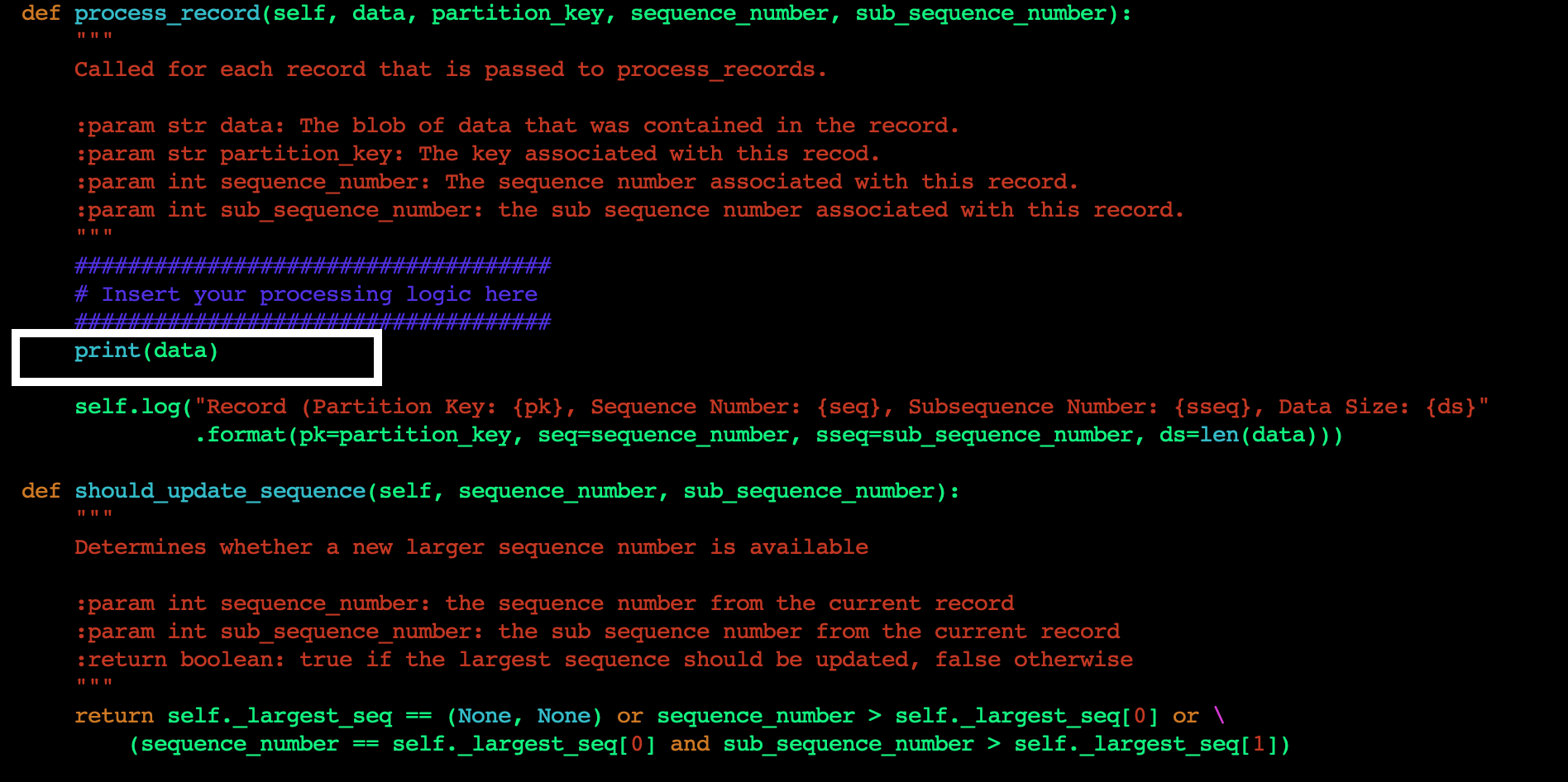
E.      Next, we will change the application code to print the data read from the Kinesis data stream to standard output (STDOUT). Edit the sample_kclpy_app.py under the samples directory. You will add all your application code logic in the process_record method. This method is called for every record in the Kinesis data stream. For this blog post, we will add a single line to the method to print the records to STDOUT, as shown in Figure 5.

Figure 5. Add custom code to process_record method

Figure 5. Add custom code to process_record method

F.       Save the file, and run the following command to build the project with the changes you just made.

cd amazon-kinesis-client-python/
python setup.py install

G.     Now you are ready to run the application. To start the KCL application, run the following command from the amazon-kinesis-client-python directory.

`amazon_kclpy_helper.py --print_command --java /usr/bin/java --properties samples/sample.properties`

This will start the application. Your application is now ready to read the data from the Kinesis data stream in another account and display the contents of the stream on STDOUT. When the producer starts writing data to the Kinesis data stream in Account A, you will start seeing those results being printed.

Clean Up

Once you are done testing the cross-account access make sure you clean up your environment to avoid incurring cost. As part of the cleanup we recommend you delete the Kinesis data stream, StockTradeStream, the EC2 instances that the KCL application is running on, and the DynamoDB table that was created by the KCL application.

Conclusion

In this blog post, we discussed the techniques to configure your KCL applications written in Java and Python to access a Kinesis data stream in a different AWS account. We also provided sample code and configurations which you can modify and use in your application code to set up the cross-account access. Now you can continue to build a multi-account strategy on AWS, while being able to easily access your Kinesis data streams from applications in multiple AWS accounts.

Field Notes: Automate Disaster Recovery for AWS Workloads with Druva

Post Syndicated from Girish Chanchlani original https://aws.amazon.com/blogs/architecture/field-notes-automate-disaster-recovery-for-aws-workloads-with-druva/

This post was co-written by Akshay Panchmukh, Product Manager, Druva and Girish Chanchlani, Sr Partner Solutions Architect, AWS.

The Uptime Institute’s Annual Outage Analysis 2021 report estimated that 40% of outages or service interruptions in businesses cost between $100,000 and $1 million, while about 17% cost more than $1 million. To guard against this, it is critical for you to have a sound data protection and disaster recovery (DR) strategy to minimize the impact on your business. With the greater adoption of the public cloud, most companies are either following a hybrid model with critical workloads spread across on-premises data centers and the cloud or are all in the cloud.

In this blog post, we focus on how Druva, a SaaS based data protection solution provider, can help you implement a DR strategy for your workloads running in Amazon Web Services (AWS). We explain how to set up protection of AWS workloads running in one AWS account, and fail them over to another AWS account or Region, thereby minimizing the impact of disruption to your business.

Overview of the architecture

In the following architecture, we describe how you can protect your AWS workloads from outages and disasters. You can quickly set up a DR plan using Druva’s simple and intuitive user interface, and within minutes you are ready to protect your AWS infrastructure.

Figure 1. Druva architecture

Druva’s cloud DR is built on AWS using native services to provide a secure operating environment for comprehensive backup and DR operations. With Druva, you can:

  • Seamlessly create cross-account DR sites based on source sites by cloning Amazon Virtual Private Clouds (Amazon VPCs) and their dependents.
  • Set up backup policies to automatically create and copy snapshots of Amazon Elastic Compute Cloud (Amazon EC2) and Amazon Relational Database Service (Amazon RDS) instances to DR Regions based on recovery point objective (RPO) requirements.
  • Set up service level objective (SLO) based DR plans with options to schedule automated tests of DR plans and ensure compliance.
  • Monitor implementation of DR plans easily from the Druva console.
  • Generate compliance reports for DR failover and test initiation.

Other notable features include support for automated runbook initiation, selection of target AWS instance types for DR, and simplified orchestration and testing to help protect and recover data at scale. Druva provides the flexibility to adopt evolving infrastructure across geographic locations, adhere to regulatory requirements (such as, GDPR and CCPA), and recover workloads quickly following disasters, helping meet your business-critical recovery time objectives (RTOs). This unified solution offers taking snapshots as frequently as every five minutes, improving RPOs. Because it is a software as a service (SaaS) solution, Druva helps lower costs by eliminating traditional administration and maintenance of storage hardware and software, upgrades, patches, and integrations.

We will show you how to set up Druva to protect your AWS workloads and automate DR.

Step 1: Log into the Druva platform and provide access to AWS accounts

After you sign into the Druva Cloud Platform, you will need to grant Druva third-party access to your AWS account by pressing Add New Account button, and following the steps as shown in Figure 2.

Figure 2. Add AWS account information

Druva uses AWS Identity and Access Management (IAM) roles to access and manage your AWS workloads. To help you with this, Druva provides an AWS CloudFormation template to create a stack or stack set that generates the following:

  • IAM role
  • IAM instance profile
  • IAM policy

The generated Amazon Resource Name (ARN) of the IAM role is then linked to Druva so that it can run backup and DR jobs for your AWS workloads. Note that Druva follows all security protocols and best practices recommended by AWS. All access permissions to your AWS resources and Regions are controlled by IAM.

After you have logged into Druva and set up your account, you can now set up DR for your AWS workloads. The following steps will allow you to set up DR for AWS infrastructure.

Step 2: Identify the source environment

A source environment refers to a logical grouping of Amazon VPCs, subnets, security groups, and other infrastructure components required to run your application.

Figure 3. Create a source environment

In this step, create your source environment by selecting the appropriate AWS resources you’d like to set up for failover. Druva currently supports Amazon EC2 and Amazon RDS as sources that can be protected. With Druva’s automated DR, you can failover these resources to a secondary site with the press of a button.

Figure 4. Add resources to a source environment

Note that creating a source environment does not create or update existing resources or configurations in your AWS account. It only saves this configuration information with Druva’s service.

Step 3: Clone the environment

The next step is to clone the source environment to a Region where you want to failover in case of a disaster. Druva supports cloning the source environment to another Region or AWS account that you have selected. Cloning essentially replicates the source infrastructure in the target Region or account, which allows the resources to be failed over quickly and seamlessly.

Figure 5. Clone the source environment

Step 4: Set up a backup policy

You can create a new backup policy or use an existing backup policy to create backups in the cloned or target Region. This enables Druva to restore instances using the backup copies.

Figure 6. Create a new backup policy or use an existing backup policy

Figure 7. Customize the frequency of backup schedules

Step 5: Create the DR plan

A DR plan is a structured set of instructions designed to recover resources in the event of a failure or disaster. DR aims to get you back to the production-ready setup with minimal downtime. Follow these steps to create your DR plan.

  1. Create DR Plan: Press Create Disaster Recovery Plan button to open the DR plan creation page.

Figure 8. Create a disaster recovery plan

  1. Name: Enter the name of the DR plan.
    Service Level Objective (SLO): Enter your RPO and RTO.
    • Recovery Point Objective – Example: If you set your RPO as 24 hours, and your backup was scheduled daily at 8:00 PM, but a disaster occurred at 7:59 PM, you would be able to recover data that was backed up on the previous day at 8:00 PM. You would lose the data generated after the last backup (24 hours of data loss).
    • Recovery Time Objective – Example: If you set your RTO as 30 hours, when a disaster occurred, you would be able to recover all critical IT services within 30 hours from the point in time the disaster occurs.

Figure 9. Add your RTO and RPO requirements

  1. Create your plan based off the source environment, target environment, and resources.
Environments
Source Account By default, this is the Druva account in which you are currently creating the DR plan.
Source Environment Select the source environment applicable within the Source Account (your Druva account in which you’re creating the DR plan).
Target Account Select the same or a different target account.
Target Environment Select the Target Environment, applicable within the Target Account.
Resources
Create Policy If you do not have a backup policy, then you can create one.
Add Resources Add resources from the source environment that you want to restore. Make sure the verification column shows a ‘Valid Backup Policy’ status. This ensures that the backup policy is frequently creating copies as per the RPO defined previously.

Figure 10. Create DR plan based off the source environment, target environment, and resources

  1. Identify target instance type, test plan instance type, and run books for this DR plan.
Target Instance Type Target Instance Type can be selected. If instance type is not selected then:

  • Select an instance type which is large in size.
  • Select an instance type which is smaller.
  • Fail the creation of the instance.
Test Plan Instance Type There are many options. To reduce incurring cost, the lower instance type can be selected from all available AWS instance types.
Run Books Select this option if you would like to shutdown the source server after failover occurs.

Figure 11. Identify target instance type, test plan instance type, and run books

Step 6: Test the DR plan

After you have defined your DR plan, it is time to test it so that you can—when necessary—initiate a failover of resources to the target Region. You can now easily try this on the resources in the cloned environment without affecting your production environment.

Figure 12. Test the DR plan

Testing your DR plan will help you to find answers for some of the questions like: How long did the recovery take? Did I meet my RTO and RPO objectives?

Step 7: Initiate the DR plan

After you have successfully tested the DR plan, it can easily be initiated with the click of a button to failover your resources from the source Region or account to the target Region or account.

Conclusion

With the growth of cloud-based services, businesses need to ensure that mission-critical applications that power their businesses are always available. Any loss of service has a direct impact on the bottom line, which makes business continuity planning a critical element to any organization. Druva offers a simple DR solution which will help you keep your business always available.

Druva provides unified backup and cloud DR with no need to manage hardware, software, or costs and complexity. It helps automate DR processes to ensure your teams are prepared for any potential disasters while meeting compliance and auditing requirements.

With Druva, you can easily validate your RTO and RPO with automated regular DR testing, cross-account DR for protection against attacks and accidental deletions, and ensure backups are isolated from your primary production account for DR planning. With cross-Region DR, you can duplicate the entire Amazon VPC environment across Regions to protect you against Regionwide failures. In conclusion, Druva is a complete solution built with a goal to protect your native AWS workloads from any disasters.

To learn more, visit: https://www.druva.com/use-cases/aws-cloud-backup/

Field Notes provides hands-on technical guidance from AWS Solutions Architects, consultants, and technical account managers, based on their experiences in the field solving real-world business problems for customers.
Akshay Panchmukh

Akshay Panchmukh

Akshay Panchmukh is the Product Manager focusing on cloud-native workloads at Druva. He loves solving complex problems for customers and helping them achieve their business goals. He leverages his SaaS product and design thinking experience to help enterprises build a complete data protection solution. He works combining the best of technology, data, product, empathy, and design to execute a successful product vision.