Post Syndicated from Ben Everard original https://www.raspberrypi.org/blog/neopixel-dithering-with-pico/
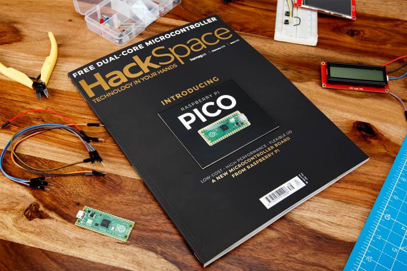
In the extra special Raspberry Pi Pico launch issue of HackSpace magazine, editor Ben Everard shows you how to get extra levels of brightness out of your LEDs with our new board.
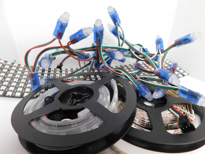
WS2812B LEDs, commonly known as NeoPixels, are cheap and widely available LEDs. They have red, green, and blue LEDs in a single package with a microcontroller that lets you control a whole string of them using just one pin on your microcontroller.
However, they do have a couple of disadvantages:
1) The protocol needed to control them is timing-dependent and often has to be bit-banged.
2) Each colour has 8 bits, so has 255 levels of brightness. However, these aren’t gamma-corrected, so the low levels of brightness have large steps between them. For small projects, we often find ourselves only using the lower levels of brightness, so often only have 10 or 20 usable levels of brightness.
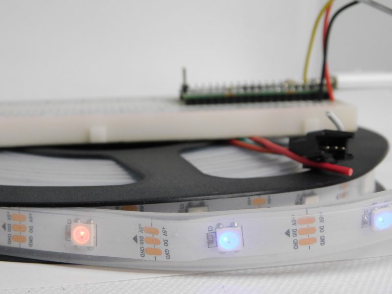
We’re going to look at how two features of Pico help solve these problems. Firstly, Programmable I/O (PIO) lets us implement the control protocol on a state machine rather than the main processing cores. This means that we don’t have to dedicate any processor time to sending the data out. Secondly, having two cores means we can use one of the processing cores to dither the NeoPixels. This means shift them rapidly between different brightness levels to make pseudo-levels of brightness.
For example, if we wanted a brightness level halfway between levels 3 and 4, we’d flick the brightness back and forth between 3 and 4. If we can do this fast enough, our eyes blur this into a single brightness level and we don’t see the flicker. By varying the amount of time at levels 3 and 4, we can make many virtual levels of brightness. While one core is doing this, we still have a processing core completely free to manipulate the data we want to display.
First, we’ll need a PIO program to communicate with the WS2812B LEDs. The Pico development team have provided an example PIO program to work with – you can see the full details here, but we’ll cover the essentials here. The PIO code is:
.program ws2812
.side_set 1
.define public T1 2
.define public T2 5
.define public T3 3
bitloop:
 out x, 1 side 0 [T3 - 1]
 jmp !x do_zero side 1 [T1 - 1]
 do_one:
 jmp bitloop side 1 [T2 - 1]
 do_zero:
 nop side 0 [T2 - 1]
We looked at the PIO syntax in the main cover feature, but it’s basically an assembly language for the PIO state machine. The WS2812B protocol uses pulses at a rate of 800kHz, but the length of the pulse determines if a 1 or a 0 is being sent. This code uses jumps to move through the loop to set the timings depending on whether the bit (stored in the register x) is 0 or 1. The T1, T2, and T3 variables hold the timings, so are used to calculate the delays (with 1 taken off as the instruction itself takes one clock cycle). There’s also a section in the pio file that links the PIO code and the C code:
% c-sdk {
#include "hardware/clocks.h"
static inline void ws2812_program_init(PIO pio,
uint sm, uint offset, uint pin, float freq, bool
rgbw) {
 pio_gpio_select(pio, pin);
 pio_sm_set_consecutive_pindirs(pio, sm, pin, 1,
true);
 pio_sm_config c = ws2812_program_get_default_
config(offset);
 sm_config_set_sideset_pins(&c, pin);
 sm_config_set_out_shift(&c, false, true, rgbw ?
32 : 24);
 sm_config_set_fifo_join(&c, PIO_FIFO_JOIN_TX);
 int cycles_per_bit = ws2812_T1 + ws2812_T2 +
ws2812_T3;
 float div = clock_get_hz(clk_sys) / (freq *
cycles_per_bit);
 sm_config_set_clkdiv(&c, div);
 pio_sm_init(pio, sm, offset, &c);
 pio_sm_set_enable(pio, sm, true);
}
%}
Most of this is setting the various PIO options – the full range is detailed in the Raspberry Pi Pico C/C++ SDK document.
 sm_config_set_out_shift(&c, false, true, rgbw ? 32
: 24);
This line sets up the output shift register which holds each 32 bits of data before it’s moved bit by bit into the PIO state machine. The parameters are the config (that we’re setting up and will use to initialise the state machine); a Boolean value for shifting right or left (false being left); and a Boolean value for autopull which we have set to true. This means that whenever the output shift register falls below a certain threshold (set in the next parameter), the PIO will automatically pull in the next 32 bits of data.
The final parameter is set using the expression rgbw ? 32 : 24. This means that if the variable rgbw is true, the value 32 is passed, otherwise 24 is passed. The rbgw variable is passed into this function when we create the PIO program from our C program and is used to specify whether we’re using an LED strip with four LEDs in each (using one red, one green, one blue, and one white) or three (red, green, and blue).
The PIO hardware works on 32-bit words, so each chunk of data we write with the values we want to send to the LEDs has to be 32 bits long. However, if we’re using RGB LED strips, we actually want to work in 24-bit lengths. By setting autopull to 24, we still pull in 32 bits each time, but once 24 bits have been read, another 32 bits are pulled in which overwrite the remaining 8 bits.
sm_config_set_fifo_join(&c, PIO_FIFO_JOIN_TX);Each state machine has two four-word FIFOs attached to it. These can be used for one going in and one coming out. However, as we only have data going into our state machine, we can join them together to form a single eight-word FIFO using the above line. This gives us a small buffer of time to write data to in order to avoid the state machine running out of data and execution stalling. The following three lines are used to set the speed the state machine runs at:
int cycles_per_bit = ws2812_T1 + ws2812_T2 +
ws2812_T3;
 float div = clock_get_hz(clk_sys) / (freq *
cycles_per_bit);
 sm_config_clkdiv(&c, div);
The WS2812B protocol demands that data is sent out at a rate of 800kHz. However, each bit of data requires a number of state machine cycles. In this case, they’re defined in the variables T1, T2, and T3. If you look back at the original PIO program, you’ll see that these are used in the delays (always with 1 taken off the value because the initial instruction takes one cycle before the delay kicks in). Every loop of the PIO program will take T1 + T2 + T3 cycles. We use these values to calculate the speed we want the state machine to run at, and from there we can work out the divider we need to slow the system clock down to the right speed for the state machine. The final two lines just initialise and enable the state machine.
The main processor
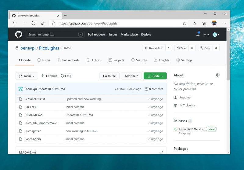
That’s the code that’s running on the state machine, so let’s now look at the code that’s running on our main processor cores. The full code is on github. Let’s first look at the code running on the second core (we’ll look at how to start this code running shortly), as this controls the light levels of the LEDs.
static inline void put_pixel(uint32_t pixel_grb) {
pio_sm_put_blocking(pio0, 0, pixel_grb << 8u);
}
static inline uint32_t urgb_u32(uint8_t r, uint8_t
g, uint8_t b) {
return
((uint32_t) (r) << 8) |
((uint32_t) (g) << 16) |
(uint32_t) (b);
}
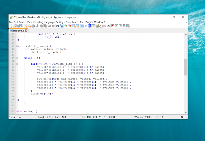
void ws2812b_core() {
int valuer, valueg, valueb;
int shift = bit_depth-8;
while (1){
for(int i=0; i<STRING_LEN; i++) {
valueb=(pixelsb[i] + errorsb[i]) >> shift;
valuer=(pixelsr[i] + errorsr[i]) >> shift;
valueg=(pixelsg[i] + errorsg[i]) >> shift;
put_pixel(urgb_u32(valuer, valueg, valueb));
errorsb[i] = (pixelsb[i] + errorsb[i]) -
(valueb << shift);
errorsr[i] = (pixelsr[i] + errorsr[i]) -
(valuer << shift);
errorsg[i] = (pixelsg[i] + errorsg[i]) -
(valueg << shift);
}
sleep_us(400);
}
}We start by defining a virtual bit depth. This is how many bits per pixel you can use. Our code will then attempt to create the necessary additional brightness levels. It will run as fast as it can drive the LED strip, but if you try to do too many brightness levels, you’ll start to notice flickering.
We found twelve to be about the best with strings up to around 100 LEDs, but you can experiment with others. Our code works with two arrays – pixels which holds the values that we want to display, and errors which holds the error in what we’ve displayed so far (there are three of each for the different colour channels).
To explain that latter point, let’s take a look at the algorithm for determining how to light the LED. We borrowed this from the source code of Fadecandy by Micah Scott, but it’s a well-used algorithm for calculating error rates. We have an outer while loop that just keeps pushing out data to the LEDs as fast as possible. We don’t care about precise timings and just want as much speed as possible. We then go through each pixel.
The corresponding item in the errors array holds the cumulative amount our LED has been underlit so far compared to what we want it to be. Initially, this will be zero, but with each loop (if there’s a difference between what we want to light the LED and what we can light the LED) this error value will increase. These two numbers (the closest light level and the error) added together give the brightness at the pseudo-level, so we need to bit-shift this by the difference between our virtual level and the 8-bit brightness levels that are available.
This gives us the value for this pixel which we write out. We then need to calculate the new error level. Let’s take a look at what this means in practice. Suppose we want a brightness level halfway between 1 and 2 in the 8-bit levels. To simplify things, we’ll use nine virtual bits. 1 and 2 in 8-bit is 2 and 4 in 9 bits (adding an extra 0 to the end multiplies everything by a power of 2), so halfway between these two is a 9-bit value of 3 (or 11 in binary, which we’ll use from now on).
In the first iteration of our loop, pixels is 11, errors is 0, and shift is 1.
value = 11 >> 1 = 1
errors = 11 – 10 = 1
So this time, the brightness level of 1 is written out. The second iteration, we have:
value = 100 >> 1 = 10
errors = 100 – 100 = 0
So this time, the brightness level of 10 (in binary, or 2 in base 10) is written out. This time, the errors go back to 0, so we’re in the same position as at the start of the first loop. In this case, the LED will flick between the two brightness levels each loop so you’ll have a brightness half way between the two.
Using this simple algorithm, we can experiment with different virtual bit-depths. The algorithm will always handle the calculations for us, but we just have to see what creates the most pleasing visual effect for the eye. The larger the virtual bit depth, the more potential iterations you have to go through before the error accumulates enough to create a correction, so the more likely you are to see flicker. The biggest blocker to increasing the virtual bit depth is the sleep_us(400). This is needed to reset the LED strip.
Essentially, we throw out bits at 800kHz, and each block of 24 bits is sent, in turn, to the next LED. However, once there’s a long enough pause, everything resets and it goes back to the first LED. How big that pause is can vary. The truth is that a huge proportion of WS2812B LEDs are clones rather than official parts – and even for official parts, the length of the pause needed to reset has changed over the years.
400 microseconds is conservative and should work, but you may be able to get away with less (possibly even as low as 50 microseconds for some LEDs). The urgb_u32 method simply amalgamates the red, blue, and green values into a single 32-bit string (well, a 24-bit string that’s held inside a 32-bit string), and put_pixel sends this to the state machine. The bit shift there is to make sure the data is in the right place so the state machine reads the correct 24 bits from the output shift register.
Getting it running
We’ve now dealt with all the mechanics of the code. The only bit left is to stitch it all together.
int main() {
 PIO pio = pio0;
 int sm = 0;
 uint offset = pio_add_program(pio, &ws2812_
program);
 ws2812_program_init(pio, sm, offset, PIN_TX,
1000000, false);
 multicore_launch_core1(ws2812b_core);

 while (1) {
 for (int i = 0; i < 30; ++i) {
pixels[i] = i;

for (int j=0;j<30;++j){
 pixels[0] = j;
 if(j%8 == 0) { pixels[1] = j; }
 sleep_ms(50);
 }
 for (int j=30;j>0;--j){
 pixels[0] = j;
 if(j%8 == 0) { pixels[1] = j; }
 sleep_ms(50);
 }
 }
 } }
The method ws2812_program_init calls the method created in the PIO program to set everything up. To launch the algorithm creating the virtual bit-depth, we just have to use multicore_launch_core1 to set a function running on the other core. Once that’s done, whatever we put in the pixels array will be reflected as accurately as possible in the WS2812B LEDs. In this case, we simply fade it in and out, but you could do any animation you like.
Get a free Raspberry Pi Pico
Would you like a free Raspberry Pi Pico? Subscribe to HackSpace magazine via your preferred option here, and you’ll receive your new microcontroller in the mail before the next issue arrives.
The post NeoPixel dithering with Pico appeared first on Raspberry Pi.