Our Chief Operating Officer and Hardware Lead James Adams talked to The MagPi Magazine about building Raspberry Pi’s first microcontroller platform.
On 21 January we launched the $4 Raspberry Pi Pico. As I write, we’ve taken orders for nearly a million units, and are working hard to ramp production of both the Pico board itself and the chip that powers it, the Raspberry Pi RP2040.
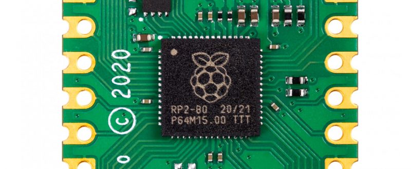
RP2040 at the heart of Raspberry Pi Pico
Microcontrollers are a huge yet largely unseen part of our modern lives. They are the hidden computers running most home appliances, gadgets, and toys. Pico and RP2040 were born of our desire to do for microcontrollers what we had done for computing with the larger Raspberry Pi boards. We wanted to create an innovative yet radically low-cost platform that was easy to use, powerful, yet flexible.
It became obvious that to stand out from the crowd of existing products in this space and to hit our cost and performance goals, we would need to build our own chip.
I and many of the Raspberry Pi engineering team have been involved in chip design in past lives, yet it took a long time to build a functional chip team from scratch. As well as requiring specialist skills, you need a lot of expensive tools and IP; and before you can buy these things, there is a lot of work required to evaluate and decide exactly which expensive goodies you’ll need. After a slow start, for the past couple of years we’ve had a small team working on it full-time, with many others pulled in to help as needed.
Low-cost and flexible
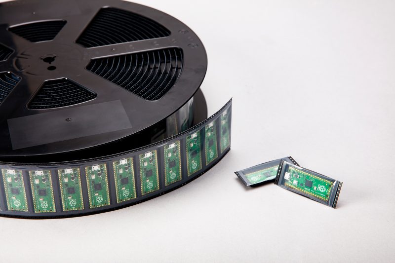
The Pico board was designed alongside RP2040 – in fact we designed the RP2040 pinout to work well on Pico, so we could use an inexpensive two-layer PCB, without compromising on the layout. A lot of thought has gone into making it as low-cost and flexible as possible – from the power circuitry to packaging the units on to Tape and Reel (which is cost-effective and has good packing density, reducing shipping costs).
“This ‘full stack’ design approach has allowed optimisation across the different parts”
With Pico we’ve hit the ‘pocket money’ price point, yet in RP2040 we’ve managed to pack in enough CPU performance and RAM to run more heavyweight applications such as MicroPython, and AI workloads like TinyML. We’ve also added genuinely new and innovative features such as the Programmable I/O (PIO), which can be programmed to ‘bit-bang’ almost any digital interface without using valuable CPU cycles. Finally, we have released a polished C/C++ SDK, comprehensive documentation and some very cool demos!
For me, this project has been particularly special as I began my career at a small chip-design startup. This was a chance to start from a clean sheet and design silicon the way we wanted to, and to talk about how and why we’ve done it, and how it works.
Pico is also our most vertically integrated product; meaning we control everything from the chip through to finished boards. This ‘full stack’ design approach has allowed optimisation across the different parts, creating a more cost-effective and coherent whole (it’s no wonder we’re not the only fruit company doing this).
And of course, it is designed here in Cambridge, birthplace of so many chip companies and computing pioneers. We’re very pleased to be continuing the Silicon Fen tradition.
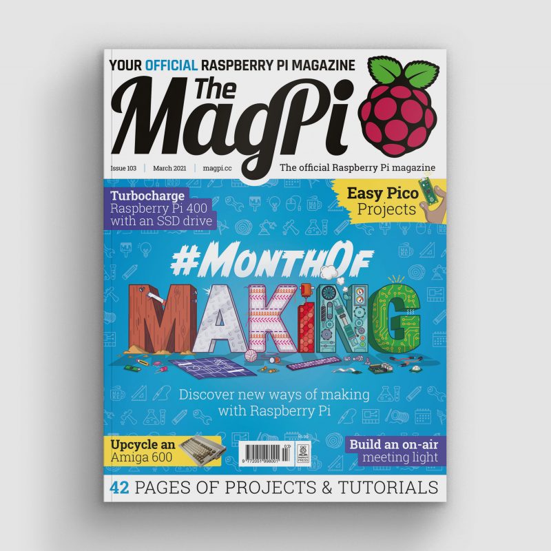
Get The MagPi 103 now
You can grab the brand-new issue right now online from the Raspberry Pi Press store, or via our app on Android or iOS. You can also pick it up from supermarkets and newsagents, but make sure you do so safely while following all your local guidelines.
Finally, there’s also a free PDF you can download. Good luck during the #MonthOfMaking, folks! I’ll see y’all online.
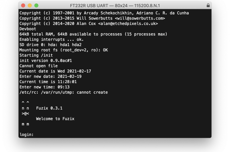
FUZIX is an old-school Unix clone that was initially written for the 8-bit Zilog Z80 processor and released by Alan Cox in 2014. At one time one of the most active Linux developers, Cox stepped back from kernel development in 2013. While the initial announcement has been lost in the mists because he made it on the now defunct Google+, Cox jokingly recommended the system for those longing for the good old days when all the source code still fitted on a single floppy disk.
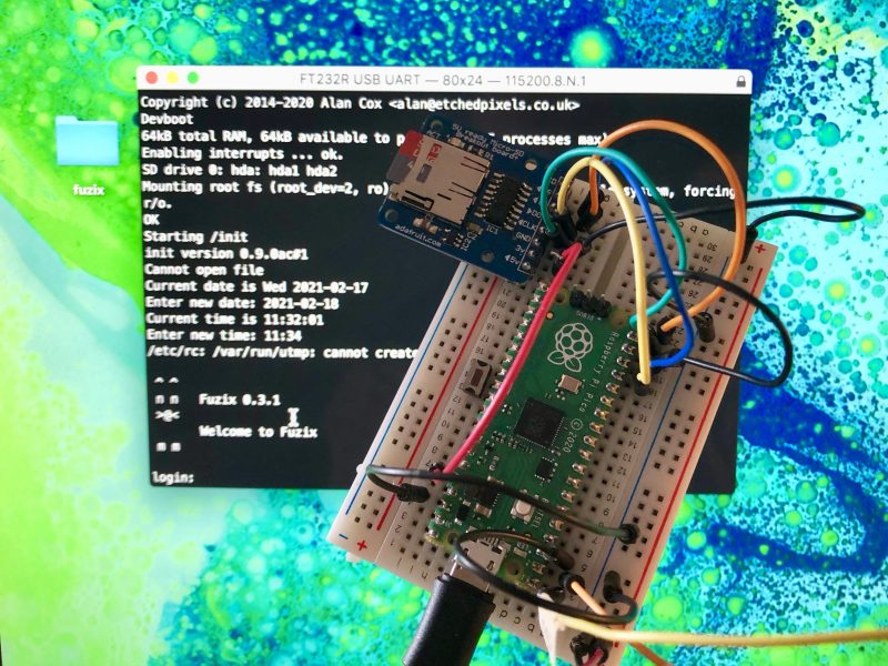
FUZIX running on Raspberry Pi Pico.
Since then FUZIX has been ported to other architectures such as 6502, 68000, and the MSP430. Earlier in the week David Given — who wrote both the MSP430 and ESP8266 ports — went ahead and ported it to Raspberry Pi Pico and RP2040.
FUZIX is a “proper” Unix with a serial console on Pico’s UART0 and SD card support, using the card both for the filesystem and for swap space. While there is a binary image available, it’s easy enough to build from source.
If you don’t already have the Raspberry Pi Pico toolchain set up and working you should go ahead and set up the C/C++ SDK.
Afterwards you need grab the the Pico port from GitHub.
and edit the first line of the Makefile to set the path to your pico-sdk.
So for instance if you’re building things on a Raspberry Pi and you’ve run the pico_setup.sh script, or followed the instructions in our Getting Started guide, you’d point the PICO_SDK_PATH to
export PICO_SDK_PATH = /home/pi/pico/pico-sdk
After that you can go ahead and build both the FUZIX UF2 file and the root filesystem.
$ make world -j
$ ./update-flash.sh
If everything goes well you should have a UF2 file in build/fuzix.uf2 and a filesystem.img image file in your current working directory.
You can now load the UF2 file onto your Pico in the normal way.
Go grab your Raspberry Pi Pico board and a micro USB cable. Plug the cable into your Raspberry Pi or laptop, then press and hold the BOOTSEL button on your Pico while you plug the other end of the micro USB cable into the board. Then release the button after the board is plugged in.
A disk volume called RPI-RP2 should pop up on your desktop. Double-click to open it, and then drag and drop the UF2 file into it.
The volume will automatically unmount, and your Pico is now running Unix. Unfortunately it won’t be much use without a filesystem.
Building a bootable SD card
The filesystem.img image file we built earlier isn’t a bootable image. Unlike the Raspberry Pi OS images you might be used to, you can’t just use something like Raspberry Pi Imager to write it to an SD card. We’re going to have to get our hands a bit dirtier than that.
The following instructions are for building your file system on a Raspberry Pi, or another similar Linux platform. Comparable tools are available on both MS Windows and Apple macOS, but the exact details will differ.
Go grab a microSD card. As the partitions we’re going to put onto it are only going to take up 34MB it doesn’t really matter what size you’ve got to hand. I was using a 4GB card, as that was the smallest I could find, but it’s not that important.
Now plug the card into a USB card reader and then into your Raspberry Pi or laptop computer. We’re going to have to build the partition table that FUZIX is expecting, which consists of two partitions: the first a 2MB swap partition, and the second a 32MB root partition into which we can copy the root filesystem, our filesystem.img file.
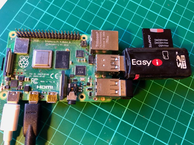
Raspberry Pi 4 with USB card reader.
After plugging your card into the reader you can find it from the command line using the lsblk command. If you’ve have a blank unformatted card it will be visible as /dev/sda.
$ lsblk
NAME        MAJ:MIN RM  SIZE RO TYPE MOUNTPOINT
sda           8:0    1  3.7G  0 disk
mmcblk0     179:0    0 14.9G  0 disk
├─mmcblk0p1 179:1    0  256M  0 part /boot
└─mmcblk0p2 179:2    0 14.6G  0 part /
$
But if the card is already formatted you might instead see something like this
$ lsblk
NAME        MAJ:MIN RM  SIZE RO TYPE MOUNTPOINT
sda           8:0    1  3.7G  0 disk
└─sda1        8:1    1  3.7G  0 part /media/pi/USB
mmcblk0     179:0    0 14.9G  0 disk
├─mmcblk0p1 179:1    0  256M  0 part /boot
└─mmcblk0p2 179:2    0 14.6G  0 part /
$
which is a FAT-formatted card with a MBR named “USB”, which your Raspberry Pi has automatically mounted under /media/pi/USB.
If your card has mounted, just go ahead and unmount it as follows:
$ umount /dev/sda1
Then looking using lsblk you should see
$ lsblk
NAME        MAJ:MIN RM  SIZE RO TYPE MOUNTPOINT
sda           8:0    1  3.7G  0 disk
└─sda1        8:1    1  3.7G  0 part
mmcblk0     179:0    0 14.9G  0 disk
├─mmcblk0p1 179:1    0  256M  0 part /boot
└─mmcblk0p2 179:2    0 14.6G  0 part /
$
at which point we can delete the current partition table by zeroing out the first part of the card and deleting the “start of disk” structures.
$ sudo dd if=/dev/zero of=/dev/sda bs=512 count=1
If you run lsblk again afterwards you’ll see that the sda1 partition has been deleted.
Next we’ll use fdisk to create a new partition table. Type the following
$ sudo fdisk /dev/sda
to put you at the fdisk prompt. Then type “o” to create a new DOS disklabel
Command (m for help): o
Created a new DOS disklabel with disk identifier 0x6e8481a2.
followed by “n” to create a new partition:
Command (m for help): n
Partition type
   p   primary (0 primary, 0 extended, 4 free)
   e   extended (container for logical partitions)
Select (default p): p
Partition number (1-4, default 1): 1
First sector (2048-7744511, default 2048): 2048
Last sector, +/-sectors or +/-size{K,M,G,T,P} (2048-7744511, default 7744511): +2M
Created a new partition 1 of type 'Linux' and of size 2 MiB.
Depending on the initial state of your disk you may be prompted that the partition “contains a vfat signature” and asked whether you want to remove the signature. If asked, just type “Y” to confirm.
Next, we’ll set the type for this partition to “7F“
Command (m for help): t
Selected partition 1
Hex code (type L to list all codes): 7F
Changed type of partition 'Linux' to 'unknown'.
to create the 2MB swap partition that FUZIX is expecting. From here we need to create a second 32MB partition to hold our root file system:
Command (m for help): n
Partition type
   p   primary (1 primary, 0 extended, 3 free)
   e   extended (container for logical partitions)
Select (default p): p
Partition number (2-4, default 2): 2
First sector (6144-7744511, default 6144): 6144
Last sector, +/-sectors or +/-size{K,M,G,T,P} (6144-7744511, default 7744511): +32M

Created a new partition 2 of type 'Linux' and of size 32 MiB.
Afterwards if you type “p” at the fdisk prompt you should see something like this:
Command (m for help): p
Disk /dev/sda: 3.7 GiB, 3965190144 bytes, 7744512 sectors
Disk model: STORAGE DEVICE
Units: sectors of 1 * 512 = 512 bytes
Sector size (logical/physical): 512 bytes / 512 bytes
I/O size (minimum/optimal): 512 bytes / 512 bytes
Disklabel type: dos
Disk identifier: 0xe121b9a3

Device     Boot Start   End Sectors Size Id Type
/dev/sda1        2048  6143    4096   2M 7f unknown
/dev/sda2        6144 71679   65536  32M 83 Linux
If you do, you can type “w” to write and save the partition table.
Finally, we can copy our root file system into our second 32MB partition:
$ sudo dd if=filesystem.img of=/dev/sda2
65535+0 records in
65535+0 records out
33553920 bytes (34 MB, 32 MiB) copied, 14.1064 s, 2.4 MB/s
$
You can now eject the SD card from the USB card reader, because it’s time to wire up our breadboard.
Wiring things up on the breadboard
If you’re developing on a Raspberry Pi, and you haven’t previously used UART serial — which is different from the “normal” USB serial — you should go read Section 4.5 of our Getting Started guide.
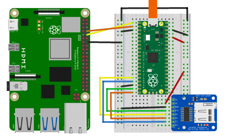
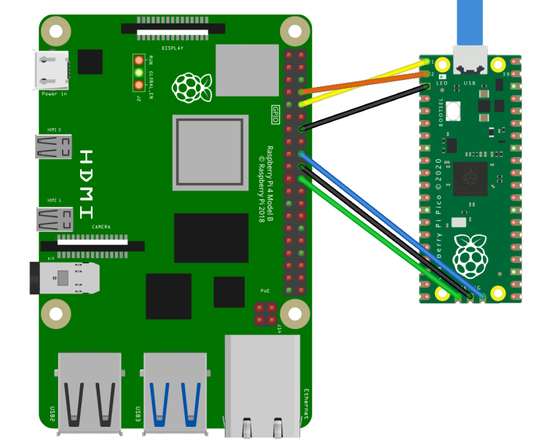
Connecting a Raspberry Pi to a Pico and SD card.
Here I’m using Adafruit’s MicroSD Card Breakout, and wiring the UART serial connection directly to to the Raspberry Pi’s serial port using the GPIO headers.
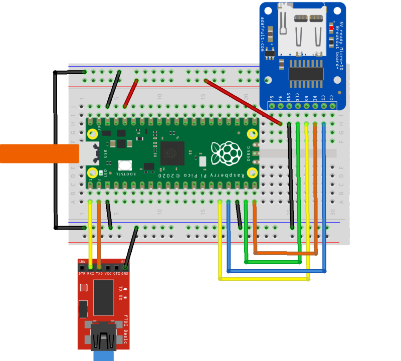
However, if you’re developing on a laptop you can use something like the SparkFun FTDI Basic Breakout to connect the serial UART to your computer. Again, see our Getting Started guide for details: Section 9.1.4 if you’re on Apple macOS, or Section 9.2.5 if you’re on MS Windows.
Connecting a laptop to a Pico and SD card.
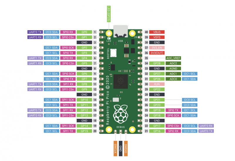
Either way, the mapping between the pins on your Raspberry Pi Pico and the SD card breakout is the same, and should be as follows:
Pico
RP2040
SD Card
3V3 (OUT)
—
+3.3V
Pin 16
GP12 (SPI1 RX)
DO (MISO)
Pin 17
GP13 (SPI1 CSn)
CS
Pin 18
GND
GND
Pin 19
GP14 (SPI1 SCK)
SCK
Pin 20
GP15 (SPI1 TX)
DI (MOSI)
Mapping between physical pin number, RP2040 pin, and SD Card breakout.
Once you’ve wired things up, pop your formatted microSD card into the breadboarded SD card breakout, and plug your Raspberry Pi Pico into USB power. FUZIX will boot automatically.
Connecting to FUZIX
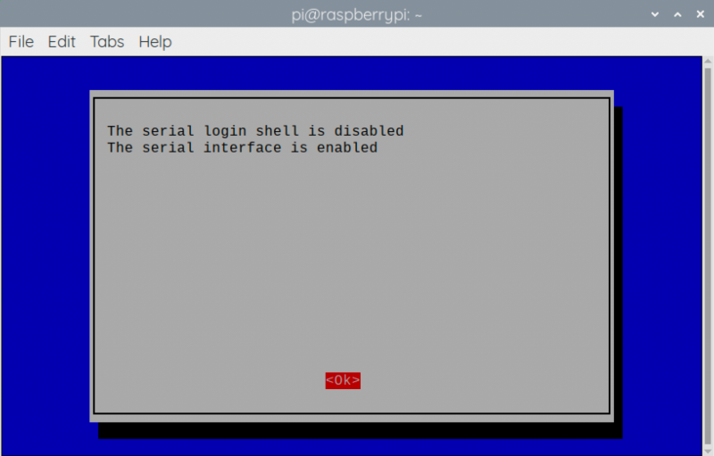
If you’re connecting using a Raspberry Pi, the first thing you’ll need to do is enable UART serial communications using raspi-config.
$ sudo raspi-config
Go to Interfacing Options → Serial. Select “No” when asked “Would you like a login shell to be accessible over serial?” and “Yes” when asked “Would you like the serial port hardware to be enabled?”
Enabling a serial UART using raspi-config on Raspberry Pi.
Leaving raspi-config you should choose “Yes” and reboot your Raspberry Pi to enable the serial port. More information about connecting via UART can be found in Section 4.5 of our Getting Started guide.
Alternatively, if you are working on a laptop from macOS or MS Windows you can use minicom, screen, or your usual Terminal program. If you’re unsure what to use, there are a number of options: for instance, a good option is CoolTerm, which is cross-platform and works on Linux, macOS, and Windows.
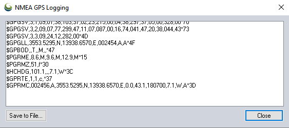
After connecting to the serial port you should see something like this:
If you don’t see anything, just unplug and replug your Pico to reset it and start FUZIX running again.
Finally, go ahead and enter the correct date and time, and when you get to the login prompt you can login as “root” with no password.
Welcome to FUZIX!
Wrapping up
While there are still a few problems, the port of FUZIX to Pico has been merged to the upstream repository, which means it’s now an official part of the operating system.
Support for developing for Pico can be found on the Raspberry Pi forums. There is also an (unofficial) Discord server where a lot of people active in the new community seem to be hanging out. Feedback on the documentation should be posted as an Issue to the pico-feedback repository on GitHub, or directly to the relevant repository it concerns.
All of the documentation, along with lots of other help and links, can be found on the Getting Started page. If you lose track of where that is in the future, you can always find it from your Pico: to access the page, just press and hold the BOOTSEL button on your Pico, plug it into your laptop or Raspberry Pi, then release the button. Go ahead and open the RPI-RP2 volume, and then click on the INDEX.HTM file.
In the latest issue of The MagPi Magazine, Alasdair Allan shares the secrets he had to keep while working behind the scenes to get Raspberry Pi’s RP2040 chip out into the world.
BEST friends
There is a new thing in the world, and I had a ringside seat for its creation.
For me, it started just over a year ago with a phone call from Eben Upton. One week later I was sitting in a meeting room at Raspberry Pi Towers in Cambridge, my head tilted to one side while Eben scribbled on a whiteboard and waved his hands around.
Eben had just told me that Raspberry Pi was designing its own silicon, and he was talking about the chip that would eventually be known as RP2040. Eben started out by drawing the bus fabric, which isn’t where you normally start when you talk about a new chip, but it turned out RP2040 was a rather unusual chip.
“I gradually drifted sideways into playing with the toys.”
I get bored easily. I started my career doing research into the high-energy physics of collision shocks in the accretion discs surrounding white dwarf stars, but I gradually drifted sideways into playing with the toys.
After spending some time working with agent-based systems to solve scheduling problems for robotic telescopes, I became interested in machine learning and what later became known as ‘big data’.
Meet Raspberry Pi Pico
From there, I spent time investigating the ‘data exhaust’ and data living outside the cloud in embedded and distributed devices, and as a consequence did a lot of work on mobile systems. Which led me to do some of the thinking, and work, on what’s now known as the Internet of Things. Which meant I had recently spent a lot of time writing and talking about embedded hardware.
Eben was looking for someone to make sure the documentation around Raspberry Pi Pico, and RP2040 silicon itself, was going to measure up. I took the job.
Rumour mill
I had spent the previous six months benchmarking Machine Learning (ML) inferencing on embedded hardware, and a lot of time writing and talking about the trendy new world of Tiny ML.
What is a microcontroller?
The rumours of what I was going to be doing for Raspberry Pi started flying on social media almost immediately. The somewhat pervasive idea that I was there to help support putting a Coral Edge TPU onto Raspberry Pi 5 was a particularly good wheeze.
Instead, I was going to spend the next year metaphorically locked in a room building a documentation toolchain around – and of course writing about – a totally secret product.
I couldn’t talk about it in public, and I talk about things in public a lot. Only the fact that almost everyone else spent the next year locked indoors as well kept too many questions from being asked. I didn’t have to tell conference organisers that I couldn’t talk about what I was doing, because there weren’t any conferences to organise.
I’m rather pleased with what I’ve done with my first year at Raspberry Pi, and of course with how my work on RP2040 and Raspberry Pi Pico turned out.
Much like a Raspberry Pi is an accessible computer that gives you everything you need to learn to write a program, RP2040 is an accessible chip with everything you need to learn to build a product. It’s going to bring a big change to the microcontroller market, and I’m really rather pleased I got a ringside seat to its creation.
When I first joined Raspberry Pi as a software engineer four and a half years ago, I didn’t know anything about chip design. I thought it was magic. This blog post looks at the journey to Raspberry Silicon and the design process of RP2040.
RP2040 – the heart of Raspberry Pi Pico
RP2040 has been in development since summer 2017. Chips are extremely complicated to design. In particular, the first chip you design requires you to design several fundamental components, which you can then reuse on future chips. The engineering effort was also diverted at some points in the project (for example to focus on the Raspberry Pi 4 launch).
Once the chip architecture is specified, the next stage of the project is the design and implementation, where hardware is described using a hardware description language such as Verilog. Verilog has been around since 1984 and, along with VHDL, has been used to design most chips in existence today. So what does Verilog look like, and how does it compare to writing software?
Suppose we have a C program that implements two wrapping counters:
void count_forever(void) {
    uint8_t i = 0;
    uint8_t j = 0;
    while (1) {
        i += 1;
        j += 1;
    }
}
This C program will execute sequentially line by line, and the processor won’t be able to do anything else (unless it is interrupted) while running this code. Let’s compare this with a Verilog implementation of the same counter:
module counter (
    input wire clk,
    input wire rst_n,
    output reg [7:0] i,
    output reg [7:0] j
);

always @ (posedge clk or negedge rst_n) begin
    if (~rst_n) begin
        // Counter is in reset so hold counter at 0
        i <= 8’d0;
        j <= 8’d0;
    end else begin
        i <= i + 8’d1;
        j <= j + 8’d1;
    end
end

endmodule
Verilog statements are executed in parallel on every clock cycle, so both i and j are updated at exactly the same time, whereas the C program increments i first, followed by j. Expanding on this idea, you can think of a chip as thousands of small Verilog modules like this, all executing in parallel.
A chip designer has several tools available to them to test the design. Testing/verification is the most important part of a chip design project: if a feature hasn’t been tested, then it probably doesn’t work. Two methods of testing used on RP2040 are simulators and FPGAs.
A simulator lets you simulate the entire chip design, and also some additional components. In RP2040’s case, we simulated RP2040 and an external flash chip, allowing us to run code from SPI flash in the simulator. That is the beauty of hardware design: you can design some hardware, then write some C code to test it, and then watch it all run cycle by cycle in the simulator.
“ell” from the phrase “Hello World” from core0 of RP2040 in a simulator
The downside to simulators is that they are very slow. It can take several hours to simulate just one second of a chip. Simulation time can be reduced by testing blocks of hardware in isolation from the rest of the chip, but even then it is still slow. This is where FPGAs come in…
FPGAs (Field Programmable Gate Arrays) are chips that have reconfigurable logic, and can emulate the digital parts of a chip, allowing most of the logic in the chip to be tested.
FPGAs can’t emulate the analogue parts of a design, such as the resistors that are built into RP2040’s USB PHY. However, this can be approximated by using external hardware to provide analogue functionality. FPGAs often can’t run a design at full speed. In RP2040’s case, the FPGA was able to run at 48MHz (compared to 133MHz for the fully fledged chip). This is still fast enough to test everything we wanted and also develop software on.
FPGAs also have debug logic built into them. This allows the hardware designer to probe signals in the FPGA, and view them in a waveform viewer similar to the simulator above, although visibility is limited compared to the simulator.
Graham’s tidy FPGAGraham’s less tidy FPGAOh dear
The RP2040 bootrom was developed on FPGA, allowing us to test the USB boot mode, as well executing code from SPI flash. In the image above, the SD card slot on the FPGA is wired up to SPI flash using an SD card-shaped flash board designed by Luke Wren.
USB testing on FPGA
In parallel to Verilog development, the implementation team is busy making sure that the Verilog we write can actually be made into a real chip. Synthesis takes a Verilog description of the chip and converts the logic described into logic cells defined by your library choice. RP2040 is manufactured by TSMC, and we used their standard cell library.
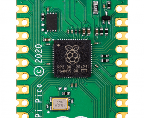
RP2040 silicon in a DIL package!
Chip manufacturing isn’t perfect. So design for test (DFT) logic is inserted, allowing the logic in RP2040 to be tested during production to make sure there are no manufacturing defects (short or open circuit connections, for example). Chips that fail this production test are thrown away (this is a tiny percentage – the yield for RP2040 is particularly high due to the small die size).
After synthesis, the resulting netlist goes through a layout phase where the standard cells are physically placed and interconnect wires are routed. This is a synchronous design so clock trees are inserted, and timing is checked and fixed to make sure the design meets the clock speeds that we want. Once several design rules are checked, the layout can be exported to GDSII format, suitable for export to TSMC for manufacture.
RP2040 chips ready for a bring up board
(In reality, the process of synthesis, layout, and DFT insertion is extremely complicated and takes several months to get right, so the description here is just a highly abbreviated overview of the entire process.)
Once silicon wafers are manufactured at TSMC they need to be put into a package. After that, the first chips are sent to Pi Towers for bring-up!
The RP2040 bring-up board
A bring-up board typically has a socket (in the centre) so you can test several chips in a single board. It also separates each power supply on the chip, so you can limit the current on first power-up to check there are no shorts. You don’t want the magic smoke to escape!
The USB boot mode working straight out of the box on a bring-up board!
Once the initial bring-up was done, RP2040 was put through its paces in the lab. Characterising behaviour, seeing how it performs at temperature and voltage extremes.
Once the initial batch of RP2040s are signed off we give the signal for mass production, ready for them to be put onto Pico boards that you have in your hands today.
82K RP2040s ready for shipment to Sony
A chip is useless without detailed documentation. While RP2040 was making its way to mass production, we spent several months writing the SDK and excellent documentation you have available to you today.
Dave Akerman of High Altitude Ballooning came up with a stratospherically cool application for Raspberry Pi Pico. In this guest blog, he shows you how to build and code a weather balloon tracker.
Balloon tracking
My main hobby is flying weather balloons, using GPS/radio trackers to relay their position to the ground, so they can be tracked and hopefully recovered. Trackers minimally consist of a GPS receiver feeding the current position to a small computer, which in turn controls a radio transmitter to send that position to the ground. That position is then fed to a live map to aid chasing and recovering the flight.
How it all works
This essential role of the tracker computer is thus a simple one, and those making their own trackers can choose from a variety of microcontrollers chips and boards, for example Arduino boards, PIC microcontrollers or the BBC Microbit. Anything with a modest amount of code memory, data memory, processor power and I/O (serial, SPI etc depending on choice of GPS and radio) will do. A popular choice is Raspberry Pi, which, whilst a sledgehammer to crack a nut for tracking, does make it easy to add a camera.
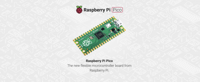
Raspberry Pi Pico
When I see a new type of processor board, I feel duty bound to make it into a balloon tracker, so when I was asked to help test the new Raspberry Pi Pico, doing so was my first thought. It has plenty of I/O – SPI ports, I2C and serial all available – plus a unique ability (not that I need it for now) to add extra peripherals using the programmable PIO modules, so there was no doubt that it would be very usable. Also, having much more memory than typical microcontrollers, it offers the ability to add functions that would normally need a full Raspberry Pi board – for example on-board landing prediction. More on that later.
Tracker components
So a basic tracker has a GPS receiver and radio transmitter. To connect these to the Raspberry Pi Pico, I used a prototyping board where I mounted a UBlox GPS receiver, LoRa radio transmitter, and sockets for the Pico itself.
I don’t use breadboards as they are prone to intermittent connections that then waste programming time chasing a “bug” that’s actually a hardware problem. Besides, trackers need to be robust so I would need to solder one together eventually anyway.
Pico top, GPS bottom-left; LoRa bottom-right
The particular UBlox GPS module I had handy only has a serial port brought out, so I couldn’t use I2C. No matter because, unlike most Arduino boards, the Raspberry Pi Pico isn’t limited to a single serial port.
The LoRa module connects via SPI and a single GPIO pin which the module uses to send its status (e.g. packet sent – ready to send next packet) to the Raspberry Pi Pico.
Finally, with the tracker working, I added an I2C environmental sensor to the board via a pin header, so the sensor can be placed in free air outside the tracker.
Finally, with the tracker working, I added an I2C environmental sensor to the board via a pin header, so the sensor can be placed in free air outside the tracker.
Development setup
I decided to use C for my tracker rather than Python, for a variety of reasons. The main one is that I have plenty of existing C tracker code to work from, for Arduino and Raspberry Pi, but not so much Python. Secondly, I figured that most of the testers would be using Python so there might be more of a need to test the C toolchain.
The easiest route to getting the C/C++ toolchain working is to install on a Raspberry Pi 4. I couldn’t quite get the VSCode integration working (finger trouble I think) but anyway I’m quite happy to code with an editor and separate build window. So what I ended up with was Notepadd++ on my Windows PC to edit the code, with the source on a Raspberry Pi 4. I then had an ssh window open to run the compile/link steps, and a separate one running the debugger. The debugger downloads the binary to the Raspberry Pi Pico via the latter’s debug port.
For regular debug output from the program I connected a Raspberry Pi Pico serial port to an FTDI USB Serial TTL adapter connected back to my PC – see the image below.
At some point I’ll revisit this setup. First, it’s now possible to printf to a virtual USB serial port, so that frees up that Raspberry Pi Pico serial port. Secondly, I need to get that VSCode integration working.
Tracker code
My Raspberry Pi and Arduino tracker programs work slightly differently. On the Raspberry Pi, to separate the code for the different functions (GPS, radio, sensors etc) I use a separate thread for each. That allows for example a new packet to be sent to the radio transmitter without delay, even if a slow operation is running concurrently elsewhere.
On the Arduino, with no threads available, the code is still split into separate modules but each one is coded to run quickly without waiting in a loop for a peripheral to respond. For example some temperature sensors can take a second or so to take a measurement, and it’s vital not to sit in a loop waiting for the result.
The C toolchain for Raspberry Pi Pico doesn’t, by default, support threaded code unfortunately. Rather than rebuild it with support added, I opted for the approach I use with Arduino. So the main code starts with initialising each module individually, and then sits in a tight loop calling each module once per loop. It’s then up to each module to return control swiftly so that the loop keeps running quickly and no module is kept waiting for long.
Code modules
The GPS code uses a serial port to receive NMEA data from the GPS. NMEA is the standard ASCII protocol used by pretty much every GPS module that exists, and includes the current date, time, latitude, longitude, altitude and other data. All we need to do is confirm that the data is valid, then read and store these key values. The other important function is to ensure that the GPS module is in the correct “flight mode” so that it works at high altitude – without this then it will stop providing new positions about 18km altitude.
The LoRa radio code checks to see when the module is not transmitting, then builds a new telemetry message containing the above GPS data plus the name of the balloon, any other sensor data, and the landing prediction (see later).
This message is passed to the LoRa chip via SPI, then the chip switches on its radio and modulates the radio signal with the telemetry data. Once the message has been sent then the chip switches on its DIO0 output which is connected to the Raspberry Pi Pico so it knows when it can send another message.
All messages are received on the ground (in this case by a Pi LoRa receiver) and then uploaded to an internet database that in turn drives a live Google map (see image below).
Sensors
Usefully for balloon trackers, the Raspberry Pi Pico can be powered directly from battery via an on-board buck-boost converter.
The input voltage connects through a potential divider to an analog sense input (ADC3) to allow for easy measurement of the battery voltage. Note that the ADC reference voltage is the 3.3V rail, which is noisy especially when used to power external devices such as the GPS and LoRa both of which have rather spiky power consumption requirements, so the code averages out many measurements.
An alternative would be to add a precise reference voltage to the ADC but I went for the zero cost software option.
The board temperature can also be measured, this time using ADC4. That’s less useful though for a tracker than an external temperature measurement, so I added a BME280 device for that. The Raspberry Pi Pico samples include code for the BME connected via SPI, but I chose I2C so I needed to replace the SPI calls with I2C calls. Pretty easy. The BME280 returns pressure – probably the most interesting environmental measurement for a balloon tracker – and humidity too.
Landing prediction
So far, everything I’ve done could also be done on a basic AVR chip e.g. the Arduino Mini Pro, with some spare room. However, one very useful extra is to add a prediction of the landing point.
We use online flight prediction prior to launch, to determine roughly where the balloon will land (within a few miles) so we know it’s safe to launch without landing near a city for example. This uses a global wind prediction database plus some flight parameters (e.g. ascent rate and burst altitude) to predict the path of the balloon from launch to landing. It can be very accurate if those parameters are followed through on the flight itself.
Of course the actual flight never quite follows the plan – for example the launch might be later than planned, and in changing wind conditions that itself can move the landing point by miles. So it’s useful to have a live prediction during that flight, and indeed we have that, using the same wind database.
However, since it’s online, and 3G/4G can be patchy when chasing a balloon, it’s useful to have an independent landing prediction. This can be done in the tracker itself, by storing the wind speed and direction (deduced from GPS positions) on the way up, measuring the descent rate after burst, applying that to an atmospheric density model to plot the future descent rate to the ground, and then calculating the effect of the wind during descent and finally producing a landing position.
Typical Arduino boards don’t have enough memory to store the measured wind data, but the Raspberry Pi Pico has more than enough. I ported my existing code which:
During ascent, it splits the vertical range into 100 metres sections, into which it stores the latitude and longitude deltas as degrees per second.
Every few seconds, it runs a prediction of the landing position based on the current position, the data in that array, and an estimated descent profile that uses a simple atmospheric model plus default values for payload weight and parachute effectiveness.
During descent, the parachute effectiveness is measured, and the actual figure is used in the above calculation in (2).
Calculates the time it will spend within each 100m section of air, then multiplies that by the stored wind speed to calculate the horizontal distance and direction it is expected to travel in that section.
Adds all those sectional movements together, adds those to the current position, and produces the landing prediction.
Sends that position down to the ground with the rest of the telemetry.
Phew. Now we know pretty much everything about how balloon trackers work. Thanks Dave! Also, if you want to go on your own near-space flight, check out High Altitude Ballooning.
We’ve tried to make it as easy as possible for you to load your code onto your new Raspberry Pi Pico: press and hold the BOOTSEL button, plug your Pico into your computer, and it’ll mount as a mass storage volume. Then just drag and drop a UF2 file onto the board.
However, not everybody is keen to keep unplugging their micro USB cable every time they want to upload a UF2 onto the board. Don’t worry — there’s more than one way around that problem.
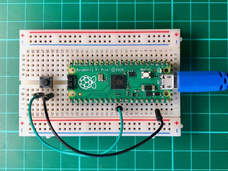
Raspberry Pi Pico with a reset button wired to the GND and RUN pins
Firstly, if you’re developing in MicroPython there isn’t any real need to unplug and replug Pico to write code. The only time you’ll need to do it is the initial upload of the MicroPython firmware, which comes as a UF2. From there on in, you’re talking to the board via the REPL and a serial connection, either in Thonny or some other editor.
However, if you’re developing using our C SDK, then to upload new code to your Pico you have to upload a new UF2. This means you’ll need to unplug and replug the board to put Pico into BOOTSEL mode each time you make a change in your code and want to test it.
No more unplugging with SWD?
The best way around this is to use SWD mode (see Chapter 5 of our C/C++ Getting Started book) to upload code using the debug port, instead of using mass storage (BOOTSEL) mode.
A Raspberry Pi 4 and Raspberry Pi Pico with UART and SWD ports connected together
This gets you debugger support, which is invaluable while developing, and involves adding just three more wires. Afterwards, you’ll never have to unplug your Pico again.
Keep on dragging and dropping
But if you want to stick with uploading by drag-and-drop, adding a reset button to your Raspberry Pi Pico is pretty easy.
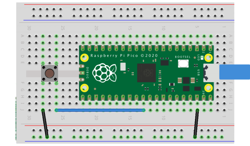
Raspberry Pi Pico with a reset button wired to the GND and RUN pins
All you need to do is to wire the GND and RUN pins together and add an extra momentary contact button to your breadboard. Pushing the button will reset the board.
Then, instead of unplugging and replugging the USB cable when you want to load code onto Pico, you push and hold the RESET button, push the BOOTSEL button, release the RESET button, then release the BOOTSEL button.
Entering BOOTSEL mode without unplugging your Pico
If your board is in BOOTSEL mode and you want to start code you’ve already loaded running again, all you have to do now is briefly push the RESET button.
Leaving BOOTSEL mode without unplugging your Pico.
We’ve see some people use the 3V3_EN pin instead of the RUN pin. While it’ll work in a pinch, the problem with disabling 3.3V is that GPIOs that are driven from powered external devices will leak like crazy while 3.3V is disabled. There is even the possibility of damage to the chip. So it’s much better to use the RUN pin to make a reset button than the 3V3_EN pin.
What about the other button?
As an aside, if you want to break out the BOOTSEL button as well — perhaps you’re intending to bury your Pico inside an enclosure — you can use TP6 (that is, Test Point 6) on the rear of the board to do so. See Chapter 2 of the Pico Datasheet for details.
Where to find more help and information
Support for developing for Pico can be found on the Raspberry Pi forums. There is also an (unofficial) Discord server where a lot of people active in the new community seem to be hanging out. Feedback on the documentation should be posted as an issue to the pico-feedback repository on GitHub, or directly to the relevant repository it concerns.
All of the documentation, along with lots of other help and links, can be found on the same Getting Started page from which we grabbed our original UF2 file.
If you lose track of where that is in the future, you can always find it from your Pico: to access the page, just press and hold the BOOTSEL button on your Pico, plug it into your laptop or Raspberry Pi, then release the button. Go ahead and open the RPI-RP2 volume, and then click on the INDEX.HTM file.
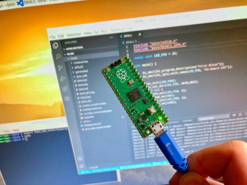
The new Raspberry Pi Pico is very different from a traditional Raspberry Pi. Pico is a microcontroller, rather than a microcomputer. Unlike a Raspberry Pi it’s a platform you develop for, not a platform you develop on.
Blinking the onboard LED
But you still have choices if you want to develop for Pico, because there is both a C/C++ SDK and an official MicroPython port. Beyond that there are other options opening up, with a port of CircuitPython from Adafruit and the prospect of Arduino support, or even a Rust port.
Here I’m going to talk about how to get started with the C/C++ SDK, which lets you develop for Raspberry Pi Pico from your laptop or Raspberry Pi.
I’m going to assume you’re using a Raspberry Pi; after all, why wouldn’t you want to do that? But if you want to develop for Pico from your Windows or Mac laptop, you’ll find full instructions on how to do that in our Getting Started guide.
Blinking your first LED
When you’re writing software for hardware, the first program that gets run in a new programming environment is typically turning an LED on, off, and then on again. Learning how to blink an LED gets you halfway to anywhere. We’re going to go ahead and blink the onboard LED on Pico, which is connected to pin 25 of the RP2040 chip.
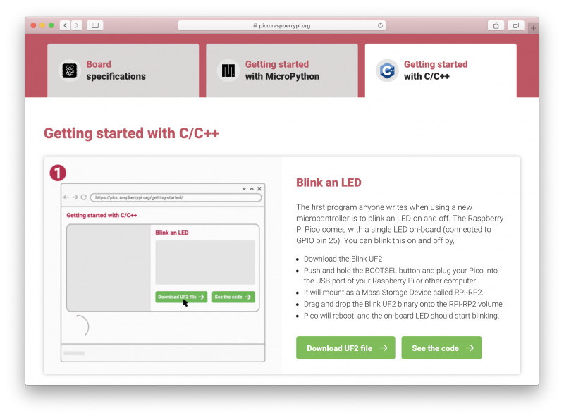
We’ve tried to make getting started with Raspberry Pi Pico as easy as possible. In fact, we’ve provided some pre-built binaries that you can just drag and drop onto your Raspberry Pi Pico to make sure everything is working even before you start writing your own code.
Go to the Getting Started page and click on the “Getting started with C/C++” tab, then the “Download UF2 file” button in the “Blink an LED” box.
A file called blink.uf2 will be downloaded to your computer. Go grab your Raspberry Pi Pico board and a micro USB cable. Plug the cable into your Raspberry Pi or laptop, then press and hold the BOOTSEL button on your Pico while you plug the other end of the micro USB cable into the board. Then release the button after the board is plugged in.
A disk volume called RPI-RP2 should pop up on your desktop. Double-click to open it, and then drag and drop the UF2 file into it. The volume will automatically unmount and the light on your board should start blinking.
Blinking an LED
Congratulations! You’ve just put code onto your Raspberry Pi Pico for the first time. Now we’ve made sure that we can successfully get a program onto the board, let’s take a step back and look at how we’d write that program in the first place.
Getting the SDK
Somewhat unsurprisingly, we’ve gone to a lot of trouble to make installing the tools you’ll need to develop for Pico as easy as possible on a Raspberry Pi. We’re hoping to make things easier still in the future, but you should be able to install everything you need by running a setup script.
However, before we do anything, the first thing you’ll need to do is make sure your operating system is up to date.
$ sudo apt update
$ sudo apt full-upgrade
Once that’s complete you can grab the setup script directly from Github, and run it at the command line.
The script will do a lot of things behind the scenes to configure your Raspberry Pi for development, including installing the C/C++ command line toolchain and Visual Studio Code. Once it has run, you will need to reboot your Raspberry Pi.
$ sudo reboot
The script has been tested and is known to work from a clean, up-to-date installation of Raspberry Pi OS. However, full instructions, along with instructions for manual installation of the toolchain if you prefer to do that, can be found in the “Getting Started” guide.
Once your Raspberry Pi has rebooted we can get started writing code.
Writing code for your Pico
There is a large amount of example code for Pico, and one of the things that the setup script will have done is to download the examples and build both the Blink and “Hello World” examples to verify that your toolchain is working.
But we’re going to go ahead and write our own.
We’re going to be working in the ~/pico directory created by the setup script, and the first thing we need to do is to create a directory to house our project.
$ cd pico
$ ls -la
total 59284
drwxr-xr-x  9 pi pi     4096 Jan 28 10:26 .
drwxr-xr-x 19 pi pi     4096 Jan 28 10:29 ..
drwxr-xr-x 12 pi pi     4096 Jan 28 10:24 openocd
drwxr-xr-x 28 pi pi     4096 Jan 28 10:20 pico-examples
drwxr-xr-x  7 pi pi     4096 Jan 28 10:20 pico-extras
drwxr-xr-x 10 pi pi     4096 Jan 28 10:20 pico-playground
drwxr-xr-x  5 pi pi     4096 Jan 28 10:21 picoprobe
drwxr-xr-x 10 pi pi     4096 Jan 28 10:19 pico-sdk
drwxr-xr-x  7 pi pi     4096 Jan 28 10:22 picotool
-rw-r--r--  1 pi pi 60667760 Dec 16 16:36 vscode.deb
$ mkdir blink
$ cd blink
Now open up your favourite editor and create a file called blink.c in the blink directory.
Then copy the pico_sdk_import.cmake file from the external folder in your pico-sdk installation to your test project folder.
$ cp ../pico-sdk/external/pico_sdk_import.cmake .
You should now have something that looks like this:
$ ls -la
total 20
drwxr-xr-x  2 pi pi 4096 Jan 28 11:32 .
drwxr-xr-x 10 pi pi 4096 Jan 28 11:01 ..
-rw-r--r--  1 pi pi  398 Jan 28 11:06 blink.c
-rw-r--r--  1 pi pi  211 Jan 28 11:32 CMakeLists.txt
-rw-r--r--  1 pi pi 2721 Jan 28 11:32 pico_sdk_import.cmake
$
We are ready to build our project using CMake.
$ mkdir build
$ cd build
$ export PICO_SDK_PATH=../../pico-sdk
$ cmake ..
$ make
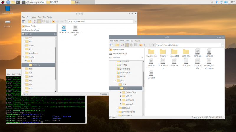
If all goes well you should see a whole bunch of messages flash past in your Terminal window and a number of files will be generated in the build/ directory, including one called blink.uf2.
Just as we did before with the UF2 file we downloaded from the Getting Started page, we can now drag and drop this file on to our Pico.
Unplug the cable from your Pico, then press and hold the BOOTSEL button on your Pico and plug it back in. Then release the button after the board is plugged in.
The new blink.uf2 binary can be dragged and dropped on to our Pico
The RPI-RP2 disk volume should pop up on your desktop again. Double-click to open it, then open a file viewer in the pico/blink/build/ directory and drag and drop the UF2 file you’ll find there on to the RPI-RP2 volume. It will automatically unmount, and the light on your board should start blinking. But this time it will blink a little bit differently from before.
Try playing around with the sleep_ms( ) lines in our code to vary how much time there is between blinks. You could even take a peek at one of the examples, which shows you how to blink the onboard LED in Morse code.
Using Picotool
One way to convince yourself that the program running on your Pico is the one we just built is to use something called picotool. Picotool is a command line utility installed by the setup script that is a Swiss Army knife for all things Pico.
Go ahead and unplug your Pico from your Raspberry Pi, press and hold the BOOTSEL button, and plug it back in. Then run picotool.
$ sudo picotool info -a
Program Information
 name:          blink
 description:   First Blink
 binary start:  0x10000000
 binary end:    0x10003344

Fixed Pin Information
 25:  On-board LED

Build Information
 sdk version:       1.0.0
 pico_board:        pico
 build date:        Jan 28 2021
 build attributes:  Release

Device Information
 flash size:   2048K
 ROM version:  1
$
You’ll see lots of information about the program currently on your Pico. Then if you want to start it blinking again, just unplug and replug Pico to leave BOOTSEL mode and start your program running once more.
Picotool can do a lot more than this, and you’ll find more information about it in Appendix B of the “Getting Started” guide.
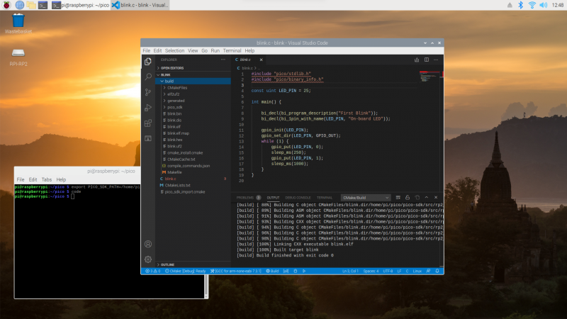
Using Visual Studio Code
So far we’ve been building our Pico projects from the command line, but the setup script also installed and configured Visual Studio Code, and we can build the exact same CMake-based project in the Visual Studio Code environment. You can open it as below:
$ cd ~/pico
$ export PICO_SDK_PATH=/home/pi/pico/pico-sdk
$ code
Chapter 6 of the Getting Started guide has full details of how to load and compile a Pico project inside Visual Studio Code. If you’re used to Visual Studio Code, you might be able to make your way from here without much extra help, as the setup script has done most of the heavy lifting for you in configuring the IDE.
What’s left is to open the pico/blink folder and allow the CMake Tools extension to configure the project. After selecting arm-none-eabi as your compiler, just hit the “Build’ button in the blue bottom bar.
Building our blink project inside Visual Studio Code
While we recommend and support Visual Studio Code as the development environment of choice for developing for Pico — it works cross-platform under Linux, Windows, and macOS and has good plugin support for debugging — you can also take a look at Chapter 9 of the Getting Started guide. There we talk about how to use both Eclipse and CLion to develop for Pico, and if you’re more used to those environments you should be able to get up and running in either without much trouble.
Where now?
If you’ve got this far, you’ve built and deployed your very first C program to your Raspberry Pi Pico. Well done! The next step is probably going to be saying “Hello World!” over serial back to your Raspberry Pi.
From here, you probably want to sit down and read the Getting Started guide I’ve mentioned throughout the article, especially if you want to make use of SWD debugging, which is discussed at length in the guide. Beyond that I’d point you to the book on the C/C++ SDK which has the API-level documentation, as well as a high-level discussion of the design of the SDK.
Support for developing for Pico can be found on the Raspberry Pi forums. There is also an (unofficial) Discord server where a lot of people active in the new community seem to be hanging out. Feedback on the documentation should be posted as an Issue to the pico-feedback repository on Github, or directly to the relevant repository it concerns.
All of the documentation, along with lots of other help and links, can be found on the same Getting Started page from which we grabbed our original UF2 file.
If you lose track of where that is in the future, you can always find it from your Pico: to access the page, just press and hold the BOOTSEL button on your Pico, plug it into your laptop or Raspberry Pi, then release the button. Go ahead and open the RPI-RP2 volume, and then click on the INDEX.HTM file.
Look at our lovely friends over at This is not Rocket Science (TiNRS) – they’ve wasted no time at all in jumping in with our new chips. In this guest post, Stijn of TiNRS shares their fishily musical application of our new toy.
The new RP2040 chip by Raspberry Pi is amazing. When we got our hands on this beautiful little thing, we did what we always do with new chips and slapped on a Goldfish, our favourite acid bassline synthesiser (we make fish and chips, hahahaha).
TiNRS took to Instagram to explain more about the 18 year old fish synthesiser project
While benchmarking the performance by copy/pasting instances of our entire Goldfish in search of the chip’s limits, we suddenly found ourselves with a polyphonic synth. We have since rewritten these multiple instances into a 16-voice Poly-Goldfish with 4 oscillators per voice. To celebrate we designed a PCB and brightly coloured frontpanel to give this new Goldfish some dedicated controls.
Bring-up was trivial due to the amazing documentation and the extremely flexible PIO-blocks. RP2040 is a dream to work with. Childlike giddiness ensued while lying on the carpet and programming in VSCode on a Raspberry Pi 400 talking directly to the RP2040. This is the way to release a chip into the world: with fantastic documentation, an open toolchain and plenty of examples of how to use everything.
PCB and brightly coloured front panel
Once these chips hit general availability we will probably share some designs on our Github. This chip is now part of our go-to set of tools to make cool stuff and will very bloody likely be inside our next three modules.
It fits perfectly in our Open Source attitude. Because of the easy, high quality, multi-platform, free and even beginner-friendly toolchain they have built around this chip, we can expand the accessibility to the insides of our designs. With these chips it is way easier for us to have you do things like adding your own algorithms, building extra modes or creating personal effects. We can lean on the quality of the Raspberry Pi platform and this amazing chip.
TiNRS approves.
Keep an eye on the TiNR blog for more adventures in technology. You can also find them on Twitter @rocket_not and on Instagram.
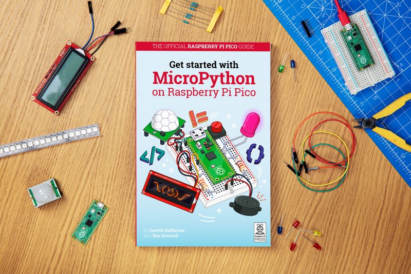
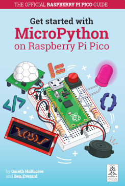
So, you’ve got a brand new Raspberry Pi Pico and want to know how to get started with this tiny but powerful microcontroller? We’ve got just the book for you.
Beginner-friendly
In Get Started with MicroPython on Raspberry Pi Pico, you’ll learn how to use the beginner-friendly language MicroPython to write programs and connect hardware to make your Raspberry Pi Pico interact with the world around it. Using these skills, you can create your own electro-mechanical projects, whether for fun or to make your life easier.
After taking you on a guided tour of Pico, the books shows you how to get it up and running with a step-by-step illustrated guide to soldering pin headers to the board and installing the MicroPython firmware via a computer.
Programming basics
Next, we take you through the basics of programming in MicroPython, a Python-based programming language developed specifically for microcontrollers such as Pico. From there, we explore the wonderful world of physical computing and connect a variety of electronic components to Pico using a breadboard. Controlling LEDs and reading input from push buttons, you’ll start by creating a pedestrian crossing simulation, before moving on to projects such as a reaction game, burglar alarm, temperature gauge, and data logger.
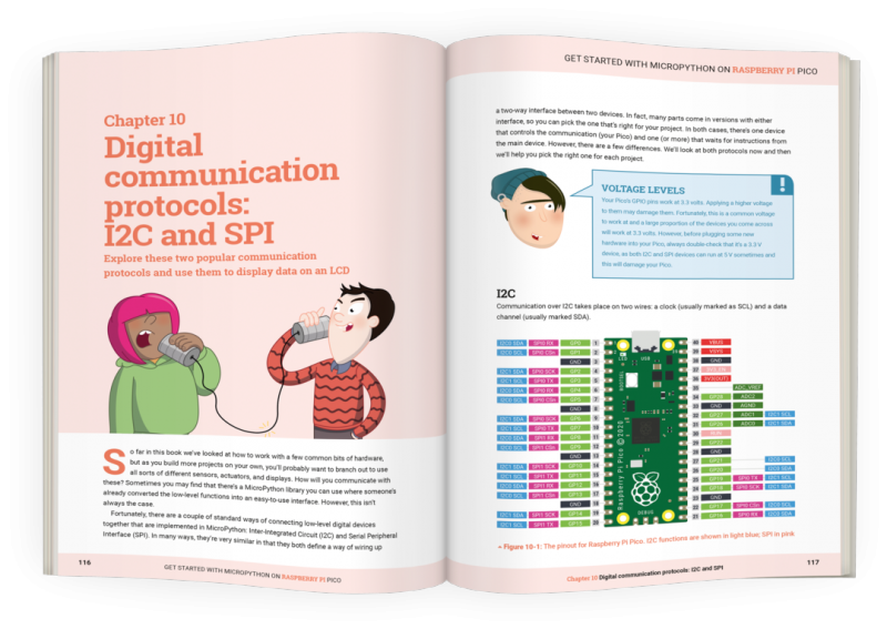
Raspberry Pi Pico also supports the I2C and SPI protocols for communicating with devices, which we explore by connecting it up to an LCD display. You can even use MicroPython to take advantage of one of Pico’s most powerful features, Programmable I/O (PIO), which we explore by controlling NeoPixel LED strips.
Get your copy today!
You can buy Get Started with MicroPython on Raspberry Pi Pico now from the Raspberry Pi Press online store. If you don’t need the lovely new book, with its new-book smell, in your hands in real life, you can download a PDF version for free (or a small voluntary contribution).
STOP PRESS: we’ve spotted an error in the first print run of the book, affecting the code examples in Chapters 4 to 7. We’re sorry! Fortunately it’s easy for readers to correct in their own code; see here for everything you need to know. We’ve already corrected this in the PDF version.
The best part of launching a new product is seeing the reaction of the Raspberry Pi community. When we released Raspberry Pi Pico into the world last Thursday, it didn’t take long for our curious, creative crew of hackers and tinkerers to share some brilliant videos, blogs and photos.
If you’ve spotted other cool stuff people have done with Raspberry Pi Pico, do comment with a link at the end of this post so we can check it out.
Graham Sanderson’s BBC Micro emulation
YouTube went wild for this Raspberry Pi Pico-powered BBC Micro and BBC Master emulation. Graham Sanderson‘s little bit of fun with our latest creation emulates the fine detail of the hardware required to get the best games and graphics demos to run.
He’s put together an entire playlist showing off the power of Raspberry Pi Pico, and it’s a retro gamer’s dream.
She has a good look around our launch blog post on camera too, unpacking some of the technical aspects of how Raspberry Pi Pico is powered, and also explaining why it’s so exciting that we’ve built this ourselves.
Jeff Geerling
Jeff Geerling has used his Pico for good, creating a baby-safe temperature monitor for his little one’s bedroom. In his video, he shows you around some of Raspberry Pi Pico’s “party tricks”, and includes the all-important build montage sequence.
If you prefer words to videos, Jeff has also put together a big ole blog post about our new microcontroller board.
Brian Corteil
Can not believe how popular this tweet has been nearly 100,000 impressions, 777 likes! Oh 😳 as pointed out by Sarah, Tom is 11 not 10. https://t.co/vpFYa1snoo
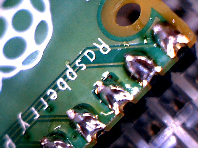
Brian Corteil took to Twitter to share his eleven-year-old’s pro soldering skills, proving that Raspberry Pi is for everyone, no matter how young, old, or inexperienced, or expert.
Extreme close-up!
Look at the finish on those pins!
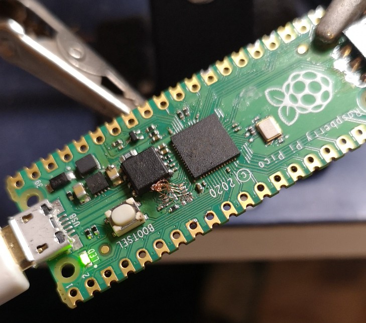
16MB Pico modification
Daniel Green did what you were all thinking – desoldered the onboard 2MB QSPI flash chip and replaced it with a 16MB version. Say hello to the first Pico in the world with this special modification.
Eben himself!
On top of all the brilliant comments, projects, and guidance our community has already shared, Raspberry Pi CEO Eben Upton will be joining the Digital Making at Home crew on Wednesday to show young coders around Raspberry Pi Pico.
In the extra special Raspberry Pi Pico launch issue of HackSpace magazine, editor Ben Everard shows you how to get extra levels of brightness out of your LEDs with our new board.
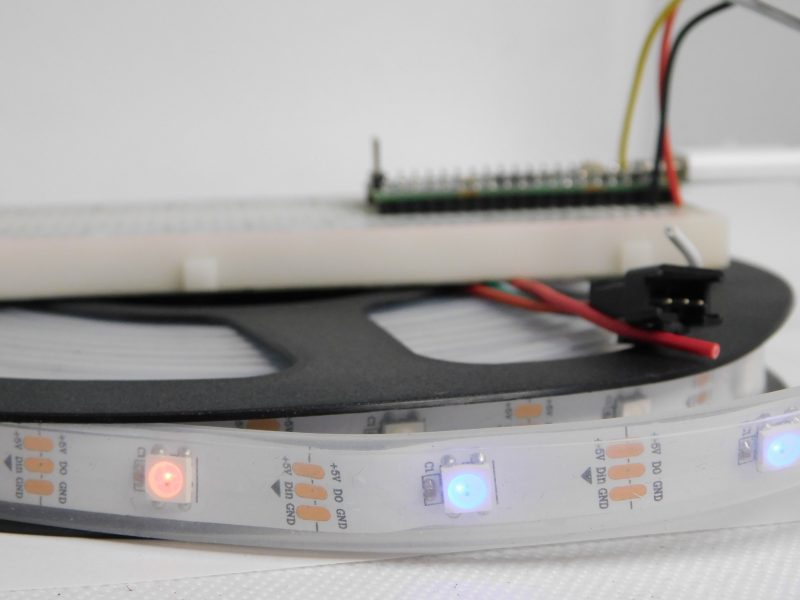
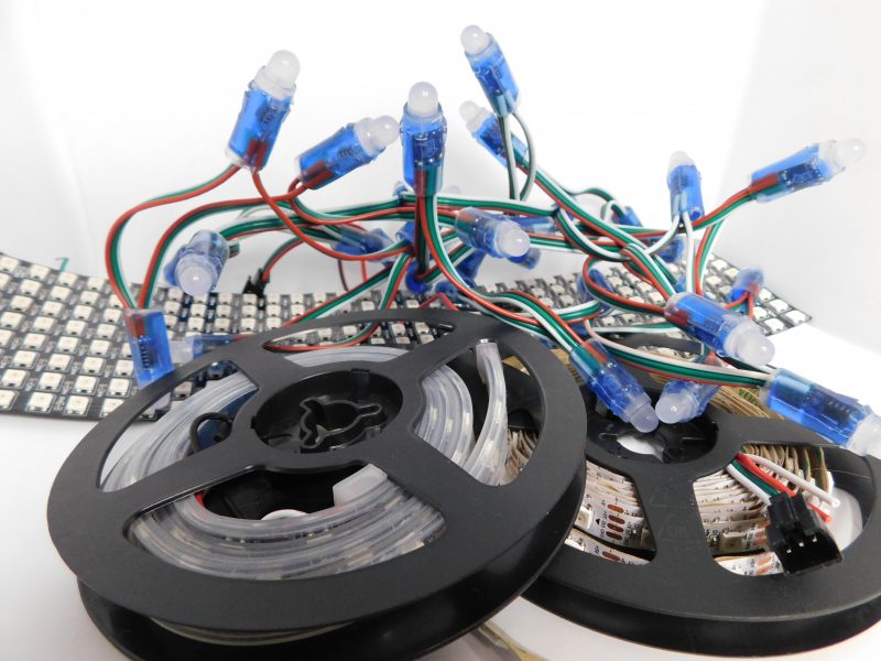
WS2812B LEDs, commonly known as NeoPixels, are cheap and widely available LEDs. They have red, green, and blue LEDs in a single package with a microcontroller that lets you control a whole string of them using just one pin on your microcontroller.
The three connections may be in a different order on your LED strip, so check the labels to make sure they’re connected correctly
However, they do have a couple of disadvantages:
1) The protocol needed to control them is timing-dependent and often has to be bit-banged.
2) Each colour has 8 bits, so has 255 levels of brightness. However, these aren’t gamma-corrected, so the low levels of brightness have large steps between them. For small projects, we often find ourselves only using the lower levels of brightness, so often only have 10 or 20 usable levels of brightness.
There will usually be wires already connected to your strip, but if you cut it, you’ll need to solder new wires on
We’re going to look at how two features of Pico help solve these problems. Firstly, Programmable I/O (PIO) lets us implement the control protocol on a state machine rather than the main processing cores. This means that we don’t have to dedicate any processor time to sending the data out. Secondly, having two cores means we can use one of the processing cores to dither the NeoPixels. This means shift them rapidly between different brightness levels to make pseudo-levels of brightness.
For example, if we wanted a brightness level halfway between levels 3 and 4, we’d flick the brightness back and forth between 3 and 4. If we can do this fast enough, our eyes blur this into a single brightness level and we don’t see the flicker. By varying the amount of time at levels 3 and 4, we can make many virtual levels of brightness. While one core is doing this, we still have a processing core completely free to manipulate the data we want to display.
First, we’ll need a PIO program to communicate with the WS2812B LEDs. The Pico development team have provided an example PIO program to work with – you can see the full details here, but we’ll cover the essentials here. The PIO code is:
.program ws2812
.side_set 1
.define public T1 2
.define public T2 5
.define public T3 3
bitloop:
 out x, 1 side 0 [T3 - 1]
 jmp !x do_zero side 1 [T1 - 1]
 do_one:
 jmp bitloop side 1 [T2 - 1]
 do_zero:
 nop side 0 [T2 - 1]
We looked at the PIO syntax in the main cover feature, but it’s basically an assembly language for the PIO state machine. The WS2812B protocol uses pulses at a rate of 800kHz, but the length of the pulse determines if a 1 or a 0 is being sent. This code uses jumps to move through the loop to set the timings depending on whether the bit (stored in the register x) is 0 or 1. The T1, T2, and T3 variables hold the timings, so are used to calculate the delays (with 1 taken off as the instruction itself takes one clock cycle). There’s also a section in the pio file that links the PIO code and the C code:
This line sets up the output shift register which holds each 32 bits of data before it’s moved bit by bit into the PIO state machine. The parameters are the config (that we’re setting up and will use to initialise the state machine); a Boolean value for shifting right or left (false being left); and a Boolean value for autopull which we have set to true. This means that whenever the output shift register falls below a certain threshold (set in the next parameter), the PIO will automatically pull in the next 32 bits of data.
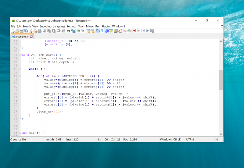
Using a text editor with programmer’s features such as syntax highlighting will make the job a lot easier
The final parameter is set using the expression rgbw ? 32 : 24. This means that if the variable rgbw is true, the value 32 is passed, otherwise 24 is passed. The rbgw variable is passed into this function when we create the PIO program from our C program and is used to specify whether we’re using an LED strip with four LEDs in each (using one red, one green, one blue, and one white) or three (red, green, and blue).
The PIO hardware works on 32-bit words, so each chunk of data we write with the values we want to send to the LEDs has to be 32 bits long. However, if we’re using RGB LED strips, we actually want to work in 24-bit lengths. By setting autopull to 24, we still pull in 32 bits each time, but once 24 bits have been read, another 32 bits are pulled in which overwrite the remaining 8 bits.
sm_config_set_fifo_join(&c, PIO_FIFO_JOIN_TX);
Each state machine has two four-word FIFOs attached to it. These can be used for one going in and one coming out. However, as we only have data going into our state machine, we can join them together to form a single eight-word FIFO using the above line. This gives us a small buffer of time to write data to in order to avoid the state machine running out of data and execution stalling. The following three lines are used to set the speed the state machine runs at:
int cycles_per_bit = ws2812_T1 + ws2812_T2 +
ws2812_T3;
 float div = clock_get_hz(clk_sys) / (freq *
cycles_per_bit);
 sm_config_clkdiv(&c, div);
The WS2812B protocol demands that data is sent out at a rate of 800kHz. However, each bit of data requires a number of state machine cycles. In this case, they’re defined in the variables T1, T2, and T3. If you look back at the original PIO program, you’ll see that these are used in the delays (always with 1 taken off the value because the initial instruction takes one cycle before the delay kicks in). Every loop of the PIO program will take T1 + T2 + T3 cycles. We use these values to calculate the speed we want the state machine to run at, and from there we can work out the divider we need to slow the system clock down to the right speed for the state machine. The final two lines just initialise and enable the state machine.
The main processor
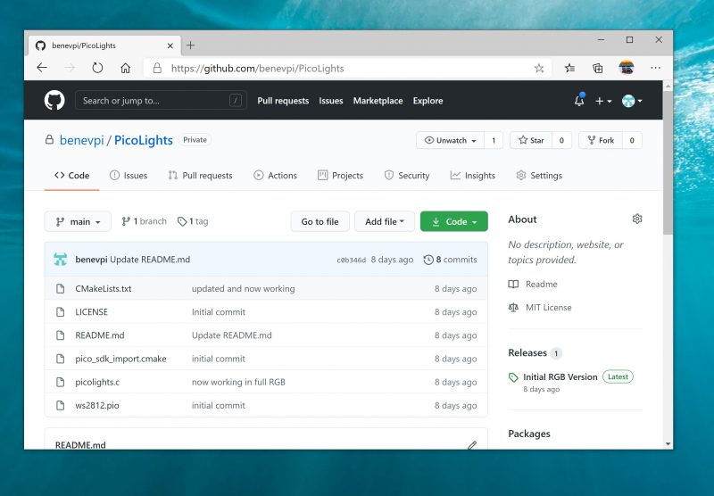
That’s the code that’s running on the state machine, so let’s now look at the code that’s running on our main processor cores. The full code is on github. Let’s first look at the code running on the second core (we’ll look at how to start this code running shortly), as this controls the light levels of the LEDs.
We start by defining a virtual bit depth. This is how many bits per pixel you can use. Our code will then attempt to create the necessary additional brightness levels. It will run as fast as it can drive the LED strip, but if you try to do too many brightness levels, you’ll start to notice flickering.
We found twelve to be about the best with strings up to around 100 LEDs, but you can experiment with others. Our code works with two arrays – pixels which holds the values that we want to display, and errors which holds the error in what we’ve displayed so far (there are three of each for the different colour channels).
If you just want to see this in action, you can download the UF2 file from hsmag.cc/orfgBD and flash it straight to your Pico
To explain that latter point, let’s take a look at the algorithm for determining how to light the LED. We borrowed this from the source code of Fadecandy by Micah Scott, but it’s a well-used algorithm for calculating error rates. We have an outer while loop that just keeps pushing out data to the LEDs as fast as possible. We don’t care about precise timings and just want as much speed as possible. We then go through each pixel.
The corresponding item in the errors array holds the cumulative amount our LED has been underlit so far compared to what we want it to be. Initially, this will be zero, but with each loop (if there’s a difference between what we want to light the LED and what we can light the LED) this error value will increase. These two numbers (the closest light level and the error) added together give the brightness at the pseudo-level, so we need to bit-shift this by the difference between our virtual level and the 8-bit brightness levels that are available.
This gives us the value for this pixel which we write out. We then need to calculate the new error level. Let’s take a look at what this means in practice. Suppose we want a brightness level halfway between 1 and 2 in the 8-bit levels. To simplify things, we’ll use nine virtual bits. 1 and 2 in 8-bit is 2 and 4 in 9 bits (adding an extra 0 to the end multiplies everything by a power of 2), so halfway between these two is a 9-bit value of 3 (or 11 in binary, which we’ll use from now on).
In the first iteration of our loop, pixels is 11, errors is 0, and shift is 1.
value = 11 >> 1 = 1
errors = 11 – 10 = 1
So this time, the brightness level of 1 is written out. The second iteration, we have:
value = 100 >> 1 = 10
errors = 100 – 100 = 0
So this time, the brightness level of 10 (in binary, or 2 in base 10) is written out. This time, the errors go back to 0, so we’re in the same position as at the start of the first loop. In this case, the LED will flick between the two brightness levels each loop so you’ll have a brightness half way between the two.
Using this simple algorithm, we can experiment with different virtual bit-depths. The algorithm will always handle the calculations for us, but we just have to see what creates the most pleasing visual effect for the eye. The larger the virtual bit depth, the more potential iterations you have to go through before the error accumulates enough to create a correction, so the more likely you are to see flicker. The biggest blocker to increasing the virtual bit depth is the sleep_us(400). This is needed to reset the LED strip.
NeoPixels come in many different shapes and sizes
Essentially, we throw out bits at 800kHz, and each block of 24 bits is sent, in turn, to the next LED. However, once there’s a long enough pause, everything resets and it goes back to the first LED. How big that pause is can vary. The truth is that a huge proportion of WS2812B LEDs are clones rather than official parts – and even for official parts, the length of the pause needed to reset has changed over the years.
400 microseconds is conservative and should work, but you may be able to get away with less (possibly even as low as 50 microseconds for some LEDs). The urgb_u32 method simply amalgamates the red, blue, and green values into a single 32-bit string (well, a 24-bit string that’s held inside a 32-bit string), and put_pixel sends this to the state machine. The bit shift there is to make sure the data is in the right place so the state machine reads the correct 24 bits from the output shift register.
Getting it running
We’ve now dealt with all the mechanics of the code. The only bit left is to stitch it all together.
int main() {
 PIO pio = pio0;
 int sm = 0;
 uint offset = pio_add_program(pio, &ws2812_
program);
 ws2812_program_init(pio, sm, offset, PIN_TX,
1000000, false);
 multicore_launch_core1(ws2812b_core);

 while (1) {
 for (int i = 0; i < 30; ++i) {
pixels[i] = i;

for (int j=0;j<30;++j){
 pixels[0] = j;
 if(j%8 == 0) { pixels[1] = j; }
 sleep_ms(50);
 }
 for (int j=30;j>0;--j){
 pixels[0] = j;
 if(j%8 == 0) { pixels[1] = j; }
 sleep_ms(50);
 }
 }
 } }
The method ws2812_program_init calls the method created in the PIO program to set everything up. To launch the algorithm creating the virtual bit-depth, we just have to use multicore_launch_core1 to set a function running on the other core. Once that’s done, whatever we put in the pixels array will be reflected as accurately as possible in the WS2812B LEDs. In this case, we simply fade it in and out, but you could do any animation you like.
Get a free Raspberry Pi Pico
Would you like a free Raspberry Pi Pico? Subscribe to HackSpace magazine via your preferred option here, and you’ll receive your new microcontroller in the mail before the next issue arrives.
To provide the best experiences, we use technologies like cookies to store and/or access device information. Consenting to these technologies will allow us to process data such as browsing behavior or unique IDs on this site. Not consenting or withdrawing consent, may adversely affect certain features and functions.
Functional
Always active
The technical storage or access is strictly necessary for the legitimate purpose of enabling the use of a specific service explicitly requested by the subscriber or user, or for the sole purpose of carrying out the transmission of a communication over an electronic communications network.
Preferences
The technical storage or access is necessary for the legitimate purpose of storing preferences that are not requested by the subscriber or user.
Statistics
The technical storage or access that is used exclusively for statistical purposes.The technical storage or access that is used exclusively for anonymous statistical purposes. Without a subpoena, voluntary compliance on the part of your Internet Service Provider, or additional records from a third party, information stored or retrieved for this purpose alone cannot usually be used to identify you.
Marketing
The technical storage or access is required to create user profiles to send advertising, or to track the user on a website or across several websites for similar marketing purposes.