You know we love a good cyberdeck around here, and we think you’ll love this video game emulator fresh from the latest issue of HackSpace magazine, out now.
We’ve only just finished printing a series on building a games cabinet using the RetroPie games emulator on a Raspberry Pi… and now something comes along that makes our plywood, full-size arcade machine look old hat.
This mostly 3D-printed cyberdeck features a 5-inch 800 × 480 touchscreen display, as well as the usual ports available through the Raspberry Pi 3 Model B+ that powers it. Quite how useful the screen’s portrait orientation will be for Sonic The Hedgehog is anyone’s guess, but if you’re playing any sort of top-down shooter, you’re laughing. The maker describes this project as a “video game emulator with some edge” – we think it’s pretty impressive for a project that began as an excuse to learn 3D design.
HackSpace magazine issue 47 out NOW!
Each month, HackSpace magazine brings you the best projects, tips, tricks and tutorials from the makersphere. You can get it from the Raspberry Pi Press online store or your local newsagents.
As always, every issue is free to download in PDF format from the HackSpace magazine website.
In the latest issue of HackSpace magazine, Ben Everard tests whether a bit of kit from Spotpear can turn Raspberry Pi Pico into a games machine.
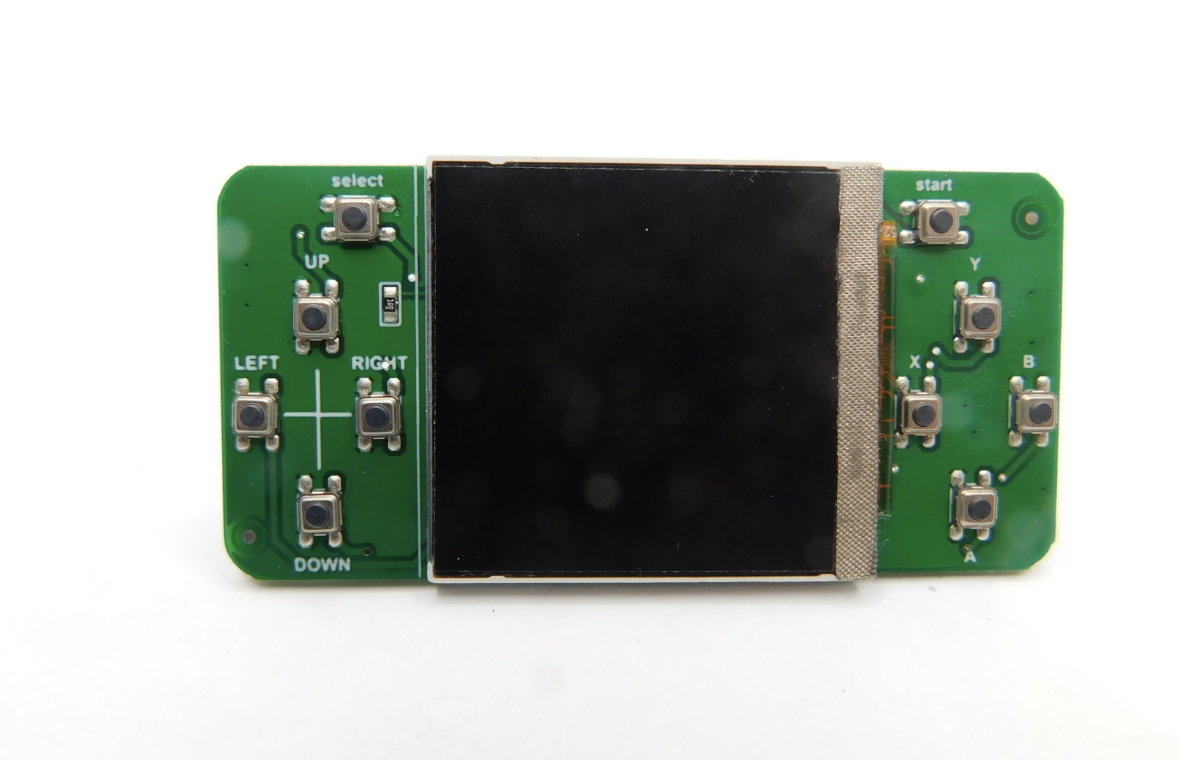
The snappily named Raspberry Pi Pico display 1.54-inch LCD by Spotpear ($11.89) brings in a 240×240 pixel IPS screen and ten buttons in a joypad-like arrangement. There’s four for direction, four for action, a select, and a start. At least, they’re labelled like this. You can use them for anything you like.
The buttons are just a bit too small and fiddly for us
To help you get started, there’s a short manual, which includes example code for MicroPython and C.
This example code is easy enough to use, but it is a little messy. The mechanism for controlling the hardware isn’t separated into its own module, so you’re left with either the task of building the library yourself or having slightly untidy code. Not the biggest inconvenience, but compared to how neatly some maker hardware companies manage their code, we found ourselves off to a disappointing start.
There are also some sample UF2 files included along with the C example code, but these appear to have been built for different hardware and work either partially or not at all. The actual example code did compile and work properly.
Impressive quality
When we ran the example code, we were impressed with the quality of the screen. With 240×240 pixels in just 1.54 inches, there’s a high pixel density that can give crisp graphics. Obviously, high pixel densities are a double-edged sword. While they can look great, it does mean higher RAM use, more time transferring data, and more data to process.
Fortunately, Pico is well-suited to the task of driving screens. Each pixel can take 16 bits of colour data, so a full-frame buffer is just 115,200 bytes. The display data is transferred by SPI, and Pico has a maximum SPI frequency of half the clock speed. For MicroPython, that means 62.5MHz. The actual data transfer rate is a little less than this because of overhead of the protocol, but we were able to drive full-frame refreshes at over 40 fps, which is plenty for smooth animations.
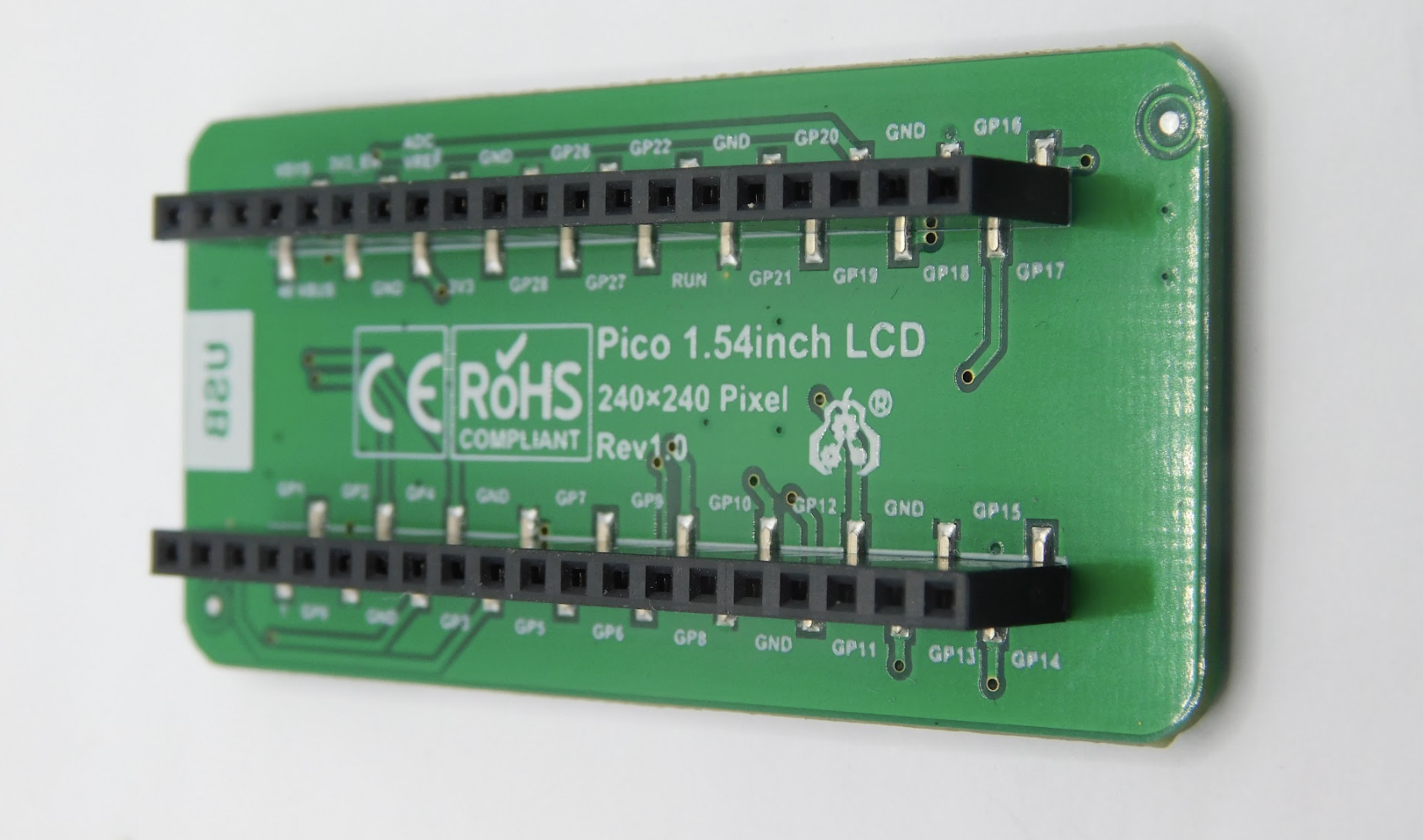
Pico slots in the back, which is perfect for space-constrained builds
Obviously, if you’re looking to do animations, sending the data is only half the story. You also need to calculate the frame before it’s displayed. If you’re using MicroPython, you are quite limited by the amount of processing you can do and still keep a high frame rate (though you could use the second core to offload some of the processing). With C, you’ve got much more scope, especially as you could potentially offload the data transfer using direct memory access (DMA).
Battery-sucking light
The one disappointing thing about the screen is that there’s no control over the backlight. According to the documentation, it should be attached to pin 13, but it isn’t. You can’t turn it on or off – it’s just permanently on, and quite bright. That’s a deal-breaker for anything running off battery power, as it will suck up a lot of power. However, if you want a display permanently on, this might be perfectly acceptable.
While we were quite impressed by the screen, we can’t say the same for the other part of the hardware – the buttons. They’re small, stiff, and have very little movement. The end result is a button that is hard to press, and hard to know if you’ve pressed it. They’re the sort of buttons that are commonly used as reset buttons as they’re hard to accidentally press.
We had hoped that this screen would make a good base for a games console, but unfortunately these buttons would just make for a frustrating experience. They might be OK for a menu-driven user interface, but that’s about it.
Another minor annoyance in this is the lack of any mounting holes. This makes it hard to embed into a project as the user interface.
We wanted to like this project. It’s got a good, high-res screen and a nice layout of buttons. However, the choice of components makes it hard to see how we’ll use this in our projects. We’re considering removing the surface-mount buttons and soldering wires onto them to make a more useful device, but if you’re going to go to that level of surgery, it’s probably better to start with a plain screen and work your way up from there.
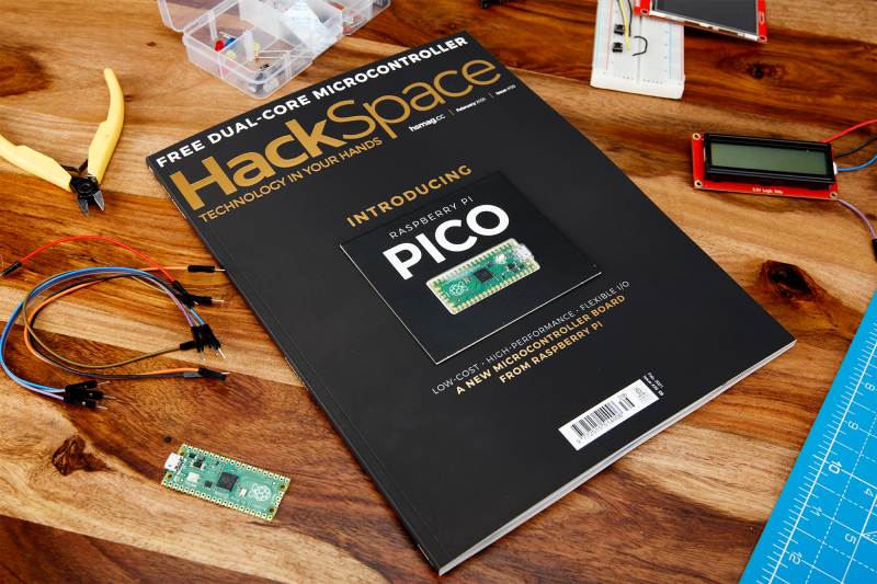
In the extra special Raspberry Pi Pico launch issue of HackSpace magazine, editor Ben Everard shows you how to get extra levels of brightness out of your LEDs with our new board.
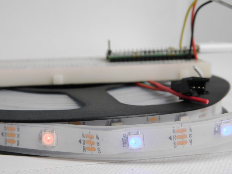
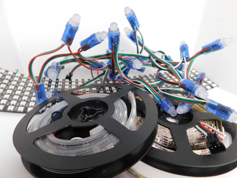
WS2812B LEDs, commonly known as NeoPixels, are cheap and widely available LEDs. They have red, green, and blue LEDs in a single package with a microcontroller that lets you control a whole string of them using just one pin on your microcontroller.
The three connections may be in a different order on your LED strip, so check the labels to make sure they’re connected correctly
However, they do have a couple of disadvantages:
1) The protocol needed to control them is timing-dependent and often has to be bit-banged.
2) Each colour has 8 bits, so has 255 levels of brightness. However, these aren’t gamma-corrected, so the low levels of brightness have large steps between them. For small projects, we often find ourselves only using the lower levels of brightness, so often only have 10 or 20 usable levels of brightness.
There will usually be wires already connected to your strip, but if you cut it, you’ll need to solder new wires on
We’re going to look at how two features of Pico help solve these problems. Firstly, Programmable I/O (PIO) lets us implement the control protocol on a state machine rather than the main processing cores. This means that we don’t have to dedicate any processor time to sending the data out. Secondly, having two cores means we can use one of the processing cores to dither the NeoPixels. This means shift them rapidly between different brightness levels to make pseudo-levels of brightness.
For example, if we wanted a brightness level halfway between levels 3 and 4, we’d flick the brightness back and forth between 3 and 4. If we can do this fast enough, our eyes blur this into a single brightness level and we don’t see the flicker. By varying the amount of time at levels 3 and 4, we can make many virtual levels of brightness. While one core is doing this, we still have a processing core completely free to manipulate the data we want to display.
First, we’ll need a PIO program to communicate with the WS2812B LEDs. The Pico development team have provided an example PIO program to work with – you can see the full details here, but we’ll cover the essentials here. The PIO code is:
.program ws2812
.side_set 1
.define public T1 2
.define public T2 5
.define public T3 3
bitloop:
out x, 1 side 0 [T3 - 1]
jmp !x do_zero side 1 [T1 - 1]
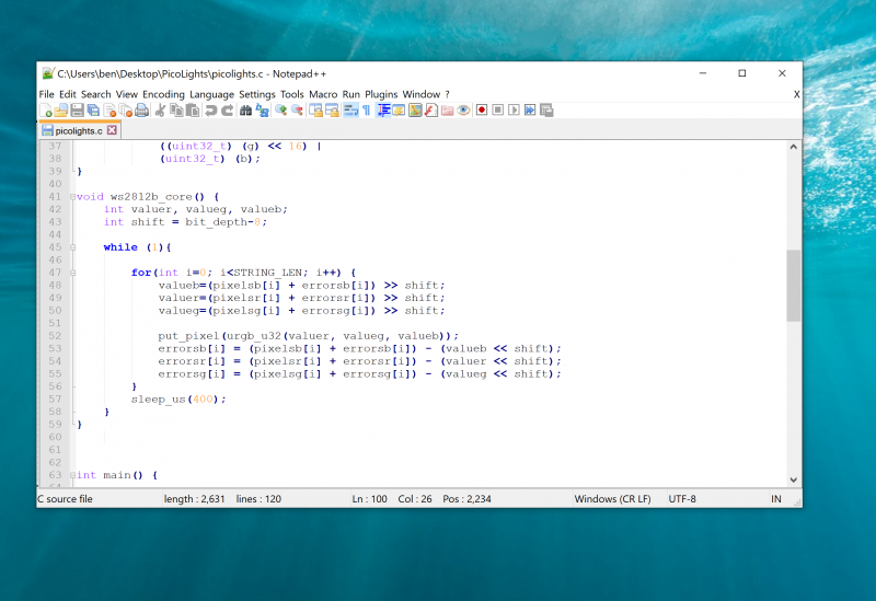
do_one:
jmp bitloop side 1 [T2 - 1]
do_zero:
nop side 0 [T2 - 1]
We looked at the PIO syntax in the main cover feature, but it’s basically an assembly language for the PIO state machine. The WS2812B protocol uses pulses at a rate of 800kHz, but the length of the pulse determines if a 1 or a 0 is being sent. This code uses jumps to move through the loop to set the timings depending on whether the bit (stored in the register x) is 0 or 1. The T1, T2, and T3 variables hold the timings, so are used to calculate the delays (with 1 taken off as the instruction itself takes one clock cycle). There’s also a section in the pio file that links the PIO code and the C code:
This line sets up the output shift register which holds each 32 bits of data before it’s moved bit by bit into the PIO state machine. The parameters are the config (that we’re setting up and will use to initialise the state machine); a Boolean value for shifting right or left (false being left); and a Boolean value for autopull which we have set to true. This means that whenever the output shift register falls below a certain threshold (set in the next parameter), the PIO will automatically pull in the next 32 bits of data.
Using a text editor with programmer’s features such as syntax highlighting will make the job a lot easier
The final parameter is set using the expression rgbw ? 32 : 24. This means that if the variable rgbw is true, the value 32 is passed, otherwise 24 is passed. The rbgw variable is passed into this function when we create the PIO program from our C program and is used to specify whether we’re using an LED strip with four LEDs in each (using one red, one green, one blue, and one white) or three (red, green, and blue).
The PIO hardware works on 32-bit words, so each chunk of data we write with the values we want to send to the LEDs has to be 32 bits long. However, if we’re using RGB LED strips, we actually want to work in 24-bit lengths. By setting autopull to 24, we still pull in 32 bits each time, but once 24 bits have been read, another 32 bits are pulled in which overwrite the remaining 8 bits.
sm_config_set_fifo_join(&c, PIO_FIFO_JOIN_TX);
Each state machine has two four-word FIFOs attached to it. These can be used for one going in and one coming out. However, as we only have data going into our state machine, we can join them together to form a single eight-word FIFO using the above line. This gives us a small buffer of time to write data to in order to avoid the state machine running out of data and execution stalling. The following three lines are used to set the speed the state machine runs at:
int cycles_per_bit = ws2812_T1 + ws2812_T2 +
ws2812_T3;
 float div = clock_get_hz(clk_sys) / (freq *
cycles_per_bit);
 sm_config_clkdiv(&c, div);
The WS2812B protocol demands that data is sent out at a rate of 800kHz. However, each bit of data requires a number of state machine cycles. In this case, they’re defined in the variables T1, T2, and T3. If you look back at the original PIO program, you’ll see that these are used in the delays (always with 1 taken off the value because the initial instruction takes one cycle before the delay kicks in). Every loop of the PIO program will take T1 + T2 + T3 cycles. We use these values to calculate the speed we want the state machine to run at, and from there we can work out the divider we need to slow the system clock down to the right speed for the state machine. The final two lines just initialise and enable the state machine.
The main processor
That’s the code that’s running on the state machine, so let’s now look at the code that’s running on our main processor cores. The full code is on github. Let’s first look at the code running on the second core (we’ll look at how to start this code running shortly), as this controls the light levels of the LEDs.
We start by defining a virtual bit depth. This is how many bits per pixel you can use. Our code will then attempt to create the necessary additional brightness levels. It will run as fast as it can drive the LED strip, but if you try to do too many brightness levels, you’ll start to notice flickering.
We found twelve to be about the best with strings up to around 100 LEDs, but you can experiment with others. Our code works with two arrays – pixels which holds the values that we want to display, and errors which holds the error in what we’ve displayed so far (there are three of each for the different colour channels).
If you just want to see this in action, you can download the UF2 file from hsmag.cc/orfgBD and flash it straight to your Pico
To explain that latter point, let’s take a look at the algorithm for determining how to light the LED. We borrowed this from the source code of Fadecandy by Micah Scott, but it’s a well-used algorithm for calculating error rates. We have an outer while loop that just keeps pushing out data to the LEDs as fast as possible. We don’t care about precise timings and just want as much speed as possible. We then go through each pixel.
The corresponding item in the errors array holds the cumulative amount our LED has been underlit so far compared to what we want it to be. Initially, this will be zero, but with each loop (if there’s a difference between what we want to light the LED and what we can light the LED) this error value will increase. These two numbers (the closest light level and the error) added together give the brightness at the pseudo-level, so we need to bit-shift this by the difference between our virtual level and the 8-bit brightness levels that are available.
This gives us the value for this pixel which we write out. We then need to calculate the new error level. Let’s take a look at what this means in practice. Suppose we want a brightness level halfway between 1 and 2 in the 8-bit levels. To simplify things, we’ll use nine virtual bits. 1 and 2 in 8-bit is 2 and 4 in 9 bits (adding an extra 0 to the end multiplies everything by a power of 2), so halfway between these two is a 9-bit value of 3 (or 11 in binary, which we’ll use from now on).
In the first iteration of our loop, pixels is 11, errors is 0, and shift is 1.
value = 11 >> 1 = 1
errors = 11 – 10 = 1
So this time, the brightness level of 1 is written out. The second iteration, we have:
value = 100 >> 1 = 10
errors = 100 – 100 = 0
So this time, the brightness level of 10 (in binary, or 2 in base 10) is written out. This time, the errors go back to 0, so we’re in the same position as at the start of the first loop. In this case, the LED will flick between the two brightness levels each loop so you’ll have a brightness half way between the two.
Using this simple algorithm, we can experiment with different virtual bit-depths. The algorithm will always handle the calculations for us, but we just have to see what creates the most pleasing visual effect for the eye. The larger the virtual bit depth, the more potential iterations you have to go through before the error accumulates enough to create a correction, so the more likely you are to see flicker. The biggest blocker to increasing the virtual bit depth is the sleep_us(400). This is needed to reset the LED strip.
NeoPixels come in many different shapes and sizes
Essentially, we throw out bits at 800kHz, and each block of 24 bits is sent, in turn, to the next LED. However, once there’s a long enough pause, everything resets and it goes back to the first LED. How big that pause is can vary. The truth is that a huge proportion of WS2812B LEDs are clones rather than official parts – and even for official parts, the length of the pause needed to reset has changed over the years.
400 microseconds is conservative and should work, but you may be able to get away with less (possibly even as low as 50 microseconds for some LEDs). The urgb_u32 method simply amalgamates the red, blue, and green values into a single 32-bit string (well, a 24-bit string that’s held inside a 32-bit string), and put_pixel sends this to the state machine. The bit shift there is to make sure the data is in the right place so the state machine reads the correct 24 bits from the output shift register.
Getting it running
We’ve now dealt with all the mechanics of the code. The only bit left is to stitch it all together.
int main() {
 PIO pio = pio0;
 int sm = 0;
 uint offset = pio_add_program(pio, &ws2812_
program);
 ws2812_program_init(pio, sm, offset, PIN_TX,
1000000, false);
 multicore_launch_core1(ws2812b_core);

 while (1) {
 for (int i = 0; i < 30; ++i) {
pixels[i] = i;

for (int j=0;j<30;++j){
 pixels[0] = j;
 if(j%8 == 0) { pixels[1] = j; }
 sleep_ms(50);
 }
 for (int j=30;j>0;--j){
 pixels[0] = j;
 if(j%8 == 0) { pixels[1] = j; }
 sleep_ms(50);
 }
 }
 } }
The method ws2812_program_init calls the method created in the PIO program to set everything up. To launch the algorithm creating the virtual bit-depth, we just have to use multicore_launch_core1 to set a function running on the other core. Once that’s done, whatever we put in the pixels array will be reflected as accurately as possible in the WS2812B LEDs. In this case, we simply fade it in and out, but you could do any animation you like.
Get a free Raspberry Pi Pico
Would you like a free Raspberry Pi Pico? Subscribe to HackSpace magazine via your preferred option here, and you’ll receive your new microcontroller in the mail before the next issue arrives.
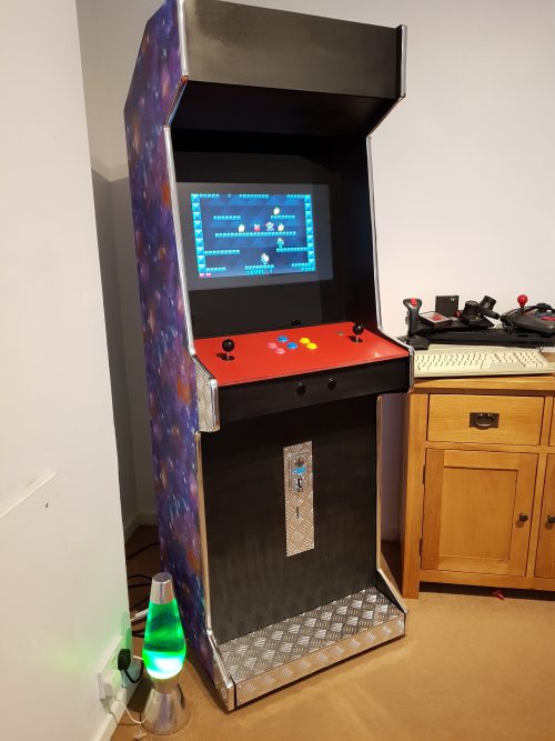
Games consoles might be fast and have great graphics, but they’re no match for the entertainment value of a proper arcade machine. In this month’s issue of Hackspace magazine, you’re invited to relive your misspent youth with this huge build project.
There’s something special about the comforting solidity of a coin-eating video game monolith, and nothing screams retro fun like a full-sized arcade cabinet sitting in the corner of the room. Classic arcade machines can be a serious investment. Costing thousands of pounds and weighing about the same as a giant panda, they’re out of reach for all but the serious collector. Thankfully, you can recreate that retro experience using modern components for a fraction of the price and weight.
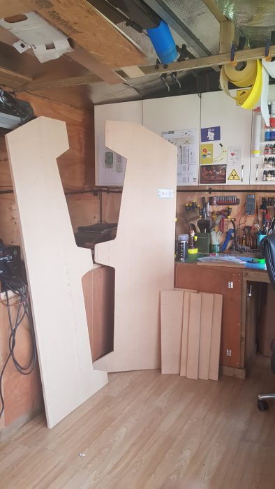
An arcade cabinet is much easier to make than you might expect. It’s essentially a fancy cupboard that holds a monitor, speakers, a computer, a keyboard, and some buttons. You can make your own cabinet using not much more than a couple of sheets of MDF, some clear plastic, and a few cans of spray paint.
If you want a really authentic-looking cabinet, you can find plenty of plans and patterns online. However, most classic cabinets are a bit bigger than you might remember, occupying almost a square metre of floor space. If you scale that down to approximately 60 cm2, you can make an authentic-looking home arcade cabinet that won’t take over the entire room, and can be cut from just two pieces of 8 × 4 (2440 mm × 1220 mm) MDF. You can download our plans, but these are rough plans designed for you to tweak into your own creation. A sheet of 18 mm MDF is ideal for making the body of the cabinet, and 12 mm MDF works well to fill in the front and back panels. You can use thinner sheets of wood to make a lighter cabinet, but you might find it less sturdy and more difficult to screw into.
See – simples
The sides of the machine should be cut from 18 mm MDF, and will be 6 feet high. The sides need to be as close to identical as possible, so mark out the pattern for the side on one piece of 18 mm MDF, and screw the boards together to hold them while you cut. You can avoid marking the sides by placing the screws through the waste areas of the MDF. Keep these offcuts to make internal supports or brackets. You can cut the rest of the pieces of MDF using the project plans as a guide.
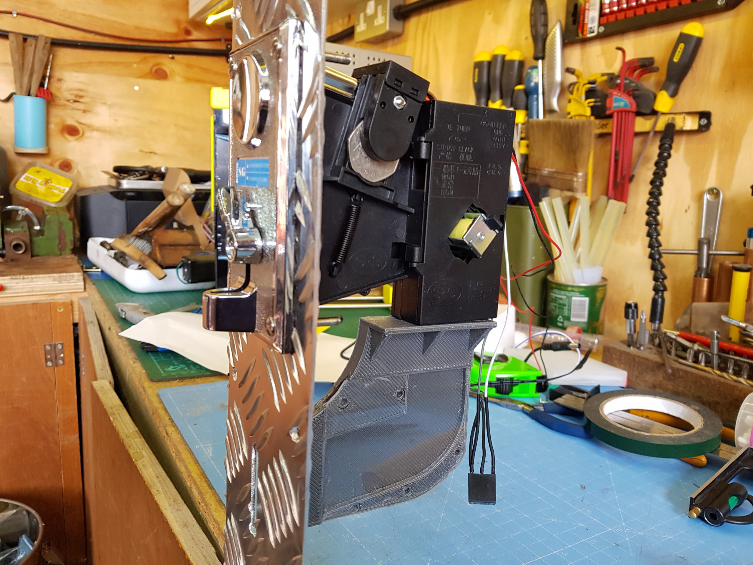
Why not add a coin machine for extra authenticity
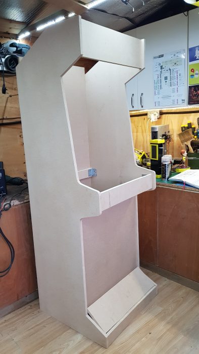
Attach the side pieces to the base, so that the sides hang lower than the base by an inch or two. If you’re more accomplished at woodworking and want to make the strongest cabinet possible, you can use a router to joint and glue the pieces of wood together. This will make the cabinet very slightly narrower and will affect some measurements, but if you follow the old adage to measure twice and cut once, you should be fine. If you don’t want to do this, you can use large angle brackets and screws to hold everything together. The cabinet will still be strong, and you’ll have the added advantage that you can disassemble it in the future if necessary.
Keep attaching the 18 mm MDF pieces, starting with the top piece and the rear brace. Once you have these pieces attached, the cabinet should be sturdy enough to start adding the thinner panels. Insetting the panels by about an inch gives the cabinet that retro look, and also hides any design crimes you might have committed while cutting out the side panels.
The absolute sizing of the cabinet isn’t critical unless you’re trying to make an exact copy of an old machine, so don’t feel too constrained by measuring things down to the millimetre. As long as the cabinet is wide enough to accept your monitor, everything else is moveable and can be adjusted to suit your needs.
Make it shiny
You can move onto decoration once the cabinet woodwork is fitted together. This is mostly down to personal preference, although it’s wise to think about which parts of the case will be touched more often, and whether your colour choices will cause any problems with screen reflection. Matt black is a popular choice for arcade cabinets because it’s non-reflective and any surface imperfections are less noticeable with a matt paint finish.
Aluminium checker plate is a good way of protecting your cabinet from damage, and it can be cut and shaped easily.
Wallpaper or posters make a great choice for decorating the outside of the cabinet, and they are quick to apply. Just be sure to paste all the way up to the edge, and protect any areas that will be handled regularly with aluminium checker plate or plastic sheet. The edges of MDF sheets can be finished with iron-on worktop edging, or with the chrome detailing tape used on cars. You can buy detailing tape in 12 mm and 18 mm widths, which makes it great for finishing edges. The adhesive tape provided with the chrome edging isn’t always very good, so it’s worth investing in some high-strength, double-sided clear vinyl foam tape.
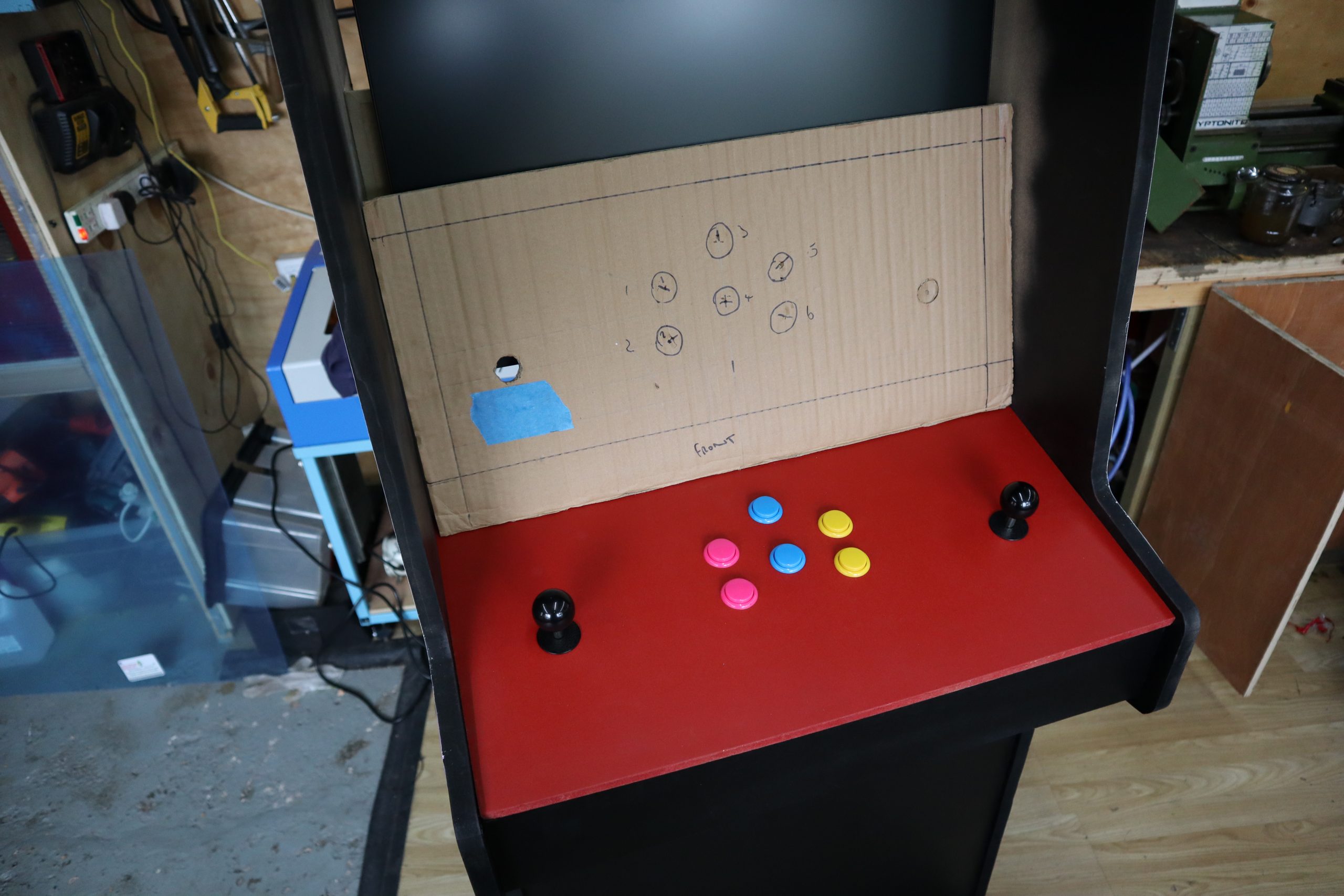
You’ve made your cabinet, but it’s empty at the moment. You’re going to add a Raspberry Pi, monitor, speakers, and a panel for buttons and joysticks. To find out how, you can read the full article in HackSpace magazine 35.
Get HackSpace magazine 35 Out Now!
Each month, HackSpace magazine brings you the best projects, tips, tricks and tutorials from the makersphere. You can get it from the Raspberry Pi Press online store, The Raspberry Pi store in Cambridge, or your local newsagents.
If you subscribe for 12 months, you get an Adafruit Circuit Playground Express , or can choose from one of our other subscription offers, including this amazing limited-time offer of three issues and a book for only £10!
To provide the best experiences, we use technologies like cookies to store and/or access device information. Consenting to these technologies will allow us to process data such as browsing behavior or unique IDs on this site. Not consenting or withdrawing consent, may adversely affect certain features and functions.
Functional
Always active
The technical storage or access is strictly necessary for the legitimate purpose of enabling the use of a specific service explicitly requested by the subscriber or user, or for the sole purpose of carrying out the transmission of a communication over an electronic communications network.
Preferences
The technical storage or access is necessary for the legitimate purpose of storing preferences that are not requested by the subscriber or user.
Statistics
The technical storage or access that is used exclusively for statistical purposes.The technical storage or access that is used exclusively for anonymous statistical purposes. Without a subpoena, voluntary compliance on the part of your Internet Service Provider, or additional records from a third party, information stored or retrieved for this purpose alone cannot usually be used to identify you.
Marketing
The technical storage or access is required to create user profiles to send advertising, or to track the user on a website or across several websites for similar marketing purposes.