Post Syndicated from Sheila Busser original https://aws.amazon.com/blogs/compute/building-a-cloud-in-the-cloud-running-apache-cloudstack-on-amazon-ec2-part-2/
This blog is written by Mark Rogers, SDE II – Customer Engineering AWS.
In part 1, I showed you how to run Apache CloudStack with KVM on a single Amazon Elastic Compute Cloud (Amazon EC2) instance. That simple setup is great for experimentation and light workloads. In this post, things will get a lot more interesting. I’ll show you how to create an overlay network in your Amazon Virtual Private Cloud (Amazon VPC) that allows CloudStack to scale horizontally across multiple EC2 instances. This same method could work with other hypervisors, too.
If you haven’t read it yet, then start with part 1. It explains why this network setup is necessary. The same prerequisites apply to both posts.
Making things easier
I wrote some scripts to automate the CloudStack installation and OS configuration on CentOS 7. You can customize them to meet your needs. I also wrote some AWS CloudFormation templates you can copy in order to create a demo environment. The README file has more details.
The scalable method
Our team started out using a single EC2 instance, as described in my last post. That worked at first, but it didn’t have the capacity we needed. We were limited to a couple of dozen VMs, but we needed hundreds. We also needed to scale up and down as our needs changed. This meant we needed the ability to add and remove CloudStack hosts. Using a Linux bridge as a virtual subnet was no longer adequate.
To support adding hosts, we need a subnet that spans multiple instances. The solution I found is Virtual Extensible LAN (VXLAN). It’s lightweight, easy to configure, and included in the Linux kernel. VXLAN creates a layer 2 overlay network that abstracts away the details of the underlying network. It allows machines in different parts of a network to communicate as if they’re all attached to the same simple network switch.
Another example of an overlay network is an Amazon VPC. It acts like a physical network, but it’s actually a layer on top of other networks. It’s networks all the way down. VXLAN provides a top layer where CloudStack can sit comfortably, handling all of your VM needs, blissfully unaware of the world below it.
An overlay network comes with some big advantages. The biggest improvement is that you can have multiple hosts, allowing for horizontal scaling. Having more hosts not only gives you more computing power, but also lets you do rolling maintenance. Instead of putting the database and file storage on the management server, I’ll show you how to use Amazon Elastic File System (Amazon EFS) and Amazon Relational Database Service (Amazon RDS) for scalable and reliable storage.
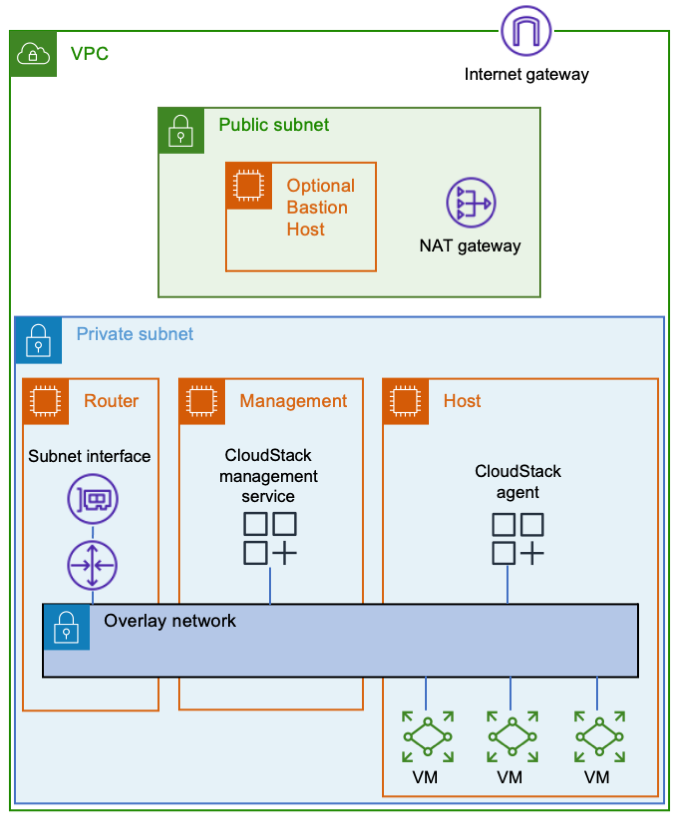
EC2 Instances
Let’s start with three Amazon EC2 instances. One will be a router between the overlay network and your Amazon VPC, the second one will be your CloudStack management server, and the third one will be your VM host. You’ll also need a way to connect to your instances, such as a bastion host or a VPN endpoint.
 VXLAN must send and receive multicast traffic. Only Nitro instances can be multicast senders. As you plan, look at the list of Nitro instance types.
The router won’t need much computing power, but it will need enough network bandwidth to meet your needs. If you put Amazon EFS in the same subnet as your instances, then they’ll communicate with it directly, thereby reducing the load on the router. Decide how much network throughput you want, and then pick a suitable Nitro instance type.
After creating the router instance, configure AWS to use it as a router. Stop source/destination checking in the instance’s network settings. Then update the applicable AWS route tables to use the router as the target for the overlay network. The router’s security group needs to allow ingress to the CloudStack UI (TCP port 8080) and any services you plan to offer from VMs.
For the management server, you’ll want a Nitro instance type. It’s going to use more CPU than your router, so plan accordingly.
In addition to being a Nitro type, the host instance must also be a metal type. Metal instances have hardware virtualization support, which is needed by KVM. If you have a new AWS account with a low on-demand vCPU limit, then consider starting with an m5zn.metal, which has 48 vCPUs. Otherwise, I suggest going directly to a c5.metal because it provides 96 vCPUs for a similar price. There are bigger types available depending on your compute needs, budget, and vCPU limit. If your account’s on-demand vCPU limit is too low, then you can file a support ticket to have it raised.
Networking
All of the instances should be on a dedicated subnet. Sharing the subnet with other instances can cause communication issues. For an example, refer to the following figure. The subnet has an instance named TroubleMaker that’s not on the overlay network. If TroubleMaker sends a request to the management instance’s overlay network address, then here’s what happens:
- The request goes through the AWS subnet to the router.
- The router forwards the request via the overlay network.
- The CloudStack management instance has a connection to the same AWS subnet that TroubleMaker is on. Therefore, it responds directly instead of using the router. This isn’t the return path that AWS is expecting, so the response is dropped.

If you move TroubleMaker to a different subnet, then the requests and responses will all go through the router. That will fix the communication issues.
The instances in the overlay network will use special interfaces that serve as VXLAN tunnel endpoints (VTEPs). The VTEPs must know how to contact each other via the underlay network. You could manually give each instance a list of all of the other instances, but that’s a maintenance nightmare. It’s better to let the VTEPs discover each other, which they can do using multicast. You can add multicast support using AWS Transit Gateway.
Here are the steps to make VXLAN multicasts work:
- Enable multicast support when you create the transit gateway.
- Attach the transit gateway to your subnet.
- Create a transit gateway multicast domain with IGMPv2 support enabled.
- Associate the multicast domain with your subnet.
- Configure the eth0 interface on each instance to use IGMPv2. The following sample code shows how to do this.
- Make sure that your instance security groups allow ingress for IGMP queries (protocol 2 traffic from 0.0.0.0/32) and VXLAN traffic (UDP port 4789 from the other instances).
CloudStack VMs must connect to the same bridge as the VXLAN interface. As mentioned in the previous post, CloudStack cares about names. I recommend giving the interface a name starting with “eth”. Moreover, this naming convention tells CloudStack which bridge to use, thereby avoiding the need for a dummy interface like the one in the simple setup.
The following snippet shows how I configured the networking in CentOS 7. You must provide values for these variables:
$overlay_host_ip_address,$overlay_netmask, and$overlay_gateway_ip: Use values for the overlay network that you’re creating.$dns_address: I recommend using the base of the VPC IPv4 network range, plus two. You shouldn’t use 169.654.169.253 because CloudStack reserves link-local addresses for its own use.$multicast_address: The multicast address that you want VXLAN to use. Pick something in the multicast range that won’t conflict with anything else. I recommend choosing from the IPv4 local scope (239.255.0.0/16).$interface_name: The name of the interface VXLAN should use to communicate with the physical network. This is typically eth0.
A couple of the steps are different for the router instance than for the other instances. Pay attention to the comments!
yum install -y bridge-utils net-tools

# IMPORTANT: Omit the GATEWAY setting on the router instance!
cat << EOF > /etc/sysconfig/network-scripts/ifcfg-cloudbr0
DEVICE=cloudbr0
TYPE=Bridge
ONBOOT=yes
BOOTPROTO=none
IPV6INIT=no
IPV6_AUTOCONF=no
DELAY=5
STP=no
USERCTL=no
NM_CONTROLLED=no
IPADDR=$overlay_host_ip_address
NETMASK=$overlay_netmask
DNS1=$dns_address
GATEWAY=$overlay_gateway_ip
EOF

cat << EOF > /sbin/ifup-local
#!/bin/bash
# Set up VXLAN once cloudbr0 is available.
if [[ \$1 == "cloudbr0" ]]
then
    ip link add ethvxlan0 type vxlan id 100 dstport 4789 group "$multicast_address" dev "$interface_name"
    brctl addif cloudbr0 ethvxlan0
    ip link set up dev ethvxlan0
fi
EOF

chmod +x /sbin/ifup-local

# Transit Gateway requires IGMP version 2
echo "net.ipv4.conf.$interface_name.force_igmp_version=2" >> /etc/sysctl.conf
sysctl -p

# Enable IPv4 forwarding
# IMPORTANT: Only do this on the router instance!
echo 'net.ipv4.ip_forward=1' >> /etc/sysctl.conf
sysctl -p

# Restart the network service to make the changes take effect.
systemctl restart network
Storage
Let’s look at storage. Create an Amazon RDS database using the MySQL 8.0 engine, and set a master password for CloudStack’s database setup tool to use. Refer to the CloudStack documentation to find the MySQL settings that you’ll need. You can put the settings in an RDS parameter group. In case you’re wondering why I’m not using Amazon Aurora, it’s because CloudStack needs the MyISAM storage engine, which isn’t available in Aurora.
I recommend Amazon EFS for file storage. For efficiency, create a mount target in the subnet with your EC2 instances. That will enable them to communicate directly with the mount target, thereby bypassing the overlay network and router. Note that the system VMs will use Amazon EFS via the router.
If you want, you can consolidate your CloudStack file systems. Just create a single file system with directories for each zone and type of storage. For example, I use directories named /zone1/primary, /zone1/secondary, /zone2/primary, etc. You should also consider enabling provisioned throughput on the file system, or you may run out of bursting credits after booting a few VMs.
One consequence of the file system’s scalability is that the amount of free space (8 exabytes) will cause an integer overflow in CloudStack! To avoid this problem, reduce storage.overprovisioning.factor in CloudStack’s global settings from 2 to 1.
When your environment is ready, install CloudStack. When it asks for a default gateway, remember to use the router’s overlay network address. When you add a host, make sure that you use the host’s overlay network IP address.
Cleanup
If you used my CloudFormation template, delete the stack and remove any route table entries you added.
If you didn’t use CloudFormation, here are the things to delete:
- The CloudStack EC2 instances
- The Amazon RDS database and parameter group
- The Amazon EFS file system
- The transit gateway multicast domain subnet association
- The transit gateway multicast domain
- The transit gateway VPC attachment
- The transit gateway
- The route table entries that you created
- The security groups that you created for the instances, database, and file system
Conclusion
The approach I shared has many steps, but they’re not bad when you have a plan. Whether you need a simple setup for experiments, or you need a scalable environment for a data center migration, you now have a path forward. Give it a try, and comment here about the things you learned. I hope you find it useful and fun!
“Apache”, “Apache CloudStack”, and “CloudStack” are trademarks of the Apache Software Foundation.