All posts by Alasdair Allan

Bring on the documentation

Post Syndicated from Alasdair Allan original https://www.raspberrypi.org/blog/bring-on-the-documentation/

I joined Raspberry Pi eighteen months ago and spent my first year here keeping secrets and writing about Raspberry Silicon, and the chip that would eventually be known as RP2040. This is all (largely) completed work: Raspberry Pi Pico made its way out into the world back in January, and our own Raspberry Silicon followed last month.

The question is then, what have I done for you lately?

The Documentation

Until today our documentation for the “big” boards — as opposed to Raspberry Pi Pico — lived in a Github repository and was written in Github-flavoured Markdown. From there our documentation site was built from the Markdown source, which was pulled periodically from the repository, run through a script written many years ago which turned it into HTML, and then deployed onto our website.

This all worked really rather well in the early days of Raspberry Pi.

The old-style documentation

The documentation repository itself has been left to grow organically. When I arrived here, it needed to be restructured, and a great deal of non-Raspberry Pi specific documentation needed to be removed, while other areas were underserved and needed to be expanded. The documentation was created when there was a lot less third-party content around to support the Raspberry Pi, so a fair bit of it really isn’t that relevant anymore, and is better dealt with elsewhere on the web. And the structure was a spider’s web that, in places, made very little sense.

Frankly, it was all in a bit of a mess.

Enter the same team of folks that built the excellent PDF-based documentation for Raspberry Pi Pico and RP2040. The PDF documentation was built off an Asciidoc-based toolchain, and we knew from the outset that we’d want to migrate the Markdown-based documentation to Asciidoc. It’d offer us more powerful tools going forwards, and a lot more flexibility.

After working through the backlog of community pull requests, we took a snapshot of the current Markdown-based repository and built out a toolchain. A lot of which we intended to, and did, throw away after converting the Markdown to Asciidoc as our “source of truth.” This didn’t happen without a bit of a wrench; nobody throws working code away lightly. But it did mean we’d reached the point of no return.

The next generation of documentation

The result of our new documentation project launches today.

The new-look documentation

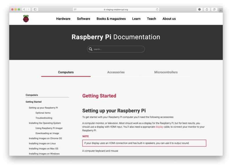
The new documentation site is built and deployed directly from the documentation repository using Github Actions when someone pushes to the master branch. However we’ll mostly be working on the develop branch in the repository, which is the default branch you’ll now get when you take a fresh checkout, and also the branch you should target for your pull requests.

We’ve always taken pull requests against the Markdown-based source behind our documentation site. Over the years as the documentation set has grown there have been hundreds of community contributors, who have made over 1,200 individual pull requests, ranging from fixing small typos, to contributing whole new sections.

With the introduction of the new site, we’re going to continue to take pull requests against the new Asciidoc-based documentation. However, we’re going to be a bit more targeted around what we’ll to accept into the documentation, and will be looking to keep the repository focussed on Raspberry Pi-specific things, rather than having generic Linux tutorial content.

The documentation itself will remain under a Creative Commons Attribution-Sharealike (CC BY-SA 4.0) license.

Product Information Portal

Supporting our customers in the best way we can when they build products around Raspberry Pi computers is important to us. A big part of this is being able to get customers access to the right documents easily. So alongside the new-look documentation, we have revamped how our customers (that’s you) get access to the documents you need for commercial applications of Raspberry Pi.

The Product Information Portal, or PIP as we’ve come to refer to it here at Pi Towers, is where documents such as regulatory paperwork, product change notices, and white papers will be stored and accessed from now on.

The new Product Information Portal (PIP)

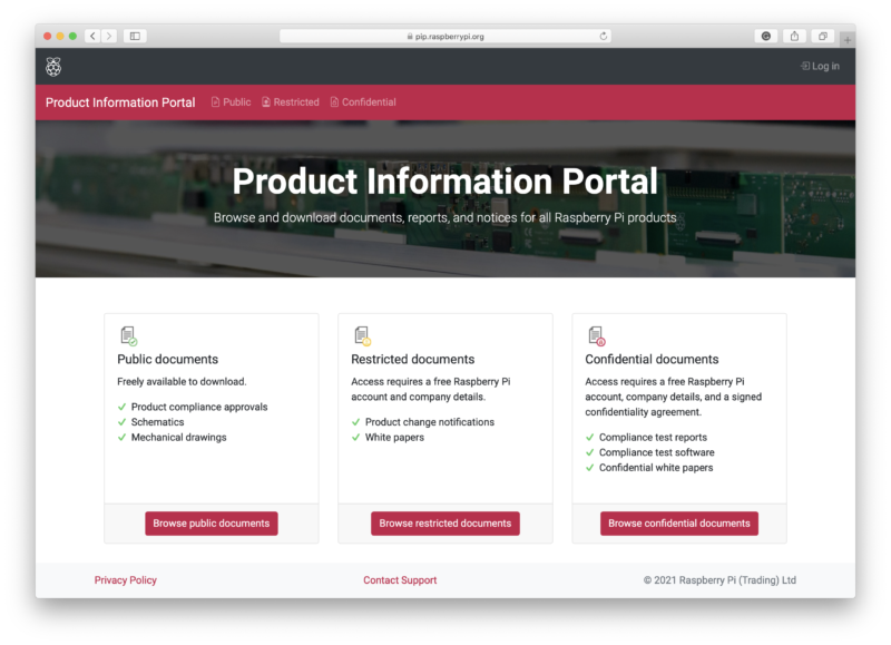
PIP has three tiers of document type: those which are publicly available; restricted documents that require a customer to sign up for a free account; and confidential documents which require a customer’s company to enter into a confidentiality agreement with Raspberry Pi.

PIP will also be a way for customers to get updates on products, allowing customers with a user account to subscribe to products, and receive email updates should there be a product change, regulatory update, or white paper release.

The portal can be found at pip.raspberrypi.org and will be constantly updated as new documents become available.

Where next?

I’m hoping that everyone that has contributed to the documentation over the years will see the new site as a big step towards making our documentation more accessible – and, as ever, we accept pull requests. However, if you’re already a contributor, the easiest thing to do is to take a fresh checkout of the repository, because things have changed a lot today.

Big changes to the look-and-feel of the documentation site

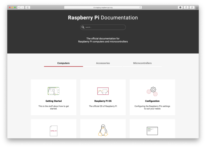
This isn’t the end. Instead, it’s the beginning of a journey to try and pull together our documentation into something that feels a bit more cohesive. While the documentation set now looks, and feels, a lot better and is (I think) a lot easier to navigate if you don’t know it well, there is still a lot of pruning and re-writing ahead of me. But we’ve reached the stage where I’m happy, and want to, work on that in public so the community can see how things are changing and can help out.

The post Bring on the documentation appeared first on Raspberry Pi.

How to get started with FUZIX on Raspberry Pi Pico

Post Syndicated from Alasdair Allan original https://www.raspberrypi.org/blog/how-to-get-started-with-fuzix-on-raspberry-pi-pico/

FUZIX is an old-school Unix clone that was initially written for the 8-bit Zilog Z80 processor and released by Alan Cox in 2014. At one time one of the most active Linux developers, Cox stepped back from kernel development in 2013. While the initial announcement has been lost in the mists because he made it on the now defunct Google+, Cox jokingly recommended the system for those longing for the good old days when all the source code still fitted on a single floppy disk.

FUZIX running on Raspberry Pi Pico
FUZIX running on Raspberry Pi Pico.

Since then FUZIX has been ported to other architectures such as 6502, 68000, and the MSP430. Earlier in the week David Given — who wrote both the MSP430 and ESP8266 ports — went ahead and ported it to Raspberry Pi Pico and RP2040.

So you can now run Unix on a $4 microcontroller.

Building FUZIX from source

FUZIX is a “proper” Unix with a serial console on Pico’s UART0 and SD card support, using the card both for the filesystem and for swap space. While there is a binary image available, it’s easy enough to build from source.

If you don’t already have the Raspberry Pi Pico toolchain set up and working you should go ahead and set up the C/C++ SDK.

Afterwards you need grab the the Pico port from GitHub.

$ git clone https://github.com/davidgiven/FUZIX.git
$ cd FUZIX
$ git checkout rpipico

Then change directory to the platform port

$ cd Kernel/platform-rpipico/

and edit the first line of the Makefile to set the path to your pico-sdk.

So for instance if you’re building things on a Raspberry Pi and you’ve run the pico_setup.sh script, or followed the instructions in our Getting Started guide, you’d point the PICO_SDK_PATH to

export PICO_SDK_PATH = /home/pi/pico/pico-sdk

After that you can go ahead and build both the FUZIX UF2 file and the root filesystem.

$ make world -j
$ ./update-flash.sh

If everything goes well you should have a UF2 file in build/fuzix.uf2 and a filesystem.img image file in your current working directory.

You can now load the UF2 file onto your Pico in the normal way.

Go grab your Raspberry Pi Pico board and a micro USB cable. Plug the cable into your Raspberry Pi or laptop, then press and hold the BOOTSEL button on your Pico while you plug the other end of the micro USB cable into the board. Then release the button after the board is plugged in.

A disk volume called RPI-RP2 should pop up on your desktop. Double-click to open it, and then drag and drop the UF2 file into it.

The volume will automatically unmount, and your Pico is now running Unix. Unfortunately it won’t be much use without a filesystem.

Building a bootable SD card

The filesystem.img image file we built earlier isn’t a bootable image. Unlike the Raspberry Pi OS images you might be used to, you can’t just use something like Raspberry Pi Imager to write it to an SD card. We’re going to have to get our hands a bit dirtier than that.

The following instructions are for building your file system on a Raspberry Pi, or another similar Linux platform. Comparable tools are available on both MS Windows and Apple macOS, but the exact details will differ.

Go grab a microSD card. As the partitions we’re going to put onto it are only going to take up 34MB it doesn’t really matter what size you’ve got to hand. I was using a 4GB card, as that was the smallest I could find, but it’s not that important.

Now plug the card into a USB card reader and then into your Raspberry Pi or laptop computer. We’re going to have to build the partition table that FUZIX is expecting, which consists of two partitions: the first a 2MB swap partition, and the second a 32MB root partition into which we can copy the root filesystem, our filesystem.img file.

Raspberry Pi 4 with USB card reader
Raspberry Pi 4 with USB card reader.

After plugging your card into the reader you can find it from the command line using the lsblk command. If you’ve have a blank unformatted card it will be visible as /dev/sda.

$ lsblk
NAME        MAJ:MIN RM  SIZE RO TYPE MOUNTPOINT
sda           8:0    1  3.7G  0 disk 
mmcblk0     179:0    0 14.9G  0 disk 
├─mmcblk0p1 179:1    0  256M  0 part /boot
└─mmcblk0p2 179:2    0 14.6G  0 part /
$

But if the card is already formatted you might instead see something like this

$ lsblk
NAME        MAJ:MIN RM  SIZE RO TYPE MOUNTPOINT
sda           8:0    1  3.7G  0 disk 
└─sda1        8:1    1  3.7G  0 part /media/pi/USB
mmcblk0     179:0    0 14.9G  0 disk 
├─mmcblk0p1 179:1    0  256M  0 part /boot
└─mmcblk0p2 179:2    0 14.6G  0 part /
$

which is a FAT-formatted card with a MBR named “USB”, which your Raspberry Pi has automatically mounted under /media/pi/USB.

If your card has mounted, just go ahead and unmount it as follows:

$ umount /dev/sda1

Then looking using lsblk you should see

$ lsblk
NAME        MAJ:MIN RM  SIZE RO TYPE MOUNTPOINT
sda           8:0    1  3.7G  0 disk 
└─sda1        8:1    1  3.7G  0 part 
mmcblk0     179:0    0 14.9G  0 disk 
├─mmcblk0p1 179:1    0  256M  0 part /boot
└─mmcblk0p2 179:2    0 14.6G  0 part /
$

at which point we can delete the current partition table by zeroing out the first part of the card and deleting the “start of disk” structures.

$ sudo dd if=/dev/zero of=/dev/sda bs=512 count=1

If you run lsblk again afterwards you’ll see that the sda1 partition has been deleted.

Next we’ll use fdisk to create a new partition table. Type the following

$ sudo fdisk /dev/sda

to put you at the fdisk prompt. Then type “o” to create a new DOS disklabel

Command (m for help): o
Created a new DOS disklabel with disk identifier 0x6e8481a2.

followed by “n” to create a new partition:

Command (m for help): n
Partition type
   p   primary (0 primary, 0 extended, 4 free)
   e   extended (container for logical partitions)
Select (default p): p
Partition number (1-4, default 1): 1
First sector (2048-7744511, default 2048): 2048
Last sector, +/-sectors or +/-size{K,M,G,T,P} (2048-7744511, default 7744511): +2M 
Created a new partition 1 of type 'Linux' and of size 2 MiB.

Depending on the initial state of your disk you may be prompted that the partition “contains a vfat signature” and asked whether you want to remove the signature. If asked, just type “Y” to confirm.

Next, we’ll set the type for this partition to “7F

Command (m for help): t
Selected partition 1
Hex code (type L to list all codes): 7F
Changed type of partition 'Linux' to 'unknown'.

to create the 2MB swap partition that FUZIX is expecting. From here we need to create a second 32MB partition to hold our root file system:

Command (m for help): n
Partition type
   p   primary (1 primary, 0 extended, 3 free)
   e   extended (container for logical partitions)
Select (default p): p
Partition number (2-4, default 2): 2
First sector (6144-7744511, default 6144): 6144
Last sector, +/-sectors or +/-size{K,M,G,T,P} (6144-7744511, default 7744511): +32M

Created a new partition 2 of type 'Linux' and of size 32 MiB.

Afterwards if you type “p” at the fdisk prompt you should see something like this:

Command (m for help): p
Disk /dev/sda: 3.7 GiB, 3965190144 bytes, 7744512 sectors
Disk model: STORAGE DEVICE  
Units: sectors of 1 * 512 = 512 bytes
Sector size (logical/physical): 512 bytes / 512 bytes
I/O size (minimum/optimal): 512 bytes / 512 bytes
Disklabel type: dos
Disk identifier: 0xe121b9a3

Device     Boot Start   End Sectors Size Id Type
/dev/sda1        2048  6143    4096   2M 7f unknown
/dev/sda2        6144 71679   65536  32M 83 Linux

If you do, you can type “w” to write and save the partition table.

Finally, we can copy our root file system into our second 32MB partition:

$ sudo dd if=filesystem.img of=/dev/sda2
65535+0 records in
65535+0 records out
33553920 bytes (34 MB, 32 MiB) copied, 14.1064 s, 2.4 MB/s
$

You can now eject the SD card from the USB card reader, because it’s time to wire up our breadboard.

Wiring things up on the breadboard

If you’re developing on a Raspberry Pi, and you haven’t previously used UART serial — which is different from the “normal” USB serial — you should go read Section 4.5 of our Getting Started guide.

FUZIX wiring diagram
Connecting a Raspberry Pi to a Pico and SD card.

Here I’m using Adafruit’s MicroSD Card Breakout, and wiring the UART serial connection directly to to the Raspberry Pi’s serial port using the GPIO headers.

However, if you’re developing on a laptop you can use something like the SparkFun FTDI Basic Breakout to connect the serial UART to your computer. Again, see our Getting Started guide for details: Section 9.1.4 if you’re on Apple macOS, or Section 9.2.5 if you’re on MS Windows.

Connecting a laptop to a Pico and SD card.

Either way, the mapping between the pins on your Raspberry Pi Pico and the SD card breakout is the same, and should be as follows:

Pico RP2040 SD Card
3V3 (OUT) +3.3V
Pin 16 GP12 (SPI1 RX) DO (MISO)
Pin 17 GP13 (SPI1 CSn) CS
Pin 18 GND GND
Pin 19 GP14 (SPI1 SCK) SCK
Pin 20 GP15 (SPI1 TX) DI (MOSI)
Mapping between physical pin number, RP2040 pin, and SD Card breakout.

Once you’ve wired things up, pop your formatted microSD card into the breadboarded SD card breakout, and plug your Raspberry Pi Pico into USB power. FUZIX will boot automatically.

Connecting to FUZIX

If you’re connecting using a Raspberry Pi, the first thing you’ll need to do is enable UART serial communications using raspi-config.

$ sudo raspi-config

Go to Interfacing Options → Serial. Select “No” when asked “Would you like a login shell to be accessible over serial?” and “Yes” when asked “Would you like the serial port hardware to be enabled?”

Enabling a serial UART using raspi-config on the Raspberry Pi.
Enabling a serial UART using raspi-config on Raspberry Pi.

Leaving raspi-config you should choose “Yes” and reboot your Raspberry Pi to enable the serial port. More information about connecting via UART can be found in Section 4.5 of our Getting Started guide.

You can then connect to FUZIX using minicom:

$ sudo apt install minicom
$ minicom -b 115200 -o -D /dev/serial0

Alternatively, if you are working on a laptop from macOS or MS Windows you can use minicom, screen, or your usual Terminal program. If you’re unsure what to use, there are a number of options: for instance, a good option is CoolTerm, which is cross-platform and works on Linux, macOS, and Windows.

After connecting to the serial port you should see something like this:

FUZIX in Serial
Connected to FUZIX using Serial on Apple macOS.

If you don’t see anything, just unplug and replug your Pico to reset it and start FUZIX running again.

Finally, go ahead and enter the correct date and time, and when you get to the login prompt you can login as “root” with no password.

Welcome to FUZIX!

Wrapping up

While there are still a few problems, the port of FUZIX to Pico has been merged to the upstream repository, which means it’s now an official part of the operating system.

Support for developing for Pico can be found on the Raspberry Pi forums. There is also an (unofficial) Discord server where a lot of people active in the new community seem to be hanging out. Feedback on the documentation should be posted as an Issue to the pico-feedback repository on GitHub, or directly to the relevant repository it concerns.

All of the documentation, along with lots of other help and links, can be found on the Getting Started page. If you lose track of where that is in the future, you can always find it from your Pico: to access the page, just press and hold the BOOTSEL button on your Pico, plug it into your laptop or Raspberry Pi, then release the button. Go ahead and open the RPI-RP2 volume, and then click on the INDEX.HTM file.

That will always take you to the Getting Started page.

The post How to get started with FUZIX on Raspberry Pi Pico appeared first on Raspberry Pi.

Keeping secrets and writing about Raspberry silicon

Post Syndicated from Alasdair Allan original https://www.raspberrypi.org/blog/keeping-secrets-and-writing-about-raspberry-silicon/

In the latest issue of The MagPi Magazine, Alasdair Allan shares the secrets he had to keep while working behind the scenes to get Raspberry Pi’s RP2040 chip out into the world.

Alasdair Allen holding a Pico board
BEST friends

There is a new thing in the world, and I had a ringside seat for its creation. 

For me, it started just over a year ago with a phone call from Eben Upton. One week later I was sitting in a meeting room at Raspberry Pi Towers in Cambridge, my head tilted to one side while Eben scribbled on a whiteboard and waved his hands around. 

Eben had just told me that Raspberry Pi was designing its own silicon, and he was talking about the chip that would eventually be known as RP2040. Eben started out by drawing the bus fabric, which isn’t where you normally start when you talk about a new chip, but it turned out RP2040 was a rather unusual chip.

“I gradually drifted sideways into playing with the toys.”

I get bored easily. I started my career doing research into the high-energy physics of collision shocks in the accretion discs surrounding white dwarf stars, but I gradually drifted sideways into playing with the toys.

After spending some time working with agent-based systems to solve scheduling problems for robotic telescopes, I became interested in machine learning and what later became known as ‘big data’.

Meet Raspberry Pi Pico

From there, I spent time investigating the ‘data exhaust’ and data living outside the cloud in embedded and distributed devices, and as a consequence did a lot of work on mobile systems. Which led me to do some of the thinking, and work, on what’s now known as the Internet of Things. Which meant I had recently spent a lot of time writing and talking about embedded hardware. 

Eben was looking for someone to make sure the documentation around Raspberry Pi Pico, and RP2040 silicon itself, was going to measure up. I took the job.

Rumour mill

I had spent the previous six months benchmarking Machine Learning (ML) inferencing on embedded hardware, and a lot of time writing and talking about the trendy new world of Tiny ML.

What is a microcontroller?

The rumours of what I was going to be doing for Raspberry Pi started flying on social media almost immediately. The somewhat pervasive idea that I was there to help support putting a Coral Edge TPU onto Raspberry Pi 5 was a particularly good wheeze. 

Instead, I was going to spend the next year metaphorically locked in a room building a documentation toolchain around – and of course writing about – a totally secret product.

Screenshot of our Getting Started with Raspberry Pi Pico landing page
Alasdair’s work turned into this

I couldn’t talk about it in public, and I talk about things in public a lot. Only the fact that almost everyone else spent the next year locked indoors as well kept too many questions from being asked. I didn’t have to tell conference organisers that I couldn’t talk about what I was doing, because there weren’t any conferences to organise.

I’m rather pleased with what I’ve done with my first year at Raspberry Pi, and of course with how my work on RP2040 and Raspberry Pi Pico turned out.

Taken from our Getting Started with Raspberry Pi Pico page

Much like a Raspberry Pi is an accessible computer that gives you everything you need to learn to write a program, RP2040 is an accessible chip with everything you need to learn to build a product. It’s going to bring a big change to the microcontroller market, and I’m really rather pleased I got a ringside seat to its creation.

The post Keeping secrets and writing about Raspberry silicon appeared first on Raspberry Pi.

How to add a reset button to your Raspberry Pi Pico

Post Syndicated from Alasdair Allan original https://www.raspberrypi.org/blog/how-to-add-a-reset-button-to-your-raspberry-pi-pico/

We’ve tried to make it as easy as possible for you to load your code onto your new Raspberry Pi Pico: press and hold the BOOTSEL button, plug your Pico into your computer, and it’ll mount as a mass storage volume. Then just drag and drop a UF2 file onto the board.

However, not everybody is keen to keep unplugging their micro USB cable every time they want to upload a UF2 onto the board. Don’t worry — there’s more than one way around that problem.

Raspberry Pi Pico with a reset button wired to the GND and RUN pins

Firstly, if you’re developing in MicroPython there isn’t any real need to unplug and replug Pico to write code. The only time you’ll need to do it is the initial upload of the MicroPython firmware, which comes as a UF2. From there on in, you’re talking to the board via the REPL and a serial connection, either in Thonny or some other editor.

However, if you’re developing using our C SDK, then to upload new code to your Pico you have to upload a new UF2. This means you’ll need to unplug and replug the board to put Pico into BOOTSEL mode each time you make a change in your code and want to test it.

No more unplugging with SWD?

The best way around this is to use SWD mode (see Chapter 5 of our C/C++ Getting Started book) to upload code using the debug port, instead of using mass storage (BOOTSEL) mode.

A Raspberry Pi 4 and Raspberry Pi Pico with UART and SWD ports connected together

This gets you debugger support, which is invaluable while developing, and involves adding just three more wires. Afterwards, you’ll never have to unplug your Pico again.

Keep on dragging and dropping

But if you want to stick with uploading by drag-and-drop, adding a reset button to your Raspberry Pi Pico is pretty easy.

Raspberry Pi Pico with a reset button wired to the GND and RUN pins

All you need to do is to wire the GND and RUN pins together and add an extra momentary contact button to your breadboard. Pushing the button will reset the board.

Then, instead of unplugging and replugging the USB cable when you want to load code onto Pico, you push and hold the RESET button, push the BOOTSEL button, release the RESET button, then release the BOOTSEL button.

Entering BOOTSEL mode without unplugging your Pico

If your board is in BOOTSEL mode and you want to start code you’ve already loaded running again, all you have to do now is briefly push the RESET button.

Leaving BOOTSEL mode without unplugging your Pico.

We’ve see some people use the 3V3_EN pin instead of the RUN pin. While it’ll work in a pinch, the problem with disabling 3.3V is that GPIOs that are driven from powered external devices will leak like crazy while 3.3V is disabled. There is even the possibility of damage to the chip. So it’s much better to use the RUN pin to make a reset button than the 3V3_EN pin.

What about the other button?

As an aside, if you want to break out the BOOTSEL button as well — perhaps you’re intending to bury your Pico inside an enclosure — you can use TP6 (that is, Test Point 6) on the rear of the board to do so. See Chapter 2 of the Pico Datasheet for details.

Where to find more help and information

Support for developing for Pico can be found on the Raspberry Pi forums. There is also an (unofficial) Discord server where a lot of people active in the new community seem to be hanging out. Feedback on the documentation should be posted as an issue to the pico-feedback repository on GitHub, or directly to the relevant repository it concerns.

All of the documentation, along with lots of other help and links, can be found on the same Getting Started page from which we grabbed our original UF2 file.

If you lose track of where that is in the future, you can always find it from your Pico: to access the page, just press and hold the BOOTSEL button on your Pico, plug it into your laptop or Raspberry Pi, then release the button. Go ahead and open the RPI-RP2 volume, and then click on the INDEX.HTM file.

That will always take you to the Getting Started page.

The post How to add a reset button to your Raspberry Pi Pico appeared first on Raspberry Pi.

How to blink an LED with Raspberry Pi Pico in C

Post Syndicated from Alasdair Allan original https://www.raspberrypi.org/blog/how-to-blink-an-led-with-raspberry-pi-pico-in-c/

The new Raspberry Pi Pico is very different from a traditional Raspberry Pi. Pico is a microcontroller, rather than a microcomputer. Unlike a Raspberry Pi it’s a platform you develop for, not a platform you develop on.

Blinking the on-board LED
Blinking the onboard LED

But you still have choices if you want to develop for Pico, because there is both a C/C++ SDK and an official MicroPython port. Beyond that there are other options opening up, with a port of CircuitPython from Adafruit and the prospect of Arduino support, or even a Rust port.

Here I’m going to talk about how to get started with the C/C++ SDK, which lets you develop for Raspberry Pi Pico from your laptop or Raspberry Pi.

I’m going to assume you’re using a Raspberry Pi; after all, why wouldn’t you want to do that? But if you want to develop for Pico from your Windows or Mac laptop, you’ll find full instructions on how to do that in our Getting Started guide.

Blinking your first LED

When you’re writing software for hardware, the first program that gets run in a new programming environment is typically turning an LED on, off, and then on again. Learning how to blink an LED gets you halfway to anywhere. We’re going to go ahead and blink the onboard LED on Pico, which is connected to pin 25 of the RP2040 chip.

We’ve tried to make getting started with Raspberry Pi Pico as easy as possible. In fact, we’ve provided some pre-built binaries that you can just drag and drop onto your Raspberry Pi Pico to make sure everything is working even before you start writing your own code.

Go to the Getting Started page and click on the “Getting started with C/C++” tab, then the “Download UF2 file” button in the “Blink an LED” box.

Getting started with Raspberry Pi Pico

A file called blink.uf2 will be downloaded to your computer. Go grab your Raspberry Pi Pico board and a micro USB cable. Plug the cable into your Raspberry Pi or laptop, then press and hold the BOOTSEL button on your Pico while you plug the other end of the micro USB cable into the board. Then release the button after the board is plugged in.

A disk volume called RPI-RP2 should pop up on your desktop. Double-click to open it, and then drag and drop the UF2 file into it. The volume will automatically unmount and the light on your board should start blinking.

Blinking an LED

Congratulations! You’ve just put code onto your Raspberry Pi Pico for the first time. Now we’ve made sure that we can successfully get a program onto the board, let’s take a step back and look at how we’d write that program in the first place.

Getting the SDK

Somewhat unsurprisingly, we’ve gone to a lot of trouble to make installing the tools you’ll need to develop for Pico as easy as possible on a Raspberry Pi. We’re hoping to make things easier still in the future, but you should be able to install everything you need by running a setup script.

However, before we do anything, the first thing you’ll need to do is make sure your operating system is up to date.

$ sudo apt update
$ sudo apt full-upgrade

Once that’s complete you can grab the setup script directly from Github, and run it at the command line.

$ wget -O pico_setup.sh https://rptl.io/pico-setup-script
$ chmod +x pico_setup.sh
$ ./pico_setup.sh

The script will do a lot of things behind the scenes to configure your Raspberry Pi for development, including installing the C/C++ command line toolchain and Visual Studio Code. Once it has run, you will need to reboot your Raspberry Pi.

$ sudo reboot

The script has been tested and is known to work from a clean, up-to-date installation of Raspberry Pi OS. However, full instructions, along with instructions for manual installation of the toolchain if you prefer to do that, can be found in the “Getting Started” guide.

Once your Raspberry Pi has rebooted we can get started writing code.

Writing code for your Pico

There is a large amount of example code for Pico, and one of the things that the setup script will have done is to download the examples and build both the Blink and “Hello World” examples to verify that your toolchain is working.

But we’re going to go ahead and write our own.

We’re going to be working in the ~/pico directory created by the setup script, and the first thing we need to do is to create a directory to house our project.

$ cd pico
$ ls -la
total 59284
drwxr-xr-x  9 pi pi     4096 Jan 28 10:26 .
drwxr-xr-x 19 pi pi     4096 Jan 28 10:29 ..
drwxr-xr-x 12 pi pi     4096 Jan 28 10:24 openocd
drwxr-xr-x 28 pi pi     4096 Jan 28 10:20 pico-examples
drwxr-xr-x  7 pi pi     4096 Jan 28 10:20 pico-extras
drwxr-xr-x 10 pi pi     4096 Jan 28 10:20 pico-playground
drwxr-xr-x  5 pi pi     4096 Jan 28 10:21 picoprobe
drwxr-xr-x 10 pi pi     4096 Jan 28 10:19 pico-sdk
drwxr-xr-x  7 pi pi     4096 Jan 28 10:22 picotool
-rw-r--r--  1 pi pi 60667760 Dec 16 16:36 vscode.deb
$ mkdir blink
$ cd blink

Now open up your favourite editor and create a file called blink.c in the blink directory.

#include "pico/stdlib.h"
#include "pico/binary_info.h"

const uint LED_PIN = 25;

int main() {

    bi_decl(bi_program_description("First Blink"));
    bi_decl(bi_1pin_with_name(LED_PIN, "On-board LED"));

    gpio_init(LED_PIN);
    gpio_set_dir(LED_PIN, GPIO_OUT);
    while (1) {
        gpio_put(LED_PIN, 0);
        sleep_ms(250);
        gpio_put(LED_PIN, 1);
        sleep_ms(1000);
    }
}

Create a CMakeLists.txt file too.

cmake_minimum_required(VERSION 3.12)

include(pico_sdk_import.cmake)

project(blink)

pico_sdk_init()

add_executable(blink
    blink.c
)

pico_add_extra_outputs(blink)

target_link_libraries(blink pico_stdlib)

Then copy the pico_sdk_import.cmake file from the external folder in your pico-sdk installation to your test project folder.

$ cp ../pico-sdk/external/pico_sdk_import.cmake .

You should now have something that looks like this:

$ ls -la
total 20
drwxr-xr-x  2 pi pi 4096 Jan 28 11:32 .
drwxr-xr-x 10 pi pi 4096 Jan 28 11:01 ..
-rw-r--r--  1 pi pi  398 Jan 28 11:06 blink.c
-rw-r--r--  1 pi pi  211 Jan 28 11:32 CMakeLists.txt
-rw-r--r--  1 pi pi 2721 Jan 28 11:32 pico_sdk_import.cmake
$

We are ready to build our project using CMake.

$ mkdir build
$ cd build
$ export PICO_SDK_PATH=../../pico-sdk
$ cmake ..
$ make

If all goes well you should see a whole bunch of messages flash past in your Terminal window and a number of files will be generated in the build/ directory, including one called blink.uf2.

Just as we did before with the UF2 file we downloaded from the Getting Started page, we can now drag and drop this file on to our Pico.

Unplug the cable from your Pico, then press and hold the BOOTSEL button on your Pico and plug it back in. Then release the button after the board is plugged in.

The new Blink binary
The new blink.uf2 binary can be dragged and dropped on to our Pico

The RPI-RP2 disk volume should pop up on your desktop again. Double-click to open it, then open a file viewer in the pico/blink/build/ directory and drag and drop the UF2 file you’ll find there on to the RPI-RP2 volume. It will automatically unmount, and the light on your board should start blinking. But this time it will blink a little bit differently from before.

Try playing around with the sleep_ms( ) lines in our code to vary how much time there is between blinks. You could even take a peek at one of the examples, which shows you how to blink the onboard LED in Morse code.

Using Picotool

One way to convince yourself that the program running on your Pico is the one we just built is to use something called picotool. Picotool is a command line utility installed by the setup script that is a Swiss Army knife for all things Pico.

Go ahead and unplug your Pico from your Raspberry Pi, press and hold the BOOTSEL button, and plug it back in. Then run picotool.

$ sudo picotool info -a 
Program Information
 name:          blink
 description:   First Blink
 binary start:  0x10000000
 binary end:    0x10003344

Fixed Pin Information
 25:  On-board LED

Build Information
 sdk version:       1.0.0
 pico_board:        pico
 build date:        Jan 28 2021
 build attributes:  Release

Device Information
 flash size:   2048K
 ROM version:  1
$

You’ll see lots of information about the program currently on your Pico. Then if you want to start it blinking again, just unplug and replug Pico to leave BOOTSEL mode and start your program running once more.

Picotool can do a lot more than this, and you’ll find more information about it in Appendix B of the “Getting Started” guide.

Using Visual Studio Code

So far we’ve been building our Pico projects from the command line, but the setup script also installed and configured Visual Studio Code, and we can build the exact same CMake-based project in the Visual Studio Code environment. You can open it as below:

$ cd ~/pico
$ export PICO_SDK_PATH=/home/pi/pico/pico-sdk
$ code

Chapter 6 of the Getting Started guide has full details of how to load and compile a Pico project inside Visual Studio Code. If you’re used to Visual Studio Code, you might be able to make your way from here without much extra help, as the setup script has done most of the heavy lifting for you in configuring the IDE.

What’s left is to open the pico/blink folder and allow the CMake Tools extension to configure the project. After selecting arm-none-eabi as your compiler, just hit the “Build’ button in the blue bottom bar.

Building our blink project inside Visual Studio Code

While we recommend and support Visual Studio Code as the development environment of choice for developing for Pico — it works cross-platform under Linux, Windows, and macOS and has good plugin support for debugging — you can also take a look at Chapter 9 of the Getting Started guide. There we talk about how to use both Eclipse and CLion to develop for Pico, and if you’re more used to those environments you should be able to get up and running in either without much trouble.

Where now?

If you’ve got this far, you’ve built and deployed your very first C program to your Raspberry Pi Pico. Well done! The next step is probably going to be saying “Hello World!” over serial back to your Raspberry Pi.

From here, you probably want to sit down and read the Getting Started guide I’ve mentioned throughout the article, especially if you want to make use of SWD debugging, which is discussed at length in the guide. Beyond that I’d point you to the book on the C/C++ SDK which has the API-level documentation, as well as a high-level discussion of the design of the SDK.

Support for developing for Pico can be found on the Raspberry Pi forums. There is also an (unofficial) Discord server where a lot of people active in the new community seem to be hanging out. Feedback on the documentation should be posted as an Issue to the pico-feedback repository on Github, or directly to the relevant repository it concerns.

All of the documentation, along with lots of other help and links, can be found on the same Getting Started page from which we grabbed our original UF2 file.

If you lose track of where that is in the future, you can always find it from your Pico: to access the page, just press and hold the BOOTSEL button on your Pico, plug it into your laptop or Raspberry Pi, then release the button. Go ahead and open the RPI-RP2 volume, and then click on the INDEX.HTM file.

That will always take you to the Getting Started page.

The post How to blink an LED with Raspberry Pi Pico in C appeared first on Raspberry Pi.