Google Project Zero revealed a new flaw in AMD's Zen 2 processors in a blog post today. The 'Zenbleed' flaw affects the entire Zen 2 product stack, from AMD's EPYC data center processors to the Ryzen 3000 CPUs, and can be exploited to steal sensitive data stored in the CPU, including encryption keys and login credentials. The attack can even be carried out remotely through JavaScript on a website, meaning that the attacker need not have physical access to the computer or server.
Cloudflare’s network includes servers using AMD’s Zen line of CPUs. We have patched our entire fleet of potentially impacted servers with AMD’s microcode to mitigate this potential vulnerability. While our network is now protected from this vulnerability, we will continue to monitor for any signs of attempted exploitation of the vulnerability and will report on any attempts we discover in the wild. To better understand the Zenbleed vulnerability, read on.
Background
Understanding how a CPU executes programs is crucial to comprehending the attack's workings. The CPU works with an arithmetic processing unit called the ALU. The ALU is used to perform mathematical tasks. Operations like addition, multiplication, and floating-point calculations fall under this category. The CPU's clock signal controls the application-specific digital circuitry that the ALU uses to carry out these functions.
For data to reach the ALU, it has to pass through a series of storage systems. These include secondary memory, primary memory, cache memory, and CPU registers. Since the registers of the CPU are the target of this attack, we will go into a little more depth. Depending on the design of the computer, the CPU registers can store either 32 or 64 bits of information. The ALU can access the data in these registers and complete the operation.
As the demands on CPUs have increased, there has been a need for faster ways to perform calculations. Advanced Vector Extensions (or AVX) were developed to speed up the processing of large data sets by applications. AVX are extensions to the x86 instruction set architecture, which are relevant to x86-based CPUs from Intel and AMD. With the help of compatible software and the extra instruction set, compatible processors could handle more complex tasks. The primary motivation for developing this instruction set was to speed up operations associated with data compression, image processing, and cryptographic computations.
The vector data used by AVX instructions is stored in 16 YMM registers, each of which is 256 bits in size. The Y-register in the XMM register set is where the 128-bit values are stored, hence the name. Instructions from the arithmetic, logic, and trigonometry families of the AVX standard all make use of the YMM registers. They can also be used to keep masks, data that is used to filter out certain vector components.
Vectorized operations can be executed with great efficiency using the YMM registers. Applications that process large amounts of data stand to gain significantly from them, but they are increasingly the focus of malicious activity.
The attack
Speculative execution attacks have previously been used to compromise CPU registers. These are an attack variant that takes advantage of the speculative execution capabilities of modern CPUs. Computer processors use a method called speculative execution to speed up processing times. A CPU will execute an instruction speculatively if it has no way of knowing whether or not it will be executed. If it turns out that the CPU was unable to carry out the instruction, it will simply discard the data.
Because of their potential use for storing private information, AVX registers are especially susceptible to these kinds of attacks. Cryptographic keys and passwords, for instance, could be accessed by an attacker via a speculative execution attack on the AVX registers.
As mentioned above, Project Zero discovered a vulnerability in AMD's Zen 2-architecture-based CPUs, wherein data from another process and/or thread could be stored in the YMM registers, a 256-bit series of extended registers, potentially allowing an attacker access to sensitive information. This vulnerability is caused by a register not being written to 0 correctly under specific microarchitectural circumstances. Although this error is associated with speculative execution, it is not a side channel vulnerability.
This attack works by manipulating register files to force a mispredicted command. First, there is a trigger to XMM Register Merge Optimization2, which ironically is a hardware mitigation that can be used to protect against speculative execution attacks, followed by a register remapping (a technique used in computer processor design to resolve name conflicts between physical registers and logical registers) and then a mispredicted instruction call to vzeroupper, an instruction that is used to zero the upper half of the YMM and ZMM registers.
Since the register file is shared by all the processes running on the same physical core, this exploit can be used to eavesdrop on even the most fundamental system operations by monitoring the data being transferred between the CPU and the rest of the computer.
Fixing the bleed
Because of the exact timing for this to successfully execute, this vulnerability, CVE-2023-20593, is classified with a CVSS score of 6.5 (Medium). AMD's mitigation is implemented via the MSR register, which turns off a floating point optimization that otherwise would have allowed a move operation.
The following microcode updates have applied to our entire server fleet that contain potentially affected AMD Zen processors. We have seen no evidence of the bug being exploited and were able to patch our entire network within hours of the vulnerability’s disclosure. We will continue to monitor traffic across our network for any attempts to exploit the bug and report on our findings.
Over the last few years, there has been a rise in the number of attacks that affect how a computer boots. Most modern computers use a specification called Unified Extensible Firmware Interface (UEFI) that defines a software interface between an operating system (e.g. Windows) and platform firmware (e.g. disk drives, video cards). There are security mechanisms built into UEFI that ensure that platform firmware can be cryptographically validated and boot securely through an application called a bootloader. This firmware is stored in non-volatile SPI flash memory on the motherboard, so it persists on the system even if the operating system is reinstalled and drives are replaced.
This creates a ‘trust anchor’ used to validate each stage of the boot process, but, unfortunately, this trust anchor is also a target for attack. In these UEFI attacks, malicious actions are loaded onto a compromised device early in the boot process. This means that malware can change configuration data, establish persistence by ‘implanting’ itself, and can bypass security measures that are only loaded at the operating system stage. So, while UEFI-anchored secure boot protects the bootloader from bootloader attacks, it does not protect the UEFI firmware itself.
Because of this growing trend of attacks, we began the process of cryptographically signing our UEFI firmware as a mitigation step. While our existing solution is platform specific to our x86 AMD server fleet, we did not have a similar solution to UEFI firmware signing for Arm. To determine what was missing, we had to take a deep dive into the Arm secure boot process.
Read on to learn about the world of Arm Trusted Firmware Secure Boot.
Arm Trusted Firmware Secure Boot
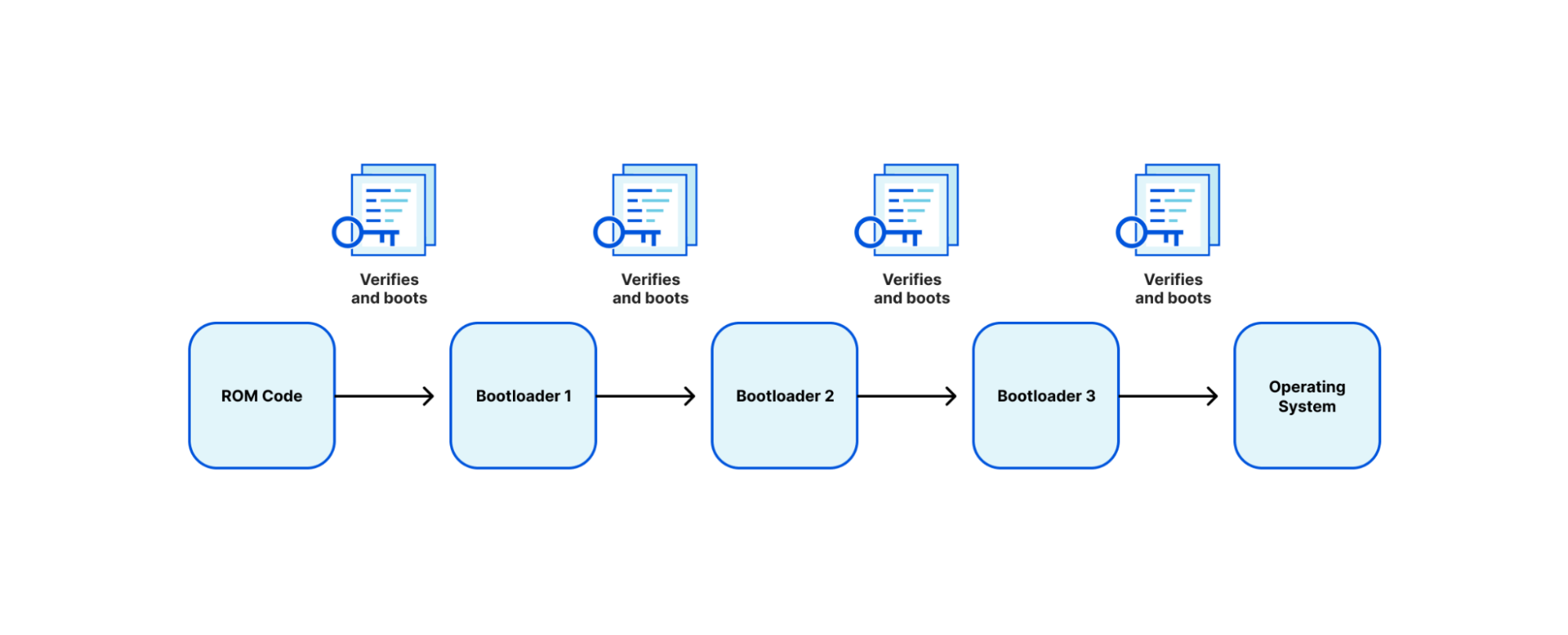
Arm defines a trusted boot process through an architecture called Trusted Board Boot Requirements (TBBR), or Arm Trusted Firmware (ATF) Secure Boot. TBBR works by authenticating a series of cryptographically signed binary images each containing a different stage or element in the system boot process to be loaded and executed. Every bootloader (BL) stage accomplishes a different stage in the initialization process:
BL1
BL1 defines the boot path (is this a cold boot or warm boot), initializes the architectures (exception vectors, CPU initialization, and control register setup), and initializes the platform (enables watchdog processes, MMU, and DDR initialization).
BL2
BL2 prepares initialization of the Arm Trusted Firmware (ATF), the stack responsible for setting up the secure boot process. After ATF setup, the console is initialized, memory is mapped for the MMU, and message buffers are set for the next bootloader.
BL3
The BL3 stage has multiple parts, the first being initialization of runtime services that are used in detecting system topology. After initialization, there is a handoff between the ATF ‘secure world’ boot stage to the ‘normal world’ boot stage that includes setup of UEFI firmware. Context is set up to ensure that no secure state information finds its way into the normal world execution state.
Each image is authenticated by a public key, which is stored in a signed certificate and can be traced back to a root key stored on the SoC in one time programmable (OTP) memory or ROM.
TBBR was originally designed for cell phones. This established a reference architecture on how to build a “Chain of Trust” from the first ROM executed (BL1) to the handoff to “normal world” firmware (BL3). While this creates a validated firmware signing chain, it has caveats:
SoC manufacturers are heavily involved in the secure boot chain, while the customer has little involvement.
A unique SoC SKU is required per customer. With one customer this could be easy, but most manufacturers have thousands of SKUs
The SoC manufacturer is primarily responsible for end-to-end signing and maintenance of the PKI chain. This adds complexity to the process requiring USB key fobs for signing.
Doesn’t scale outside the manufacturer.
What this tells us is what was built for cell phones doesn’t scale for servers.
If we were involved 100% in the manufacturing process, then this wouldn’t be as much of an issue, but we are a customer and consumer. As a customer, we have a lot of control of our server and block design, so we looked at design partners that would take some of the concepts we were able to implement with AMD Platform Secure Boot and refine them to fit Arm CPUs.
Amping it up
We partnered with Ampere and tested their Altra Max single socket rack server CPU (code named Mystique) that provides high performance with incredible power efficiency per core, much of what we were looking for in reducing power consumption. These are only a small subset of specs, but Ampere backported various features into the Altra Max notably, speculative attack mitigations that include Meltdown and Spectre (variants 1 and 2) from the Armv8.5 instruction set architecture, giving Altra the “+” designation in their ISA.
Ampere does implement a signed boot process similar to the ATF signing process mentioned above, but with some slight variations. We’ll explain it a bit to help set context for the modifications that we made.
Ampere Secure Boot
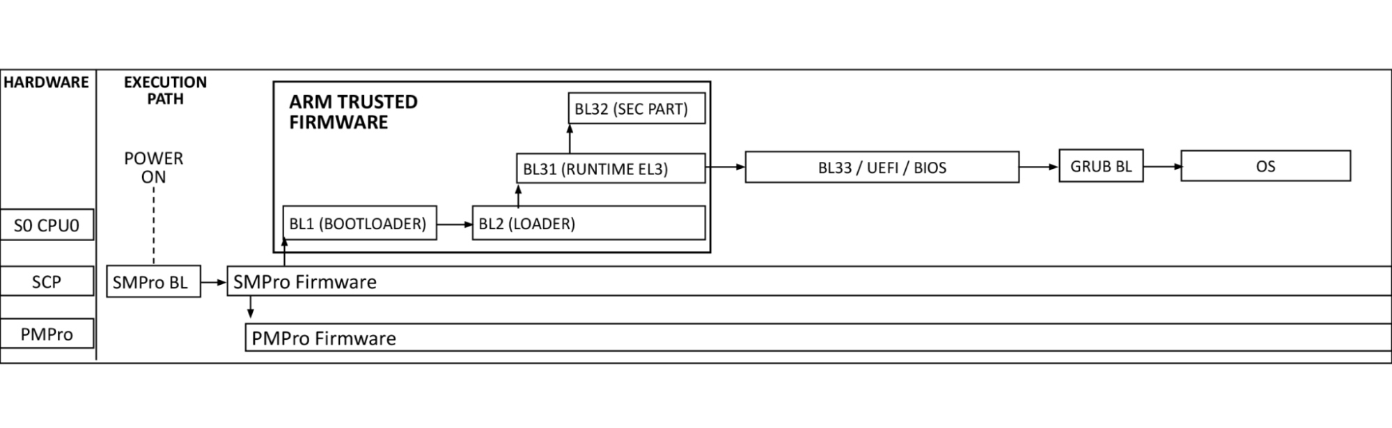
The diagram above shows the Arm processor boot sequence as implemented by Ampere. System Control Processors (SCP) are comprised of the System Management Processor (SMpro) and the Power Management Processor (PMpro). The SMpro is responsible for features such as secure boot and bmc communication while the PMpro is responsible for power features such as Dynamic Frequency Scaling and on-die thermal monitoring.
At power-on-reset, the SCP runs the system management bootloader from ROM and loads the SMpro firmware. After initialization, the SMpro spawns the power management stack on the PMpro and ATF threads. The ATF BL2 and BL31 bring up processor resources such as DRAM, and PCIe. After this, control is passed to BL33 BIOS.
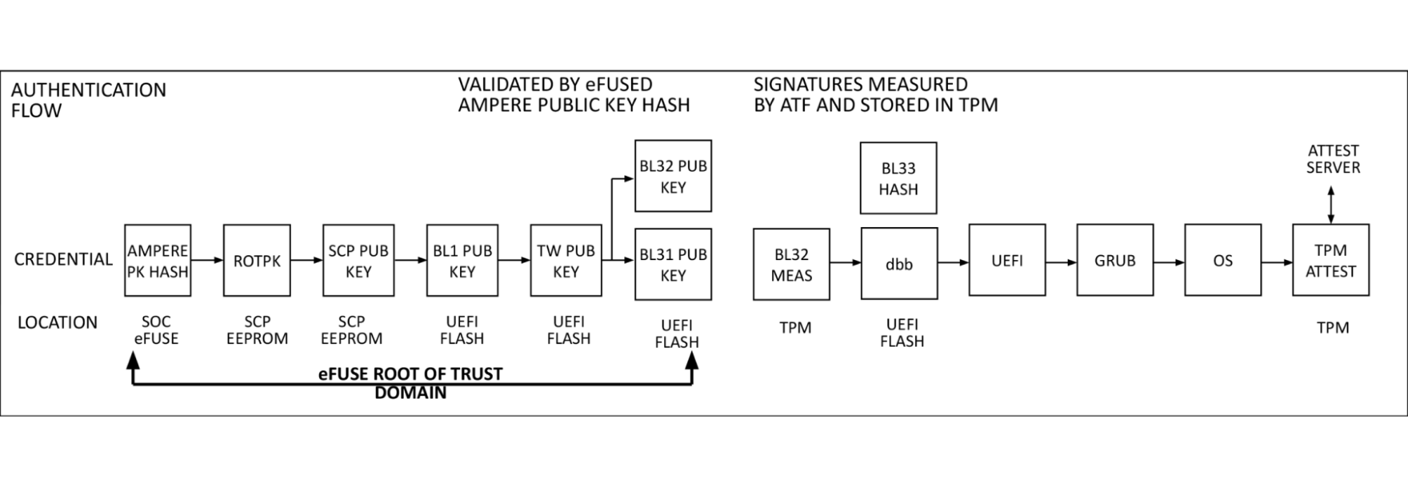
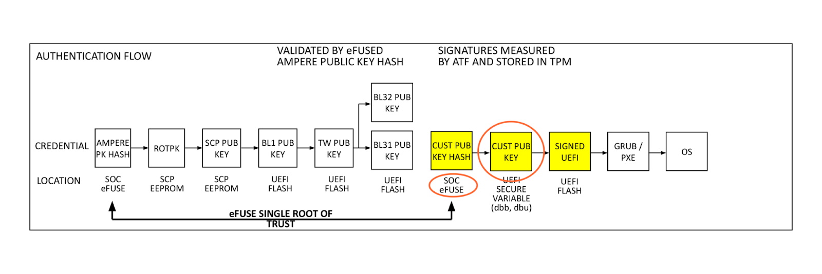
Authentication flow
At power on, the SMpro firmware reads Ampere’s public key (ROTPK) from the SMpro key certificate in SCP EEPROM, computes a hash and compares this to Ampere’s public key hash stored in eFuse. Once authenticated, Ampere’s public key is used to decrypt key and content certificates for SMpro, PMpro, and ATF firmware, which are launched in the order described above.
The SMpro public key will be used to authenticate the SMpro and PMpro images and ATF keys which in turn will authenticate ATF images. This cascading set of authentication that originates with the Ampere root key and stored in chip called an electronic fuse, or eFuse. An eFuse can be programmed only once, setting the content to be read-only and can not be tampered with nor modified.
This is the original hardware root of trust used for signing system, secure world firmware. When we looked at this, after referencing the signing process we had with AMD PSB and knowing there was a large enough one-time-programmable (OTP) region within the SoC, we thought: why can’t we insert our key hash in here?
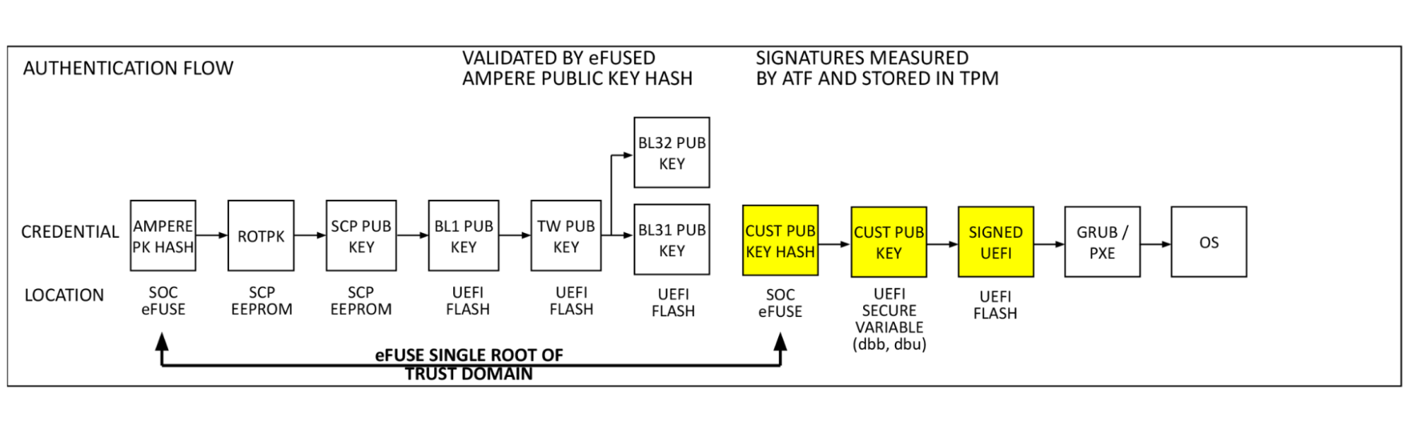
Single Domain Secure Boot
Single Domain Secure Boot takes the same authentication flow and adds a hash of the customer public key (Cloudflare firmware signing key in this case) to the eFuse domain. This enables the verification of UEFI firmware by a hardware root of trust. This process is performed in the already validated ATF firmware by BL2. Our public key (dbb) is read from UEFI secure variable storage, a hash is computed and compared to the public key hash stored in eFuse. If they match, the validated public key is used to decrypt the BL33 content certificate, validating and launching the BIOS, and remaining boot items. This is the key feature added by SDSB. It validates the entire software boot chain with a single eFuse root of trust on the processor.
Building blocks
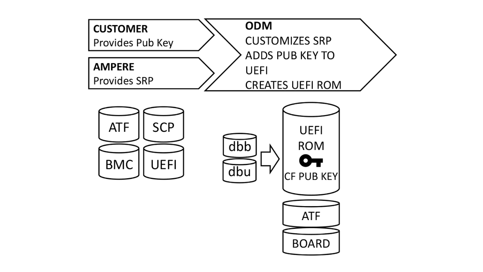
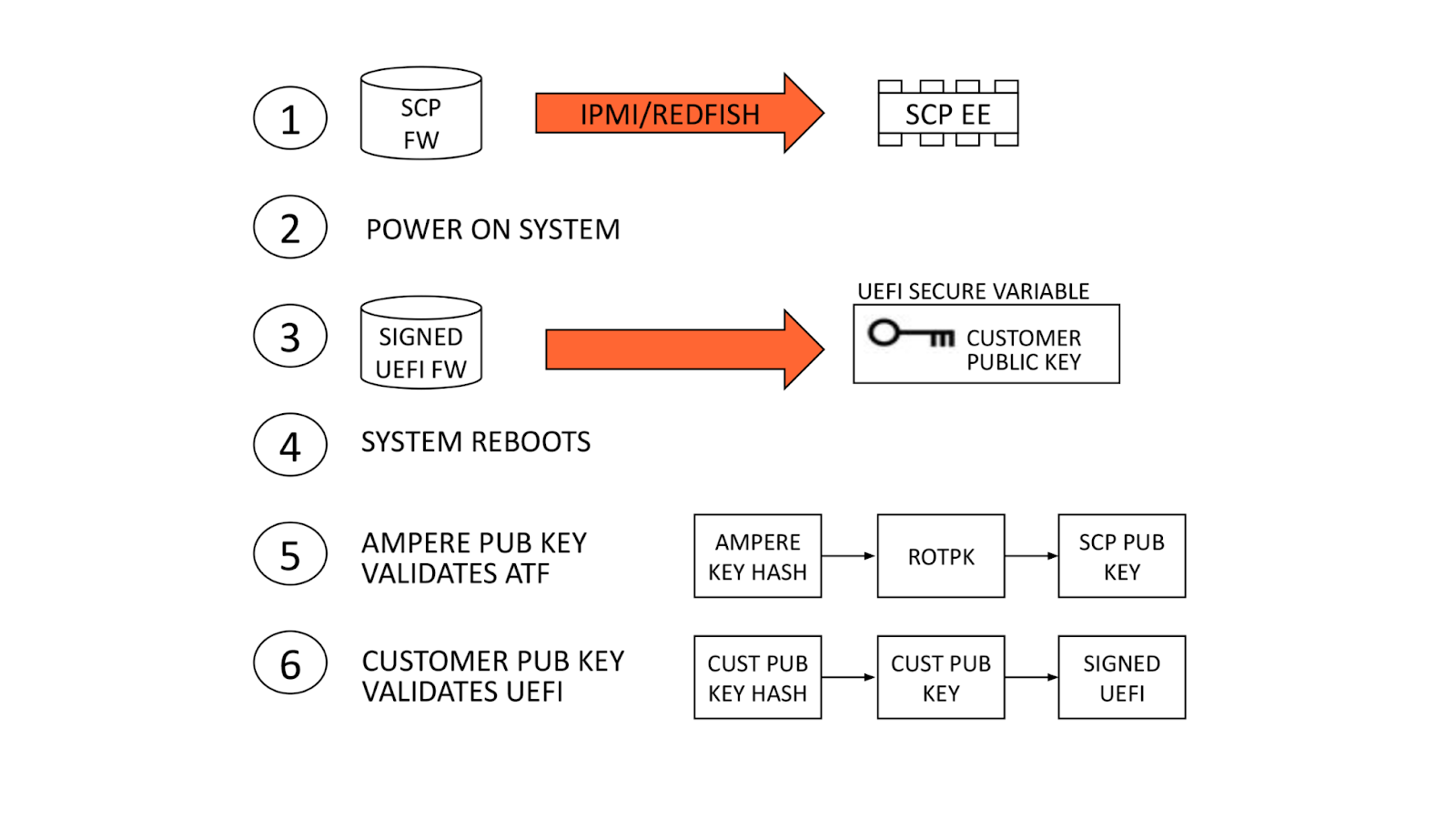
With a basic understanding of how Single Domain Secure Boot works, the next logical question is “How does it get implemented?”. We ensure that all UEFI firmware is signed at build time, but this process can be better understood if broken down into steps.
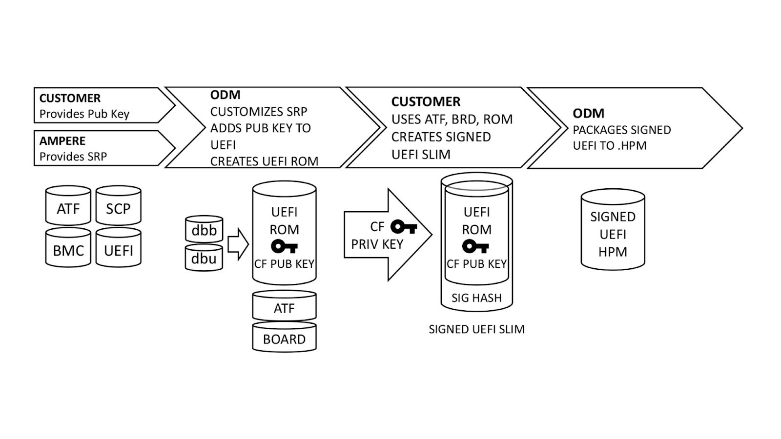
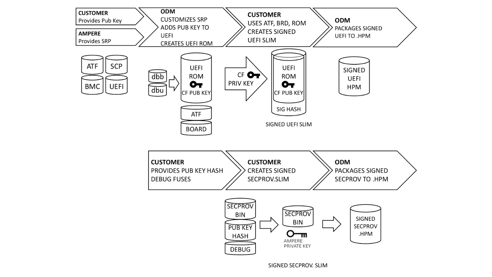
Ampere, our original device manufacturer (ODM), and we play a role in execution of SDSB. First, we generate certificates for a public-private key pair using our internal, secure PKI. The public key side is provided to the ODM as dbb.auth and dbu.auth in UEFI secure variable format. Ampere provides a reference Software Release Package (SRP) including the baseboard management controller, system control processor, UEFI, and complex programmable logic device (CPLD) firmware to the ODM, who customizes it for their platform. The ODM generates a board file describing the hardware configuration, and also customizes the UEFI to enroll dbb and dbu to secure variable storage on first boot.
Once this is done, we generate a UEFI.slim file using the ODM’s UEFI ROM image, Arm Trusted Firmware (ATF) and Board File. (Note: This differs from AMD PSB insofar as the entire image and ATF files are signed; with AMD PSB, only the first block of boot code is signed.) The entire .SLIM file is signed with our private key, producing a signature hash in the file. This can only be authenticated by the correct public key. Finally, the ODM packages the UEFI into .HPM format compatible with their platform BMC.
In parallel, we provide the debug fuse selection and hash of our DER-formatted public key. Ampere uses this information to create a special version of the SCP firmware known as Security Provisioning (SECPROV) .slim format. This firmware is run one time only, to program the debug fuse settings and public key hash into the SoC eFuses. Ampere delivers the SECPROV .slim file to the ODM, who packages it into a .hpm file compatible with the BMC firmware update tooling.
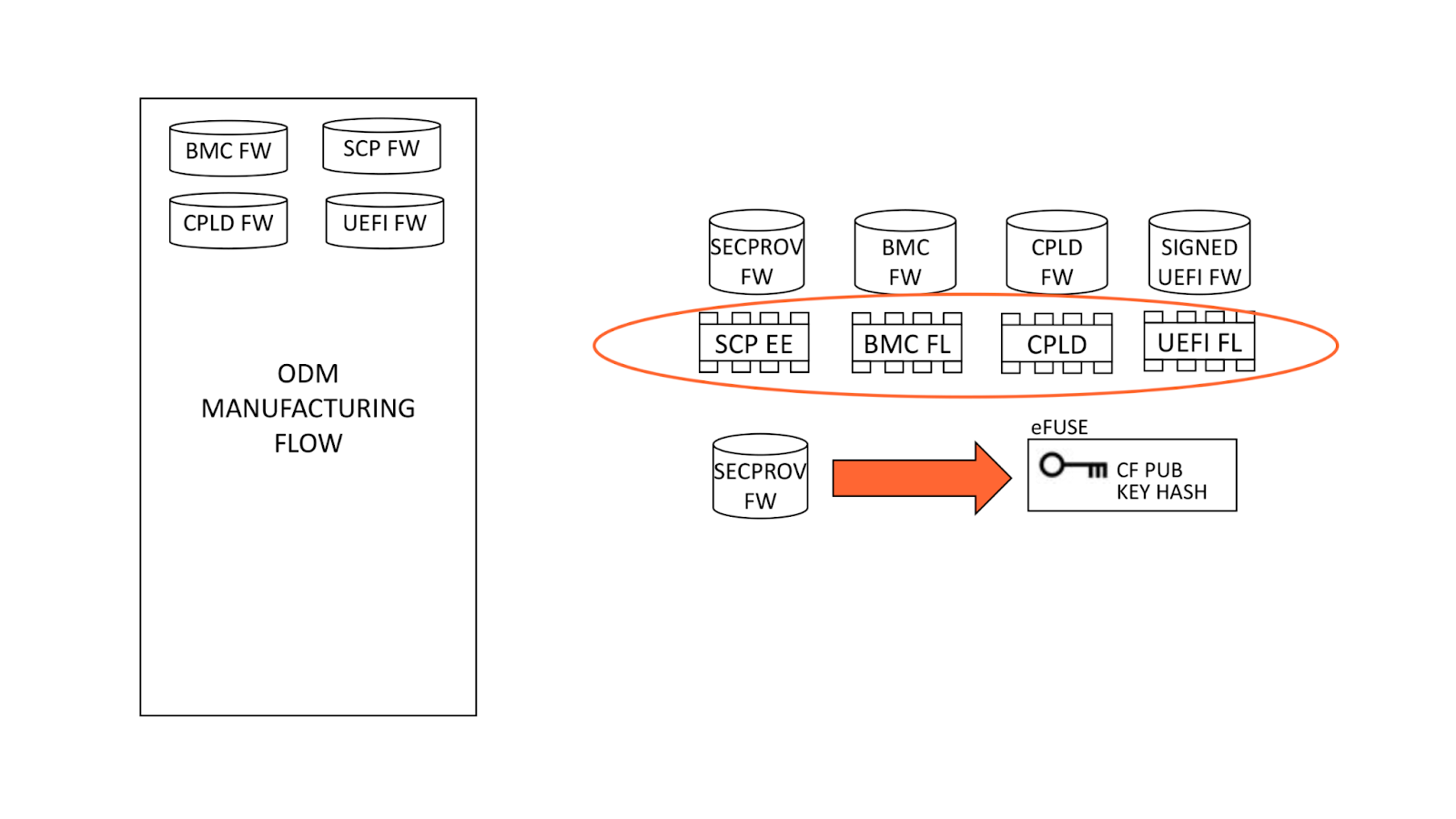
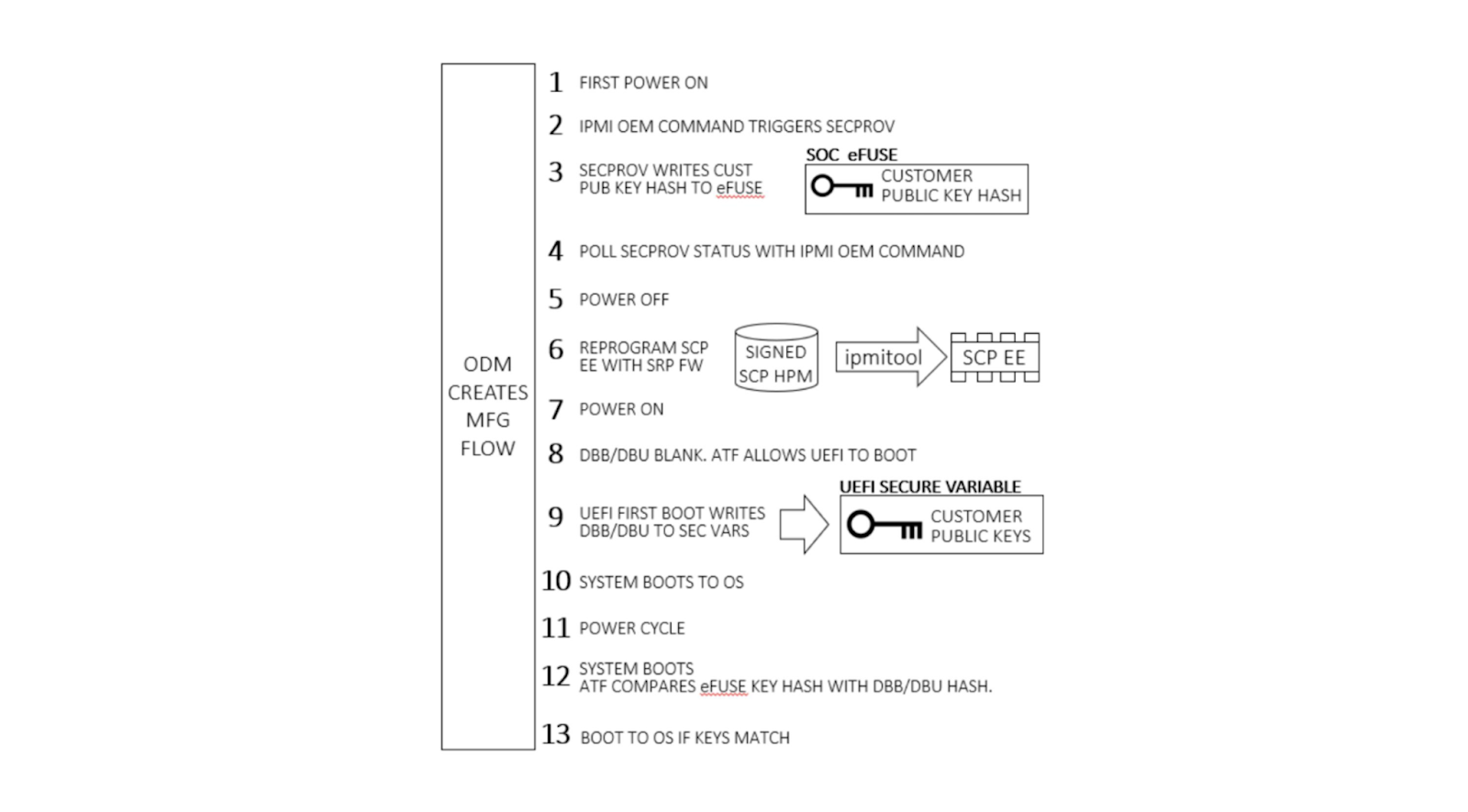
Fusing the keys
During system manufacturing, firmware is pre-programmed into storage ICs before placement on the motherboard. Note that the SCP EEPROM contains the SECPROV image, not standard SCP firmware. After a system is first powered on, an IPMI command is sent to the BMC which releases the Ampere processor from reset. This allows SECPROV firmware to run, burning the SoC eFuse with our public key hash and debug fuse settings.
Final manufacturing flow
Once our public key has been provisioned, manufacturing proceeds by re-programming the SCP EEPROM with its regular firmware. Once the system powers on, ATF detects there are no keys present in secure variable storage and allows UEFI firmware to boot, regardless of signature. Since this is the first UEFI boot, it programs our public key into secure variable storage and reboots. ATF is validated by Ampere’s public key hash as usual. Since our public key is present in dbb, it is validated against our public key hash in eFuse and allows UEFI to boot.
Validation
The first part of validation requires observing successful destruction of the eFuses. This imprints our public key hash into a dedicated, immutable memory region, not allowing the hash to be overwritten. Upon automatic or manual issue of an IPMI OEM command to the BMC, the BMC observes a signal from the SECPROV firmware, denoting eFuse programming completion. This can be probed with BMC commands.
When the eFuses have been blown, validation continues by observing the boot chain of the other firmware. Corruption of the SCP, ATF, or UEFI firmware obstructs boot flow and boot authentication and will cause the machine to fail booting to the OS. Once firmware is in place, happy path validation begins with booting the machine.
Upon first boot, firmware boots in the following order: BMC, SCP, ATF, and UEFI. The BMC, SCP, and ATF firmware can be observed via their respective serial consoles. The UEFI will automatically enroll the dbb and dbu files to the secure variable storage and trigger a reset of the system.
After observing the reset, the machine should successfully boot to the OS if the feature is executed correctly. For further validation, we can use the UEFI shell environment to extract the dbb file and compare the hash against the hash submitted to Ampere. After successfully validating the keys, we flash an unsigned UEFI image. An unsigned UEFI image causes authentication failure at bootloader stage BL3-2. The ATF firmware undergoes a boot loop as a result. Similar results will occur for a UEFI image signed with incorrect keys.
Updated authentication flow
On all subsequent boot cycles, the ATF will read secure variable dbb (our public key), compute a hash of the key, and compare it to the read-only Cloudflare public key hash in eFuse. If the computed and eFuse hashes match, our public key variable can be trusted and is used to authenticate the signed UEFI. After this, the system boots to the OS.
Let’s boot!
We were unable to get a machine without the feature enabled to demonstrate the set-up of the feature since we have the eFuse set at build time, but we can demonstrate what it looks like to go between an unsigned BIOS and a signed BIOS. What we would have observed with the set-up of the feature is a custom BMC command to instruct the SCP to burn the ROTPK into the SOC’s OTP fuses. From there, we would observe feedback to the BMC detailing whether burning the fuses was successful. Upon booting the UEFI image for the first time, the UEFI will write the dbb and dbu into secure storage.
As you can see, after flashing the unsigned BIOS, the machine fails to boot.
Despite the lack of visibility in failure to boot, there are a few things going on underneath the hood. The SCP (System Control Processor) still boots.
The SCP image holds a key certificate with Ampere’s generated ROTPK and the SCP key hash. SCP will calculate the ROTPK hash and compare it against the burned OTP fuses. In the failure case, where the hash does not match, you will observe a failure as you saw earlier. If successful, the SCP firmware will proceed to boot the PMpro and SMpro. Both the PMpro and SMpro firmware will be verified and proceed with the ATF authentication flow.
The conclusion of the SCP authentication is the passing of the BL1 key to the first stage bootloader via the SCP HOB(hand-off-block) to proceed with the standard three stage bootloader ATF authentication mentioned previously.
At BL2, the dbb is read out of the secure variable storage and used to authenticate the BL33 certificate and complete the boot process by booting the BL33 UEFI image.
Still more to do
In recent years, management interfaces on servers, like the BMC, have been the target of cyber attacks including ransomware, implants, and disruptive operations. Access to the BMC can be local or remote. With remote vectors open, there is potential for malware to be installed on the BMC via network interfaces. With compromised software on the BMC, malware or spyware could maintain persistence on the server. An attacker might be able to update the BMC directly using flashing tools such as flashrom or socflash without the same level of firmware resilience established at the UEFI level.
The future state involves using host CPU-agnostic infrastructure to enable a cryptographically secure host prior to boot time. We will look to incorporate a modular approach that has been proposed by the Open Compute Project’s Data Center Secure Control
Module Specification (DC-SCM) 2.0 specification. This will allow us to standardize our Root of Trust, sign our BMC, and assign physically unclonable function (PUF) based identity keys to components and peripherals to limit the use of OTP fusing. OTP fusing creates a problem with trying to “e-cycle” or reuse machines as you cannot truly remove a machine identity.
In recent years, management interfaces on servers like a Baseboard Management Controller (BMC) have been the target of cyber attacks including ransomware, implants, and disruptive operations. Common BMC vulnerabilities like Pantsdown and USBAnywhere, combined with infrequent firmware updates, have left servers vulnerable.
We were recently informed from a trusted vendor of new, critical vulnerabilities in popular BMC software that we use in our fleet. Below is a summary of what was discovered, how we mitigated the impact, and how we look to prevent these types of vulnerabilities from having an impact on Cloudflare and our customers.
Background
A baseboard management controller is a small, specialized processor used for remote monitoring and management of a host system. This processor has multiple connections to the host system, giving it the ability to monitor hardware, update BIOS firmware, power cycle the host, and many more things.
Access to the BMC can be local or, in some cases, remote. With remote vectors open, there is potential for malware to be installed on the BMC from the local host via PCI Express or the Low Pin Count (LPC) interface. With compromised software on the BMC, malware or spyware could maintain persistence on the server.
According to the National Vulnerability Database, the two BMC chips (ASPEED AST2400 and AST2500) have implemented Advanced High-Performance Bus (AHB) bridges, which allow arbitrary read and write access to the physical address space of the BMC from the host. This means that malware running on the server can also access the RAM of the BMC.
These BMC vulnerabilities are sufficient to enable ransomware propagation, server bricking, and data theft.
Impacted versions
Numerous vulnerabilities were found to affect the QuantaGrid D52B cloud server due to vulnerable software found in the BMC. These vulnerabilities are associated with specific interfaces that are exposed on AST2400 and AST2500 and explained in CVE-2019-6260. The vulnerable interfaces in question are:
An attacker might be able to update the BMC directly using SoCFlash through inband LPC or BMC debug universal async receiver-transmitter (UART) serial console. While this might be thought of as a usual path in case of total corruption, this is actually an abuse within SoCFlash by using any open interface for flashing.
Mitigations and response
Updated firmware
We reached out to one of our manufacturers, Quanta, to validate that existing firmware within a subset of systems was in fact patched against these vulnerabilities. While some versions of our firmware were not vulnerable, others were. A patch was released, tested, and deployed on the affected BMCs within our fleet.
Cloudflare Security and Infrastructure teams also proactively worked with additional manufacturers to validate their own BMC patches were not explicitly vulnerable to these firmware vulnerabilities and interfaces.
Reduced exposure of BMC remote interfaces
It is a standard practice within our data centers to implement network segmentation to separate different planes of traffic. Our out-of-band networks are not exposed to the outside world and only accessible within their respective data centers. Access to any management network goes through a defense in depth approach, restricting connectivity to jumphosts and authentication/authorization through our zero trust Cloudflare One service.
Reduced exposure of BMC local interfaces
Applications within a host are limited in what can call out to the BMC. This is done to restrict what can be done from the host to the BMC and allow for secure in-band updating and userspace logging and monitoring.
Do not use default passwords
This sounds like common knowledge for most companies, but we still follow a standard process of changing not just the default username and passwords that come with BMC software, but disabling the default accounts to prevent them from ever being used. Any static accounts follow a regular password rotation.
BMC logging and auditing
We log all activity by default on our BMCs. Logs that are captured include the following:
Authentication (Successful, Unsuccessful)
Authorization (user/service)
Interfaces (SOL, CLI, UI)
System status (Power on/off, reboots)
System changes (firmware updates, flashing methods)
We were able to validate that there was no malicious activity detected.
What’s next for the BMC
Cloudflare regularly works with several original design manufacturers (ODMs) to produce the highest performing, efficient, and secure computing systems according to our own specifications. The standard processors used for our baseboard management controller often ship with proprietary firmware which is less transparent and more cumbersome to maintain for us and our ODMs. We believe in improving on every component of the systems we operate in over 270 cities around the world.
OpenBMC
We are moving forward with OpenBMC, an open-source firmware for our supported baseboard management controllers. Based on the Yocto Project, a toolchain for Linux on embedded systems, OpenBMC will enable us to specify, build, and configure our own firmware based on the latest Linux kernel featureset per our specification, similar to the physical hardware and ODMs.
OpenBMC firmware will enable:
Latest stable and patched Linux kernel
Internally-managed TLS certificates for secure, trusted communication across our isolated management network
Fine-grained credentials management
Faster response time for patching and critical updates
While many of these features are community-driven, vulnerabilities like Pantsdown are patched quickly.
Extending secure boot
You may have read about our recent work securing the boot process with a hardware root-of-trust, but the BMC has its own boot process that often starts as soon as the system gets power. Newer versions of the BMC chips we use, as well as leveraging cutting edgesecurity co-processors, will allow us to extend our secure boot capabilities prior to loading our UEFI firmware by validating cryptographic signatures on our BMC/OpenBMC firmware. By extending our security boot chain to the very first device that has power to our systems, we greatly reduce the impact of malicious implants that can be used to take down a server.
Conclusion
While this vulnerability ended up being one we could quickly resolve through firmware updates with Quanta and quick action by our teams to validate and patch our fleet, we are continuing to innovate through OpenBMC, and secure root of trust to ensure that our fleet is as secure as possible. We are grateful to our partners for their quick action and are always glad to report any risks and our mitigations to ensure that you can trust how seriously we take your security.
As a security company, we pride ourselves on finding innovative ways to protect our platform to, in turn, protect the data of our customers. Part of this approach is implementing progressive methods in protecting our hardware at scale. While we have blogged about how we address security threats from application to memory, the attacks on hardware, as well as firmware, have increased substantially. The data cataloged in the National Vulnerability Database (NVD) has shown the frequency of hardware and firmware-level vulnerabilities rising year after year.
Technologies like secure boot, common in desktops and laptops, have been ported over to the server industry as a method to combat firmware-level attacks and protect a device’s boot integrity. These technologies require that you create a trust ‘anchor’, an authoritative entity for which trust is assumed and not derived. A common trust anchor is the system Basic Input/Output System (BIOS) or the Unified Extensible Firmware Interface (UEFI) firmware.
While this ensures that the device boots only signed firmware and operating system bootloaders, does it protect the entire boot process? What protects the BIOS/UEFI firmware from attacks?
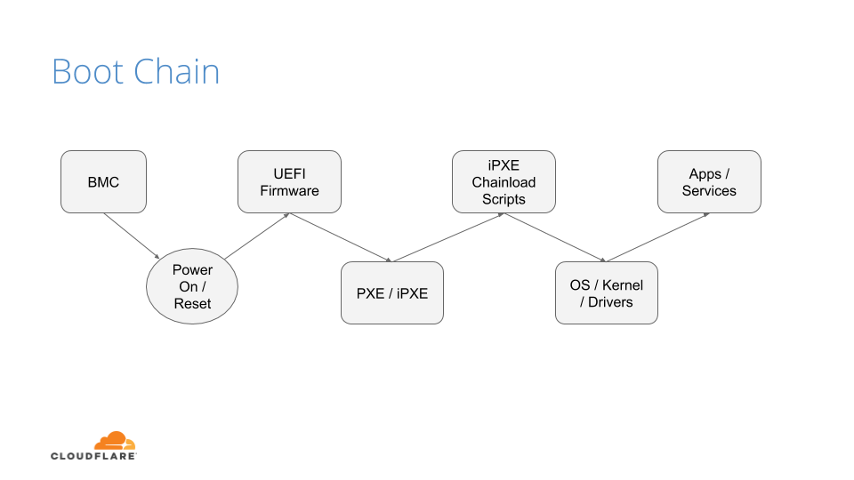
The Boot Process
Before we discuss how we secure our boot process, we will first go over how we boot our machines.
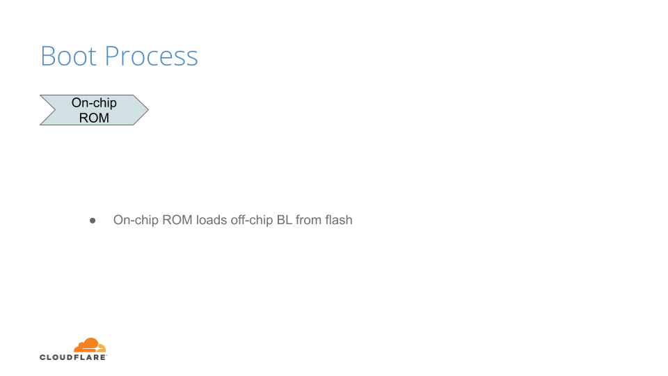
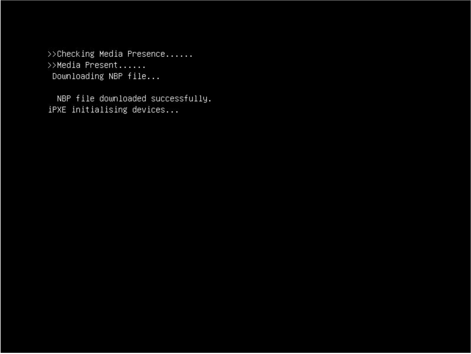
The above image shows the following sequence of events:
After powering on the system (through a baseboard management controller (BMC) or physically pushing a button on the system), the system unconditionally executes the UEFI firmware residing on a flash chip on the motherboard.
UEFI performs some hardware and peripheral initialization and executes the Preboot Execution Environment (PXE) code, which is a small program that boots an image over the network and usually resides on a flash chip on the network card.
PXE sets up the network card, and downloads and executes a small program bootloader through an open source boot firmware called iPXE.
iPXE loads a script that automates a sequence of commands for the bootloader to know how to boot a specific operating system (sometimes several of them). In our case, it loads our Linux kernel, initrd (this contains device drivers which are not directly compiled into the kernel), and a standard Linux root filesystem. After loading these components, the bootloader executes and hands off the control to the kernel.
Finally, the Linux kernel loads any additional drivers it needs and starts applications and services.
UEFI Secure Boot
Our UEFI secure boot process is fairly straightforward, albeit customized for our environments. After loading the UEFI firmware from the bootloader, an initialization script defines the following variables:
Platform Key (PK): It serves as the cryptographic root of trust for secure boot, giving capabilities to manipulate and/or validate the other components of the secure boot framework.
Trusted Database (DB): Contains a signed (by platform key) list of hashes of all PCI option ROMs, as well as a public key, which is used to verify the signature of the bootloader and the kernel on boot.
These variables are respectively the master platform public key, which is used to sign all other resources, and an allow list database, containing other certificates, binary file hashes, etc. In default secure boot scenarios, Microsoft keys are used by default. At Cloudflare we use our own, which makes us the root of trust for UEFI:
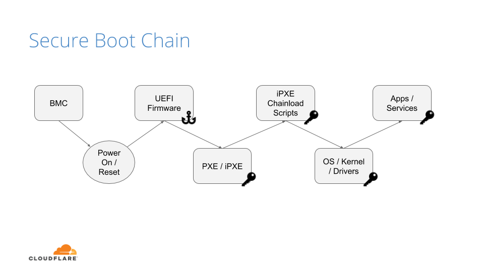
But, by setting our trust anchor in the UEFI firmware, what attack vectors still exist?
UEFI Attacks
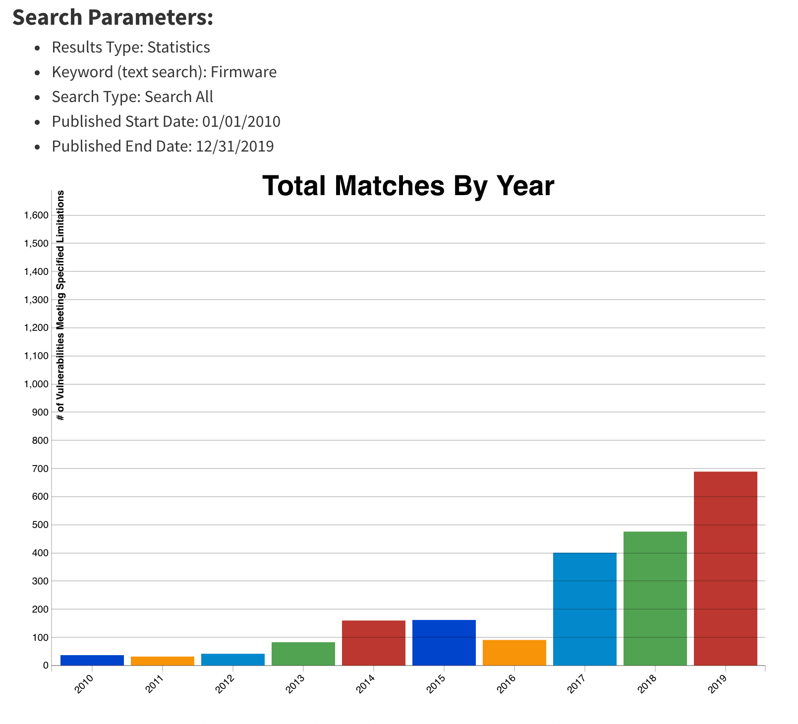
As stated previously, firmware and hardware attacks are on the rise. It is clear from the figure below that firmware-related vulnerabilities have increased significantly over the last 10 years, especially since 2017, when the hacker community started attacking the firmware on different platforms:
This upward trend, coupled with recent malware findings in UEFI, shows that trusting firmware is becoming increasingly problematic.
By tainting the UEFI firmware image, you poison the entire boot trust chain. The ability to trust firmware integrity is important beyond secure boot. For example, if you can’t trust the firmware not to be compromised, you can’t trust things like trusted platform module (TPM) measurements to be accurate, because the firmware is itself responsible for doing these measurements (e.g a TPM is not an on-path security mechanism, but instead it requires firmware to interact and cooperate with). Firmware may be crafted to extend measurements that are accepted by a remote attestor, but that don’t represent what’s being locally loaded. This could cause firmware to have a questionable measured boot and remote attestation procedure.
If we can’t trust firmware, then hardware becomes our last line of defense.
Hardware Root of Trust
Early this year, we made a series of blog posts on why we chose AMD EPYC processors for our Gen X servers. With security in mind, we started turning on features that were available to us and set forth the plan of using AMD silicon as a Hardware Root of Trust (HRoT).
Platform Secure Boot (PSB) is AMD’s implementation of hardware-rooted boot integrity. Why is it better than UEFI firmware-based root of trust? Because it is intended to assert, by a root of trust anchored in the hardware, the integrity and authenticity of the System ROM image before it can execute. It does so by performing the following actions:
Authenticates the first block of BIOS/UEFI prior to releasing x86 CPUs from reset.
Authenticates the System Read-Only Memory (ROM) contents on each boot, not just during updates.
Moves the UEFI Secure Boot trust chain to immutable hardware.
This is accomplished by the AMD Platform Security Processor (PSP), an ARM Cortex-A5 microcontroller that is an immutable part of the system on chip (SoC). The PSB consists of two components:
On-chip Boot ROM
Embeds a SHA384 hash of an AMD root signing key
Verifies and then loads the off-chip PSP bootloader located in the boot flash
Off-chip Bootloader
Locates the PSP directory table that allows the PSP to find and load various images
Authenticates first block of BIOS/UEFI code
Releases CPUs after successful authentication
The PSP secures the On-chip Boot ROM code, loads the off-chip PSP firmware into PSP static random access memory (SRAM) after authenticating the firmware, and passes control to it.
The Off-chip Bootloader (BL) loads and specifies applications in a specific order (whether or not the system goes into a debug state and then a secure EFI application binary interface to the BL)
The system continues initialization through each bootloader stage.
If each stage passes, then the UEFI image is loaded and the x86 cores are released.
Now that we know the booting steps, let’s build an image.
Build Process
Public Key Infrastructure
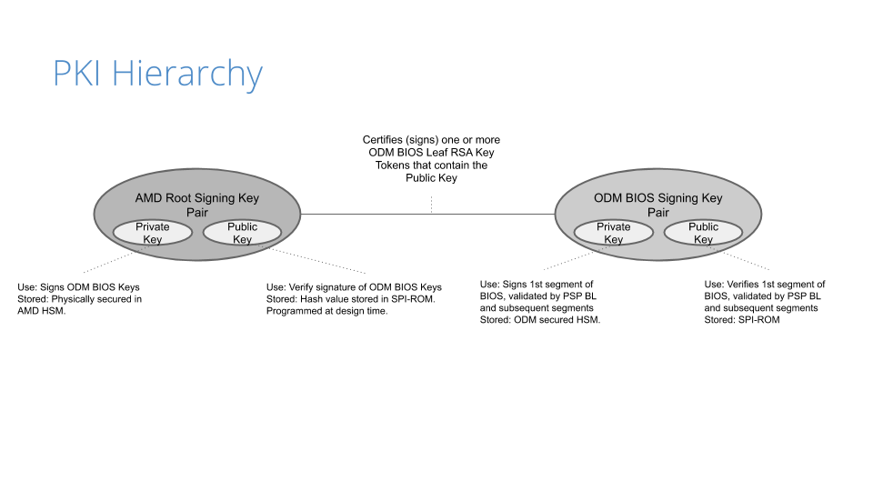
Before the image gets built, a public key infrastructure (PKI) is created to generate the key pairs involved for signing and validating signatures:
Our original device manufacturer (ODM), as a trust extension, creates a key pair (public and private) that is used to sign the first segment of the BIOS (private key) and validates that segment on boot (public key).
On AMD’s side, they have a key pair that is used to sign (the AMD root signing private key) and certify the public key created by the ODM. This is validated by AMD’s root signing public key, which is stored as a hash value (RSASSA-PSS: SHA-384 with 4096-bit key is used as the hashing algorithm for both message and mask generation) in SPI-ROM.
Because of the way the PKI mechanisms are built, the system cannot be compromised if only one of the keys is leaked. This is an important piece of the trust hierarchy that is used for image signing.
Certificate Signing Request
Once the PKI infrastructure is established, a BIOS signing key pair is created, together with a certificate signing request (CSR). Creating the CSR uses known common name (CN) fields that many are familiar with:
countryName
stateOrProvinceName
localityName
organizationName
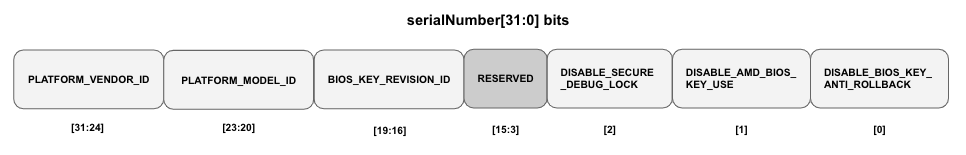
In addition to the fields above, the CSR will contain a serialNumber field, a 32-bit integer value represented in ASCII HEX format that encodes the following values:
PLATFORM_VENDOR_ID: An 8-bit integer value assigned by AMD for each ODM.
PLATFORM_MODEL_ID: A 4-bit integer value assigned to a platform by the ODM.
BIOS_KEY_REVISION_ID: is set by the ODM encoding a 4-bit key revision as unary counter value.
DISABLE_SECURE_DEBUG: Fuse bit that controls whether secure debug unlock feature is disabled permanently.
DISABLE_AMD_BIOS_KEY_USE: Fuse bit that controls if the BIOS, signed by an AMD key, (with vendor ID == 0) is permitted to boot on a CPU with non-zero Vendor ID.
DISABLE_BIOS_KEY_ANTI_ROLLBACK: Fuse bit that controls whether BIOS key anti-rollback feature is enabled.
Remember these values, as we’ll show how we use them in a bit. Any of the DISABLE values are optional, but recommended based on your security posture/comfort level.
AMD, upon processing the CSR, provides the public part of the BIOS signing key signed and certified by the AMD signing root key as a RSA Public Key Token file (.stkn) format.
Putting It All Together
The following is a step-by-step illustration of how signed UEFI firmware is built:
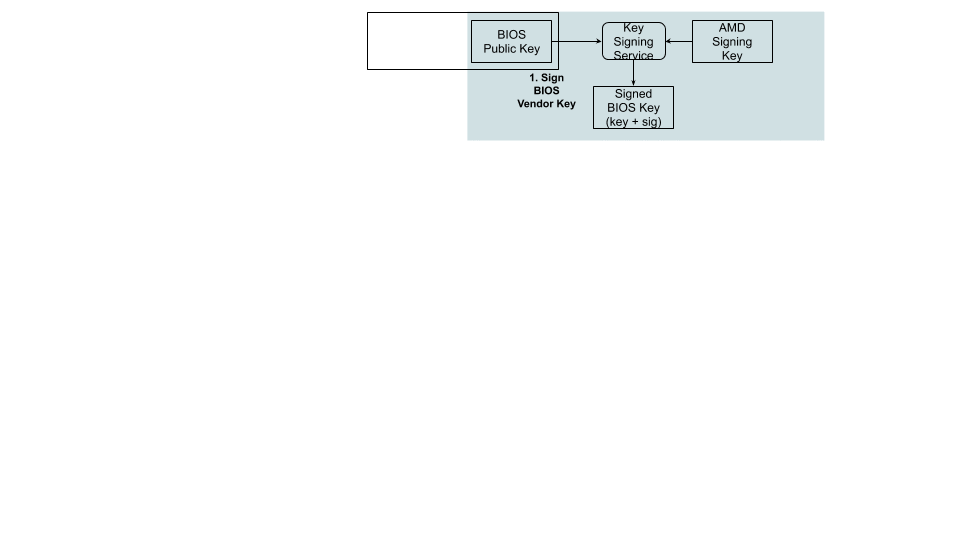
The ODM submits their public key used for signing Cloudflare images to AMD.
AMD signs this key using their RSA private key and passes it back to ODM.
The AMD public key and the signed ODM public key are part of the final BIOS SPI image.
The BIOS source code is compiled and various BIOS components (PEI Volume, Driver eXecution Environment (DXE) volume, NVRAM storage, etc.) are built as usual.
The PSP directory and BIOS directory are built next. PSP directory and BIOS directory table points to the location of various firmware entities.
The ODM builds the signed BIOS Root of Trust Measurement (RTM) signature based on the blob of BIOS PEI volume concatenated with BIOS Directory header, and generates the digital signature of this using the private portion of ODM signing key. The SPI location for signed BIOS RTM code is finally updated with this signature blob.
Finally, the BIOS binaries, PSP directory, BIOS directory and various firmware binaries are combined to build the SPI BIOS image.
Enabling Platform Secure Boot
Platform Secure Boot is enabled at boot time with a PSB-ready firmware image. PSB is configured using a region of one-time programmable (OTP) fuses, specified for the customer. OTP fuses are on-chip non-volatile memory (NVM) that permits data to be written to memory only once. There is NO way to roll the fused CPU back to an unfused one.
Enabling PSB in the field will go through two steps: fusing and validating.
Fusing: Fuse the values assigned in the serialNumber field that was generated in the CSR
Validating: Validate the fused values and the status code registers
If validation is successful, the BIOS RTM signature is validated using the ODM BIOS signing key, PSB-specific registers (MP0_C2P_MSG_37 and MP0_C2P_MSG_38) are updated with the PSB status and fuse values, and the x86 cores are released
If validation fails, the registers above are updated with the PSB error status and fuse values, and the x86 cores stay in a locked state.
Let’s Boot!
With a signed image in hand, we are ready to enable PSB on a machine. We chose to deploy this on a few machines that had an updated, unsigned AMI UEFI firmware image, in this case version 2.16. We use a couple of different firmware updatetools, so, after a quick script, we ran an update to change the firmware version from 2.16 to 2.18C (the signed image):
. $sudo ./UpdateAll.sh
Bin file name is ****.218C

BEGIN

+---------------------------------------------------------------------------+
|                 AMI Firmware Update Utility v5.11.03.1778                 |
|                 Copyright (C)2018 American Megatrends Inc.                |
|                         All Rights Reserved.                              |
+---------------------------------------------------------------------------+
Reading flash ............... done
FFS checksums ......... ok
Check RomLayout ........ ok.
Erasing Boot Block .......... done
Updating Boot Block ......... done
Verifying Boot Block ........ done
Erasing Main Block .......... done
Updating Main Block ......... done
Verifying Main Block ........ done
Erasing NVRAM Block ......... done
Updating NVRAM Block ........ done
Verifying NVRAM Block ....... done
Erasing NCB Block ........... done
Updating NCB Block .......... done
Verifying NCB Block ......... done

Process completed.
After the update completed, we rebooted:
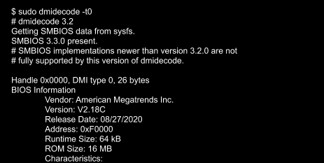
After a successful install, we validated that the image was correct via the sysfs information provided in the dmidecode output:
Testing
With a signed image installed, we wanted to test that it worked, meaning: what if an unauthorized user installed their own firmware image? We did this by downgrading the image back to an unsigned image, 2.16. In theory, the machine shouldn’t boot as the x86 cores should stay in a locked state. After downgrading, we rebooted and got the following:
This isn’t a powered down machine, but the result of booting with an unsigned image.
Flashing back to a signed image is done by running the same flashing utility through the BMC, so we weren’t bricked. Nonetheless, the results were successful.
Naming Convention
Our standard UEFI firmware images are alphanumeric, making it difficult to distinguish (by name) the difference between a signed and unsigned image (v2.16A vs v2.18C), for example. There isn’t a remote attestation capability (yet) to probe the PSB status registers or to store these values by means of a signature (e.g. TPM quote). As we transitioned to PSB, we wanted to make this easier to determine by adding a specific suffix: -sig that we could query in userspace. This would allow us to query this information via Prometheus. Changing the file name alone wouldn’t do it, so we had to make the following changes to reflect a new naming convention for signed images:
Update filename
Update BIOS version for setup menu
Update post message
Update SMBIOS type 0 (BIOS version string identifier)
Signed images now have a -sig suffix:
~$ sudo dmidecode -t0
# dmidecode 3.2
Getting SMBIOS data from sysfs.
SMBIOS 3.3.0 present.
# SMBIOS implementations newer than version 3.2.0 are not
# fully supported by this version of dmidecode.

Handle 0x0000, DMI type 0, 26 bytes
BIOS Information
	Vendor: American Megatrends Inc.
	Version: V2.20-sig
	Release Date: 09/29/2020
	Address: 0xF0000
	Runtime Size: 64 kB
	ROM Size: 16 MB
Conclusion
Finding weaknesses in firmware is a challenge that many attackers have taken on. Attacks that physically manipulate the firmware used for performing hardware initialization during the booting process can invalidate many of the common secure boot features that are considered industry standard. By implementing a hardware root of trust that is used for code signing critical boot entities, your hardware becomes a ‘first line of defense’ in ensuring that your server hardware and software integrity can derive trust through cryptographic means.
What’s Next?
While this post discussed our current, AMD-based hardware platform, how will this affect our future hardware generations? One of the benefits of working with diverse vendors like AMD and Ampere (ARM) is that we can ensure they are baking in our desired platform security by default (which we’ll speak about in a future post), making our hardware security outlook that much brighter 😀.
The collective thoughts of the interwebz
Manage Consent
To provide the best experiences, we use technologies like cookies to store and/or access device information. Consenting to these technologies will allow us to process data such as browsing behavior or unique IDs on this site. Not consenting or withdrawing consent, may adversely affect certain features and functions.
Functional
Always active
The technical storage or access is strictly necessary for the legitimate purpose of enabling the use of a specific service explicitly requested by the subscriber or user, or for the sole purpose of carrying out the transmission of a communication over an electronic communications network.
Preferences
The technical storage or access is necessary for the legitimate purpose of storing preferences that are not requested by the subscriber or user.
Statistics
The technical storage or access that is used exclusively for statistical purposes.The technical storage or access that is used exclusively for anonymous statistical purposes. Without a subpoena, voluntary compliance on the part of your Internet Service Provider, or additional records from a third party, information stored or retrieved for this purpose alone cannot usually be used to identify you.
Marketing
The technical storage or access is required to create user profiles to send advertising, or to track the user on a website or across several websites for similar marketing purposes.