An AS-SET, not to be confused with the recently deprecated BGP AS_SET, is an Internet Routing Registry (IRR) object that allows network operators to group related networks together. AS-SETs have been used historically for multiple purposes such as grouping together a list of downstream customers of a particular network provider. For example, Cloudflare uses the AS13335:AS-CLOUDFLARE AS-SET to group together our list of our own Autonomous System Numbers (ASNs) and our downstream Bring-Your-Own-IP (BYOIP) customer networks, so we can ultimately communicate to other networks whose prefixes they should accept from us.
In other words, an AS-SET is currently the way on the Internet that allows someone to attest the networks for which they are the provider. This system of provider authorization is completely trust-based, meaning it’s not reliable at all, and is best-effort. The future of an RPKI-based provider authorization system is coming in the form of ASPA (Autonomous System Provider Authorization), but it will take time for standardization and adoption. Until then, we are left with AS-SETs.
Because AS-SETs are so critical for BGP routing on the Internet, network operators need to be able to monitor valid and invalid AS-SET memberships for their networks. Cloudflare Radar now introduces a transparent, public listing to help network operators in our routing page per ASN.
AS-SETs and building BGP route filters
AS-SETs are a critical component of BGP policies, and often paired with the expressive Routing Policy Specification Language (RPSL) that describes how a particular BGP ASN accepts and propagates routes to other networks. Most often, networks use AS-SET to express what other networks should accept from them, in terms of downstream customers.
Back to the AS13335:AS-CLOUDFLARE example AS-SET, this is published clearly on PeeringDB for other peering networks to reference and build filters against.
When turning up a new transit provider service, we also ask the provider networks to build their route filters using the same AS-SET. Because BGP prefixes are also created in IRR registries using the route or route6 objects, peers and providers now know what BGP prefixes they should accept from us and deny the rest. A popular tool for building prefix-lists based on AS-SETs and IRR databases is bgpq4, and it’s one you can easily try out yourself.
For example, to generate a Juniper router’s IPv4 prefix-list containing prefixes that AS13335 could propagate for Cloudflare and its customers, you may use:
Restricted to 10 lines, actual output of prefix-list would be much greater
This prefix list would be applied within an eBGP import policy by our providers and peers to make sure AS13335 is only able to propagate announcements for ourselves and our customers.
How accurate AS-SETs prevent route leaks
Let’s see how accurate AS-SETs can help prevent route leaks with a simple example. In this example, AS64502 has two providers – AS64501 and AS64503. AS64502 has accidentally messed up their BGP export policy configuration toward the AS64503 neighbor, and is exporting all routes, including those it receives from their AS64501 provider. This is a typical Type 1 Hairpin route leak.
Fortunately, AS64503 has implemented an import policy that they generated using IRR data including AS-SETs and route objects. By doing so, they will only accept the prefixes that originate from the AS Cone of AS64502, since they are their customer. Instead of having a major reachability or latency impact for many prefixes on the Internet because of this route leak propagating, it is stopped in its tracks thanks to the responsible filtering by the AS64503 provider network. Again it is worth keeping in mind the success of this strategy is dependent upon data accuracy for the fictional AS64502:AS-CUSTOMERS AS-SET.
Monitoring AS-SET misuse
Besides using AS-SETs to group together one’s downstream customers, AS-SETs can also represent other types of relationships, such as peers, transits, or IXP participations.
For example, there are 76 AS-SETs that directly include one of the Tier-1 networks, Telecom Italia / Sparkle (AS6762). Judging from the names of the AS-SETs, most of them are representing peers and transits of certain ASNs, which includes AS6762. You can view this output yourself at https://radar.cloudflare.com/routing/as6762#irr-as-sets
There is nothing wrong with defining AS-SETs that contain one’s peers or upstreams as long as those AS-SETs are not submitted upstream for customer->provider BGP session filtering. In fact, an AS-SET for upstreams or peer-to-peer relationships can be useful for defining a network’s policies in RPSL.
However, some AS-SETs in the AS6762 membership list such as AS-10099 look to attest customer relationships.
We know AS6762 is transit free and this customer membership must be invalid, so it is a prime example of AS-SET misuse that would ideally be cleaned up. Many Internet Service Providers and network operators are more than happy to correct an invalid AS-SET entry when asked to. It is reasonable to look at each AS-SET membership like this as a potential risk of having higher route leak propagation to major networks and the Internet when they happen.
AS-SET information on Cloudflare Radar
Cloudflare Radar is a hub that showcases global Internet traffic, attack, and technology trends and insights. Today, we are adding IRR AS-SET information to Radar’s routing section, freely available to the public via both website and API access. To view all AS-SETs an AS is a member of, directly or indirectly via other AS-SETs, a user can visit the corresponding AS’s routing page. For example, the AS-SETs list for Cloudflare (AS13335) is available at https://radar.cloudflare.com/routing/as13335#irr-as-sets
The AS-SET data on IRR contains only limited information like the AS members and AS-SET members. Here at Radar, we also enhance the AS-SET table with additional useful information as follows.
Inferred ASN shows the AS number that is inferred to be the creator of the AS-SET. We use PeeringDB AS-SET information match if available. Otherwise, we parse the AS-SET name to infer the creator.
IRR Sources shows which IRR databases we see the corresponding AS-SET. We are currently using the following databases: AFRINIC, APNIC, ARIN, LACNIC, RIPE, RADB, ALTDB, NTTCOM, and TC.
AS Members and AS-SET members show the count of the corresponding types of members.
AS Cone is the count of the unique ASNs that are included by the AS-SET directly or indirectly.
Upstreams is the count of unique AS-SETs that includes the corresponding AS-SET.
Users can further filter the table by searching for a specific AS-SET name or ASN. A toggle to show only direct or indirect AS-SETs is also available.
In addition to listing AS-SETs, we also provide a tree-view to display how an AS-SET includes a given ASN. For example, the following screenshot shows how as-delta indirectly includes AS6762 through 7 additional other AS-SETs. Users can copy or download this tree-view content in the text format, making it easy to share with others.
We built this Radar feature using our publicly available API, the same way other Radar websites are built. We have also experimented using this API to build additional features like a full AS-SET tree visualization. We encourage developers to give this API (and other Radar APIs) a try, and tell us what you think!
Looking ahead
We know AS-SETs are hard to keep clean of error or misuse, and even though Radar is making them easier to monitor, the mistakes and misuse will continue. Because of this, we as a community need to push forth adoption of RFC9234 and implementations of it from the major vendors. RFC9234 embeds roles and an Only-To-Customer (OTC) attribute directly into the BGP protocol itself, helping to detect and prevent route leaks in-line. In addition to BGP misconfiguration protection with RFC9234, Autonomous System Provider Authorization (ASPA) is still making its way through the IETF and will eventually help offer an authoritative means of attesting who the actual providers are per BGP Autonomous System (AS).
If you are a network operator and manage an AS-SET, you should seriously consider moving to hierarchical AS-SETs if you have not already. A hierarchical AS-SET looks like AS13335:AS-CLOUDFLARE instead of AS-CLOUDFLARE, but the difference is very important. Only a proper maintainer of the AS13335 ASN can create AS13335:AS-CLOUDFLARE, whereas anyone could create AS-CLOUDFLARE in an IRR database if they wanted to. In other words, using hierarchical AS-SETs helps guarantee ownership and prevent the malicious poisoning of routing information.
While keeping track of AS-SET memberships seems like a chore, it can have significant payoffs in preventing BGP-related incidents such as route leaks. We encourage all network operators to do their part in making sure the AS-SETs you submit to your providers and peers to communicate your downstream customer cone are accurate. Every small adjustment or clean-up effort in AS-SETs could help lessen the impact of a BGP incident later.
Connecting to an application should be as simple as knowing its name. Yet, many security models still force us to rely on brittle, ever-changing IP addresses. And we heard from many of you that managing those ever-changing IP lists was a constant struggle.
Today, we’re taking a major step toward making that a relic of the past.
We’re excited to announce that you can now route traffic to Cloudflare Tunnel based on a hostname or a domain. This allows you to use Cloudflare Tunnel to build simple zero-trust and egress policies for your private and public web applications without ever needing to know their underlying IP. This is one more step on our mission to strengthen platform-wide support for hostname- and domain-based policies in the Cloudflare One SASE platform, simplifying complexity and improving security for our customers and end users.
Now, instead of granting broad network permissions, you grant specific access to individual resources. This concept, known as per-resource authorization, is a cornerstone of the Zero Trust framework, and it presents a huge change to how organizations have traditionally run networks. Per-resource authorization requires that access policies be configured on a per-resource basis. By applying the principle of least privilege, you give users access only to the resources they absolutely need to do their job. This tightens security and shrinks the potential attack surface for any given resource.
Instead of allowing your users to access an entire network segment, like 10.131.0.0/24, your security policies become much more precise. For example:
Only employees in the “SRE” group running a managed device can access admin.core-router3-sjc.acme.local.
Only employees in the “finance” group located in Canada can access canada-payroll-server.acme.local.
All employees located in New York can accessprinter1.nyc.acme.local.
Notice what these powerful, granular rules have in common? They’re all based on the resource’s private hostname, not its IP address. That’s exactly what our new hostname routing enables. We’ve made it dramatically easier to write effective zero trust policies using stable hostnames, without ever needing to know the underlying IP address.
Why IP-based rules break
Let’s imagine you need to secure an internal server, canada-payroll-server.acme.local. It’s hosted on internal IP 10.4.4.4 and its hostname is available in internal private DNS, but not in public DNS. In a modern cloud environment, its IP address is often the least stable thing about it. If your security policy is tied to that IP, it’s built on a shaky foundation.
This happens for a few common reasons:
Cloud instances: When you launch a compute instance in a cloud environment like AWS, you’re responsible for its hostname, but not always its IP address. As a result, you might only be tracking the hostname and may not even know the server’s IP.
Load Balancers: If the server is behind a load balancer in a cloud environment (like AWS ELB), its IP address could be changing dynamically in response to changes in traffic.
Ephemeral infrastructure: This is the “cattle, not pets” world of modern infrastructure. Resources like servers in an autoscaling group, containers in a Kubernetes cluster, or applications that spin down overnight are created and destroyed as needed. They keep a persistent hostname so users can find them, but their IP is ephemeral and changes every time they spin up.
To cope with this, we’ve seen customers build complex scripts to maintain dynamic “IP Lists” — mappings from a hostname to its IPs that are updated every time the address changes. While this approach is clever, maintaining IP Lists is a chore. They are brittle, and a single error could cause employees to lose access to vital resources.
Fortunately, hostname-based routing makes this IP List workaround obsolete.
How it works: secure a private server by hostname using Cloudflare One SASE platform
To see this in action, let’s create a policy from our earlier example: we want to grant employees in the “finance” group located in Canada access to canada-payroll-server.acme.local. Here’s how you do it, without ever touching an IP address.
Step 1: Connect your private network
First, the server’s network needs a secure connection to Cloudflare’s global network. You do this by installing our lightweight agent, cloudflared, in the same local area network as the server, which creates a secure Cloudflare Tunnel. You can create a new tunnel directly from cloudflared by running cloudflared tunnel create <TUNNEL-NAME> or using your Zero Trust dashboard.
Step 2: Route the hostname to the tunnel
This is where the new capability comes into play. In your Zero Trust dashboard, you now establish a route that binds the hostnamecanada-payroll-server.acme.local directly to that tunnel. In the past, you could only route an IP address (10.4.4.4) or its subnet (10.4.4.0/24). That old method required you to create and manage those brittle IP Lists we talked about. Now, you can even route entire domains, like *.acme.local, directly to the tunnel, simply by creating a hostname route to acme.local.
For this to work, you must delete your private network’s subnet (in this case 10.0.0.0/8) and 100.64.0.0/10 from the Split Tunnels Exclude list. You also need to remove .local from the Local Domain Fallback.
(As an aside, we note that this feature also works with domains. For example, you could bind *.acme.local to a single tunnel, if desired.)
Step 3: Write your zero trust policy
Now that Cloudflare knows how to reach your server by its name, you can write a policy to control who can access it. You have a couple of options:
In Cloudflare Access (for HTTPS applications): Write an Access policy that grants employees in the “finance” group access to the private hostname canada-payroll-server.acme.local. This is ideal for applications accessible over HTTPS on port 443.
In Cloudflare Gateway (for HTTPS applications): Alternatively, write a Gateway policy that grants employees in the “finance” group access to the SNIcanada-payroll-server.acme.local. This works for services accessible over HTTPS on any port.
In Cloudflare Gateway (for non-HTTP applications): You can also write a Gateway policy that blocks DNS resolution canada-payroll-server.acme.local for all employees except the “finance” group.
The principle of “trust nothing” means your security posture should start by denying traffic by default. For this setup to work in a true Zero Trust model, it should be paired with a default Gateway policy that blocks all access to your internal IP ranges. Think of this as ensuring all doors to your private network are locked by default. The specific allow policies you create for hostnames then act as the keycard, unlocking one specific door only for authorized users.
Without that foundational “deny” policy, creating a route to a private resource would make it accessible to everyone in your organization, defeating the purpose of a least-privilege model and creating significant security risks. This step ensures that only the traffic you explicitly permit can ever reach your corporate resources.
And there you have it. We’ve walked through the entire process of writing a per-resource policy using only the server’s private hostname. No IP Lists to be seen anywhere, simplifying life for your administrators.
Secure egress traffic to third-party applications
Here’s another powerful use case for hostname routing: controlling outbound connections from your users to the public Internet. Some third-party services, such as banking portals or partner APIs, use an IP allowlist for security. They will only accept connections that originate from a specific, dedicated public source IP address that belongs to your company.
This common practice creates a challenge. Let’s say your banking portal at bank.example.com requires all traffic to come from a dedicated source IP 203.0.113.9 owned by your company. At the same time, you want to enforce a zero trust policy that only allows your finance team to access that portal. You can’t build your policy based on the bank’s destination IP — you don’t control it, and it could change at any moment. You have to use its hostname.
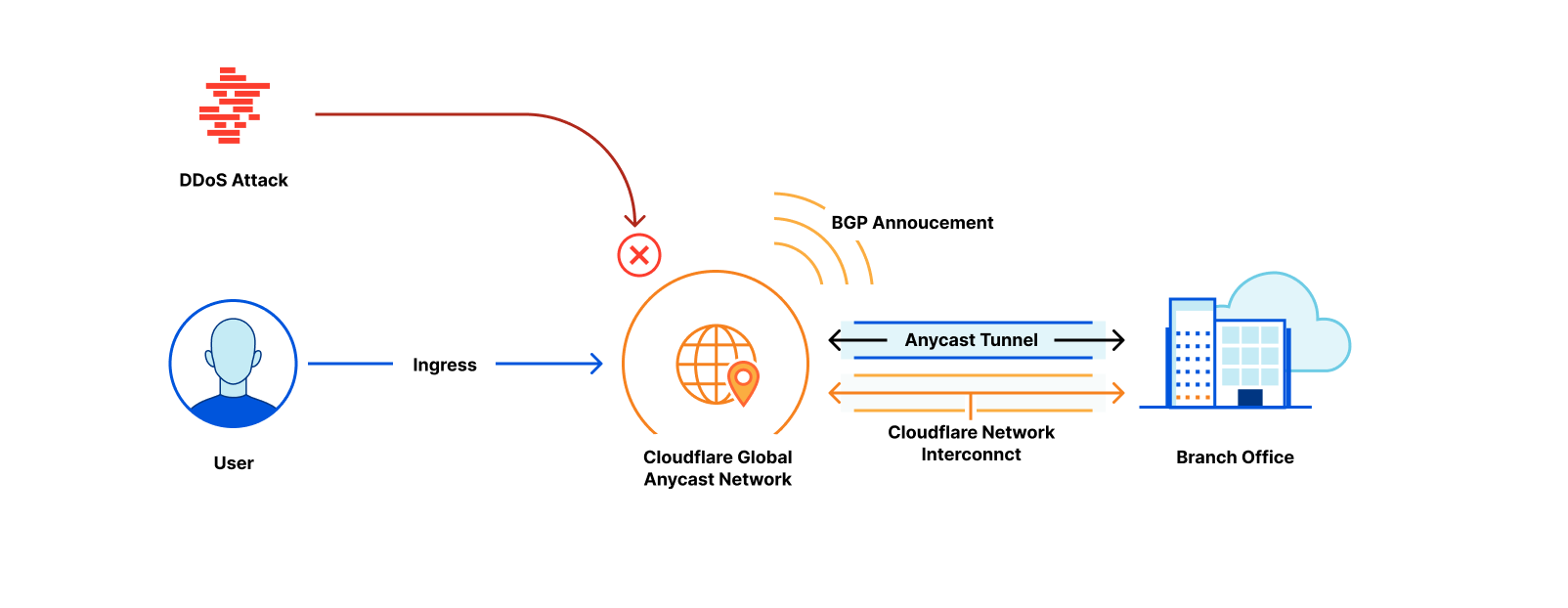
There are two ways to solve this problem. First, if your dedicated source IP is purchased from Cloudflare, you can use the “egress policy by hostname” feature that we announced previously. By contrast, if your dedicated source IP belongs to your organization, or is leased from cloud provider, then we can solve this problem with hostname-based routing, as shown in the figure below:
Here’s how this works:
Force traffic through your dedicated IP. First, you deploy a Cloudflare Tunnel in the network that owns your dedicated IP (for example, your primary VPC in a cloud provider). All traffic you send through this tunnel will exit to the Internet with 203.0.113.9 as its source IP.
Route the banking app to that tunnel. Next, you create a hostname route in your Zero Trust dashboard. This rule tells Cloudflare: “Any traffic destined for bank.example.com must be sent through this specific tunnel.”
Apply your user policies. Finally, in Cloudflare Gateway, you create your granular access rules. A low-priority network policy blocks access to the SNIbank.example.com for everyone. Then, a second, higher-priority policy explicitly allows users in the “finance” group to access the SNIbank.example.com.
Now, when a finance team member accesses the portal, their traffic is correctly routed through the tunnel and arrives with the source IP the bank expects. An employee from any other department is blocked by Gateway before their traffic even enters the tunnel. You’ve enforced a precise, user-based zero trust policy for a third-party service, all by using its public hostname.
Under the hood: how hostname routing works
To build this feature, we needed to solve a classic networking challenge. The routing mechanism for Cloudflare Tunnel is a core part of Cloudflare Gateway, which operates at both Layer 4 (TCP/UDP) and Layer 7 (HTTP/S) of the network stack.
Cloudflare Gateway must make a decision about which Cloudflare Tunnel to send traffic upon receipt of the very first IP packet in the connection. This means the decision must necessarily be made at Layer 4, where Gateway only sees the IP and TCP/UDP headers of a packet. IP and TCP/UDP headers contain the destination IP address, but do not contain destination hostname. The hostname is only found in Layer 7 data (like a TLS SNI field or an HTTP Host header), which isn’t even available until after the Layer 4 connection is already established.
This creates a dilemma: how can we route traffic based on a hostname before we’ve even seen the hostname?
Synthetic IPs to the rescue
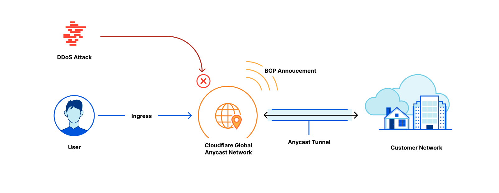
The solution lies in the fact that Cloudflare Gateway also acts as a DNS resolver. This means we see the user’s intent — the DNS query for a hostname — before we see the actual application traffic. We use this foresight to “tag” the traffic using a synthetic IP address.
Let’s walk through the flow:
DNS Query. A user’s device sends a DNS query for canada-payroll-server.acme.local to the Gateway resolver.
Private Resolution. Gateway asks the cloudflared agent running in your private network to resolve the real IP for that hostname. Since cloudflared has access to your internal DNS, it finds the real private IP 10.4.4.4, and sends it back to the Gateway resolver.
Synthetic Response. Here’s the key step. Gateway resolver does not send the real IP (10.4.4.4) back to the user. Instead, it temporarily assigns an initial resolved IP from a reserved Carrier-Grade NAT (CGNAT) address space (e.g., 100.80.10.10) and sends the initial resolved IP back to the user’s device. The initial resolved IP acts as a tag that allows Gateway to identify network traffic destined to canada-payroll-server.acme.local. The initial resolved IP is randomly selected and temporarily assigned from one of the two IP address ranges:
IPv4: 100.80.0.0/16
IPv6: 2606:4700:0cf1:4000::/64
Traffic Arrives. The user’s device sends its application traffic (e.g., an HTTPS request) to the destination IP it received from Gateway resolver: the initial resolved IP 100.80.10.10.
Routing and Rewriting. When Gateway sees an incoming packet destined for 100.80.10.10, it knows this traffic is for canada-payroll-server.acme.local and must be sent through a specific Cloudflare Tunnel. It then rewrites the destination IP on the packet back to the real private destination IP (10.4.4.4) and sends it down the correct tunnel.
The traffic goes down the tunnel and arrives at canada-payroll-server.acme.local at IP (10.4.4.4) and the user is connected to the server without noticing any of these mechanisms. By intercepting the DNS query, we effectively tag the network traffic stream, allowing our Layer 4 router to make the right decision without needing to see Layer 7 data.
Using Gateway Resolver Policies for fine grained control
The routing capabilities we’ve discussed provide simple, powerful ways to connect to private resources. But what happens when your network architecture is more complex? For example, what if your private DNS servers are in one part of your network, but the application itself is in another?
With Cloudflare One, you can solve this by creating policies that separate the path for DNS resolution from the path for application traffic for the very same hostname using Gateway Resolver Policies. This gives you fine-grained control to match complex network topologies.
Let’s walk through a scenario:
Your private DNS resolvers, which can resolve acme.local, are located in your core datacenter, accessible only via tunnel-1.
The webserver for canada-payroll-server.acme.localis hosted in a specific cloud VPC, accessible only via tunnel-2.
Here’s how to configure this split-path routing.
Step 1: Route DNS Queries via tunnel-1
First, we need to tell Cloudflare Gateway how to reach your private DNS server
Create an IP Route: In the Networks > Tunnels area of your Zero Trust dashboard, create a route for the IP address of your private DNS server (e.g., 10.131.0.5/32) and point it to tunnel-1. This ensures any traffic destined for that specific IP goes through the correct tunnel to your datacenter.
Create a Resolver Policy: Go to Gateway -> Resolver Policies and create a new policy with the following logic:
If the query is for the domain acme.local …
Then… resolve it using a designated DNS server with the IP 10.131.0.5.
With these two rules, any DNS lookup for acme.local from a user’s device will be sent through tunnel-1 to your private DNS server for resolution.
Step 2: Route Application Traffic via tunnel-2
Next, we’ll tell Gateway where to send the actual traffic (for example, HTTP/S) for the application.
Create a Hostname Route: In your Zero Trust dashboard, create a hostname route that binds canada-payroll-server.acme.local to tunnel-2.
This rule instructs Gateway that any application traffic (like HTTP, SSH, or any TCP/UDP traffic) for canada-payroll-server.acme.local must be sent through tunnel-2leading to your cloud VPC.
Similarly to a setup without Gateway Resolver Policy, for this to work, you must delete your private network’s subnet (in this case 10.0.0.0/8) and 100.64.0.0/10 from the Split Tunnels Exclude list. You also need to remove .local from the Local Domain Fallback.
Putting It All Together
With these two sets of policies, the “synthetic IP” mechanism handles the complex flow:
A user tries to access canada-payroll-server.acme.local. Their device sends a DNS query to Cloudflare Gateway Resolver.
This DNS query matches a Gateway Resolver Policy, causing Gateway Resolver to forward the DNS query through tunnel-1 to your private DNS server (10.131.0.5).
Your DNS server responds with the server’s actual private destination IP (10.4.4.4).
Gateway receives this IP and generates a “synthetic” initial resolved IP (100.80.10.10) which it sends back to the user’s device.
The user’s device now sends the HTTP/S request to the initial resolved IP (100.80.10.10).
Gateway sees the network traffic destined for the initial resolved IP (100.80.10.10) and, using the mapping, knows it’s for canada-payroll-server.acme.local.
The Hostname Route now matches. Gateway sends the application traffic through tunnel-2 and rewrites its destination IP to the webserver’s actual private IP (10.4.4.4).
The cloudflared agent at the end of tunnel-2 forwards the traffic to the application’s destination IP (10.4.4.4), which is on the same local network.
The user is connected, without noticing that DNS and application traffic have been routed over totally separate private network paths. This approach allows you to support sophisticated split-horizon DNS environments and other advanced network architectures with simple, declarative policies.
What onramps does this support?
Our hostname routing capability is built on the “synthetic IP” (also known as initially resolved IP) mechanism detailed earlier, which requires specific Cloudflare One products to correctly handle both the DNS resolution and the subsequent application traffic. Here’s a breakdown of what’s currently supported for connecting your users (on-ramps) and your private applications (off-ramps).
Connectivity is also possible when users are behind Magic WAN (in active-passive mode) or WARP Connector, but it requires some additional configuration. To ensure traffic is routed correctly, you must update the routing table on your device or router to send traffic for the following destinations through Gateway:
The initially resolved IP ranges: 100.80.0.0/16 (IPv4) and 2606:4700:0cf1:4000::/64 (IPv6).
The private network CIDR where your application is located (e.g., 10.0.0.0/8).
The IP address of your internal DNS resolver.
The Gateway DNS resolver IPs: 172.64.36.1 and 172.64.36.2.
Magic WAN customers will also need to point their DNS resolver to these Gateway resolver IPs and ensure they are running Magic WAN tunnels in active-passive mode: for hostname routing to work, DNS queries and the resulting network traffic must reach Cloudflare over the same Magic WAN tunnel. Currently, hostname routing will not work if your end users are at a site that has more than one Magic WAN tunnel actively transiting traffic at the same time.
Connecting Your Private Network (Off-Ramps)
On the other side of the connection, hostname-based routing is designed specifically for applications connected via Cloudflare Tunnel (cloudflared). This is currently the only supported off-ramp for routing by hostname.
Other traffic off-ramps, while fully supported for IP-based routing, are not yet compatible with this specific hostname-based feature. This includes using Magic WAN, WARP Connector, or WARP-to-WARP connections as the off-ramp to your private network. We are actively working to expand support for more on-ramps and off-ramps in the future, so stay tuned for more updates.
Conclusion
By enabling routing by hostname directly within Cloudflare Tunnel, we’re making security policies simpler, more resilient, and more aligned with how modern applications are built. You no longer need to track ever-changing IP addresses. You can now build precise, per-resource authorization policies for HTTPS applications based on the one thing that should matter: the name of the service you want to connect to. This is a fundamental step in making a zero trust architecture intuitive and achievable for everyone.
This powerful capability is available today, built directly into Cloudflare Tunnel and free for all Cloudflare One customers.
Ready to leave IP Lists behind for good? Get started by exploring our developer documentation to configure your first hostname route. If you’re new to Cloudflare One, you can sign up today and begin securing your applications and networks in minutes.
Cloudflare’s network spans more than 330 cities in over 120 countries, serving over 60 million HTTP requests per second and 39 million DNS queries per second on average. These numbers will continue to grow, and at an accelerating pace, as will Cloudflare’s infrastructure to support them. While we can continue to scale out by deploying more servers, it is also paramount for us to develop and deploy more performant and more efficient servers.
At the heart of each server is the processor (central processing unit, or CPU). Even though many aspects of a server rack can be redesigned to improve the cost to serve a request, CPU remains the biggest lever, as it is typically the primary compute resource in a server, and the primary enabler of new technologies.
The following table is a summary of the specification of the AMD EPYC 7713 CPU in our Gen 11 server against the three CPU candidates, one from each variant of the 4th generation AMD EPYC Processors architecture:
* AMD EPYC 7713 all core boost clock is based on Cloudflare production data, not the official specification from AMD
cf_benchmark
Readers may remember that Cloudflare introduced cf_benchmark when we evaluated Qualcomm’s ARM chips, using it as our first pass benchmark to shortlist AMD’s Rome CPU for our Gen 10 servers and to evaluate our chosen ARM CPU Ampere Altra Max against AWS Graviton 2. Likewise, we ran cf_benchmark against the three candidate CPUs for our 12th Gen servers: AMD EPYC 9654 (Genoa), AMD EPYC 9754 (Bergamo), and AMD EPYC 9684X (Genoa-X). The majority of cf_benchmark workloads are compute bound, and given more cores or higher CPU frequency, they score better. The graph and the table below show the benchmark performance comparison of the three CPU candidates with Genoa 9654 as the baseline, where > 1.00x indicates better performance.
Genoa 9654 (baseline)
Bergamo 9754
Genoa-X 9684X
openssl_pki
1.00x
1.16x
1.01x
openssl_aead
1.00x
1.20x
1.01x
luajit
1.00x
0.86x
1.00x
brotli
1.00x
1.11x
0.98x
gzip
1.00x
0.87x
1.01x
go
1.00x
1.09x
1.00x
Bergamo 9754 with 128 cores scores better in openssl_pki, openssl_aead, brotli, and go benchmark suites, and performs less favorably in luajit and gzip benchmark suites. Genoa-X 9684X (with significantly more L3 cache) doesn’t offer a significant boost in performance for these compute-bound benchmarks.
These benchmarks are representative of some of the common workloads Cloudflare runs, and are useful in identifying software scaling issues, system configuration bottlenecks, and the impact of CPU design choices on workload-specific performance. However, the benchmark suite is not an exhaustive list of all workloads Cloudflare runs in production, and in reality, the workloads included in the benchmark suites are almost certainly not the exclusive workload running on the CPU. In short, though benchmark results can be informative, they do not represent a good indication of production performance when a mix of these workloads run on the same processor.
Performance simulation
To get an early indication of production performance, Cloudflare has an internal performance simulation tool that exercises our software stack to fetch a fixed asset repeatedly. The simulation tool can be configured to fetch a specified fixed-size asset and configured to include or exclude services like WAF or Workers in the request path. Below, we show the simulated performance between the three CPUs for an asset size of 10 KB, where >1.00x indicates better performance.
Milan 7713
Genoa 9654
Bergamo 9754
Genoa-X 9684X
Lab simulation performance multiplier
1.00x
2.20x
1.95x
2.75x
Based on these results, Bergamo 9754, which has the highest core count, but smallest L3 cache per core, is least performant among the three candidates, followed by Genoa 9654. The Genoa-X 9684X with the largest L3 cache per core is the most performant. This data suggests that our software stack is very sensitive to L3 cache size, in addition to core count and CPU frequency. This is interesting and worth a deep dive into a sensitivity analysis of our workload against a few (high level) CPU design points, especially core scaling, frequency scaling, and L2/L3 cache sizes scaling.
Sensitivity analysis
Core sensitivity
Number of cores is the headline specification that practically everyone talks about, and one of the easiest improvements CPU vendors can make to increase performance per socket. The AMD Genoa 9654 has 96 cores, 50% more than the 64 cores available on the AMD Milan 7713 CPUs that we used in our Gen 11 servers. Is more always better? Does Cloudflare’s primary workload scale with core count and effectively utilize all available cores?
The figure and table below shows the result of a core scaling experiment performed on an AMD Genoa 9654 configured with 96 cores, 80 cores, 64 cores, and 48 cores, which was done by incrementally disabling 2x CCD (8 cores/CCD) at each step. The result is GREAT, as Cloudflare’s simulated primary workload scales linearly with core count on AMD Genoa CPUs.
The chart below shows the result of sweeping the TDP of the AMD Genoa 9654 (in power determinism mode) from 240W to 400W. (Note: x-axis step size is not linear).
Cloudflare’s simulated primary workload continues to see incremental performance improvements up to the maximum configurable 400W, albeit at a less favorable perf/watt ratio.
Looking at TDP sensitivity data is a quick and easy way to identify if performance stagnates at some power point, but what does power sensitivity actually measure? There are several factors contributing to CPU power consumption, but let’s focus on one of the primary factors: dynamic power consumption. Dynamic power consumption is approximately CV2f, where C is the switched load capacitance, V is the regulated voltage, and f is the frequency. In modern processors like the AMD Genoa 9654, the CPU dynamically scales its voltage along with frequency, so theoretically, CPU dynamic power is loosely proportional to f3. In other words, measuring TDP sensitivity is measuring the frequency sensitivity of a workload. Does the data agree? Yes!
cTDP
All core boost frequency (GHz)
Perf (rps) / baseline
240
2.47
0.78x
280
2.75
0.87x
320
2.93
0.93x
340
3.13
0.97x
360
3.3
1.00x
380
3.4
1.03x
390
3.465
1.04x
400
3.55
1.05x
Frequency sensitivity
Instead of relying on an indirect measure through the TDP, let’s measure frequency sensitivity directly by sweeping the maximum boost frequency.
At above 3GHz, the data shows that Cloudflare’s primary workload sees roughly 2% incremental improvement for every 0.1GHz all core average frequency increment. We hit the 400W power cap at 3.545GHz. This is notably higher than the typical all core boost frequency that Cloudflare Gen 11 servers with AMD Milan 7713 at 2.7GHz see in production, or at 2.4GHz in our performance simulation, which is amazing!
L3 cache size sensitivity
What about L3 cache size sensitivity? L3 cache size is one of the primary design choices and major differences between the trio of Genoa, Bergamo, and Genoa-X. Genoa 9654 has 4 MB L3/core, Bergamo 9754 has 2 MB L3/core, and Genoa-X has 12 MB L3/core. L3 cache is the last and largest “memory” bank on-chip before having to access memory on DIMMs outside the chip that would take significantly more CPU cycles.
We ran an experiment on the Genoa 9654 to check how performance scales with L3 cache size. L3 cache size per core is reduced through MSR writes (but could also be done using Intel RDT) and L3 cache per core is increased by disabling physical cores in a CCD (which reduces the number of cores sharing the fixed size 32 MB L3 cache per CCD effectively growing the L3 cache per core). Below is the result of the experiment, where >1.00x indicates better performance:
L3 cache size increase vs baseline 4MB per core
0.25x
0.5x
0.75x
1x
1.14x
1.33x
1.60x
2.00x
rps/core / baseline
0.67x
0.78x
0.89x
1.00x
1.08x
1.15x
1.25x
1.31x
L3 cache miss rate per CCD
56.04%
39.15%
30.37%
23.55%
22.39%
19.73%
16.94%
14.28%
Even though the expectation was that the impact of a different L3 cache size gets diminished by the faster DDR5 and larger memory bandwidth, Cloudflare’s simulated primary workload is quite sensitive to L3 cache size. The L3 cache miss rate dropped from 56% with only 1 MB L3 per core, to 14.28% with 8 MB L3/core. Changing the L3 cache size by 25% affects the performance by approximately 11%, and we continue to see performance increase to 2x L3 cache size, though the performance increase starts to diminish when we get to 2x L3 cache per core.
Do we see the same behavior when comparing Genoa 9654, Bergamo 9754 and Genoa-X 9684X? We ran an experiment comparing the impact of L3 cache size, controlling for core count and all core boost frequency, and we also saw significant deltas. Halving the L3 cache size from 4 MB/core to 2 MB/core reduces performance by 24%, roughly matching the experiment above. However, increasing the cache 3x from 4 MB/core to 12 MB/core only increases performance by 25%, less than the indication provided by previous experiments. This is likely because the performance gain we saw on experiment result above could be partially attributed to less cache contention due to reduced number of cores based on how we set up the test. Nevertheless, these are significant deltas!
L3/core
2MB/core
4MB/core
12MB/core
Perf (rps) / baseline
0.76x
1x
1.25x
Putting it all together
The table below summarizes how each factor from sensitivity analysis above contributes to the overall performance gain. There are an additional 6% to 14% of unaccounted performance improvement that are contributed by other factors like larger L2 cache, higher memory bandwidth, and miscellaneous CPU architecture changes that improve IPC.
Milan
7713
Genoa
9654
Bergamo
9754
Genoa-X
9684X
Lab simulation performance multiplier
1x
2.2x
1.95x
2.75x
Performance multiplier due to Core scaling
1x
1.5x
2x
1.5x
Performance multiplier due to Frequency scaling
(*Note: Milan 7713 all core frequency is ~2.4GHz when running simulated workload at 100% CPU utilization)
1x
1.32x
1.21x
1.29x
Performance multiplier due to L3 cache size scaling
1x
1x
0.76x
1.25x
Performance multiplier due to other factors like larger L2 cache, higher memory bandwidth, miscellaneous CPU architecture changes that improve IPC
1x
1.11x
1.06x
1.14x
Performance evaluation in production
How do these CPU candidates perform with real-world traffic and an actual production workload mix? The table below summarizes the performance of the three CPUs in lab simulation and in production. Genoa-X 9684X continues to outperform in production.
In addition, the Gen 12 server equipped with Genoa-X offered outstanding performance but only consumed 1.5x more power per system than our Gen 11 server with Milan 7713. In other words, we see a 63% increase in performance per watt. Genoa-X 9684X provides the best TCO improvement among the 3 options, and was ultimately chosen as the CPU for our Gen 12 server.
Milan 7713
Genoa 9654
Bergamo 9754
Genoa-X 9684X
Lab simulation performance multiplier
1x
2.2x
1.95x
2.75x
Production performance multiplier
1x
2x
2.15x
2.45x
Production performance per watt multiplier
1x
1.33x
1.38x
1.63x
The Gen 12 server with AMD Genoa-X 9684X is the most powerful and the most power efficient server Cloudflare has built to date. It serves as the underlying platform for all the incredible services that Cloudflare offers to our customers globally, and will help power the growth of Cloudflare infrastructure for the next several years with improved cost structure.
Hardware engineers at Cloudflare work closely with our infrastructure engineering partners and externally with our vendors to design and develop world-class servers to best serve our customers.
Come join us at Cloudflare to help build a better Internet!
In the dynamic evolution of AI and cloud computing, the deployment of efficient and reliable hardware is critical. As we roll out our Gen 12 hardware across hundreds of cities worldwide, the challenge of maintaining optimal thermal performance becomes essential. This blog post provides a deep dive into the robust thermal design that supports our newest Gen 12 server hardware, ensuring it remains reliable, efficient, and cool (pun very much intended).
The importance of thermal design for hardware electronics
Generally speaking, a server has five core resources: CPU (computing power), RAM (short term memory), SSD (long term storage), NIC (Network Interface Controller, connectivity beyond the server), and GPU (for AI/ML computations). Each of these components can withstand different temperature limits based on their design, materials, location within the server, and most importantly, the power they are designed to work at. This final criteria is known as thermal design power (TDP).
The reason why TDP is so important is closely related to the first law of thermodynamics, which states that energy cannot be created or destroyed, only transformed. In semiconductors, electrical energy is converted into heat, and TDP measures the maximum heat output that needs to be managed to ensure proper functioning.
Back in December 2023, we talked about our decision to move to a 2U form factor, doubling the height of the server chassis to optimize rack density and increase cooling capacity. In this post, we want to share more details on how this additional space is being used to improve performance and reliability supporting up to three times more total system power.
Standardization
In order to support our multi-vendor strategy that mitigates supply chain risks ensuring continuity for our infrastructure, we introduced our own thermal specification to standardize thermal design and system performance. At Cloudflare, we find significant value in building customized hardware optimized for our unique workloads and applications, and we are very fortunate to partner with great hardware vendors who understand and support this vision. However, partnering with multiple vendors can introduce design variables that Cloudflare then controls for consistency within a hardware generation. Some of the most relevant requirements we include in our thermal specification are:
Ambient conditions: Given our globally distributed footprint with presence in over 330 cities, environmental conditions can vary significantly. Hence, servers in our fleet can experience a wide range of temperatures, typically ranging between 28 to 35°C. Therefore, our systems are designed and validated to operate with no issue over temperature ranges from 5 to 40°C (following the ASHRAE A3 definition).
Thermal margins: Cloudflare designs with clear requirements for temperature limits on different operating conditions, simulating peak stress, average workloads, and idle conditions. This allows Cloudflare to validate that the system won’t experience thermal throttling, which is a power management control mechanism used to protect electronics from high temperatures.
Fan failure support to increase system reliability: This new generation of servers is 100% air cooled. As such, the algorithm that controls fan speed based on critical component temperature needs to be optimized to support continuous operation over the server life cycle. Even though fans are designed with a high (up to seven years) mean time between failure (MTBF), we know fans can and do fail. Losing a server’s worth of capacity due to thermal risks caused by a single fan failure is expensive. Cloudflare requires the server to continue to operate with no issue even in the event of one fan failure. Each Gen 12 server contains four axial fans providing the extra cooling capacity to prevent failures.
Maximum power used to cool the system: Because our goal is to serve more Internet traffic using less power, we aim to ensure the hardware we deploy is using power efficiently. Great thermal management must consider the overall cost of cooling relative to the total system power input. It is inefficient to burn power consumption on cooling instead of compute. Thermal solutions should look at the hardware architecture holistically and implement mechanical modifications to the system design in order to optimize airflow and cooling capacity before considering increasing fan speed, as fan power consumption proportionally scales to the cube of its rotational speed. (For example, running the fans at twice (2x) the rotational speed would consume 8x more power,)
System layout
Placing each component strategically within the server will also influence the thermal performance of the system. For this generation of servers, we made several internal layout decisions, where the final component placement takes into consideration optimal airflow patterns, preventing pre-heated air from affecting equipment in the rear end of the chassis.
Bigger and more powerful fans were selected in order to take advantage of the additional volume available in a 2U form factor. Growing from 40 to 80 millimeters, a single fan can provide up to four times more airflow. Hence, bigger fans can run at slower speeds to provide the required airflow to cool down the same components, significantly improving power efficiency.
The Extended Volume Air Cooled (EVAC) heatsink was optimized for Gen 12 hardware, and is designed with increased surface area to maximize heat transfer. It uses heatpipes to move the heat effectively away from the CPU to the extended fin region that sits immediately in front of the fans as shown in the picture below.
EVAC heatsink installed in one of our Gen 12 servers. The extended fin region sits right in front of the axial fans. (Photo courtesy of vendor.)
The combination of optimized heatsink design and selection of high-performing fans is expected to significantly reduce the power used for cooling the system. These savings will vary depending on ambient conditions and system stress, but under a typical stress scenario at 25°C ambient temperature, power savings could be as much as 50%.
Additionally, we ensured that the critical components in the rear section of the system, such as the NIC and DC-SCM, were positioned away from the heatsink to promote the use of cooler available air within the system. Learning from past experience, the NIC temperature is monitored by the Baseboard Management Controller (BMC), which provides remote access to the server for administrative tasks and monitoring health metrics. Because the NIC has a built-in feature to protect itself from overheating by going into standby mode when the chip temperature reaches critical limits, it is important to provide air at the lowest possible temperature. As a reference, the temperature of the air right behind the CPU heatsink can reach 70°C or higher, whereas behind the memory banks, it would reach about 55°C under the same circumstances. The image below shows the internal placement of the most relevant components considered while building the thermal solution.
Using air as cold as possible to cool down any component will increase overall system reliability, preventing potential thermal issues and unplanned system shutdowns. That’s why our fan algorithm uses every thermal sensor available to ensure thermal health while using the minimum possible amount of energy.
Components inside the compute server from one of our vendors, viewed from the rear of the server. (Illustration courtesy of vendor.)
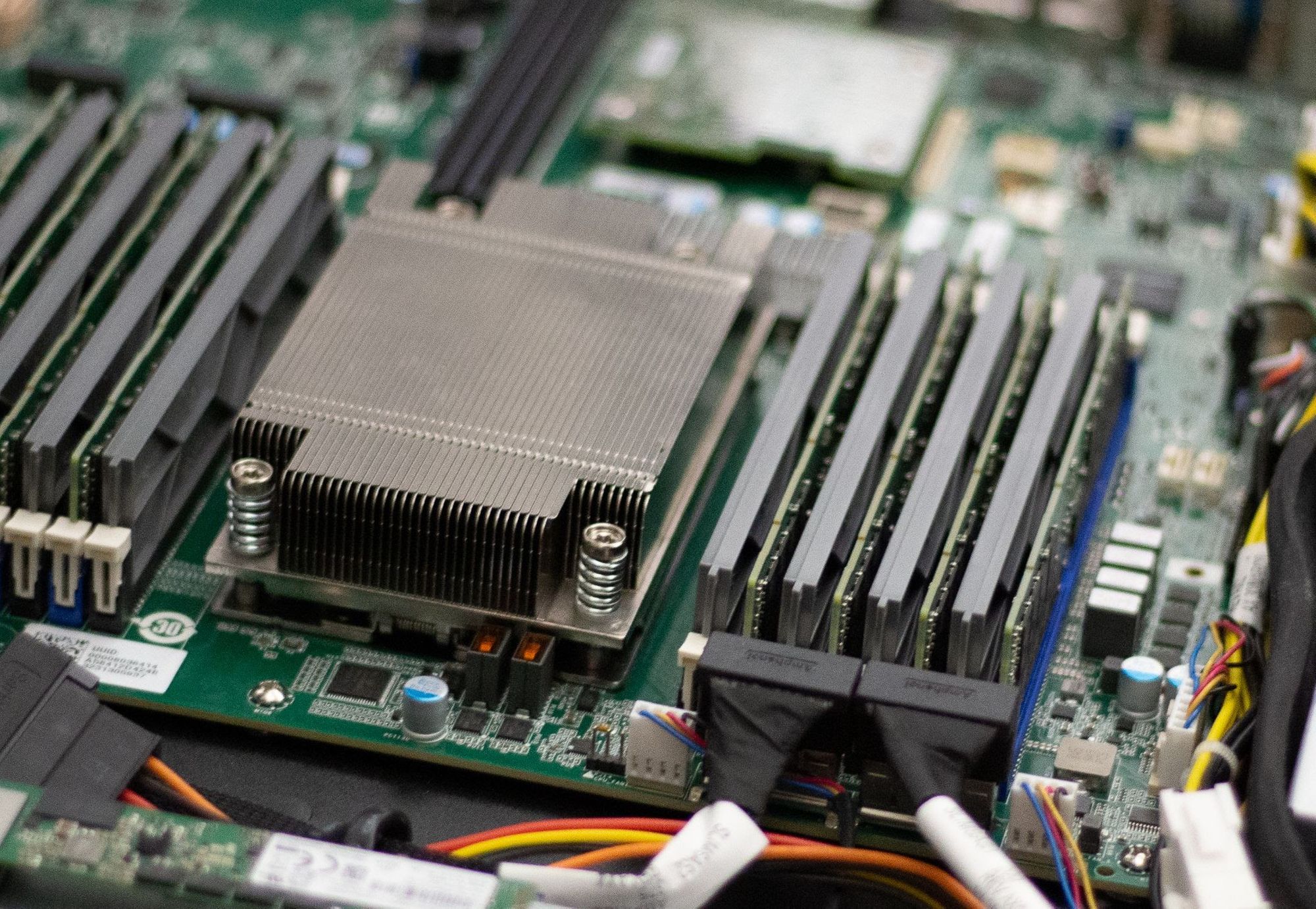
1️. Host Processor Module (HPM)
8. Power Distribution Board (PDB)
2️. DIMMs (x12)
9. GPUs (up to 2)
3️. CPU (under CPU heatsink)
10. GPU riser card
4. CPU heatsink
11. GPU riser cage
5. System fans (x4: 80mm, dual rotor)
12. Power Supply Units, PSUs (x2)
6. Bracket with power button and intrusion switch
13. DC-SCM 2.0 module
7. E1.S SSD
14. OCP 3.0 module
Making hardware flexible
With the same thought process of optimizing system layout, we decided to use a PCIe riser above the Power Supply Units (PSUs), enabling the support of up to 2x single wide GPU add-in cards. Once again, the combination of high-performing fans with strategic system architecture gave us the capability to add up to 400W to the original power envelope and incorporate accelerators used in our new and recently announced AI and ML features.
Hardware lead times are typically long, certainly when compared to software development. Therefore, a reliable strategy for hardware flexibility is imperative in this rapidly changing environment for specialized computing. When we started evaluating Gen 12 hardware architecture and early concept design, we didn’t know for sure we would be needing to implement GPUs for this generation, let alone how many or which type. However, highly efficient design and intentional due diligence analyzing hypothetical use cases help ensure flexibility and scalability of our thermal solution, supporting new requirements from our product teams, and ultimately providing the best solutions to our customers.
Rack-integrated solutions
We are also increasing the volume of integrated racks shipped to our global colocation facilities. Due to the expected increase in rack shipments, it is now more important that we also increase the corresponding mechanical and thermal test coverage from system level (L10) to rack level (L11).
Since our servers don’t use the full depth of a standard rack in order to leave room for cable management and Power Distribution Units (PDUs), there is another fluid mechanics factor that we need to consider to improve our holistic solution.
We design our hardware based on one of the most typical data center architectures, which have alternating cold and hot aisles. Fans at the front of the server pull in cold air from the corresponding aisle, the air then flows through the server, cooling down the internal components and the hot air is exhausted into the adjacent aisle, as illustrated in the diagram below.
A conventional air-flow diagram of a standard server where the cold air enters from the front of the server and hot air leaves through the rear side of the system.
In fluid dynamics, the minimum effort principle will drive fluids (air in this case) to move where there is less resistance — i.e. wherever it takes less energy to get from point A to point B. With the help of fans forcing air to flow inside the server and pushing it through the rear, the more crowded systems will naturally get less air than those with more space where the air can move around. Since we need more airflow to pass through the systems with higher power demands, we’ve also ensured that the rack configuration keeps these systems in the bottom of the rack where air tends to be at a lower temperature. Remember that heat rises, so even within the cold aisle, there can be a small but important temperature difference between the bottom and the top section of the rack. It is our duty as hardware engineers to use thermodynamics in our favor.
Conclusion
Our new generation of hardware is live in our data centers and it represents a significant leap forward in our efficiency, reliability, and sustainability commitments. Combining optimal heat sink design, thoughtful fan selection, and meticulous system layout and hardware architecture, we are confident that these new servers will operate smoothly in our global network with diverse environmental conditions, maintaining optimal performance of our Connectivity Cloud.
Come join us at Cloudflare to help deliver a better Internet!
Cloudflare is thrilled to announce the general deployment of our next generation of servers — Gen 12 powered by AMD EPYC 9684X (code name “Genoa-X”) processors. This next generation focuses on delivering exceptional performance across all Cloudflare services, enhanced support for AI/ML workloads, significant strides in power efficiency, and improved security features.
Here are some key performance indicators and feature improvements that this generation delivers as compared to the prior generation:
Beginning with performance, with close engineering collaboration between Cloudflare and AMD on optimization, Gen 12 servers can serve more than twice as many requests per second (RPS) as Gen 11 servers, resulting in lower Cloudflare infrastructure build-out costs.
Next, our power efficiency has improved significantly, by more than 60% in RPS per watt as compared to the prior generation. As Cloudflare continues to expand our infrastructure footprint, the improved efficiency helps reduce Cloudflare’s operational expenditure and carbon footprint as a percentage of our fleet size.
Third, in response to the growing demand for AI capabilities, we’ve updated the thermal-mechanical design of our Gen 12 server to support more powerful GPUs. This aligns with the Workers AI objective to support larger large language models and increase throughput for smaller models. This enhancement underscores our ongoing commitment to advancing AI inference capabilities
Fourth, to underscore our security-first position as a company, we’ve integrated hardware root of trust (HRoT) capabilities to ensure the integrity of boot firmware and board management controller firmware. Continuing to embrace open standards, the baseboard management and security controller (Data Center Secure Control Module or OCP DC-SCM) that we’ve designed into our systems is modular and vendor-agnostic, enabling a unified openBMC image, quicker prototyping, and allowing for reuse.
Finally, given the increasing importance of supply assurance and reliability in infrastructure deployments, our approach includes a robust multi-vendor strategy to mitigate supply chain risks, ensuring continuity and resiliency of our infrastructure deployment.
Cloudflare is dedicated to constantly improving our server fleet, empowering businesses worldwide with enhanced performance, efficiency, and security.
Gen 12 Servers
Let’s take a closer look at our Gen 12 server. The server is powered by a 4th generation AMD EPYC Processor, paired with 384 GB of DDR5 RAM, 16 TB of NVMe storage, a dual-port 25 GbE NIC, and two 800 watt power supply units.
During the design phase, we conducted an extensive survey of the CPU landscape. These options offer valuable choices as we consider how to shape the future of Cloudflare’s server technology to match the needs of our customers. We evaluated many candidates in the lab, and short-listed three standout CPU candidates from the 4th generation AMD EPYC Processor lineup: Genoa 9654, Bergamo 9754, and Genoa-X 9684X for production evaluation. The table below summarizes the differences in specifications of the short-listed candidates for Gen 12 servers against the AMD EPYC 7713 used in our Gen 11 servers. Notably, all three candidates offer significant increase in core count and marked increase in all core boost clock frequency.
*Note: AMD EPYC 7713 all core boost clock frequency of 2.7 GHz is not an official specification of the CPU but based on data collected at Cloudflare production fleet.
During production evaluation, the configuration of all three CPUs were optimized to the best of our knowledge, including thermal design power (TDP) configured to 400W for maximum performance. The servers are set up to run the same processes and services like any other server we have in production, which makes for a great side-by-side comparison.
Milan 7713
Genoa 9654
Bergamo 9754
Genoa-X 9684X
Production performance (request per second) multiplier
1x
2x
2.15x
2.45x
Production efficiency (request per second per watt) multiplier
1x
1.33x
1.38x
1.63x
AMD EPYC Genoa-X in Cloudflare Gen 12 server
Each of these CPUs outperforms the previous generation of processors by at least 2x. AMD EPYC 9684X Genoa-X with 3D V-cache technology gave us the greatest performance improvement, at 2.45x, when compared against our Gen 11 servers with AMD EPYC 7713 Milan.
Comparing the performance between Genoa-X 9684X and Genoa 9654, we see a ~22.5% performance delta. The primary difference between the two CPUs is the amount of L3 cache available on the CPU. Genoa-X 9684X has 1152 MB of L3 cache, which is three times the Genoa 9654 with 384 MB of L3 cache. Cloudflare workloads benefit from more low level cache being accessible and avoid the much larger latency penalty associated with fetching data from memory.
Genoa-X 9684X CPU delivered ~22.5% improved performance consuming the same amount of 400W power compared to Genoa 9654. The 3x larger L3 cache does consume additional power, but only at the expense of sacrificing 3% of highest achievable all core boost frequency on Genoa-X 9684X, a favorable trade-off for Cloudflare workloads.
More importantly, Genoa-X 9684X CPU delivered 145% performance improvement with only 50% system power increase, offering a 63% power efficiency improvement that will help drive down operational expenditure tremendously. It is important to note that even though a big portion of the power efficiency is due to the CPU, it needs to be paired with optimal thermal-mechanical design to realize the full benefit. Earlier last year, we made the thermal-mechanical design choice to double the height of the server chassis to optimize rack density and cooling efficiency across our global data centers. We estimated that moving from 1U to 2U would reduce fan power by 150W, which would decrease system power from 750 watts to 600 watts. Guess what? We were right — a Gen 12 server consumes 600 watts per system at a typical ambient temperature of 25°C.
While high performance often comes at a higher price, fortunately AMD EPYC 9684X offer an excellent balance between cost and capability. A server designed with this CPU provides top-tier performance without necessitating a huge financial outlay, resulting in a good Total Cost of Ownership improvement for Cloudflare.
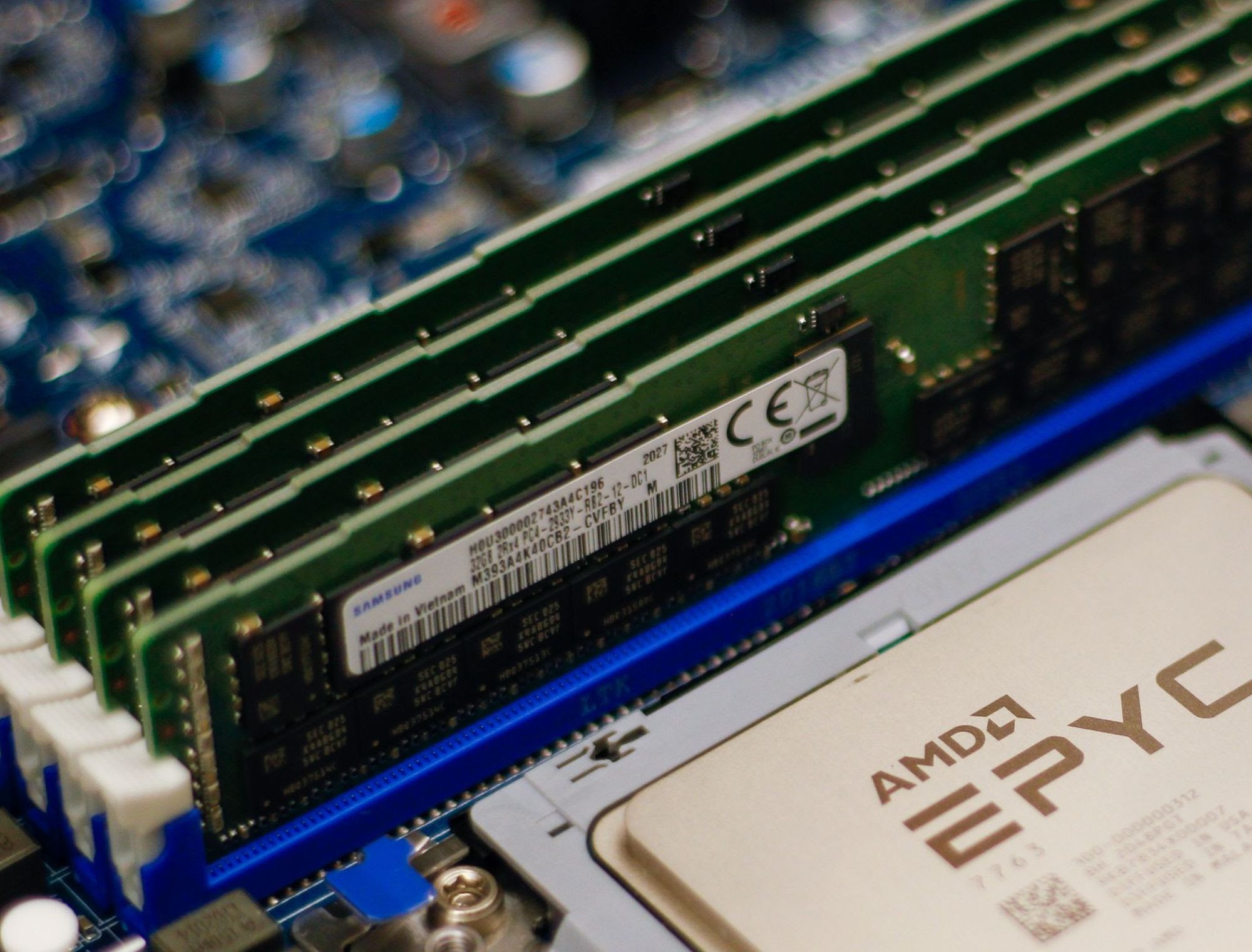
Memory
AMD Genoa-X CPU supports twelve memory channels of DDR5 RAM up to 4800 mega transfers per second (MT/s) and per socket Memory Bandwidth of 460.8 GB/s. The twelve channels are fully utilized with 32 GB ECC 2Rx8 DDR5 RDIMM with one DIMM per channel configuration for a combined total memory capacity of 384 GB.
Choosing the optimal memory capacity is a balancing act, as maintaining an optimal memory-to-core ratio is important to make sure CPU capacity or memory capacity is not wasted. Some may remember that our Gen 11 servers with 64 core AMD EPYC 7713 CPUs are also configured with 384 GB of memory, which is about 6 GB per core. So why did we choose to configure our Gen 12 servers with 384 GB of memory when the core count is growing to 96 cores? Great question! A lot of memory optimization work has happened since we introduced Gen 11, including some that we blogged about, like Bot Management code optimization and our transition to highly efficient Pingora. In addition, each service has a memory allocation that is sized for optimal performance. The per-service memory allocation is programmed and monitored utilizing Linux control group resource management features. When sizing memory capacity for Gen 12, we consulted with the team who monitor resource allocation and surveyed memory utilization metrics collected from our fleet. The result of the analysis is that the optimal memory-to-core ratio is 4 GB per CPU core, or 384 GB total memory capacity. This configuration is validated in production. We chose dual rank memory modules over single rank memory modules because they have higher memory throughput, which improves server performance (read more about memory module organization and its effect on memory bandwidth).
The table below shows the result of running the Intel Memory Latency Checker (MLC) tool to measure peak memory bandwidth for the system and to compare memory throughput between 12 channels of dual-rank (2Rx8) 32 GB DIMM and 12 channels of single rank (1Rx4) 32 GB DIMM. Dual rank DIMMs have slightly higher (1.8%) read memory bandwidth, but noticeably higher write bandwidth. As write ratios increased from 25% to 50%, the memory throughput delta increased by 10%.
Benchmark
Dual rank advantage over single rank
Intel MLC ALL Reads
101.8%
Intel MLC 3:1 Reads-Writes
107.7%
Intel MLC 2:1 Reads-Writes
112.9%
Intel MLC 1:1 Reads-Writes
117.8%
Intel MLC Stream-triad like
108.6%
The table below shows the result of running the AMD STREAM benchmark to measure sustainable main memory bandwidth in MB/s and the corresponding computation rate for simple vector kernels. In all 4 types of vector kernels, dual rank DIMMs provide a noticeable advantage over single rank DIMMs.
Benchmark
Dual rank advantage over single rank
Stream Copy
115.44%
Stream Scale
111.22%
Stream Add
109.06%
Stream Triad
107.70%
Storage
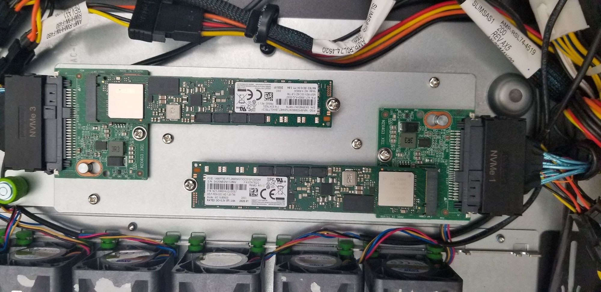
Cloudflare’s Gen X server and Gen 11 server support M.2 form factor drives. We liked the M.2 form factor mainly because it was compact. The M.2 specification was introduced in 2012, but today, the connector system is dated and the industry has concerns about its ability to maintain signal integrity with the high speed signal specified by PCIe 5.0 and PCIe 6.0 specifications. The 8.25W thermal limit of the M.2 form factor also limits the number of flash dies that can be fitted, which limits the maximum supported capacity per drive. To address these concerns, the industry has introduced the E1.S specification and is transitioning from the M.2 form factor to the E1.S form factor.
In Gen 12, we are making the change to the EDSFF E1 form factor, more specifically the E1.S 15mm. E1.S 15mm, though still in a compact form factor, provides more space to fit more flash dies for larger capacity support. The form factor also has better cooling design to support more than 25W of sustained power.
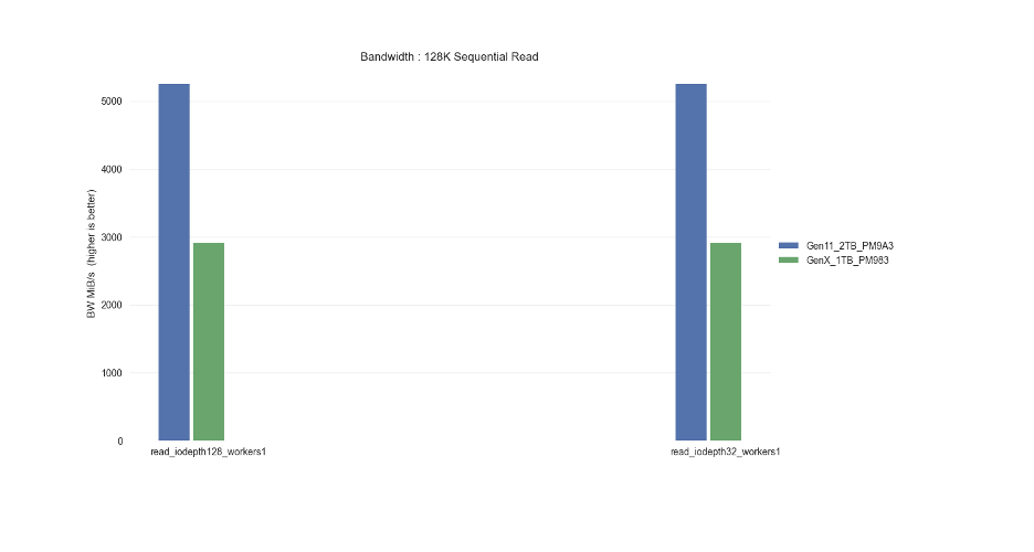
While the AMD Genoa-X CPU supports 128 PCIe 5.0 lanes, we continue to use NVMe devices with PCIe Gen 4.0 x4 lanes, as PCIe Gen 4.0 throughput is sufficient to meet drive bandwidth requirements and keep server design costs optimal. The server is equipped with two 8 TB NVMe drives for a total of 16 TB available storage. We opted for two 8 TB drives instead of four 4 TB drives because the dual 8 TB configuration already provides sufficient I/O bandwidth for all Cloudflare workloads that run on each server.
Sequential Read (MB/s) :
6,700
Sequential Write (MB/s) :
4,000
Random Read IOPS:
1,000,000
Random Write IOPS:
200,000
Endurance
1 DWPD
PCIe GEN4 x4 lane throughput
7880 MB/s
Storage devices performance specification
Network
Cloudflare servers and top-of-rack (ToR) network equipment operate at 25 GbE speeds. In Gen 12, we utilized a DC-MHS motherboard-inspired design, and upgraded from an OCP 2.0 form factor to an OCP 3.0 form factor, which provides tool-less serviceability of the NIC. The OCP 3.0 form factor also occupies less space in the 2U server compared to PCIe-attached NICs, which improves airflow and frees up space for other application-specific PCIe cards, such as GPUs.
Cloudflare has been using the Mellanox CX4-Lx EN dual port 25 GbE NIC since our Gen 9 servers in 2018. Even though the NIC has served us well over the years, we are single sourced. During the pandemic, we were faced with supply constraints and extremely long lead times. The team scrambled to qualify the Broadcom M225P dual port 25 GbE NIC as our second-sourced NIC in 2022, ensuring we could continue to turn up servers to serve customer demand. With the lessons learned from single-sourcing the Gen 11 NIC, we are now dual-sourcing and have chosen the Intel Ethernet Network Adapter E810 and NVIDIA Mellanox ConnectX-6 Lx to support Gen 12. These two NICs are compliant with the OCP 3.0 specification and offer more MSI-X queues that can then be mapped to the increased core count on the AMD EPYC 9684X. The Intel Ethernet Network Adapter comes with an additional advantage, offering full Generic Segmentation Offload (GSO) support including VLAN-tagged encapsulated traffic, whereast many vendors either only support Partial GSO or do not support it at all today. With Full GSO support, the kernel spent noticeably less time in softirq segmenting packets, and servers with Intel E810 NICs are processing approximately 2% more requests per second.
Improved security with DC-SCM: Project Argus
DC-SCM in Gen 12 server (Project Argus)
Gen 12 servers are integrated with Project Argus, one of the industry first implementations of Data Center Secure Control Module 2.0 (DC-SCM 2.0). DC-SCM 2.0 decouples server management and security functions away from the motherboard. The baseboard management controller (BMC), hardware root of trust (HRoT), trusted platform module (TPM), and dual BMC/BIOS flash chips are all installed on the DC-SCM.
On our Gen X and Gen 11 server, Cloudflare moved our secure boot trust anchor from the system Basic Input/Output System (BIOS) or the Unified Extensible Firmware Interface (UEFI) firmware to hardware-rooted boot integrity — AMD’s implementation of Platform Secure Boot (PSB) or Ampere’s implementation of Single Domain Secure Boot. These solutions helped secure Cloudflare infrastructure from BIOS / UEFI firmware attacks. However, we are still vulnerable to out-of-band attacks through compromising the BMC firmware. BMC is a microcontroller that provides out-of-band monitoring and management capabilities for the system. When compromised, attackers can read processor console logs accessible by BMC and control server power states for example. On Gen 12, the HRoT on the DC-SCM serves as the trust store of cryptographic keys and is responsible to authenticate the BIOS/UEFI firmware (independent of CPU vendor) and the BMC firmware for secure boot process.
In addition, on the DC-SCM, there are additional flash storage devices to enable storing back-up BIOS/UEFI firmware and BMC firmware to allow rapid recovery when a corrupted or malicious firmware is programmed, and to be resilient to flash chip failure due to aging.
These updates make our Gen 12 server more secure and more resilient to firmware attacks.
Power
A Gen 12 server consumes 600 watts at a typical ambient temperature of 25°C. Even though this is a 50% increase from the 400 watts consumed by the Gen 11 server, as mentioned above in the CPU section, this is a relatively small price to pay for a 145% increase in performance. We’ve paired the server up with dual 800W common redundant power supplies (CRPS) with 80 PLUS Titanium grade efficiency. Both power supply units (PSU) operate actively with distributed power and current. The units are hot-pluggable, allowing the server to operate with redundancy and maximize uptime.
80 PLUS is a PSU efficiency certification program. The Titanium grade efficiency PSU is 2% more efficient than the Platinum grade efficiency PSU between typical operating load of 25% to 50%. 2% may not sound like a lot, but considering the size of Cloudflare fleet with servers deployed worldwide, 2% savings over the lifetime of all Gen 12 deployment is a reduction of more than 7 GWh, equivalent to carbon sequestered by more than 3400 acres of U.S. forests in one year. This upgrade also means our Gen 12 server complies with EU Lot9 requirements and can be deployed in the EU region.
80 PLUS certification
10%
20%
50%
100%
80 PLUS Platinum
–
92%
94%
90%
80 PLUS Titanium
90%
94%
96%
91%
Drop-in GPU support
Demand for machine learning and AI workloads exploded in 2023, and Cloudflare introduced Workers AI to serve the needs of our customers. Cloudflare retrofitted or deployed GPUs worldwide in a portion of our Gen 11 server fleet to support the growth of Workers AI. Our Gen 12 server is also designed to accommodate the addition of more powerful GPUs. This gives Cloudflare the flexibility to support Workers AI in all regions of the world, and to strategically place GPUs in regions to reduce inference latency for our customers. With this design, the server can run Cloudflare’s full software stack. During times when GPUs see lower utilization, the server continues to serve general web requests and remains productive.
The electrical design of the motherboard is designed to support up to two PCIe add-in cards and the power distribution board is sized to support an additional 400W of power. The mechanics are sized to support either a single FHFL (full height, full length) double width GPU PCIe card, or two FHFL single width GPU PCIe cards. The thermal solution including the component placement, fans, and air duct design are sized to support adding GPUs with TDP up to 400W.
Looking to the future
Gen 12 Servers are currently deployed and live in multiple Cloudflare data centers worldwide, and already process millions of requests per second. Cloudflare’s EPYC journey has not ended — the 5th-gen AMD EPYC CPUs (code name “Turin”) are already available for testing, and we are very excited to start the architecture planning and design discussion for the Gen 13 server. Come join us at Cloudflare to help build a better Internet!
Infrastructure planning for a network serving more than 81 million requests at peak and which is globally distributed across more than 330 cities in 120+ countries is complex. The capacity planning team at Cloudflare ensures there is enough capacity in place all over the world so that our customers have one less thing to worry about – our infrastructure, which should just work. Through our processes, the team puts careful consideration into “what-ifs”. What if something unexpected happens and one of our data centers fails? What if one of our largest customers triples, or quadruples their request count? Across a gamut of scenarios like these, the team works to understand where traffic will be served from and how the Cloudflare customer experience may change.
This blog post gives a look behind the curtain of how these scenarios are modeled at Cloudflare, and why it’s so critical for our customers.
Scenario planning and our customers
Cloudflare customers rely on the data centers that Cloudflare has deployed all over the world, placing us within 50 ms of approximately 95% of the Internet-connected population globally. But round-trip time to our end users means little if those data centers don’t have the capacity to serve requests. Cloudflare has invested deeply into systems that are working around the clock to optimize the requests flowing through our network because we know that failures happen all the time: the Internet can be a volatile place. See our blog post from August 2024 on how we handle this volatility in real time on our backbone, and our blog post from late 2023 about how another system, Traffic Manager, actively works in and between data centers, moving traffic to optimize the customer experience around constraints in our data centers. Both of these systems do a fantastic job in real time, but there is still a gap — what about over the long term?
Most of the volatility that the above systems are built to manage is resolved within shorter time scales than which we build plans for. (There are, of course, some failures that are exceptions.) Most scenarios we model still need to take into account the state of our data centers in the future, as well as what actions systems like Traffic Manager will take during those periods. But before getting into those constraints, it’s important to note how capacity planning measures things: in units of CPU Time, defined as the time that each request takes in the CPU. This is done for the same reasons that Traffic Manager uses CPU Time, in that it enables the team to 1) use a common unit across different types of customer workloads and 2) speak a common language with other teams and systems (like Traffic Manager). The same reasoning the Traffic Manager team cited in their own blog post is equally applicable for capacity planning:
…using requests per second as a metric isn’t accurate enough when actually moving traffic. The reason for this is that different customers have different resource costs to our service; a website served mainly from cache with the WAF deactivated is much cheaper CPU wise than a site with all WAF rules enabled and caching disabled. So we record the time that each request takes in the CPU. We can then aggregate the CPU time across each plan to find the CPU time usage per plan. We record the CPU time in ms, and take a per second value, resulting in a unit of milliseconds per second.
This is important for customers for the same reason that the Traffic Manager team cited in their blog post as well: we can correlate CPU time to performance, specifically latency.
Now that we know our unit of measurement is CPU time, we need to set up our models with the new constraints associated with the change that we’re trying to model. Specifically, there are a subset of constraints that we are particularly interested in because we know that they have the ability to impact our customers by impacting the availability of CPU in a data center. These are split into two main inputs in our models: Supply and Demand. We can think of these as “what-if” questions, such as the following examples:
Demand what-ifs
What if a new customer onboards to Cloudflare with a significant volume of requests and/or bytes?
What if an existing customer increased its volume of requests and/or bytes by some multiplier (i.e. 2x, 3x, nx), at peak, for the next three months?
What if the growth rate, in number of requests and bytes, of all of our data centers worldwide increased from X to Y two months from now, indefinitely?
What if the growth rate, in number of requests and bytes, of data center facility A increased from X to Y one month from now?
What if traffic egressing from Cloudflare to a last-mile network shifted from one location (such as Boston) to another (such as New York City) next week?
Supply what-ifs
What if data center facility A lost some or all of its available servers two months from now?
What if we added X servers to data center facility A today?
For any one of these, or a combination of them, in our model’s output, we aim to provide answers to the following:
What will the overall capacity picture look like over time?
Where will the traffic go?
How will this impact our costs?
Will we need to deploy additional servers to handle the increased load?
Given these sets of questions and outputs, manually creating a model to answer each of these questions, or a combination of these questions, quickly becomes an operational burden for any team. This is what led us to launch “Scenario Planner”.
Scenario Planner
In August 2024, the infrastructure team finished building “Scenario Planner”, a system that enables anyone at Cloudflare to simulate “what-ifs”. This provides our team the opportunity to quickly model hypothetical changes to our demand and supply metrics across time and in any of Cloudflare’s data centers. The core functionality of the system has to do with the same questions we need to answer in the manual models discussed above. After we enter the changes we want to model, Scenario Planner converts from units that are commonly associated with each question to our common unit of measurement: CPU Time. These inputs are then used to model the updated capacity across all of our data centers, including how demand may be distributed in cases where capacity constraints may start impacting performance in a particular location. As we know, if that happens then it triggers Traffic Manager to serve some portion of those requests from a nearby location to minimize impact on customers and user experience.
Updated demand questions with inputs
Question: What if a new customer onboards to Cloudflare with a significant volume of requests?
Input: The new customer’s expected volume, geographic distribution, and timeframe of requests, converted to a count of virtual CPUs
Calculation(s): Scenario Planner converts from server count to CPU Time, and distributes the new demand across the regions selected according to the aggregate distribution of all customer usage.
Question: What if an existing customer increased its volume of requests and/or bytes by some multiplier (i.e. 2x, 3x, nx), at peak, for the next three months?
Input: Select the customer name, the multiplier, and the timeframe
Calculation(s): Scenario Planner already has how the selected customer’s traffic is distributed across all data centers globally, so this involves simply multiplying that value by the multiplier selected by the user
Question: What if the growth rate, in number of requests and bytes, of all of our data centers worldwide increased from X to Y two months from now, indefinitely?
Input: Enter a new global growth rate and timeframe
Calculation(s): Scenario Planner distributes this growth across all data centers globally according to their current growth rate. In other words, the global growth is an aggregation of all individual data center’s growth rates, and to apply a new “Global” growth rate, the system scales up each of the individual data center’s growth rates commensurate with the current distribution of growth.
Question: What if the growth rate, in number of requests and bytes, of data center facility A increased from X to Y one month from now?
Input: Select a data center facility, enter a new growth rate for that data center and the timeframe to apply that change across.
Calculation(s): Scenario Planner passes the new growth rate for the data center to the backend simulator, across the timeline specified by the user
Updated supply questions with inputs
Question: What if data center facility A lost some or all of its available servers two months from now?
Input: Select a data center, and enter the number of servers to remove, or select to remove all servers in that location, as well as the timeframe for when those servers will not be available
Calculation(s): Scenario Planner converts the server count entered (including all servers in a given location) to CPU Time before passing to the backend
Question: What if we added X servers to data center facility A today?
Input: Select a data center, and enter the number of servers to add, as well as the timeline for when those servers will first go live
Calculation(s): Scenario Planner converts the server count entered (including all servers in a given location) to CPU Time before passing to the backend
We made it simple for internal users to understand the impact of those changes because Scenario Planner outputs the same views that everyone who has seen our heatmaps and visual representations of our capacity status is familiar with. There are two main outputs the system provides: a heatmap and an “Expected Failovers” view. Below, we explore what these are, with some examples.
Heatmap
Capacity planning evaluates its success on its ability to predict demand: we generally produce a weekly, monthly, and quarterly forecast of 12 months to three years worth of demand, and nearly all of our infrastructure decisions are based on the output of this forecast. Scenario Planner provides a view of the results of those forecasts that are implemented via a heatmap: it shows our current state, as well as future planned server additions that are scheduled based on the forecast.
Here is an example of our heatmap, showing some of our largest data centers in Eastern North America (ENAM). Ashburn is showing as yellow, briefly, because our capacity planning threshold for adding more server capacity to our data centers is 65% utilization (based on CPU time supply and demand): this gives the Cloudflare teams time to procure additional servers, ship them, install them, and bring them live before customers will be impacted and systems like Traffic Manager would begin triggering. The little cloud icons indicate planned upgrades of varying sizes to get ahead of forecasted future demand well ahead of time to avoid customer performance degradation.
The question Scenario Planner answers then is how this view changes with a hypothetical scenario: What if our Ashburn, Miami, and Atlanta facilities shut down completely? This is unlikely to happen, but we would expect to see enormous impact on the remaining largest facilities in ENAM. We’ll simulate all three of these failing at the same time, taking them offline indefinitely:
This results in a view of our capacity through the rest of the year in the remaining large data centers in ENAM — capacity is clearly constrained: Traffic Manager will be working hard to mitigate any impact to customer performance if this were to happen. Our capacity view in the heatmap is capped at 75%: this is because Traffic Manager typically engages around this level of CPU utilization. Beyond 75%, Cloudflare customers may begin to experience increased latency, though this is dependent on the product and workload, and is in reality much more dynamic.
This outcome in the heatmap is not unexpected. But now we typically get a follow-up question: clearly this traffic won’t fit in just Newark, Chicago, and Toronto, so where do all these requests get served from? Enter the failover simulator: Capacity Planning has been simulating how Traffic Manager may work in the long term for quite a while, and for Scenario Planner, it was simple to extend this functionality to answer exactly this question.
There is currently no traffic being moved by Traffic Manager from these data centers, but our simulation shows a significant portion of the Atlanta CPU time being served from our DFW/Dallas data center as well as Newark (bottom pink), and Chicago (orange) through the rest of the year, during this hypothetical failure. With Scenario Planner, Capacity Planning can take this information and simulate multiple failures all over the world to understand the impact to customers, taking action to ensure that customers trusting Cloudflare with their web properties can expect high performance even in instances of major data center failures.
Planning with uncertainty
Capacity planning a large global network comes with plenty of uncertainties. Scenario Planner is one example of the work the Capacity Planning team is doing to ensure that the millions of web properties our customers entrust to Cloudflare can expect consistent, top tier performance all over the world.
The modern use of “cloud” arguably traces its origins to the cloud icon, omnipresent in network diagrams for decades. A cloud was used to represent the vast and intricate infrastructure components required to deliver network or Internet services without going into depth about the underlying complexities. At Cloudflare, we embody this principle by providing critical infrastructure solutions in a user-friendly and easy-to-use way. Our logo, featuring the cloud symbol, reflects our commitment to simplifying the complexities of Internet infrastructure for all our users.
This blog post provides an update about our infrastructure, focusing on our global backbone in 2024, and highlights its benefits for our customers, our competitive edge in the market, and the impact on our mission of helping build a better Internet. Since the time of our last backbone-related blog post in 2021, we have increased our backbone capacity (Tbps) by more than 500%, unlocking new use cases, as well as reliability and performance benefits for all our customers.
A snapshot of Cloudflare’s infrastructure
As of July 2024, Cloudflare has data centers in 330 cities across more than 120 countries, each running Cloudflare equipment and services. The goal of delivering Cloudflare products and services everywhere remains consistent, although these data centers vary in the number of servers and amount of computational power.
These data centers are strategically positioned around the world to ensure our presence in all major regions and to help our customers comply with local regulations. It is a programmable smart network, where your traffic goes to the best data center possible to be processed. This programmability allows us to keep sensitive data regional, with our Data Localization Suite solutions, and within the constraints that our customers impose. Connecting these sites, exchanging data with customers, public clouds, partners, and the broader Internet, is the role of our network, which is managed by our infrastructure engineering and network strategy teams. This network forms the foundation that makes our products lightning fast, ensuring our global reliability, security for every customer request, and helping customers comply with data sovereignty requirements.
Traffic exchange methods
The Internet is an interconnection of different networks and separate autonomous systems that operate by exchanging data with each other. There are multiple ways to exchange data, but for simplicity, we’ll focus on two key methods on how these networks communicate: Peering and IP Transit. To better understand the benefits of our global backbone, it helps to understand these basic connectivity solutions we use in our network.
Peering: The voluntary interconnection of administratively separate Internet networks that allows for traffic exchange between users of each network is known as “peering”. Cloudflare is one of the most peered networks globally. We have peering agreements with ISPs and other networks in 330 cities and across all major Internet Exchanges (IX’s). Interested parties can register to peer with us anytime, or directly connect to our network with a link through a private network interconnect (PNI).
IP transit: A paid service that allows traffic to cross or “transit” somebody else’s network, typically connecting a smaller Internet service provider (ISP) to the larger Internet. Think of it as paying a toll to access a private highway with your car.
The backbone is a dedicated high-capacity optical fiber network that moves traffic between Cloudflare’s global data centers, where we interconnect with other networks using these above-mentioned traffic exchange methods. It enables data transfers that are more reliable than over the public Internet. For the connectivity within a city and long distance connections we manage our own dark fiber or lease wavelengths using Dense Wavelength Division Multiplexing (DWDM). DWDM is a fiber optic technology that enhances network capacity by transmitting multiple data streams simultaneously on different wavelengths of light within the same fiber. It’s like having a highway with multiple lanes, so that more cars can drive on the same highway. We buy and lease these services from our global carrier partners all around the world.
Backbone operations and benefits
Operating a global backbone is challenging, which is why many competitors don’t do it. We take this challenge for two key reasons: traffic routing control and cost-effectiveness.
With IP transit, we rely on our transit partners to carry traffic from Cloudflare to the ultimate destination network, introducing unnecessary third-party reliance. In contrast, our backbone gives us full control over routing of both internal and external traffic, allowing us to manage it more effectively. This control is crucial because it lets us optimize traffic routes, usually resulting in the lowest latency paths, as previously mentioned. Furthermore, the cost of serving large traffic volumes through the backbone is, on average, more cost-effective than IP transit. This is why we are doubling down on backbone capacity in regions such as Frankfurt, London, Amsterdam, and Paris and Marseille, where we see continuous traffic growth and where connectivity solutions are widely available and competitively priced.
Our backbone serves both internal and external traffic. Internal traffic includes customer traffic using our security or performance products and traffic from Cloudflare’s internal systems that shift data between our data centers. Tiered caching, for example, optimizes our caching delivery by dividing our data centers into a hierarchy of lower tiers and upper tiers. If lower-tier data centers don’t have the content, they request it from the upper tiers. If the upper tiers don’t have it either, they then request it from the origin server. This process reduces origin server requests and improves cache efficiency. Using our backbone to transport the cached content between lower and upper-tier data centers and the origin is often the most cost-effective method, considering the scale of our network. Magic Transit is another example where we attract traffic, by means of BGP anycast, to the Cloudflare data center closest to the end user and implement our DDoS solution. Our backbone transports the clean traffic to our customer’s data center, which they connect through a Cloudflare Network Interconnect (CNI).
External traffic that we carry on our backbone can be traffic from other origin providers like AWS, Oracle, Alibaba, Google Cloud Platform, or Azure, to name a few. The origin responses from these cloud providers are transported through peering points and our backbone to the Cloudflare data center closest to our customer. By leveraging our backbone we have more control over how we backhaul this traffic throughout our network, which results in more reliability and better performance and less dependency on the public Internet.
This interconnection between public clouds, offices, and the Internet with a controlled layer of performance, security, programmability, and visibility running on our global backbone is our Connectivity Cloud.
This map is a simplification of our current backbone network and does not show all paths
Expanding our network
As mentioned in the introduction, we have increased our backbone capacity (Tbps) by more than 500% since 2021. With the addition of sub-sea cable capacity to Africa, we achieved a big milestone in 2023 by completing our global backbone ring. It now reaches six continents through terrestrial fiber and subsea cables.
Building out our backbone within regions where Internet infrastructure is less developed compared to markets like Central Europe or the US has been a key strategy for our latest network expansions. We have a shared goal with regional ISP partners to keep our data flow localized and as close as possible to the end user. Traffic often takes inefficient routes outside the region due to the lack of sufficient local peering and regional infrastructure. This phenomenon, known as traffic tromboning, occurs when data is routed through more cost-effective international routes and existing peering agreements.
Our regional backbone investments in countries like India or Turkey aim to reduce the need for such inefficient routing. With our own in-region backbone, traffic can be directly routed between in-country Cloudflare data centers, such as from Mumbai to New Delhi to Chennai, reducing latency, increasing reliability, and helping us to provide the same level of service quality as in more developed markets. We can control that data stays local, supporting our Data Localization Suite (DLS), which helps businesses comply with regional data privacy laws by controlling where their data is stored and processed.
Improved latency and performance
This strategic expansion has not only extended our global reach but has also significantly improved our overall latency. One illustration of this is that since the deployment of our backbone between Lisbon and Johannesburg, we have seen a major performance improvement for users in Johannesburg. Customers benefiting from this improved latency can be, for example, a financial institution running their APIs through us for real-time trading, where milliseconds can impact trades, or our Magic WAN users, where we facilitate site-to-site connectivity between their branch offices.
The table above shows an example where we measured the round-trip time (RTT) for an uncached origin fetch, from an end-user in Johannesburg to various origin locations, comparing our backbone and the public Internet. By carrying the origin request over our backbone, as opposed to IP transit or peering, local users in Johannesburg get their content up to 22% faster. By using our own backbone to long-haul the traffic to its final destination, we are in complete control of the path and performance. This improvement in latency varies by location, but consistently demonstrates the superiority of our backbone infrastructure in delivering high performance connectivity.
Traffic control
Consider a navigation system using 1) GPS to identify the route and 2) a highway toll pass that is valid until your final destination and allows you to drive straight through toll stations without stopping. Our backbone works quite similarly.
Our global backbone is built upon two key pillars. The first is BGP (Border Gateway Protocol), the routing protocol for the Internet, and the second is Segment Routing MPLS (Multiprotocol label switching), a technique for steering traffic across predefined forwarding paths in an IP network. By default, Segment Routing provides end-to-end encapsulation from ingress to egress routers where the intermediate nodes execute no route lookup. Instead, they forward traffic across an end-to-end virtual circuit, or tunnel, called a label-switched path. Once traffic is put on a label-switched path, it cannot detour onto the public Internet and must continue on the predetermined route across Cloudflare’s backbone. This is nothing new, as many networks will even run a “BGP Free Core” where all the route intelligence is carried at the edge of the network, and intermediate nodes only participate in forwarding from ingress to egress.
While leveraging Segment Routing Traffic Engineering (SR-TE) in our backbone, we can automatically select paths between our data centers that are optimized for latency and performance. Sometimes the “shortest path” in terms of routing protocol cost is not the lowest latency or highest performance path.
Supercharged: Argo and the global backbone
Argo Smart Routing is a service that uses Cloudflare’s portfolio of backbone, transit, and peering connectivity to find the most optimal path between the data center where a user’s request lands and your back-end origin server. Argo may forward a request from one Cloudflare data center to another on the way to an origin if the performance would improve by doing so. Orpheus is the counterpart to Argo, and routes around degraded paths for all customer origin requests free of charge. Orpheus is able to analyze network conditions in real-time and actively avoid reachability failures. Customers with Argo enabled get optimal performance for requests from Cloudflare data centers to their origins, while Orpheus provides error self-healing for all customers universally. By mixing our global backbone using Segment Routing as an underlay with Argo Smart Routing and Orpheus as our connectivity overlay, we are able to transport critical customer traffic along the most optimized paths that we have available.
So how exactly does our global backbone fit together with Argo Smart Routing? Argo Transit Selection is an extension of Argo Smart Routing where the lowest latency path between Cloudflare data center hops is explicitly selected and used to forward customer origin requests. The lowest latency path will often be our global backbone, as it is a more dedicated and private means of connectivity, as opposed to third-party transit networks.
Consider a multinational Dutch pharmaceutical company that relies on Cloudflare’s network and services with our SASE solution to connect their global offices, research centers, and remote employees. Their Asian branch offices depend on Cloudflare’s security solutions and network to provide secure access to important data from their central data centers back to their offices in Asia. In case of a cable cut between regions, our network would automatically look for the best alternative route between them so that business impact is limited.
Argo measures every potential combination of the different provider paths, including our own backbone, as an option for reaching origins with smart routing. Because of our vast interconnection with so many networks, and our global private backbone, Argo is able to identify the most performant network path for requests. The backbone is consistently one of the lowest latency paths for Argo to choose from.
In addition to high performance, we care greatly about network reliability for our customers. This means we need to be as resilient as possible from fiber cuts and third-party transit provider issues. During a disruption of the AAE-1 (Asia Africa Europe-1) submarine cable, this is what Argo saw between Singapore and Amsterdam across some of our transit provider paths vs. the backbone.
The large (purple line) spike shows a latency increase on one of our third-party IP transit provider paths due to congestion, which was eventually resolved following likely traffic engineering within the provider’s network. We saw a smaller latency increase (yellow line) over other transit networks, but still one that is noticeable. The bottom (green) line on the graph is our backbone, where round-trip time more or less remains flat throughout the event, due to our diverse backbone connectivity between Asia and Europe. Throughout the fiber cut, we remained stable at around 200ms between Amsterdam and Singapore. There was no noticeable network hiccup as was seen on the transit provider paths, so Argo actively leveraged the backbone for optimal performance.
Call to action
As Argo improves performance in our network, Cloudflare Network Interconnects (CNIs) optimize getting onto it. We encourage our Enterprise customers to use our free CNI’s as on-ramps onto our network whenever practical. In this way, you can fully leverage our network, including our robust backbone, and increase overall performance for every product within your Cloudflare Connectivity Cloud. In the end, our global network is our main product and our backbone plays a critical role in it. This way we continue to help build a better Internet, by improving our services for everybody, everywhere.
If you want to be part of our mission, join us as a Cloudflare network on-ramp partner to offer secure and reliable connectivity to your customers by integrating directly with us. Learn more about our on-ramp partnerships and how they can benefit your business here.
We understand that your VeloCloud deployment may be partially or even fully deployed. You may be experiencing discomfort from SASE anxiety. Symptoms include:
Irregular priorities and strategies – With the number of times that VMware reorganized its various networking and security products into different business units, it’s now about to embark on yet another as Broadcom pursues single vendor SASE.
If you’re a VeloCloud customer, we are here to help you with your transition to Magic WAN, with planning, products and services. You’ve experienced the turbulence, and that’s why we are taking steps to help. First, it’s necessary to illustrate what’s fundamentally wrong with the architecture by acquisition model in order to define the right path forward. Second, we document the steps involved for making a transition from VeloCloud to Cloudflare. Third, we are offering a helping hand to help VeloCloud customers to get their SASE strategies back on track.
Architecture is the key to SASE
Your IT organization must deliver stability across your information systems, because the future of your business depends on the decisions that you make today. You need to make sure that your SASE journey is backed by vendors that you can depend on. Indecisive vendors and unclear strategies rarely inspire confidence, and it’s driving organizations to reconsider their relationship.
It’s not just VeloCloud that’s pivoting. Many vendors are chasing the brass ring to meet the requirement for Single Vendor SASE, and they’re trying to reduce their time to market by acquiring features on their checklist, rather than taking the time to build the right architecture for consistent management and user experience. It’s led to rapid consolidation of both startups and larger product stacks, but now we’re seeing many many instances of vendors having to rationalize their overlapping product lines. Strange days indeed.
But the thing is, Single Vendor SASE is not a feature checklist game. It’s not like shopping for PC antivirus software where the most attractive option was the one with the most checkboxes. It doesn’t matter if you acquire a large stack of product acronyms (ZTNA, SD-WAN, SWG, CASB, DLP, FWaaS, SD-WAN to name but a few) if the results are just as convoluted as the technology it aims to replace.
If organizations are new to SASE, then it can be difficult to know what to look for. However, one clear sign of trouble is taking an SSE designed by one vendor and combining it with SD-WAN from another. Because you can’t get a converged platform out of two fundamentally incongruent technologies.
Why SASE Math Doesn’t Work
The conceptual model for SASE typically illustrates two half circles, with one consisting of cloud-delivered networking and the other being cloud-delivered security. With this picture in mind, it’s easy to see how one might think that combining an implementation of cloud-delivered networking (VeloCloud SD-WAN) and an implementation of cloud-delivered security (Symantec Network Protection – SSE) might satisfy the requirements. Does Single Vendor SASE = SD-WAN + SSE?
In practice, networking and network security do not exist in separate universes, but SD-WAN and SSE implementations do, especially when they were designed by different vendors. That’s why the math doesn’t work, because even with the requisite SASE functionality, the implementation of the functionality doesn’t fit. SD-WAN is designed for network connectivity between sites over the SD-WAN fabric, whereas SSE largely focuses on the enforcement of security policy for user->application traffic from remote users or traffic leaving (rather than traversing) the SD-WAN fabric. Therefore, to bring these two worlds together, you end up with security inconsistency, proxy chains which create a burden on latency, or implementing security at the edge rather than in the cloud.
Why Cloudflare is different
At Cloudflare, the basis for our approach to single vendor SASE starts from building a global network designed with private data centers, overprovisioned network and compute capacity, and a private backbone designed to deliver our customer’s traffic to any destination. It’s what we call any-to-any connectivity. It’s not using the public cloud for SASE services, because the public cloud was designed as a destination for traffic rather than being optimized for transit. We are in full control of the design of our data centers and network and we’re obsessed with making it even better every day.
It’s from this network that we deliver networking and security services. Conceptually, we implement a philosophy of composability, where the fundamental network connection between the customer’s site and the Cloudflare data center remains the same across different use cases. In practice, and unlike traditional approaches, it means no downtime for service insertion when you need more functionality — the connection to Cloudflare remains the same. It’s the services and the onboarding of additional destinations that changes as organizations expand their use of Cloudflare.
From the perspective of branch connectivity, use Magic WAN for the connectivity that ties your business together, no matter which way traffic passes. That’s because we don’t treat the directions of your network traffic as independent problems. We solve for consistency by on-ramping all traffic through one of Cloudflare’s 310+ anycasted data centers (whether inbound, outbound, or east-west) for enforcement of security policy. We solve for latency by eliminating the need to forward traffic to a compute location by providing full compute services in every data center. We implement SASE using a light edge / heavy cloud model, with services delivered within the Cloudflare connectivity cloud rather than on-prem.
How to transition from VeloCloud to Cloudflare
Start by contacting us to get a consultation session with our solutions architecture team. Our architects specialize in network modernization and can map your SASE goals across a series of smaller projects. We’ve worked with hundreds of organizations to achieve their SASE goals with the Cloudflare connectivity cloud and can build a plan that your team can execute on.
For product education, join one of our product workshops on Magic WAN to get a deep dive into how it’s built and how it can be rolled out to your locations. Magic WAN uses a light edge, heavy cloud model that has multiple network insertion models (whether a tunnel from an existing device, using our turnkey Magic WAN Connector, or deploying a virtual appliance) which can work in parallel or as a replacement for your branch connectivity needs, thus allowing you to migrate at your pace. Our specialist teams can help you mitigate transitionary hardware and license costs as you phase out VeloCloud and accelerate your rollout of Magic WAN.
The Magic WAN technical engineers have a number of resources to help you build product knowledge as well. This includes reference architectures and quick start guides that address your organization’s connectivity goals, whether sizing down your on-prem network in favor of the emerging “coffee shop networking” philosophy, retiring legacy SD-WAN, and full replacement of conventional MPLS.
For services, our customer success teams are ready to support your transition, with services that are tailored specifically for Magic WAN migrations both large and small.
Your next move
Interested in learning more? Contact us to get started, and we’ll help you with your SASE journey. Contact us to learn how to replace VeloCloud with Cloudflare Magic WAN and use our network as an extension of yours.
Over the last few years, there has been a rise in the number of attacks that affect how a computer boots. Most modern computers use a specification called Unified Extensible Firmware Interface (UEFI) that defines a software interface between an operating system (e.g. Windows) and platform firmware (e.g. disk drives, video cards). There are security mechanisms built into UEFI that ensure that platform firmware can be cryptographically validated and boot securely through an application called a bootloader. This firmware is stored in non-volatile SPI flash memory on the motherboard, so it persists on the system even if the operating system is reinstalled and drives are replaced.
This creates a ‘trust anchor’ used to validate each stage of the boot process, but, unfortunately, this trust anchor is also a target for attack. In these UEFI attacks, malicious actions are loaded onto a compromised device early in the boot process. This means that malware can change configuration data, establish persistence by ‘implanting’ itself, and can bypass security measures that are only loaded at the operating system stage. So, while UEFI-anchored secure boot protects the bootloader from bootloader attacks, it does not protect the UEFI firmware itself.
Because of this growing trend of attacks, we began the process of cryptographically signing our UEFI firmware as a mitigation step. While our existing solution is platform specific to our x86 AMD server fleet, we did not have a similar solution to UEFI firmware signing for Arm. To determine what was missing, we had to take a deep dive into the Arm secure boot process.
Read on to learn about the world of Arm Trusted Firmware Secure Boot.
Arm Trusted Firmware Secure Boot
Arm defines a trusted boot process through an architecture called Trusted Board Boot Requirements (TBBR), or Arm Trusted Firmware (ATF) Secure Boot. TBBR works by authenticating a series of cryptographically signed binary images each containing a different stage or element in the system boot process to be loaded and executed. Every bootloader (BL) stage accomplishes a different stage in the initialization process:
BL1
BL1 defines the boot path (is this a cold boot or warm boot), initializes the architectures (exception vectors, CPU initialization, and control register setup), and initializes the platform (enables watchdog processes, MMU, and DDR initialization).
BL2
BL2 prepares initialization of the Arm Trusted Firmware (ATF), the stack responsible for setting up the secure boot process. After ATF setup, the console is initialized, memory is mapped for the MMU, and message buffers are set for the next bootloader.
BL3
The BL3 stage has multiple parts, the first being initialization of runtime services that are used in detecting system topology. After initialization, there is a handoff between the ATF ‘secure world’ boot stage to the ‘normal world’ boot stage that includes setup of UEFI firmware. Context is set up to ensure that no secure state information finds its way into the normal world execution state.
Each image is authenticated by a public key, which is stored in a signed certificate and can be traced back to a root key stored on the SoC in one time programmable (OTP) memory or ROM.
TBBR was originally designed for cell phones. This established a reference architecture on how to build a “Chain of Trust” from the first ROM executed (BL1) to the handoff to “normal world” firmware (BL3). While this creates a validated firmware signing chain, it has caveats:
SoC manufacturers are heavily involved in the secure boot chain, while the customer has little involvement.
A unique SoC SKU is required per customer. With one customer this could be easy, but most manufacturers have thousands of SKUs
The SoC manufacturer is primarily responsible for end-to-end signing and maintenance of the PKI chain. This adds complexity to the process requiring USB key fobs for signing.
Doesn’t scale outside the manufacturer.
What this tells us is what was built for cell phones doesn’t scale for servers.
If we were involved 100% in the manufacturing process, then this wouldn’t be as much of an issue, but we are a customer and consumer. As a customer, we have a lot of control of our server and block design, so we looked at design partners that would take some of the concepts we were able to implement with AMD Platform Secure Boot and refine them to fit Arm CPUs.
Amping it up
We partnered with Ampere and tested their Altra Max single socket rack server CPU (code named Mystique) that provides high performance with incredible power efficiency per core, much of what we were looking for in reducing power consumption. These are only a small subset of specs, but Ampere backported various features into the Altra Max notably, speculative attack mitigations that include Meltdown and Spectre (variants 1 and 2) from the Armv8.5 instruction set architecture, giving Altra the “+” designation in their ISA.
Ampere does implement a signed boot process similar to the ATF signing process mentioned above, but with some slight variations. We’ll explain it a bit to help set context for the modifications that we made.
Ampere Secure Boot
The diagram above shows the Arm processor boot sequence as implemented by Ampere. System Control Processors (SCP) are comprised of the System Management Processor (SMpro) and the Power Management Processor (PMpro). The SMpro is responsible for features such as secure boot and bmc communication while the PMpro is responsible for power features such as Dynamic Frequency Scaling and on-die thermal monitoring.
At power-on-reset, the SCP runs the system management bootloader from ROM and loads the SMpro firmware. After initialization, the SMpro spawns the power management stack on the PMpro and ATF threads. The ATF BL2 and BL31 bring up processor resources such as DRAM, and PCIe. After this, control is passed to BL33 BIOS.
Authentication flow
At power on, the SMpro firmware reads Ampere’s public key (ROTPK) from the SMpro key certificate in SCP EEPROM, computes a hash and compares this to Ampere’s public key hash stored in eFuse. Once authenticated, Ampere’s public key is used to decrypt key and content certificates for SMpro, PMpro, and ATF firmware, which are launched in the order described above.
The SMpro public key will be used to authenticate the SMpro and PMpro images and ATF keys which in turn will authenticate ATF images. This cascading set of authentication that originates with the Ampere root key and stored in chip called an electronic fuse, or eFuse. An eFuse can be programmed only once, setting the content to be read-only and can not be tampered with nor modified.
This is the original hardware root of trust used for signing system, secure world firmware. When we looked at this, after referencing the signing process we had with AMD PSB and knowing there was a large enough one-time-programmable (OTP) region within the SoC, we thought: why can’t we insert our key hash in here?
Single Domain Secure Boot
Single Domain Secure Boot takes the same authentication flow and adds a hash of the customer public key (Cloudflare firmware signing key in this case) to the eFuse domain. This enables the verification of UEFI firmware by a hardware root of trust. This process is performed in the already validated ATF firmware by BL2. Our public key (dbb) is read from UEFI secure variable storage, a hash is computed and compared to the public key hash stored in eFuse. If they match, the validated public key is used to decrypt the BL33 content certificate, validating and launching the BIOS, and remaining boot items. This is the key feature added by SDSB. It validates the entire software boot chain with a single eFuse root of trust on the processor.
Building blocks
With a basic understanding of how Single Domain Secure Boot works, the next logical question is “How does it get implemented?”. We ensure that all UEFI firmware is signed at build time, but this process can be better understood if broken down into steps.
Ampere, our original device manufacturer (ODM), and we play a role in execution of SDSB. First, we generate certificates for a public-private key pair using our internal, secure PKI. The public key side is provided to the ODM as dbb.auth and dbu.auth in UEFI secure variable format. Ampere provides a reference Software Release Package (SRP) including the baseboard management controller, system control processor, UEFI, and complex programmable logic device (CPLD) firmware to the ODM, who customizes it for their platform. The ODM generates a board file describing the hardware configuration, and also customizes the UEFI to enroll dbb and dbu to secure variable storage on first boot.
Once this is done, we generate a UEFI.slim file using the ODM’s UEFI ROM image, Arm Trusted Firmware (ATF) and Board File. (Note: This differs from AMD PSB insofar as the entire image and ATF files are signed; with AMD PSB, only the first block of boot code is signed.) The entire .SLIM file is signed with our private key, producing a signature hash in the file. This can only be authenticated by the correct public key. Finally, the ODM packages the UEFI into .HPM format compatible with their platform BMC.
In parallel, we provide the debug fuse selection and hash of our DER-formatted public key. Ampere uses this information to create a special version of the SCP firmware known as Security Provisioning (SECPROV) .slim format. This firmware is run one time only, to program the debug fuse settings and public key hash into the SoC eFuses. Ampere delivers the SECPROV .slim file to the ODM, who packages it into a .hpm file compatible with the BMC firmware update tooling.
Fusing the keys
During system manufacturing, firmware is pre-programmed into storage ICs before placement on the motherboard. Note that the SCP EEPROM contains the SECPROV image, not standard SCP firmware. After a system is first powered on, an IPMI command is sent to the BMC which releases the Ampere processor from reset. This allows SECPROV firmware to run, burning the SoC eFuse with our public key hash and debug fuse settings.
Final manufacturing flow
Once our public key has been provisioned, manufacturing proceeds by re-programming the SCP EEPROM with its regular firmware. Once the system powers on, ATF detects there are no keys present in secure variable storage and allows UEFI firmware to boot, regardless of signature. Since this is the first UEFI boot, it programs our public key into secure variable storage and reboots. ATF is validated by Ampere’s public key hash as usual. Since our public key is present in dbb, it is validated against our public key hash in eFuse and allows UEFI to boot.
Validation
The first part of validation requires observing successful destruction of the eFuses. This imprints our public key hash into a dedicated, immutable memory region, not allowing the hash to be overwritten. Upon automatic or manual issue of an IPMI OEM command to the BMC, the BMC observes a signal from the SECPROV firmware, denoting eFuse programming completion. This can be probed with BMC commands.
When the eFuses have been blown, validation continues by observing the boot chain of the other firmware. Corruption of the SCP, ATF, or UEFI firmware obstructs boot flow and boot authentication and will cause the machine to fail booting to the OS. Once firmware is in place, happy path validation begins with booting the machine.
Upon first boot, firmware boots in the following order: BMC, SCP, ATF, and UEFI. The BMC, SCP, and ATF firmware can be observed via their respective serial consoles. The UEFI will automatically enroll the dbb and dbu files to the secure variable storage and trigger a reset of the system.
After observing the reset, the machine should successfully boot to the OS if the feature is executed correctly. For further validation, we can use the UEFI shell environment to extract the dbb file and compare the hash against the hash submitted to Ampere. After successfully validating the keys, we flash an unsigned UEFI image. An unsigned UEFI image causes authentication failure at bootloader stage BL3-2. The ATF firmware undergoes a boot loop as a result. Similar results will occur for a UEFI image signed with incorrect keys.
Updated authentication flow
On all subsequent boot cycles, the ATF will read secure variable dbb (our public key), compute a hash of the key, and compare it to the read-only Cloudflare public key hash in eFuse. If the computed and eFuse hashes match, our public key variable can be trusted and is used to authenticate the signed UEFI. After this, the system boots to the OS.
Let’s boot!
We were unable to get a machine without the feature enabled to demonstrate the set-up of the feature since we have the eFuse set at build time, but we can demonstrate what it looks like to go between an unsigned BIOS and a signed BIOS. What we would have observed with the set-up of the feature is a custom BMC command to instruct the SCP to burn the ROTPK into the SOC’s OTP fuses. From there, we would observe feedback to the BMC detailing whether burning the fuses was successful. Upon booting the UEFI image for the first time, the UEFI will write the dbb and dbu into secure storage.
As you can see, after flashing the unsigned BIOS, the machine fails to boot.
Despite the lack of visibility in failure to boot, there are a few things going on underneath the hood. The SCP (System Control Processor) still boots.
The SCP image holds a key certificate with Ampere’s generated ROTPK and the SCP key hash. SCP will calculate the ROTPK hash and compare it against the burned OTP fuses. In the failure case, where the hash does not match, you will observe a failure as you saw earlier. If successful, the SCP firmware will proceed to boot the PMpro and SMpro. Both the PMpro and SMpro firmware will be verified and proceed with the ATF authentication flow.
The conclusion of the SCP authentication is the passing of the BL1 key to the first stage bootloader via the SCP HOB(hand-off-block) to proceed with the standard three stage bootloader ATF authentication mentioned previously.
At BL2, the dbb is read out of the secure variable storage and used to authenticate the BL33 certificate and complete the boot process by booting the BL33 UEFI image.
Still more to do
In recent years, management interfaces on servers, like the BMC, have been the target of cyber attacks including ransomware, implants, and disruptive operations. Access to the BMC can be local or remote. With remote vectors open, there is potential for malware to be installed on the BMC via network interfaces. With compromised software on the BMC, malware or spyware could maintain persistence on the server. An attacker might be able to update the BMC directly using flashing tools such as flashrom or socflash without the same level of firmware resilience established at the UEFI level.
The future state involves using host CPU-agnostic infrastructure to enable a cryptographically secure host prior to boot time. We will look to incorporate a modular approach that has been proposed by the Open Compute Project’s Data Center Secure Control
Module Specification (DC-SCM) 2.0 specification. This will allow us to standardize our Root of Trust, sign our BMC, and assign physically unclonable function (PUF) based identity keys to components and peripherals to limit the use of OTP fusing. OTP fusing creates a problem with trying to “e-cycle” or reuse machines as you cannot truly remove a machine identity.
Today, as part of Cloudflare’s Impact Week, we’re excited to announce an opportunity for Cloudflare customers to make it easier to decommission and dispose of their used hardware appliances sustainably. We’re partnering with Iron Mountain to offer preferred pricing and discounts for Cloudflare customers that recycle or remarket legacy hardware through its service.
Replacing legacy hardware with Cloudflare’s network
Cloudflare’s products enable customers to replace legacy hardware appliances with our global network. Connecting to our network enables access to firewall (including WAF and Network Firewalls, Intrusion Detection Systems, etc), DDoS mitigation, VPN replacement, WAN optimization, and other networking and security functions that were traditionally delivered in physical hardware. These are served from our network and delivered as a service. This creates a myriad of benefits for customers including stronger security, better performance, lower operational overhead, and none of the headaches of traditional hardware like capacity planning, maintenance, or upgrade cycles. It’s also better for the Earth: our multi-tenant SaaS approach means more efficiency and a lower carbon footprint to deliver those functions.
But what happens with all that hardware you no longer need to maintain after switching to Cloudflare?
The life of a hardware box
The life of a hardware box begins on the factory line at the manufacturer. These are then packaged, shipped and installed at the destination infrastructure where they provide processing power to run front-end products or services, and routing network traffic. Occasionally, if the hardware fails to operate, or its performance declines over time, it will get fixed or will be returned for replacement under the warranty.
When none of these options work, the hardware box is considered end-of-life and it “dies”. This hardware must be decommissioned by being disconnected from the network, and then physically removed from the data center for disposal.
The useful lifespan of hardware depends on the availability of newer generations of processors which help realize critical efficiency improvements around cost, performance, and power. In general, the industry standard of hardware decommissioning timeline is between three and six years after installation. There are additional benefits to refreshing these physical assets at the lower end of the hardware lifespan spectrum, keeping your infrastructure at optimal performance.
In the instance where the hardware still works, but is replaced by newer technologies, it would be such a waste to discard this gear. Instead, there could be recoverable value in this outdated hardware. And simply tossing unwanted hardware into the trash indiscriminately, which will eventually become part of the landfill, causes devastating consequences as these electronic devices contain hazardous materials like lithium, palladium, lead, copper and cobalt or mercury, and those could contaminate the environment. Below, we explain sustainable alternatives and cost-beneficial practices one can pursue to dispose of your infrastructure hardware.
Option 1: Remarket / Reuse
For hardware that still works, the most sustainable route is to sanitize it of data, refurbish, and resell it in the second-hand market at a depreciated cost. Some IT asset disposition firms would also repurpose used hardware to maximize its market value. For example, harvesting components from a device to build part of another product and selling that at a higher price. For working parts that have very little resale value, companies can also consider reusing them to build a spare parts inventory for replacing failed parts later in the data centers.
The benefits of remarket and reuse are many. It helps maximize a hardware’s return of investment by including any reclaimed value at end-of-life stage, offering financial benefits to the business. And it reduces discarded electronics, or e-waste and their harmful efforts on our environment, helping socially responsible organizations build a more sustainable business. Lastly, it provides alternatives to individuals and organizations that cannot afford to buy new IT equipment.
Option 2: Recycle
For used hardware that is not able to be remarketed, it is recommended to engage an asset disposition firm to professionally strip it of any valuable and recyclable materials, such as precious metal and plastic, before putting it up for physical destruction. Similar to remarketing, recycling also reduces environmental impact, and cuts down the amount of raw materials needed to manufacture new products.
A key factor in hardware recycling is a secure chain of custody. Meaning, a supplier has the right certification, preferably its own fleet and secure facilities to properly and securely process the equipment.
Option 3: Destroy
From a sustainable point of view, this route should only be used as a last resort. When hardware does not operate as it is intended to, and has no remarketed nor recycled value, an asset disposition supplier would remove all the asset tags and information from it in preparation for a physical destruction. Depending on disposal policies, some companies would choose to sanitize and destroy all the data bearing hardware, such as SSD or HDD, for security reasons.
To further maximize recycling value and reduce e-waste, it is recommended to keep security policy up to date on discarded IT equipment and explore the option of reusing working devices after a professional data wiping as much as possible.
At Cloudflare, we follow an industry-standard capital depreciation timeline, which culminates in recycling actions through the engagement of IT asset disposition partners including Iron Mountain. Through these partnerships, besides data bearing hardware which follows the security policy to be sanitized and destroyed, approximately 99% of the rest decommissioned IT equipment from Cloudflare is sold or recycled.
Partnering with Iron Mountain to make sustainable goals more accessible
Hardware discomission can be a burden on a business, from operational strain to complex processes, a lack of streamlined execution to the risk of a data breach. Our experience shows that partnering with an established firm like Iron Mountain who is specialized in IT asset disposition would help kick-start one’s hardware recycling journey.
Iron Mountain has more than two decades of experience working with Hyperscale technology and data centers. A market leader in decommissioning, data security and remarketing capabilities. It has a wide footprint of facilities to support their customers’ sustainability goals globally.
Today, Iron Mountain has generated more than US$1.5 billion through value recovery and has been continually developing new ways to sell mass volumes of technology for their best use. Other than their end-to-end decommission offering, there are two additional value adding services that Iron Mountain provides to their customers that we find valuable. They offer a quarterly survey report which presents insights in the used market, and a sustainability report that measures the environmental impact based on total hardware processed with their customers.
Get started today
Get started today with Iron Mountain on your hardware recycling journey and sign up from here. After receiving the completed contact form, Iron Mountain will consult with you on the best solution possible. It has multiple programs to support including revenue share, fair market value, and guaranteed destruction with proper recycling. For example, when it comes to reselling used IT equipment, Iron Mountain would propose an appropriate revenue split, namely how much percentage of sold value will be shared with the customer, based on business needs. Iron Mountain’s secure chain of custody with added solutions such as redeployment, equipment retrieval programs, and onsite destruction can ensure it can tailor the solution that works best for your company’s security and environmental needs.
And in collaboration with Cloudflare, Iron Mountain offers additional two percent on your revenue share of the remarketed items and a five percent discount on the standard fees for other IT asset disposition services if you are new to Iron Mountain and choose to use these services via the link in this blog.
Having fast Internet properties means being as few milliseconds as possible away from our customers and their users, no matter where they are on Earth. And because of the design of Cloudflare’s network we don’t just make Internet properties faster by being closer, we bring our Zero Trust services closer too. So whether you’re connecting to a public API, a website, a SaaS application, or your company’s internal applications, we’re close by.
This is possible by adding new cities, partners, capacity, and cables. And we have seen over and over again how making the Internet faster in a region also can have a clear impact on traffic: if the experience is quicker, people usually do more online.
Cloudflare’s network keeps increasing, and its global footprint does so accordingly. In April 2022 we announced that the Cloudflare network now spans 275 cities and the number keeps growing.
In this blog post we highlight the deployment of our data center in Hagatna, Guam.
Why a blog about Guam?
Guam is about 2,400 km from both Tokyo in the north and Manila in the west, and about 6,100 km from Honolulu in the east. Honolulu itself is the most remote major city in the US and one of the most remote in the world, the closest major city from it being San Francisco, California at 3,700 km. From here one can derive how far Guam is from the US to the west and from Asia to the east.
Figure 1: Guam Geographical Location.
Why is this relevant? As explained here, latency is the time it takes for data to pass from one point on a network to another. And one of the main reasons behind network latency is the distance between client devices — like a browser on a mobile phone — making requests and the servers responding to those requests. So, if we consider where Guam is geographically, we get a good picture about how Guam’s residents can be affected by the long distances their Internet requests, and responses, have to travel.
This is why every time Cloudflare adds a new location, we help make the Internet a bit faster. The reason is that every new location brings Cloudflare’s services closer to the users requested them. As part of Cloudflare’s mission, the Guam deployment is a perfect example of how we are going from being the most global network on Earth to the most local one as well.
A closer look at specific submarine cables landing in Guam show us that the region is actually well served in terms of submarine cables, with several connections to the mainland such as Japan, Taiwan, Philippines, Australia, Indonesia and Hawaii, therefore making Guam more resilient to matters such as the one that affected Tonga in January 2022 due to the impact of a volcanic eruption on submarine cables – we wrote about it here.
The picture above also shows the relevance of Guam for other even more remote locations, such as the Federated States of Micronesia (FSM) or the Marshall Islands, which have an ‘extra-hop’ to cover when trying to reach the rest of the Internet. Palau also relies on Guam but, from a resilience point of view, has alternatives to locations such as the Philippines or to Australia.
As there are multiple participants, these are being added gradually. The first was AS 7131, being served from April 2022, and the latest addition is AS 9246, from July 2022.
As some of these ASNs or ASs (autonomous systems — large networks or group of networks) have their own downstream customers, further ASs can leverage Cloudflare’s deployment at Guam, examples being AS 17893 – Palau National Communications Corp – or AS 21996 – Guam Cell.
Therefore, the Cloudflare deployment brings not only a better (and generally faster) Internet to Guam’s residents, but also to residents in nearby archipelagos that are anchored on Guam. In May 2022, according to UN’s forecasts, the covered resident population in the main areas in the region stands around 171k in Guam, 105k in FSM and 60k in the Marshall Islands.
For this deployment, Cloudflare worked with the skilled MARIIX personnel for the physical installations, provisioning and services turn-up. Despite the geographical distance and time zone differences (Hagatna is 9 hours ahead of GMT but only two hours ahead of the Cloudflare office in Singapore, so the time difference wasn’t a big challenge), all the logistics involved and communications went smoothly. A recent blog posted by APNIC, where we can see some personnel with whom Cloudflare worked, reiterates the valuable work being done locally and the increasing importance of Guam in the region.
Performance impact for local/regional habitants
Before Cloudflare’s deployment in Guam, customers of local ASs trying to reach Internet properties via Cloudflare’s network were redirected mainly to Cloudflare’s deployments in Tokyo and Seattle. This is due to the anycast routing used by Cloudflare — as described here; anycast typically routes incoming traffic to the nearest data center. In the case of Guam, and as previously described, these large distances to the nearest locations represents a distance of thousands of kilometers or, in other words, high latency thus affecting user experience badly.
With Cloudflare’s deployment in Guam, Guam’s and nearby archipelagos’ residents are no longer redirected to those faraway locations, instead they are served locally by the new Cloudflare servers. Although a decrease of a few milliseconds may not seem a lot, it actually represents a significant boost in user experience as latency is dramatically reduced. As the total distance between users and servers is reduced, load time is reduced as well. And as users very often quit waiting for a site to load when the load time is high, the opposite occurs as well, i.e., users are more willing to stay within a site if loading times are good. This improvement represents both a better user experience and higher use of the Internet.
In the case of Guam, we use AS 9246 as an example as it was previously served by Seattle but since around 23h00 UTC 14/July/2022 is served by Guam, as illustrated below:
Figure 3: Requests per Colo for AS 9246 Before vs After Cloudflare Deployment at Guam.
The following chart displays the median and the 90th percentile of the eyeball TCP RTT for AS 9246 immediately before and after AS 9246 users started to use the Guam deployment:
Figure 4: Eyeball TCP RTT for AS 9246 Before vs After Cloudflare Deployment at Guam.
From the chart above we can derive that the overall reduction for the eyeball TCP RTT immediately before and after Guam’s deployment was:
Median decreased from 136.3ms to 9.3ms, a 93.2% reduction;
P90 decreased from 188.7ms to 97.0ms, a 48.5% reduction.
When comparing the [12h00 ; 13h00] UTC period of the 14/July/2022 (therefore, AS 9246 still served by Seattle) vs the same hour but for the 15th/July/2022 (thus AS9246 already served by Guam), the differences are also clear. We pick this period as this is a busy hour period locally since local time equals UTC plus 10 hours:
Figure 5 – Median Eyeball TCP RTT for AS 9246 from Seattle vs Guam.
The median eyeball TCP RTT decreased from 146ms to 12ms, i.e., a massive 91.8% reduction and perhaps, due to already mentioned geographical specificities, one of Cloudflare’s deployments representing a larger reduction in latency for the local end users.
Impact on Internet traffic
We can actually see an increase in HTTP requests in Guam since early April, right when we were setting up our Guam data center. The impact of the deployment was more clear after mid-April, with a further step up in mid-June. Comparing March 8 with July 17, there was an 11.5% increase in requests, as illustrated below:
Figure 6: Trend in HTTP Requests per Second in Guam.
Edge Partnership Program
If you’re an ISP that is interested in hosting a Cloudflare cache to improve performance and reduce backhaul, get in touch on our Edge Partnership Program page. And if you’re a software, data, or network engineer – or just the type of person who is curious and wants to help make the Internet better – consider joining our team.
In Cloudflare’s global network, every server runs the whole software stack. Therefore, it’s critical that every server performs to its maximum potential capacity. In order to provide us better flexibility from a supply chain perspective, we buy server hardware from multiple vendors with the exact same configuration. However, after the deployment of our Gen X AMD EPYC Zen 2 (Rome) servers, we noticed that servers from one vendor (which we’ll call SKU-B) were consistently performing 5-10% worse than servers from second vendor (which we’ll call SKU-A).
The graph below shows the performance discrepancy between the two SKUs in terms of percentage difference. The performance is gauged on the metric of requests per second, and this data is an average of observations captured over 24 hours.
Machines before implementing performance improvements. The average RPS for SKU-B is approximately 10% below SKU-A.
Compute performance via DGEMM
The initial debugging efforts centered around the compute performance. We ran AMD’s DGEMM high performance computing tool to determine if CPU performance was the cause. DGEMM is designed to measure the sustained floating-point computation rate of a single server. Specifically, the code measures the floating point rate of execution of a real matrix–matrix multiplication with double precision. We ran a modified version of DGEMM equipped with specific AMD libraries to support the EPYC processor instruction set.
The DGEMM test brought out a few points related to the processor’s Thermal Design Power (TDP). TDP refers to the maximum power that a processor can draw for a thermally significant period while running a software application. The underperforming servers were only drawing 215 to 220 watts of power when fully stressed, whereas the max supported TDP on the processors is 240 watts. Additionally, their floating-point computation rate was ~100 gigaflops (GFLOPS) behind the better performing servers.
Screenshot from the DGEMM run of a good system:
Screenshot from an underperforming system:
To debug the issue, we first tried disabling idle power saving mode (also known as C-states) in the CPU BIOS configuration. The servers reported expected GFLOPS numbers and achieved max TDP. Believing that this could have been the root cause, the servers were moved back into the production test environment for data collection.
However, the performance delta was still there.
Further debugging
We started the debugging process all over again by comparing the BIOS settings logs of both SKU-A and SKU-B. Once this debugging option was exhausted, the focus shifted to the network interface. We ran the open source network interface tool iPerf to check if there were any bottlenecks — no issues were observed either.
During this activity, we noticed that the BIOS of both SKUs were not using the AMD Preferred I/O functionality, which allows devices on a single PCIe bus to obtain improved DMA write performance. We enabled the Preferred I/O option on SKU-B and tested the change in production. Unfortunately, there were no performance gains. After the focus on network activity, the team started looking into memory configuration and operating speed.
AMD HSMP tool & Infinity Fabric diagnosis
The Gen X systems are configured with DDR4 memory modules that can support a maximum of 2933 megatransfers per second (MT/s). With the BIOS configuration for memory clock Frequency set to Auto, the 2933 MT/s automatically configures the memory clock frequency to 1467 MHz. Double Data Rate (DDR) technology allows for the memory signal to be sampled twice per clock cycle: once on the rising edge and once on the falling edge of the clock signal. Because of this, the reported memory speed rate is twice the true memory clock frequency. Memory bandwidth was validated to be working quite well by running a Stream benchmark test.
Running out of debugging options, we reached out to AMD for assistance and were provided a debug tool called HSMP that lets users access the Host System Management Port. This tool provides a wide variety of processor management options, such as reading and changing processor TDP limits, reading processor and memory temperatures, and reading memory and processor clock frequencies. When we ran the HSMP tool, we discovered that the memory was being clocked at a different rate from AMD’s Infinity Fabric system — the architecture which connects the memory to the processor core. As shown below, the memory clock frequency was set to 1467 MHz while the Infinity Fabric clock frequency was set to 1333 MHz.
Ideally, the two clock frequencies need to be equal for optimized workloads sensitive to latency and throughput. Below is a snapshot for an SKU-A server where both memory and Infinity Fabric frequencies are equal.
Improved Performance
Since the Infinity Fabric clock setting was not exposed as a tunable parameter in the BIOS, we asked the vendor to provide a new BIOS that set the frequency to 1467 MHz during compile time. Once we deployed the new BIOS on the underperforming systems in production, we saw that all servers started performing to their expected levels. Below is a snapshot of the same set of systems with data captured and averaged over a 24 hours window on the same day of the week as the previous dataset. Now, the requests per second performance of SKU-B equals and in some cases exceeds the performance of SKU-A!
Internet Requests Per Second (RPS) for four SKU-A machines and four SKU-B machines after implementing the BIOS fix on SKU-B. The RPS of SKU-B now equals the RPS of SKU-A.
Hello, I am Yasir Jamal. I recently joined Cloudflare as a Hardware Engineer with the goal of helping provide a better Internet to everyone. If you share the same interest, come join us!
It was just last month that we announced our network had grown to over 270 citiesglobally. Today, we’re announcing that with recent additions we’ve reached 275 cities. With each new city we add, we help make the Internet faster, more reliable, and more secure. In this post, we’ll talk about the cities we added, the performance increase, and look closely at our network expansion in India.
The Cities
Here are the four new cities we added in the last month: Ahmedabad, India; Chandigarh, India; Jeddah, Saudi Arabia; and Yogyakarta, Indonesia.
A closer look at India
India is home to one of the largest and most rapidly growing bases of digital consumers. Recognising this, Cloudflare has increased its footprint in India in order to optimize reachability to users within the country.
Cloudflare’s expansion in India is facilitated through interconnections with several of the largest Internet Service Providers (ISPs), mobile network providers and Internet Exchange points (IXPs). At present, we are directly connected to the major networks that account for more than 95% of the country’s broadband subscribers. We are continuously working to not only expand the interconnection capacity and locations with these networks, but also establish new connections to the networks that we have yet to interconnect with.
In 2020, we were served through seven cities in the country. Since then, we have added our network presence in another five cities, totaling to 12 cities in India. In the case of one of our biggest partners, with whom we interconnect in these 12 cities, Cloudflare’s latency performance is better in comparison to other major platforms, as shown in the chart below.
Response time (in ms) for the top network in India to Cloudflare and other platforms. Source: Cedexis
Helping make the Internet faster
Every time we add a new location, we help make the Internet a little bit faster. The reason is every new location brings our content and services closer to the person (or machine) that requested them. Instead of driving 25 minutes to the grocery story, it’s like one opened in your neighborhood.
In the case of Jeddah, Saudi Arabia, we already have six other locations in two different cities in Saudi Arabia. Still, by adding this new location, we were able to improve median performance (TCP RTT latency) by 26% from 81ms to 60ms. 20 milliseconds doesn’t sound like a lot, right? But this location is serving almost 10 million requests per day. That’s approximately 55 hours per day that someone (or something) wasn’t waiting for data.
As we continue to put dots on the map, we’ll keep putting updates here on how Internet performance is improving. As we like to say, we’re just getting started.
If you’re an ISP that is interested in hosting a Cloudflare cache to improve performance and reduce backhaul, get in touch on our Edge Partnership Program page. And if you’re a software, data, or network engineer – or just the type of person who is curious and wants to help make the Internet better – consider joining our team.
If you follow the Cloudflare blog, you know that we love toadd cities to our global map. With each new city we add, we help make the Internet faster, more reliable, and more secure. Today, we are announcing the addition of 18 new cities in Africa, South America, Asia, and the Middle East, bringing our network to over 270 cities globally. We’ll also look closely at how adding new cities improves Internet performance, such as our new locations in Israel, which reduced median response time (latency) from 86ms to 29ms (a 66% improvement) in a matter of weeks for subscribers of one Israeli Internet service provider (ISP).
The Cities
Without further ado, here are the 18 new cities in 10 countries we welcomed to our global network: Accra, Ghana; Almaty, Kazakhstan; Bhubaneshwar, India; Chiang Mai, Thailand; Joinville, Brazil; Erbil, Iraq; Fukuoka, Japan; Goiânia, Brazil; Haifa, Israel; Harare, Zimbabwe; Juazeiro do Norte, Brazil; Kanpur, India; Manaus, Brazil; Naha, Japan; Patna, India; São José do Rio Preto, Brazil; Tashkent, Uzbekistan; Uberlândia, Brazil.
Cloudflare’s ISP Edge Partnership Program
But let’s take a step back and understand why and how adding new cities to our list helps make the Internet better. First, we should reintroduce the Cloudflare Edge Partnership Program. Cloudflare is used as a reverse proxy by nearly 20% of all Internet properties, which means the volume of ISP traffic trying to reach us can be significant. In some cases, as we’ll see in Israel, the distance data needs to travel can also be significant, adding to latency and reducing Internet performance for the user. Our solution is partnering with ISPs to embed our servers inside their network. Not only does the ISP avoid lots of back haul traffic, but their subscribers also get much better performance because the website is served on-net, and close to them geographically. It is a win-win-win.
Consider a large Israeli ISP we did not peer with locally in Tel Aviv. Last year, if a subscriber wanted to reach a website on the Cloudflare network, their request had to travel on the Internet backbone – the large carriers that connect networks together on behalf of smaller ISPs – from Israel to Europe before reaching Cloudflare and going back. The map below shows where they were able to find Cloudflare content before our deployment went live: 48% in Frankfurt, 33% in London, and 18% in Amsterdam. That’s a long way!
In January and March 2022, we turned up deployments with the ISP in Tel Aviv and Haifa. Now live, these two locations serve practically all requests from their subscribers locally within Israel. Instead of traveling 3,000 km to reach one of the millions of websites on our network, most requests from Israel now travel 65 km, or less. The improvement has been dramatic: now we’re serving 66% of requests in under 50ms; before the deployment we couldn’t serve any in under 50ms because the distance was too great. Now, 85% are served in under 100ms; before, we served 66% of requests in under 100ms.
As we continue to put dots on the map, we’ll keep putting updates here on how Internet performance is improving. As we like to say, we’re just getting started.
If you’re an ISP that is interested in hosting a Cloudflare cache to improve performance and reduce back haul, get in touch on our Edge Partnership Program page. And if you’re a software, data, or network engineer – or just the type of person who is curious and wants to help make the Internet better – consider joining our team.
Magic Transit protects customers’ entire networks—any port/protocol—from DDoS attacks and provides built-in performance and reliability. Today, we’re excited to extend the capabilities of Magic Transit to customers with any size network, from home networks to offices to large cloud properties, by offering Cloudflare-maintained and Magic Transit-protected IP space as a service.
What is Magic Transit?
Magic Transit extends the power of Cloudflare’s global network to customers, absorbing all traffic destined for your network at the location closest to its source. Once traffic lands at the closest Cloudflare location, it flows through a stack of security protections including industry-leading DDoS mitigation and cloud firewall. Detailed Network Analytics, alerts, and reporting give you deep visibility into all your traffic and attack patterns. Clean traffic is forwarded to your network using Anycast GRE or IPsec tunnels or Cloudflare Network Interconnect. Magic Transit includes load balancing and automatic failover across tunnels to steer traffic across the healthiest path possible, from everywhere in the world.
Magic Transit architecture: Internet BGP advertisement attracts traffic to Cloudflare’s network, where attack mitigation and security policies are applied before clean traffic is forwarded back to customer networks with an Anycast GRE tunnel or Cloudflare Network Interconnect.
The “Magic” is in our Anycast architecture: every server across our network runs every Cloudflare service, so traffic can be processed wherever it lands. This means the entire capacity of our network—121+Tbps as of this post—is available to block even the largest attacks. It also drives huge benefits for performance versus traditional “scrubbing center” solutions that route traffic to specialized locations for processing, and makes onboarding much easier for network engineers: one tunnel to Cloudflare automatically connects customer infrastructure to our entire network in over 250 cities worldwide.
What’s new?
Historically, Magic Transit has required customers to bring their own IP addresses—a minimum of a class C IP block, or /24—in order to use this service. This is because a /24 is the minimum prefix length that can be advertised via BGP on the public Internet, which is how we attract traffic for customer networks.
But not all customers have this much IP space; we’ve talked to many of you who want IP layer protection for a smaller network than we’re able to advertise to the Internet on your behalf. Today, we’re extending the availability of Magic Transit to customers with smaller networks by offering Magic Transit-protected, Cloudflare-managed IP space. Starting now, you can direct your network traffic to dedicated static IPs and receive all the benefits of Magic Transit including industry leading DDoS protection, visibility, performance, and resiliency.
Let’s talk through some new ways you can leverage Magic Transit to protect and accelerate any network.
Consistent cross-cloud security
Organizations adopting a hybrid or poly-cloud strategy have struggled to maintain consistent security controls across different environments. Where they used to manage a single firewall appliance in a datacenter, security teams now have a myriad of controls across different providers—physical, virtual, and cloud-based—all with different capabilities and control mechanisms.
Cloudflare is the single control plane across your hybrid cloud deployment, allowing you to manage security policies from one place, get uniform protection across your entire environment, and get deep visibility into your traffic and attack patterns.
Protecting branches of any size
As DDoS attack frequency and variety continues to grow, attackers are getting more creative with angles to target organizations. Over the past few years, we have seen a consistent rise in attacks targeted at corporate infrastructure including internal applications. As the percentage of a corporate network dependent on the Internet continues to grow, organizations need consistent protection across their entire network.
Now, you can get any network location covered—branch offices, stores, remote sites, event venues, and more—with Magic Transit-protected IP space. Organizations can also replace legacy hardware firewalls at those locations with our built-in cloud firewall, which filters bidirectional traffic and propagates changes globally within seconds.
Keeping streams alive without worrying about leaked IPs
Generally, DDoS attacks target a specific application or network in order to impact the availability of an Internet-facing resource. But you don’t have to be hosting anything in order to get attacked, as many gamers and streamers have unfortunately discovered. The public IP associated with a home network can easily be leaked, giving attackers the ability to directly target and take down a live stream.
As a streamer, you can now route traffic from your home network through a Magic Transit-protected IP. This means no more worrying about leaking your IP: attackers targeting you will have traffic blocked at the closest Cloudflare location to them, far away from your home network. And no need to worry about impact to your game: thanks to Cloudflare’s globally distributed and interconnected network, you can get protected without sacrificing performance.
Get started today
This solution is available today; learn more or contact your account team to get started.
During Speed Week, we’ve talked a lot about the products we’ve improved and the places we’ve expanded to. Today, we have a final exciting announcement: Cloudflare now connects with more than 10,000 other networks. Put another way, over 10,000 networks have direct on-ramps to the Cloudflare network.
This is the culmination of a special project we’ve been working on for the last few months dubbed Project Myriagon, a reference to the 10,000-sided polygon of the same name. In going about this project, we have learned a lot about the performance impact of adding more direct connections to our network — in one recent case, we saw a 90% reduction in median round-trip end-user latency.
But to really explain why this is such a big milestone, we first need to explain a bit about how the Internet works.
More roads leading to Rome
The Internet that all know and rely on is, on a basic level, an interconnected series of independently run local networks. Each network is defined as its own “autonomous system.” These networks are delineated numerically with Autonomous Systems Numbers, or ASNs. An ASN is like the Internet version of a zip code, a short number directly mapping to a distinct region of IP space using a clearly defined methodology. Network interconnection is all about bringing together different ASNs to exponentially multiply the number of possible paths between source and destination.
Most of us have home networks behind a modem and router, connecting your individual miniature network to your ISP. Your ISP then connects with other networks, to fetch the web pages or other Internet traffic you request. These networks in turn have connections to different networks, who in turn connect to interconnected networks, and so on, until your data reaches its destination. The fewer networks your request has to traverse, generally, the lower the end-to-end latency and odds that something will get lost along the way.
The average number of hops between any one network on the Internet to any other network is around 5.7 and 4.7, for the IPv4 and IPv6 networks respectively.
ASNs are a key part of the routing protocol that directs traffic along the Internet, BGP. Internet Assigned Numbers Authority (IANA), the global coordinator of the DNS Root, IP addressing, and other Internet protocol resources like AS Numbers, delegates ASN-making authority to Regional Internet Registries (RIRs), who in turn assign individual ASNs to network operators in line with their regional policies. The five RIRs are AFRINIC, APNIC, ARIN, LACNIC and RIPE, each entitled to assign and attribute ASN numbers in their respective appointed regions.
Cloudflare’s ASN is 13335, one of the approximately 70,000 ASNs advertised on the Internet. While we’d like to — and plan on — connecting to every one of these ASNs eventually, our team tries to prioritize those with the greatest impact on our overall breadth and improving the proximity to as many people on Earth as possible.
As enabling optimal routes is key to our core business and services, we continuously track how many ASNs we connect to (technically referred to as “adjacent networks”). With Project Myriagon, we aimed to speed up our rate of interconnection and pass 10,000 adjacent networks by the end of the year. By September 2021, we reached that milestone, bringing us from 8,300 at the start of 2020 to over 10,000 today.
As shown in the table below, that milestone is part of a continuous effort towards gradually hitting more of the total advertised ASNs on the Internet.
The Regional Internet Registries and their Regions
Table 1: Cloudflare’s peer ASNs and their respective RIR
Given that there are 70,000+ ASNs out there, you might be wondering: why is 10,000 a big deal? To understand this, we need to look deeply at BGP, the protocol that glues the Internet together. There are three different classes of ASNs:
Transit Only ASNs: these networks only provide connectivity to other networks. They don’t have any IP addresses inside their networks. These networks are quite rare, as it’s very unusual to not have any IP addresses inside your network. Instead, these networks are often used primarily for distinct management purposes within a single organization.
Origin Only ASNs: these are networks that do not provide connectivity to other networks. They are a stub network, and often, like your home network, only connected to a single ISP.
Mixed ASNs: these networks both have IP addresses inside their network, and provide connectivity to other networks.
One interesting fact: of the 61,127 origin only ASNs, nearly 43,000 of them are only connected to their ISP. As such, our direct connections to over 10,000 networks indicates that of the networks that connect more than one network, a very good percentage are now already connected to Cloudflare.
Cutting out the middle man
Directly connecting to a network — and eliminating the hops in between — can greatly improve performance in two ways. First, connecting with a network directly allows for Internet traffic to be exchanged locally rather than detouring through remote cities; and secondly, direct connections help avoid the congestion caused by bottlenecks that sometimes happen between networks.
To take a recent real-world example, turning up a direct peering session caused a 90% improvement in median end-user latency when turning up a peering session with a European network, from an average of 76ms to an average of 7ms.
Immediate 90% improvement in median end-user latency after peering with a new network.
By using our own on-ramps to other networks, we both ensure superior performance for our users and avoid adding load and causing congestion on the Internet at large.
And AS13335 is just getting started
Cloudflare is an anycast network, meaning that the better connected we are, the faster and better-protected we are — obviating legacy concepts like scrubbing centers and slow origins. Hitting five digits of connected networks is something we’re really proud of as a step on our goal to helping to build a better Internet. As we’ve mentioned throughout the week, we’re all about high speed without having to pay a security or reliability cost.
There’s still work to do! While Project Myriagon has brought us, we believe, to be one of the top 5 most connected networks in the world, we estimate Google is connected to 12,000-15,000 networks. And so, today, we are kicking off Project CatchG. We won’t rest until we’re #1.
Interested in peering with us to help build a better Internet? Reach out to [email protected] with your request. More details on the locations we are present at can be found at http://as13335.peeringdb.com/.
The Internet is an amazing place. It’s a communication superhighway, allowing people and machines to exchange exabytes of information every day. But it’s not without its share of issues: whether it’s DDoS attacks, route leaks, cable cuts, or packet loss, the components of the Internet do not always work as intended.
The reason Cloudflare exists is to help solve these problems. As we continue to grow our rapidly expanding global network in more than 250 cities, while directly connecting with more than 9,800 networks, it’s important that our network continues to help bring improved performance and resiliency to the Internet. To accomplish this, we built our own backbone. Other than improving redundancy, the immediate advantage to you as a Cloudflare user? It can reduce your website loading times by up to 45% — and you don’t have to do a thing.
The Cloudflare Backbone
We began building out our global backbone in 2018. It comprises a network of long-distance fiber optic cables connecting various Cloudflare data centers across North America, South America, Europe, and Asia. This also includes Cloudflare’s metro fiber network, directly connecting data centers within a metropolitan area.
Our backbone is a dedicated network, providing guaranteed network capacity and consistent latency between various locations. It gives us the ability to securely, reliably, and quickly route packets between our data centers, without having to rely on other networks.
This dedicated network can be thought of as a fast lane on a busy highway. When traffic in the normal lanes of the highway encounter slowdowns from congestion and accidents, vehicles can make use of a fast lane to bypass the traffic and get to their destination on time.
Our software-defined network is like a smart GPS device, as we’re always calculating the performance of routes between various networks. If a route on the public Internet becomes congested or unavailable, our network automatically adjusts routing preferences in real-time to make use of all routes we have available, including our dedicated backbone, helping to deliver your network packets to the destination as fast as we can.
Measuring backbone improvements
As we grow our global infrastructure, it’s important that we analyze our network to quantify the impact we’re having on performance.
Here’s a simple, real-world test we’ve used to validate that our backbone helps speed up our global network. We deployed a simple API service hosted on a public cloud provider, located in Chicago, Illinois. Once placed behind Cloudflare, we performed benchmarks from various geographic locations with the backbone disabled and enabled to measure the change in performance.
Instead of comparing the difference in latency our backbone creates, it is important that our experiment captures a real-world performance gain that an API service or website would experience. To validate this, our primary metric is measuring the average request time when accessing an API service from Miami, Seattle, San Jose, São Paulo, and Tokyo. To capture the response of the network itself, we disabled caching on the Cloudflare dashboard and sent 100 requests from each testing location, both while forcing traffic through our backbone, and through the public Internet.
Now, before we claim our backbone solves all Internet problems, you can probably notice that for some tests (Seattle, WA and San Jose, CA), there was actually an increase in response time when we forced traffic through the backbone. Since latency is directly proportional to the distance of fiber optic cables, and since we have over 9,800 direct connections with other Internet networks, there is a possibility that an uncongested path on the public Internet might be geographically shorter, causing this speedup compared to our backbone.
Luckily for us, we have technologies like Argo Smart Routing, Argo Tiered Caching, WARP+, and most recently announced Orpheus, which dynamically calculates the performance of each route at our data centers, choosing the fastest healthy route at that time. What might be the fastest path during this test may not be the fastest at the time you are reading this.
With that disclaimer out of the way, now onto the test.
With the backbone disabled, if a visitor from São Paulo performed a request to our service, they would be routed to our São Paulo data center via BGP Anycast. With caching disabled, our São Paulo data center forwarded the request over the public Internet to the origin server in Chicago. On average, the entire process to fetch data from the origin server and return to the response to the requesting user took 335.8 milliseconds.
Once the backbone was enabled and requests were created, our software performed tests to determine the fastest healthy route to the origin, whether it was a route on the public Internet or through our private backbone. For this test the backbone was faster, resulting in an average total request time of 230.2 milliseconds. Just by routing the request through our private backbone, we improved the average response time by 31%.
We saw even better improvement when testing from Tokyo. When routing the request over the public Internet, the request took an average of 424 milliseconds. By enabling our backbone which created a faster path, the request took an average of 234 milliseconds, creating an average response time improvement of 44%.
Visitor Location
Distance to Chicago
Avg. response time using public Internet (ms)
Avg. response using backbone (ms)
Change in response time
Miami, FL, US
1917 km
84
75
10.7% decrease
Seattle, WA, US
2785 km
118
124
5.1% increase
San Jose, CA, US
2856 km
122
132
8.2% increase
São Paulo, BR
8403 km
336
230
31.5% decrease
Tokyo JP
10129 km
424
234
44.8% decrease
We also observed a smaller deviation in the response time of packets routed through our backbone over larger distances.
Our next generation network
Cloudflare is built on top of lossy, unreliable networks that we do not have control over. It’s our software that turns these traditional tubes of the Internet into a smart, high performing, and reliable network Cloudflare customers get to use today. Coupled with our new, but rapidly expanding backbone, it is this software that produces significant performance gains over traditional Internet networks.
Whether you visit a website powered by Cloudflare’s Argo Smart Routing, Argo Tiered Caching, Orpheus, or use our 1.1.1.1 service with WARP+ to access the Internet, you get direct access to the Internet fast lane we call the Cloudflare backbone.
For Cloudflare, a better Internet means improving Internet security, reliability, and performance. The backbone gives us the ability to build out our network in areas that have typically lacked infrastructure investments by other networks. Even with issues on the public Internet, these initiatives allow us to be located within 50 milliseconds of 95% of the Internet connected population.
In addition to our growing global infrastructure providing 1.1.1.1, WARP, Roughtime, NTP, IPFS Gateway, Drand, and F-Root to the greater Internet, it’s important that we extend our services to those who are most vulnerable. This is why we extend all our infrastructure benefits directly to the community, through projects like Galileo, Athenian, Fair Shot, and Pangea.
And while these thousands of fiber optic connections are already fixing today’s Internet issues, we truly are just getting started.
Want to help build the future Internet? Networks that are faster, safer, and more reliable than they are today? The Cloudflare Infrastructure team is currently hiring!
If you operate an ISP or transit network and would like to bring your users faster and more reliable access to websites and services powered by Cloudflare’s rapidly expanding network, please reach out to our Edge Partnerships team at [email protected].
It feels like just the other week that we announced ten new cities and our expansion to 25+ cities in Brazil — probably because it was. Today, I have three speedy infrastructure updates: we’ve passed 250 on-network cities, more than tripled our external network capacity, and increased our long-haul internal backbone network by over 800% since the start of 2020.
Light only travels through fiber so fast and with so much bandwidth — and worse still over the copper or on mobile networks that make up most end-users’ connections to the Internet. At some point, there’s only so much software you can throw at the problem before you run into the fundamental problem that an edge network solves: if you want your users to see incredible performance, you have to have servers incredibly physically close. For example, over the past three months, we’ve added another 10 cities in Brazil. Here’s how that lowered the connection time to Cloudflare. The red line shows the latency prior to the expansion, the blue shows after.
We’re exceptionally proud of all the teams at Cloudflare that came together to raise the bar for the entire industry in terms of global performance despite border closures, semiconductor shortages, and a sudden shift to working from home. 95% of the entire Internet-connected world is now within 50 ms of a Cloudflare presence, and 80% of the entire Internet-connected world is within 20ms (for reference, it takes 300-400 ms for a human to blink):
Today, when we ask ourselves what it means to have a fast website, it means having a server less than 0.05 seconds away from your user, no matter where on Earth they are. This is only possible by adding new cities, partners, capacity, and cables — so let’s talk about those.
New Cities
Cutting straight to the point, let’s start with cities and countries: in the last two-ish months, we’ve added another 17 cities (outside of mainland China) split across eight countries: Guayaquil, Ecuador; Dammam, Saudi Arabia; Algiers, Algeria; Surat Thani, Thailand; Hagåtña, Guam, United States; Krasnoyarsk, Russia; Cagayan, Philippines; and ten cities in Brazil: Caçador, Ribeirão Preto, Brasília, Florianópolis, Sorocaba, Itajaí, Belém, Americana, Blumenau, and Belo Horizonte.
Meanwhile, with our partner, JD Cloud and AI, we’re up to 37 cities in mainland China: Anqing and Huainan, Anhui; Beijing, Beijing; Fuzhou and Quanzhou, Fujian; Lanzhou, Gansu; Foshan, Guangzhou, and Maoming, Guangdong; Guiyang, Guizhou; Chengmai and Haikou, Hainan; Langfang and Qinhuangdao, Hebei; Zhengzhou, Henan; Shiyan and Yichang, Hubei; Changde and Yiyang, Hunan; Hohhot, Inner Mongolia; Changzhou, Suqian, and Wuxi, Jiangsu; Nanchang and Xinyu, Jiangxi; Dalian and Shenyang, Liaoning; Xining, Qinghai; Baoji and Xianyang, Shaanxi; Jinan and Qingdao, Shandong; Shanghai, Shanghai; Chengdu, Sichuan; Jinhua, Quzhou, and Taizhou, Zhejiang. These are subject to change: as we ramp up, we have been working with JD Cloud to “trial” cities for a few weeks or months to observe performance and tweak the cities to match.
More Capacity: What and Why?
In addition to all these new cities, we’re also proud to announce that we have seen a 3.5x increase in external network capacity from the start of 2020 to now. This is just as key to our network strategy as new cities: it wouldn’t matter if we were in every city on Earth if we weren’t interconnected with other networks. Last-mile ISPs will sometimes still “trombone” their traffic, but in general, end users will get faster Internet as we interconnect more.
This interconnection is spread far and wide, both to user networks and those of website hosts and other major cloud networks. This has involved a lot of middleman-removal: rather than run fiber optics from our routers through a third-party network to an origin or user’s network, we’re running more and more Private Network Interconnects (PNIs) and, better yet, Cloudflare Network Interconnects (CNIs) to our customers.
These PNIs and CNIs can not only reduce egress costs for our customers (particularly with our Bandwidth Alliance partners) but also increase the speed, reliability, and privacy of connections. The fewer networks and less distance your Internet traffic flows through, the better off everyone is. To put some numbers on that, only 30% of this newly doubled capacity was transit, leaving 70% flowing directly either physically over PNIs/CNIs or logically over peering sessions at Internet exchange points.
The Backbone
At the same time as this increase in external capacity, we’ve quietly been adding hundreds of new segments to our backbone. Our backbone consists of dedicated fiber optic lines and reserved portions of wavelength that connect Cloudflare data centers together. This is split approximately 55/45 between “metro” capacity, which redundantly connects data centers in which we have a presence, and “long-haul” capacity, which connects Cloudflare data centers in different cities.
The backbone is used to increase the speed of our customer traffic, e.g., for Argo Smart Routing, Argo Tiered Caching, and WARP+. Our backbone is like a private highway connecting cities, while public Internet routing is like local roads: not only does the backbone directly connect two cities, but it’s reliably faster and sees fewer issues. We’ll dive into some benchmarks of the speed improvements of the backbone in a more comprehensive future blog post.
Internal load balancing between cities has also been greatly improved, thanks to the use of the backbone for traffic management with a technology we call Plurimog (a reference to our in-colo Layer 4 load balancer, Unimog). A surge of traffic into Portland can be shifted instantaneously over diverse links to Seattle, Denver, or San Jose with a single hop, without waiting for changes to propagate over anycast or running the risk of an interim increase in errors.
From an expansion perspective, two key areas of focus have been our undersea North America to Europe (transatlantic) and Asia to North America (transpacific) backbone rings. These links use geographically diverse subsea cable systems and connect into diverse routers and data centers on both ends — four transatlantic cables from North America to Europe, three transamerican cables connecting South and North America, and three transpacific cables connecting Asia and North America. User traffic coming from Los Angeles could travel to an origin as west as Singapore or as east as Moscow without leaving our network.
This rate of growth has been enabled by improved traffic forecast modeling, rapid internal feedback loops on link utilization, and more broadly by growing our teams and partnerships. We are creating a global view of capacity, pricing, and desirability of backbone links in the same way that we have for transit and peering. The result is a backbone that doubled in long-haul capacity this year, increased more than 800% from the start of last year, and will continue to expand to intelligently crisscross the globe.
The backbone has taken on a huge amount of traffic that would otherwise go over external transit and peering connections, freeing up capacity for when it is explicitly needed (last-hop routes, failover, etc.) and avoiding any outages on other major global networks (e.g., CenturyLink, Verizon).
In Conclusion
A map of the world highlighting all 250+ cities in which Cloudflare is deployed.
More cities, capacity, and backbone are more steps as part of going from being the most global network on Earth to the most local one as well. We believe in providing security, privacy, and reliability for all — not just those who have the money to pay for something we consider fundamental Internet rights. We have seen the investment into our network pay huge dividends this past year.
Happy Speed Week!
Do you want to work on the future of a globally local network? Are you passionate about edge networks? Do you thrive in an exciting, rapid-growth environment? If so, good news: Cloudflare Infrastructure is hiring; check our open roles here!
Alternatively — if you work at an ISP we aren’t already deployed with and want to bring this level of speed and control to your users, we’re here to make that happen. Please reach out to our Edge Partnerships team at [email protected].
When I was interviewing to join Cloudflare’s in 2014 as a member of the SRE team, we had just introduced our generation 4 server, and I was excited about the prospects. Since then, Cloudflare, the industry and I have all changed dramatically. The best thing about working for a rapidly growing company like Cloudflare is that as the company grows, new roles open up to enable career development. And so, having left the SRE team last year, I joined the recently formed hardware engineering team, a team that simply didn’t exist in 2014.
We aim to introduce a new server platform to our edge network every 12 to 18 months or so, to ensure that we keep up with the latest industry technologies and developments. We announced the generation 9 server in October 2018 and we announced the generation 10 server in February 2020. We consider this length of cycle optimal: short enough to stay nimble and take advantage of the latest technologies, but long enough to offset the time taken by our hardware engineers to test and validate the entire platform. When we are shipping servers to over 200 cities around the world with a variety of regulatory standards, it’s essential to get things right the first time.
We continually work with our silicon vendors to receive product roadmaps and stay on top of the latest technologies. Since mid-2020, the hardware engineering team at Cloudflare has been working on our generation 11 server.
Requests per Watt is one of our defining characteristics when testing new hardware and we use it to identify how much more efficient a new hardware generation is than the previous generation. We continually strive to reduce our operational costs and power consumption reduction is one of the most important parts of this. It’s good for the planet and we can fit more servers into a rack, reducing our physical footprint.
The design of these Generation 11 x86 servers has been in parallel with our efforts to design next-generation edge servers using the Ampere Altra ARM architecture. You can read more about our tests in a blog post by my colleague Sung and will document our work on Arm at the edge in a subsequent blog post.
We evaluated Intel’s latest generation of “Ice Lake” Xeon processors. Although Intel’s chips were able to compete with AMD in terms of raw performance, the power consumption was several hundred watts higher per server – that’s enormous. This meant that Intel’s Performance per Watt was unattractive.
We previously described how we had deployed AMD EPYC 7642’s processors in our generation 10 server. This has 48 cores and is based on AMD’s 2nd generation EPYC architecture, code named Rome. For our generation 11 server, we evaluated 48, 56 and 64 core samples based on AMD’s 3rd generation EPYC architecture, code named Milan. We were interested to find that comparing the two 48 core processors directly, we saw a performance boost of several percent in the 3rd generation EPYC architecture. We therefore had high hopes for the 56 core and 64 core chips.
So, based on the samples we received from our vendors and our subsequent testing, hardware from AMD and Ampere made the shortlist for our generation 11 server. On this occasion, we decided that Intel did not meet our requirements. However, it’s healthy that Intel and AMD compete and innovate in the x86 space and we look forward to seeing how Intel’s next generation shapes up.
Testing and validation process
Before we go on to talk about the hardware, I’d like to say a few words about the testing process we went through to test out generation 11 servers.
As we elected to proceed with AMD chips, we were able to use our generation 10 servers as our Engineering Validation Test platform, with the only changes being the new silicon and updated firmware. We were able to perform these upgrades ourselves in our hardware validation lab.
Cloudflare’s network is built with cheap commodity hardware and we source the hardware from multiple vendors, known as ODMs (Original Design Manufacturer) who build the servers to our specifications.
When you are working with bleeding edge silicon and experimental firmware, not everything is plain sailing. We worked with one of our ODMs to eliminate an issue which was causing the Linux kernel to panic on boot. Once resolved, we used a variety of synthetic benchmarking tools to verify the performance including cf_benchmark, as well as an internal tool which applies a synthetic load to our entire software stack.
Once we were satisfied, we ordered Design Validation Test samples, which were manufactured by our ODMs with the new silicon. We continued to test these and iron out the inevitable issues that arise when you are developing custom hardware. To ensure that performance matched our expectations, we used synthetic benchmarking to test the new silicon. We also began testing it in our production environment by gradually introducing customer traffic to them as confidence grew.
Once the issues were resolved, we ordered the Product Validation Test samples, which were again manufactured by our ODMs, taking into account the feedback obtained in the DVT phase. As these are intended to be production grade, we work with the broader Cloudflare teams to deploy these units like a mass production order.
In the above chart, TDP refers to Thermal Design Power, a measure of the heat dissipated. All of the above processors have a configurable TDP – assuming the cooling solution is capable – giving more performance at the expense of increased power consumption. We tested all processors configured at their highest supported TDP.
The 64 core processors have 33% more cores than the 48 core processors so you might hypothesize that we would see a corresponding 33% increase in performance, although our benchmarks saw slightly more modest gains. This can be explained because the 64 core processors have lower base clock frequencies to fit within the same 225W power envelope.
In production testing, we found that the 64 core EPYC 7713 gave us around a 29% performance boost over the incumbent, whilst having similar power consumption and thermal properties.
Memory
Previously: 256GB DDR4-2933 Now: 384GB DDR4-3200
Having made a decision about the processor, the next step was to determine the optimal amount of memory for our workload. We ran a series of experiments with our chosen EPYC 7713 processor and 256GB, 384GB and 512MB memory configurations. We started off by running synthetic benchmarks with tools such as STREAM to ensure that none of the configurations performed unexpectedly poorly and to generate a baseline understanding of the performance.
After the synthetic benchmarks, we proceeded to test the various configurations with production workloads to empirically determine the optimal quantity. We use Prometheus and Grafana to gather and display a rich set of metrics from all of our servers so that we can monitor and spot trends, and we re-used the same infrastructure for our performance analysis.
As well as measuring available memory, previous experience has shown us that one of the best ways to ensure that we have enough memory is to observe request latency and disk IO performance. If there is insufficient memory, we expect to see request latency and disk IO volume and latency to increase. The reason for this is that our core HTTP server uses memory to cache web assets and if there is insufficient memory the assets will be ejected from memory prematurely and more assets will be fetched from disk instead of memory, degrading performance.
Like most things in life, it’s a balancing act. We want enough memory to take advantage of the fact that serving web assets directly from memory is much faster than even the best NVMe disks. We also want to future proof our platform to enable the new features such as the ones that we recently announced in security week and developer week. However, we don’t want to spend unnecessarily on excess memory that will never be used. We found that the 512GB configuration did not provide a performance boost to justify the extra cost and settled on the 384GB configuration.
We also tested the performance impact of switching from DDR4-2933 to DDR4-3200 memory. We found that it provided a performance boost of several percent and the pricing has improved to the point where it is cost beneficial to make the change.
Disk
Previously: 3x Samsung PM983 x 960GB Now: 2x Samsung PM9A3 x 1.92TB
We validated samples by studying the manufacturer’s data sheets and testing using fio to ensure that the results being obtained in our test environment were in line with the published specifications. We also developed an automation framework to help compare different drive models using fio. The framework helps us to restore the drives close to factory settings, precondition the drives, perform the sequential and random tests in our environment, and analyze the data results to evaluate the bandwidth and latency results. Since our SSD samples were arriving in our test center at different months, having an automated framework helped in dealing with speedy evaluations by reducing our time spent testing and doing analysis.
For Gen 11 we decided to move to a 2x 2TB configuration from the original 3x 1TB configuration giving us an extra 1 TB of storage. This also meant we could use the higher performance of a 2TB drive and save around 6W of power since there is one less SSD.
After analyzing the performances of various 2TB drives, their latencies and endurances, we chose Samsung’s PM9A3 SSDs as our Gen11 drives. The results we obtained below were consistent with the manufacturer’s claims.
Sequential performance:
Random Performance:
Compared to our previous generation drives, we could see a 1.5x – 2x improvement in read and write bandwidths. The higher values for the PM9A3 can be attributed to the fact that these are PCIe 4.0 drives, have more intelligent SSD controllers and an upgraded NAND architecture.
There is no change on the network front; the Mellanox ConnectX-4 is a solid performer which continues to meet our needs. We investigated higher speed Ethernet, but we do not currently see this as beneficial. Cloudflare’s network is built on cheap commodity hardware and the highly distributed nature of Cloudflare’s network means we don’t have discrete DDoS scrubbing centres. All points of presence operate as scrubbing centres. This means that we distribute the load across our entire network and do not need to employ higher speed and more expensive Ethernet devices.
Open source firmware
Transparency, security and integrity is absolutely critical to us at Cloudflare. Last year, we described how we had deployed Platform Secure Boot to create trust that we were running the software that we thought we were.
Now, we are pleased to announce that we are deploying open source firmware to our servers using OpenBMC. With access to the source code, we have been able to configure BMC features such as the fan PID controller, having BIOS POST codes recorded and accessible, and managing networking ports and devices. Prior to OpenBMC, requesting these features from our vendors led to varying results and misunderstandings of the scope and capabilities of the BMC. After working with the BMC source code much more directly, we have the flexibility to to work on features ourselves to our liking, or understand why the BMC is incapable of running our desired software.
Whilst our current BMC is an industry standard, we feel that OpenBMC better suits our needs and gives us advantages such as allowing us to deal with upstream security issues without a dependency on our vendors. Some opportunities with security include integration of desired authentication modules, usage of specific software packages, staying up to date with the latest Linux kernel, and controlling a variety of attack vectors. Because we have a kernel lockdown implemented, flashing tooling is difficult to use in our environment. With access to source code of the flashing tools, we have an understanding of what the tools need access to, and assess whether or not this meets our standard of security.
Summary
The jump between our generation 9 and generation 10 servers was enormous. To summarise, we changed from a dual-socket Intel platform to a single socket AMD platform. We upgraded the SATA SSDs to NVMe storage devices, and physically the multi-node chassis changed to a 1U form factor.
At the start of the generation 11 project we weren’t sure if we would be making such radical changes again. However, after a thorough testing of the latest chips and a review of how well the generation 10 server has performed in production for over a year, our generation 11 server built upon the solid foundations of generation 10 and ended up as a refinement rather than total revamp. Despite this, and bearing in mind that performance varies by time of day and geography, we are pleased that generation 11 is capable of serving approximately 29% more requests than generation 10 without an increase in power consumption.
Thanks to Denny Mathew and Ryan Chow’s work on benchmarking and OpenBMC, respectively.
If you are interested in working with bleeding edge hardware, open source server firmware, solving interesting problems, helping to improve our performance, and are interested in helping us work on our generation 12 server platform (amongst many other things!), we’re hiring.
Today, we are excited to announce an expansion we’ve been working on behind the scenes for the last two years: a 25+ city partnership with one of the largest ISPs in Brazil. This is one of the largest simultaneous single-country expansions we’ve done so far.
With this partnership, Brazilians throughout the country will see significant improvement to their Internet experience. Already, the 25th-percentile latency of non-bot traffic (we use that measure as an approximation of physical distance from our servers to end users) has dropped from the mid-20 millisecond range to sub-10 milliseconds. This benefit extends not only to the 25 million Internet properties on our network, but to the entire Internet with Cloudflare services like 1.1.1.1 and WARP. We expect that as we approach 25 cities in Brazil, latency will continue to drop while throughput increases.
25th percentile latency of non-bot traffic in Brazil has more than halved as new cities have gone live.
This partnership is part of our mission to help create a better Internet and the best development experience for all — not just those in major population centers or in Western markets — and we are excited to take this step on our journey to help build a better Internet. Whether you live in the heart of São Paulo or the outskirts of the Amazon rainforest in Manaus, expect an upgrade to your Internet experience soon.
We have already launched in Porto Alegre, Belo Horizonte, Brasília, Campinas, Curitiba, and Fortaleza, with additional presences coming soon to Manaus, São Paulo, Blumenau, Joinville, Florianópolis, Itajai, Belém, Goiânia, Salvador, São José do Rio Preto, Americana, and Sorocaba.
From there, we’re planning on adding presences in the following cities: Guarulhos, Mogi das Cruzes, São José dos Campos, Vitória, Londrina, Maringá, Campina Grande, Caxias do Sul, Cuiabá, Lajeado, Natal, Recife, Osasco, Santo André, and Rio. The result will be a net expansion of Cloudflare in Brazil by 12 to 16 times.
We celebrate the benefits that this partnership will bring to Latin America. Our President and Chief Operating Officer Michelle Zatlyn likes to say that “we’re just getting started”. In that spirit, expect more exciting news about the Cloudflare network not only in Latin America, but worldwide!
Do you work at an ISP who is interested in bringing a better Internet experience to your users and better control over your network? Please reach out to our Edge Partnerships team at [email protected].
Are you passionate about working to expand our network to make the best edge platform on the globe? Do you thrive in an exciting, rapid-growth environment? Check out open roles on the Infrastructure team here!
The collective thoughts of the interwebz
Manage Consent
To provide the best experiences, we use technologies like cookies to store and/or access device information. Consenting to these technologies will allow us to process data such as browsing behavior or unique IDs on this site. Not consenting or withdrawing consent, may adversely affect certain features and functions.
Functional
Always active
The technical storage or access is strictly necessary for the legitimate purpose of enabling the use of a specific service explicitly requested by the subscriber or user, or for the sole purpose of carrying out the transmission of a communication over an electronic communications network.
Preferences
The technical storage or access is necessary for the legitimate purpose of storing preferences that are not requested by the subscriber or user.
Statistics
The technical storage or access that is used exclusively for statistical purposes.The technical storage or access that is used exclusively for anonymous statistical purposes. Without a subpoena, voluntary compliance on the part of your Internet Service Provider, or additional records from a third party, information stored or retrieved for this purpose alone cannot usually be used to identify you.
Marketing
The technical storage or access is required to create user profiles to send advertising, or to track the user on a website or across several websites for similar marketing purposes.


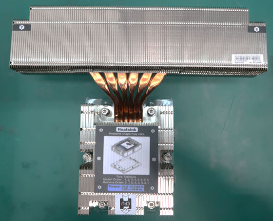
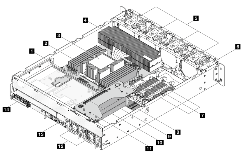
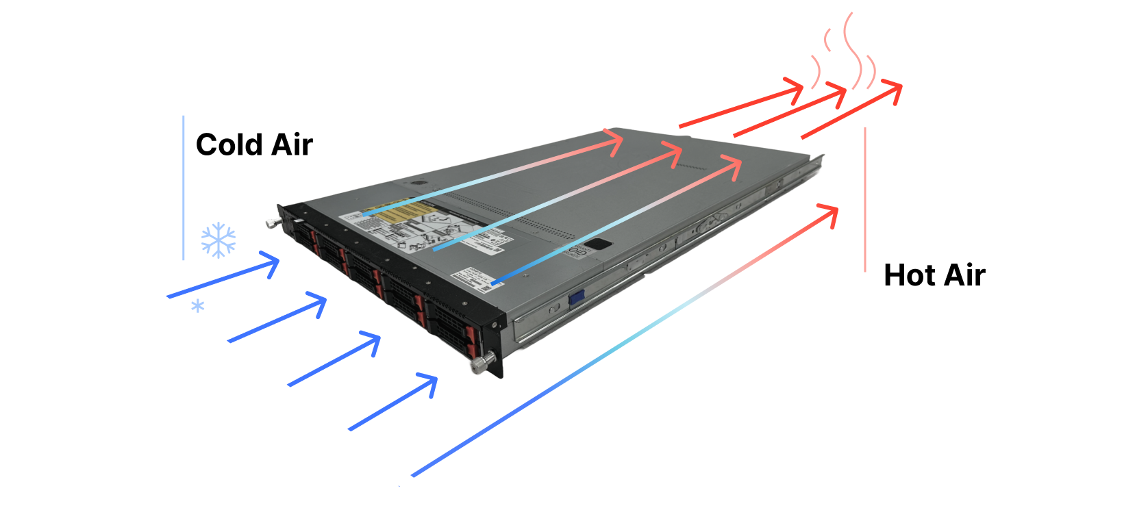
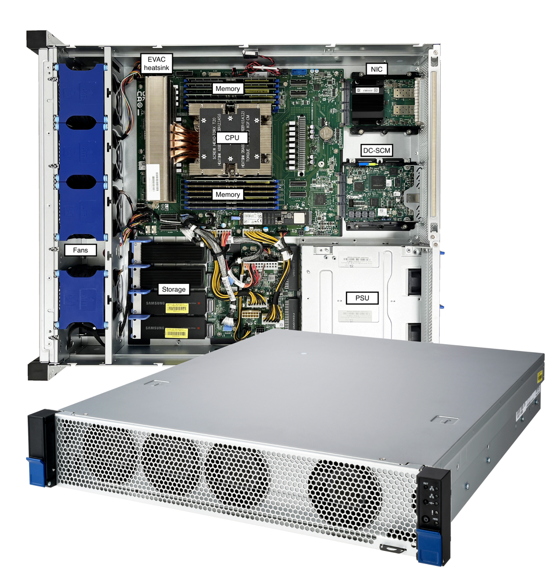
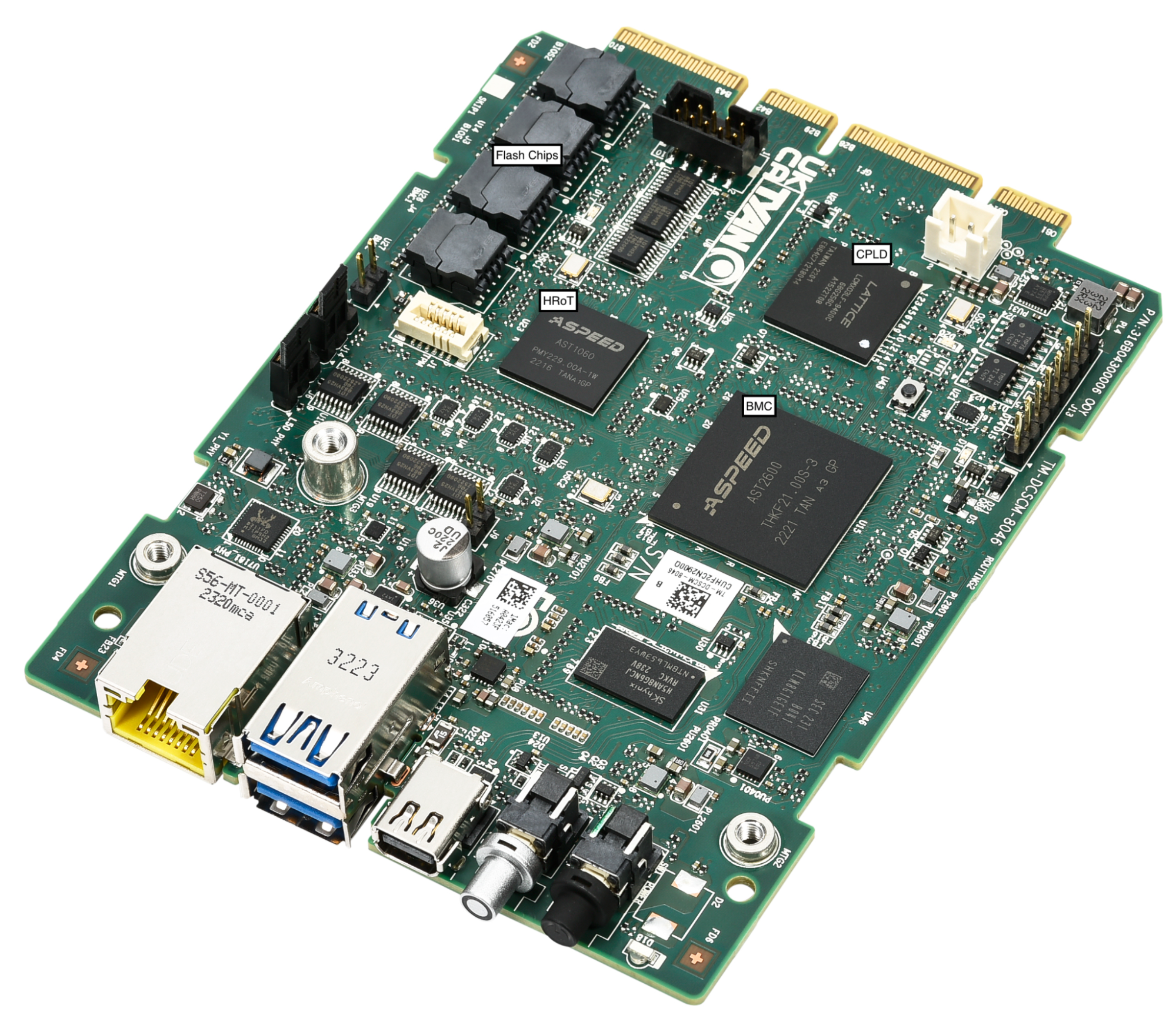
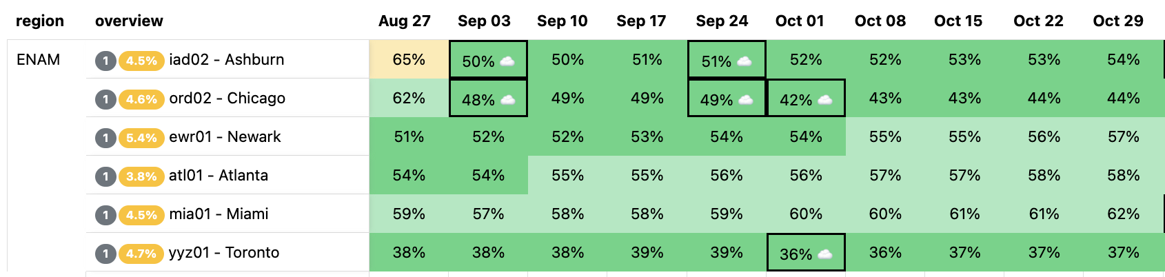
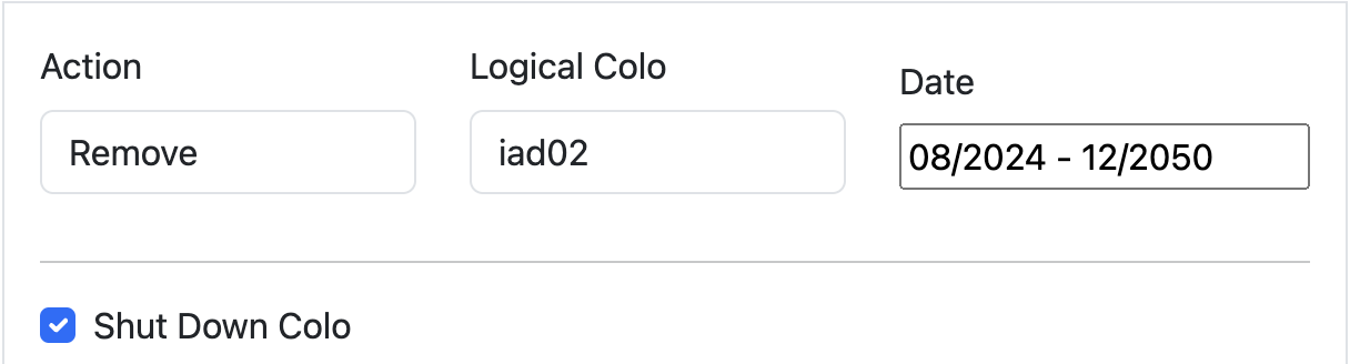
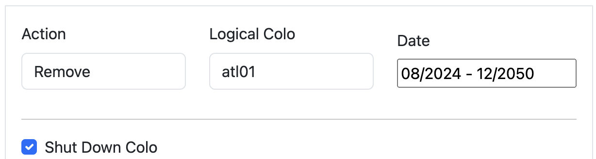
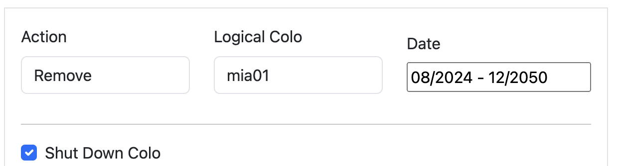
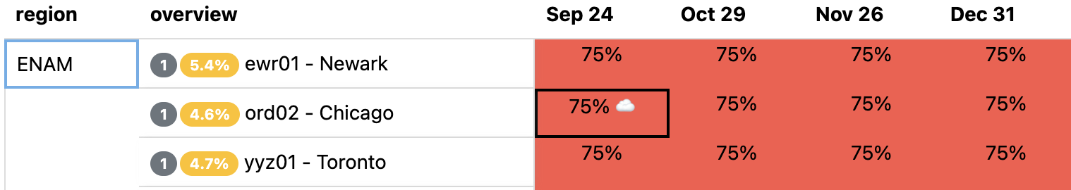
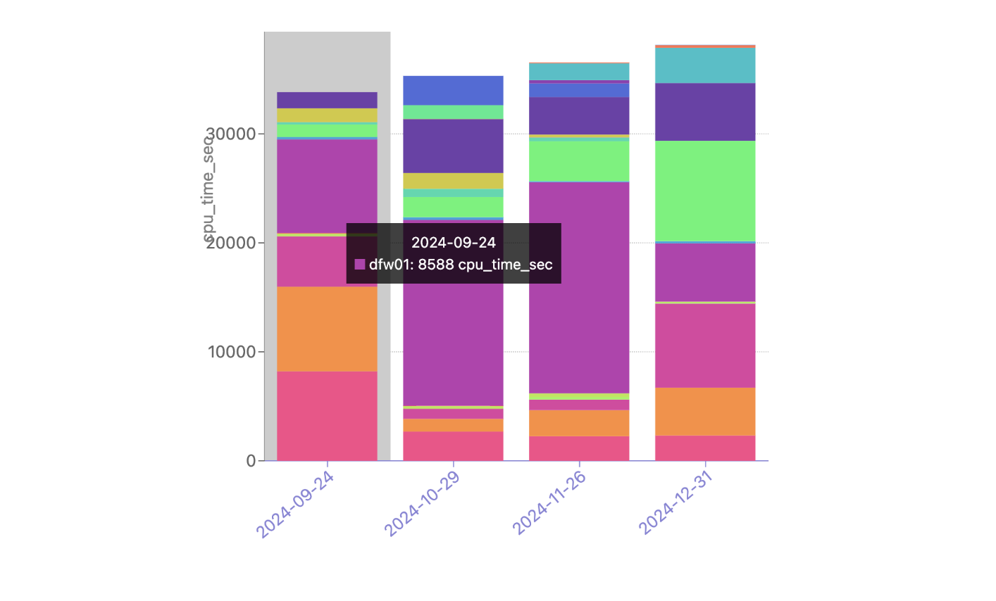

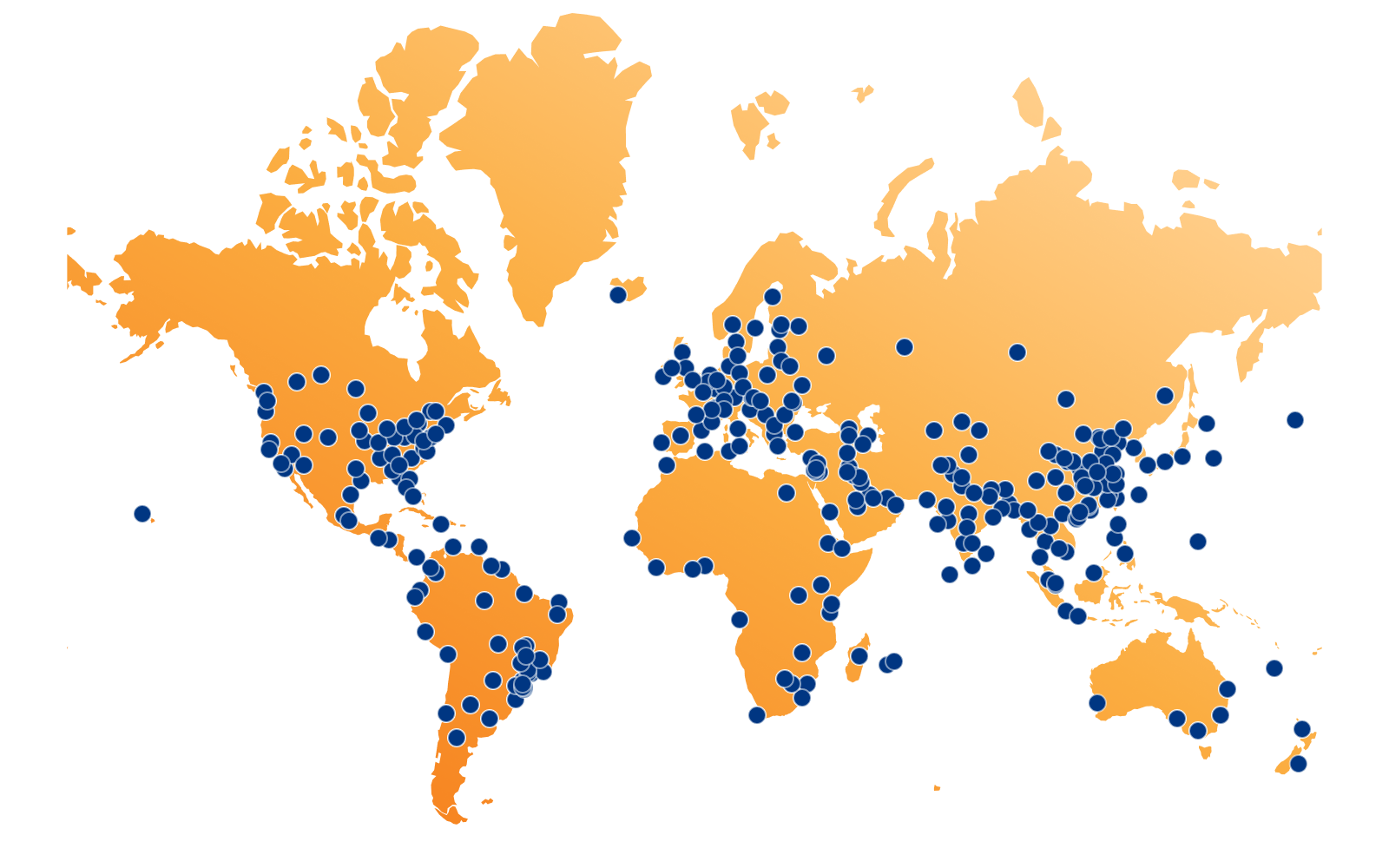

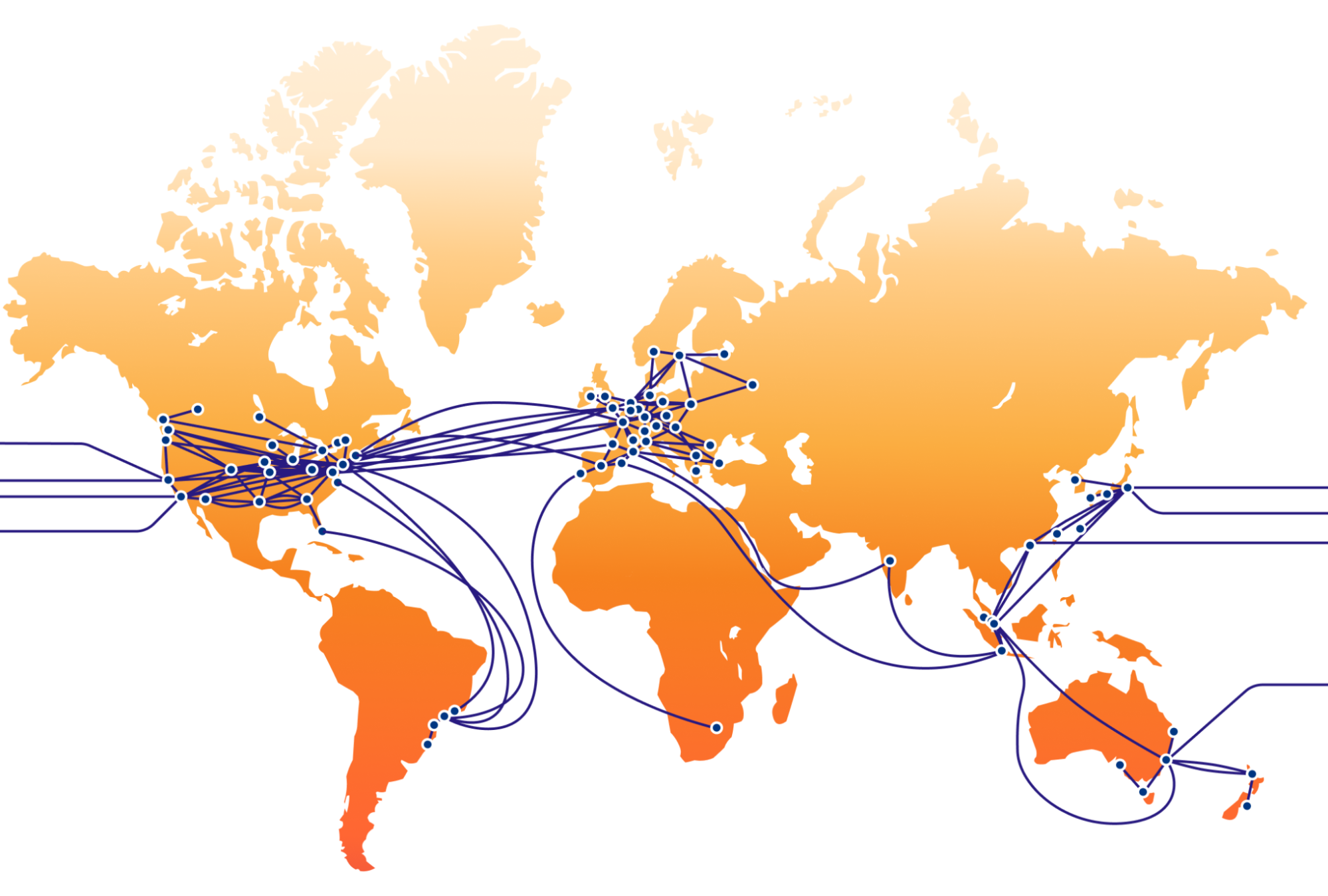
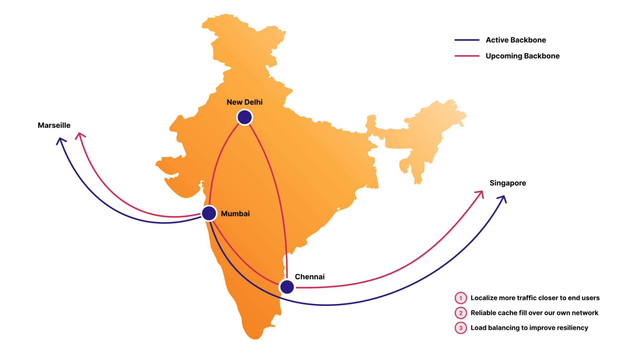
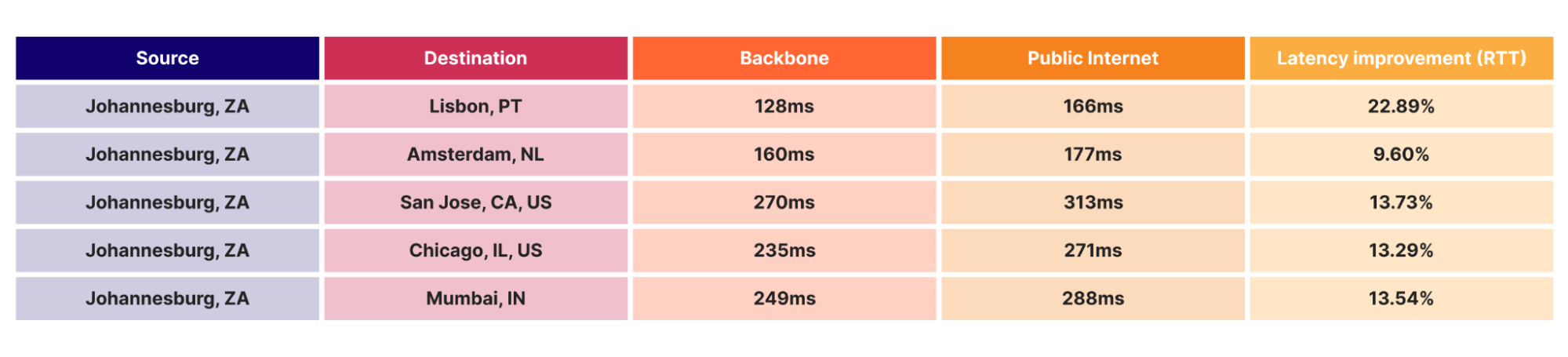

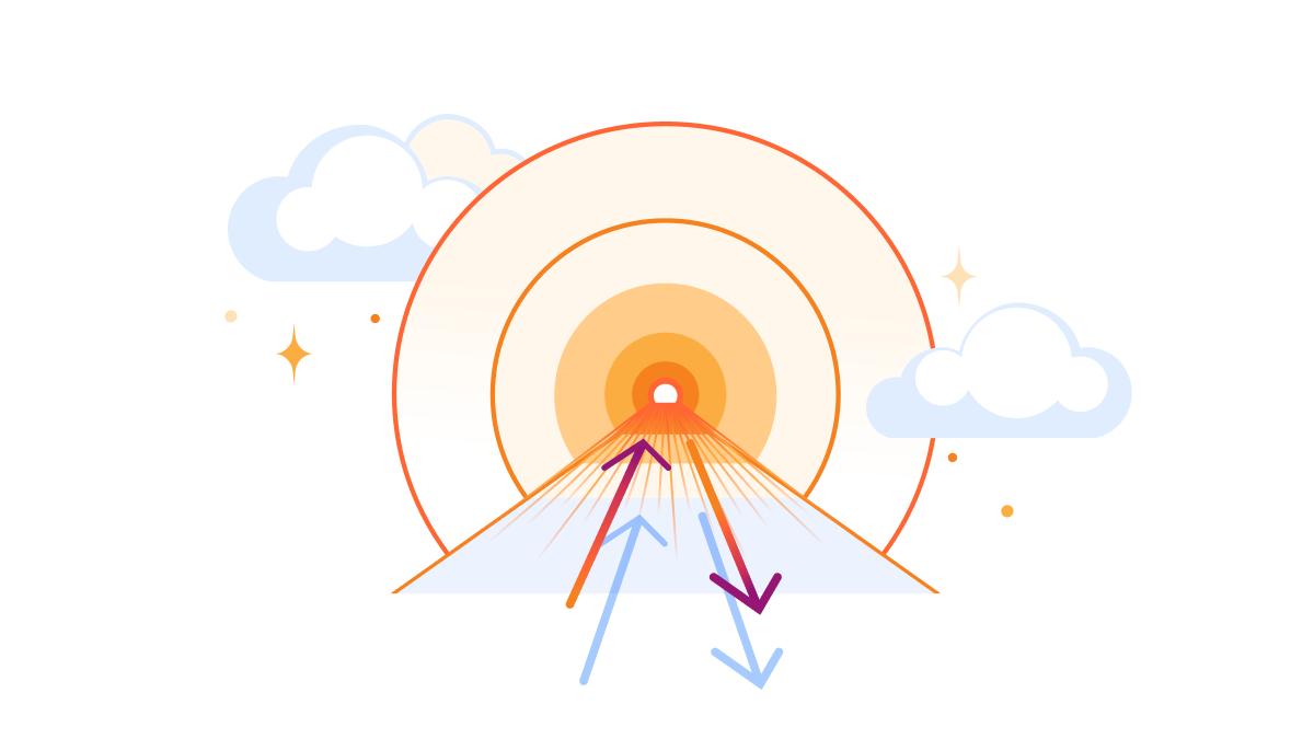
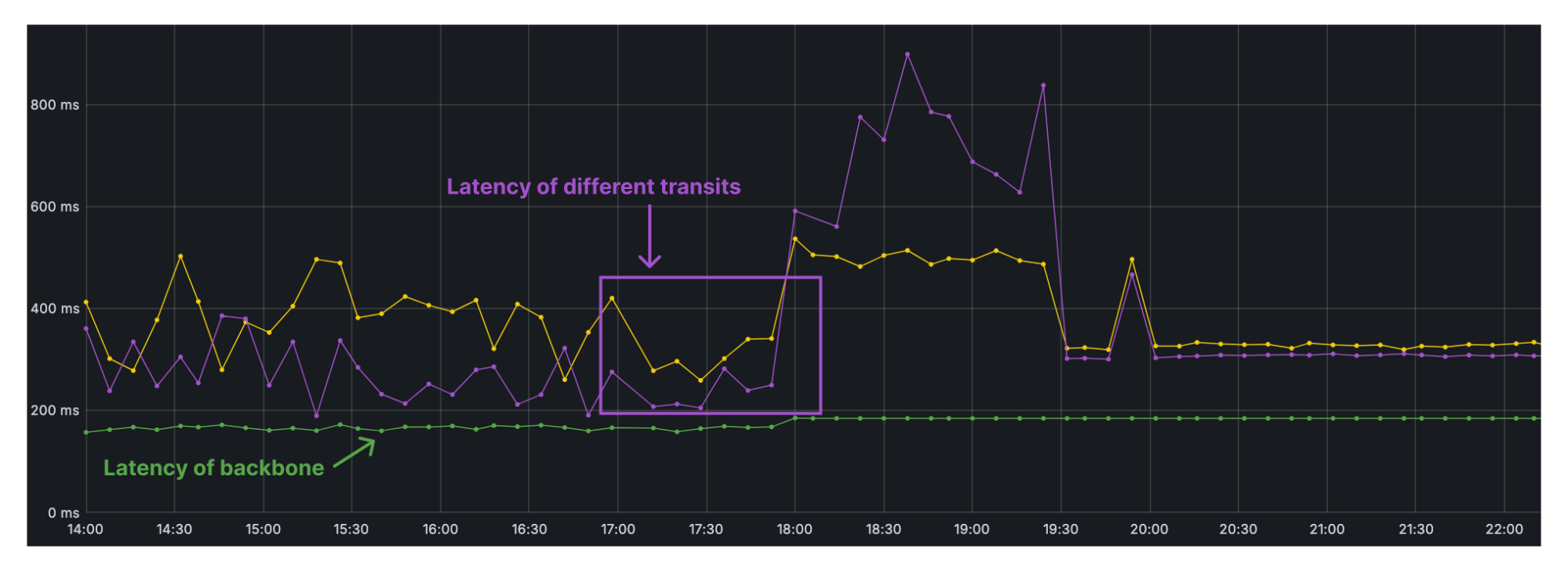


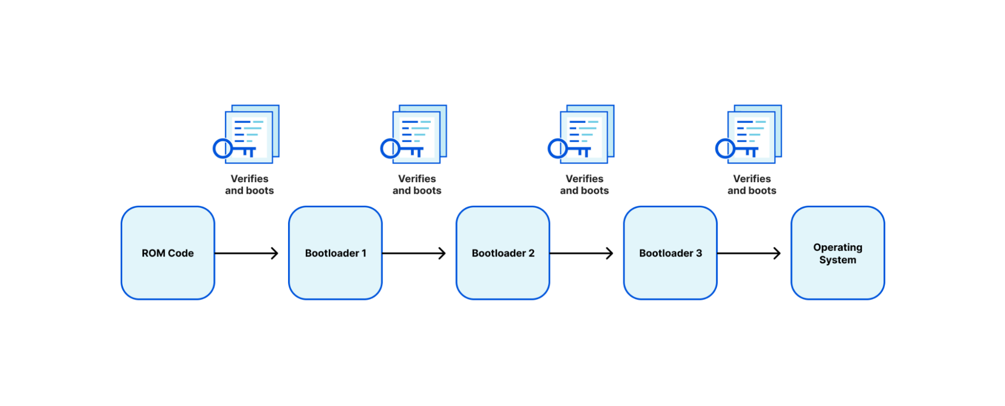

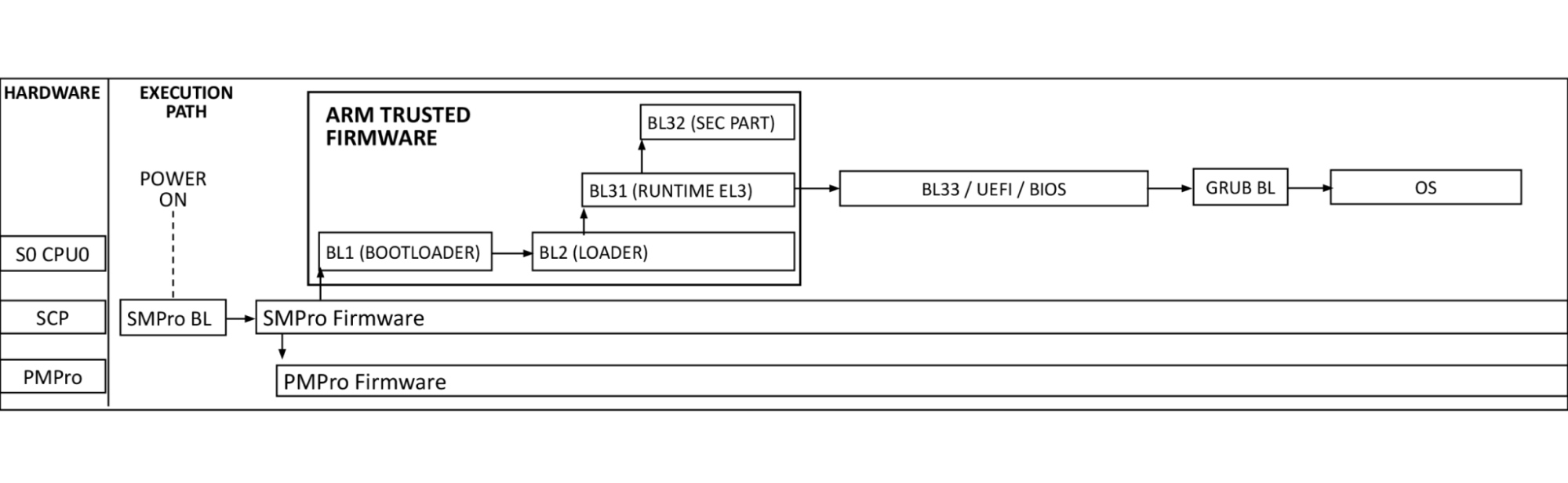
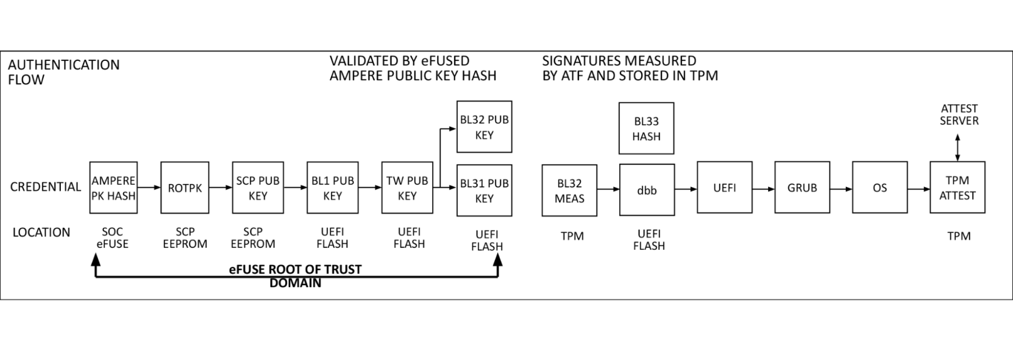
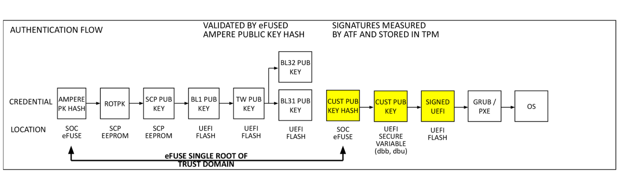
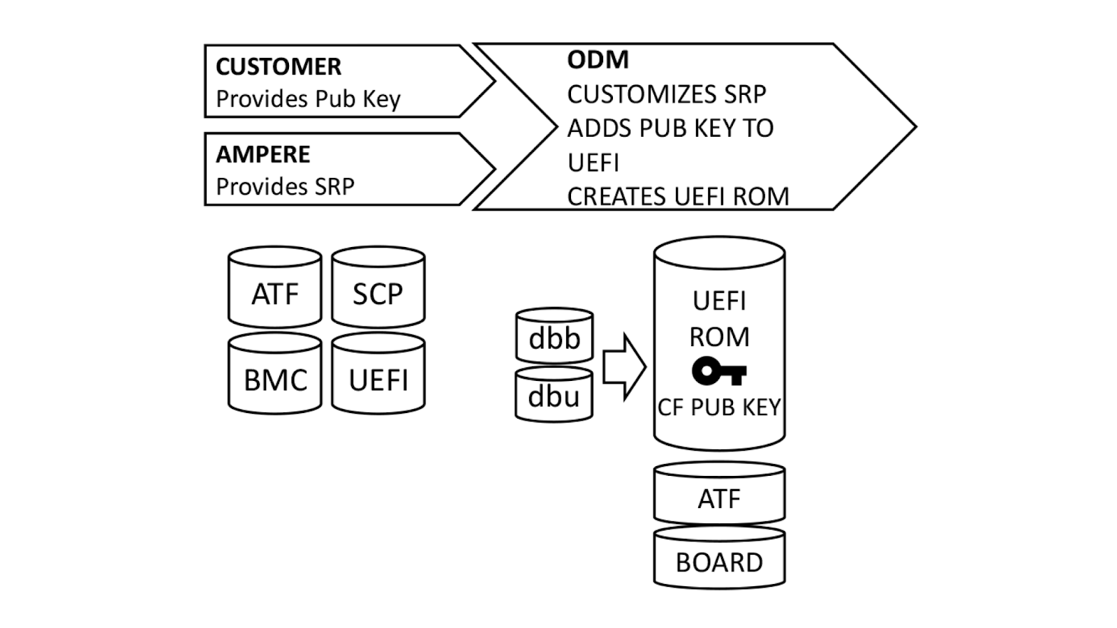
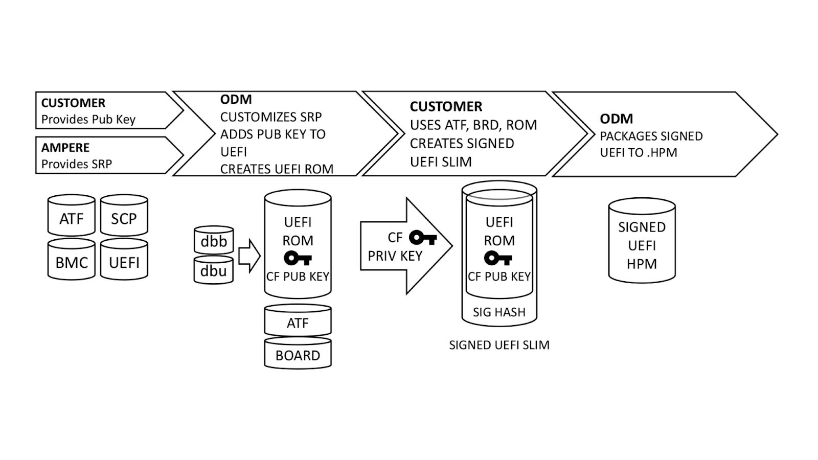
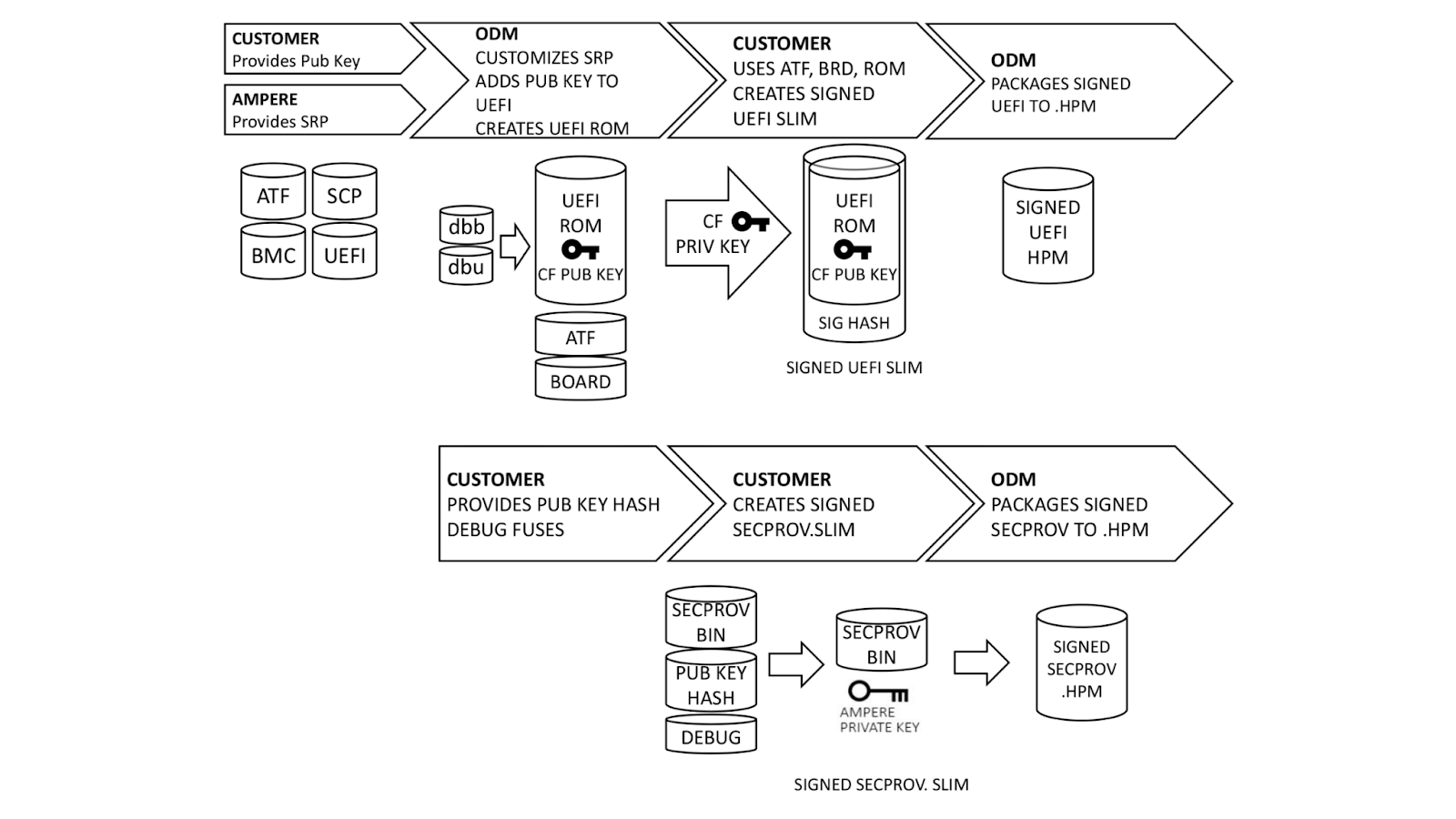
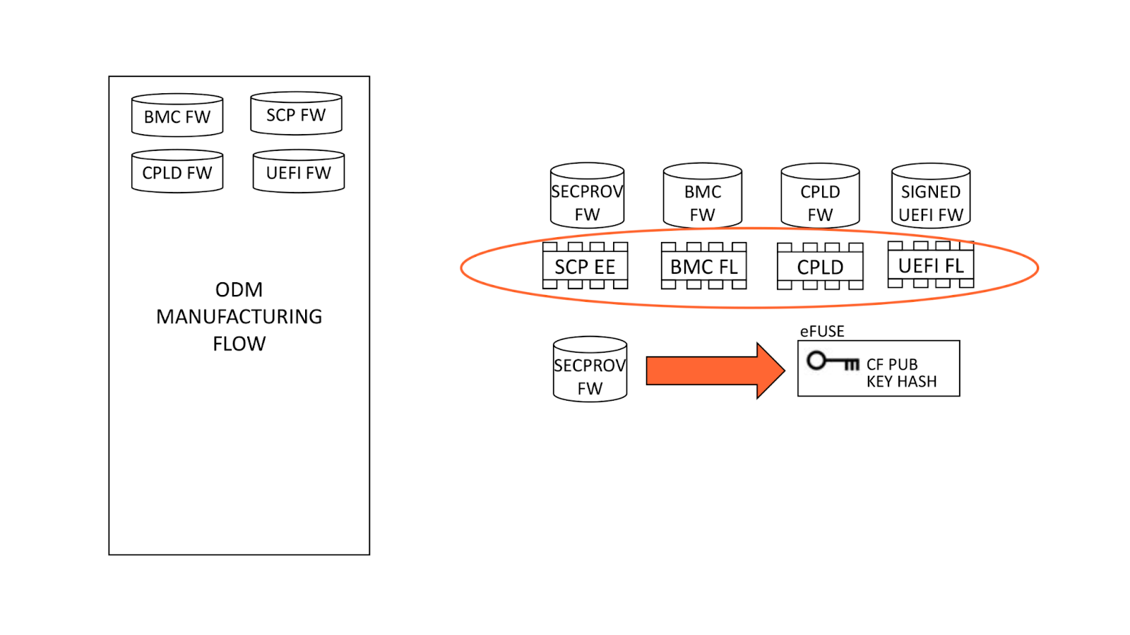
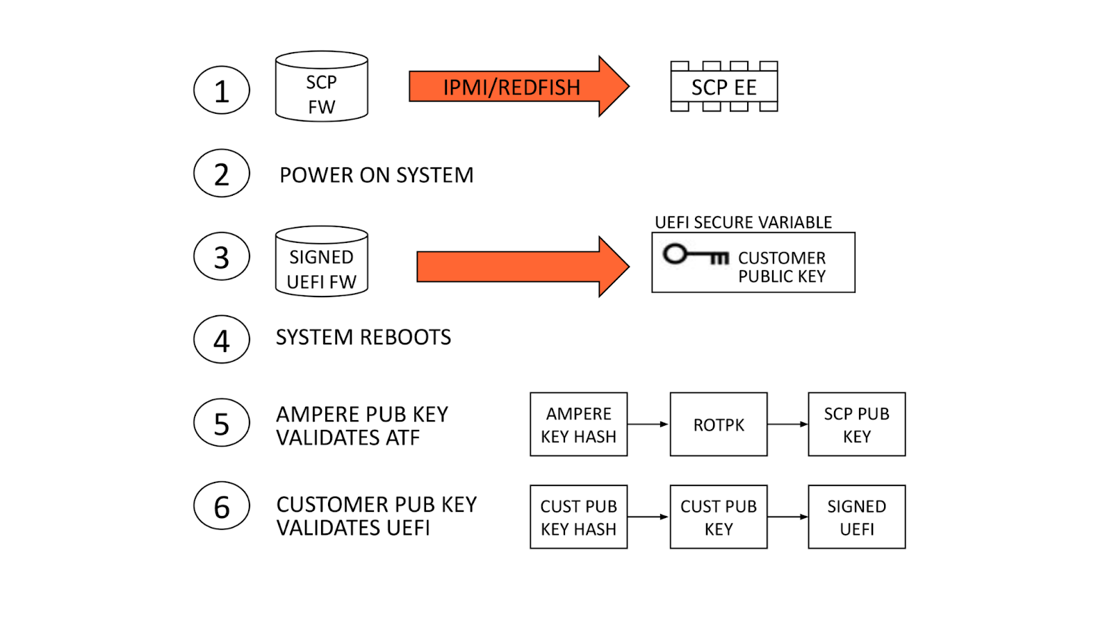
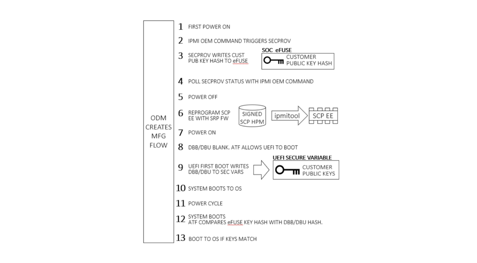
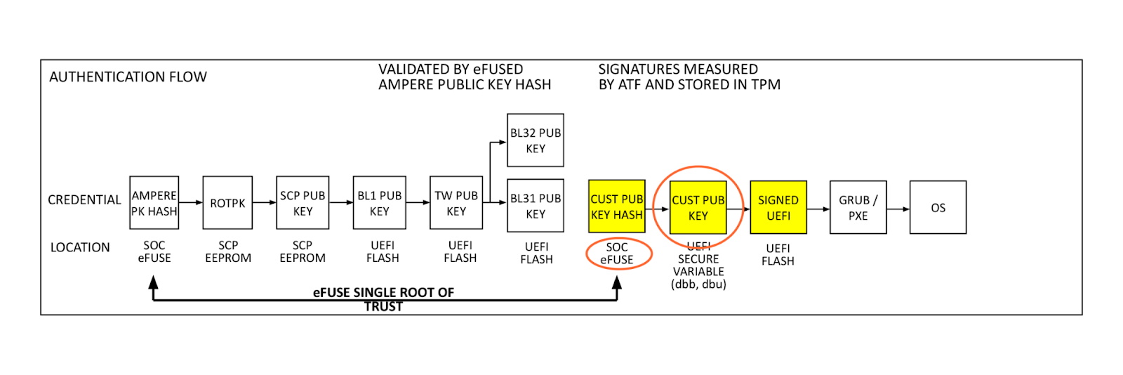


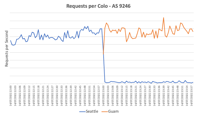
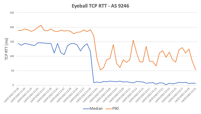
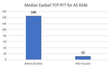
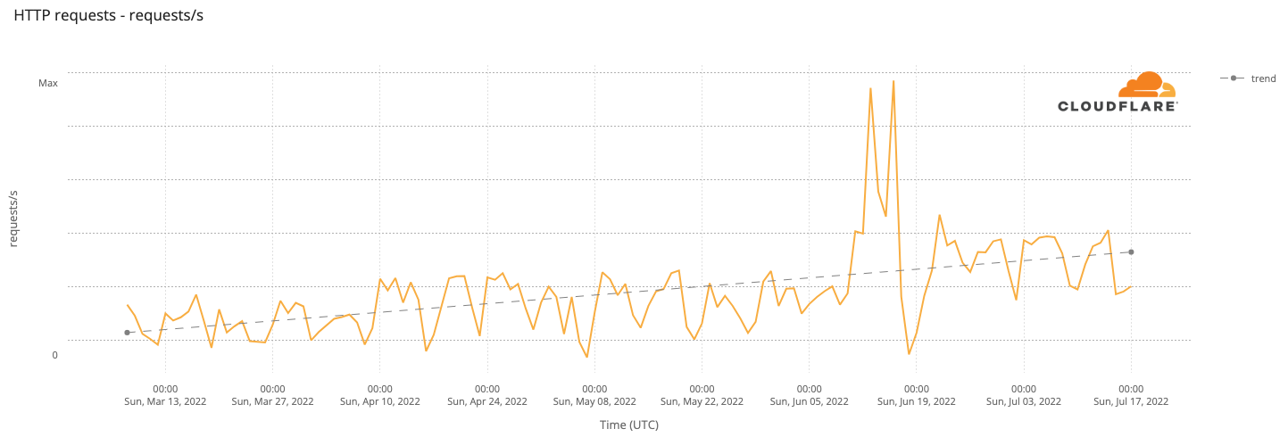

/ Pre-Performance Improvements")
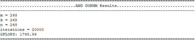
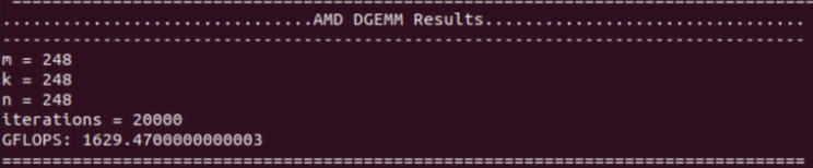


 / Post-Performance Improvements")