All posts by Subham Rakshit

On-demand and scheduled scaling of Amazon MSK Express based clusters

Post Syndicated from Subham Rakshit original https://aws.amazon.com/blogs/big-data/on-demand-and-scheduled-scaling-of-amazon-msk-express-based-clusters/

Modern streaming workloads are highly dynamic—traffic volumes fluctuate based on time of day, business cycles, or event-driven bursts. Customers need to dynamically scale Apache Kafka clusters up and down to maintain consistent throughput and performance without incurring unnecessary cost. For example, ecommerce platforms see sharp traffic increases during seasonal sales, and financial systems experience load spikes during market hours. Scaling clusters helps teams align cluster capacity with increased ingress throughput in response to these variations, leading to more efficient utilization and a better cost-to-performance ratio.

Amazon Managed Streaming for Apache Kafka (Amazon MSK) Express brokers are a key component to dynamically scaling clusters to meet demand. Express based clusters deliver 3 times higher throughput, 20 times faster scaling capabilities, and 90% faster broker recovery compared to Amazon MSK Provisioned clusters. In addition, Express brokers support intelligent rebalancing for 180 times faster operation performance, so partitions are automatically and consistently well distributed across brokers. This feature is enabled by default for all new Express based clusters and comes at no additional cost to customers. This capability alleviates the need for manual partition management when modifying cluster capacity. Intelligent rebalancing automatically tracks cluster health and triggers partition redistribution when resource imbalances are detected, maintaining performance across brokers.

This post demonstrates how to use the intelligent rebalancing feature and build a custom solution that scales Express based clusters horizontally (adding and removing brokers) dynamically based on Amazon CloudWatch metrics and predefined schedules. The solution provides capacity management while maintaining cluster performance and minimizing overhead.

Overview of Kafka scaling

Scaling Kafka clusters involves adding or removing brokers to the cluster while providing balanced data distribution and uninterrupted service. When new brokers are added, partition reassignment is required to evenly distribute load across the cluster. This process is typically performed manually—either through the Kafka command line tools (kafka-reassign-partitions.sh) or by using automation frameworks such as Cruise Control, which intelligently calculates and executes reassignment plans. During scale-in operations, partitions hosted on the brokers marked for removal must first be migrated to other brokers, leaving the target brokers empty before decommissioning.

Challenges of scaling Kafka dynamically

The complexity of scaling depends heavily on the underlying storage model. In deployments where broker data resides entirely on local storage, scaling involves physical data movement between brokers, which can take considerable time depending on partition size and replication factor. In contrast, environments that use tiered storage shift most of the data to remote object storage such as Amazon Simple Storage Service (Amazon S3), making scaling a largely metadata-driven operation. This significantly reduces data transfer overhead and accelerates both broker addition and removal, enabling more elastic and operationally efficient Kafka clusters.

However, scaling Kafka remains a non-trivial operation due to the interplay between storage, data movement, and broker resource utilization. When partitions are reassigned across brokers, large volumes of data must be copied over the network, often leading to network bandwidth saturation, storage bandwidth exhaustion, and elevated CPU utilization. Depending on data volume and replication factor, partition rebalancing can take several hours, during which time cluster performance and throughput might temporarily degrade and often require additional configuration to throttle the data movement. Although tools like Cruise Control automate this process, they introduce another layer of complexity: selecting the right combination of rebalancing goals (such as disk capacity, network load, or replica distribution) requires a deep understanding of Kafka internals and trade-offs between speed, balance, and stability. As a result, efficient scaling is an optimization problem, demanding careful orchestration of storage, compute, and network resources.

How Express brokers simplify scaling

Express brokers manage Kafka scaling through their decoupled compute and storage architecture. This innovative design enables unlimited storage without pre-provisioning, significantly simplifying cluster sizing and management. The separation of compute and storage resources allows Express brokers to scale faster than standard MSK brokers, enabling rapid cluster expansion within minutes. With Express brokers, administrators can adjust capacity both vertically and horizontally as needed, alleviating the need for over-provisioning. The architecture provides sustained broker throughput during scaling operations, with Express brokers capable of handling 500 MBps ingress and 1000 MBps egress on m7g.16xl instances. For more information about how the scaling process works in Express based clusters, see Express brokers for Amazon MSK: Turbo-charged Kafka scaling with up to 20 times faster performance.

Added to this faster scaling capability, when you add or remove brokers from your Express based clusters, intelligent rebalancing automatically redistributes partitions to balance resource utilization across the brokers. This makes sure the cluster continues to operate at peak performance, making scaling in and out possible with a single update operation. Intelligent rebalancing is enabled by default on new Express broker clusters and continuously monitors cluster health for resource imbalances or hotspots. For example, if certain brokers become overloaded due to uneven distribution of partitions or skewed traffic patterns, intelligent rebalancing will automatically move partitions to less utilized brokers to restore balance.

Finally, Express based clusters automate client configuration of broker bootstrap connection strings to allow clients to connect to clusters seamlessly as brokers are added and removed. Express based clusters provide three connection strings, one per Availability Zone, which are independent of the brokers in the cluster. This means clients only need to configure these connection strings to maintain consistent connections as brokers are added or removed. These key capabilities of Express based clusters—rapid scaling, intelligent rebalancing, and dynamic broker bootstrapping—are critical to enabling dynamic scaling in Kafka clusters. In the following section, we explore how we use these capabilities to automate the scaling process of Express based clusters.

On-demand and scheduled scaling

Leveraging fast scaling capabilities of Express brokers together with intelligent rebalancing, you can build a flexible and dynamic scaling solution to optimize your Kafka cluster resources. There are two primary approaches for automatic scaling that balance performance needs with cost efficiency: on-demand and scheduled scaling.

On-demand scaling

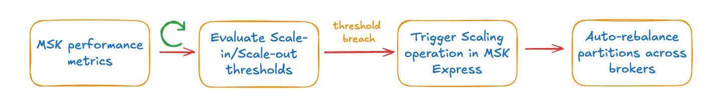
On-demand scaling tracks cluster performance and responds to capacity demands. This approach addresses scenarios where workload patterns experience traffic spikes. On-demand scaling tracks Amazon MSK performance indicators as CPU utilization and network ingress and egress throughput per broker. Beyond these infrastructure metrics, the solution also supports using CloudWatch metrics to enable business-logic-driven scaling decisions.

The solution evaluates the performance metrics continuously against configurable thresholds to determine when scaling actions are necessary. When brokers operate above capacity thresholds consistently over a period of time, it invokes an Amazon MSK API to increase the broker count of the cluster. The solution in this post currently supports horizontal scaling (adding and removing brokers) only. Intelligent rebalancing will then automatically redistribute the partitions to spread the load across the new brokers that are added. Similarly, when utilization drops below thresholds, the solution invokes an Amazon MSK API to remove brokers. The rebalancing process automatically moves partitions from the broker marked for removal to other brokers in the cluster. This solution requires topics to have sufficient partitions to support rebalancing to new brokers as brokers are added.

The following diagram illustrates the on-demand scaling workflow.

This diagram illustrates the automated scaling and rebalancing workflow for Amazon Managed Streaming for Apache Kafka (MSK). The process consists of four sequential stages that ensure optimal cluster performance through intelligent monitoring and automated actions.

Scheduled scaling

Scheduled scaling adjusts cluster capacity using time-based triggers. This approach is useful for applications with traffic patterns that correlate with business hours or schedules. For example, ecommerce platforms benefit from scheduled scaling during peak sale periods when customer activity peaks. Scheduled scaling is also useful for customers who want to avoid cluster modification operations during business hours. This solution uses a configurable schedule to scale out the cluster capacity before business hours to handle the anticipated traffic and scale in after business hours to reduce costs. This particular solution currently supports horizontal scaling (adding/removing brokers) only. With scheduled scaling, you can handle specific scenarios such as weekday business hours, weekend maintenance windows, or specific dates. You can also specify the desired number of brokers at scale-out and scale-in.

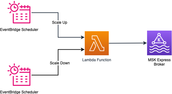
The following diagram illustrates the scheduled scaling workflow.

This horizontal process flow diagram illustrates the automated scaling and rebalancing workflow for Amazon Managed Streaming for Apache Kafka (MSK). The diagram demonstrates how MSK clusters continuously monitor performance, evaluate scaling requirements, execute scaling operations, and automatically rebalance partitions to maintain optimal performance without manual intervention.

Solution overview

This solution provides scaling automation for Express brokers through two approaches:

  • On-demand scaling – Tracks built-in cluster performance metrics or custom CloudWatch metrics and adjusts broker capacity when thresholds are crossed
  • Scheduled scaling – Scales clusters based on specific schedules

In the following sections, we provide the implementation details for both scaling methods.

Prerequisites

Complete the following steps as prerequisites:

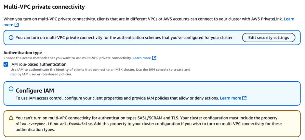
  1. Create an Express cluster with intelligent rebalancing enabled. The intelligent rebalancing feature is required for this solution to work. Note the Amazon Resource Name (ARN) of the cluster.
  2. Install Python 3.11 or higher on Amazon Elastic Compute Cloud (Amazon EC2).
  3. Install the AWS Command Line Interface (AWS CLI) and configure it with your AWS credentials.
  4. Install the AWS CDK CLI.

On-demand scaling solution

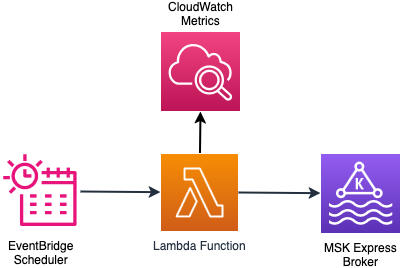
The solution uses an AWS Lambda function that is triggered by an Amazon EventBridge scheduler periodically. The Lambda function checks the cluster state and time since the last broker addition or removal was done. This is done to determine if the cluster is ready to scale. If the cluster is ready for scaling, the function collects the CloudWatch metrics that need to be evaluated to make the scaling decision. Based on the scaling configuration and using the metrics in CloudWatch, the function evaluates the scaling logic and executes the scaling decision. The scaling decision can lead to addition or removal of brokers to the cluster. In both cases, intelligent rebalancing handles partition distribution across brokers without manual intervention. You can find more details of the scaling logic in the GitHub repo.

The following diagram illustrates the architecture of the on-demand scaling solution.

This AWS architecture diagram illustrates a serverless event-driven workflow that uses Amazon EventBridge Scheduler to trigger AWS Lambda functions that interact with Amazon MSK Express brokers, with monitoring provided by Amazon CloudWatch Metrics. The diagram demonstrates a fully managed, scalable architecture for time-based or event-based Apache Kafka operations.

Deploy on-demand scaling solution

Follow these steps to deploy the on-demand scaling infrastructure. For this post, we demonstrate the on-demand scale-out functionality.

  1. Run the following commands to set the project up:
    git clone https://github.com/aws-samples/sample-msk-express-brokers-scaling.git
    cd sample-msk-express-brokers-scaling/scaling/cdk
    python -m venv .venv && source .venv/bin/activate
    pip install -r requirements.txt

  2. Modify the thresholds to match your MSK broker instance size and business requirements by editing src/config/on_demand_scaling_config.json. Refer to the configuration documentation for more details of the configuration options available.
    By default, on_demand_scaling_config.json considers the express.m7g.large broker instance size. Therefore the scale-in/scale-out ingress/egress thresholds are configured at 70% of the recommended sustained throughput for the instance size.
  3. Bootstrap your environment for use with the AWS CDK.
  4. Deploy the on-demand scaling AWS CDK application:
    cdk deploy MSKOnDemandScalingStack \
      --app "python3 msk_on_demand_scaling_stack.py" \
      --context cluster_arn="<< ARN of the MSK Cluster >>" \
      --context monitoring_frequency_minutes=1 \
      --context stack_name="MSKOnDemandScalingStack"

The monitoring_frequency_minutes parameter controls how often the EventBridge scheduler invokes the scaling logic Lambda function to evaluate cluster metrics.

The deployment creates the AWS resources required to run the on-demand scaling solution. The details of the resources created are shown in the output of the command.

Test and monitor the on-demand scaling solution

Configure the bootstrap server for your MSK cluster. You can get the bootstrap server from the AWS Management console or using the AWS CLI.

export BOOTSTRAP=<<BOOTSTRAP_SERVER>>

Create a Kafka topic in the cluster. Update the following command for the specific authentication method in Amazon MSK. Refer to the Amazon MSK Labs workshop for more details.

Topics should have a sufficient number of partitions that can be distributed across a larger set of brokers.

export TOPIC_NAME=<<TOPIC_NAME>>

bin/kafka-topics.sh \
--bootstrap-server=$BOOTSTRAP \
--create \
--replication-factor 3 \
--partitions 96 \
--topic $TOPIC_NAME

Generate load on the MSK cluster to trigger and verify the scaling operations. You can use an existing application that drives load to your cluster. You can also use the kafka-producer-perf-test.sh utility that is bundled as part of the Kafka distribution to generate load:

bin/kafka-producer-perf-test.sh \
  --topic $TOPIC_NAME \
  --num-records 1000000000 \
  --record-size 1024 \
  --throughput -1 \
  --producer-props bootstrap.servers=$BOOTSTRAP

Monitor the scaling operations by tailing the Lambda function logs:

aws logs tail /aws/lambda/MSKOnDemandScalingStack-MSKScalingFunction  \
--follow --format short

In the logs, look for the following messages to identify the exact times when scaling operations occurred. The log statements above these messages show the rationale behind the scaling decision:

[INFO] Calling MSK UpdateBrokerCount API...
 [INFO] Successfully initiated broker count update operation

The solution also creates a CloudWatch dashboard that provides visibility into scaling operations and many other broker metrics. The link to the dashboard is shown in the output of the cdk deploy command.

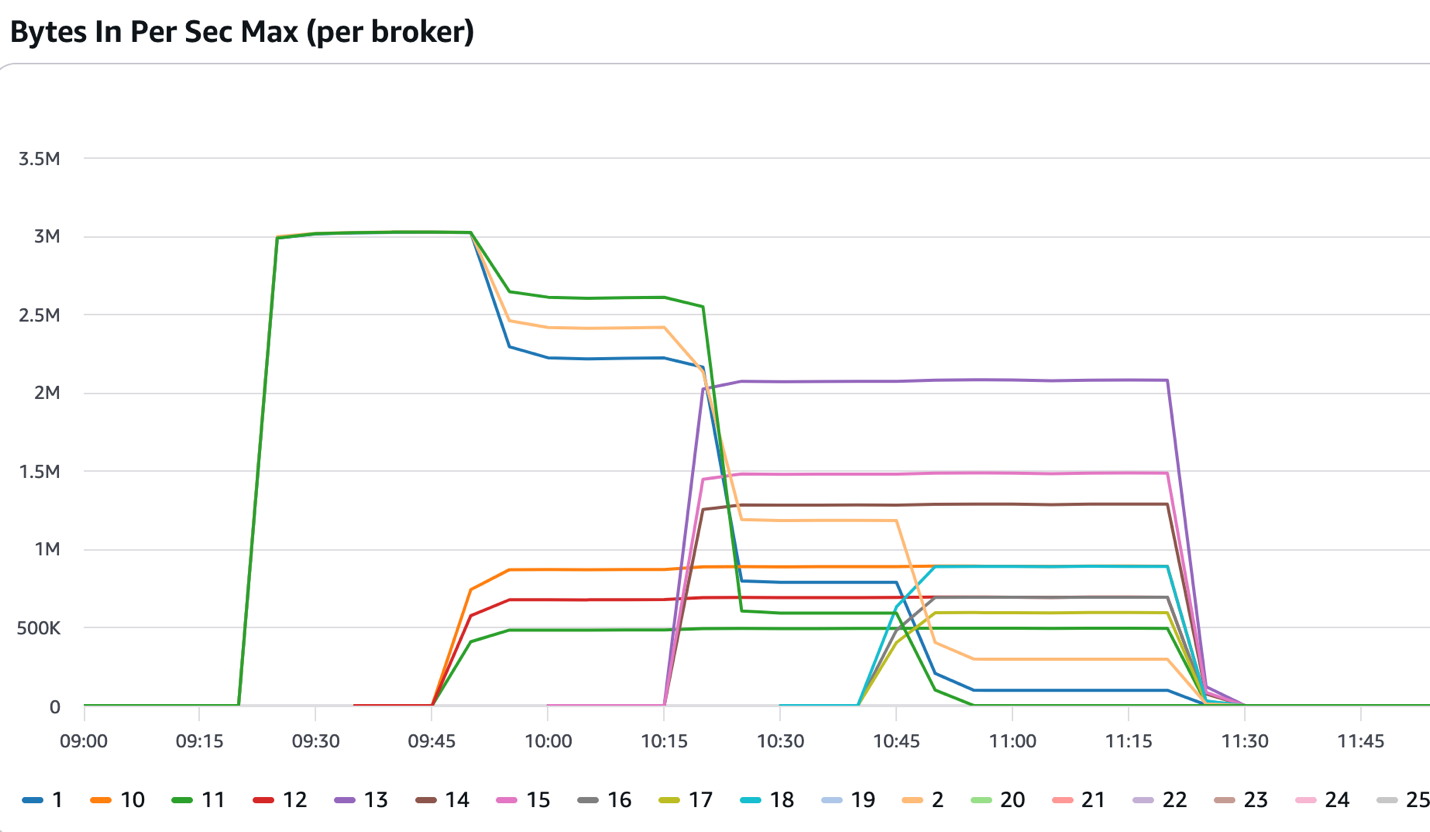
The following figure shows a cluster that started with three brokers. After the 09:15 mark, it received consistent inbound traffic, which exceeded the thresholds set in the solution. The solution added three more brokers that came into service at around the 09:45 mark. Intelligent rebalancing reassigned some of the partitions to the newly added brokers and the incoming traffic was split across six brokers. The solution continued adding more brokers until the cluster had 12 brokers and the intelligent rebalancing feature continued distributing the partitions across the newly added brokers.

Amazon MSK Broker Network Throughput Performance Chart: Bytes In Per Second Maximum by Broker This time-series line chart visualizes the maximum inbound network throughput performance across 25 individual Apache Kafka brokers in an Amazon Managed Streaming for Apache Kafka (MSK) cluster over a 3-hour time period from 09:00 to 11:45. The chart demonstrates broker-level network ingestion rates, scaling operations, and performance variations during active workload processing.

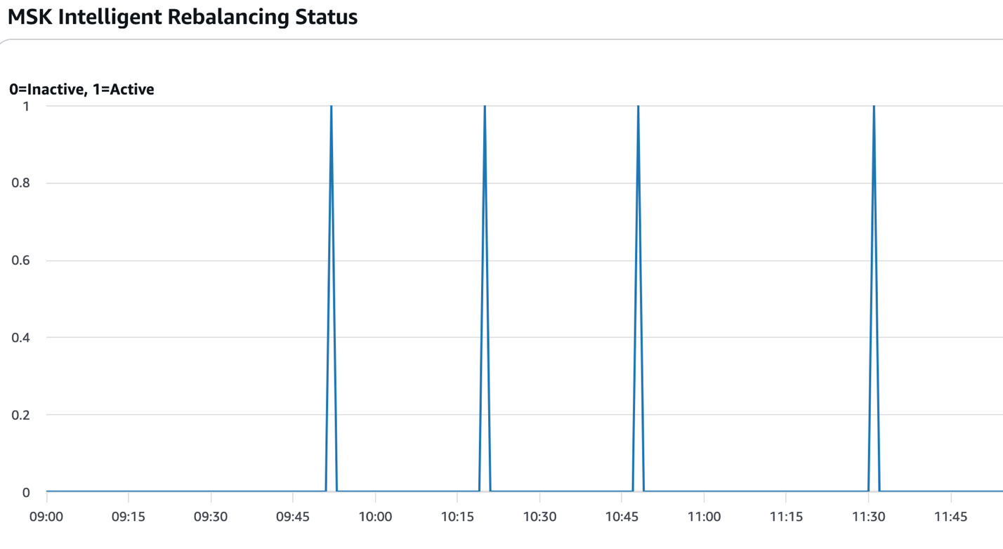
The following figure shows the times when partition rebalancing was active (value=1). In the context of this solution, that typically occurs after new brokers are added or removed and the scaling operations are complete.

Amazon MSK Intelligent Rebalancing Status Timeline Chart This binary state timeline chart visualizes the activation and deactivation cycles of Amazon Managed Streaming for Apache Kafka (MSK) Intelligent Rebalancing feature over a 2 hour and 45 minute observation period from 09:00 to 11:45. The chart displays discrete on/off status indicators showing when the automated partition rebalancing feature was actively running versus inactive.

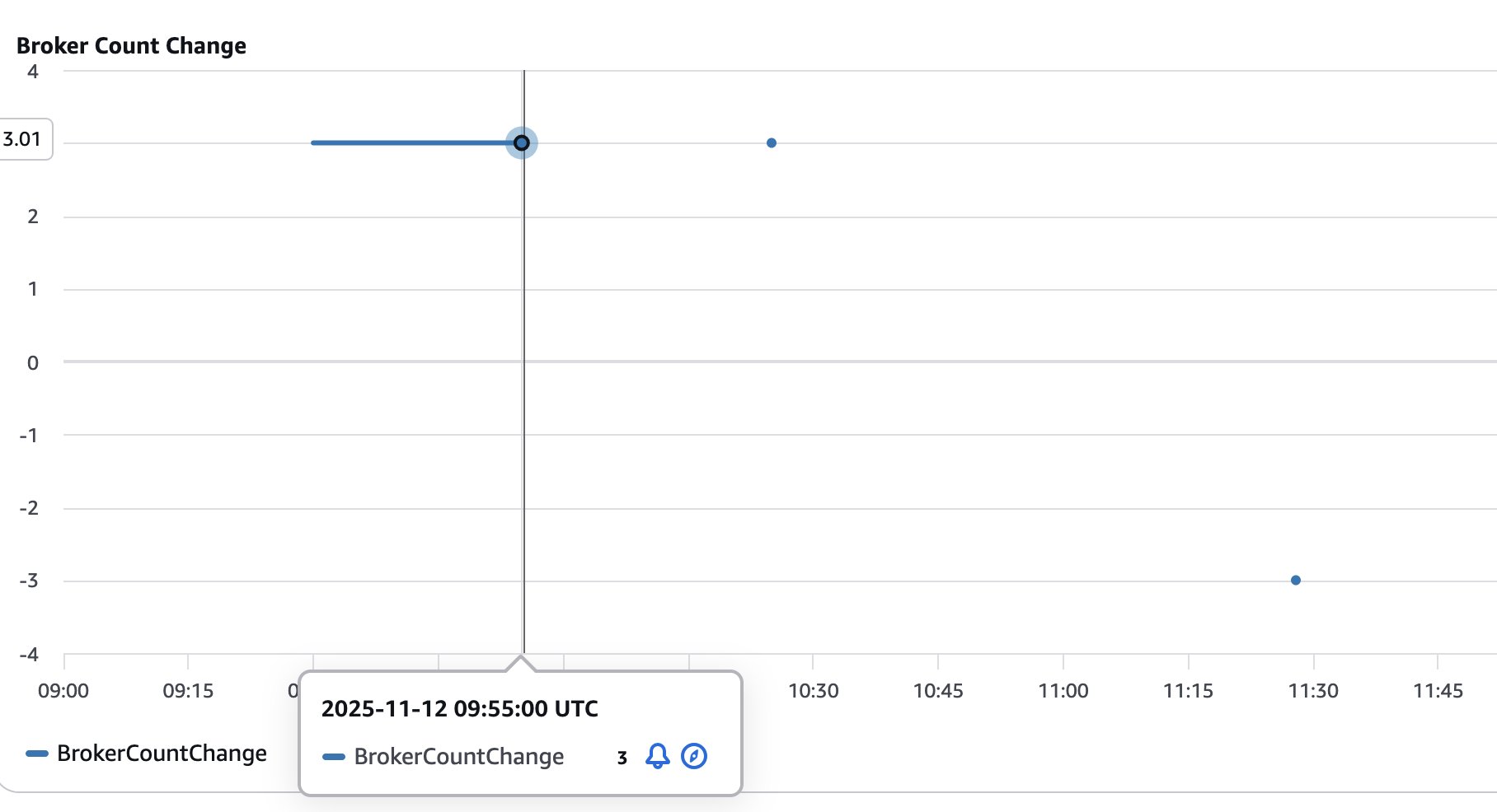
The following figure shows the number of brokers added (positive values) or removed (negative values) from the cluster. This helps visualize and track the size of the cluster as it goes through scaling operations.

Amazon MSK Broker Count Change Timeline Chart This time-series chart visualizes broker count changes in an Amazon Managed Streaming for Apache Kafka (MSK) cluster over a 2 hour and 45 minute period from 09:00 to 11:45 UTC on November 12, 2025. The chart tracks incremental additions and removals of Kafka brokers, demonstrating MSK's dynamic scaling capabilities in response to workload demands.

Scheduled scaling solution

The scheduled scaling implementation supports timing patterns through an EventBridge schedule. You can configure timing to trigger an action using cron expressions. Based on the cron expression, the EventBridge Scheduler triggers a Lambda function at the specified time to scale out or scale in. The Lambda function performs checks if the cluster is ready for a scaling operation and performs the requested scaling operation by invoking the Amazon MSK control plane API. The service allows removing only three brokers at a time from a cluster. The solution handles this scenario by repeatedly removing the brokers in counts of three until the desired number of brokers are reached.

The following diagram illustrates the architecture of the scheduled scaling solution.

This AWS architecture diagram illustrates an event-driven, time-based auto-scaling workflow where two Amazon EventBridge Scheduler instances trigger an AWS Lambda function to execute scale-up and scale-down operations on an Amazon MSK Express broker. The diagram demonstrates serverless capacity management for Apache Kafka infrastructure using scheduled automation.

Configuration parameters

EventBridge schedules support cron expressions for precise timing control, so you can fine-tune scaling operations for specific times of day and days of the week. For example, you can configure scaling to occur at 8:00 AM on weekdays using the cron expression cron(0 8 ? * MON-FRI *). To scale in at 6:00 PM on the same days, use cron(0 18 ? * MON-FRI *). For more patterns, refer to Setting a schedule pattern for scheduled rules (legacy) in Amazon EventBridge. You can also configure the desired broker count to be reached during scale-out and scale-in operations.

Deploy scheduled scaling solution

Follow these steps to deploy the scheduled scaling solution:

  1. Run the following commands to set the project up:
    cd scaling/cdk
    python3 -m venv .venv && source .venv/bin/activate
    pip install -r requirements.txt

  2. Modify the scaling schedule by editing scaling/cdk/src/config/scheduled_scaling_config.json. Refer to the configuration documentation for more details of the configuration options available.
  3. Deploy the scheduled scaling AWS CDK application:
    cdk deploy MSKScheduledScalingStack \
        --app "python3 msk_scheduled_scaling_stack.py" \
        --context cluster_arn="<< ARN of the MSK Cluster >>" \
        --context stack_name="MSKScheduledScalingStack"

Test and monitor the scheduled scaling solution

The scheduled scaling is triggered as specified in the EventBridge Scheduler cron. However, if you want to test the scale-out operations, run the following command to manually invoke the Lambda function:

aws lambda invoke \
  --function-name MSKScheduledScalingStack-MSKScheduledScalingFunction \
  --payload '{"source":"aws.scheduler.scale-out","detail":{"action":"scale_out","schedule_name":"MSKScheduledScaleOut"}}' \
  --cli-binary-format raw-in-base64-out \
  response.json

Similarly, you can manually start a scale-in operation by running the following command:

aws lambda invoke \
  --function-name MSKScheduledScalingStack-MSKScheduledScalingFunction \
  --payload '{"source":"aws.scheduler.scale-in","detail":{"action":"scale_in","schedule_name":"MSKScheduledScaleIn"}}' \
  --cli-binary-format raw-in-base64-out \
  response.json

Monitor the scaling operations by tailing the Lambda function logs:

aws logs tail /aws/lambda/MSKScheduledScalingStack-MSKScheduledScalingFunction  \
--follow --format short

You can monitor scheduled scaling using the CloudWatch dashboard as described in the on-demand scaling section.

Review scaling configuration parameters

The configuration parameters for both on-demand and scheduled scaling are documented in Configuration Options. These configurations give you flexibility to change how and when the scaling happens. It is important to go through the configuration parameters and make sure they meet your business requirement. For on-demand scaling, you can scale the cluster based on built-in performance metrics or custom metrics (for example MessagesInPerSec).

Considerations

Keep in mind the following considerations when deploying either solution:

  • EventBridge notifications for scaling failures – Both on-demand and scheduled scaling solutions publish EventBridge notifications when scaling operations fail. Create EventBridge rules to route these failure events to your monitoring and alerting system to detect failures in scaling and respond to them. For details on event sources, types, and payloads, refer to the EventBridge notifications section in the GitHub repo.
  • Cool-down period management – Properly configure cool-down periods to prevent scaling oscillations where the cluster repeatedly scales out and scales in rapidly. Oscillations typically occur when traffic patterns have short-term spikes that don’t represent sustained demand. Oscillations can also happen when thresholds are set too close to normal operating levels. Set cool-down periods based on your workload characteristics and the scaling completion times. Also consider different cool-down periods for scale-out vs. scale-in operations by setting longer cool-down periods for scale-in operations (scale_in_cooldown_minutes) compared to scaling out (scale_out_cooldown_minutes). Test cool-down settings under realistic load patterns before production deployment to achieve optimal performance.
  • Cost control through monitoring frequency – The solution incurs costs for services like Lambda functions, EventBridge schedules, CloudWatch metrics, and logs that are used in the solution. Both on-demand and scheduled scaling solutions work by running periodically to check the cluster health status and if a scaling operation needs to be performed. The default 1-minute monitoring frequency provides responsive scaling but increases other costs associated with the solution. Consider increasing the monitoring interval based on your workload characteristics to balance scaling responsiveness and the cost incurred by the solution. You can change the monitoring frequency by changing the monitoring_frequency_minutes when you deploy the solution.
  • Solution isolation – The on-demand and scheduled scaling solutions were designed and tested in isolation to support predictable behavior and optimal performance. You can deploy either solution, but avoid running both solutions simultaneously on the same cluster. Using both approaches together can cause unpredictable scaling behavior where the solutions might conflict with each other’s scaling decisions, leading to resource contention and potential scaling oscillations. Choose the approach that best matches your workload patterns and deploy only one scaling solution per cluster.

Clean up

Follow these steps to delete the resources created by the solution. Make sure all the scaling operations that are in flight are completed before you run the cleanup.Delete the on-demand scaling solution with the following code:

cdk destroy MSKOnDemandScalingStack --app "python3 msk_on_demand_scaling_stack.py" --context cluster_arn="<MSK_CLUSTER_ARN>"

Delete the scheduled scaling solution with the following code:

cdk destroy MSKScheduledScalingStack --app "python3 msk_scheduled_scaling_stack.py" --context cluster_arn="<MSK_CLUSTER_ARN>"

Summary

In this post, we showed how to use intelligent rebalancing to scale your Express based cluster based on your business requirements without requiring manual partition rebalancing. You can extend the solution to use the specific CloudWatch metrics that your business depends on to dynamically scale your Kafka cluster. Similarly, you can adjust the scheduled scaling solution to scale out and scale in your cluster when you anticipate significant change in traffic to your cluster at specific times.To learn more about the services used in this solution, refer to the following resources:


About the authors

Subham Rakshit

Subham Rakshit

Subham is a Senior Streaming Solutions Architect for Analytics at AWS based in the UK. He works with customers to design and build streaming architectures so they can get value from analysing their streaming data. His two little daughters keep him occupied most of the time outside work, and he loves solving jigsaw puzzles with them.

Rakshith Rao

Rakshith Rao

Rakshith is a Senior Solutions Architect at AWS. He works with AWS’s strategic customers to build and operate their key workloads on AWS.

Build multi-Region resilient Apache Kafka applications with identical topic names using Amazon MSK and Amazon MSK Replicator

Post Syndicated from Subham Rakshit original https://aws.amazon.com/blogs/big-data/build-multi-region-resilient-apache-kafka-applications-with-identical-topic-names-using-amazon-msk-and-amazon-msk-replicator/

Resilience has always been a top priority for customers running mission-critical Apache Kafka applications. Amazon Managed Streaming for Apache Kafka (Amazon MSK) is deployed across multiple Availability Zones and provides resilience within an AWS Region. However, mission-critical Kafka deployments require cross-Region resilience to minimize downtime during service impairment in a Region. With Amazon MSK Replicator, you can build multi-Region resilient streaming applications to provide business continuity, share data with partners, aggregate data from multiple clusters for analytics, and serve global clients with reduced latency. This post explains how to use MSK Replicator for cross-cluster data replication and details the failover and failback processes while keeping the same topic name across Regions.

MSK Replicator overview

Amazon MSK offers two cluster types: Provisioned and Serverless. Provisioned cluster supports two broker types: Standard and Express. With the introduction of Amazon MSK Express brokers, you can now deploy MSK clusters that significantly reduce recovery time by up to 90% while delivering consistent performance. Express brokers provide up to 3 times the throughput per broker and scale up to 20 times faster compared to Standard brokers running Kafka. MSK Replicator works with both broker types in Provisioned clusters and along with Serverless clusters.

MSK Replicator supports an identical topic name configuration, enabling seamless topic name retention during both active-active or active-passive replication. This avoids the risk of infinite replication loops commonly associated with third-party or open source replication tools. When deploying an active-passive cluster architecture for regional resilience, where one cluster handles live traffic and the other acts as a standby, an identical topic configuration simplifies the failover process. Applications can transition to the standby cluster without reconfiguration because topic names remain consistent across the source and target clusters.

To set up an active-passive deployment, you have to enable multi-VPC connectivity for the MSK cluster in the primary Region and deploy an MSK Replicator in the secondary Region. The replicator will consume data from the primary Region’s MSK cluster and asynchronously replicate it to the secondary Region. You connect the clients initially to the primary cluster but fail over the clients to the secondary cluster in the case of primary Region impairment. When the primary Region recovers, you deploy a new MSK Replicator to replicate data back from the secondary cluster to the primary. You need to stop the client applications in the secondary Region and restart them in the primary Region.

Because replication with MSK Replicator is asynchronous, there is a possibility of duplicate data in the secondary cluster. During a failover, consumers might reprocess some messages from Kafka topics. To address this, deduplication should occur on the consumer side, such as by using an idempotent downstream system like a database.

In the next sections, we demonstrate how to deploy MSK Replicator in an active-passive architecture with identical topic names. We provide a step-by-step guide for failing over to the secondary Region during a primary Region impairment and failing back when the primary Region recovers. For an active-active setup, refer to Create an active-active setup using MSK Replicator.

Solution overview

In this setup, we deploy a primary MSK Provisioned cluster with Express brokers in the us-east-1 Region. To provide cross-Region resilience for Amazon MSK, we establish a secondary MSK cluster with Express brokers in the us-east-2 Region and replicate topics from the primary MSK cluster to the secondary cluster using MSK Replicator. This configuration provides high resilience within each Region by using Express brokers, and cross-Region resilience is achieved through an active-passive architecture, with replication managed by MSK Replicator.

The following diagram illustrates the solution architecture.

The primary Region MSK cluster handles client requests. In the event of a failure to communicate to MSK cluster due to primary region impairment, you need to fail over the clients to the secondary MSK cluster. The producer writes to the customer topic in the primary MSK cluster, and the consumer with the group ID msk-consumer reads from the same topic. As part of the active-passive setup, we configure MSK Replicator to use identical topic names, making sure that the customer topic remains consistent across both clusters without requiring changes from the clients. The entire setup is deployed within a single AWS account.

In the next sections, we describe how to set up a multi-Region resilient MSK cluster using MSK Replicator and also show the failover and failback strategy.

Provision an MSK cluster using AWS CloudFormation

We provide AWS CloudFormation templates to provision certain resources:

This will create the virtual private cloud (VPC), subnets, and the MSK Provisioned cluster with Express brokers within the VPC configured with AWS Identity and Access Management (IAM) authentication in each Region. It will also create a Kafka client Amazon Elastic Compute Cloud (Amazon EC2) instance, where we can use the Kafka command line to create and view a Kafka topic and produce and consume messages to and from the topic.

Configure multi-VPC connectivity in the primary MSK cluster

After the clusters are deployed, you need to enable the multi-VPC connectivity in the primary MSK cluster deployed in us-east-1. This will allow MSK Replicator to connect to the primary MSK cluster using multi-VPC connectivity (powered by AWS PrivateLink). Multi-VPC connectivity is only required for cross-Region replication. For same-Region replication, MSK Replicator uses an IAM policy to connect to the primary MSK cluster.

MSK Replicator uses IAM authentication only to connect to both primary and secondary MSK clusters. Therefore, although other Kafka clients can still continue to use SASL/SCRAM or mTLS authentication, for MSK Replicator to work, IAM authentication has to be enabled.

To enable multi-VPC connectivity, complete the following steps:

  1. On the Amazon MSK console, navigate to the MSK cluster.
  2. On the Properties tab, under Network settings, choose Turn on multi-VPC connectivity on the Edit dropdown menu.

  1. For Authentication type, select IAM role-based authentication.
  2. Choose Turn on selection.

Enabling multi-VPC connectivity is a one-time setup and it can take approximately 30–45 minutes depending on the number of brokers. After this is enabled, you need to provide the MSK cluster resource policy to allow MSK Replicator to talk to the primary cluster.

  1. Under Security settings¸ choose Edit cluster policy.
  2. Select Include Kafka service principal.

Now that the cluster is enabled to receive requests from MSK Replicator using PrivateLink, we need to set up the replicator.

Create a MSK Replicator

Complete the following steps to create an MSK Replicator:

  1. In the secondary Region (us-east-2), open the Amazon MSK console.
  2. Choose Replicators in the navigation pane.
  3. Choose Create replicator.
  4. Enter a name and optional description.

  1. In the Source cluster section, provide the following information:
    1. For Cluster region, choose us-east-1.
    2. For MSK cluster, enter the Amazon Resource Name (ARN) for the primary MSK cluster.

For cross-Region setup, the primary cluster will appear disabled if the multi-VPC connectivity is not enabled and the cluster resource policy is not configured in the primary MSK cluster. After you choose the primary cluster, it automatically selects the subnets associated with primary cluster. Security groups are not required because the primary cluster’s access is governed by the cluster resource policy.

Next, you select the target cluster. The target cluster Region is defaulted to the Region where the MSK Replicator is created. In this case, it’s us-east-2.

  1. In the Target cluster section, provide the following information:
    1. For MSK cluster, enter the ARN of the secondary MSK cluster. This will automatically select the cluster subnets and the security group associated with the secondary cluster.
    2. For Security groups, choose any additional security groups.

Make sure that the security groups have outbound rules to allow traffic to your secondary cluster’s security groups. Also make sure that your secondary cluster’s security groups have inbound rules that accept traffic from the MSK Replicator security groups provided here.

Now let’s provide the MSK Replicator settings.

  1. In the Replicator settings section, enter the following information:
    1. For Topics to replicate, we keep the topics to replicate as a default value that replicates all topics from the primary to secondary cluster.
    2. For Replication starting position, we choose Earliest, so that we can get all the events from the start of the source topics.
    3. For Copy settings, select Keep the same topic names to configure the topic name in the secondary cluster as identical to the primary cluster.

This makes sure that the MSK clients don’t need to add a prefix to the topic names.

  1. For this example, we keep the Consumer group replication setting as default and set Target compression type as None.

Also, MSK Replicator will automatically create the required IAM policies.

  1. Choose Create to create the replicator.

The process takes around 15–20 minutes to deploy the replicator. After the MSK Replicator is running, this will be reflected in the status.

Configure the MSK client for the primary cluster

Complete the following steps to configure the MSK client:

  1. On the Amazon EC2 console, navigate to the EC2 instance of the primary Region (us-east-1) and connect to the EC2 instance dr-test-primary-KafkaClientInstance1 using Session Manager, a capability of AWS Systems Manager.

After you have logged in, you need to configure the primary MSK cluster bootstrap address to create a topic and publish data to the cluster. You can get the bootstrap address for IAM authentication on the Amazon MSK console under View Client Information on the cluster details page.

  1. Configure the bootstrap address with the following code:
sudo su - ec2-user

export BS_PRIMARY=<<MSK_BOOTSTRAP_ADDRESS>>
  1. Configure the client configuration for IAM authentication to talk to the MSK cluster:
echo -n "security.protocol=SASL_SSL
sasl.mechanism=AWS_MSK_IAM
sasl.jaas.config=software.amazon.msk.auth.iam.IAMLoginModule required;
sasl.client.callback.handler.class=software.amazon.msk.auth.iam.IAMClientCallbackHandler
" > /home/ec2-user/kafka/config/client_iam.properties

Create a topic and produce and consume messages to the topic

Complete the following steps to create a topic and then produce and consume messages to it:

  1. Create a customer topic:
/home/ec2-user/kafka/bin/kafka-topics.sh --bootstrap-server=$BS_PRIMARY \
--create --replication-factor 3 --partitions 3 \
--topic customer \
--command-config=/home/ec2-user/kafka/config/client_iam.properties
  1. Create a console producer to write to the topic:
/home/ec2-user/kafka/bin/kafka-console-producer.sh \
--bootstrap-server=$BS_PRIMARY --topic customer \
--producer.config=/home/ec2-user/kafka/config/client_iam.properties
  1. Produce the following sample text to the topic:
This is a customer topic
This is the 2nd message to the topic.
  1. Press Ctrl+C to exit the console prompt.
  2. Create a consumer with group.id msk-consumer to read all the messages from the beginning of the customer topic:
/home/ec2-user/kafka/bin/kafka-console-consumer.sh \
--bootstrap-server=$BS_PRIMARY --topic customer --from-beginning \
--consumer.config=/home/ec2-user/kafka/config/client_iam.properties \
--consumer-property group.id=msk-consumer

This will consume both the sample messages from the topic.

  1. Press Ctrl+C to exit the console prompt.

Configure the MSK client for the secondary MSK cluster

Go to the EC2 cluster of the secondary Region us-east-2 and follow the previously mentioned steps to configure an MSK client. The only difference from the previous steps is that you should use the bootstrap address of the secondary MSK cluster as the environment variable. Configure the variable $BS_SECONDARY to configure the secondary Region MSK cluster bootstrap address.

Verify replication

After the client is configured to talk to the secondary MSK cluster using IAM authentication, list the topics in the cluster. Because the MSK Replicator is now running, the customer topic is replicated. To verify it, let’s see the list of topics in the cluster:

/home/ec2-user/kafka/bin/kafka-topics.sh --bootstrap-server=$BS_SECONDARY \
--list --command-config=/home/ec2-user/kafka/config/client_iam.properties

The topic name is customer without any prefix.

By default, MSK Replicator replicates the details of all the consumer groups. Because you used the default configuration, you can verify using the following command if the consumer group ID msk-consumer is also replicated to the secondary cluster:

/home/ec2-user/kafka/bin/kafka-consumer-groups.sh --bootstrap-server=$BS_SECONDARY \
--list --command-config=/home/ec2-user/kafka/config/client_iam.properties

Now that we have verified the topic is replicated, let’s understand the key metrics to monitor.

Monitor replication

Monitoring MSK Replicator is very important to make sure that replication of data is happening fast. This reduces the risk of data loss in case an unplanned failure occurs. Some important MSK Replicator metrics to monitor are ReplicationLatency, MessageLag, and ReplicatorThroughput. For a detailed list, see Monitor replication.

To understand how many bytes are processed by MSK Replicator, you should monitor the metric ReplicatorBytesInPerSec. This metric indicates the average number of bytes processed by the replicator per second. Data processed by MSK Replicator consists of all data MSK Replicator receives. This includes the data replicated to the target cluster and filtered by MSK Replicator. This metric is applicable if you use Keep same topic name in the MSK Replicator copy settings. During a failback scenario, MSK Replicator starts to read from the earliest offset and replicates records from the secondary back to the primary. Depending on the retention settings, some data might exist in the primary cluster. To prevent duplicates, MSK Replicator processes the data but automatically filters out duplicate data.

Fail over clients to the secondary MSK cluster

In the case of an unexpected event in the primary Region in which clients can’t connect to the primary MSK cluster or the clients are receiving unexpected produce and consume errors, this could be a sign that the primary MSK cluster is impacted. You may notice a sudden spike in replication latency. If the latency continues to rise, it could indicate a regional impairment in Amazon MSK. To verify this, you can check the AWS Health Dashboard, though there is a chance that status updates may be delayed. Once you identify signs of a regional impairment in Amazon MSK, you should prepare to fail over the clients to the secondary region.

For critical workloads we recommend not taking a dependency on control plane actions for failover. To mitigate this risk, you could implement a pilot light deployment, where essential components of the stack are kept running in a secondary region and scaled up when the primary region is impaired. Alternatively, for faster and smoother failover with minimal downtime, a hot standby approach is recommended. This involves pre-deploying the entire stack in a secondary region so that, in a disaster recovery scenario, the pre-deployed clients can be quickly activated in the secondary region.

Failover process

To perform the failover, you first need to stop the clients pointed to the primary MSK cluster. However, for the purpose of the demo, we are using console producer and consumers, so our clients are already stopped.

In a real failover scenario, using primary Region clients to communicate with the secondary Region MSK cluster is not recommended, as it breaches fault isolation boundaries and leads to increased latency. To simulate the failover using the preceding setup, let’s start a producer and consumer in the secondary Region (us-east-2). For this, run a console producer in the EC2 instance (dr-test-secondary-KafkaClientInstance1) of the secondary Region.

The following diagram illustrates this setup.

Complete the following steps to perform a failover:

  1. Create a console producer using the following code:
/home/ec2-user/kafka/bin/kafka-console-producer.sh \
--bootstrap-server=$BS_SECONDARY --topic customer \
--producer.config=/home/ec2-user/kafka/config/client_iam.properties
  1. Produce the following sample text to the topic:
This is the 3rd message to the topic.
This is the 4th message to the topic.

Now, let’s create a console consumer. It’s important to make sure the consumer group ID is exactly the same as the consumer attached to the primary MSK cluster. For this, we use the group.id msk-consumer to read the messages from the customer topic. This simulates that we are bringing up the same consumer attached to the primary cluster.

  1. Create a console consumer with the following code:
/home/ec2-user/kafka/bin/kafka-console-consumer.sh \
--bootstrap-server=$BS_SECONDARY --topic customer --from-beginning \
--consumer.config=/home/ec2-user/kafka/config/client_iam.properties \
--consumer-property group.id=msk-consumer

Although the consumer is configured to read all the data from the earliest offset, it only consumes the last two messages produced by the console producer. This is because MSK Replicator has replicated the consumer group details along with the offsets read by the consumer with the consumer group ID msk-consumer. The console consumer with the same group.id mimic the behaviour that the consumer is failed over to the secondary Amazon MSK cluster.

Fail back clients to the primary MSK cluster

Failing back clients to the primary MSK cluster is the common pattern in an active-passive scenario, when the service in the primary region has recovered. Before we fail back clients to the primary MSK cluster, it’s important to sync the primary MSK cluster with the secondary MSK cluster. For this, we need to deploy another MSK Replicator in the primary Region configured to read from the earliest offset from the secondary MSK cluster and write to the primary cluster with the same topic name. The MSK Replicator will copy the data from the secondary MSK cluster to the primary MSK cluster. Although the MSK Replicator is configured to start from the earliest offset, it will not duplicate the data already present in the primary MSK cluster. It will automatically filter out the existing messages and will only write back the new data produced in the secondary MSK cluster when the primary MSK cluster was down. The replication step from secondary to primary wouldn’t be required if you don’t have a business requirement of keeping the data same across both clusters.

After the MSK Replicator is up and running, monitor the MessageLag metric of MSK Replicator. This metric indicates how many messages are yet to be replicated from the secondary MSK cluster to the primary MSK cluster. The MessageLag metric should come down close to 0. Now you should stop the producers writing to the secondary MSK cluster and restart connecting to the primary MSK cluster. You should also allow the consumers to read data from the secondary MSK cluster until the MaxOffsetLag metric for the consumers is not 0. This makes sure that the consumers have already processed all the messages from the secondary MSK cluster. The MessageLag metric should be 0 by this time because no producer is producing records in the secondary cluster. MSK Replicator replicated all messages from the secondary cluster to the primary cluster. At this point, you should start the consumer with the same group.id in the primary Region. You can delete the MSK Replicator created to copy messages from the secondary to the primary cluster. Make sure that the previously existing MSK Replicator is in RUNNING status and successfully replicating messages from the primary to secondary. This can be confirmed by looking at the ReplicatorThroughput metric, which should be greater than 0.

Failback process

To simulate a failback, you first need to enable multi-VPC connectivity in the secondary MSK cluster (us-east-2) and add a cluster policy for the Kafka service principal like we did before.

Deploy the MSK Replicator in the primary Region (us-east-1) with the source MSK cluster pointed to us-east-2 and the target cluster pointed to us-east-1. Configure Replication starting position as Earliest and Copy settings as Keep the same topic names.

The following diagram illustrates this setup.

After the MSK Replicator is in RUNNING status, let’s verify there is no duplicate while replicating the data from the secondary to the primary MSK cluster.

Run a console consumer without the group.id in the EC2 instance (dr-test-primary-KafkaClientInstance1) of the primary Region (us-east-1):

/home/ec2-user/kafka/bin/kafka-console-consumer.sh \
--bootstrap-server=$BS_PRIMARY --topic customer --from-beginning \
--consumer.config=/home/ec2-user/kafka/config/client_iam.properties

This should show the four messages without any duplicates. Although in the consumer we specify to read from the earliest offset, MSK Replicator makes sure the duplicate data isn’t replicated back to the primary cluster from the secondary cluster.

This is a customer topic
This is the 2nd message to the topic.
This is the 3rd message to the topic.
This is the 4th message to the topic.

You can now point the clients to start producing to and consuming from the primary MSK cluster.

Clean up

At this point, you can tear down the MSK Replicator deployed in the primary Region.

Conclusion

This post explored how to enhance Kafka resilience by setting up a secondary MSK cluster in another Region and synchronizing it with the primary cluster using MSK Replicator. We demonstrated how to implement an active-passive disaster recovery strategy while maintaining consistent topic names across both clusters. We provided a step-by-step guide for configuring replication with identical topic names and detailed the processes for failover and failback. Additionally, we highlighted key metrics to monitor and outlined actions to provide efficient and continuous data replication.

For more information, refer to What is Amazon MSK Replicator? For a hands-on experience, try out the Amazon MSK Replicator Workshop. We encourage you to try out this feature and share your feedback with us.


About the Author

Subham Rakshit is a Senior Streaming Solutions Architect for Analytics at AWS based in the UK. He works with customers to design and build streaming architectures so they can get value from analyzing their streaming data. His two little daughters keep him occupied most of the time outside work, and he loves solving jigsaw puzzles with them. Connect with him on LinkedIn.

Migrate from Standard brokers to Express brokers in Amazon MSK using Amazon MSK Replicator

Post Syndicated from Subham Rakshit original https://aws.amazon.com/blogs/big-data/migrate-from-standard-brokers-to-express-brokers-in-amazon-msk-using-amazon-msk-replicator/

Amazon Managed Streaming for Apache Kafka (Amazon MSK) now offers a new broker type called Express brokers. It’s designed to deliver up to 3 times more throughput per broker, scale up to 20 times faster, and reduce recovery time by 90% compared to Standard brokers running Apache Kafka. Express brokers come preconfigured with Kafka best practices by default, support Kafka APIs, and provide the same low latency performance that Amazon MSK customers expect, so you can continue using existing client applications without any changes. Express brokers provide straightforward operations with hands-free storage management by offering unlimited storage without pre-provisioning, eliminating disk-related bottlenecks. To learn more about Express brokers, refer to Introducing Express brokers for Amazon MSK to deliver high throughput and faster scaling for your Kafka clusters.

Creating a new cluster with Express brokers is straightforward, as described in Amazon MSK Express brokers. However, if you have an existing MSK cluster, you need to migrate to a new Express based cluster. In this post, we discuss how you should plan and perform the migration to Express brokers for your existing MSK workloads on Standard brokers. Express brokers offer a different user experience and a different shared responsibility boundary, so using them on an existing cluster is not possible. However, you can use Amazon MSK Replicator to copy all data and metadata from your existing MSK cluster to a new cluster comprising of Express brokers.

MSK Replicator offers a built-in replication capability to seamlessly replicate data from one cluster to another. It automatically scales the underlying resources, so you can replicate data on demand without having to monitor or scale capacity. MSK Replicator also replicates Kafka metadata, including topic configurations, access control lists (ACLs), and consumer group offsets.

In the following sections, we discuss how to use MSK Replicator to replicate the data from a Standard broker MSK cluster to an Express broker MSK cluster and the steps involved in migrating the client applications from the old cluster to the new cluster.

Planning your migration

Migrating from Standard brokers to Express brokers requires thorough planning and careful consideration of various factors. In this section, we discuss key aspects to address during the planning phase.

Assessing the source cluster’s infrastructure and needs

It’s crucial to evaluate the capacity and health of the current (source) cluster to make sure it can handle additional consumption during migration, because MSK Replicator will retrieve data from the source cluster. Key checks include:

    • CPU utilization – The combined CPU User and CPU System utilization per broker should remain below 60%.
    • Network throughput – The cluster-to-cluster replication process adds extra egress traffic, because it might need to replicate the existing data based on business requirements along with the incoming data. For instance, if the ingress volume is X GB/day and data is retained in the cluster for 2 days, replicating the data from the earliest offset would cause the total egress volume for replication to be 2X GB. The cluster must accommodate this increased egress volume.

Let’s take an example where in your existing source cluster you have an average data ingress of 100 MBps and peak data ingress of 400 MBps with retention of 48 hours. Let’s assume you have one consumer of the data you produce to your Kafka cluster, which means that your egress traffic will be same compared to your ingress traffic. Based on this requirement, you can use the Amazon MSK sizing guide to calculate the broker capacity you need to safely handle this workload. In the spreadsheet, you will need to provide your average and maximum ingress/egress traffic in the cells, as shown in the following screenshot.

Because you need to replicate all the data produced in your Kafka cluster, the consumption will be higher than the regular workload. Taking this into account, your overall egress traffic will be at least twice the size of your ingress traffic.
However, when you run a replication tool, the resulting egress traffic will be higher than twice the ingress because you also need to replicate the existing data along with the new incoming data in the cluster. In the preceding example, you have an average ingress of 100 MBps and you retain data for 48 hours, which means that you have a total of approximately 18 TB of existing data in your source cluster that needs to be copied over on top of the new data that’s coming through. Let’s further assume that your goal for the replicator is to catch up in 30 hours. In this case, your replicator needs to copy data at 260 MBps (100 MBps for ingress traffic + 160 MBps (18 TB/30 hours) for existing data) to catch up in 30 hours. The following figure illustrates this process.

Therefore, in the sizing guide’s egress cells, you need to add an additional 260 MBps to your average data out and peak data out to estimate the size of the cluster you should provision to complete the replication safely and on time.

Replication tools act as a consumer to the source cluster, so there is a chance that this replication consumer can consume higher bandwidth, which can negatively impact the existing application client’s produce and consume requests. To control the replication consumer throughput, you can use a consumer-side Kafka quota in the source cluster to limit the replicator throughput. This makes sure that the replicator consumer will throttle when it goes beyond the limit, thereby safeguarding the other consumers. However, if the quota is set too low, the replication throughput will suffer and the replication might never end. Based on the preceding example, you can set a quota for the replicator to be at least 260 MBps, otherwise the replication will not finish in 30 hours.

  • Volume throughput – Data replication might involve reading from the earliest offset (based on business requirement), impacting your primary storage volume, which in this case is Amazon Elastic Block Store (Amazon EBS). The VolumeReadBytes and VolumeWriteBytes metrics should be checked to make sure the source cluster volume throughput has additional bandwidth to handle any additional read from the disk. Depending on the cluster size and replication data volume, you should provision storage throughput in the cluster. With provisioned storage throughput, you can increase the Amazon EBS throughput up to 1000 MBps depending on the broker size. The maximum volume throughput can be specified depending on broker size and type, as mentioned in Manage storage throughput for Standard brokers in a Amazon MSK cluster. Based on the preceding example, the replicator will start reading from the disk and the volume throughput of 260 MBps will be shared across all the brokers. However, existing consumers can lag, which will cause reading from the disk, thereby increasing the storage read throughput. Also, there is storage write throughput due to incoming data from the producer. In this scenario, enabling provisioned storage throughput will increase the overall EBS volume throughput (read + write) so that existing producer and consumer performance doesn’t get impacted due to the replicator reading data from EBS volumes.
  • Balanced partitions – Make sure partitions are well-distributed across brokers, with no skewed leader partitions.

Depending on the assessment, you might need to vertically scale up or horizontally scale out the source cluster before migration.

Assessing the target cluster’s infrastructure and needs

Use the same sizing tool to estimate the size of your Express broker cluster. Typically, fewer Express brokers might be needed compared to Standard brokers for the same workload because depending on the instance size, Express brokers allow up to three times more ingress throughput.

Configuring Express Brokers

Express brokers employ opinionated and optimized Kafka configurations, so it’s important to differentiate between configurations that are read-only and those that are read/write during planning. Read/write broker-level configurations should be configured separately as a pre-migration step in the target cluster. Although MSK Replicator will replicate most topic-level configurations, certain topic-level configurations are always set to default values in an Express cluster: replication-factor, min.insync.replicas, and unclean.leader.election.enable. If the default values differ from the source cluster, these configurations will be overridden.

As part of the metadata, MSK Replicator also copies certain ACL types, as mentioned in Metadata replication. It doesn’t explicitly copy the write ACLs except the deny ones. Therefore, if you’re using SASL/SCRAM or mTLS authentication with ACLs rather than AWS Identity and Access Management (IAM) authentication, write ACLs need to be explicitly created in the target cluster.

Client connectivity to the target cluster

Deployment of the target cluster can occur within the same virtual private cloud (VPC) or a different one. Consider any changes to client connectivity, including updates to security groups and IAM policies, during the planning phase.

Migration strategy: All at once vs. wave

Two migration strategies can be adopted:

  • All at once – All topics are replicated to the target cluster simultaneously, and all clients are migrated at once. Although this approach simplifies the process, it generates significant egress traffic and involves risks to multiple clients if issues arise. However, if there is any failure, you can roll back by redirecting the clients to use the source cluster. It’s recommended to perform the cutover during non-business hours and communicate with stakeholders beforehand.
  • Wave – Migration is broken into phases, moving a subset of clients (based on business requirements) in each wave. After each phase, the target cluster’s performance can be evaluated before proceeding. This reduces risks and builds confidence in the migration but requires meticulous planning, especially for large clusters with many microservices.

Each strategy has its pros and cons. Choose the one that aligns best with your business needs. For insights, refer to Goldman Sachs’ migration strategy to move from on-premises Kafka to Amazon MSK.

Cutover plan

Although MSK Replicator facilitates seamless data replication with minimal downtime, it’s essential to devise a clear cutover plan. This includes coordinating with stakeholders, stopping producers and consumers in the source cluster, and restarting them in the target cluster. If a failure occurs, you can roll back by redirecting the clients to use the source cluster.

Schema registry

When migrating from a Standard broker to an Express broker cluster, schema registry considerations remain unaffected. Clients can continue using existing schemas for both producing and consuming data with Amazon MSK.

Solution overview

In this setup, two Amazon MSK provisioned clusters are deployed: one with Standard brokers (source) and the other with Express brokers (target). Both clusters are located in the same AWS Region and VPC, with IAM authentication enabled. MSK Replicator is used to replicate topics, data, and configurations from the source cluster to the target cluster. The replicator is configured to maintain identical topic names across both clusters, providing seamless replication without requiring client-side changes.

During the first phase, the source MSK cluster handles client requests. Producers write to the clickstream topic in the source cluster, and a consumer group with the group ID clickstream-consumer reads from the same topic. The following diagram illustrates this architecture.

When data replication to the target MSK cluster is complete, we need to evaluate the health of the target cluster. After confirming the cluster is healthy, we need to migrate the clients in a controlled manner. First, we need to stop the producers, reconfigure them to write to the target cluster, and then restart them. Then, we need to stop the consumers after they have processed all remaining records in the source cluster, reconfigure them to read from the target cluster, and restart them. The following diagram illustrates the new architecture.

After verifying that all clients are functioning correctly with the target cluster using Express brokers, we can safely decommission the source MSK cluster with Standard brokers and the MSK Replicator.

Deployment Steps

In this section, we discuss the step-by-step process to replicate data from an MSK Standard broker cluster to an Express broker cluster using MSK Replicator and also the client migration strategy. For the purpose of the blog, “all at once” migration strategy is used.

Provision the MSK cluster

Download the AWS CloudFormation template to provision the MSK cluster. Deploy the following in us-east-1 with stack name as migration.

This will create the VPC, subnets, and two Amazon MSK provisioned clusters: one with Standard brokers (source) and another with Express brokers (target) within the VPC configured with IAM authentication. It will also create a Kafka client Amazon Elastic Compute Cloud (Amazon EC2) instance where from we can use the Kafka command line to create and view Kafka topics and produce and consume messages to and from the topic.

Configure the MSK client

On the Amazon EC2 console, connect to the EC2 instance named migration-KafkaClientInstance1 using Session Manager, a capability of AWS Systems Manager.

After you log in, you need to configure the source MSK cluster bootstrap address to create a topic and publish data to the cluster. You can get the bootstrap address for IAM authentication from the details page for the MSK cluster (migration-standard-broker-src-cluster) on the Amazon MSK console, under View Client Information. You also need to update the producer.properties and consumer.properties files to reflect the bootstrap address of the standard broker cluster.

sudo su - ec2-user

export BS_SRC=<<SOURCE_MSK_BOOTSTRAP_ADDRESS>>
sed -i "s/BOOTSTRAP_SERVERS_CONFIG=/BOOTSTRAP_SERVERS_CONFIG=${BS_SRC}/g" producer.properties 
sed -i "s/bootstrap.servers=/bootstrap.servers=${BS_SRC}/g" consumer.properties

Create a topic

Create a clickstream topic using the following commands:

/home/ec2-user/kafka/bin/kafka-topics.sh --bootstrap-server=$BS_SRC \
--create --replication-factor 3 --partitions 3 \
--topic clickstream \
--command-config=/home/ec2-user/kafka/config/client_iam.properties

Produce and consume messages to and from the topic

Run the clickstream producer to generate events in the clickstream topic:

cd /home/ec2-user/clickstream-producer-for-apache-kafka/

java -jar target/KafkaClickstreamClient-1.0-SNAPSHOT.jar -t clickstream \
-pfp /home/ec2-user/producer.properties -nt 8 -rf 3600 -iam \
-gsr -gsrr <<REGION>> -grn default-registry -gar

Open another Session Manager instance and from that shell, run the clickstream consumer to consume from the topic:

cd /home/ec2-user/clickstream-consumer-for-apache-kafka/

java -jar target/KafkaClickstreamConsumer-1.0-SNAPSHOT.jar -t clickstream \
-pfp /home/ec2-user/consumer.properties -nt 3 -rf 3600 -iam \
-gsr -gsrr <<REGION>> -grn default-registry

Keep the producer and consumer running. If not interrupted, the producer and consumer will run for 60 minutes before it exits. The -rf parameter controls how long the producer and consumer will run.

Create an MSK replicator

To create an MSK replicator, complete the following steps:

  1. On the Amazon MSK console, choose Replicators in the navigation pane.
  2. Choose Create replicator.
  3. In the Replicator details section, enter a name and optional description.

  1. In the Source cluster section, provide the following information:
    1. For Cluster region, choose us-east-1.
    2. For MSK cluster, enter the MSK cluster Amazon Resource Name (ARN) for the Standard broker.

After the source cluster is selected, it automatically selects the subnets associated with the primary cluster and the security group associated with the source cluster. You can also select additional security groups.

Make sure that the security groups have outbound rules to allow traffic to your cluster’s security groups. Also make sure that your cluster’s security groups have inbound rules that accept traffic from the replicator security groups provided here.

  1. In the Target cluster section, for MSK cluster¸ enter the MSK cluster ARN for the Express broker.

After the target cluster is selected, it automatically selects the subnets associated with the primary cluster and the security group associated with the source cluster. You can also select additional security groups.

Now let’s provide the replicator settings.

  1. In the Replicator settings section, provide the following information:
    1. For the purpose of the example, we have kept the topics to replicate as a default value that would replicate all topics from primary to secondary cluster.
    2. For Replicator starting position, we configure it to replicate from the earliest offset, so that we can get all the events from the start of the source topics.
    3. To configure the topic name in the secondary cluster as identical to the primary cluster, we select Keep the same topic names for Copy settings. This makes sure that the MSK clients don’t need to add a prefix to the topic names.

    1. For this example, we keep the Consumer Group Replication setting as default (make sure it’s enabled to allow redirected clients resume processing data from the last processed offset).
    2. We set Target Compression type as None.

The Amazon MSK console will automatically create the required IAM policies. If you’re deploying using the AWS Command Line Interface (AWS CLI), SDK, or AWS CloudFormation, you have to create the IAM policy and use it as per your deployment process.

  1. Choose Create to create the replicator.

The process will take around 15–20 minutes to deploy the replicator. When the MSK replicator is running, this will be reflected in the status.

Monitor replication

When the MSK replicator is up and running, monitor the MessageLag metric. This metric indicates how many messages are yet to be replicated from the source MSK cluster to the target MSK cluster. The MessageLag metric should come down to 0.

Migrate clients from source to target cluster

When the MessageLag metric reaches 0, it indicates that all messages have been replicated from the source MSK cluster to the target MSK cluster. At this stage, you can cut over client applications from the source to the target cluster. Before initiating this step, confirm the health of the target cluster by reviewing the Amazon MSK metrics in Amazon CloudWatch and making sure that the client applications are functioning properly. Then complete the following steps:

  1. Stop the producers writing data to the source (old) cluster with Standard brokers and reconfigure them to write to the target (new) cluster with Express brokers.
  2. Before migrating the consumers, make sure that the MaxOffsetLag metric for the consumers has dropped to 0, confirming that they have processed all existing data in the source cluster.
  3. When this condition is met, stop the consumers and reconfigure them to read from the target cluster.

The offset lag happens if the consumer is consuming slower than the rate the producer is producing data. The flat line in the following metric visualization shows that the producer has stopped producing to the source cluster while the consumer attached to it continues to consume the existing data and eventually consumes all the data, therefore the metric goes to 0.

  1. Now you can update the bootstrap address in properties and consumer.properties to point to the target Express based MSK cluster. You can get the bootstrap address for IAM authentication from the MSK cluster (migration-express-broker-dest-cluster) on the Amazon MSK console under View Client Information.
export BS_TGT=<<TARGET_MSK_BOOTSTRAP_ADDRESS>>
sed -i "s/BOOTSTRAP_SERVERS_CONFIG=.*/BOOTSTRAP_SERVERS_CONFIG=${BS_TGT}/g" producer.properties
sed -i "s/bootstrap.servers=.*/bootstrap.servers=${BS_TGT}/g" consumer.properties

  1. Run the clickstream producer to generate events in the clickstream topic:
cd /home/ec2-user/clickstream-producer-for-apache-kafka/

java -jar target/KafkaClickstreamClient-1.0-SNAPSHOT.jar -t clickstream \
-pfp /home/ec2-user/producer.properties -nt 8 -rf 60 -iam \
-gsr -gsrr <<REGION>> -grn default-registry -gar

  1. In another Session Manager instance and from that shell, run the clickstream consumer to consume from the topic:
cd /home/ec2-user/clickstream-consumer-for-apache-kafka/

java -jar target/KafkaClickstreamConsumer-1.0-SNAPSHOT.jar -t clickstream \
-pfp /home/ec2-user/consumer.properties -nt 3 -rf 60 -iam \
-gsr -gsrr <<REGION>> -grn default-registry

We can see that the producers and consumers are now producing and consuming to the target Express based MSK cluster. The producers and consumers will run for 60 seconds before they exit.

The following screenshot shows producer-produced messages to the new Express based MSK cluster for 60 seconds.

Migrate stateful applications

Stateful applications such as Kafka Streams, KSQL, Apache Spark, and Apache Flink use their own checkpointing mechanisms to store consumer offsets instead of relying on Kafka’s consumer group offset mechanism. When migrating topics from a source cluster to a target cluster, the Kafka offsets in the source will differ from those in the target. As a result, migrating a stateful application along with its state requires careful consideration, because the existing offsets are incompatible with the target cluster’s offsets. Before migrating stateful applications, it is crucial to stop producers and make sure that consumer applications have processed all data from the source MSK cluster.

Migrate Kafka Streams and KSQL applications

Kafka Streams and KSQL store consumer offsets in internal changelog topics. It is advisable not to replicate these internal changelog topics to the target MSK cluster. Instead, the Kafka Streams application should be configured to start from the earliest offset of the source topics in the target cluster. This allows the state to be rebuilt. However, this method results in duplicate processing, because all the data in the topic is reprocessed. Therefore, the target destination (such as a database) must be idempotent to handle these duplicates effectively.

Express brokers don’t allow configuring segment.bytes to optimize performance. Therefore, the internal topics need to be manually created before the Kafka Streams application is migrated to the new Express based cluster. For more information, refer to Using Kafka Streams with MSK Express brokers and MSK Serverless.

Migrate Spark applications

Spark stores offsets in its checkpoint location, which should be a file system compatible with HDFS, such as Amazon Simple Storage Service (Amazon S3). After migrating the Spark application to the target MSK cluster, you should remove the checkpoint location, causing the Spark application to lose its state. To rebuild the state, configure the Spark application to start processing from the earliest offset of the source topics in the target cluster. This will lead to re-processing all the data from the start of the topic and therefore will generate duplicate data. Consequently, the target destination (such as a database) must be idempotent to effectively handle these duplicates.

Migrate Flink applications

Flink stores consumer offsets within the state of its Kafka source operator. When checkpoints are completed, the Kafka source commits the current consuming offset to provide consistency between Flink’s checkpoint state and the offsets committed on Kafka brokers. Unlike other systems, Flink applications don’t rely on the __consumer_offsets topic to track offsets; instead, they use the offsets stored in Flink’s state.

During Flink application migration, one approach is to start the application without a Savepoint. This approach discards the entire state and reverts to reading from the last committed offset of the consumer group. However, this prevents the application from accurately rebuilding the state of downstream Flink operators, leading to discrepancies in computation results. To address this, you can either avoid replicating the consumer group of the Flink application or assign a new consumer group to the application when restarting it in the target cluster. Additionally, configure the application to start reading from the earliest offset of the source topics. This enables re-processing all data from the source topics and rebuilding the state. However, this method will result in duplicate data, so the target system (such as a database) must be idempotent to handle these duplicates effectively.

Alternatively, you can reset the state of the Kafka source operator. Flink uses operator IDs (UIDs) to map the state to specific operators. When restarting the application from a Savepoint, Flink matches the state to operators based on their assigned IDs. It is recommended to assign a unique ID to each operator to enable seamless state restoration from Savepoints. To reset the state of the Kafka source operator, change its operator ID. Passing the operator ID as a parameter in a configuration file can simplify this process. Restart the Flink application with parameter --allowNonRestoredState (if you are running self-managed Flink). This will reset only the state of the Kafka source operator, leaving other operator states unaffected. As a result, the Kafka source operator resumes from the last committed offset of the consumer group, avoiding full reprocessing and state rebuilding. Although this might still produce some duplicates in the output, it results in no data loss. This approach is applicable only when using the DataStream API to build Flink applications.

Conclusion

Migrating from a Standard broker MSK cluster to an Express broker MSK cluster using MSK Replicator provides a seamless, efficient transition with minimal downtime. By following the steps and strategies discussed in this post, you can take advantage of the high-performance, cost-effective benefits of Express brokers while maintaining data consistency and application uptime.

Ready to optimize your Kafka infrastructure? Start planning your migration to Amazon MSK Express brokers today and experience improved scalability, speed, and reliability. For more details, refer to the Amazon MSK Developer Guide.


About the Author

Subham Rakshit is a Senior Streaming Solutions Architect for Analytics at AWS based in the UK. He works with customers to design and build streaming architectures so they can get value from analyzing their streaming data. His two little daughters keep him occupied most of the time outside work, and he loves solving jigsaw puzzles with them. Connect with him on LinkedIn.

Improve the resilience of Amazon Managed Service for Apache Flink application with system-rollback feature

Post Syndicated from Subham Rakshit original https://aws.amazon.com/blogs/big-data/improve-the-resilience-of-amazon-managed-service-for-apache-flink-application-with-system-rollback-feature/

“Everything fails all the time” – Werner Vogels, CTO Amazon

Although customers always take precautionary measures when they build applications, application code and configuration errors can still happen, causing application downtime. To mitigate this, Amazon Managed Service for Apache Flink has built a new layer of resilience by allowing customers to opt for the system-rollback feature that will seamlessly revert the application to a previous running version, thereby improving application stability and high availability.

Apache Flink is an open source distributed processing engine that offers powerful programming interfaces for stream and batch processing. It also offers first-class support for stateful processing and event time semantics. Apache Flink supports multiple programming languages, including Java, Python, Scala, SQL, and multiple APIs with different levels of abstraction. These APIs can be used interchangeably in the same application.

Managed Service for Apache Flink is a fully managed, serverless experience in running Apache Flink applications, and it now supports Apache Flink 1.19.1, the latest released version of Apache Flink at the time of this writing.

This post explores how to use the system-rollback feature in Managed Service for Apache Flink.We discuss how this functionality improves your application’s resilience by providing a highly available Flink application. Through an example, you will also learn how to use the APIs to have more visibility of the application’s operations. This would help in troubleshooting application and configuration issues.

Error scenarios for system-rollback

Managed Service for Apache Flink operates under a shared responsibility model. This means the service owns the infrastructure to run Flink applications that are secure, durable, and highly available. Customers are responsible for making sure application code and configurations are correct. There have been cases where updating the Flink application failed due to code bugs, incorrect configuration, or insufficient permissions. Here are a few examples of common error scenarios:

  1. Code bugs, including any runtime errors encountered. For example, null values are not appropriately handled in the code, resulting in NullPointerException
  2. The Flink application is updated with parallelism higher than the max parallelism configured for the application.
  3. The application is updated to run with incorrect subnets for a virtual private cloud (VPC) application which results in failure at Flink job startup.

As of this writing, the Managed Service for Apache Flink application still shows a RUNNING status when such errors occur, despite the fact that the underlying Flink application cannot process the incoming events and recover from the errors.

Errors can also happen during application auto scaling. For example, when the application scales up but runs into issues restoring from a savepoint due to operator mismatch between the snapshot and the Flink job graph. This can happen if you failed to set the operator ID using the uid method or changed it in a new application.

You may also receive a snapshot compatibility error when upgrading to a new Apache Flink version. Although stateful version upgrades of Apache Flink runtime are generally compatible with very few exceptions, you can refer to the Apache Flink state compatibility table and Managed Service for Apache Flink documentation for more details.

In such scenarios, you can either perform a force-stop operation, which stops the application without taking a snapshot, or you can roll back the application to the previous version using the RollbackApplication API. Both processes need customer intervention to recover from the issue.

Automatic rollback to the previous application version

With the system-rollback feature, Managed Service for Apache Flink will perform an automatic RollbackApplication operation to restore the application to the previous version when an update operation or a scaling operation fails and you encounter the error scenarios discussed previously.

If the rollback is successful, the Flink application is restored to the previous application version with the latest snapshot. The Flink application is put into a RUNNING state and continues processing events. This process results in high availability of the Flink application with improved resilience under minimal downtime. If the system-rollback fails, the Flink application will be in a READY state. If this is the case, you need to fix the error and restart the application.

However, if a Managed Service for Apache Flink application is started with application or configuration issues, the service will not start the application. Instead, it will return in the READY state. This is a default behavior regardless of whether system-rollback is enabled or not.

System-rollback is performed before the application transitions to RUNNING status. Automatic rollback will not be performed if a Managed Service for Apache Flink application has already successfully transitioned to RUNNING status and later faces runtime issues such as checkpoint failures or job failures. However, customers can trigger the RollbackApplication API themselves if they want to roll back on runtime errors.

Here is the state transition flowchart of system-rollback.

Amazon Managed Service for Apache Flink State Transition

System-rollback is an opt-in feature that needs you to enable it using the console or the API. To enable it using the API, invoke the UpdateApplication API with the following configuration. This feature is available to all Apache Flink versions supported by Managed Service for Apache Flink.

Each Managed Service for Apache Flink application has a version ID, which tracks the application code and configuration for that specific version. You can get the current application version ID from the AWS console of the Managed Service for Apache Flink application.

aws kinesisanalyticsv2 update-application \
	--application-name sample-app-system-rollback-test \
	--current-application-version-id 5 \
	--application-configuration-update "{\"ApplicationSystemRollbackConfigurationUpdate\": {\"RollbackEnabledUpdate\": true}}" \
	--region us-west-1

Application operations observability

Observability of the application versions change is of utmost importance because Flink applications can be rolled back seamlessly from newly upgraded versions to previous versions in the event of application and configuration errors. First, visibility of the version history will provide chronological information about the operations performed on the application. Second, it will help with debugging because it shows the underlying error and why the application was rolled back. This is so that the issues can be fixed and retried.

For this, you have two additional APIs to invoke from the AWS Command Line Interface (AWS CLI):

  1. ListApplicationOperations – This API will list all the operations, such as UpdateApplication, ApplicationMaintenance, and RollbackApplication, performed on the application in a reverse chronological order.
  2. DescribeApplicationOperation – This API will provide details of a specific operation listed by the ListApplicationOperations API including the failure details.

Although these two new APIs can help you understand the error, you should also refer to the AWS CloudWatch logs for your Flink application for troubleshooting help. In the logs, you can find additional details, including the stack trace. Once you identify the issue, fix it and update the Flink application.

For troubleshooting information, refer to documentation .

System-rollback process flow

The following image shows a Managed Service for Apache Flink application in RUNNING state with Version ID: 3. The application is consuming data successfully from the Amazon Kinesis Data Stream source, processing it, and writing it into another Kinesis Data Stream sink.

Also, from the Apache Flink Dashboard, you can see the Status of the Flink application is RUNNING.

To demonstrate the system-rollback, we updated the application code to intentionally introduce an error. From the application main method, an exception is thrown, as shown in the following code.

throw new Exception("Exception thrown to demonstrate system-rollback");

While updating the application with the latest jar, the Version ID is incremented to 4, and the application Status shows it is UPDATING, as shown in the following screenshot.

After some time, the application rolls back to the previous version, Version ID: 3, as shown in the following screenshot.

The application now has successfully gone back to version 3 and continues to process events, as shown by Status RUNNING in the following screenshot.

To troubleshoot what went wrong in version 4, list all the application versions for the Managed Service for Apache Flink application: sample-app-system-rollback-test.

aws kinesisanalyticsv2 list-application-operations \
    --application-name sample-app-system-rollback-test \
    --region us-west-1

This shows the list of operations done on Flink application: sample-app-system-rollback-test

{
  "ApplicationOperationInfoList": [
    {
      "Operation": "SystemRollbackApplication",
      "OperationId": "Z4mg9iXiXXXX",
      "StartTime": "2024-06-20T16:52:13+01:00",
      "EndTime": "2024-06-20T16:54:49+01:00",
      "OperationStatus": "SUCCESSFUL"
    },
    {
      "Operation": "UpdateApplication",
      "OperationId": "zIxXBZfQXXXX",
      "StartTime": "2024-06-20T16:50:04+01:00",
      "EndTime": "2024-06-20T16:52:13+01:00",
      "OperationStatus": "FAILED"
    },
    {
      "Operation": "StartApplication",
      "OperationId": "BPyrMrrlXXXX",
      "StartTime": "2024-06-20T15:26:03+01:00",
      "EndTime": "2024-06-20T15:28:05+01:00",
      "OperationStatus": "SUCCESSFUL"
    }
  ]
}

Review the details of the UpdateApplication operation and note the OperationId. If you use the AWS CLI and APIs to update the application, then the OperationId can be obtained from the UpdateApplication API response. To investigate what went wrong, you can use OperationId to invoke describe-application-operation.

Use the following command to invoke describe-application-operation.

aws kinesisanalyticsv2 describe-application-operation \
    --application-name sample-app-system-rollback-test \
    --operation-id zIxXBZfQXXXX \
    --region us-west-1

This will show the details of the operation, including the error.

{
    "ApplicationOperationInfoDetails": {
        "Operation": "UpdateApplication",
        "StartTime": "2024-06-20T16:50:04+01:00",
        "EndTime": "2024-06-20T16:52:13+01:00",
        "OperationStatus": "FAILED",
        "ApplicationVersionChangeDetails": {
            "ApplicationVersionUpdatedFrom": 3,
            "ApplicationVersionUpdatedTo": 4
        },
        "OperationFailureDetails": {
            "RollbackOperationId": "Z4mg9iXiXXXX",
            "ErrorInfo": {
                "ErrorString": "org.apache.flink.runtime.rest.handler.RestHandlerException: Could not execute application.\n\tat org.apache.flink.runtime.webmonitor.handlers.JarRunOverrideHandler.lambda$handleRequest$4(JarRunOverrideHandler.java:248)\n\tat java.base/java.util.concurrent.CompletableFuture.uniHandle(CompletableFuture.java:930)\n\tat java.base/java.util.concurrent.CompletableFuture$UniHandle.tryFire(CompletableFuture.java:907)\n\tat java.base/java.util.concurrent.CompletableFuture.postComplete(CompletableFuture.java:506)\n\tat java.ba"
            }
        }
    }
}

Review the CloudWatch logs for the actual error information. The following code shows the same error with the complete stack trace, which demonstrates the underlying problem.

Amazon Managed Service for Apache Flink failed to transition the application to the desired state. The application is being rolled-back to the previous state. Please investigate the following error. org.apache.flink.runtime.rest.handler.RestHandlerException: Could not execute application.
at org.apache.flink.runtime.webmonitor.handlers.JarRunOverrideHandler.lambda$handleRequest$4(JarRunOverrideHandler.java:248)
at java.base/java.util.concurrent.CompletableFuture.uniHandle(CompletableFuture.java:930)
at java.base/java.util.concurrent.CompletableFuture$UniHandle.tryFire(CompletableFuture.java:907)
...
...
...
Caused by: java.lang.Exception: Exception thrown to demonstrate system-rollback
at com.amazonaws.services.msf.StreamingJob.main(StreamingJob.java:101)
at java.base/jdk.internal.reflect.NativeMethodAccessorImpl.invoke0(Native Method)
at java.base/jdk.internal.reflect.NativeMethodAccessorImpl.invoke(NativeMethodAccessorImpl.java:62)
at java.base/jdk.internal.reflect.DelegatingMethodAccessorImpl.invoke(DelegatingMethodAccessorImpl.java:43)
at java.base/java.lang.reflect.Method.invoke(Method.java:566)
at org.apache.flink.client.program.PackagedProgram.callMainMethod(PackagedProgram.java:355)
... 12 more

Finally, you need to fix the issue and redeploy the Flink application.

Conclusion

This post has explained how to enable the system-rollback feature and how it helps to minimize application downtime in bad deployment scenarios. Moreover, we have explained how this feature will work, as well as how to troubleshoot underlying problems. We hope you found this post helpful and that it provided insight into how to improve the resilience and availability of your Flink application. We encourage you to enable the feature to improve resilience of your Managed Service for Apache Flink application.

To learn more about system-rollback, refer to the AWS documentation.


About the author

Subham Rakshit is a Senior Streaming Solutions Architect for Analytics at AWS based in the UK. He works with customers to design and build streaming architectures so they can get value from analyzing their streaming data. His two little daughters keep him occupied most of the time outside work, and he loves solving jigsaw puzzles with them. Connect with him on LinkedIn.

Configure a custom domain name for your Amazon MSK cluster

Post Syndicated from Subham Rakshit original https://aws.amazon.com/blogs/big-data/configure-a-custom-domain-name-for-your-amazon-msk-cluster/

Amazon Managed Streaming for Kafka (Amazon MSK) is a fully managed service that enables you to build and run applications that use Apache Kafka to process streaming data. It runs open-source versions of Apache Kafka. This means existing applications, tooling, and plugins from partners and the Apache Kafka community are supported without requiring changes to application code.

Customers use Amazon MSK for real-time data sharing with their end customers, who could be internal teams or third parties. These end customers manage Kafka clients, which are deployed in AWS, other managed cloud providers, or on premises. When migrating from self-managed to Amazon MSK or moving clients between MSK clusters, customers want to avoid the need for Kafka client reconfiguration, to use a different Domain Name System (DNS) name. Therefore, it’s important to have a custom domain name for the MSK cluster that the clients can communicate to. Also, having a custom domain name makes the disaster recovery (DR) process less complicated because clients don’t need to change the MSK bootstrap address when either a new cluster is created or a client connection needs to be redirected to a DR AWS Region.

MSK clusters use AWS-generated DNS names that are unique for each cluster, containing the broker ID, MSK cluster name, two service generated sub-domains, and the AWS Region, ending with amazonaws.com. The following figure illustrates this naming format.

MSK brokers use the same DNS name for the certificates used for Transport Layer Security (TLS) connections. The DNS name used by clients with TLS encrypted authentication mechanisms must match the primary Common Name (CN), or Subject Alternative Name (SAN) of the certificate presented by the MSK broker, to avoid hostname validation errors.

The solution discussed in this post provides a way for you to use a custom domain name for clients to connect to their MSK clusters when using SASL/SCRAM (Simple Authentication and Security Layer/ Salted Challenge Response Mechanism) authentication only.

Solution overview

Network Load Balancers (NLBs) are a popular addition to the Amazon MSK architecture, along with AWS PrivateLink as a way to expose connectivity to an MSK cluster from other virtual private clouds (VPCs). For more details, see How Goldman Sachs builds cross-account connectivity to their Amazon MSK clusters with AWS PrivateLink. In this post, we run through how to use an NLB to enable the use of a custom domain name with Amazon MSK when using SASL/SCRAM authentication.

The following diagram shows all components used by the solution.

SASL/SCRAM uses TLS to encrypt the Kafka protocol traffic between the client and Kafka broker. To use a custom domain name, the client needs to be presented with a server certificate matching that custom domain name. As of this writing, it isn’t possible to modify the certificate used by the MSK brokers, so this solution uses an NLB to sit between the client and MSK brokers.

An NLB works at the connection layer (Layer 4) and routes the TCP or UDP protocol traffic. It doesn’t validate the application data being sent and forwards the Kafka protocol traffic. The NLB provides the ability to use a TLS listener, where a certificate is imported into AWS Certificate Manager (ACM) and associated with the listener and enables TLS negotiation between the client and the NLB. The NLB performs a separate TLS negotiation between itself and the MSK brokers. This NLB TLS negotiation to the target works exactly the same irrespective of whether certificates are signed by a public or private Certificate Authority (CA).

For the client to resolve DNS queries for the custom domain, an Amazon Route 53 private hosted zone is used to host the DNS records, and is associated with the client’s VPC to enable DNS resolution from the Route 53 VPC resolver.

Kafka listeners and advertised listeners

Kafka listeners (listeners) are the lists of addresses that Kafka binds to for listening. A Kafka listener is composed of a hostname or IP, port, and protocol: <protocol>://<hostname>:<port>.

The Kafka client uses the bootstrap address to connect to one of the brokers in the cluster and issues a metadata request. The broker provides a metadata response containing the address information of each broker that the client needs to connect to talk to these brokers. Advertised listeners (advertised.listeners) is a configuration option used by Kafka clients to connect to the brokers. By default, an advertised listener is not set. After it’s set, Kafka clients will use the advertised listener instead of listeners to obtain the connection information for brokers.

When Amazon MSK multi-VPC private connectivity is enabled, AWS sets the advertised.listeners configuration option to include the Amazon MSK multi-VPC DNS alias.

MSK brokers use the listener configuration to tell clients the DNS names to use to connect to the individual brokers for each authentication type enabled. Therefore, when clients are directed to use the custom domain name, you need to set a custom advertised listener for SASL/SCRAM authentication protocol. Advertised listeners are unique to each broker; the cluster won’t start if multiple brokers have the same advertised listener address.

Kafka bootstrap process and setup options

A Kafka client uses the bootstrap addresses to get the metadata from the MSK cluster, which in response provides the broker hostname and port (the listeners information by default or the advertised listener if it’s configured) that the client needs to connect to for subsequent requests. Using this information, the client connects to the appropriate broker for the topic or partition that it needs to send to or fetch from. The following diagram shows the default bootstrap and topic or partition connectivity between a Kafka client and MSK broker.

You have two options when using a custom domain name with Amazon MSK.

Option 1: Only a bootstrap connection through an NLB

You can use a custom domain name only for the bootstrap connection, where the advertised listeners are not set, so the client is directed to the default AWS cluster DNS name. This option is beneficial when the Kafka client has direct network connectivity to both the NLB and the MSK broker’s Elastic Network Interface (ENI). The following diagram illustrates this setup.

No changes are required to the MSK brokers, and the Kafka client has the custom domain set as the bootstrap address. The Kafka client uses the custom domain bootstrap address to send a get metadata request to the NLB. The NLB sends the Kafka protocol traffic received by the Kafka client to a healthy MSK broker’s ENI. That broker responds with metadata where only listeners is set, containing the default MSK cluster DNS name for each broker. The Kafka client then uses the default MSK cluster DNS name for the appropriate broker and connects to that broker’s ENI.

Option 2: All connections through an NLB

Alternatively, you can use a custom domain name for the bootstrap and the brokers, where the custom domain name for each broker is set in the advertised listeners configuration. You need to use this option when Kafka clients don’t have direct network connectivity to the MSK brokers ENI. For example, Kafka clients need to use an NLB, AWS PrivateLink, or Amazon MSK multi-VPC endpoints to connect to an MSK cluster. The following diagram illustrates this setup.

The advertised listeners are set to use the custom domain name, and the Kafka client has the custom domain set as the bootstrap address. The Kafka client uses the custom domain bootstrap address to send a get metadata request, which is sent to the NLB. The NLB sends the Kafka protocol traffic received by the Kafka client to a healthy MSK broker’s ENI. That broker responds with metadata where advertised listeners is set. The Kafka client uses the custom domain name for the appropriate broker, which directs the connection to the NLB, for the port set for that broker. The NLB sends the Kafka protocol traffic to that broker.

Network Load Balancer

The following diagram illustrates the NLB port and target configuration. A TLS listener with port 9000 is used for bootstrap connections with all MSK brokers set as targets. The listener uses TLS target type with target port as 9096. A TLS listener port is used to represent each broker in the MSK cluster. In this post, there are three brokers in the MSK cluster with TLS 9001, representing broker 1, up to TLS 9003, representing broker 3.

For all TLS listeners on the NLB, a single imported certificate with the domain name bootstrap.example.com is attached to the NLB. bootstrap.example.com is used as the Common Name (CN) so that the certificate is valid for the bootstrap address, and Subject Alternative Names (SANs) are set for all broker DNS names. If the certificate is issued by a private CA, clients need to import the root and intermediate CA certificates to the trust store. If the certificate is issued by a public CA, the root and intermediate CA certificates will be in the default trust store.

The following table shows the required NLB configuration.

NLB Listener Type NLB Listener Port Certificate NLB Target Type NLB Targets
TLS 9000 bootstrap.example.com TLS All Broker ENIs
TLS 9001 bootstrap.example.com TLS Broker 1
TLS 9002 bootstrap.example.com TLS Broker 2
TLS 9003 bootstrap.example.com TLS Broker 3

Domain Name System

For this post, a Route 53 private hosted zone is used to host the DNS records for the custom domain, in this case example.com. The private hosted zone is associated with the Amazon MSK VPC, to enable DNS resolution for the client that is launched in the same VPC. If your client is in a different VPC than the MSK cluster, you need to associate the private hosted zone with that client’s VPC.

The Route 53 private hosted zone is not a required part of the solution. The most crucial part is that the client can perform DNS resolution against the custom domain and get the required responses. You can instead use your organization’s existing DNS, a Route 53 public hosted zone or Route 53 inbound resolver to resolve Route 53 private hosted zones from outside of AWS, or an alternative DNS solution.

The following figure shows the DNS records used by the client to resolve to the NLB. We use bootstrap for the initial client connection, and use b-1, b-2, and b-3 to reference each broker’s name.

The following table lists the DNS records required for a three-broker MSK cluster when using a Route 53 private or public hosted zone.

Record Record Type Value
bootstrap A NLB Alias
b-1 A NLB Alias
b-2 A NLB Alias
b-3 A NLB Alias

The following table lists the DNS records required for a three-broker MSK cluster when using other DNS solutions.

Record Record Type Value
bootstrap C NLB DNS A Record (e.g. name-id.elb.region.amazonaws.com)
b-1 C NLB DNS A Record
b-2 C NLB DNS A Record
b-3 C NLB DNS A Record

In the following sections, we go through the steps to configure a custom domain name for your MSK cluster and clients connecting with the custom domain.

Prerequisites

To deploy the solution, you need the following prerequisites:

Launch the CloudFormation template

Complete the following steps to deploy the CloudFormation template:

  1. Choose Launch Stack.

  1. Provide the stack name as msk-custom-domain.
  2. For MSKClientUserName, enter the user name of the secret used for SASL/SCRAM authentication with Amazon MSK.
  3. For MSKClientUserPassword, enter the password of the secret used for SASL/SCRAM authentication with Amazon MSK.

The CloudFormation template will deploy the following resources:

Set up the EC2 instance

Complete the following steps to configure your EC2 instance:

  1. On the Amazon EC2 console, connect to the instance msk-custom-domain-KafkaClientInstance1 using Session Manager, a capability of AWS Systems Manager.
  2. Switch to ec2-user:
    sudo su - ec2-user 
    cd

  3. Run the following commands to configure the SASL/SCRAM client properties, create Kafka access control lists (ACLs), and create a topic named customer:
    . ./cloudformation_outputs.sh 
    aws configure set region $REGION 
    export BS=$(aws kafka get-bootstrap-brokers --cluster-arn ${MSKClusterArn} | jq -r '.BootstrapBrokerStringSaslScram') 
    export ZOOKEEPER=$(aws kafka describe-cluster --cluster-arn $MSKClusterArn | jq -r '.ClusterInfo.ZookeeperConnectString')
    ./configure_sasl_scram_properties_and_kafka_acl.sh

Create a certificate

For this post, we use self-signed certificates. However, it’s recommended to use either a public certificate or a certificate signed by your organization’s private key infrastructure (PKI).

If you’re are using an AWS private CA for the private key infrastructure, refer to Creating a private CA for instructions to create and install a private CA.

Use the openSSL command to create a self-signed certificate. Modify the following command, adding the country code, state, city, and company:

SSLCONFIG="[req]
prompt = no
distinguished_name = req_distinguished_name
x509_extensions = v3_ca

[req_distinguished_name]
C = <<Country_Code>>
ST = <<State>>
L = <<City>>
O = <<Company>>
OU = 
emailAddress = 
CN = botstrap.example.com

[v3_ca]
basicConstraints = CA:FALSE
keyUsage = digitalSignature, keyEncipherment
subjectAltName = @alternate_names

[alternate_names]
DNS.1 = bootstrap.example.com
DNS.2 = b-1.example.com
DNS.3 = b-2.example.com
DNS.4 = b-3.example.com
"

openssl req -x509 -newkey rsa:2048 -days 365 -nodes \
    -config <(echo "$SSLCONFIG") \
    -keyout msk-custom-domain-pvt-key.pem \
    -out msk-custom-domain-certificate.pem  

You can check the created certificate using the following command:

openssl x509 -text -noout -in msk-custom-domain-certificate.pem

Import the certificate to ACM

To use the self-signed certificate for the solution, you need to import the certificate to ACM:

export CertificateARN=$(aws acm import-certificate --certificate file://msk-custom-domain-certificate.pem --private-key file://msk-custom-domain-pvt-key.pem | jq -r '.CertificateArn')

echo $CertificateARN

After it’s imported, you can see the certificate in ACM.

Import the certificate to the Kafka client trust store

For the client to validate the server SSL certificate during the TLS handshake, you need to import the self-signed certificate to the client’s trust store.

  1. Run the following command to use the JVM trust store to create your client trust store:
    cp /usr/lib/jvm/jre-1.8.0-openjdk/lib/security/cacerts /home/ec2-user/kafka.client.truststore.jks 
    chmod 700 kafka.client.truststore.jks

  2. Import the self-signed certificate to the trust store by using the following command. Provide the keystore password as changeit.
    /usr/lib/jvm/jre-1.8.0-openjdk/bin/keytool -import \ 
    	-trustcacerts \ 
    	-noprompt \ 
    	-alias msk-cert \ 
    	-file msk-custom-domain-certificate.pem \ 
    	-keystore kafka.client.truststore.jks

  3. You need to include the trust store certificate location config properties used by Kafka clients to enable certification validation:
    echo 'ssl.truststore.location=/home/ec2-user/kafka.client.truststore.jks' >> /home/ec2-user/kafka/config/client_sasl.properties

Set up DNS resolution for clients within the VPC

To set up DNS resolution for clients, create a private hosted zone for the domain and associate the hosted zone with the VPC where the client is deployed:

aws route53 create-hosted-zone \
--name example.com \
--caller-reference "msk-custom-domain" \
--hosted-zone-config Comment="Private Hosted Zone for MSK",PrivateZone=true \
--vpc VPCRegion=$REGION,VPCId=$MSKVPCId

export HostedZoneId=$(aws route53 list-hosted-zones-by-vpc --vpc-id $MSKVPCId --vpc-region $REGION | jq -r '.HostedZoneSummaries[0].HostedZoneId')

Create EC2 target groups

Target groups route requests to individual registered targets, such as EC2 instances, using the protocol and port number that you specify. You can register a target with multiple target groups and you can register multiple targets to one target group.

For this post, you need four target groups: one for each broker instance and one that will point to all the brokers and will be used by clients for Amazon MSK connection bootstrapping.

The target group will receive traffic on port 9096 (SASL/SCRAM authentication) and will be associated with the Amazon MSK VPC:

aws elbv2 create-target-group \
    --name b-all-bootstrap \
    --protocol TLS \
    --port 9096 \
    --target-type ip \
    --vpc-id $MSKVPCId
    
aws elbv2 create-target-group \
    --name b-1 \
    --protocol TLS \
    --port 9096 \
    --target-type ip \
    --vpc-id $MSKVPCId
    
aws elbv2 create-target-group \
    --name b-2 \
    --protocol TLS \
    --port 9096 \
    --target-type ip \
    --vpc-id $MSKVPCId
    
aws elbv2 create-target-group \
    --name b-3 \
    --protocol TLS \
    --port 9096 \
    --target-type ip \
    --vpc-id $MSKVPCId

Register target groups with MSK broker IPs

You need to associate each target group with the broker instance (target) in the MSK cluster so that the traffic going through the target group can be routed to the individual broker instance.

Complete the following steps:

  1. Get the MSK broker hostnames:
echo $BS

This should show the brokers, which are part of bootstrap address. The hostname of broker 1 looks like the following code:

b-1.mskcustomdomaincluster.xxxxx.yy.kafka.region.amazonaws.com

To get the hostname of other brokers in the cluster, replace b-1 with values like b-2, b-3, and so on. For example, if you have six brokers in the cluster, you will have six broker hostnames starting with b-1 to b-6.

  1. To get the IP address of the individual brokers, use the nslookup command:
nslookup b-1.mskcustomdomaincluster.xxxxx.yy.kafka.region.amazonaws.com Server: 172.16.0.2
Address: 172.16.0.2#53

Non-authoritative answer:
Name: b-1.mskcustomdomaincluster.xxxxx.yy.kafka.region.amazonaws.com
Address: 172.16.1.225
  1. Modify the following commands with the IP addresses of each broker to create an environment variable that will be used later:
export B1=<<b-1_IP_Address>> 
export B2=<<b-2_IP_Address>> 
export B3=<<b-3_IP_Address>>

Next, you need to register the broker IP with the target group. For broker b-1, you will register the IP address with target group b-1.

  1. Provide the target group name b-1 to get the target group ARN. Then register the broker IP address with the target group.
export TARGET_GROUP_B_1_ARN=$(aws elbv2 describe-target-groups --names b-1 | jq -r '.TargetGroups[0].TargetGroupArn')

aws elbv2 register-targets \
--target-group-arn ${TARGET_GROUP_B_1_ARN} \
--targets Id=$B1
  1. Iterate the steps of obtaining the IP address from other broker hostnames and register the IP address with the corresponding target group for brokers b-2 and b-3:
B-2
export TARGET_GROUP_B_2_ARN=$(aws elbv2 describe-target-groups --names b-2 | jq -r '.TargetGroups[0].TargetGroupArn')

aws elbv2 register-targets \
    --target-group-arn ${TARGET_GROUP_B_2_ARN} \
    --targets Id=$B2
B-3
export TARGET_GROUP_B_3_ARN=$(aws elbv2 describe-target-groups --names b-3 | jq -r '.TargetGroups[0].TargetGroupArn')

aws elbv2 register-targets \
    --target-group-arn ${TARGET_GROUP_B_3_ARN} \
    --targets Id=$B3
  1. Also, you need to register all three broker IP addresses with the target group b-all-bootstrap. This target group will be used for routing the traffic for the Amazon MSK client connection bootstrap process.
export TARGET_GROUP_B_ALL_ARN=$(aws elbv2 describe-target-groups --names b-all-bootstrap | jq -r '.TargetGroups[0].TargetGroupArn')

aws elbv2 register-targets \
--target-group-arn ${TARGET_GROUP_B_ALL_ARN} \
--targets Id=$B1 Id=$B2 Id=$B3

Set up NLB listeners

Now that you have the target groups created and certificate imported, you’re ready to create the NLB and listeners.

Create the NLB with the following code:

aws elbv2 create-load-balancer \
--name msk-nlb-internal \
--scheme internal \
--type network \
--subnets $MSKVPCPrivateSubnet1 $MSKVPCPrivateSubnet2 $MSKVPCPrivateSubnet3 \
--security-groups $NLBSecurityGroupId

export NLB_ARN=$(aws elbv2 describe-load-balancers --names msk-nlb-internal | jq -r '.LoadBalancers[0].LoadBalancerArn')

Next, you configure the listeners that will be used by the clients to communicate with the MSK cluster. You need to create four listeners, one for each target group for ports 9000–9003. The following table lists the listener configurations.

Protocol Port Certificate NLB Target Type NLB Targets
TLS 9000 bootstrap.example.com TLS b-all-bootstrap
TLS 9001 bootstrap.example.com TLS b-1
TLS 9002 bootstrap.example.com TLS b-2
TLS 9003 bootstrap.example.com TLS b-3

Use the following code for port 9000:

aws elbv2 create-listener \
--load-balancer-arn $NLB_ARN \
--protocol TLS \
--port 9000 \
--certificates CertificateArn=$CertificateARN \
--ssl-policy ELBSecurityPolicy-TLS13-1-2-2021-06 \
--default-actions Type=forward,TargetGroupArn=$TARGET_GROUP_B_ALL_ARN

Use the following code for port 9001:

aws elbv2 create-listener \
--load-balancer-arn $NLB_ARN \
--protocol TLS \
--port 9001 \
--certificates CertificateArn=$CertificateARN \
--ssl-policy ELBSecurityPolicy-TLS13-1-2-2021-06 \
--default-actions Type=forward,TargetGroupArn=$TARGET_GROUP_B_1_ARN

Use the following code for port 9002:

aws elbv2 create-listener \
--load-balancer-arn $NLB_ARN \
--protocol TLS \
--port 9002 \
--certificates CertificateArn=$CertificateARN \
--ssl-policy ELBSecurityPolicy-TLS13-1-2-2021-06 \
--default-actions Type=forward,TargetGroupArn=$TARGET_GROUP_B_2_ARN

Use the following code for port 9003:

aws elbv2 create-listener \
--load-balancer-arn $NLB_ARN \
--protocol TLS \
--port 9003 \
--certificates CertificateArn=$CertificateARN \
--ssl-policy ELBSecurityPolicy-TLS13-1-2-2021-06 \
--default-actions Type=forward,TargetGroupArn=$TARGET_GROUP_B_3_ARN

Enable cross-zone load balancing

By default, cross-zone load balancing is disabled on NLBs. When disabled, each load balancer node distributes traffic to healthy targets in the same Availability Zone. For example, requests that come into the load balancer node in Availability Zone A will only be forwarded to a healthy target in Availability Zone A. If the only healthy target or the only registered target associated to an NLB listener is in another Availability Zone than the load balancer node receiving the traffic, the traffic is dropped.

Because the NLB has the bootstrap listener that is associated with a target group that has all brokers registered across multiple Availability Zones, Route 53 will respond to DNS queries against the NLB DNS name with the IP address of NLB ENIs in Availability Zones with healthy targets.

When the Kafka client tries to connect to a broker through the broker’s listener on the NLB, there will be a noticeable delay in receiving a response from the broker as the client tries to connect to the broker using all IPs returned by Route 53.

Enabling cross-zone load balancing distributes the traffic across the registered targets in all Availability Zones.

aws elbv2 modify-load-balancer-attributes --load-balancer-arn $NLB_ARN --attributes Key=load_balancing.cross_zone.enabled,Value=true

Create DNS A records in a private hosted zone

Create DNS A records to route the traffic to the network load balancer. The following table lists the records.

Record Record Type Value
bootstrap A NLB Alias
b-1 A NLB Alias
b-2 A NLB Alias
b-3 A NLB Alias

Alias record types will be used, so you need the NLB’s DNS name and hosted zone ID:

export NLB_DNS=$(aws elbv2 describe-load-balancers --names msk-nlb-internal | jq -r '.LoadBalancers[0].DNSName')

export NLB_ZoneId=$(aws elbv2 describe-load-balancers --names msk-nlb-internal | jq -r '.LoadBalancers[0].CanonicalHostedZoneId')

Create the bootstrap record, and then repeat this command to create the b-1, b-2, and b-3 records, modifying the Name field:

aws route53 change-resource-record-sets \
--hosted-zone-id $HostedZoneId \
--change-batch file://<(cat << EOF
{
   "Comment": "Create bootstrap record",
   "Changes": [{
      "Action": "CREATE",
      "ResourceRecordSet": {
         "Name": "bootstrap.example.com",
         "Type": "A",
         "AliasTarget": {
            "HostedZoneId": "$NLB_ZoneId",
            "DNSName": "$NLB_DNS",
            "EvaluateTargetHealth": true
         }
      }
   }]
}
EOF)

Optionally, to optimize cross-zone data charges, you can set b-1, b-2, and b-3 to the IP address of the NLB’s ENI that is in the same Availability Zone as each broker. For example, if b-2 is using an IP address that is in subnet 172.16.2.0/24, which is in Availability Zone A, you should use the NLB ENI that is in the same Availability Zone as the value for the DNS record.

The next step details how to use a custom domain name for bootstrap connectivity only. If all Kafka traffic needs to go through the NLB, as discussed earlier, proceed to the subsequent section to set up advertised listeners.

Configure the advertised listener in the MSK cluster

To get the listener details for broker 1, you provide entity-type as brokers and entity-name as 1 for the broker ID:

/home/ec2-user/kafka/bin/kafka-configs.sh --bootstrap-server $BS \
--entity-type brokers \
--entity-name 1 \
--command-config ~/kafka/config/client_sasl.properties \
--all \
--describe | grep 'listeners=CLIENT_SASL_SCRAM'

You will get an output like the following:

Listeners=CLIENT_SASL_SCRAM://b-1.mskcustomdomaincluster.XXXX.yy.kafka.region.amazonaws.com:9096,CLIENT_SECURE://b-1.mskcustomdomaincluster.XXXX.yy.kafka.region.amazonaws.com:9094,REPLICATION://b-1.mskcustomdomaincluster.XXXX.yy.kafka.region.amazonaws.com:9093,REPLICATION_SECURE:// b-1.mskcustomdomaincluster.XXXX.yy.kafka.region.amazonaws.com:9095 sensitive=false synonyms={STATIC_BROKER_CONFIG:listeners=CLIENT_SASL_SCRAM://b-1.mskcustomdomaincluster.XXXX.yy.kafka.region.amazonaws.com:9096,CLIENT_SECURE://b-1.mskcustomdomaincluster.XXXX.yy.kafka.region.amazonaws.com:9094,REPLICATION://b-1.mskcustomdomaincluster.XXXX.yy.kafka.region.amazonaws.com:9093,REPLICATION_SECURE:// b-1.mskcustomdomaincluster.XXXX.yy.kafka.region.amazonaws.com:9095}

Going forward, clients will connect through the custom domain name. Therefore, you need to configure the advertised listeners to the custom domain hostname and port. For this, you need to copy the listener details and change the CLIENT_SASL_SCRAM listener to b-1.example.com:9001.

While you’re configuring the advertised listener, you also need to preserve the information about other listener types in the advertised listener because inter-broker communications also use the addresses in the advertised listener.

Based on our configuration, the advertised listener for broker 1 will look like the following code, with everything after sensitive=false removed:

CLIENT_SASL_SCRAM://b-1.example.com:9001,REPLICATION://b-1-internal.mskcustomdomaincluster.xxxxxx.yy.kafka.region.amazonaws.com:9093,REPLICATION_SECURE://b-1-internal.mskcustomdomaincluster.xxxxxx.yy.kafka.region.amazonaws.com:9095

Modify the following command as follows:

  • <<BROKER_NUMBER>> – Set to the broker ID being changed (for example, 1 for broker 1)
  • <<PORT_NUMBER>> – Set to the port number corresponding to broker ID (for example, 9001 for broker 1)
  • <<REPLICATION_DNS_NAME>> – Set to the DNS name for REPLICATION
  • <<REPLICATION_SECURE_DNS_NAME>> – Set to the DNS name for REPLICATION_SECURE
/home/ec2-user/kafka/bin/kafka-configs.sh --alter \
--bootstrap-server $BS \
--entity-type brokers \
--entity-name <<BROKER_NUMBER>> \
--command-config ~/kafka/config/client_sasl.properties \
--add-config advertised.listeners=[CLIENT_SASL_SCRAM://b-<<BROKER_NUMBER>>.example.com:<<PORT_NUMBER>>,REPLICATION://<<REPLICATION_DNS_NAME>>:9093,REPLICATION_SECURE://<<REPLICATION_SECURE_DNS_NAME>>:9095]

The command should look something like the following example:

/home/ec2-user/kafka/bin/kafka-configs.sh --alter \
--bootstrap-server $BS \
--entity-type brokers \
--entity-name 1 \
--command-config ~/kafka/config/client_sasl.properties \
--add-config advertised.listeners=[CLIENT_SASL_SCRAM://b-1.example.com:9001,REPLICATION://b-1-internal.mskcustomdomaincluster.xxxxxx.yy.kafka.region.amazonaws.com:9093,REPLICATION_SECURE://b-1-internal.mskcustomdomaincluster.xxxxxx.yy.kafka.region.amazonaws.com:9095]

Run the command to add the advertised listener for broker 1.

You need to get the listener details for the other brokers and configure the advertised.listener for each.

Test the setup

Set the bootstrap address to the custom domain. This is the A record created in the private hosted zone.

export BS=bootstrap.example.com:9000

List the MSK topics using the custom domain bootstrap address:

/home/ec2-user/kafka/bin/kafka-topics.sh --list \
--bootstrap-server $BS \
--command-config=/home/ec2-user/kafka/config/client_sasl.properties

You should see the topic customer.

Clean up

To stop incurring costs, it’s recommended to manually delete the private hosted zone, NLB, target groups, and imported certificate in ACM. Also, delete the CloudFormation stack to remove any resources provisioned by CloudFormation.

Use the following code to manually delete the aforementioned resources:

aws route53 change-resource-record-sets \
  --hosted-zone-id $HostedZoneId \
  --change-batch file://<(cat << EOF
{
  "Changes": [
    {
      "Action": "DELETE",
      "ResourceRecordSet": {
        "Name": "bootstrap.example.com",
        "Type": "A",
        "AliasTarget": {
          "HostedZoneId": "$NLB_ZoneId",
          "DNSName": "$NLB_DNS",
          "EvaluateTargetHealth": true
        }
      }
    }
  ]
}
EOF
)
    
aws route53 change-resource-record-sets \
  --hosted-zone-id $HostedZoneId \
  --change-batch file://<(cat << EOF
{
  "Changes": [
    {
      "Action": "DELETE",
      "ResourceRecordSet": {
        "Name": "b-1.example.com",
        "Type": "A",
        "AliasTarget": {
          "HostedZoneId": "$NLB_ZoneId",
          "DNSName": "$NLB_DNS",
          "EvaluateTargetHealth": true
        }
      }
    }
  ]
}
EOF
)
    
aws route53 change-resource-record-sets \
  --hosted-zone-id $HostedZoneId \
  --change-batch file://<(cat << EOF
{
  "Changes": [
    {
      "Action": "DELETE",
      "ResourceRecordSet": {
        "Name": "b-2.example.com",
        "Type": "A",
        "AliasTarget": {
          "HostedZoneId": "$NLB_ZoneId",
          "DNSName": "$NLB_DNS",
          "EvaluateTargetHealth": true
        }
      }
    }
  ]
}
EOF
)
    
aws route53 change-resource-record-sets \
  --hosted-zone-id $HostedZoneId \
  --change-batch file://<(cat << EOF
{
  "Changes": [
    {
      "Action": "DELETE",
      "ResourceRecordSet": {
        "Name": "b-3.example.com",
        "Type": "A",
        "AliasTarget": {
          "HostedZoneId": "$NLB_ZoneId",
          "DNSName": "$NLB_DNS",
          "EvaluateTargetHealth": true
        }
      }
    }
  ]
}
EOF
)
    
aws route53 delete-hosted-zone --id $HostedZoneId
aws elbv2 delete-load-balancer --load-balancer-arn $NLB_ARN
aws elbv2 delete-target-group --target-group-arn $TARGET_GROUP_B_ALL_ARN
aws elbv2 delete-target-group --target-group-arn $TARGET_GROUP_B_1_ARN
aws elbv2 delete-target-group --target-group-arn $TARGET_GROUP_B_2_ARN
aws elbv2 delete-target-group --target-group-arn $TARGET_GROUP_B_3_ARN

You need to wait up to 5 minutes for the completion of the NLB deletion:

aws acm delete-certificate --certificate-arn $CertificateARN

Now you can delete the CloudFormation stack.

Summary

This post explains how you can use an NLB, Route 53, and the advertised listener configuration option in Amazon MSK to support custom domain names with MSK clusters when using SASL/SCRAM authentication. You can use this solution to keep your existing Kafka bootstrap DNS name and reduce or remove the need to change client applications because of a migration, recovery process, or multi-cluster high availability. You can also use this solution to have the MSK bootstrap and broker names under your custom domain, enabling you to bring the DNS name in line with your naming convention (for example, msk.prod.example.com).

Try the solution out for yourself, and leave your questions and feedback in the comments section.


About the Authors

Subham Rakshit is a Senior Streaming Solutions Architect for Analytics at AWS based in the UK. He works with customers to design and build streaming architectures so they can get value from analyzing their streaming data. His two little daughters keep him occupied most of the time outside work, and he loves solving jigsaw puzzles with them. Connect with him on LinkedIn.

Mark Taylor is a Senior Technical Account Manager at Amazon Web Services, working with enterprise customers to implement best practices, optimize AWS usage, and address business challenges. Prior to joining AWS, Mark spent over 16 years in networking roles across industries, including healthcare, government, education, and payments. Mark lives in Folkestone, England, with his wife and two dogs. Outside of work, he enjoys watching and playing football, watching movies, playing board games, and traveling.

Microservice observability with Amazon OpenSearch Service part 1: Trace and log correlation

Post Syndicated from Subham Rakshit original https://aws.amazon.com/blogs/big-data/part-1-microservice-observability-with-amazon-opensearch-service-trace-and-log-correlation/

Modern enterprises are increasingly adopting microservice architectures and moving away from monolithic structures. Although microservices provide agility in development and scalability, and encourage use of polyglot systems, they also add complexity. Troubleshooting distributed services is hard because the application behavioral data is distributed across multiple machines. Therefore, in order to have deep insights to troubleshoot distributed applications, operational teams need to collect application behavioral data in one place to scan through them.

Although setting up monitoring systems focuses on analyzing only log data can help you understand what went wrong and notify about any anomalies, it fails to provide insight into why something went wrong and exactly where in the application code it went wrong. Fixing issues in a complex network of systems is like finding a needle in a haystack. Observability based on Open Standards defined by OpenTelemetry addresses the problem by providing support to handle logs, traces, and metrics within a single implementation.

In this series, we cover the setup and troubleshooting of a distributed microservice application using logs and traces. Logs are immutable, timestamped, discreet events happening over a period of time, whereas traces are a series of related events that capture the end-to-end request flow in a distributed system. We look into how to collect a large volume of logs and traces in Amazon OpenSearch Service and correlate these logs and traces to find the actual issue and where the issue was generated.

Any investigation of issues in enterprise applications needs to be logged in an incident report, so that operational and development teams can collaborate to roll out a fix. When any investigation is carried out, it’s important to write a narrative about the issue so that it can be used in discussion later. We look into how to use the latest notebook feature in OpenSearch Service to create the incident report.

In this post, we discuss the architecture and application troubleshooting steps.

Solution overview

The following diagram illustrates the observability solution architecture to capture logs and traces.

The solution components are as follows:

  • Amazon OpenSearch Service is a managed AWS service that makes it easy to deploy, operate, and scale OpenSearch clusters in the AWS Cloud. OpenSearch Service supports OpenSearch and legacy Elasticsearch open-source software (up to 7.10, the final open-source version of the software).
  • FluentBit is an open-source processor and forwarder that collects, enriches, and sends metrics and logs to various destinations.
  • AWS Distro for OpenTelemetry is a secure, production-ready, AWS-supported distribution of the OpenTelemetry project. With AWS Distro for OpenTelemetry, you can instrument your applications just once to send correlated metrics and traces to multiple AWS and Partner monitoring solutions, including OpenSearch Service.
  • Data Prepper is an open-source utility service with the ability to filter, enrich, transform, normalize, and aggregate data to enable an end-to-end analysis lifecycle, from gathering raw logs to facilitating sophisticated and actionable interactive ad hoc analyses on the data.
  • We use a sample observability shop web application built as a microservice to demonstrate the capabilities of the solution components.
  • Amazon Elastic Kubernetes Service (Amazon EKS) is a managed service that you can use to run Kubernetes on AWS without needing to install, operate, and maintain your own Kubernetes control plane or nodes. Kubernetes is an open-source system for automating the deployment, scaling, and management of the container.

In this solution, we have a sample o11y (Observability) Shop web application written in Python and Java, and deployed in an EKS cluster. The web application is composed of various services. When some operations are done from the front end, the request travels through multiple services on the backend. The application services are running as separate containers, while AWS Distro for OpenTelemetry, FluentBit, and Data Prepper are running as sidecar containers.

FluentBit is used for collecting log data from application containers, and then sends logs to Data Prepper. For collecting traces, first the application services are instrumented using the OpenTelemetry SDK. Then, with AWS Distro for OpenTelemetry collector, trace information is collected and sent to Data Prepper. Data Prepper forwards the logs and traces data to OpenSearch Service.

We recommend deploying the OpenSearch Service domain within a VPC, so a reverse proxy is needed to be able to log in to OpenSearch Dashboards.

Prerequisite

You need an AWS account with necessary permissions to deploy the solution.

Set up the environment

We use AWS CloudFormation to provision the components of our architecture. Complete the following steps:

  1. Launch the CloudFormation stack in the us-east-1 Region:
  2. You may keep the stack name default to AOS-Observability.
  3. You may change the OpenSearchMasterUserName parameter used for OpenSearch Service login while keeping other parameter values to default. The stack provisions a VPC, subnets, security groups, route tables, an AWS Cloud9 instance, and an OpenSearch Service domain, along with a Nginx reverse proxy. It also configures AWS Identity and Access Management (IAM) roles. The stack will also generate a new random password for OpenSearch Service domain which can be seen in the CloudFormation Outputs tab under AOSDomainPassword.
  4. On the stack’s Outputs tab, choose the link for the AWS Cloud9 IDE.
  5. Run the following code to install the required packages, configure the environment variables and provision the EKS cluster:
    curl -sSL https://raw.githubusercontent.com/aws-samples/observability-with-amazon-opensearch-blog/main/scripts/eks-setup.sh | bash -s <<CloudFormation Stack Name>>

    After the resources are deployed, it prints the hostname for the o11y Shop web application.

  6. Copy the hostname and enter it in the browser.

This opens the o11y Shop microservice application, as shown in the following screenshot.

Access the OpenSearch Dashboards

To access the OpenSearch Dashboards, complete the following steps:

  1. Choose the link for AOSDashboardsPublicIP from the CloudFormation stack outputs. Because the OpenSearch Service domain is deployed inside the VPC, we use an Nginx reverse proxy to forward the traffic to the OpenSearch Service domain. Because the OpenSearch Dashboards URL is signed using a self-signed certificate, you need to bypass the security exception. In production, a valid certificate is recommended for secure access.
  2. Assuming you’re using Google Chrome, while you are on this page, enter thisisunsafe.Google Chrome redirects you to the OpenSearch Service login page.
  3. Log in with the OpenSearch Service login details (found in the CloudFormation stack output: AOSDomainUserName and AOSDomainPassword).You’re presented with a dialog requesting you to add data for exploration.
  4. Select Explore on my own.
  5. When asked to select a tenant, leave the default options and choose Confirm.
  6. Open the Hamburger menu to explore the plugins within OpenSearch Dashboards.

This is the OpenSearch Dashboards user interface. We use it in the next steps to analyze, explore, fix, and find the root cause of the issue.

Logs and traces generation

Click around the o11y Shop application to simulate user actions. This will generate logs and some traces for the associated microservices stored in OpenSearch Service. You can do the process multiple times to generate more sample logs and traces data.

Create an index pattern

An index pattern selects the data to use and allows you to define properties of the fields. An index pattern can point to one or more indexes, data streams, or index aliases.

You need to create an index pattern to query the data through OpenSearch Dashboards.

  1. On OpenSearch Dashboards, choose Stack Management.
  2. Choose Index Patterns
  3. Choose Create index pattern.
  4. For Index pattern name, enter sample_app_logs. OpenSearch Dashboards also supports wildcards.
  5. Choose Next step.
  6. For Time field, choose time.
  7. Choose Create index pattern.
  8. Repeat these steps to create the index pattern otel-v1-apm-span* with event.time as the time field for discovering traces.

Search logs

Choose the menu icon and look for the Discover section in OpenSearch Dashboards. The Discover panel allows you to view and query logs. Check the log activity happening in the microservice application.

If you can’t see any data, increase the time range to something large (like the last hour). Alternatively, you can play around the o11y Shop application to generate recent logs and traces data.

Instrument applications to generate traces

Applications need to be instrumented to generate and send trace data downstream. There are two types of instrumentation:

  • Automatic – In automatic instrumentation, no application code change is required. It uses an agent that can capture trace data from the running application. It requires usage of the language-specific API and SDK, which takes the configuration provided through the code or environment and provides good coverage of endpoints and operations. It automatically determines the span start and end.
  • Manual – In manual instrumentation, developers need to add trace capture code to the application. This provides customization in terms of capturing traces for a custom code block, naming various components in OpenTelemetry like traces and spans, adding attributes and events, and handling specific exceptions within the code.

In our application code, we use manual instrumentation. Refer to Manual Instrumentation to collect traces in the GitHub repository to understand the steps.

Explore trace analytics

OpenSearch Service version 1.3 has a new module to support observability.

  1. Choose the menu icon and look for the Observability section under OpenSearch Plugins.
  2. Choose Trace analytics to examine some of the traces generated by the backend service. If you fail to see sufficient data, increase the time range. Alternatively, choose all the buttons on the sample app webpage for each application service to generate sufficient trace data to debug. You can choose each option multiple times. The following screenshot shows a summarized view of the traces captured.

    The dashboard view groups traces together by trace group name and provides information about average latency, error rate, and trends associated with a particular operation. Latency variance indicates if the latency of a request falls below the 95 percentile or above. If there are multiple trace groups, you can reduce the view by adding filters on various parameters.
  3. Add a filter on the trace group client_checkout.

    The following screenshot shows our filtered results.

    The dashboard also features a map of all the connected services. The Service map helps provide a high-level view on what’s going on in the services based on the color-coding grouped by Latency, Error rate, and Throughput. This helps you identify problems by service.
  4. Choose Error rate to explore the error rate of the connected services.Based on the color-coding in the following diagram, it’s evident that the payment service is throwing errors, whereas other services are working fine without any errors.
  5. Switch to the Latency view, which shows the relative latency in milliseconds with different colors.
    This is useful for troubleshooting bottlenecks in microservices.

    The Trace analytics dashboard also shows distribution of traces over time and trace error rate over time.
  6. To discover the list of traces, under Trace analytics in the navigation pane, choose Traces.
  7. To find the list of services, count of traces per service, and other service-level statistics, choose Services in the navigation pane.

Search traces

Now we want to drill down and learn more about how to troubleshoot errors.

  1. Go back to the Trace analytics dashboard.
  2. Choose Error Rate Service Map and choose the payment service on the graph.The payment service is in dark red. This also sets the payment service filter on the dashboard, and you can see the trace group in the upper pane.
  3. Choose the Traces link of the client_checkout trace group.

    You’re redirected to the Traces page. The list of traces for the client_checkout trace group can be found here.
  4. To view details of the traces, choose Trace IDs.You can see a pie chart showing how much time the trace has spent in each service. The trace is composed of multiple spans, which is defined as a timed operation that represents a piece of workflow in the distributed system. On the right, you can also see time spent in each span, and which have an error.
  5. Copy the trace ID in the client-checkout group.

Log and trace correlation

Although the log and trace data provides valuable information individually, the actual advantage is when we can relate trace data to log data to capture more details about what went wrong. There are three ways we can correlate traces to logs:

  • Runtime – Logs, traces, and metrics can record the moment of time or the range of time the run took place.
  • Run context – This is also known as the request context. It’s standard practice to record the run context (trace and span IDs as well as user-defined context) in the spans. OpenTelemetry extends this practice to logs where possible by including the TraceID and SpanID in the log records. This allows us to directly correlate logs and traces that correspond to the same run context. It also allows us to correlate logs from different components of a distributed system that participated in the particular request.
  • Origin of the telemetry – This is also known as the resource context. OpenTelemetry traces and metrics contain information about the resource they come from. We extend this practice to logs by including the resource in the log records.

These three correlation methods can be the foundation of powerful navigational, filtering, querying, and analytical capabilities. OpenTelemetry aims to record and collect logs in a manner that enables such correlations.

  1. Use the copied traceId from the previous section and search for corresponding logs on the Event analytics page.
    We use the following PPL query:

    source = sample_app_logs | where traceId = “<<trace_id>>

    Make sure to increase the time range to at least the last hour.

  2. Choose Update to find the corresponding log data for the trace ID.
  3. Choose the expand icon to find more details.This shows you the details of the log including the traceId. This log shows that the payment checkout operation failed. This correlation allowed us to find key information in the log that allows us to go to the application and debug the code.
  4. Choose the Traces tab to see the corresponding trace data linked with the log data.
  5. Choose View surrounding events to discover other events happening at the same time.

This information can be valuable when you want to understand what’s going on in the whole application, particularly how other services are impacted during that time.

Cleanup

This section provides the necessary information for deleting various resources created as part of this post.

It is recommended to perform the below steps after going through the next post of the series.

  1. Execute the following command on the Cloud9 terminal to remove Elastic Kubernetes Service Cluster and its resources.
    eksctl delete cluster --name=observability-cluster

  2. Execute the script to delete the Amazon Elastic Container Registry repositories.
    cd observability-with-amazon-opensearch-blog/scripts
    bash 03-delete-ecr-repo.sh

  3. Delete the CloudFormation stacks in sequence - eksDeploy, AOS-Observability.

Summary

In this post, we deployed an Observability (o11y) Shop microservice application with various services and captured logs and traces from the application. We used FluentBit to capture logs, AWS Distro for Open Telemetry to capture traces, and Data Prepper to collect these logs and traces and send it to OpenSearch Service. We showed how to use the Trace analytics page to look into the captured traces, details about those traces, and service maps to find potential issues. To correlate log and trace data, we demonstrated how to use the Event analytics page to write a simple PPL query to find corresponding log data. The implementation code can be found in the GitHub repository for reference.

The next post in our series covers the use of PPL to create an operational panel to monitor our microservices along with an incident report using notebooks.


About the Author

Subham Rakshit is a Streaming Specialist Solutions Architect for Analytics at AWS based in the UK. He works with customers to design and build search and streaming data platforms that help them achieve their business objective. Outside of work, he enjoys spending time solving jigsaw puzzles with his daughter.

Marvin Gersho is a Senior Solutions Architect at AWS based in New York City. He works with a wide range of startup customers. He previously worked for many years in engineering leadership and hands-on application development, and now focuses on helping customers architect secure and scalable workloads on AWS with a minimum of operational overhead. In his free time, Marvin enjoys cycling and strategy board games.

Rafael Gumiero is a Senior Analytics Specialist Solutions Architect at AWS. An open-source and distributed systems enthusiast, he provides guidance to customers who develop their solutions with AWS Analytics services, helping them optimize the value of their solutions.