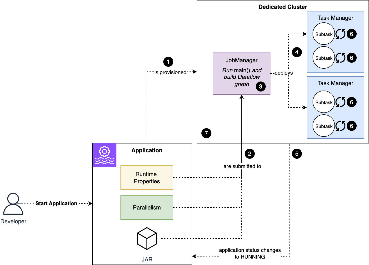
Tag Archives: Amazon Managed Service for Apache Flink

Build a dynamic streaming data lake with Apache Iceberg and Apache Flink

Post Syndicated from Francisco Morillo original https://aws.amazon.com/blogs/big-data/build-a-dynamic-streaming-data-lake-with-apache-iceberg-and-apache-flink/

Handling upstream schema changes is a common operational challenge in streaming data pipelines that write to a data lake. When a source schema changes, teams often face a difficult choice: restart the pipeline or perform a manual migration. A restart can pause ingestion and delay or lose in-flight data. A manual migration consumes engineering time and introduces the risk of schema inconsistencies while the data lake falls behind the source.

For example, consider an Apache Flink job that ingests order_events and writes to an Iceberg table. On Monday, the pipeline runs normally. By Wednesday, the upstream team adds a new loyalty_tier field and introduces a new interaction_events event type. Traditionally, you would need to stop the Flink job, update your schema definitions, and redeploy. With Apache Iceberg’s Dynamic Iceberg Sink on Amazon Managed Service for Apache Flink, the pipeline can handle both changes at the record level without disruption. The DynamicSink routes each event to the right Iceberg table and evolves table schemas as new columns appear, with no operator intervention.

Managed Service for Apache Flink is a fully managed AWS service that you can use to build and deploy streaming applications without setting up infrastructure and managing resources. Apache Flink’s distributed processing engine with exactly once processing guarantees through checkpointing paired with Apache Iceberg’s two-phase commit provides end-to-end consistency without duplications or data loss.

In this post, we show you how to build a dynamic streaming data lake that adapts to new event types and schema changes without stopping the pipeline. Using Apache Flink 2.3 and Apache Iceberg 1.11.0 on Managed Service for Apache Flink, we walk through the DataStream API patterns for per-record table routing and automatic schema evolution. The complete implementation is available in this GitHub repository.

Apache Iceberg dynamic sink

The Dynamic Iceberg Sink allows Flink to dynamically route records to multiple Iceberg tables based on user-defined logic. It also creates and updates tables on the fly and evolves both table schemas and partition specs during streaming execution, controlled through the DynamicRecord class, which eliminates the need for Flink job restarts when requirements change.

Per-record table routing with DynamicIcebergSink

The DynamicIcebergSink resolves the target table at the record level rather than at pipeline configuration time. Records flow through a DynamicRecordGenerator that, for each input, emits one or more DynamicRecord values. Each DynamicRecord carries its own target table ID, schema, partition spec, and row payload, so the sink knows where to write and how the table should look:

DynamicIcebergSink.forInput(events)
    .generator(generator)
    .catalogLoader(catalogLoader)
    .immediateTableUpdate(true)
    .cacheMaxSize(cacheMaxSize)
    .cacheRefreshMs(cacheRefreshMs)
    .append();

The generator receives each record and emits a DynamicRecord targeting a resolved table that looks as follows:

return new DynamicRecord(
    tableId,
    tableBranch,
    icebergSchema,
    rowData,
    partitionSpec,
    distributionMode,
    1);

The sink creates the table if it does not exist and evolves its schema when a record carries new columns. cacheMaxSize and cacheRefreshMs bound the sink’s per-table metadata cache, so a job that writes to many tables does not reload metadata on every record. immediateTableUpdate(true) controls how those catalog changes are applied, which the following section on automatic schema evolution explains. A single Flink job can ingest and route order_events, interaction_events, user_events, and future event types without additional sink definitions.

However, the sink also needs to know what the table looks like. That is why every DynamicRecord also carries the Iceberg schema so that DynamicIcebergSink can create the table on first sight and evolve it as new fields appear. The schema information can be inferred from the data or read from a schema registry.

Automatic schema evolution

Streaming sources add new fields over time, and DynamicIcebergSink handles them without a restart. Before writing each record, it compares the record’s schema against the target table. If the record has a new field, Iceberg adds it as an optional column and commits the change with the next data file. Existing files stay valid and no table rewrite is needed. When you query older files, the new column returns null.

The immediateTableUpdate setting controls where the catalog change happens. The GitHub sample repository sets immediateTableUpdate=true, so the writer subtask that sees the new schema applies the create or alter inline, before it emits the record. This gives the lowest latency but makes more concurrent calls to the catalog. When set to false, records that require a table change take a detour. Records whose table, schema, and partition spec already match the sink’s cached metadata go straight to the writers. Records that do need a change are routed, keyed by table name, to an update operator, so updates for the same table apply one at a time. Once the update commits and the cache refreshes, subsequent records match again and skip the detour. In steady state, with no schema changes arriving, this path adds no extra shuffle. Either way, the schema comparison and the resulting table change are the same.

Schema changes are non-destructive by default. The sink can add new columns, widen existing types (for example, int to long or float to double), relax a required column to optional, and drop columns. Importantly, DynamicIcebergSink does not support renaming columns at the time of writing.

Source schemas are identified in two ways: inferring the schema from source records (for example, JSON inference) and reading serialized records from a schema registry (for example, AWS Glue Schema Registry (GSR)). Schema evolution behavior for the Iceberg sink table depends on the schema source. JSON inference adds any new field it sees, with no contract. For example, this allows the job to initially infer a schema as an integer, and later expand to a long when larger values are detected. Schema registry serialized records define the policy using the registry’s compatibility rules (for example, BACKWARD). This means that incompatible producer changes are rejected when the schema is registered rather than at write time.

The partition spec travels on each DynamicRecord, so the sink applies it when it creates or updates the table. How our sample derives that spec is covered in the partitioning section.

Solution overview

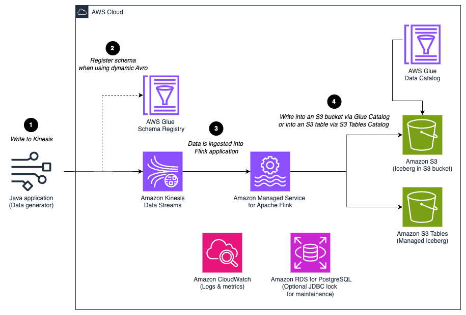
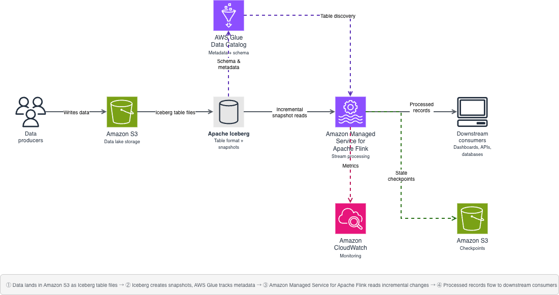
The following diagram illustrates the solution architecture. A data generator (a local Java application) writes events to an Amazon Kinesis Data Stream. In Avro mode it also registers each event schema in the AWS Glue Schema Registry. A Managed Service for Apache Flink application consumes the stream, resolves a target Iceberg table for each record, and writes to Iceberg tables in Amazon S3, cataloged either in the AWS Glue Data Catalog or, for fully managed tables, in Amazon S3 Tables, a capability of Amazon S3.

Data generator sends events to Amazon Kinesis Data Streams, and Managed Service for Apache Flink routes each record to an Iceberg table in Amazon S3

Figure 1: Solution architecture for routing streaming records to per-event Iceberg tables on Managed Service for Apache Flink

At a high level, a single Managed Service for Apache Flink application reads raw records from Kinesis and resolves a target Iceberg table for each record. It uses the DynamicIcebergSink to create and evolve tables on demand. The same job handles many event types because the destination is decided per record, not per sink.

A note on stream topology: the examples assume one Kinesis stream carrying multiple event types, which keeps the walkthrough focused. This is not a requirement for the pattern. If your events arrive on separate streams (for example, one stream per producer or per domain), create one KinesisStreamsSource per stream and union them into a single DataStream before the sink. The routing generator chooses the destination table from the record itself, so many sources can fan into one DynamicIcebergSink and still land in the correct tables.

Unioning does not add shuffle cost. The sink always re-distributes records by an internal per-table writer key, so a unioned stream and N separate pipelines incur the same per-record exchange. The distribution mode each DynamicRecord carries only changes which writer subtask a row lands on, not whether a shuffle occurs. The real tradeoff is isolation. All tables share one writer pool, one commit aggregator, and one committer. A hot stream’s backpressure and checkpoint alignment therefore couple to every other stream, and writer parallelism is a single job-wide setting. Prefer one unioned pipeline when you have many small-to-medium event types that should pool capacity. Split into separate applications when one stream is high-volume enough to need its own writer parallelism and failure isolation.

DynamicIcebergSink needs a schema for every record. The sample provides two interchangeable ways to obtain it, implemented as two generator variants: Option 1 infers the schema from each JSON record at runtime. Option 2 reads the registered schema from AWS Glue Schema Registry. Everything downstream (routing, table creation, and schema evolution) is identical, and only the generator changes.

Option 1: Infer the schema from the JSON record

SchemaAgnosticRoutingGenerator implements Iceberg’s DynamicRecordGenerator. Its generate method maps the routing field to a table name, infers the schema, derives a partition spec, and emits a DynamicRecord through the collector:

@Override
public void generate(JsonNode json, Collector<DynamicRecord> out) {
    String tableName = determineTableName(json); // routing field -> table name
    TableIdentifier tableId = TableIdentifier.of(database, tableName);
    Schema schema = inferSchemaFromJson(json); // cached by schema signature
    RowData rowData = convertJsonToRowData(json, schema);
    PartitionSpec spec = buildPartitionSpec(schema); // cached per schema
    out.collect(new DynamicRecord(
        tableId, "main", schema, rowData, spec, DistributionMode.NONE, 4));
}

The table name comes from an explicit table-name field when present, otherwise from the routing field (event_type by default).

For schemaless or semi-structured JSON, the generator infers an Iceberg schema directly from each record. This is convenient, but inference is fundamentally lossy because JSON does not carry type information. The generator therefore applies deliberately conservative rules and selects a stable type rather than the narrowest one:

JSON value Iceberg type
Integer LongType (all integral values are widened to long)
String StringType
Floating-point values DoubleType
Boolean BooleanType
ISO-8601 timestamps TimestampType (microseconds)
Nested JSON object StructType (with fields inferred recursively)
JSON array ListType (with element type inferred from array contents)

Partitioning the routed tables

Partitioning is decided by our generator, not by the sink, and the same mechanism applies to both schema options: the JSON-inference and schema-registry generators share the partition-candidate logic. The open source DynamicIcebergSink applies whatever PartitionSpec each DynamicRecord carries. Our sample’s SchemaAgnosticRoutingGenerator builds that spec at runtime: it reads a list of candidate partition fields from the partition.candidates application property and derives a per-table spec from the fields it observes. For each table, buildPartitionSpec walks that list and keeps only the candidates present in the table’s schema.

The same list adapts to each table. A table with event_date and region is partitioned by identity(event_date) and identity(region). A table with none of the candidates is created unpartitioned. The resulting spec travels on each DynamicRecord, so the sink applies it when it first creates the table.

For example, with partition.candidates = event_time,region,product: a table whose schema has event_time and product is created partitioned by those two. A table with only event_time gets identity(event_time). A table with none of the candidates is created unpartitioned. Partition specs are not frozen at creation time either: the sink evolves them through Iceberg partition-spec evolution, adding a candidate field when it later appears in the table’s schema and removing one that disappears. This is a metadata-only change, so existing data files keep the spec they were written with.

Two operational practices follow. First, always include your event-time field among the candidates so every table is at least time-partitioned, and monitor for unpartitioned tables through the table’s $partitions metadata or its spec in the catalog: a producer that emits create_timestamp instead of event_time will silently create unpartitioned tables until the candidate list is updated. Second, be deliberate with generic fields like region. If a source produces high-cardinality values for a candidate field, you can correct the spec later. Evolution applies to newly written files only, so the small files already written remain until compaction rewrites them.

Note that the candidate list is global, not per table. It tracks every field you might partition on, and each table takes only the ones it has.

Option 2: Read the schema from a schema registry

Inference is convenient but lossy, and it offers no contract: nothing stops a producer from silently changing a field’s type or meaning. The second option removes the guesswork by reading the schema from a registry instead of the data. Many production streaming platforms standardize on strongly typed Avro schemas managed through AWS Glue Schema Registry. With GSR, producers register schemas explicitly, each record on Kinesis is Avro-encoded and prefixed with a schema-version ID, and the consumer decodes against the exact registered schema. That gives you three things JSON inference cannot: precise types (a long stays a long, a timestamp-micros stays a timestamp-micros), a governed evolution policy enforced at registration, and a single source of truth shared across producers and consumers.

The pattern works with any schema registry that gives consumers the writer’s schema per record. The sample implements it with AWS Glue Schema Registry, but the same generator shape applies to other registries.

The dynamic-sink-avro-sample module applies GSR-managed Avro schemas to the same dynamic routing and schema evolution pattern. For each record, AvroToDynamicRecordGenerator reads the schema-version ID and fetches the writer schema from GSR, caching it after the first lookup. It then converts that schema to an Iceberg schema, decodes the payload into RowData, and emits a DynamicRecord, exactly as the JSON generator does:

The sink wiring is identical to option 1. Only the generator changes, and because the source carries raw Avro bytes the input stream is byte[] rather than parsed JSON:

AvroToDynamicRecordGenerator generator = new AvroToDynamicRecordGenerator(
    awsRegion, registryName, database, partitionCandidates, branch);
DynamicIcebergSink.forInput(eventBytes)
    .generator(generator)
    // identical catalogLoader, immediateTableUpdate(true), cache, and write settings as option 1
    .append();

Because the schema comes from GSR rather than from inspecting bytes, the Avro-to-Iceberg type mapping is exact:

Category Avro type Iceberg type
Primitive int IntegerType
Primitive long LongType
Primitive float FloatType
Primitive double DoubleType
Primitive string StringType
Primitive boolean BooleanType
Logical timestamp-millis TimestampType (preserves millisecond precision)
Logical timestamp-micros TimestampType (preserves microsecond precision)
Logical decimal DecimalType
Complex record StructType (nested fields mapped recursively)
Complex array ListType (element type inferred from items schema)
Complex map MapType (keys are always StringType)

The GSR integration handles schema versioning transparently. As soon as a producer registers a new schema version containing additional fields, the Flink consumer deserializes the updated payload and evolves the Iceberg table to match, with no job restart.

Prerequisites

To follow along, you need the following:

  • An AWS account with permissions to create Amazon Kinesis Data Streams, Managed Service for Apache Flink applications, AWS Glue resources, and Amazon S3 buckets (plus Amazon S3 Tables if you choose that catalog).
  • The AWS Command Line Interface (AWS CLI) configured with credentials.
  • Node.js 18 or later and the AWS Cloud Development Kit (AWS CDK) CLI.
  • Java 17 or later and Apache Maven 3.9 or later, to build the data generator.
  • Docker running locally. The CDK build bundles the Flink application jars inside a Maven image.

Deploy and test the solution

The accompanying repository provisions everything through a single parameterized AWS CDK stack.

  1. Install the CDK dependencies and bootstrap your environment (first time only):
    cd cdk-infrastructure && npm install
    npx cdk bootstrap aws://<account>/<region>

  2. Deploy the variant you want to try:
    npx cdk deploy -c appType=dynamic -c tableFormatVersion=2 # JSON inference variant
    npx cdk deploy -c appType=dynamic-avro -c tableFormatVersion=2 # GSR Avro variant

    Add -c catalogType=s3tables to either command to use Amazon S3 Tables instead of the AWS Glue Data Catalog. The walkthrough sets tableFormatVersion=2 so you can query the results with a broad range of engines. Omit it to use the default, Iceberg format version 3, when you query with a v3-aware engine such as Spark on Amazon EMR 7.12+ or AWS Glue ETL.

  3. Start the application using the ApplicationName value from the stack outputs:
    aws kinesisanalyticsv2 start-application --application-name <ApplicationName> --run-configuration 'ApplicationRestoreConfiguration={ApplicationRestoreType=SKIP_RESTORE_FROM_SNAPSHOT}'

  4. Send test events with the included data generator. Start with the v1 payloads, which create the tables without the optional fields:
    java -jar data-generator/target/data-generator-1.0-SNAPSHOT.jar <stream-name> <region> 100 60 v1

    Then send v2 payloads, which add the userAgent and scrollDepth fields. This second run is the schema evolution you observe in the next step:

    java -jar data-generator/target/data-generator-1.0-SNAPSHOT.jar <stream-name> <region> 100 60 v2

    For the Avro variant, the generator registers each schema version in the AWS Glue Schema Registry as it sends:

    java -jar data-generator/target/data-generator-1.0-SNAPSHOT.jar avro <stream-name> <region> <registry-name> 100 60

  5. Query the routed tables in Amazon Athena. You should see one Iceberg table per event type appear in the database within a checkpoint interval, and after sending v2 events, the new fields (userAgent, scrollDepth) show up as optional columns on the same tables. The Iceberg metadata tables (for example, SELECT * FROM "db"."table$snapshots") show each commit the sink makes.

Clean up

When you finish testing, delete the resources to stop incurring charges:

cd cdk-infrastructure && npx cdk destroy

CDK removes the Kinesis Data Stream, the Managed Service for Apache Flink application, and the stack-created AWS Identity and Access Management (IAM) roles. Additionally, empty and delete the S3 warehouse bucket to remove the Iceberg data and metadata files, delete any schemas the Avro variant registered in the AWS Glue Schema Registry, and delete the table bucket contents if you used the S3 Tables catalog.

Conclusion

With Apache Iceberg 1.11.0 and Flink 2.3, you can build streaming data lake architectures that adapt to change without stopping the pipeline. With per-record routing, a single Flink application can write multiple event types to separate Iceberg tables, while automatic schema evolution keeps table definitions aligned with changing source data. Choosing AWS Glue Schema Registry over runtime JSON inference adds precise types and a governed evolution contract, and a configurable partition-candidate list keeps each routed table partitioned correctly without pre-declaring its schema.

The result is fewer pipeline redeployments, reduced operational overhead, and a data lake that remains synchronized with evolving application schemas.

To get started, follow the deploy and test section, then adapt the routing field and partition candidates to your own event types.

The full sample code is available in the accompanying GitHub repository.


About the authors

Francisco Morillo

Francisco Morillo

Francisco is a Sr. Streaming Solutions Architect at AWS, specializing in real-time analytics architectures. With over five years in the streaming data space, Francisco has worked as a data analyst for startups and as a big data engineer for consultancies, building streaming data pipelines. He has deep expertise in Amazon Managed Streaming for Apache Kafka (Amazon MSK) and Amazon Managed Service for Apache Flink.

Felix John

Felix John

Felix is a Global Solutions Architect and data & AI expert at AWS, based out of Germany. He focuses on supporting AWS’ strategic global automotive & manufacturing customers on their data & AI transformation journey.

How Buildkite Operates Test Analytics at Massive Scale with Amazon MSK and Amazon Managed Service for Apache Flink

Post Syndicated from James Hill original https://aws.amazon.com/blogs/big-data/how-buildkite-operates-test-analytics-at-massive-scale-with-amazon-msk-and-amazon-managed-service-for-apache-flink/

When engineering teams at Slack, Reddit, Canva, Airbnb, Shopify, and Uber need to ship code with confidence, they rely on Buildkite. As a CI/CD platform, Buildkite orchestrates complex build, test, and deployment pipelines for some of the most demanding engineering organizations in the world. It handles everything from routine code commits to artificial intelligence (AI) model-training workloads, processing over 50 billion requests per month.

At the heart of Buildkite’s test orchestration portfolio is Test Engine, a specialized analytics product designed to help engineering teams understand and optimize their test suites at scale. Test Engine aggregates results across thousands of builds, flags flaky tests, runs parallel test execution across machine fleets, and delivers interactive analytics on test execution data. It supports arbitrary metadata tagging for dimensions like instance type, architecture, language version, cloud provider, and feature flags.

The challenge? Delivering all of this in real time, across multiple enterprise tenants, at a volume that would stress even the most robust data infrastructure. In this post, we explore how Buildkite uses Amazon Managed Streaming for Apache Kafka (Amazon MSK) and Amazon Managed Service for Apache Flink to power Test Engine’s streaming-first analytics architecture at scale.

The problem: When scale breaks traditional architectures

Buildkite’s Test Engine must ingest and serve analytics on test telemetry from thousands of distributed pipelines simultaneously, for multiple enterprise customers. The scale is unforgiving: 50 billion test executions per month, 500K events per second at peak ingestion, and webhook payloads reaching 21 MB.

The architectural evolution and its limits

The original Rails and PostgreSQL stack couldn’t sustain this growth. In 2024, the team re-architected around a distributed streaming layer, a stateful stream processor for pre-aggregations, and multiple specialized stores: a key-value store for fast lookups, a relational database for pre-computed aggregates, and an open table format (Iceberg) with a distributed query engine (Trino) for flexible querying.

Yet the core tension remained unsolved. Enterprise customers demanded interactive, arbitrary slicing of billions of records across high-cardinality dimensions, not canned reports. The stream processor couldn’t handle ad hoc aggregations at query time. The key-value store was blind to analytical queries. The distributed query engine offered flexibility but was too slow for interactive use.

The result was a system that was expensive and operationally complex. It included nine relational database clusters, sprawling ETL pipelines, and 24/7 pre-aggregation jobs running regardless of demand. It still couldn’t deliver the one thing customers needed most: fast, flexible, interactive analytics at scale.

Architecture and implementation: MSK and Amazon Managed Service for Apache Flink as the streaming backbone

The solution Buildkite arrived at centers on Amazon Managed Streaming for Apache Kafka (Amazon MSK) and Amazon Managed Service for Apache Flink as the real-time data streaming and processing layers, decoupling high-throughput ingestion from downstream analytics.

The data pipeline

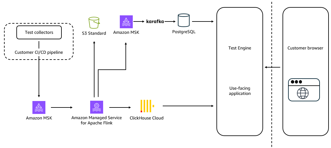
The following diagram shows the end-to-end data flow from CI/CD agents through Amazon MSK and Amazon Managed Service for Apache Flink to the analytics layer.

Architecture diagram showing the Buildkite data pipeline from CI/CD agents through Amazon MSK and Amazon Managed Service for Apache Flink to ClickHouse analytics

Amazon MSK sits at the critical junction between data producers (the distributed CI/CD agents and test collectors running across customer infrastructure) and the downstream processing and analytics layers. Amazon Managed Service for Apache Flink then transforms those raw event streams into enriched, queryable data before it reaches the analytics store.

High-throughput ingestion from CI/CD pipelines

Amazon MSK’s role begins at ingestion. Test collectors embedded in CI/CD pipelines publish test execution events directly to Kafka topics. The existing Amazon MSK cluster handles between 5 MB/sec and 100 MB/sec of inbound data under normal operating conditions. The architecture is designed to absorb the significant variance inherent in CI/CD workloads, where pipeline activity is bursty and correlated with engineering team working hours across global time zones.

When the Buildkite project was initiated, MSK Express Brokers were not yet available, leading the team to adopt MSK Tiered Storage as the primary mechanism for scaling and recovery. With MSK Express Brokers now generally available, the team is evaluating a migration of its most critical log ingestion workload, which sustains up to 1 GB/s at peak ingestion. MSK Express Brokers bring automatic storage scaling with zero storage management overhead, up to 20x faster scaling and 90% faster broker recovery, 3x higher per-broker throughput, 5x more partitions per broker, and built-in Intelligent Rebalancing.

Real-time stream processing with Amazon Managed Service for Apache Flink

Sitting between Amazon MSK and the analytics layer, Amazon Managed Service for Apache Flink acts as the stateful stream processing engine that transforms raw event streams before they reach downstream systems. Buildkite selected Flink for its exactly-once processing, mature stateful computation model, and deep Kafka integration. Handling sustained peaks of over 25,000 events per second, Amazon Managed Service for Apache Flink eliminates the operational overhead of cluster provisioning, version upgrades, checkpointing, and job recovery. This frees engineering teams to focus on application logic.

Amazon Managed Service for Apache Flink powers key stateful processing tasks, including flaky test detection through time-windowed pattern matching, enriching execution events with pipeline and customer metadata, and routing processed data to downstream systems such as ClickHouse for analytics, PostgreSQL for operational workloads, and Amazon Simple Storage Service (Amazon S3) for long-term archival.

Reliability and fault tolerance

Amazon MSK’s three-replica configuration ensures that no single broker failure can cause data loss or ingestion interruption. Combined with flexible data retention, the architecture provides a meaningful replay window. If a downstream consumer (Amazon Managed Service for Apache Flink, ClickHouse, or another service) experiences an outage, it can resume processing from its last committed offset without data loss.

During the migration to the current architecture, Buildkite employed a dual-write strategy: simultaneously writing to both the existing PostgreSQL pipeline and the new Amazon MSK/ClickHouse path. This approach allowed the team to validate data consistency and gradually shift traffic without risking customer-facing disruption. This pattern speaks to the operational maturity Amazon MSK provides.

Operational efficiency gains

The shift to a streaming-first architecture, combined with the downstream simplification of the analytics engine, produced significant operational improvements:

  • Flink workloads reduced by 60%+: Eliminating pre-aggregation jobs that ran continuously regardless of demand.
  • Key/value store completely retired: Amazon MSK’s buffering capability, combined with ClickHouse’s query performance, eliminated the need for a separate fast-lookup store.
  • PostgreSQL capacity cut in half: Nine separate database clusters consolidated and right-sized.
  • Thousands of lines of application code deleted: Simpler architecture means less ETL code, fewer failure modes, and faster onboarding for new engineers.

Platform performance at a glance

Metric Value
Monthly test executions (for test engine platform) 50 billion (4x growth from 3B)
Sustained peak ingestion 500K events/second
Total records in analytics store 200 billion
Log ingestion requests 70,000+ per second
Peak webhook throughput 1.7 GB/second
MSK inbound throughput range 5 MB/sec – 100 MB/sec

Business and developer impact

The technical architecture ultimately exists to serve one purpose: helping developers ship better software faster. The streaming-first architecture built on Amazon MSK and Amazon Managed Service for Apache Flink delivers on that promise across four dimensions.

On-demand analytics replaced pre-computed reports. Customers can now interactively slice and dice 70 billion records across arbitrary metadata dimensions. They get answers to queries like “Show me P50 test durations by instance type and architecture for the last 30 days” in seconds, not hours. Real-time log streaming through the “live tail” feature means developers no longer wait for a build to complete before diagnosing failures. At 25,000 events per second, this experience scales across thousands of concurrent enterprise pipelines without degradation.

Smarter test intelligence comes from Amazon Managed Service for Apache Flink’s stateful flaky test detection: when a test begins exhibiting intermittent failure patterns, Amazon Managed Service for Apache Flink identifies it as it happens, not after the fact. This is what separates a proactive analytics platform from a reactive one. It requires publishing data to Kafka, processing with Flink, and letting ClickHouse handle the complex read requests.

Conclusion: Streaming as a strategic foundation

Buildkite’s journey from a Rails/Postgres monolith to a streaming-first analytics platform reflects a pattern increasingly common among enterprise SaaS companies: a reliable, high-throughput streaming and processing layer is not an optimization. It is a prerequisite for operating at scale.

Amazon MSK and Amazon Managed Service for Apache Flink form the backbone that helps Buildkite ingest 50 billion test executions per month, serve real-time interactive analytics to enterprise customers, and do so at lower cost than the more complex architecture it replaced. Amazon MSK handles durable, elastic event buffering. Amazon Managed Service for Apache Flink transforms raw streams into enriched, queryable data. Together they absorb the operational complexity that would otherwise consume engineering capacity.

For platform engineers evaluating streaming infrastructure for multi-tenant SaaS workloads, the signal is clear: invest in the streaming backbone early, and let managed services handle the operational complexity.

To learn more about Amazon MSK and Amazon Managed Service for Apache Flink, visit aws.amazon.com/msk and aws.amazon.com/managed-service-apache-flink.


About the authors

James Hill

James Hill

James has been building and scaling software systems for more than 25 years, from early web applications to platforms that now process millions of builds every day. Starting his career as a software engineer, James has led teams across Australia, the UK, and globally, solving problems in performance, reliability, and delivery speed at massive scale. Today, he works with some of the world’s largest engineering organizations to help them ship faster and with greater confidence, drawing on deep, hands-on experience in both engineering and product leadership. James is passionate about turning testing from a bottleneck into a feedback engine that accelerates learning across an organization.

Mitch James

Mitch James

Mitch is a Brand and Marketing Strategist with deep expertise crafting end-to-end brand experiences and fostering engaged communities around technical tooling. He brings 15+ years of Brand, Design, and Marketing leadership across devtools, consumer product, and B2B enterprise. Previously, Mitch has built and led creative teams at Adobe, IBM, Salesforce, George P Johnson, Wunderman Thompson, and VML. Today, he leads global marketing and design for Buildkite, working with engineering teams who set the pace at the frontier of software delivery.

Masudur Rahaman Sayem

Masudur Rahaman Sayem

Masudur is a Streaming Data Architect at AWS with over 25 years of experience in the IT industry. He collaborates with AWS customers worldwide to architect and implement data streaming solutions that address complex business challenges. As an expert in distributed computing, Sayem specializes in designing large-scale distributed systems architecture for maximum performance and scalability. He has a keen interest and passion for distributed architecture, which he applies to designing production-ready solutions at internet scale.

Miranda Li

Miranda Li

Miranda is a Senior Solutions Architect at AWS, specializing in Independent Software Vendor (ISV) and cloud-native architectures. With four years dedicated to helping software partners innovate and scale on AWS, she focuses on helping ISVs build and optimize their solutions for the cloud. She brings deep technical expertise in cloud infrastructure and data analytics, with a strong focus on supporting technical customers in areas such as Infrastructure as a Service (IaaS), network architecture, and security. Outside of work, she is an avid badminton player and enjoys staying active through jogging and outdoor adventures.

How Smartsheet built Real-time Dynamic Filtering on Apache Flink reducing $40K/month in messaging costs

Post Syndicated from Emre Kartoglu original https://aws.amazon.com/blogs/big-data/how-smartsheet-built-real-time-dynamic-filtering-on-apache-flink-reducing-40k-month-in-messaging-costs/

Processing hundreds of thousands of events per second while maintaining sub-second latency is a challenge many organizations face when building real-time data-driven applications. When filter policy changes propagate in up to 15 minutes, dynamic event routing becomes impractical, forcing teams to over-consume events and discard over 90% after costly per-event lookups. Smartsheet, a work management solution serving millions of users and processing hundreds of thousands of events per second to power features like live collaboration, workflows, and real-time notifications, faced exactly this problem.

In this post, you learn how Smartsheet built a Real-time Dynamic Filtering (RDF) system on Amazon Managed Service for Apache Flink, cutting messaging costs by over $40,000 per month and improving live collaboration latency by 1.8x.

The challenge: Static filter policies in a dynamic world

The Smartsheet event-driven architecture publishes hundreds of thousands of events per second to an Amazon Simple Notification Service (Amazon SNS) topic. Internal teams subscribe to this topic, typically by creating an Amazon Simple Queue Service (Amazon SQS) queue with an associated SNS filter policy defined through infrastructure as code (IaC). These filter policies are typically static and specify the types of events a consumer wants to receive, such as “sheet row created,” “sheet row updated,” or “sheet row deleted.”

Although SNS supports programmatic changes to filter policies, the SNS documentation notes that changes can take up to 15 minutes to take effect. This eventual consistency window created a significant problem for Smartsheet live collaboration feature.

Live collaboration requires knowing, in real time, which sheets have active collaborators. When a user opens a sheet, the system needs to immediately start receiving events for that sheet. When they close it, the system should stop. With a 15-minute propagation delay on filter policy changes, dynamic per-sheet filtering through SNS was impractical.

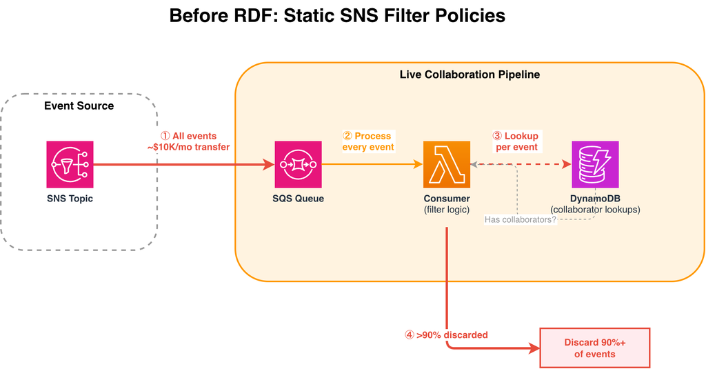
The workaround was brute force: subscribe to all events (hundreds of thousands per second), pull them into an SQS queue, and use compute to check each event against Amazon DynamoDB to determine whether the sheet had active collaborators. Over 90% of events were discarded after this lookup.

Architecture diagram showing events flowing from SNS to SQS with per-event DynamoDB lookups before RDF

Figure 1: Before RDF — all events flow through SNS to SQS, with per-event DynamoDB lookups to filter. Over 90% of events are discarded after processing.

  1. Every event published to the SNS topic is delivered to the SQS queue, regardless of whether any consumer needs it.
  2. The consumer AWS Lambda reads every message from the SQS queue and must evaluate each one individually.
  3. For each event, the consumer queries DynamoDB to check whether the sheet has active collaborators. This per-event lookup adds latency and DynamoDB read costs on the hot path.
  4. After the DynamoDB lookup, over 90% of events are found to have no active collaborators and are discarded.

This approach had three compounding cost and performance problems:

  • SNS-to-SQS data transfer costs: approximately $10,000 per month to deliver all events to the queue
  • SQS costs: approximately $30,000 per month to receive, process, and delete the full event volume
  • DynamoDB costs and latency: per-event lookups to check collaborator status added load to DynamoDB and increased end-to-end data delivery latency

The solution: Real-time Dynamic Filtering with Apache Flink

To solve this, Smartsheet built a system called Real-time Dynamic Filtering (RDF) on Amazon Managed Service for Apache Flink. The core insight was to move the filtering logic into the stream processing layer itself, using Flink’s KeyedCoProcessFunction, a feature that joins and processes multiple streams by a shared key, to maintain dynamic filter policies in Flink state (RocksDB).

How it works

The RDF Flink application reads from two streams:

  1. Filter policy stream, sourced from Amazon DynamoDB Streams. When a team calls the RDF client to change their filter policy (for example, “start receiving events for sheet X”), the change is written to a DynamoDB table and propagated through DynamoDB Streams to the Flink application.
  2. Data stream, the stream of sheet events (creates, updates, deletes) that were previously delivered through SNS.

One challenge remained: some consumers need every event, regardless of sheet. When a consumer subscribes to all events, the system needs every parallel Flink task to know about it. The team solved this using Flink’s broadcast state, which replicates a small set of “subscribe to everything” policies across all tasks. Because only a handful of consumers use this mode, the memory overhead stays negligible.

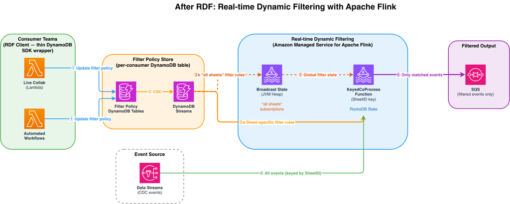
Architecture diagram showing the RDF system with DynamoDB Streams feeding filter policies to the Flink application

Figure 2: After RDF — consumer teams update filter policies via client libraries. DynamoDB Streams propagates changes to the Flink application, which filters the data stream in real time using keyed state (RocksDB) for specific sheet subscriptions and broadcast state for “all sheets” subscriptions.

  1. When a consumer team wants to start or stop receiving events for a specific sheet, it calls the RDF client, a thin wrapper over the DynamoDB SDK. The filter policy change is written to that consumer’s dedicated DynamoDB table. Each consumer has its own table, providing isolated permissions and preventing noisy neighbor issues.
  2. DynamoDB Streams captures every filter policy change as a change data capture (CDC) record and streams it to the Flink application in real time.
  3. Filter policy records
    1. Filter policy records for specific sheets are routed to the KeyedCoProcessFunction, keyed by SheetID. This makes sure that filter state and event data for the same sheet are co-located in the same Flink parallel task. State is stored in the RocksDB backend, which uses memory when available and spills to disk when necessary, so the system to scale without JVM heap constraints.
    2. Filter policy records where a consumer has called listenToAllEvents() are broadcast to all parallel Flink tasks via Flink’s broadcast state. Because broadcast state lives in JVM heap, it is used exclusively for these “all sheets” records (of which there are very few), keeping the heap footprint small.
  4. The full stream of CDC events flows into the KeyedCoProcessFunction, partitioned by SheetID. Each parallel task receives only the events for the sheets it is responsible for and applies the corresponding filter state to decide whether to forward or drop each event.
  5. The broadcast state (containing “all sheets” subscriptions) is made available to all parallel instances of the KeyedCoProcessFunction, so that consumers subscribed to all events are never filtered out regardless of which task processes their events.
  6. Only events that match an active filter policy are forwarded to the consumer’s SQS queue. The result: sub-second filter policy propagation (p95 ≤1s), elimination of per-event DynamoDB lookups, and over $40,000/month in cost savings.

Critically, because the filter policy state is persisted in Flink’s RocksDB state backend, the application does not need to perform a DynamoDB lookup for every event. Within 1 second of a filter policy change, the Flink application reads the change from the DynamoDB Streams source, updates its internal state, and begins filtering the data stream accordingly.

Results

The impact of RDF was immediate and measurable across multiple dimensions:

Cost reduction

Cost category Before RDF After RDF Monthly savings
SNS → SQS Data Transfer ~$10K/month Eliminated ~$10K
SQS Event Ingestion ~$30K/month ~$2K ~$28K
DynamoDB Collaborator Lookups Significant load Eliminated (state in Flink) Included in total
AWS Lambda ~$12K/month ~$5K/month ~$7K
Total ~$45K/month

Latency improvement

  • 1.8x improvement in live collaboration data delivery latency. Users see changes from collaborators faster than before.
  • Filter policy propagation reduced from up to 15 minutes to a p95 of under 1 second

If your architecture follows a similar fan-out pattern where consumers discard a large percentage of events after per-event lookups, you could achieve comparable cost reductions by moving filtering into the stream processing layer. The savings scale with your event volume and the percentage of events currently discarded.

Key design decisions

Several architectural choices were critical to the success of this solution:

  1. Keyed state with selective broadcast: Specific sheet subscriptions are stored in keyed state using the RocksDB state backend. The system scales to a large number of filter policies without JVM heap constraints. Flink’s broadcast state is used only for the small number of “all sheets” subscriptions, where every parallel task needs visibility. Because broadcast state is stored in JVM heap, limiting its use to these few records keeps the heap footprint manageable.
  2. DynamoDB Streams as the filter policy source: Rather than building a custom control plane, the team used DynamoDB Streams to propagate filter policy changes. DynamoDB Streams gave the team durability, ordering guarantees, and a native Flink source connector integration.
  3. RocksDB state backend: Persisting filter state in RocksDB eliminated the need for external lookups on the hot path, keeping per-event processing latency low even as the number of active filter policies grows.
  4. Client library abstraction: Publishing internal Golang and Java clients lowered the adoption barrier. The client is a thin abstraction on top of the DynamoDB SDK. Each consumer has its own dedicated DynamoDB table and corresponding filter stream, which provides two benefits: it allows fine-grained AWS Identity and Access Management (AWS IAM) permissions per client, and it mitigates the noisy neighbor problem by isolating each consumer’s filter policy traffic. Teams don’t need to understand Flink internals. They interact with a simple API to manage their subscriptions.

Next steps

The live collaboration team was the first adopter of RDF, but the architecture was designed as a shared platform. Smartsheet is now expanding RDF to additional internal teams, including workflow automation and notification routing, where similar fan-out patterns exist. The team is also exploring automatic scaling policies to optimize Flink cluster costs during off-peak hours.

Conclusion

Smartsheet Real-time Dynamic Filtering system demonstrates how Amazon Managed Service for Apache Flink can solve problems that go beyond stream processing. By combining Flink’s broadcast state pattern with CoProcessFunction, Smartsheet replaced a costly and latency-bound SNS/SQS fan-out architecture with a sub-second dynamic filtering platform. The result: over $40,000 per month in savings, 1.8x improvement in live collaboration latency, and a reusable platform that multiple teams are now adopting.

If you process high-volume event streams and need to dynamically control which events reach specific consumers, this pattern can help you reduce costs and latency, whether for live collaboration, workflow automation, notification routing, or multi-tenant event delivery.

To learn more about the services used in this post, visit:


About the authors

Emre Kartoglu

Emre is a Principal Engineer at Smartsheet, where he led the adoption of Apache Flink to power features such as sheet history, live collaboration, and automations. Previously a software engineer at AWS helping build Amazon Managed Service for Apache Flink, he is an active open-source contributor to the Apache Flink project, including FLIP-418 for data skew calculation and visualization and the AWS connectors for Apache Flink. He is based in London, UK, and is passionate about operational excellence, building products, establishing mechanisms, and using data to drive positive culture change.

Rony Blum

Rony Blum

Rony Blum is a Senior Solutions Architect at AWS based in Seattle, working with ISV customers to design and implement advanced cloud architectures, specializing in SaaS solutions, multi-tenant systems, and Generative AI applications. Outside of work, Rony enjoys exploring the Pacific Northwest trails on foot and hitting the slopes during ski season.

Francisco Morillo

Francisco Morillo

Francisco Morillo is a Sr. Streaming Solutions Architect at AWS, specializing in real-time analytics architectures. With over five years in the streaming data space, Francisco has worked as a data analyst for startups and as a big data engineer for consultancies, building streaming data pipelines. He has deep expertise in Amazon Managed Streaming for Apache Kafka (Amazon MSK) and Amazon Managed Service for Apache Flink.

Build streaming applications on Amazon Managed Service for Apache Flink with AI-assisted guidance

Post Syndicated from Mazrim Mehrtens original https://aws.amazon.com/blogs/big-data/build-streaming-applications-on-amazon-managed-service-for-apache-flink-with-ai-assisted-guidance/

Building production-ready Apache Flink applications requires learning a complex ecosystem. The learning curve is steep for newcomers, and even experienced Flink developers encounter complexity when scaling applications or troubleshooting production issues. With the new Kiro Power and Agent Skill for Amazon Managed Service for Apache Flink, you can get AI-assisted guidance for building, improving, and migrating streaming applications directly in your development environment, with recommendations that are grounded in best practices.

The Managed Service for Apache Flink Kiro Power and Agent Skill helps you navigate challenges across the Flink application lifecycle. For new development, the tool provides contextual guidance on application architecture, state management patterns, and connector selection. For existing application improvements, it analyzes your existing code to identify performance bottlenecks, reliability risks, and opportunities for improvement. If you’re upgrading from Apache Flink 1.x to 2.x, it detects compatibility issues and provides targeted refactoring steps to modernize your applications.

In this post, we walk through installing the Power and Skill, using Amazon Kinesis Data Streams to build a Kinesis Data Stream-to-Kinesis Data Stream streaming pipeline, and migrating an existing application to Flink 2.2. You can follow along with this use case to see how the Managed Service for Apache Flink Kiro Power can help you build a resilient, performant application grounded in best practices.

Solution overview

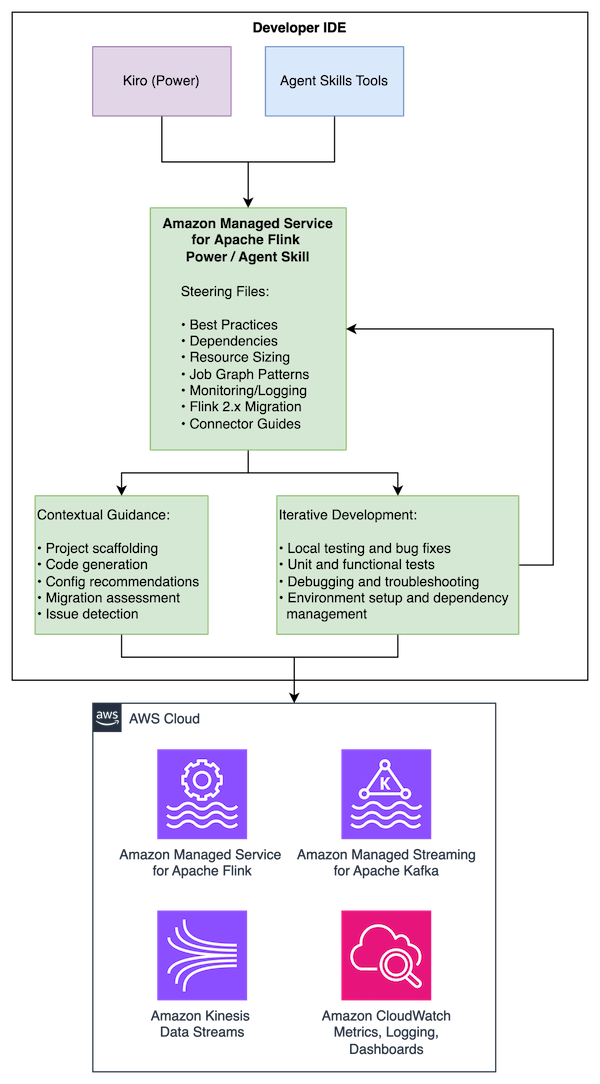
The Managed Service for Apache Flink Power/Skill works across multiple AI development tools, providing the same comprehensive guidance in each:

  • Kiro: Installs as a Power that automatically activates for Flink-related development activities
  • Cursor and Claude Code: Installs as an Agent Skill following the open Agent Skills standard
  • Other compatible agents: Compatible with tools supporting the Agent Skills specification

The Power/Skill provides guidance across the development lifecycle:

  • Best practices for Managed Service for Apache Flink application development
  • Maven dependency management and project structure
  • Resource improvements including KPU sizing, parallelism tuning, and checkpointing
  • Job graph architecture patterns and anti-patterns
  • Amazon CloudWatch monitoring and logging configuration
  • Flink 1.x to 2.2 migration guidance with state compatibility assessment
  • Connector-specific guidelines

The content is maintained in a single repository with use case specific entry points that are dynamically loaded depending on your needs.

Prerequisites

To use the tool, you need:

  • A development machine running macOS, Linux, or Windows with Java 11 or later (Java 17 for Flink 2.2) and Apache Maven installed
  • One of the following AI development tools:
    • Kiro IDE
    • Cursor
    • Claude Code
    • Other Agent Skills-compatible tools
  • Basic knowledge of Java and stream processing concepts (helpful but not required)
  • An AWS Identity and Access Management (IAM) role configured with access to create and run Managed Service for Apache Flink applications, create Amazon Simple Storage Service (Amazon S3) buckets for Flink application dependencies, create Kinesis Data Streams for streaming, and create IAM roles (required if deploying an application)

Installation

Installing as a Kiro Power

  1. Open Kiro IDE.
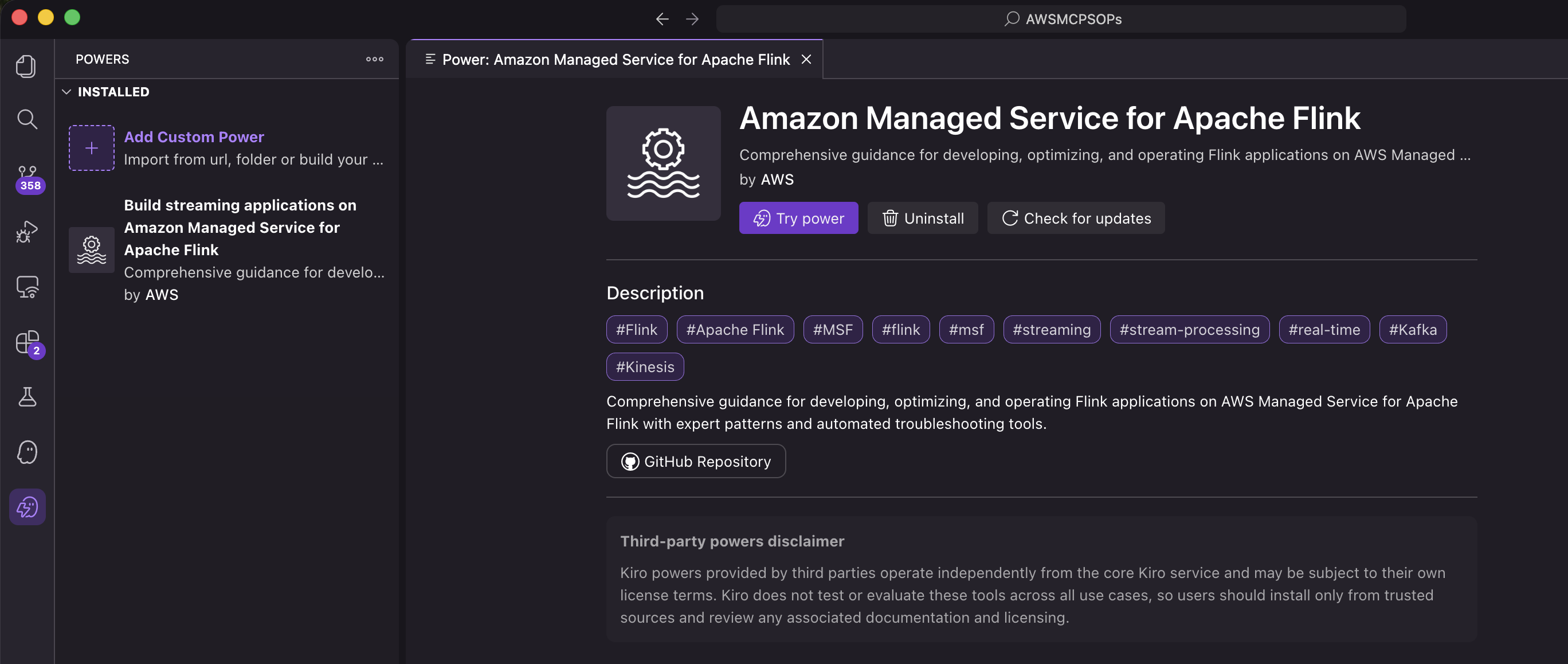
  2. Open Amazon Managed Service for Apache Flink and select Open in Kiro.

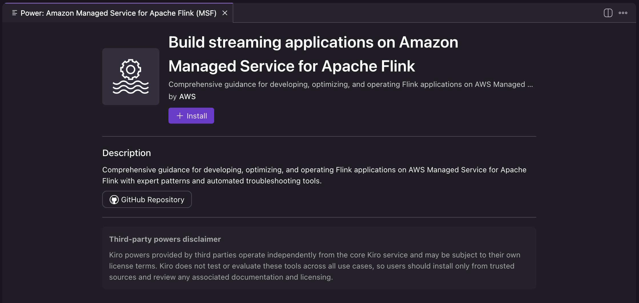
  1. Choose Install to install the power.

  1. Verify that the power is listed in the installed powers in the Kiro IDE.

The Power is now installed and automatically activates when you work on Flink-related development activities.

Installing as an Agent Skill

Agent Skills are discovered automatically by compatible tools through the SKILL.md file. Installation varies by tool:

Per-project installation (available in one project):

# For Cursor
git clone https://github.com/awslabs/managed-service-for-apache-flink-agent-steering-files.git .cursor/skills/flink

# For Claude Code
git clone https://github.com/awslabs/managed-service-for-apache-flink-agent-steering-files.git .claude/skills/flink

# For other Agent Skills-compatible tools
git clone https://github.com/awslabs/managed-service-for-apache-flink-agent-steering-files.git .agents/skills/flink

Personal installation (available across projects):

# For Cursor
git clone https://github.com/awslabs/managed-service-for-apache-flink-agent-steering-files.git ~/.cursor/skills/flink

# For Claude Code
git clone https://github.com/awslabs/managed-service-for-apache-flink-agent-steering-files.git ~/.claude/skills/flink

To verify the installation, interact with the skill in your preferred tool. In Claude Code, you can invoke it with /flink. In Cursor, type / in Agent chat and search for flink. For more information about Agent Skills, see the Agent Skills documentation.

Example: Building a Kinesis-to-Kinesis streaming pipeline

Rather than listing best practices, the Power/Skill actively guides you through making the right architectural decisions at each stage of development.

The following walkthrough demonstrates building a Flink application that reads from Amazon Kinesis Data Streams, analyzes events, and writes to another Kinesis stream. To follow along, run the same prompts in your Kiro IDE or other development tool. In the following prompts, we focus on local development and don’t create AWS resources. However, if you prompt the agent to create and deploy AWS resources, they will incur additional costs.

Starting the conversation

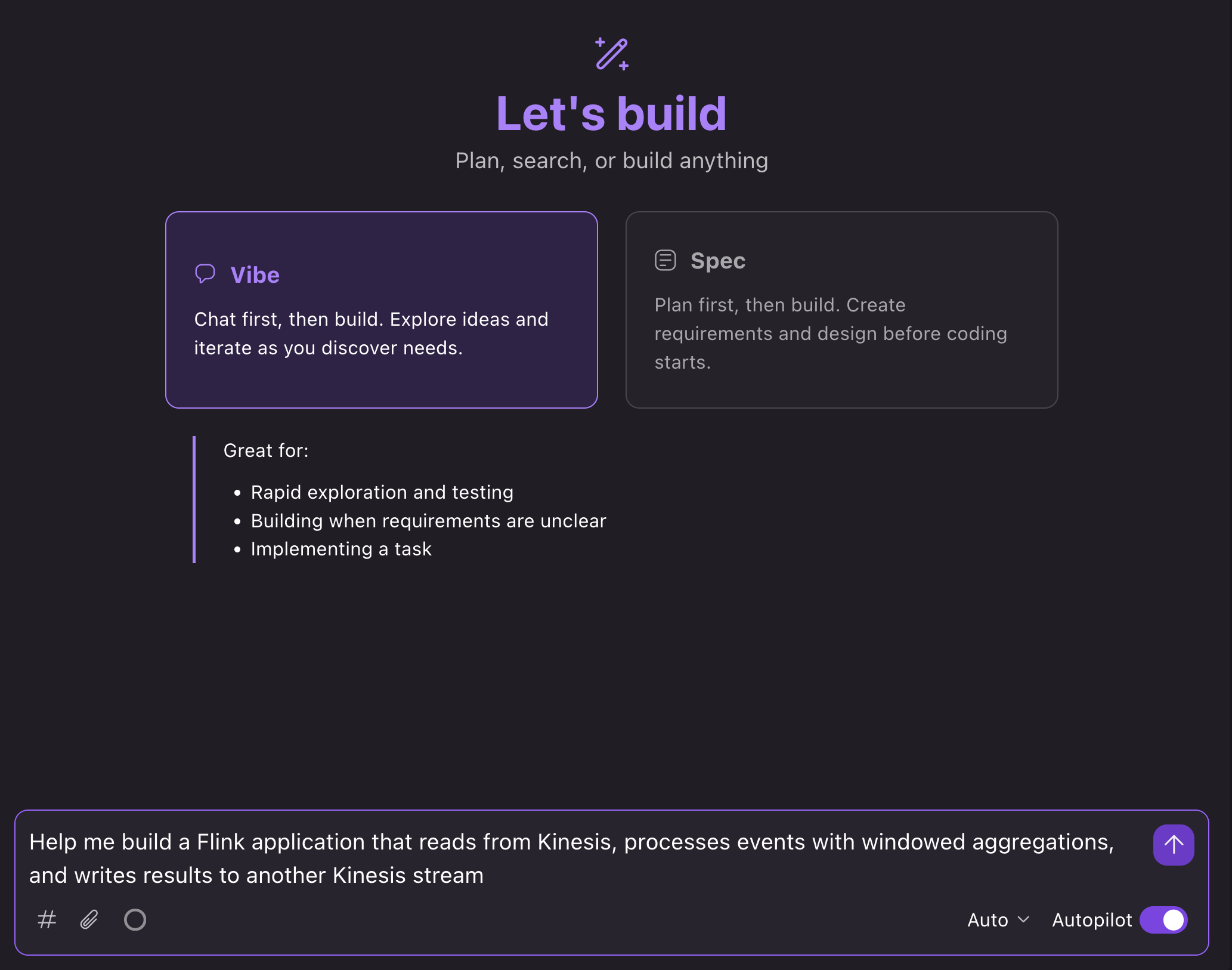
In the Kiro IDE, we can open a new chat in Vibe mode and prompt: “Help me build a Flink application that reads from Kinesis, processes events with windowed aggregations, and writes results to another Kinesis stream”:

Kiro chat showing a prompt to build a Kinesis streaming application

What happens next

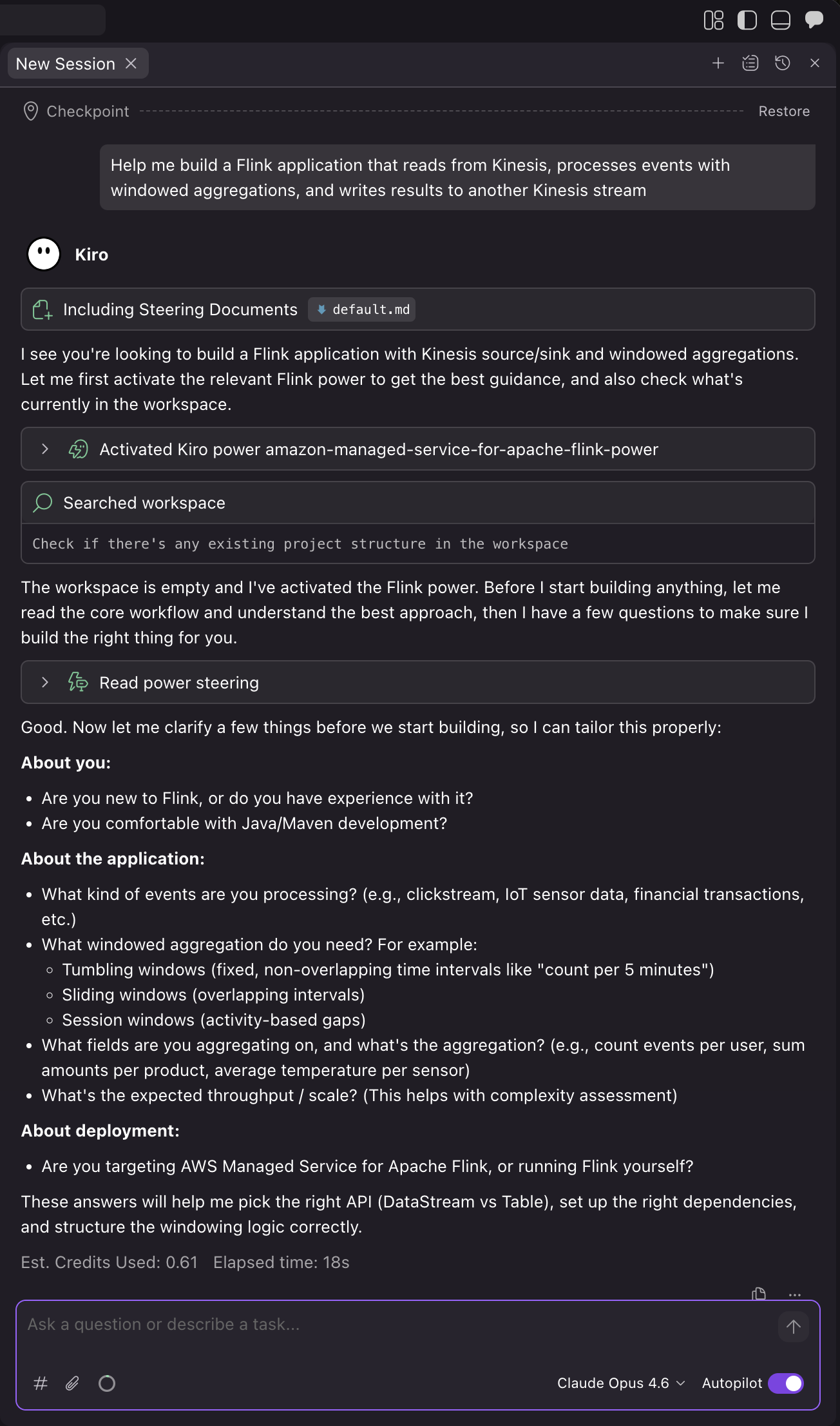
The AI assistant loads relevant guidance and walks you through the development process:

1. Confirm project requirements and details

Kiro automatically loads the Power based on the context of your prompt. The assistant then asks you questions about your use case to make sure that it builds the right application for your needs:

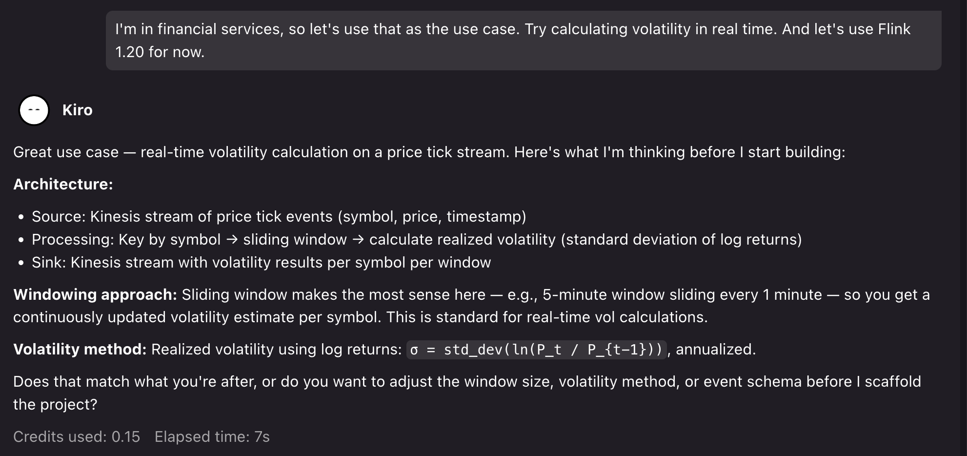
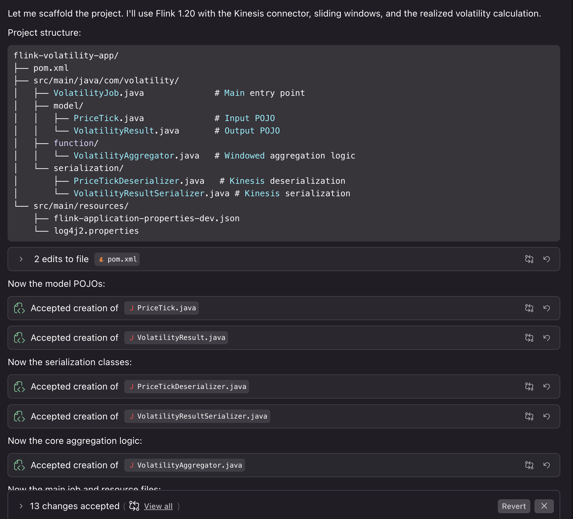
For the demo, we can prompt for a financial services use case: “I’m in financial services, so let’s use that as the use case. Try calculating volatility in real-time. And let’s use Flink 1.20 for now.”.

Kiro then confirms its assumptions and asks to proceed:

2. Project setup

After we confirm, Kiro generates a project with Flink 1.20 dependencies, Kinesis connectors, and proper scope configuration for Managed Service for Apache Flink deployment. The assistant creates the application structure with proper configuration separation between local development and Managed Service for Apache Flink service-level settings. Then, it creates a Kinesis source with proper deserialization and the sink with partitioning strategy, and windowed aggregation logic with proper state management, TTL configuration, and error handling.

Generated project structure with Flink dependencies and Kinesis connectors

Kiro also compiles the code to verify that it builds correctly. We can then proceed by asking Kiro to help us with running the application locally for testing.

3. Testing the project locally

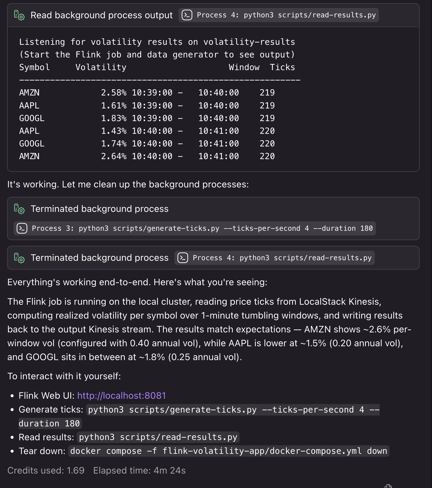
You can run the application locally to test the results. We can prompt: “Can we run this locally using something like LocalStack to test deploying the job and also see some example results?”

Kiro creates the necessary Docker resources, testing scripts, and deployment steps to run the application locally with synthetic resources. If it encounters bugs or detects issues during the local testing process, it fixes them so that your deployment runs smoothly:

Kiro creating Docker resources and local testing infrastructure

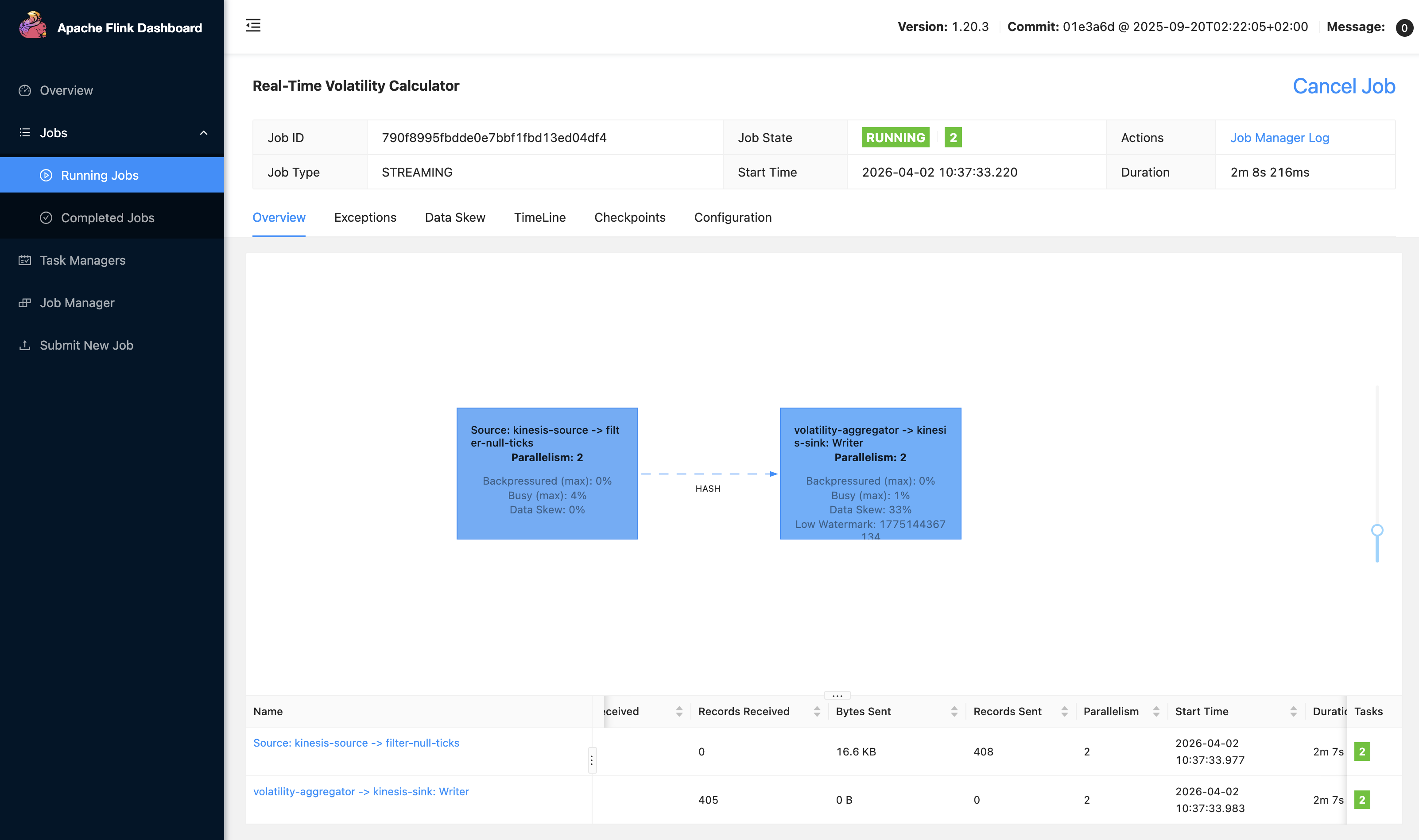
We can also access our local Flink UI to view our application:

Local Flink UI showing the running streaming application

4. Deploying the application to Managed Service for Apache Flink

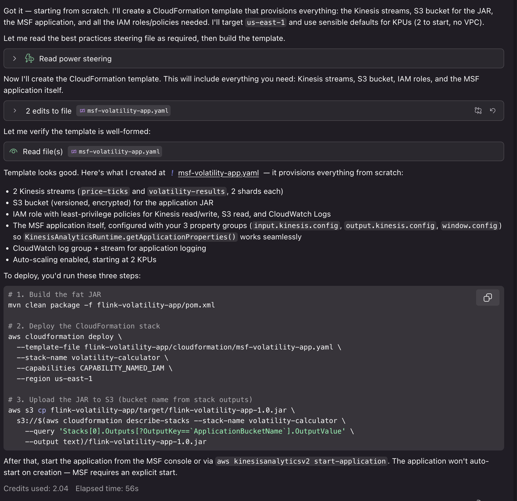
Now that our application is running and generating results end-to-end, we can use the Power for other tasks. For example, you can get guidance on KPU allocation and parallelism settings based on your expected throughput, configure monitoring with CloudWatch metrics, logging, and dashboards for operational visibility, or set up infrastructure as code (IaC) for deploying in Managed Service for Apache Flink. We can prompt: “This is great! Can you help me deploy this application to Managed Service for Apache Flink? I’d like to use CloudFormation for deployment.”

Kiro conversation summarizing creation of CloudFormation deployment resources

Using the generated AWS CloudFormation templates and deployment scripts, we can deploy our application to AWS with associated resources for Kinesis Data Streams, Amazon S3 buckets for application JAR files, CloudWatch log groups, and IAM roles. Deploying these resources requires IAM credentials with associated permissions and will incur cost for the associated resource usage.

In a traditional workflow, you build your application, deploy to Managed Service for Apache Flink, then discover performance issues or configuration problems in production. You spend time debugging checkpoint failures, serialization errors, or resource bottlenecks.With the Power/Skill, the AI assistant catches these issues during development. When you need complex aggregation and processing logic, it helps you to do so in a way that uses resources efficiently with Flink’s scaling model. When you create an application bug that would cause a crash in production, it helps you identify it early with local end-to-end testing. The Power is configured with guidance and best practices to help with the development process from start to finish.

Example: Migrating to Flink 2.2

The Managed Service for Apache Flink Kiro Power and Agent Skill provide contextual advice specific to your situation. For new developers, it walks through the complete workflow from project setup to deployment, explaining Managed Service for Apache Flink-specific concepts along the way. For migration projects, it analyzes your existing code for Flink 2.2 compatibility issues and provides targeted refactoring guidance. The following example shows how the tool helps with the complex task of migrating from Flink 1.x to 2.2.

1. Assessing migration compatibility

We can ask Kiro to help us upgrade our project from the previous example to Flink 2.2: “I need to migrate my Flink 1.x application to 2.2. Can you help me identify compatibility issues?”

The assistant loads the Managed Service for Apache Flink Kiro Power and analyzes our code to identify potential issues:

Kiro analyzing Flink 1.x code for 2.2 compatibility issues

In this case, using our generated project on Flink 1.20, Kiro identified the following compatibility issues for the upgrade:

  • Java 11 must move to Java 17 (minimum for Flink 2.2)
  • Flink version 1.20.3 must update to 2.2.0
  • The Kinesis connector must update from 5.1.0-1.20 to 6.0.0-2.0
  • Time references must change to java.time.Duration in window and lateness calls
  • The LocalStreamEnvironment instance of check must be removed (class removed in 2.2)
  • The isEndOfStream() override must be dropped from PriceTickDeserializer (method removed)
  • implements Serializable must be added to PriceTick and VolatilityResult

It also verified that some parts of the project are already Flink 2.2 compatible. The project uses the new Source Sink V2 APIs, the logging is 2.2 ready, the POJOs with no collection fields are state migration safe, and there are no Kryo registrations or TimeCharacteristic usage.

2. Implementing the migration

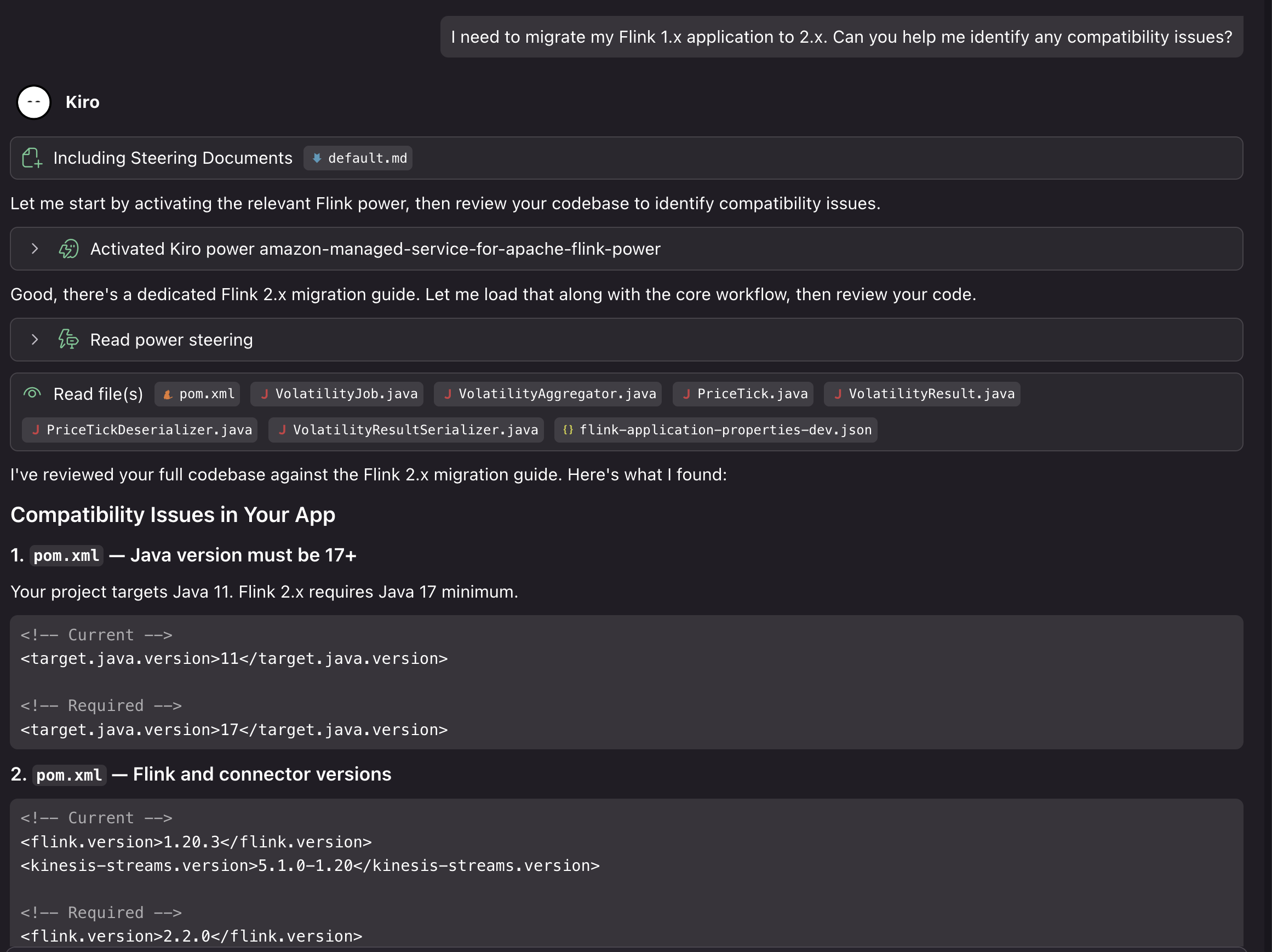
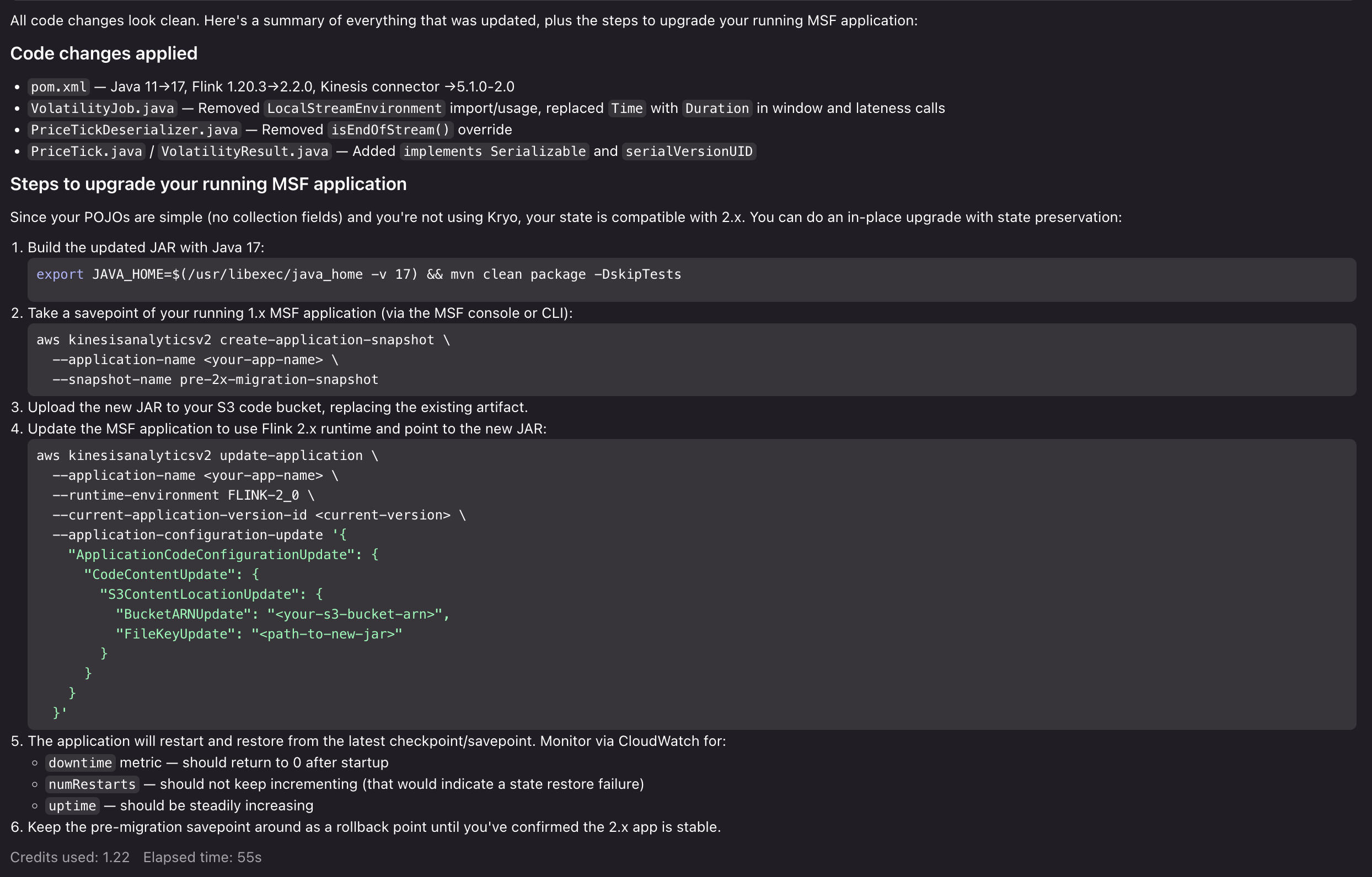
We can then ask Kiro to provide a step-by-step migration plan, both for updating the code and deploying to Managed Service for Apache Flink: “Can you help me update the application for Flink 2.2, and help me figure out the steps to upgrade my running Managed Service for Apache Flink application?”

Kiro evaluates the entire application code base. It evaluates it against the Power’s migration guidance and best practices, and provides a comprehensive analysis of the breaking changes, risks, and potential issues that would arise in the upgrade. After we approve the changes, Kiro then proceeds to make the necessary updates to make our application compatible with Flink 2.2 and provide us with a step-by-step upgrade process for the running application:

Kiro providing a step-by-step migration plan for Flink 2.2

Now that Kiro has prepared the application for Flink 2.2, highlighted migration risks, and provided us with a clear path to execute the upgrade, you can test the upgrade process with confidence. From here, we can proceed to run our Flink 2.2 application locally, test the upgrade process in a development environment in Managed Service for Apache Flink, and then execute the upgrade in our production environment. If we run into issues, we can return to the Kiro Power to get advice, resolve issues, and unblock our upgrade.

Cleanup

To remove the Power/Skill installation:

For Kiro:

  1. Open Kiro IDE.
  2. Navigate to the Powers tab.
  3. Uninstall the Amazon Managed Service for Apache Flink Power.

For Agent Skills:

# Remove per-project installation
rm -rf .cursor/skills/flink  # or .claude/skills/flink

# Remove personal installation
rm -rf ~/.cursor/skills/flink  # or ~/.claude/skills/flink
If you created Managed Service for Apache Flink applications or associated resources during development, clean the resources up:
  1. Delete the Managed Service for Apache Flink application from the AWS Console.
  2. Remove associated resources for sources and sinks, if created for development.
  3. Delete CloudWatch log groups if no longer needed.

Conclusion

In this post, we showed you how the Kiro Power and Agent Skill for Amazon Managed Service for Apache Flink brings AI-assisted development to stream processing. You can use the tool to overcome Flink’s learning curve, build applications following Managed Service for Apache Flink best practices, and migrate to Flink 2.2 with confidence. To get started, choose the path that fits your workflow:

  • If you use Kiro, install the Power from the Powers tab and start a new chat with a Flink-related prompt.
  • If you use Cursor, Claude Code, or another Agent Skills-compatible tool, clone the GitHub repository into your skills directory and reference the steering/ files for guidance.
  • If you are new to Amazon Managed Service for Apache Flink, review the Amazon Managed Service for Apache Flink Developer Guide and the Apache Flink documentation to build foundational knowledge alongside the Power/Skill.

We welcome your feedback. Report issues or request features through GitHub Issues, or contribute improvements via pull requests.


About the authors

Mazrim Mehrtens

Mazrim is a Sr. Specialist Solutions Architect for messaging and streaming workloads. Mazrim works with customers to build and support systems that process and analyze terabytes of streaming data in real time, run enterprise Machine Learning pipelines, and create systems to share data across teams seamlessly with varying data toolsets and software stacks.

Migrate to Apache Flink 2.2 on Amazon Managed Service for Apache Flink

Post Syndicated from Francisco Morillo original https://aws.amazon.com/blogs/big-data/migrate-to-apache-flink-2-2-on-amazon-managed-service-for-apache-flink/

Migrating to Apache Flink 2.2 on Amazon Managed Service for Apache Flink gives you access to Java 17 runtime, faster checkpoints and recovery through RocksDB 8.10.0, and SQL-native artificial intelligence and machine learning (AI/ML) inference. If you run Flink 1.x today, you might be dealing with an aging Java 11 runtime that will no longer receive standard support by the end of this year, slower state backend performance, and a fragmented API surface split across DataSet, DataStream, and legacy connector interfaces. Flink 2.2 addresses these gaps in a single major version upgrade.

Apache Flink is an open source distributed processing engine for stream and batch data, with first-class support for stateful processing and event-time semantics. Amazon Managed Service for Apache Flink removes the operational overhead of running Flink. You provide your application code, and the service provisions, scales, checkpoints, and patches the infrastructure for you.

In this post, we explain what’s new in Amazon Managed Service for Apache Flink 2.2, provide a guided migration using CLI commands, console instructions, and code examples, and show you how to monitor the upgrade and roll back if needed.

Before you upgrade: Flink 2.2 removes the DataSet API, drops Java 11 support, and replaces legacy connector interfaces. We recommend reviewing the Upgrading to Flink 2.2: Complete Guide and the State Compatibility Guide for Flink 2.2 Upgrades before upgrading production applications.

What’s new in Amazon Managed Service for Apache Flink 2.2

This release spans runtime upgrades, SQL, and Table API capabilities. The following sections break down each area.

Runtime and performance

These changes improve application performance and bring your runtime up to current standards.

  • Java 17 runtime Flink 2.2 requires Java 17. Build your application code with JDK 17 for better garbage collection, a more secure runtime, and modern language features like sealed classes and records. Java 11 is no longer supported.
  • Python 3.12 Flink 2.2 requires Python 3.9+, with Python 3.12 as the default. Python 3.8 is no longer supported.
  • RocksDB 8.10.0 – Your stateful applications benefit from improved I/O performance with the upgraded state backend, resulting in faster checkpoints and recovery.
  • Dedicated collection serializers – Improved serializers for Map, List, and Set types reduce serialization overhead, which lowers checkpoint sizes for applications that use these data structures frequently.
  • Kryo 5.6 – Kryo upgrades from version 2.24–5.6. This has state compatibility implications covered in the migration section.

SQL and Table API highlights

With Flink 2.2, you can:

For details on these features, see the Apache Flink 2.2 release documentation.

Migrating from Flink 1.x to 2.2

In-place version upgrades

You can upgrade a running Flink 1.x application to 2.2 using the UpdateApplication API, the AWS Management Console, AWS CloudFormation, the AWS SDK, and Terraform Modules. The upgrade preserves your application configuration, logs, metrics, tags, and, if your state and binaries are compatible.

Auto-rollback

With auto-rollback turned on, binary incompatibilities detected during job startup trigger an automatic revert to the previous Flink version within minutes, with no manual intervention required. For state incompatibilities that surface as restart loops after a successful upgrade, invoke the Rollback API to return to your previous version and state.

Unsupported open source features

The following Flink 2.2 features aren’t currently supported in Amazon Managed Service for Apache Flink because they’re still considered experimental: Materialized Tables, ForSt State Backend (disaggregated state storage), Java 21, and custom metric reporters/telemetry configurations. We continue to evaluate these features as they mature in the Apache Flink project and will share updates on availability. You can have a closer look to which features are supported in Apache Flink 2.2 features supported

Now that you know what’s changed, the next section walks through the migration process.

Prerequisites

Before starting the migration, confirm that you have the following in place:

  • An existing Apache Flink 1.x application running on Amazon Managed Service for Apache Flink.
  • JDK 17 installed in your local build environment.
  • The AWS Command Line Interface (AWS CLI) installed and configured with permissions to call the kinesisanalyticsv2 APIs (UpdateApplication, CreateApplicationSnapshot, DescribeApplication, RollbackApplication).
  • An Amazon Simple Storage Service (Amazon S3) bucket to upload your updated application JAR.

We recommend testing each phase on a non-production replica of your application before applying the same steps to production.

Step 1: Update your application code

Start by updating your Flink dependencies to version 2.2.0 and replacing deprecated APIs. The following sections show the most common changes.

Update your pom.xml:

<properties>
    <flink.version>2.2.0</flink.version>
    <java.version>17</java.version>
</properties>

Replace legacy Kinesis connectors:

Flink 2.2 removes the FlinkKinesisConsumer and FlinkKinesisProducer classes. The following example shows how to migrate to the FLIP-27 based KinesisStreamsSource.Before (Flink 1.x):

FlinkKinesisConsumer<String> consumer = new FlinkKinesisConsumer<>(
    "my-stream",
    new SimpleStringSchema(),
    consumerConfig);
env.addSource(consumer);

After (Flink 2.2):

KinesisStreamsSource<String> source = KinesisStreamsSource.<String>builder()
    .setStreamArn("arn:aws:kinesis:us-east-1:123456789012:stream/my-stream")
    .setDeserializationSchema(new SimpleStringSchema())
    .build();
env.fromSource(source, WatermarkStrategy.noWatermarks(), "Kinesis Source");

Update connector dependencies:

The following AWS connectors have Flink 2.x-compatible releases:

Connector Flink 2.x Artifact Version
Apache Kafka flink-connector-kafka 4.0.0-2.0
Amazon Kinesis Data Streams flink-connector-aws-kinesis-streams 6.0.0-2.0
Amazon Data Firehose flink-connector-aws-kinesis-firehose 6.0.0-2.0
Amazon DynamoDB flink-connector-dynamodb 6.0.0-2.0
Amazon Simple Queue Service (Amazon SQS) flink-connector-sqs 6.0.0-2.0

During writing, the JDBC, OpenSearch, and Prometheus connectors don’t yet have Flink 2.x-compatible releases. For the latest versions, see the Amazon Managed Service for Apache Flink connector documentation.

Beyond connector updates, make the following code changes:

  • Replace DataSet API usage with the DataStream API or Table API/SQL.
  • Replace Scala API usage with the Java API.
  • Verify that your build targets JDK 17.

Build your updated application JAR and upload it to Amazon S3 with a different file name than your current JAR (for example, my-app-flink-2.2.jar).

Step 2: Check state compatibility

Before upgrading, assess whether your application state is compatible with Flink 2.2. The Kryo upgrade from version 2.24 to 5.6 changes the binary format of serialized state. Applications using POJOs with Java collections (HashMap, ArrayList, HashSet) are the most common source of incompatibility.

Quick compatibility check:

Serialization type Compatible?
Avro (SpecificRecord, GenericRecord) ✅ Yes
Protobuf ✅ Yes
POJOs without collections ✅ Yes
Custom TypeSerializers (no Kryo delegation) ✅ Yes
POJOs with Java collections ❌ No
Scala case classes ❌ No
Types using Kryo fallback ❌ No

Check your logs for Kryo fallback:

Search your application logs for this pattern, which indicates a type is falling back to Kryo serialization:Class class <className> cannot be used as a POJO type

Step 3: Turn on auto-rollback and automatic snapshots

Turn on auto-rollback so the service automatically reverts to the previous version if the upgrade fails. Also, verify that automatic snapshots are turned on. The service takes a snapshot before the upgrade that serves as your rollback point.

Check current settings:

aws kinesisanalyticsv2 describe-application \
    --application-name MyApplication \
    --query 'ApplicationDetail.ApplicationConfigurationDescription.{
        AutoRollback: ApplicationSystemRollbackConfigurationDescription.RollbackEnabled,
        AutoSnapshots: ApplicationSnapshotConfigurationDescription.SnapshotsEnabled
    }'

Turn on both if they’re not already active:

aws kinesisanalyticsv2 update-application \
    --application-name MyApplication \
    --current-application-version-id <version-id> \
    --application-configuration-update '{
        "ApplicationSystemRollbackConfigurationUpdate": {
            "RollbackEnabledUpdate": true
        },
        "ApplicationSnapshotConfigurationUpdate": {
            "SnapshotsEnabledUpdate": true
        }
    }'

Step 4: Take a manual snapshot (recommended)

Although the upgrade process takes an automatic snapshot, taking a manual snapshot gives you a named restore point that you can quickly identify.

aws kinesisanalyticsv2 create-application-snapshot \
    --application-name MyApplication \
    --snapshot-name pre-flink-2.2-upgrade

Verify that the snapshot is ready before proceeding:

aws kinesisanalyticsv2 describe-application-snapshot \
    --application-name MyApplication \
    --snapshot-name pre-flink-2.2-upgrade

Wait until SnapshotStatus is READY.

Step 5: Run the upgrade

Run the upgrade while the application is in RUNNING or READY (stopped) state. The following example upgrades a running application and points to the new JAR.

AWS CLI:

aws kinesisanalyticsv2 update-application \
    --application-name MyApplication \
    --current-application-version-id <version-id> \
    --runtime-environment-update FLINK-2_2 \
    --application-configuration-update '{
        "ApplicationCodeConfigurationUpdate": {
            "CodeContentUpdate": {
                "S3ContentLocationUpdate": {
                    "FileKeyUpdate": "my-app-flink-2.2.jar"
                }
            }
        }
    }'

AWS Management Console:

To upgrade from the console, follow these steps:

  1. Navigate to your application in the Amazon Managed Service for Apache Flink console.
  2. Choose Configure.
  3. Select the Flink 2.2 runtime.
  4. Point to your new application JAR on Amazon S3.
  5. Select the snapshot to restore from (use Latest to start from the most recent snapshot).
  6. Choose Update.

AWS CloudFormation:

Update the RuntimeEnvironment field in your template. AWS CloudFormation now performs an in-place update instead of deleting and recreating the application.

Terraform:

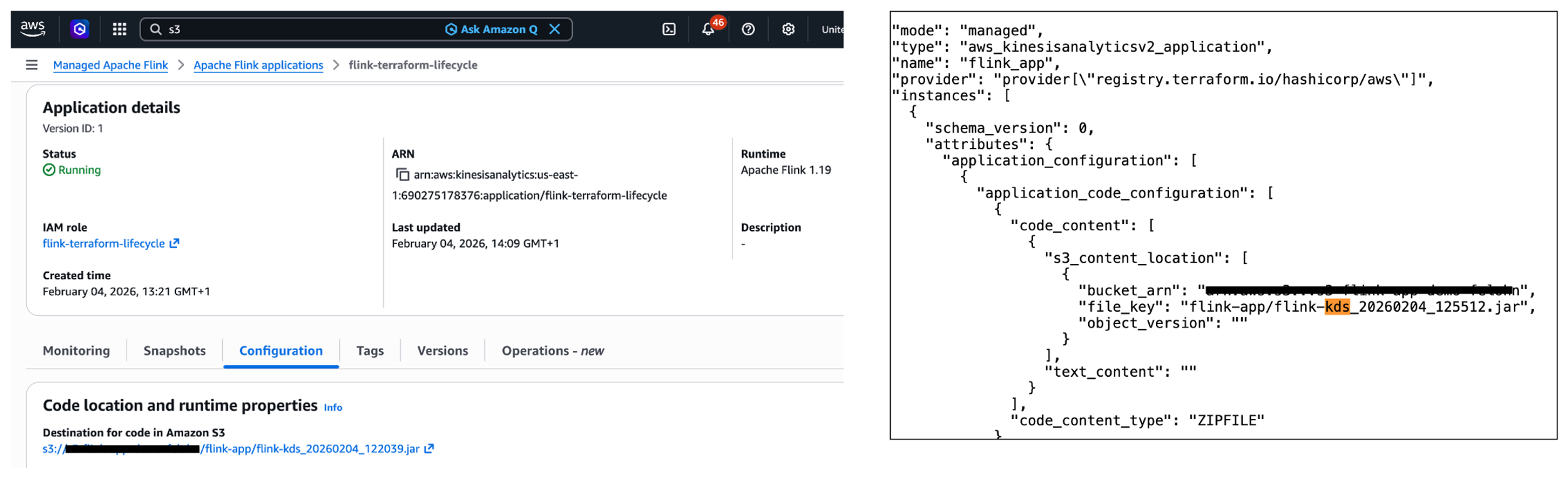
If you manage your Flink application with Terraform, you can perform the same in-place upgrade by updating the runtime_environment and code reference in your aws_kinesisanalyticsv2_application resource. Note: Terraform support for FLINK-2_2 requires AWS provider version 6.40.0 or later (released April 8, 2026). Earlier provider versions don’t recognize this runtime value. First, update your provider version constraint:

terraform {
  required_providers {
    aws = {
      source  = "hashicorp/aws"
      version = ">= 6.40.0"
    }
  }
}

Then run terraform init -upgrade to pull the new provider.Next, update your application resource. Change runtime_environment from “FLINK-1_20” to “FLINK-2_2” and point to your new JAR:

resource "aws_kinesisanalyticsv2_application" "my_app" {
  name                   = "MyApplication"
  runtime_environment    = "FLINK-2_2"
  service_execution_role = aws_iam_role.flink.arn
  application_configuration {
    application_code_configuration {
      code_content_type = "ZIPFILE"
      code_content {
        s3_content_location {
          bucket_arn = aws_s3_bucket.app_code.arn
          file_key   = "my-app-flink-2.2.jar"
        }
      }
    }
    application_snapshot_configuration {
      snapshots_enabled = true
    }
    flink_application_configuration {
      checkpoint_configuration {
        configuration_type = "DEFAULT"
      }
      monitoring_configuration {
        configuration_type = "CUSTOM"
        log_level          = "INFO"
        metrics_level      = "APPLICATION"
      }
      parallelism_configuration {
        auto_scaling_enabled = true
        configuration_type   = "CUSTOM"
        parallelism          = 4
        parallelism_per_kpu  = 1
      }
    }
  }
}

Run the upgrade:

terraform plan    # Review the in-place update
terraform apply   # Apply the runtime change

Terraform will perform an in-place update of the application, changing the runtime version and code location. The application will restart with the new Flink 2.2 runtime. To roll back with Terraform, revert runtime_environment to “FLINK-1_20”, point file_key back to your original JAR, and run terraform apply again. Note that you cannot restore a Flink 2.2 snapshot on Flink 1.x, so the rollback will start from the last Flink 1.x snapshot.

Important Terraform considerations:

  • Auto-rollback and the RollbackApplication API aren’t directly exposed as Terraform resource attributes. If you need auto-rollback during the upgrade, enable it using the AWS CLI (Step 3) before running terraform apply, or use a provisioner/null_resource to call the CLI.
  • Always take a manual snapshot (Step 4) before running terraform apply for the upgrade. Terraform doesn’t automatically snapshot before updating the runtime.

Step 6: Monitor the upgrade

After initiating the upgrade, monitor the application to verify that it completes successfully.

Check application status:

The application should transition through RUNNING → UPDATING → RUNNING. Confirm the runtime version changed to 2.2:

aws kinesisanalyticsv2 describe-application \
    --application-name MyApplication \
    --query 'ApplicationDetail.RuntimeEnvironment'

What to watch for:

Scenario What happens Action
Binary incompatibility Upgrade operation fails. Auto-rollback reverts to the previous version automatically. Check operation logs for the exception, fix your code, and retry.
State incompatibility Upgrade appears to succeed but the application enters restart loops. Monitor numRestarts metric. If restarts are continuous, invoke the Rollback API manually. Review the [State Compatibility Guide].
Successful upgrade numRestarts is zero, uptime is increasing, checkpoints are completing. Proceed to validation.

Key CloudWatch metrics to monitor:

  1. numRestarts: should be zero after upgrade
  2. lastCheckpointDuration: should be similar to pre-upgrade values
  3. numberOfFailedCheckpoints: should remain at zero
  4. uptime: should be steadily increasing

Step 7: Validate application behavior

After the application is running on Flink 2.2:

  • Confirm that data is being read from sources and written to sinks.
  • Compare the output with your pre-upgrade baseline.
  • Monitor latency, throughput, checkpoint duration, and resource utilization.
  • Run for at least 24 hours to confirm stable behavior: no memory leaks, no unexpected restarts, consistent checkpoint sizes.

Step 8: Rollback (if needed)

If the application is running but is unhealthy after the upgrade, invoke the Rollback API:

AWS CLI:

aws kinesisanalyticsv2 rollback-application \
    --application-name MyApplication \
    --current-application-version-id <version-id>

AWS Management Console:

  • Navigate to your application.
  • Choose Actions, Roll back.
  • Confirm the rollback.

During rollback, the application stops, reverts to the previous Flink version and application code, and restarts from the snapshot taken before the upgrade.

Important: You can’t restore a Flink 2.2 snapshot on Flink 1.x. Rollback uses the snapshot taken before the upgrade. This is why Steps 3 and 4 are critical.

Next steps

Your path depends on where you are today:

  1. If you’re new to Apache Flink: Start with the guide to choosing the right API and language, the Amazon Managed Service for Apache Flink getting started guide, and the Amazon Managed Service for Apache Flink workshop.
  2. If you’re running Flink 1.x in production: Follow the migration steps in this post on a non-production replica first, then apply to production. For the complete reference, see the Upgrading to Flink 2.2: Complete Guide and the State Compatibility Guide for Flink 2.2 Upgrades.
  3. If you’re evaluating Flink 2.2 features: Launch a new application on the Flink 2.2 runtime to explore SQL/ML capabilities, the VARIANT data type, and the new join operators. See the Amazon Managed Service for Apache Flink sample applications on GitHub for reference architectures.
  4. If you need help with your migration: Use the Kiro Power and Agent Skill for Amazon Managed Service for Apache Flink to identify compatibility issues in your existing codebase and receive guidance on refactoring steps. You can also open a case through AWS Support, post a question on AWS re:Post for Amazon Managed Service for Apache Flink, or reach out through the Apache Flink community.

For the Apache Flink 2.2 documentation, see nightlies.apache.org/flink/flink-docs-release-2.2. For Amazon Managed Service for Apache Flink documentation, see the Developer Guide. For pricing, see the pricing page.

Conclusion

With Apache Flink 2.2 on Amazon Managed Service for Apache Flink, you get a modern Java 17 runtime, SQL-native AI/ML inference, improved state management performance, and a streamlined API surface. In-place upgrades with state preservation and auto-rollback make the migration straightforward. Test on a replica, follow the steps in this post, and start building on Flink 2.2.


About the authors

Francisco Morillo

Francisco Morillo is a Sr. Streaming Specialist Solutions Architect at AWS, helping customers design and operate real-time data processing applications using Amazon Managed Service for Apache Flink and Amazon Managed Streaming for Apache Kafka.

Mayank Juneja

Mayank Juneja is a Senior Product Manager at AWS, leading Amazon Managed Service for Apache Flink. He lives at the intersection of real-time data streaming and AI, previously driving Flink SQL and AI inference products at Confluent.

Building unified data pipelines with Apache Iceberg and Apache Flink

Post Syndicated from Nikhil Jha original https://aws.amazon.com/blogs/big-data/building-unified-data-pipelines-with-apache-iceberg-and-apache-flink/

You can process real-time data from your data lake with Amazon Managed Service for Apache Flink without maintaining two separate pipelines. Yet many teams do exactly that, and the cost adds up fast. In this post, you build a unified pipeline using Apache Iceberg and Amazon Managed Service for Apache Flink that replaces the dual-pipeline approach. This walkthrough is for intermediate AWS users who are comfortable with Amazon Simple Storage Service (Amazon S3) and AWS Glue Data Catalog but new to streaming from Apache Iceberg tables.

The dual-pipeline problem

Traditional dual-pipeline architecture with separate batch and streaming paths, each with its own ingestion, processing, storage, and serving layers, processing the same source data independently.

This dual-pipeline approach creates three problems:

  • Double the infrastructure costs. You run and pay for two separate compute environments, two storage layers, and two sets of monitoring. For example, if you’re spending $10,000/month on separate streaming and batch infrastructure, a meaningful portion of that spend is pure duplication.
  • Data synchronization issues. Your batch and streaming consumers read from different copies of the data, processed at different times. When a transaction shows up in your real-time dashboard but not in your batch report (or vice versa), debugging the inconsistency takes hours.
  • Operational complexity. Two pipelines mean two deployment processes, two failure modes to monitor, and two sets of schema evolution to manage. Your team spends time reconciling systems instead of building features.

Where this pattern fits

Before diving into the implementation, consider whether streaming from your data lake is the right approach for your use case.

Streaming from Apache Iceberg tables works well when you need data available within seconds to minutes and you query recent data frequently, multiple times per hour. Common scenarios include:

  • Operational data stores — Stream customer profile updates to serve downstream applications like recommendation engines. When a customer updates their preferences, those changes reach your operational data store within seconds.
  • Fraud detection — Stream transactions for immediate analysis. Start with a 3-second monitor interval and adjust based on your detection accuracy needs.
  • Live dashboards — Power real-time analytics directly from your lake. This is the strongest starting point if you’re evaluating the approach for the first time, because the feedback loop is immediate and straightforward to validate.
  • Event-driven architectures — Trigger downstream processes based on data changes in your Apache Iceberg tables.

Batch processing remains more cost-effective when you process data once per day or less, or you primarily query historical data. Batch queries on Apache Iceberg tables cost less because they don’t require a continuous Apache Flink runtime.

How Apache Iceberg solves this

Apache Iceberg’s snapshot-based architecture removes the need for a separate streaming pipeline. Think of snapshots like Git commits for your data. Each time you write data to your Iceberg table, Iceberg creates a new snapshot that points to the new data files while preserving references to existing files. Apache Flink reads only the changes between snapshots (the new files that arrived after the last checkpoint), rather than scanning the entire table. Atomicity, Consistency, Isolation, Durability (ACID) transactions prevent your concurrent reads and writes from producing partial or inconsistent results. For example, if your batch extract, transform, and load (ETL) job is writing 10,000 records while your Flink application is reading, ACID transactions mean that your streaming query sees either the complete batch of 10,000 records or none of them, not a partial set that could skew your analytics.

The result is a single pipeline that handles both real-time and batch access from the same data, through the same storage layer, with the same schema.

Solution architecture

Your architecture uses four AWS services and one open source table format working together. The following diagram shows how these components connect, replacing the dual-pipeline pattern shown earlier with a single unified flow.

Unified pipeline architecture with data flowing from Amazon S3 through Apache Iceberg tables, with AWS Glue Data Catalog managing metadata, and Amazon Managed Service for Apache Flink consuming incremental snapshots for near real-time processing.

Your source data lands in Amazon S3 as Apache Iceberg table files. AWS Glue Data Catalog tracks the metadata and schema. When new data arrives, Apache Iceberg creates a new snapshot that your application detects. Your Flink application monitors these snapshots and processes new records incrementally, reading only the files that arrived after the last checkpoint, not the entire table.

You use four main components:

  • Amazon S3 — Foundational storage layer for your data lake
  • Data Catalog — Metadata and schema management for Apache Iceberg tables
  • Apache Iceberg — Table format with snapshot-based streaming capabilities
  • Amazon Managed Service for Apache Flink — Stream processing and incremental consumption

Important notices

Before implementing this solution, evaluate these risks for your environment:

  • Data security: Streaming from data lakes exposes data to additional processing systems. Classify your data before implementation—customer profile updates and transaction data typically contain personally identifiable information (PII) and treat them as confidential. Apply encryption at rest and in transit for confidential data. Key risks include unauthorized data access through misconfigured Amazon S3 bucket policies or overly permissive IAM roles. Mitigations: use the resource-scoped IAM policy and TLS-enforcing bucket policy provided in the Security section.
  • Data integrity: Misconfigured checkpoints or schema changes during streaming can lead to data inconsistency. Mitigations: enable exactly-once processing semantics and test schema evolution in a non-production environment first.
  • Compliance: Verify that real-time data processing meets your regulatory requirements. For workloads subject to HIPAA, confirm that you use HIPAA Eligible Services and have a Business Associate Agreement (BAA) with AWS. For PCI-DSS or GDPR workloads, review the relevant compliance documentation on the AWS Compliance page. Implement data retention policies that comply with your regulatory framework.
  • Cost: Nearly continuous streaming incurs ongoing compute costs. Monitor usage to avoid unexpected charges. Cost estimates in this post are based on pricing as of March 2026 and might change. Verify current pricing on the relevant AWS service pricing pages.
  • Operational: Pipeline failures might impact downstream systems. Implement monitoring and alerting before running in production.

Prerequisites

Before you begin, make sure that you have the following in place. This walkthrough assumes intermediate Python skills (comfortable with functions, error handling, and environment variables), basic Apache Flink concepts (streaming compared to batch processing), and basic AWS Identity and Access Management (AWS IAM) knowledge (creating roles and attaching policies). Plan for approximately 90–120 minutes, including setup, implementation, and testing. First-time setup might take longer as you download dependencies and configure AWS resources. Expected AWS costs: approximately $5–10 if you complete the walkthrough within 2 hours and clean up resources immediately afterward. The primary cost driver is Amazon Managed Service for Apache Flink runtime ($0.11/hour per Kinesis Processing Unit (KPU)). You can minimize costs by stopping your application when not in use.

  • An AWS account with AWS IAM permissions for: s3:GetObject, s3:PutObject, s3:ListBucket on your data bucket; glue:GetDatabase, glue:GetTable for catalog access; and flink:CreateApplication, flink:StartApplication for Amazon Managed Service for Apache Flink
  • An existing Amazon S3 bucket for your data lake
  • An AWS Glue Data Catalog database configured
  • Apache Flink 1.19.1 installed locally
  • Python 3.8 or later
  • Java 11 or a more recent version
  • AWS Command Line Interface (AWS CLI) configured with credentials (aws configure)

Required Java Archive (JAR) dependencies

You need multiple JAR files because your Flink application coordinates between different systems—Amazon S3 for storage, AWS Glue for metadata, Hadoop for file operations, and Apache Iceberg for the table format. Each JAR handles a specific part of this integration. Missing even one causes ClassNotFoundException errors at runtime.

  • iceberg-flink-runtime-1.19-1.6.1.jar — Core Apache Iceberg integration with Apache Flink
  • iceberg-aws-bundle-1.6.1.jar — AWS-specific Apache Iceberg functionality for Amazon S3 and AWS Glue
  • flink-s3-fs-hadoop-1.19.1.jar — Provides Apache Flink read and write access to Amazon S3
  • flink-sql-connector-hive-3.1.3_2.12-1.19.1.jar — Hive metastore connector for catalog compatibility
  • hadoop-common-3.4.0.jar — Core Hadoop libraries required by Apache Iceberg
  • flink-shaded-hadoop-2-uber-2.8.3-10.0.jar — Repackaged Hadoop dependencies that avoid version conflicts with Apache Flink
  • hadoop-hdfs-client-3.4.0.jar — Hadoop Distributed File System (HDFS) client libraries for file system operations
  • flink-json-1.19.1.jar — JSON format support for Apache Flink
  • hadoop-aws-3.4.0.jar — Hadoop integration with AWS services
  • hadoop-client-3.4.0.jar — Hadoop client libraries
  • aws-java-sdk-bundle-1.12.261.jar — AWS SDK for authentication and service access
jars = [
    "flink-s3-fs-hadoop-1.19.1.jar",
    "flink-sql-connector-hive-3.1.3_2.12-1.19.1.jar",
    "hadoop-common-3.4.0.jar",
    "flink-shaded-hadoop-2-uber-2.8.3-10.0.jar",
    "iceberg-flink-runtime-1.19-1.6.1.jar",
    "iceberg-aws-bundle-1.6.1.jar",
    "hadoop-hdfs-client-3.4.0.jar",
    "flink-json-1.19.1.jar",
    "hadoop-aws-3.4.0.jar",
    "hadoop-client-3.4.0.jar",
    "aws-java-sdk-bundle-1.12.261.jar"
]

Technical implementation

The sample code in this post is available under the MIT-0 license.This section walks you through building the streaming pipeline step by step. You create a single Python file, iceberg_streaming.py, with three functions that run in sequence. Your main() function calls them in order: set up the Apache Flink environment, register the Data Catalog, then start the streaming query.

Set up your Apache Flink environment

To prepare your Apache Flink environment:

  1. Download the required JAR files listed in the prerequisites section.
  2. Place the JAR files in a lib directory in your project folder.
  3. Configure your HADOOP_CLASSPATH environment variable to point to the lib directory.
  4. Create your streaming execution environment by adding the following function to iceberg_streaming.py:
def setup_environment():
    """Configure the Flink streaming runtime."""
    try:
        os.environ['HADOOP_CLASSPATH'] = os.path.join(os.getcwd(), 'lib', '*')
        env = StreamExecutionEnvironment.get_execution_environment()
        env.set_parallelism(1)
        settings = EnvironmentSettings.new_instance().in_streaming_mode().build()
        t_env = StreamTableEnvironment.create(env, settings)
        return t_env
    except Exception as e:
        print(f"Failed to initialize Flink environment: {e}")
        raise
  1. Verify your environment by running flink –version. If the command isn’t found, confirm that Apache Flink 1.19.1 is installed and that your PATH includes the Flink bin directory.

Configure AWS Glue Data Catalog

To connect your Flink application to Data Catalog:

  1. Open your iceberg_streaming.py file.
  2. Add the create_iceberg_source() function shown in the following section.
  3. Replace the placeholder values with your actual AWS resources before running. These values are static configuration strings, not user input — do not construct them from external or untrusted sources at runtime.
  4. Save the file.
def create_iceberg_source(t_env):
    """Register the AWS Glue Data Catalog as an Iceberg catalog."""
    try:
        catalog_sql = """
        CREATE CATALOG glue_catalog WITH (
            'type'='iceberg',
            'catalog-impl'='org.apache.iceberg.aws.glue.GlueCatalog',
            'warehouse'='s3://<example-data-lake-bucket>',
            'io-impl'='org.apache.iceberg.aws.s3.S3FileIO',
            'aws.region'='us-east-1',
            'hadoop-conf.fs.s3a.aws.credentials.provider'=
                'com.amazonaws.auth.DefaultAWSCredentialsProviderChain',
            'hadoop-conf.fs.s3a.endpoint'='s3.amazonaws.com',
            'property-version'='1'
        )
        """
        t_env.execute_sql(catalog_sql)
        t_env.use_catalog("glue_catalog")
        t_env.use_database("streaming_db")
    except Exception as e:
        print(f"Failed to configure Iceberg catalog: {e}")
        raise

Set up streaming logic

This function configures Apache Flink to monitor your Apache Iceberg table continuously and process new records as they arrive. Checkpointing runs every 10 seconds to track progress—if the job restarts, it resumes from the last checkpoint rather than reprocessing the entire table.Notice the monitor-interval parameter, it controls how frequently Apache Flink checks for new Apache Iceberg snapshots. A 3-second interval provides near real-time processing but generates approximately 1,200 Amazon S3 LIST API calls per hour (at $0.005 per 1,000 requests, roughly $0.04/month per table based on pricing as of March 2026). For less time-sensitive workloads, increase this to 30s to reduce API costs by 90%.Replace customer_events with the name of your Apache Iceberg table in Data Catalog:

def process_record(row):
    """Validate and process each record from the stream."""
    try:
        if row is None:
            raise ValueError("Received null row")
        required_fields = ["event_type", "timestamp"]
        for field in required_fields:
            if field not in row:
                raise ValueError(f"Missing required field: {field}")
        # Validate field types and content
        if not isinstance(row.get("event_type"), str) or len(row["event_type"]) > 256:
            raise ValueError("event_type must be a string under 256 characters")
        if not isinstance(row.get("timestamp"), (str, int)):
            raise ValueError("timestamp must be a string or integer")
        # Replace with your business logic
        print(f"Processing record: {row}")
    except ValueError as e:
        print(f"Validation error for record {row}: {e}")
    except Exception as e:
        print(f"Error processing record {row}: {e}")
def stream_data(t_env):
    """Start the streaming query and process results."""
    try:
        configuration = t_env.get_config().get_configuration()
        configuration.set_string("table.dynamic-table-options.enabled", "true")
        configuration.set_string("execution.checkpointing.interval", "10000")
        query = """
        SELECT * FROM customer_events /*+ OPTIONS(
            'streaming'='true',
            'monitor-interval'='3s',
            'table.exec.iceberg.cell-based-snapshot'='true'
        ) */
        """
        table_result = t_env.execute_sql(query)
        with table_result.collect() as results:
            for row in results:
                process_record(row)
    except Exception as e:
        print(f"Streaming query failed: {e}")
        raise

Putting it together

Your main() function calls the three steps in order:

def main():
    try:
        t_env = setup_environment()
        create_iceberg_source(t_env)
        stream_data(t_env)
    except Exception as e:
        print(f"Pipeline failed: {e}")
        raise
if __name__ == "__main__":
    main()

Run the pipeline locally:python iceberg_streaming.pyPackage the application and submit it to Amazon Managed Service for Apache Flink using the console or the AWS Command Line Interface (AWS CLI).

Running in production

Moving from a local test to a production deployment requires tuning four areas: performance, monitoring, cost, and security. This section covers the key decisions for each.

Performance tuning

Determine your latency requirements before tuning. For fraud detection, you need subsecond processing. For daily reporting dashboards, you can tolerate minutes of delay.

Partition pruning reduces the amount of data scanned per query. Proper partitioning can significantly reduce query times for time series data partitioned by date. To implement, create your Apache Iceberg table with partition columns (PARTITIONED BY (date_column) in your CREATE TABLE statement), then include partition filters in your WHERE clause: WHERE date_column >= CURRENT_DATE - INTERVAL '7' DAY.

Parallel processing matches your data volume and throughput requirements. For most workloads under 10,000 records per second, a parallelism of 1–4 is sufficient. Scale up incrementally and monitor backpressure metrics (indicators that data arrives faster than your pipeline processes it, causing queuing) to find the right setting.

Checkpoint tuning balances reliability and latency. Consider how much data you can afford to reprocess after a failure. If you process 1,000 records per second with 10-second checkpoints, a failure means reprocessing up to 10,000 records. When that’s acceptable, 10 seconds works well. For faster recovery or higher volumes, reduce to 5 seconds.

Resource allocation — Right-size your Apache Flink cluster to avoid over-provisioning. Monitor CPU and memory utilization during your initial runs and adjust task manager resources accordingly.

Monitoring

Configure your production deployment with the following checkpoint settings. These work well for moderate data volumes (up to 10,000 records per second), providing exactly-once processing semantics. This means that the pipeline processes each record exactly once, even if your application restarts. Adjust the checkpoint interval based on your latency requirements. Add this to your setup_environment() function after creating the table environment.

config_dict = {
    "execution.checkpointing.interval": "30000",
    "execution.checkpointing.mode": "EXACTLY_ONCE",
    "execution.checkpointing.timeout": "600000",
    "state.backend": "filesystem",
    "state.checkpoints.dir": "s3://<example-data-lake-bucket>/checkpoints"
}

Use Amazon CloudWatch to track checkpoint duration, records processed per second, and backpressure metrics. A 10-second checkpoint interval means writing state to Amazon S3 360 times per hour. For a 1 MB state size, that’s approximately 8.6 GB per day in checkpoint storage—at Amazon S3 Standard pricing of $0.023/GB, roughly $0.20/day or $6/month per application based on current pricing. If the checkpoint duration exceeds 50% of your interval, increase the interval or add parallelism.

Cost management

Use Amazon S3 Intelligent-Tiering for your Apache Iceberg data files, which typically have predictable access patterns after initial processing. Configure Apache Iceberg’s table expiration to automatically clean up early snapshots. This can reduce storage costs by an estimated 20–30%, though your results vary depending on write frequency and retention policies.

Right-size your Apache Flink resources based on actual throughput needs. Start with a minimal configuration and scale up based on observed backpressure and checkpoint duration metrics. Use Amazon Elastic Compute Cloud (Amazon EC2) Spot Instances where workload interruptions are acceptable, for example, in development and testing environments.

Set data retention policies on both your Apache Iceberg tables and checkpoint storage to avoid storing data longer than necessary.

Security

Security is a shared responsibility between you and AWS. AWS is responsible for the security of the cloud, including the hardware, software, networking, and facilities that run AWS services. You are responsible for security in the cloud, configuring access controls, encrypting data, and managing your application security. Apply these controls in priority order.

AWS IAM roles — Use AWS IAM roles with least-privilege access, scoped to specific resources. The following example policy restricts permissions to your data lake bucket and AWS Glue catalog:

{
  "Version": "2012-10-17",
  "Statement": [
    {
      "Effect": "Allow",
      "Action": ["s3:GetObject", "s3:PutObject"],
      "Resource": "arn:aws:s3:::<example-data-lake-bucket>/*"
    },
    {
      "Effect": "Allow",
      "Action": "s3:ListBucket",
      "Resource": "arn:aws:s3:::<example-data-lake-bucket>",
      "Condition": {
        "StringEquals": {
          "aws:SourceVpce": "<your-vpc-endpoint-id>"
        }
      }
    },
    {
      "Effect": "Allow",
      "Action": ["glue:GetDatabase", "glue:GetTable"],
      "Resource": [
        "arn:aws:glue:us-east-1:<account-id>:catalog",
        "arn:aws:glue:us-east-1:<account-id>:database/streaming_db",
        "arn:aws:glue:us-east-1:<account-id>:table/streaming_db/*"
      ]
    },
    {
      "Effect": "Allow",
      "Action": ["kms:Decrypt", "kms:GenerateDataKey"],
      "Resource": "arn:aws:kms:us-east-1:<account-id>:key/<your-kms-key-id>"
    }
  ]
}

Scoping permissions to specific Amazon S3 buckets, AWS Glue databases, and AWS Key Management Service (AWS KMS) keys restrict access to only the resources your pipeline requires. Review IAM policies quarterly using the IAM Access Analyzer to identify and remove unused permissions.

Encryption — Configure server-side encryption with AWS Key Management Service (AWS KMS) customer managed keys (SSE-KMS) for your Amazon S3 buckets. Using customer managed keys requires additional review from your security team. Confirm your key management policies, rotation procedures, and access controls before implementation. Enable automatic key rotation annually. For encryption in transit, enforce TLS by adding a bucket policy that denies non-HTTPS access:

{
  "Effect": "Deny",
  "Principal": "*",
  "Action": ["s3:GetObject", "s3:PutObject", "s3:ListBucket"],
  "Resource": [
    "arn:aws:s3:::<example-data-lake-bucket>/*",
    "arn:aws:s3:::<example-data-lake-bucket>"
  ],
  "Condition": {
    "Bool": { "aws:SecureTransport": "false" }
  }
}

Amazon S3 bucket hardening — Enable Block Public Access on your buckets to prevent accidental public exposure:

aws s3api put-public-access-block \
  --bucket <example-data-lake-bucket> \
  --public-access-block-configuration \
  BlockPublicAcls=true,IgnorePublicAcls=true,BlockPublicPolicy=true,RestrictPublicBuckets=true

Enable versioning on buckets that store critical data and checkpoints to protect against accidental deletion. For production environments with sensitive data, consider enabling MFA Delete on versioned buckets. Enable S3 server access logging to track requests for security auditing.

Amazon Virtual Private Cloud (Amazon VPC) –Use Amazon VPC endpoints for private communication between your Apache Flink cluster and AWS services, removing public internet routing by keeping traffic within the AWS network.

Access logging – Enable AWS CloudTrail data events to log Amazon S3 object-level API calls (GetObject, PutObject) and Data Catalog API calls. Store logs in a separate Amazon S3 bucket with restricted access and enable log file integrity validation. Run regular compliance checks using AWS Config.

Operational practices

Set up a continuous integration and continuous deployment (CI/CD) pipeline to automate deployment and testing. Use version control to track schema and code changes. With Apache Iceberg’s schema evolution support, you can add columns without rewriting existing data files. Establish rollback procedures using Apache Iceberg’s snapshot-based architecture, so you can roll back to a previous table state if a bad write corrupts your data.

Troubleshooting

If you run into issues during setup or execution, use the following table to diagnose common errors.

Error Cause Solution
ClassNotFoundException Missing JAR files Check the dependencies in your lib directory and confirm HADOOP_CLASSPATH points to the correct path
Table not found Database name mismatch Check that the database name in t_env.use_database() matches the AWS Glue database where you registered your table
Checkpoint failures Amazon S3 permissions Check that your Amazon S3 bucket policy grants s3:PutObject for the checkpoint location
AWS credential errors Missing AWS IAM configuration Check that the AWS IAM role attached to your Apache Flink application has glue:GetTable, glue:GetDatabase, and s3:GetObject permissions on the relevant resources
Snapshot not found Table modified during query Increase monitor-interval or implement retry logic in your process_record() function
Schema mismatch Table schema changed between snapshots Review Apache Iceberg schema evolution settings and confirm backward compatibility

Clean up

To avoid ongoing charges, delete the resources that you created during this walkthrough.

  1. Stop your Amazon Managed Service for Apache Flink application. Open the Amazon Managed Service for Apache Flink console, choose your application name, choose Stop, and confirm the action. Or use the AWS CLI:

aws kinesisanalyticsv2 stop-application --application-name your-app-name

  1. Delete the Amazon S3 buckets that you created for data storage and checkpoints. For instructions, see Deleting a bucket in the Amazon S3 User Guide.
  2. Remove the Apache Iceberg tables from your Data Catalog.
  3. Delete the AWS IAM roles and policies created specifically for this walkthrough.
  4. If you created an Amazon VPC or Amazon VPC endpoints for testing, delete those resources.

Conclusion

Maintaining separate streaming and batch pipelines doubles your infrastructure costs, creates data synchronization issues, and adds operational complexity that slows your team down. In this post, you replaced that dual-pipeline architecture with a single system built on Apache Iceberg and Amazon Managed Service for Apache Flink. You configured a Flink environment with the required JAR dependencies, connected it to Data Catalog, and implemented streaming queries that read new records incrementally with exactly-once processing semantics. The same data, the same storage layer, the same schema—accessible to both your real-time and batch consumers.

To extend this solution, try these next steps based on your use case:

  • If you’re processing high volumes (>10,000 records/sec): Start with partition pruning. Add PARTITIONED BY (date_column) to your table definition, this typically reduces query times by 60–80%.
  • If you need production monitoring: Implement custom Amazon CloudWatch metrics. Track checkpoint duration, records processed per second, and backpressure to catch issues before they impact your pipeline.
  • If you have variable workloads: Configure auto scaling for your Apache Flink cluster. See the Amazon Managed Service for Apache Flink Developer Guide for detailed guidance.

Share your implementation experience in the comments, your use case, data volumes, latency improvements, and cost reductions help other readers calibrate their expectations. To get started, try the Amazon Managed Service for Apache Flink Developer Guide and the Apache Iceberg documentation on the Apache Iceberg website.


About the authors

Headshot of Nikhil

Nikhil Jha

Nikhil Jha is a Principal Delivery Consultant at AWS Professional Services, helping enterprises navigate complex modernization journeys. He builds data and AI solutions for AWS customers. Outside of work he likes swimming and hiking.

Headshot of Vyas

Vyas Garigipati

Vyas Garigipati is a Delivery Consultant at AWS Professional Services, with experience building scalable, distributed systems. He specializes in designing and building AI-powered, high-availability, multi-region architectures and helps customers deploy resilient, production ready solutions on AWS.

Headshot of Vafa

Vafa Ahmadiyeh

Vafa Ahmadiyeh is a Principal Lead Technologist at AWS, specializing in cloud architecture for the global financial services sector. He partners with major financial institutions to modernize their infrastructure and accelerate their migration to AWS, with a focus on building secure, scalable distributed systems and platforms designed for highly regulated environments.

Headshot of Kaushal

Kaushal (KK) Agrawal

Kaushal (KK) Agrawal is a Principal Technology Delivery Leader for the Digital Native Segment of AWS Professional Services, working with top-tier customers to deliver innovation at the intersection of AI and Cloud.

Amazon Managed Service for Apache Flink application lifecycle management with Terraform 

Post Syndicated from Felix John original https://aws.amazon.com/blogs/big-data/amazon-managed-service-for-apache-flink-application-lifecycle-management-with-terraform/

In this post, you’ll learn how to use Terraform to automate and streamline your Apache Flink application lifecycle management on Amazon Managed Service for Apache Flink. We’ll walk you through the complete lifecycle including deployment, updates, scaling, and troubleshooting common issues.

Managing Apache Flink applications through their entire lifecycle from initial deployment to scaling or updating can be complex and error-prone when done manually. Teams often struggle with inconsistent deployments across environments, difficulty tracking configuration changes over time, and complex rollback procedures when issues arise.

Infrastructure as Code (IaC) addresses these challenges by treating infrastructure configuration as code that can be versioned, tested, and automated. While there are different IaC tools available including AWS CloudFormation or AWS Cloud Development Kit (AWS CDK), we focus on HashiCorp Terraform to automate the complete lifecycle management of Apache Flink applications on Amazon Managed Service for Apache Flink.

Managed Service for Apache Flink allows you to run Apache Flink jobs at scale without worrying about managing clusters and provisioning resources. You can focus on developing your Apache Flink using your Integrated Development Environment (IDE) of choice, building and packaging the application using standard build and CI/CD tools. Once your application is packaged and uploaded to Amazon S3, you can deploy and run it with a serverless experience.

While you can control your Managed Service for Apache Flink applications directly using the AWS Console, CLI, or SDKs, Terraform provides key advantages such as version control of your application configuration, consistency across environments, and seamless CI/CD integration. This post builds upon our two-part blog series “Deep dive into the Amazon Managed Service for Apache Flink application lifecycle – Part 1” and “Part 2” that discusses the general lifecycle concepts of Apache Flink applications.

We use the sample code published on the GitHub repository to demonstrate the lifecycle management. Note that this is not a production-ready solution.

Setting up your Terraform environment

Before you can manage your Apache Flink applications with Terraform, you need to set up your execution environment. In this section, we’ll cover how to configure Terraform state management and credential handling. The Terraform AWS provider supports Managed Service for Apache Flink through the aws_kinesis_analyticsv2_application resource (using the legacy name “Kinesis Analytics V2“).

Terraform state management

Terraform uses a state file to track the resources it manages. In Terraform, storing the state file in Amazon S3 is a best practice for teams working collaboratively because it provides a centralised, durable, and secure location for tracking infrastructure changes. However, since multiple engineers or CI/CD pipelines may run Terraform simultaneously, state locking is essential to prevent race conditions where concurrent executions could corrupt the state. S3 as backend is commonly used for state storage and locking, ensuring that only one Terraform process can modify the state at a time, thus maintaining infrastructure consistency and avoiding deployment conflicts.

Passing credentials

To run Terraform inside a Docker container while ensuring that it has access to the necessary AWS credentials and infrastructure code, we follow a structured approach. This process involves exporting AWS credentials, mounting required directories, and executing Terraform commands inside a Docker container. Let’s break this down step by step. Before running Terraform, we need to make sure that our Docker container has access to the required AWS credentials. Since we are using temporary credentials, we generate them using the AWS CLI with the following command:

aws configure export-credentials --profile $AWS_PROFILE --format env-no-export > .env.docker

This command does the following:

  • It exports AWS credentials from a specific AWS profile ($AWS_PROFILE).
  • The credentials are saved in .env.docker in a format suitable for Docker.
  • The --format env-no-export option displays credentials as non-exported shell variables

This file (.env.docker) will later be used to pass credentials into the Docker container

Running Terraform in Docker

Running Terraform inside a Docker container provides a consistent, portable, and isolated environment for managing infrastructure without requiring Terraform to be installed directly on the local machine. This approach ensures that Terraform runs in a controlled environment, reducing dependency conflicts and improving security. To execute Terraform within a Docker container, we use a docker run command that mounts the necessary directories and passes AWS credentials, allowing Terraform to apply infrastructure changes seamlessly.

The Terraform configuration files are stored in a local terraform folder, which is virtually attached to the container using the -v flag. This allows the containerised Terraform instance to access and modify infrastructure code as if it were running locally.

To run Terraform in Docker, the following command is executed:

docker run --env-file .env.docker --rm -it \
-v ./flink:/home/flink-project/flink \
-v ./terraform:/home/flink-project/terraform \
-v ./build.sh:/home/flink-project/build.sh \
msf-terraform bash build.sh apply

Breaking down this command step by step:

  • --env-file .env.docker provides the AWS credentials required for Terraform to authenticate.
  • --rm -it runs the container interactively and is removed after execution to prevent clutter.
  • -v ./terraform:/home/flink-project/terraform mounts the Terraform directory into the container, making the configuration files accessible.
  • -v ./build.sh:/home/flink-project/build.sh mounts the build.sh script, which contains the logic to build JAR file for flink and execute Terraform commands.
  • msf-terraform is the Docker image used, which has Terraform pre-installed.
  • bash build.sh apply runs the build.sh script inside the container, passing apply as an argument to trigger the Terraform apply process.

Inside the container, build.sh typically includes commands such as terraform init to initialise the Terraform working directory and terraform apply to apply infrastructure changes. Since the Terraform execution happens entirely within the container, there is no need to install Terraform locally, and the process remains consistent across different systems. This method is particularly beneficial for teams working in collaborative environments, as it standardises Terraform execution and allows for reproducibility across development, staging, and production environments.

Managing application lifecycle with Terraform

In this section, we walk through each phase of the Apache Flink application lifecycle and understand how you can implement these operations using Terraform. While these operations are usually fully automated as part of a CI/CD pipeline, you will execute the individual steps manually from the command line for demonstration purposes. There are many ways to run Terraform depending on your organization’s tooling and infrastructure setup, but for this demonstration, we run Terraform in a container alongside the application build to simplify dependency management. In real-world scenarios, you would typically have separate CI/CD stages for building your application and deploying with Terraform, with distinct configurations for each environment. Since every organization has different CI/CD tooling and approaches, we keep these implementation details out of scope and focus on the core Terraform operations.

For a comprehensive deep dive into Apache Flink application lifecycle operations, refer to our previous two-part blog series.

Create and start a new application

To get started you want to create your Apache Flink application running on Managed Service for Apache Flink. You should execute the following Docker command:

docker run --env-file .env.docker --rm -it \
-v ./flink:/home/flink-project/flink \
-v ./terraform:/home/flink-project/terraform \
-v ./build.sh:/home/flink-project/build.sh \
msf-terraform bash build.sh apply

This command will complete the following operations by executing the bash script build.sh:

  1. Building the Java ARchive (JAR) file from your Apache Flink application
  2. Uploading the JAR file to S3
  3. Setting the config variables for your Apache Flink application in terraform/config.tfvars.json
  4. Create and deploy the Apache Flink application to Managed Service for Apache Flink using terraform apply

Terraform fully covers this operation. You can check the running Apache Flink application using AWS CLI or inside the Managed Apache Flink Console after Terraform completes with Apply Complete! Terraform is expecting the Apache Flink artifact, i.e. the JAR file to be packaged and copied to S3. This operation is usually part of the CI/CD pipeline and executed before invoking the terraform apply. Here, the operation is specified in the build.sh script.

Deploy code change to an application

You have successfully created and started the Flink application. However, you realize that you have to make a change to the Flink application code. Let’s make a code change to the application code in flink/ and see how to build and deploy it. After making the necessary changes, you simply have to run the following Docker command again that builds the JAR file, uploads it to S3 and deploys the Apache Flink application using Terraform:

docker run --env-file .env.docker --rm -it \
-v ./flink:/home/flink-project/flink \
-v ./terraform:/home/flink-project/terraform \
-v ./build.sh:/home/flink-project/build.sh \
msf-terraform bash build.sh apply

This phase of the lifecycle is fully supported by Terraform as long as both applications are state compatible, meaning that the operators of the upgraded Apache Flink application are able to restore the state from the snapshot that is taken from the old application version, before Managed Service for Apache Flink stops and deploys the change. For example, removing a stateful operator without enabling the allowNonRestoredState flag or changing an operator’s UID could prevent the new application from restoring from the snapshot. For more information on state compatibility, refer to Upgrading Applications and Flink Versions. For an example of state incompatibility, and strategies for handling state incompatibility, refer to Introducing the new Amazon Kinesis source connector for Apache Flink.

When deploying a code change goes wrong – A problem prevents the application code from being deployed

You also need to be careful with deploying code changes that contain bugs preventing the Apache Flink job from starting. For more information, refer to failure mode (a) – a problem prevents the application code from being deployed under When starting or updating the application goes wrong. For instance, this can be simulated by setting the mainClass in flink/pom.xml mistakenly to com.amazonaws.services.msf.WrongJob. Similar to before you build the JAR, upload it and run the terraform apply by running the Docker command from above. However, Terraform now fails to correctly apply the changes and throws an error message as the Apache Flink application fails to correctly update. Finally, the application status moves to READY.

Error message from terminal

To remedy the issue, you have to change the value of mainClass back to the original one and deploy the changes to Managed Service for Apache Flink. The Apache Flink application remains in READY status and doesn’t start automatically, as this was its state before applying the fix. Note that Terraform does not try to start the application when you deploy a change. You will have to manually start the Flink application using the AWS CLI or through the Managed Apache Flink Console.

As detailed in Part 2 of the companion blog, there is a second failure scenario where the application starts successfully, but the job becomes stuck in a continuous fail-and-restart loop. A code change can also cause this failure mode. We will cover the second error scenario when we cover deploying configuration changes.

Manual rollback application code to previous application code

As part of the lifecycle management of your Apache Flink application, you may need to explicitly rollback to a previous running application version. This is particularly useful when a newly deployed application version with application code changes exhibits unexpected behaviour and you want to explicitly rollback the application. Currently, Terraform does not support explicit rollbacks of your Apache Flink application running in Managed Service for Apache Flink. You will have to resort to therollbackApplication API through the AWS CLI or the Managed Service for Apache Flink Console to revert the application to the previous running version.

When you perform the explicit rollback, Terraform will initially not be aware of the changes. More specifically, the S3 path to the JAR file in the Managed Service for Apache Flink service (see left part of the image below) is different to the S3 path denoted in the terraform.tfstate file stored in Amazon S3 (see the right part of the image below). Fortunately, Terraform will always perform refreshing actions that include reading the current settings from all managed remote objects and updating the Terraform state to match as part of creating a plan in both terraform plan and terraform apply commands.

Terraform State vs. MSF State

In summary, while you can not perform a manual rollback using Terraform, Terraform will automatically refresh the state when deploying a change using terraform apply.

Deploy config change to application

You have already made changes to the application code of your Apache Flink application. What about making changes to the config of the application, e.g., changing runtime parameters? Imagine you want to change the application logging level of your running Apache Flink application. To change the logging level from ERROR to INFO, you have to change the value for flink_app_monitoring_metrics_level in the terraform/config.tfvars.json to INFO. To deploy the config changes, you need to run the docker run command again as done in the previous sections. This scenario works as expected and is fully covered by Terraform.

What happens when the Apache Flink application deploys successfully but fails and restarts during execution? For more information, please refer to failure mode (b) – the application is started, the job is stuck in a fail-and-restart loop under When starting or updating the application goes wrong. Note that this failure mode can happen when making code changes as well.

When deploying config change goes wrong – The application is started, the job is stuck in a fail-and-restart loop

In the following example, we apply a wrong configuration change preventing the Kinesis connector from initialising correctly, ultimately putting the job in a fail-and-restart loop. To simulate this failure scenario, you’ll need to modify the Kinesis stream configuration by changing the stream name to a non-existent one. This change is made in the terraform/config.tfvars.json file, specifically altering the stream.name value under flink_app_environment_variables. When you deploy with this invalid configuration, the initial deployment will appear successful, showing an Apply Complete! message. The Flink application status will also show as RUNNING. However, the actual behaviour reveals problems. If you check the Flink Dashboard, you’ll see the application is continuously failing and restarting. Also, you will see a warning message about the application requiring attention in the AWS Console.

Problem message within the MSF Console

As detailed in the section Monitoring Apache Flink application operations in the companion blog (part 2), you can monitor the FullRestarts metric to detect the fail-and-restart loop.

Reverting the changes made to the environment variable and deploying the changes will result in Terraform showing the following error message: Failed to take snapshot for the application flink-terraform-lifecycle at this moment. The application is currently experiencing downtime.

Error message 2 from terminal

You have to force-stop without a snapshot and restart the application with a snapshot to get your Flink application back to a properly functioning state. You should constantly monitor the application state of your Apache Flink application to detect any issues.

Other common operations

Manually scaling the application

Another common operation in the lifecycle of your Apache Flink application is scaling the application up or down by adjusting the parallelism. This operation changes the number of Kinesis Processing Units (KPUs) allocated to your application. Let’s look at two different scaling scenarios and how they are handled by Terraform.

In the first scenario, you want to change the parallelism of your running Apache Flink application within the default parallelism quota. To do this, you need to modify the value for flink_app_parallelism in the terraform/config.tfvars.json file. After updating the parallelism value, you deploy the changes by running the Docker command as done in the previous sections:

docker run --env-file .env.docker --rm -it \
-v ./flink:/home/flink-project/flink \
-v ./terraform:/home/flink-project/terraform \
-v ./build.sh:/home/flink-project/build.sh \
msf-terraform bash build.sh apply

This scenario works as expected and is fully covered by Terraform. The application will be updated with the new parallelism setting, and Managed Service for Apache Flink will adjust the allocated KPUs accordingly. Note that there is a default quota of 64 KPUs for a single Managed Service for Apache Flink application, which must be raised proactively via a quota increase request if you need to scale your Managed Service for Apache Flink application beyond 64 KPUs. For more information, refer to Managed Service for Apache Flink quota.

Less common change deployments which require special handling In this section we analyze some less common change deployment scenarios which require some special handling.

Deploy code change that removes an operator

Removing an operator from your Apache Flink application requires special consideration, particularly regarding state management. When you remove an operator, the state from that operator still exists in the latest snapshot, but there’s no longer a corresponding operator to restore it. Let’s take a closer look at this scenario and understand how you can handle it properly. First, you need to make sure that the parameter AllowNonRestoredState is set to True. This parameter specifies whether the runtime is allowed to skip a state that cannot be mapped to the new program, when restoring from a snapshot. Allowing non-restored state is required to successfully update an Apache Flink application when you dropped an operator. To enable the AllowNonRestoredState, you need to set the configuration value for flink_app_allow_non_restored_state to true in terraform/config.tfvars.json. Then, you can go ahead and remove an operator: For example, you can directly have the sourceStream write to the sink connector in flink/src/main/java/com/amazonaws/services/msf/StreamingJob.java. Change code line 146 from windowedStream.sinkTo(sink).uid("kinesis-sink")to sourceStream.sinkTo(sink).uid("kinesis-sink"). Make sure that you have commented out the entire windowedStream code block (lines 103 to 140).

This change will remove the windowed computation and directly connect the source stream to the sink, effectively removing the stateful operation. After removing the operator from your Flink application code, you deploy the changes using the Docker command as previously done. However, the deployment fails with the following error message: Could not execute application. As a result, the Apache Flink application moves to the READY state. To recover from this situation, you need to restart the Apache Flink application using the latest snapshot for the application to successfully start and move to RUNNING status. Importantly, you need to make sure that AllowNonRestoredState is enabled. Otherwise, the application will fail to start as it cannot restore the state for the removed operator.

Deploy change that breaks state compatibility with system rollback enabled

During the lifecycle management of your Apache Flink application, you might encounter scenarios where code changes break state compatibility. This typically happens when you modify stateful operators in ways that prevent them from restoring their state from previous snapshots.

A common example of breaking state compatibility is changing the UID of a stateful operator (such as an aggregation or windowing operator) in your application code. To safeguard against such breaking changes, you can enable the automatic system rollback feature in Managed Service for Apache Flink as described in the subsection Rollback under Lifecycle of an application in Managed Service for Apache Flink previously. This feature is disabled by default and can be enabled using the AWS Management Console or invoking the UpdateApplication API operation. There is no way in Terraform to enable system rollback.

Next, let’s demonstrate this by breaking the state compatibility of your Apache Flink application by changing the UID of a stateful operator, e.g., the string windowed-avg-price in line 140 of flink/src/main/java/com/amazonaws/services/msf/StreamingJob.java to windowed-avg-price-v2 and deploy the changes as before. You will encounter the following error:

Error: waiting for Kinesis Analytics v2 Application (flink-terraform-lifecycle) operation (*) success: unexpected state ‘FAILED’, wanted target ‘SUCCESSFUL’. last error: org.apache.flink.runtime.rest.handler.RestHandlerException: Could not execute application.

At this point, Managed Service for Apache Flink automatically rolls back the application to the previous snapshot with the previous JAR file, maintaining your application’s availability as you have enabled system-rollback capability. Terraform will initially be not aware of the performed rollback. Fortunately, as we have already witnessed in subsection Manual rollback application code to previous application code, Terraform will automatically refresh the state when we change UID to the previous value and deploy the changes.

In-place upgrade of Apache Flink runtime version

Managed Service for Apache Flink supports in-place upgrade to new Flink runtime versions. See the documentation for more details. Updating the application dependencies and any required code changes is a responsibility of the user. Once you have updated the code artifact, the service is able to upgrade the runtime of your running application in-place, without data loss. Let’s examine how Terraform handles Flink version upgrades.

To upgrade your Apache Flink application from version 1.19.1 to 1.20, you need to:

  1. Update the Flink dependencies in your flink/pom.xml to version 1.20.0 (flink.version to 1.20.1 and flink.connector.version to 5.0.0-1.20 in <properties>)
  2. Update the flink_app_runtime_environment to FLINK-1_20 in terraform/config.tfvars.json
  3. Build and deploy the changes using the familiar docker run command

Terraform successfully performs an in-place upgrade of your Flink application. You will receive the following message: Apply complete! Resources: 0 added, 1 changed, 0 destroyed.

Operations currently not supported by Terraform

Let’s take a closer look at operations that are currently not supported by Terraform.

Starting or stopping the application without any configuration change

Terraform provides the start_application parameter, indicating whether to start or stop the application. You can set this parameter using flink_app_start in config.tfvars.json to stop your running Apache Flink application. However, this will only work if the current configuration value is set to true. In other words, Terraform only responds to the change in the parameter value, not the absolute value itself. After Terraform applies this change, your Apache Flink application will stop and its application status will move to READY. Similarly, restarting the application requires changing the flink_app_start value back to true, but this will only take effect if the current configuration value is false. Terraform will then restart your application, moving it back to the RUNNING state.

In summary, you cannot start or stop your Apache Flink application without making any configuration change in Terraform. You have to use AWS CLI, AWS SDK or AWS Console to start or stop your application.

Restarting application from an older snapshot or no snapshot without any configuration change

Similar to the previous section, Terraform requires an actual configuration change of application_restore_type to trigger a restart with different snapshot settings. Simply reapplying the same configuration values won’t initiate a restart from a different snapshot or no snapshot. You have to use AWS CLI, AWS SDK or AWS Console to restart your application from an older snapshot.

Performing rollback triggered manually or by system-rollback feature

Terraform does not support performing a manual rollback nor automatic system rollback. In addition, Terraform will also not be aware when such a rollback is taking place. The state information will be outdated, e.g. S3 path information. However, Terraform automatically performs refreshing actions to read settings from all managed remote objects and updates the Terraform state to match. Consequently, you can have Terraform refresh the Terraform state by successfully running a terraform apply command.

Conclusion

In this post, we demonstrated how to use Terraform to automate the lifecycle management of your Apache Flink applications on Managed Service for Apache Flink. We walked through fundamental operations including creating, updating, and scaling applications, explored how Terraform handles various failure scenarios and examined advanced scenarios such as removing operators and performing in-place runtime upgrades. We also identified operations that are currently not supported by Terraform.

For more information, see Run a Managed Service for Apache Flink application and our two-part blog on Deep dive into the Amazon Managed Service for Apache Flink application lifecycle.


Felix John

Felix John

Felix is a Global Solutions Architect and data & AI expert at AWS, based out of Germany. He focuses on supporting AWS’ strategic global automotive & manufacturing customers on their cloud journey.

Mazrim Mehrtens

Mazrim Mehrtens

Mazrim is a Sr. Specialist Solutions Architect for messaging and streaming workloads. Mazrim works with customers to build and support systems that process and analyze terabytes of streaming data in real time, run enterprise Machine Learning pipelines, and create systems to share data across teams seamlessly with varying data toolsets and software stacks.

Achieve full control over your data encryption using customer managed keys in Amazon Managed Service for Apache Flink

Post Syndicated from Lorenzo Nicora original https://aws.amazon.com/blogs/big-data/achieve-full-control-over-your-data-encryption-using-customer-managed-keys-in-amazon-managed-service-for-apache-flink/

Encryption of both data at rest and in transit is a non-negotiable feature for most organizations. Furthermore, organizations operating in highly regulated and security-sensitive environments—such as those in the financial sector—often require full control over the cryptographic keys used for their workloads.

Amazon Managed Service for Apache Flink makes it straightforward to process real-time data streams with robust security features, including encryption by default to help protect your data in transit and at rest. The service removes the complexity of managing the key lifecycle and controlling access to the cryptographic material.

If you need to retain full control over your key lifecycle and access, Managed Service for Apache Flink now supports the use of customer managed keys (CMKs) stored in AWS Key Management Service (AWS KMS) for encrypting application data.

This feature helps you manage your own encryption keys and key policies, so you can meet strict compliance requirements and maintain complete control over sensitive data. With CMK integration, you can take advantage of the scalability and ease of use that Managed Service for Apache Flink offers, while meeting your organization’s security and compliance policies.

In this post, we explore how the CMK functionality works with Managed Service for Apache Flink applications, the use cases it unlocks, and key considerations for implementation.

Data encryption in Managed Service for Apache Flink

In Managed Service for Apache Flink, there are multiple aspects where data should be encrypted:

  • Data at rest directly managed by the service – Durable application storage (checkpoints and snapshots) and running application state storage (disk volumes used by RocksDB state backend) are automatically encrypted
  • Data in transit internal to the Flink cluster – Automatically encrypted using TLS/HTTPS
  • Data in transit to and at rest in external systems that your Flink application accesses – For example, an Amazon Managed Streaming for Apache Kafka (Amazon MSK) topic through the Kafka connector or calling an endpoint through a custom AsyncIO); encryption depends on the external service, user settings, and code

For data at rest managed by the service, checkpoints, snapshots, and running application state storage are encrypted by default using AWS owned keys. If your security requirements require you to directly control the encryption keys, you can use the CMK held in AWS KMS.

Key components and roles

To understand how CMKs work in Managed Service for Apache Flink, we first need to introduce the components and roles involved in managing and running an application using CMK encryption:

  • Customer managed key (CMK):
    • Resides in AWS KMS within the same AWS account as your application
    • Has an attached key policy that defines access permissions and usage rights to other components and roles
    • Encrypts both durable application storage (checkpoints and snapshots) and running application state storage
  • Managed Service for Apache Flink application:
    • The application whose storage you want to encrypt using the CMK
    • Has an attached AWS Identity and Access Management (IAM) execution role that grants permissions to access external services
    • The execution role doesn’t have to provide any specific permissions to use the CMK for encryption operations
  • Key administrator:
    • Manages the CMK lifecycle (creation, rotation, policy updates, and so on)
    • Can be an IAM user or IAM role, and used by a human operator or by automation
    • Requires administrative access to the CMK
    • Permissions are defined by the attached IAM policies and the key policy
  • Application operator:
    • Manages the application lifecycle (start/stop, configuration updates, snapshot management, and so on)
    • Can be an IAM User or IAM role, and used by a human operator or by automation
    • Requires permissions to manage the Flink application and use the CMK for encryption operations
    • Permissions are defined by the attached IAM policies and the key policy

The following diagram illustrates the solution architecture.

Actors

Enabling CMK following the principle of least privilege

When deploying applications in production environments or handling sensitive data, you should follow the principle of least privilege. CMK support in Managed Service for Apache Flink has been designed with this principle in mind, so each component receives only the minimum permissions necessary to function.

For detailed information about the permissions required by the application operator and key policy configurations, refer to Key management in Amazon Managed Service for Apache Flink. Although these policies might appear complex at first glance, this complexity is intentional and necessary. For more details about the requirements for implementing the most restrictive key management possible while maintaining functionality, refer to Least-privilege permissions.

For this post, we highlight some important points about CMK permissions:

  • Application execution role – Requires no additional permissions to use a CMK. You don’t need to change the permissions of an existing application; the service handles CMK operations transparently during runtime.
  • Application operator permissions – The operator is the user or role who controls the application lifecycle. For the permissions required to operate an application that uses CMK encryption, refer to Key management in Amazon Managed Service for Apache Flink. In addition to these permissions, an operator normally has permissions on actions with the kinesisanalytics prefix. It is a best practice to restrict these permissions to a specific application defining the Resource. The operator must also have the iam:PassRole permission to pass the service execution role to the application.

To simplify managing the permissions of the operator, we recommend creating two separate IAM policies, to be attached to the operator’s role or user:

  • A base operator policy defining the basic permissions to operate the application lifecycle without a CMK
  • An additional CMK operator policy that adds permissions to operate the application with a CMK

The following IAM policy example illustrates the permissions that should be included in the base operator policy:

{
  "Version": "2012-10-17",
  "Statement": [
    {
      "Sid": "Allow Managed Flink operations",
      "Effect": "Allow",
      "Action": "kinesisanalytics:*",
      "Resource": "arn:aws:kinesisanalytics:<region>:<account-id>:application/MyApplication"
    },
    {
      "Sid": "Allow passing service execution role",
      "Effect": "Allow",
      "Action": [
        "iam:PassRole"
      ],
      "Resource": "arn:aws:iam::<account-id>:role/MyApplicationRole"
    },
  ]
} 

Refer to Application lifecycle operator (API caller) permissions for the permissions to be included with the additional CMK operator policy.

Separating these two policies has an additional benefit of simplifying the process of setting up an application for the CMK, due to the dependencies we illustrate in the following section.

Dependencies between the key policy and CMK operator policy

If you carefully observe the operator’s permissions and the key policy explained in Create a KMS key policy, you will notice some interdependencies, illustrated by the following diagram.

Dependencies

In particular, we highlight the following:

  • CMK key policy dependencies – The CMK policy requires references to both the application Amazon Resource Name (ARN) and the key administrator or operator IAM roles or users. This policy must be defined at key creation time by the key administrator.
  • IAM policy dependencies – The operator’s IAM policy must reference both the application ARN and the CMK key itself. The operator role is responsible for various tasks, including configuring the application to use the CMK.

To properly follow the principle of least privilege, each component requires the others to exist before it can be correctly configured. This necessitates a carefully orchestrated deployment sequence.

In the following section, we demonstrate the precise order required to resolve these dependencies while maintaining security best practices.

Sequence of operations to create a new application with a CMK

When deploying a new application that uses CMK encryption, we recommend following this sequenced approach to resolve dependency conflicts while maintaining security best practices:

  1. Create the operator IAM role or user with a base policy that includes application lifecycle permissions. Do not include CMK permissions at this stage, because the key doesn’t exist yet.
  2. The operator creates the application using the default AWS owned key. Keep the application in a stopped state to prevent data creation—there should be no data at rest to encrypt during this phase.
  3. Create the key administrator IAM role or user, if not already available, with permissions to create and manage KMS keys. Refer to Using IAM policies with AWS KMS for detailed permission requirements.
  4. The key administrator creates the CMK in AWS KMS. At this point, you have the required components for the key policy: application ARN, operator IAM role or user ARN, and key administrator IAM role or user ARN.
  5. Create and attach to the operator an additional IAM policy that includes the CMK-specific permissions. See Application lifecycle operator (API caller) permissions for the complete operator policy definition.
  6. The operator can now modify the application configuration using the UpdateApplication action, to enable CMK encryption, as illustrated in the following section.
  7. The application is now ready to run with all data at rest encrypted using your CMK.

Enable the CMK with UpdateApplication

You can configure a Managed Service for Apache Flink application to use a CMK using the AWS Management Console, the AWS API, AWS Command Line Interface (AWS CLI), or infrastructure as code (IaC) tools like the AWS Cloud Development Kit (AWS CDK) or AWS CloudFormation templates.

When setting up CMK encryption in a production environment, you will probably use an automation tool rather than the console. These tools eventually use the AWS API under the hood, and the UpdateApplication action of the kinesisanalyticsv2 API in particular. In this post, we analyze the additions to the API that you can use to control the encryption configuration.

An additional top-level block ApplicationEncryptionConfigurationUpdate has been added to the UpdateApplication request payload. With this block, you can enable and disable the CMK.

You must add the following block to the UpdateApplication request:

{
  "ApplicationEncryptionConfigurationUpdate": {
    "KeyTypeUpdate": "CUSTOMER_MANAGED_KEY",
    "KeyIdUpdate": "arn:aws:kms:us-east-1:123456789012:key/01234567-99ab-cdef-0123-456789abcdef"
  }
}

The KeyIdUpdate value can be the key ARN, key ID, key alias name, or key alias ARN.

Disable the CMK

Similarly, the following requests disable the CMK, switching back to the default AWS owned key:

{
  "ApplicationEncryptionConfigurationUpdate": {
    "KeyTypeUpdate": "AWS_OWNED_KEY"
  }
}

Enable the CMK with CreateApplication

Theoretically, you can enable the CMK directly when you first create the application using the CreateApplication action.

A top-level block ApplicationEncryptionConfiguration has been added to the CreateApplication request payload, with a syntax similar to UpdateApplication.

However, due to the interdependencies described in the previous section, you will most often create an application with the default AWS owned key and later use UpdateApplication to enable the CMK.

If you omit ApplicationEncryptionConfiguration when you create the application, the default behavior is using the AWS owned key, for backward compatibility.

Sample CloudFormation templates to create IAM roles and the KMS key

The process you use to create the roles and key and configure the application to use the CMK will vary, depending on the automation you use and your approval and security processes. Any automation example we can provide will likely not fit your processes or tooling.

However, the following GitHub repository provides some example CloudFormation templates to generate some of the IAM policies and the KMS key with the correct key policy:

  • IAM policy for the key administrator – Allows managing the key
  • Base IAM policy for the operator – Allows managing the normal application lifecycle operations without the CMK
  • CMK IAM policy for the operator – Provides additional permissions required to manage the application lifecycle when the CMK is enabled
  • KMS key policy – Allows the application to encrypt and decrypt the application state and the operator to manage the application operations

CMK operations

We have described the process of creating a new Managed Service for Apache Flink application with CMK. Let’s now examine other common operations you can perform.

Changes to the encryption key become effective when the application is restarted. If you update the configuration of a running application, this causes the application to restart and the new key to be used immediately. Conversely, if you change the key of a READY (not running) application, the new key is not actually used until the application is restarted.

Enable a CMK on an existing application

If you have an application running with an AWS owned key, the process is similar to what we described for creating new applications. In this case, you already have a running application state and older snapshots that are encrypted using the AWS owned key.

Also, if you have a running application, you probably already have an operator role with an IAM policy that you can use to control the operator lifecycle.

The sequence of steps to enable a CMK on an existing and running application is as follows:

  1. If you don’t already have one, create a key administrator IAM role or user with permissions to create and manage keys in AWS KMS. See Using IAM policies with AWS KMS for more details about the permissions required to manage keys.
  2. The key administrator creates the CMK. The key policy references the application ARN, the operator’s ARN, and the key administrator’s role or user ARN.
  3. Create an additional IAM policy that allows the use of the CMK and attach this policy to the operator. Alternatively, modify the operator’s existing IAM policy by adding these permissions.
  4. Finally, the operator can update the application and enable the CMK.The following diagram illustrates the process that occurs when you execute an UpdateApplication action on the running application to enable a CMK.

    Enabling CMK on an existing application

    The workflow consists of the following steps:

  5. When you update the application to set up the CMK, the following happens:
    1. The application running state, at the moment it is encrypted with the AWS owned key, is saved in a snapshot while the application is stopped. This snapshot is encrypted with the default AWS owned key. The running application state storage is volatile and destroyed when the application is stopped.
    2. The application is redeployed, restoring the snapshot into the running application state.
    3. The running application state storage is now encrypted with the CMK.
  6. New snapshots created from this point on are encrypted using the CMK.
  7. You will probably want to delete all the old snapshots, including the one created automatically by the UpdateApplication that enabled the CMK, because they are all encrypted using the AWS owned key.

Rotate the encryption key

As with any cryptographic key, it’s a best practice to rotate the key periodically for enhanced security. Managed Service for Apache Flink does not support AWS KMS automatic key rotation, so you have two primary options for rotating your CMK.

Option 1: Create a new CMK and update the application

The first approach involves creating an entirely new KMS key and then updating your application configuration to use the new key. This method provides a clean separation between the old and new encryption keys, making it easier to track which data was encrypted with which key version.

Let’s assume you have a running application using CMK#1 (the current key) and want to rotate to CMK#2 (the new key) for enhanced security:

  • Prerequisites and preparation – Before initiating the key rotation process, you must update the operator’s IAM policy to include permissions for both CMK#1 and CMK#2. This dual-key access supports uninterrupted operation during the transition period. After the application configuration has been successfully updated and verified, you can safely remove all permissions to CMK#1.
  • Application update process – The UpdateApplication operation used to configure CMK#2 automatically triggers an application restart. This restart mechanism makes sure both the application’s running state and any newly created snapshots are encrypted using the new CMK#2, providing immediate security benefits from the updated encryption key.
  • Important security considerations – Existing snapshots, including the automatic snapshot created during the CMK update process, remain encrypted with the original CMK#1. For complete security hygiene and to minimize your cryptographic footprint, consider deleting these older snapshots after verifying that your application is functioning correctly with the new encryption key.

This approach provides a clean separation between old and new encrypted data while maintaining application availability throughout the key rotation process.

Option 2: Rotate the key material of the existing CMK

The second option is to rotate the cryptographic material within your existing KMS key. For a CMK used for Managed Service for Apache Flink, we recommend using on-demand key material rotation.

The benefit of this approach is simplicity: no change is required to the application configuration nor to the operator’s IAM permissions.

Important security considerations

The new encryption key is used by the Managed Service for Apache Flink application only after the next application restart. To make the new key material effective, immediately after the rotation, you need to stop and start using snapshots to preserve the application state or execute an UpdateApplication, which also forces a stop-and-restart. After the restart, you should consider deleting the old snapshots, including the one taken automatically in the last stop-and-restart.

Switch back to the AWS owned key

At any time, you can decide to switch back to using an AWS owned key. The application state is still encrypted, but using the AWS owned key instead of your CMK.

If you are using the UpdateApplication API or AWS CLI command to switch back to CMK, you must explicitly pass ApplicationEncryptionConfigurationUpdate, setting the key type to AWS_OWNED_KEY as shown in the following snippet:

{
  "ApplicationEncryptionConfigurationUpdate": {
    "KeyTypeUpdate": "AWS_OWNED_KEY"
  }
}

When you execute UpdateApplication to switch off the CMK, the operator must still have permissions on the CMK. After the application is successfully running using the AWS owned key, you can safely remove any CMK-related permissions from the operator’s IAM policy.

Test the CMK in development environments

In a production environment—or an environment containing sensitive data—you should follow the principle of least privilege and apply the restrictive permissions described so far.

However, if you want to experiment with CMKs in a development setting, such as using the console, strictly following the production process might become cumbersome. In these environments, the roles of key administrator and operator are often filled by the same person.

For testing purposes in development environments, you might want to use a permissive key policy like the following, so you can freely experiment with CMK encryption:

{
  "Version": "2012-10-17",
  "Id": "key-policy-permissive-for-dev-only",
  "Statement": [
    {
      "Sid": "Allow any KMS action to Admin",
      "Effect": "Allow",
      "Principal": {
        "AWS": "arn:aws:iam::<account-id>:role/Admin"
      },
      "Action": "kms:*",
      "Resource": "*"
    },
    {
      "Sid": "Allow any KMS action to Managed Flink",
      "Effect": "Allow",
      "Principal": { 
        "Service": [
          "kinesisanalytics.amazonaws.com",
          "infrastructure.kinesisanalytics.amazonaws.com"
        ]
      },
      "Action": [
        "kms:DescribeKey",
        "kms:Decrypt",
        "kms:GenerateDataKey",
        "kms:GenerateDataKeyWithoutPlaintext",
        "kms:CreateGrant"
      ],
      "Resource": "*"
    }
  ]
}

This policy must never be used in an environment containing sensitive data, and especially not in production.

Common caveats and pitfalls

As discussed earlier, this feature is designed to maximize security and promote best practices such as the principle of least privilege. However, this focus can introduce some corner cases you should be aware of.

The CMK must be enabled for the service to encrypt and decrypt snapshots and running state

With AWS KMS, you can disable one key at any time. If you disable the CMK while the application is running, it might cause unpredictable failures. For example, an application will not be able to restore a snapshot if the CMK used to encrypt that snapshot has been disabled. For example, if you attempt to roll back an UpdateApplication that changed the CMK, and the previous key has since been disabled, you might not be able to restore from an old snapshot. Similarly, you might not be able to restart the application from an older snapshot if the corresponding CMK is disabled.

If you encounter these scenarios, the solution is to reenable the required key and retry the operation.

The operator requires permissions to all keys involved

To perform an action on the application (such as Start, Stop, UpdateApplication, or CreateApplicationSnapshot), the operator must have permissions for all CMKs involved in that operation. AWS owned keys don’t require explicit permission.

Some operations implicitly involve two CMKs—for example, when switching from one CMK to another, or when switching from a CMK to an AWS owned key by disabling the CMK. In these cases, the operator must have permissions for both keys for the operation to succeed.

The same rule applies when rolling back an UpdateApplication action that involved multiple CMKs.

A new encryption key takes effect only after restart

A new encryption key is only used after the application is restarted. This is important when you rotate the key material for a CMK. Rotating the key material in AWS KMS doesn’t require updating the Managed Flink application’s configuration. However, you must restart the application as a separate step after rotating the key. If you don’t restart the application, it will continue to use the old encryption key for its running state and snapshots until the next restart.

For this reason, it is recommended not to enable automatic key rotation for the CMK. When automatic rotation is enabled, AWS KMS might rotate the key material at any time, but your application will not start using the new key until it is next restarted.

CMKs are only supported with Flink runtime 1.20 or later

CMKs are only supported when you are using the Flink runtime 1.20 or later. If your application is currently using an older runtime, you should upgrade to Flink 1.20 first. Managed Service for Apache Flink makes it straightforward to upgrade your existing application using the in-place version upgrade.

Conclusion

Managed Service for Apache Flink provides robust security by enabling encryption by default, protecting both the running state and persistently saved state of your applications. For organizations that require full control over their encryption keys (often due to regulatory or internal policy needs), the ability to use a CMK integrated with AWS KMS offers a new level of assurance.

By using CMKs, you can tailor encryption controls to your specific compliance requirements. However, this flexibility comes with the need for careful planning: the CMK feature is intentionally designed to enforce the principle of least privilege and strong role separation, which can introduce complexity around permissions and operational processes.

In this post, we reviewed the key steps for enabling CMKs on existing applications, creating new applications with a CMK, and managing key rotation. Each of these processes gives you greater control over your data security but also requires attention to access management and operational best practices.

To get started with CMKs and for more comprehensive guidance, refer to Key management in Amazon Managed Service for Apache Flink.


About the authors

Lorenzo Nicora

Lorenzo Nicora

Lorenzo works as Senior Streaming Solution Architect at AWS, helping customers across EMEA. He has been building cloud-centered, data-intensive systems for over 25 years, working across industries both through consultancies and product companies. He has used open-source technologies extensively and contributed to several projects, including Apache Flink, and is the maintainer of the Flink Prometheus connector.

Sofia Zilberman

Sofia Zilberman

Sofia works as a Senior Streaming Solutions Architect at AWS, helping customers design and optimize real-time data pipelines using open-source technologies like Apache Flink, Kafka, and Apache Iceberg. With experience in both streaming and batch data processing, she focuses on making data workflows efficient, observable, and high-performing.

Deep dive into the Amazon Managed Service for Apache Fink application lifecycle – Part 2

Post Syndicated from Lorenzo Nicora original https://aws.amazon.com/blogs/big-data/part-2-deep-dive-into-the-amazon-managed-service-for-apache-fink-application-lifecycle/

In Part 1 of this series, we discussed fundamental operations to control the lifecycle of your Amazon Managed Service for Apache Flink application. If you are using higher-level tools such as AWS CloudFormation or Terraform, the tool will execute these operations for you. However, understanding the fundamental operations and what the service automatically does can provide some level of Mechanical Sympathy to confidently implement a more robust automation.

In the first part of this series, we focused on the happy paths. In an ideal world, failures don’t happen, and every change you deploy works perfectly. However, the real world is less predictable. Quoting Werner Vogels, Amazon’s CTO, “Everything fails, all the time.”

In this post, we explore failure scenarios that can happen during normal operations or when you deploy a change or scale the application, and how to monitor operations to detect and recover when something goes wrong.

The less happy path

A robust automation must be designed to handle failure scenarios, in particular during operations. To do that, we need to understand how Apache Flink can deviate from the happy path. Due to the nature of Flink as a stateful stream processing engine, detecting and resolving failure scenarios requires different techniques compared to other long-running applications, such as microservices or short-lived serverless functions (such as AWS Lambda).

Flink’s behavior on runtime errors: The fail-and-restart loop

When a Flink job encounters an unexpected error at runtime (an unhandled exception), the normal behavior is to fail, stop the processing, and restart from the latest checkpoint. Checkpoints allow Flink to support data consistency and no data loss in case of failure. Also, because Flink is designed for stream processing applications, which run continuously, if the error happens again, the default behavior is to keep restarting, hoping the problem is transient and the application will eventually recover the normal processing.In some cases, the problem is not transient, however. For example, when you deploy a code change that contains a bug, causing the job to fail as soon as it starts processing data, or if the expected schema doesn’t match the records in the source, causing deserialization or processing errors. The same scenario might also happen if you mistakenly changed a configuration that prevents a connector to reach the external system. In these cases, the job is stuck in a fail-and-restart loop, indefinitely, or until you actively force-stop it.

When this happens, the Managed Service for Apache Flink application status might be RUNNING, but the underlying Flink job is actually failing and restarting. The AWS Management Console gives you a hint, pointing that the application might need attention (see the following screenshot).

Application needs attention

In the following sections, we learn how to monitor the application and job status, to automatically react to this situation.

When starting or updating the application goes wrong

To understand the failure mode, let’s review what happens automatically when you start the application, or when the application restarts after you issued UpdateApplication command, as we explored in Part 1 of this series. The following diagram illustrates what happens when an application starts.

Application start process

The workflow consists of the following steps:

  1. Managed Service for Apache Flink provisions a cluster dedicated to your application.
  2. The code and configuration are submitted to the Job Manager node.
  3. The code in the main() method of your application runs, defining the dataflow of your application.
  4. Flink deploys to the Task Manager nodes the substasks that make up your job.
  5. The job and application status change to RUNNING. However, subtasks start initializing now.
  6. Subtasks restore their state, if applicable, and initialize any resources. For example, a Kafka connector’s subtask initializes the Kafka client and subscribes the topic.
  7. When all subtasks are successfully initialized, they change to RUNNING status and the job starts processing data.

To new Flink users, it can be confusing that a RUNNING status doesn’t necessarily imply the job is healthy and processing data.When something goes wrong during the process of starting (or restarting) the application, depending on the phase when the problem arises, you might observe two different types of failure modes:

  • (a) A problem prevents the application code from being deployed – Your application might encounter this failure scenario if the deployment fails as soon as the code and configuration are passed to the Job Manager (step 2 of the process), for example if the application code package is malformed. A typical error is when the JAR is missing a mainClass or if mainClass points to a class that doesn’t exist. This failure mode might also happen if the code of your main() method throws an unhandled exception (step 3). In these cases, the application fails to change to RUNNING, and reverts to READY after the attempt.
  • (b) The application is started, the job is stuck in a fail-and-restart loop – A problem might occur later in the process, after the application status has changed RUNNING. For example, after the Flink job has been deployed to the cluster (step 4 of the process), a component might fail to initialize (step 6). This might happen when a connector is misconfigured, or a problem prevents it from connecting to the external system. For example, a Kafka connector might fail to connect to the Kafka cluster because of the connector’s misconfiguration or networking issues. Another possible scenario is when the Flink job successfully initializes, but it throws an exception as soon as it starts processing data (step 7). When this happens, Flink reacts to a runtime error and might get stuck in a fail-and-restart loop.

The following diagram illustrates the sequence of application status, including the two failure scenarios just described.

Application statuses, with failure scenarios

Troubleshooting

We have examined what can go wrong during operations, in particular when you update a RUNNING application or restart an application after changing its configuration. In this section, we explore how we can act on these failure scenarios.

Roll back a change

When you deploy a change and realize something is not quite right, you normally want to roll back the change and put the application back in working order, until you investigate and fix the problem. Managed Service for Apache Flink provides a graceful way to revert (roll back) a change, also restarting the processing from the point it was stopped before applying the fault change, providing consistency and no data loss.In Managed Service for Apache Flink, there are two types of rollbacks:

  • Automatic – During an automatic rollback (also called system rollback), if enabled, the service automatically detects when the application fails to restart after a change, or when the job starts but immediately falls into a fail-and-restart loop. In these situations, the rollback process automatically restores the application configuration version before the last change was applied and restarts the application from the snapshot taken when the change was deployed. See Improve the resilience of Amazon Managed Service for Apache Flink application with system-rollback feature for more details. This feature is disabled by default. You can enable it as part of the application configuration.
  • Manual – A manual rollback API operation is like a system rollback, but it’s initiated by the user. If the application is running but you observe something not behaving as expected after applying a change, you can trigger the rollback operation using the RollbackApplication API action or the console. Manual rollback is possible when the application is RUNNING or UPDATING.

Both rollbacks work similarly, restoring the configuration version before the change and restarting with the snapshot taken before the change. This prevents data loss and brings you back to a version of the application that was working. Also, this uses the code package that was saved at the time you created the previous configuration version (the one you are rolling back to), so there is no inconsistency between code, configuration, and snapshot, even if in the meantime you have replaced or deleted the code package from the Amazon Simple Storage Service (Amazon S3) bucket.

Implicit rollback: Update with an older configuration

A third way to roll back a change is to simply update the configuration, bringing it back to what it was before the last change. This creates a new configuration version, and requires the correct version of the code package to be available in the S3 bucket when you issue the UpdateApplication command.

Why is there a third option when the service provides system rollback and the managed RollbackApplication action? Because most high-level infrastructure-as-code (IaC) frameworks such as Terraform use this strategy, explicitly overwriting the configuration. It is important to understand this possibility even though you will probably use the managed rollback if you implement your automation based on the low-level actions.

The following are two important caveats to consider for this implicit rollback:

  • You will normally want to restart the application from the snapshot that was taken before the faulty change was deployed. If the application is currently RUNNING and healthy, this is not the latest snapshot (RESTORE_FROM_LATEST_SNAPSHOT), but rather the previous one. You must set the restart from RESTORE_FROM_CUSTOM_SNAPSHOT and select the correct snapshot.
  • UpdateApplication only works if the application is RUNNING and healthy, and the job can be gracefully stopped with a snapshot. Conversely, if the application is stuck in a fail-and-restart loop, you must force-stop it first, change the configuration while the application is READY, and later start the application from the snapshot that was taken before the faulty change was deployed.

Force-stop the application

In normal scenarios, you stop the application gracefully, with the automatic snapshot creation. However, this might not be possible in some scenarios, such as if the Flink job is stuck in a fail-and-restart loop. This might happen, for example, if an external system the job uses stops working, or because the AWS Identity and Access Management (IAM) configuration was erroneously modified, removing permissions required by the job.

When the Flink job gets stuck in a fail-and-restart loop after a faulty change, your first option should be using RollbackApplication, which automatically restores the previous configuration and starts from the correct snapshot. In the rare cases you can’t stop the application gracefully or use RollbackApplication, the last resort is force-stopping the application. Force-stop uses the StopApplication command with Force=true. You can also force-stop the application from the console.

When you force-stop an application, no snapshot is taken (if that were possible, you would have been able to gracefully stop). When you restart the application, you can either skip restoring from a snapshot (SKIP_RESTORE_FROM_SNAPSHOT) or use a snapshot that was previously taken, scheduled using Snapshot Manager, or manually, using the console or CreateApplicationSnapshot API action.

We strongly recommend setting up scheduled snapshots for all production applications that you can’t afford restarting with no state.

Monitoring Apache Flink application operations

Effective monitoring of your Apache Flink applications during and after operations is crucial to verify the outcome of the operation and allow lifecycle automation to raise alarms or react, in case something goes wrong.

The main indicators you can use during operations include the FullRestarts metric (available in Amazon CloudWatch) and the application, job, and task status.

Monitoring the outcome of an operation

The simplest way to detect the outcome of an operation, such as StartApplication or UpdateApplication, is to use the ListApplicationOperations API command. This command returns a list of the most recent operations of a specific application, including maintenance events that force an application restart.

For example, to retrieve the status of the most recent operation, you can use the following command:

aws kinesisanalyticsv2 list-application-operations \
    --application-name MyApplication \
   | jq '.ApplicationOperationInfoList \
   | sort_by(.StartTime) | last'

The output will be similar to the following code:

{
  "Operation": "UpdateApplication",
  "OperationId": "12abCDeGghIlM",
  "StartTime": "2025-08-06T09:24:22+01:00",
  "EndTime": "2025-08-06T09:26:56+01:00",
  "OperationStatus": "IN_PROGRESS"
}

OperationStatus will follow the same logic as the application status reported by the console and by DescribeApplication. This means it might not detect a failure during the operator initialization or while the job starts processing data. As we have learned, these failures might put the application in a fail-and-restart loop. To detect these scenarios using your automation, you must use other techniques, which we cover in the rest of this section.

Detecting the fail-and-restart loop using the FullRestarts metric

The simplest way to detect whether the application is stuck in a fail-and-restart loop is using the fullRestarts metric, available in CloudWatch Metrics. This metric counts the number of restarts of the Flink job after you started the application with a StartApplication command or restarted with UpdateApplication.

In a healthy application, the number of full restarts should ideally be zero. A single full restart might be acceptable during deployment or planned maintenance; multiple restarts normally indicate some issue. We recommend not to trigger an alarm on a single restart, or even a couple of consecutive restarts.

The alarm should only be triggered when the application is stuck in a fail-and-restart loop. This implies checking whether several restarts have happened over a relatively short period of time. Deciding the period is not trivial, because the time the Flink job takes to restart from a checkpoint depends on the size of the application state. However, if the state of your application is lower than several GB per KPU, you can safely assume the application should start in less than a minute.

The goal is creating a CloudWatch alarm that triggers when fullRestarts keeps increasing over a time period sufficient for multiple restarts. For example, assuming your application restarts in less than 1 minute, you can create a CloudWatch alarm that relies on the DIFF math expression of the fullRestarts metric. The following screenshot shows an example of the alarm details.

CloudWatch Alarm on fullRestarts

This example is a conservative alarm, only triggering if the application keeps restarting for over 5 minutes. This means you detect the problem after at least 5 minutes. You might consider reducing the time to detect the failure earlier. However, be careful not to trigger an alarm after just one or two restarts. Occasional restarts might happen, for example during normal maintenance (patching) that is managed by the service, or for a transient error of an external system. Flink is designed to recover from these conditions with minimal downtime and no data loss.

Detecting whether the job is up and running: Monitoring application, job, and task status

We have discussed how you have different statuses: the status of the application, job, and subtask. In Managed Service for Apache Flink, the application and job status change to RUNNING when the subtasks are successfully deployed on the cluster. However, the job is not really running and processing data until all the subtasks are RUNNING.

Observing the application status during operations

The application status is visible on the console, as shown in the following screenshot.

Screenshot: Application status

In your automation, you can poll the DescribeApplication API action to observe the application status. The following command shows how to use the AWS Command Line Interface (AWS CLI) and jq command to extract the status string of an application:

aws kinesisanalyticsv2 describe-application \ 
    --application-name <your-application-name> \
    | jq -r '.ApplicationDetail.ApplicationStatus'

Observing job and subtask status

Managed Service for Apache Flink gives you access to the Flink Dashboard, which provides useful information for troubleshooting, including the status of all subtasks. The following screenshot, for example, shows a healthy job where all subtasks are RUNNING.

Job and Task status

In the following screenshot, we can see a job where subtasks are failing and restarting.

Job status: failing

In your automation, when you start the application or deploy a change, you want to be sure the job is eventually up and running and processing data. This happens when all the subtasks are RUNNING. Note that waiting for the job status to become RUNNING after an operation is not completely safe. A subtask might still fail and cause the job to restart after it was reported as RUNNING.

After you execute a lifecycle operation, your automation can poll the substasks status waiting for one of two events:

  • All subtasks report RUNNING – This indicates the operation was successful and your Flink job is up and running.
  • Any subtask reports FAILING or CANCELED – This indicates something went wrong, and the application is likely stuck in a fail-and-restart loop. You need to intervene, for example, force-stopping the application and then rolling back the change.

If you are restarting from a snapshot and the state of your application is quite big, you might observe subtasks will report INITIALIZING status for longer. During the initialization, Flink restores the state of the operator before changing to RUNNING.

The Flink REST API exposes the state of the subtasks, and can be used in your automation. In Managed Service for Apache Flink, this requires three steps:

  1. Generate a pre-signed URL to access the Flink REST API using the CreateApplicationPresignedUrl API action.
  2. Make a GET request to the /jobs endpoint of the Flink REST API to retrieve the job ID.
  3. Make a GET request to the /jobs/<job-id> endpoint to retrieve the status of the subtasks.

The following GitHub repository provides a shell script to retrieve the status of the tasks of a given Managed Service for Apache Flink application.

Monitoring subtasks failure while the job is running

The approach of polling the Flink REST API can be used in your automation, immediately after an operation, to observe whether the operation was eventually successful.

We strongly recommend not to continuously poll the Flink REST API while the job is running to detect failures. This operation is resource consuming, and might degrade performance or cause errors.

To monitor for suspicious subtask status changes during normal operations, we recommend using CloudWatch Logs instead. The following CloudWatch Logs Insights query extracts all subtask state transitions:

fields , message
| parse message /^(?<task>.+) switched from (?<fromStatus>[A-Z]+) to (?<toStatus>[A-Z]+)\./
| filter ispresent(task) and ispresent(fromStatus) and ispresent(toStatus)
| display , task, fromStatus, toStatus
| limit 10000

How Managed Service for Apache Flink minimizes processing downtime

We have seen how Flink is designed for strong consistency. To guarantee exactly-once state consistency, Flink temporarily stops the processing to deploy any changes, including scaling. This downtime is required for Flink to take a consistent copy of the application state and save it in a savepoint. After the change is deployed, the job is restarted from the savepoint, and there is no data loss. In Managed Service for Apache Flink, updates are fully managed. When snapshots are enabled, UpdateApplication automatically stops the job and uses snapshots (based on Flink’s savepoints) to retain the state.

Flink guarantees no data loss. However, your business requirements or Service Level Objectives (SLOs) might also impose a maximum delay for the data received by downstream systems, or end-to-end latency. This delay is affected by the processing downtime, or the time the job doesn’t process data to allow Flink deploying the change.With Flink, some processing downtime is unavoidable. However, Managed Service for Apache Flink is designed to minimize the processing downtime when you deploy a change.

We have seen how the service runs your application in a dedicated cluster, for complete isolation. When you issue UpdateApplication on a RUNNING application, the service prepares a new cluster with the required amount of resources. This operation might take some time. However, this doesn’t affect the processing downtime, because the service keeps the job running and processing data on the original cluster until the last possible moment, when the new cluster is ready. At this point, the service stops your job with a savepoint and restarts it on the new cluster.

During this operation, you are only charged for the number of KPU of a single cluster.

The following diagram illustrates the difference between the duration of the update operation, or the time the application status is UPDATING, and the processing downtime, observable from the job status, visible in the Flink Dashboard.

Downtime

You can observe this process, keeping both the application console and Flink Dashboard open, when you update the configuration of a running application, even with no changes. The Flink Dashboard will become temporarily unavailable when the service switches to the new cluster. Additionally, you can’t use the script we provided to check the job status for this scope. Even though the cluster keeps serving the Flink Dashboard until it’s tore down, the CreateApplicationPresignedUrl action doesn’t work while the application is UPDATING.

The processing time (the time the job is not running on either clusters) depends on the time the job takes to stop with a savepoint (snapshot) and restore the state in the new cluster. This time largely depends on the size of the application state. Data skew might also affect the savepoint time due to the barrier alignment mechanism. For a deep dive into the Flink’s barrier alignment mechanism, refer to Optimize checkpointing in your Amazon Managed Service for Apache Flink applications with buffer debloating and unaligned checkpoints, keeping in mind that savepoints are always aligned.

For the scope of your automation, you normally want to wait until the job is back up and running and processing data. You normally want to set a timeout. If both the application and job don’t return to RUNNING within this timeout, something probably went wrong and you might want to raise an alarm or force a rollback. This timeout should consider the entire update operation duration.

Conclusion

In this post, we discussed possible failure scenarios when you deploy a change or scale your application. We showed how Managed Service for Apache Flink rollback functionalities can seamlessly bring you back to a safe place after a change went wrong. We also explored how you can automate monitoring operations to observe application, job, and subtask status, and how to use the fullRestarts metric to detect when the job is in a fail-and-restart loop.

For more information, see Run a Managed Service for Apache Flink application, Implement fault tolerance in Managed Service for Apache Flink, and Manage application backups using Snapshots.


About the authors

Lorenzo Nicora

Lorenzo Nicora

Lorenzo works as Senior Streaming Solution Architect at AWS, helping customers across EMEA. He has been building cloud-centered, data-intensive systems for over 25 years, working across industries both through consultancies and product companies. He has used open-source technologies extensively and contributed to several projects, including Apache Flink, and is the maintainer of the Flink Prometheus connector.

Felix John

Felix John

Felix is a Global Solutions Architect and data streaming expert at AWS, based in Germany. He focuses on supporting global automotive & manufacturing customers on their cloud journey. Outside of his professional life, Felix enjoys playing Floorball and hiking in the mountains.

Deep dive into the Amazon Managed Service for Apache Fink application lifecycle – Part 1

Post Syndicated from Lorenzo Nicora original https://aws.amazon.com/blogs/big-data/part-1-deep-dive-into-the-amazon-managed-service-for-apache-fink-application-lifecycle/

Apache Flink is an open source framework for stream and batch processing applications. It excels in handling real-time analytics, event-driven applications, and complex data processing with low latency and high throughput. Flink is designed for stateful computation with exactly-once consistency guarantees for the application state.

Amazon Managed Service for Apache Flink is a fully managed stream processing service that you can use to run Apache Flink jobs at scale without worrying about managing clusters and provisioning resources. You can focus on implementing your application using your integrated development environment (IDE) of choice, and build and package the application using standard build and continuous integration and delivery (CI/CD) tools.

With Managed Service for Apache Flink, you can control the application lifecycle through simple AWS API actions. You can use the API to start and stop the application, and to apply any changes to the code, runtime configuration, and scale. The service takes care of managing the underlying Flink cluster, giving you a serverless experience. You can implement automation such as CI/CD pipelines with tools that can interact with the AWS API or AWS Command Line Interface (AWS CLI).

You can control the application using the AWS Management Console, AWS CLI, AWS SDK, and tools using the AWS API, such as AWS CloudFormation or Terraform. The service is not prescriptive on the automation tool you use to deploy and orchestrate the application.

Paraphrasing Jackie Stewart, the famous racing driver, you don’t need to understand how to operate a Flink cluster to use Managed Service for Apache Flink, but some Mechanical Sympathy will help you implement a robust and reliable automation.

In this two-part series, we explore what happens during an application’s lifecycle. This post covers core concepts and the application workflow during normal operations. In Part 2, we look at potential failures, how to detect them through monitoring, and ways to quickly resolve issues when they occur.

Definitions

Before examining the application lifecycle steps, we need to clarify the usage of certain terms in the context of Managed Service for Apache Flink:

  • Application – The main resource you create, control, and run in Managed Service for Apache Flink is an application.
  • Application code package – For each Managed Service for Apache Flink application, you implement the application code package (application artifact) of the Flink application code you want to run. This code is compiled and packaged along with dependencies into a JAR or a ZIP file, that you upload to an Amazon Simple Storage Service (Amazon S3) bucket.
  • Configuration – Each application has a configuration that contains the information to run it. The configuration points to the application code package in the S3 bucket and defines the parallelism, which will also determine the application resources, in terms of KPUs. It also defines security, networking, and runtime properties, which are passed to your application code at runtime.
  • Job – When you start the application, Managed Service for Apache Flink creates a dedicated cluster for you and runs your application code as a Flink job.

The following diagram shows the relationship between these concepts.

Concepts

There are two additional important concepts: checkpoints and savepoints, the mechanisms Flink uses to guarantee state consistency across failures and operations. In Managed Service for Apache Flink, both checkpoints and savepoints are fully managed.

  • Checkpoints – These are controlled by the application configuration and enabled by default with a period of 1 minute. In Managed Service for Apache Flink, checkpoints are used when a job automatically restarts after a runtime failure. They are not durable and are deleted when the application is stopped or updated and when the application automatically scales.
  • Savepoints – These are called snapshots in Managed Service for Apache Flink, and are used to persist the application state when the application is deliberately restarted by the user, due to an update or an automatic scaling event. Snapshots can be triggered by the user. Snapshots (if enabled) are also automatically used to save and restore the application state when the application is stopped and restarted, for example to deploy a change or automatically scale. Automatic use of snapshots is enabled in the application configuration (enabled by default when you create an application using the console).

Lifecycle of an application in Managed Service for Apache Flink

Starting with the happy path, a typical lifecycle of a Managed Service for Apache Flink application comprises the following steps:

  1. Create and configure a new application.
  2. Start the application.
  3. Deploy a change (update the runtime configuration, update the application code, change the parallelism to scale up or down).
  4. Stop the application.

Starting, stopping, and updating the application use snapshots (if enabled) to retain application state consistency during operations. We recommend enabling snapshots on every production and staging application, to support the persistence of the application state across operations.

In Managed Service for Apache Flink, the application lifecycle is controlled through the console, API actions in the kinesisanalyticsv2 API, or equivalent actions in the AWS CLI and SDK. On top of these fundamental operations, you can build your own automation using different tools, directly using low-level actions or using higher level infrastructure-as-code (IaC) tooling such as AWS CloudFormation or Terraform.

In this post, we refer to the low-level API actions used at each step. Any higher-level IaC tooling will use combination of these operations. Understanding these operations is fundamental to designing a robust automation.

The following diagram summarizes the application lifecycle, showing typical operations and application statuses.

Application statuses

The status of your application, READY, STARTING, RUNNING, UPDATING, and so on, can be observed on the console and using the DescribeApplication API action.

In the following sections, we analyze each lifecycle operation in more detail.

Create and configure the application

The first step is creating a new Managed Service for Apache Flink application, including defining the application configuration. You can do this in a single step using the CreateApplication action, or by creating the basic application configuration and then updating the configuration before starting it using UpdateApplication. The latter approach is what you do when you create an application from the console.

In this phase, the developer packages the application they have implemented in a JAR file (for Java) or ZIP file (for Python) and uploads it to an S3 bucket the user has previously created. The bucket name and the path to the application code package are part of the configuration you define.

When UpdateApplication or CreateApplication is invoked, Managed Service for Apache Flink takes a copy of the application code package (JAR or ZIP file) referred by the configuration. The configuration is rejected if the file pointed by the configuration doesn’t exist.

The following diagram illustrates this workflow.

Create application

Simply updating the application code package in the S3 bucket doesn’t trigger an update. You need to run UpdateApplication to make the new file visible to the service and trigger the update, even when you overwrite the code package with the same name.

Start the application

Managed Service for Apache Flink provisions resources when the application is actually running, and you only pay for the resources of running applications. You explicitly control when to start the application by issuing a StartApplication.

Managed Service for Apache Flink indexes on high availability and runs your application in a dedicated Flink cluster. When you start the application, Managed Service for Apache Flink deploys a dedicated cluster and deploys and runs the Flink job based on the configuration you defined.

When you start the application, the status of the application moves from READY, to STARTING, and then RUNNING.

The following diagram illustrates this workflow.

Start application

Managed Service for Apache Flink supports both streaming mode, the default for Apache Flink, and batch mode:

  • Streaming mode – In streaming mode, after an application is successfully started and goes into RUNNING status, it keeps running until you stop it explicitly. From this point on, the behavior on failure is automatically restarting the job from the latest checkpoint, so there is no data loss. We discuss more details about this failure scenario later in this post.
  • Batch mode – A Flink application running in batch mode behaves differently. After you start it, it goes into RUNNING status, and the job continues running until it completes the processing. At that point the job will gracefully stop, and the Managed Service for Apache Flink application goes back to READY status.

This post focuses on streaming applications only.

Update the application

In Managed Service for Apache Flink, you handle the following changes by updating the application configuration, using the console or the UpdateApplication API action:

  • Application code changes, replacing the package (JAR or ZIP file) with one containing a new version
  • Runtime properties changes
  • Scaling, which implies changing parallelism and resources (KPU) changes
  • Operational parameter changes, such as checkpoint, logging level, and monitoring setup
  • Networking configuration changes

When you modify the application configuration, Managed Service for Apache Flink creates a new configuration version, identified by a version ID number, automatically incremented at every change.

Update the code package

We mentioned how the service takes a copy of the code package (JAR or ZIP file) when you update the application configuration. The copy is associated with the new application configuration version that has been created. The service uses its own copy of the code package to start the application. You can safely replace or delete the code package after you have updated the configuration. The new package is not taken into account until you update the application configuration again.

Update a READY (not running) application

If you update an application in READY status, nothing special happens beyond creating the new configuration version that will be used the next time you start the application. However, in production, you will normally update the configuration of an application in RUNNING status to apply a change. Managed Service for Apache Flink automatically handles the operations required to update the application with no data loss.

Update a RUNNING application

To understand what happens when you update a running application, you need to remember that Flink is designed for strong consistency and exactly-once state consistency. To maintain these features when a change is applied, Flink must stop the data processing, take a copy of the application state, restart the job with the changes, and restore the state, before processing can restart.

This is a standard Flink behavior, and applies to any changes, whether it’s code changes, runtime configuration changes, or new parallelism to scale up and down. Managed Service for Apache Flink automatically orchestrates this process for you. If snapshots are enabled, the service will take a snapshot before stopping the processing and restart from the snapshot when the change is deployed. This way, the change can be deployed with zero data loss.

If snapshots are disabled, the service restarts the job with the change, but the state will be empty, like the first time you started the application. This might cause data loss. You normally don’t want this to happen, particularly in production applications.

Let’s explore a practical example, illustrated by the following diagram. For instance, when you want to deploy a code change, the following steps typically happen (in this example, we assume that snapshots are enabled, which they should be in a production application):

  1. Make changes to the application code.
  2. The build process creates the application package (JAR or ZIP file), either manually or using CI/CD automation.
  3. Upload the new application package to an S3 bucket.
  4. Update the application configuration pointing to the new application package.
  5. As soon as you successfully update the configuration, Managed Service for Apache Flink starts the operation for updating the application. The application status changes to UPDATING. The Flink job is stopped, taking a snapshot of the application state.
  6. After the changes have been applied, the application is restarted using the new configuration, which in this case includes the new application code, and the job restores the state from the snapshot. When the process is complete, the application status goes back to RUNNING.

Update application

The process is similar for changes to the application configuration. For example, you can change the parallelism to scale the application updating the application configuration, causing the application to be redeployed with the new parallelism and the amount resources (CPU, memory, local storage) based on the new number of KPU.

Update the application’s IAM role

The application configuration contains a reference to an AWS Identity and Access Management (IAM) role. In the unlikely case you want to use a different role, you can update the application configuration using UpdateApplication. The process will be the same described earlier.

However, you usually want to modify the IAM role, to add or remove permissions. This operation doesn’t use the Managed Service for Apache Flink application lifecycle and can be done at any time. No application stop and restart is required. IAM changes take effect immediately, potentially inducing a failure if, for example, you inadvertently remove a required permission. In this case, the behavior of the Flink job’s response might vary, depending on the affected component.

Stop the application

You can stop a running Managed Service for Apache Flink application using the StopApplication action or the console. The service gracefully stops the application. The state turns from RUNNING, into STOPPING, and finally into READY.

When snapshots are enabled, the service will take a snapshot of the application state when it is stopped, as shown in the following diagram.

Stop application

After you stop the application, any resource previously provisioned to run your application is reclaimed. You incur no cost while the application is not running (READY).

Start the application from a snapshot

Sometimes, you might want to stop a production application and restart it later, restarting the processing from the point it was stopped. Managed Service for Apache Flink supports starting the application from a snapshot. The snapshot saves not only the application state, but also the point in the source—the offsets in a Kafka topic, for example—where the application stopped consuming.

When snapshots are enabled, Managed Service for Apache Flink automatically takes a snapshot when you stop the application. This snapshot can be used when you restart the application.

The StartApplication API command has three restore options:

  • RESTORE_FROM_LATEST_SNAPSHOT: Restore from the latest snapshot.
  • RESTORE_FROM_CUSTOM_SNAPSHOT: Restore from a custom snapshot (you need to specify which one).
  • SKIP_RESTORE_FROM_SNAPSHOT: Skip restoring from the snapshot. The application will start with no state, as the very first time you ran it.

When you start the application for the very first time, no snapshot is available yet. Regardless of the restore option you choose, the application will start with no snapshot.

The process of starting the application from a snapshot is visualized in the following diagram.

Start application with snapshot

In production, you normally want to restore from the latest snapshot (RESTORE_FROM_LATEST_SNAPSHOT). This will automatically use the snapshot the service created when you last stopped the application.

Snapshots are based on Flink’s savepoint mechanism and maintain the exactly-once consistency of the internal state. Also, the risk of reprocessing duplicate records from the source is minimized because the snapshot is taken synchronously while the Flink job is stopped.

Start the application from an older snapshot

In Managed Service for Apache Flink, you can schedule taking periodic snapshots of a running production application, for example using the Snapshot Manager. Taking a snapshot from a running application doesn’t stop the processing and only introduces a minimal overhead (comparable to checkpointing). With the second option, RESTORE_FROM_CUSTOM_SNAPSHOT, you can restart the application back in time, using a snapshot older than the one taken on the last StopApplication.

Because the source positions—for example, the offsets in a Kafka topic—are also restored with the snapshot, the application will revert to the point the application was processing when the snapshot was taken. This will also restore the state at that exact point, providing consistency.

When you start an application from an older snapshot, there are two important considerations:

  • Only restore snapshots taken within the source system retention period – If you restore a snapshot older than the source retention, data loss might occur, and the application behavior is unpredictable.
  • Restarting from an older snapshot will likely generate duplicate output – This is often not a problem when the end-to-end system is designed to be idempotent. However, this might cause problems if you are using a Flink transactional connector, such as File System sink or Kafka sink with exactly-once guarantees enabled. Because these sinks are designed to guarantee no duplicates (preventing them at any cost), they might prevent your application from restarting from an older snapshot. There are workarounds to this operational problem, but they depend on the specific use case and are beyond the scope of this post.

Understanding what happens when you start your application

We have learned the fundamental operations in the lifecycle of an application. In Managed Service for Apache Flink, these operations are controlled by a few API actions, such as StartApplication, UpdateApplication, and StopApplication. The service controls every operation for you. You don’t have to provision or manage Flink clusters. However, a better understanding of what happens during the lifecycle will give you sufficient Mechanical Sympathy to recognize potential failure modes and implement a more robust automation.

Let’s see in detail what happens when you issue a StartApplication command on an application in READY (not running). When you issue an UpdateApplication command on a RUNNING application, the application is first stopped with a snapshot, and then restarted with the new configuration, with a process identical to what we are going to see.

Composition of a Flink cluster

To understand what happens when you start the application, we need to introduce a couple of additional concepts. A Flink cluster is comprised of two types of nodes:

  • A single Job Manager, which acts as a coordinator
  • One or more Task Managers, which do the actual data processing

In Managed Service for Apache Flink, you can see the cluster nodes in the Flink Dashboard, which you can access from the console.

Flink decomposes the data processing defined by your application code into one or more subtasks, which are distributed across the Task Manager nodes, as illustrated in the following diagram.

Component of a Flink cluster

Remember, in Managed Service for Apache Flink, you don’t need to worry about provisioning and configuring the cluster. The service provides a dedicated cluster for your application. The total amount of vCPU, memory, and local storage of Task Managers matches the number of KPU you configured.

Starting your Managed Service for Apache Flink application

Now that we’ve discussed how a Flink cluster is composed, let’s explore what happens when you issue a StartApplication command, or when the application restarts after a change has been deployed with an UpdateApplication command.

The following diagram illustrates the process. Everything is carried out automatically for you.

Start application process

The workflow consists of the following steps:

  1. A dedicated cluster, with the amount of resources you requested, based on the number of KPU, is provisioned for your application.
  2. The application code, runtime properties, and other configurations such as the application parallelism are passed to the Job Manager node, the coordinator of the cluster.
  3. The Java or Python code in the main() method of your application is executed. This generates the logical graph of operators of your application (called dataflow). Based on the dataflow you defined and the application parallelism, Flink generates the subtasks, the actual nodes Flink will execute to process your data.
  4. Flink then distributes the job’s subtasks across Task Managers, the actual worker nodes of the cluster.
  5. When the previous step succeeds, the Flink job status and the Managed Service for Apache Flink application status change to RUNNING. However, the job is still not completely running and processing data. All substasks must be initialized.
  6. Each subtask independently restores its state, if starting from a snapshot, and initializes runtime resources. For example, Flink’s Kafka source connector restores the partition assignments and offsets from the savepoint (snapshot), establishes a connection to the Kafka cluster, and subscribes to the Kafka topic. From this step onward, a Flink job will stop and restart from its last checkpoint when encountering any unhandled error. If the problem causing the error is not transient, the job keeps stopping and restarting from the same checkpoint in a loop.
  7. When all subtasks are successfully initialized and change to RUNNING status, the Flink job starts processing data and is now properly running.

Conclusion

In this post, we discussed how the lifecycle of a Managed Service for Apache Flink application is controlled by simple AWS API commands, or the equivalent using the AWS SDK or AWS CLI. If you are using high-level automation tools such as AWS CloudFormation or Terraform, the low-level actions are also abstracted away for you. The service handles the complexity of operating the Flink cluster and orchestrating the Flink job lifecycle.

However, with a better understanding of how Flink works and what the service does for you, you can implement more robust automation and troubleshoot failures.

In the Part 2, we continue examining failure scenarios that can happen during normal operations or when you deploy a change or scale the application, and how to monitor operations to detect and recover when something goes wrong.


About the authors

Lorenzo Nicora

Lorenzo Nicora

Lorenzo works as Senior Streaming Solution Architect at AWS, helping customers across EMEA. He has been building cloud-centered, data-intensive systems for over 25 years, working across industries both through consultancies and product companies. He has used open-source technologies extensively and contributed to several projects, including Apache Flink, and is the maintainer of the Flink Prometheus connector.

Felix John

Felix John

Felix is a Global Solutions Architect and data streaming expert at AWS, based in Germany. He focuses on supporting global automotive & manufacturing customers on their cloud journey. Outside of his professional life, Felix enjoys playing Floorball and hiking in the mountains.

How Nexthink built real-time alerts with Amazon Managed Service for Apache Flink

Post Syndicated from Nikos Tragaras, Raphaël Afanyan original https://aws.amazon.com/blogs/big-data/how-nexthink-built-real-time-alerts-with-amazon-managed-service-for-apache-flink/

This post is cowritten with Nikos Tragaras and Raphaël Afanyan from Nexthink.

In this post, we describe Nexthink’s journey as they implemented a new real-time alerting system using Amazon Managed Service for Apache Flink. We explore the architecture, the rationale behind key technology choices, and the Amazon Web Services (AWS) services that enabled a scalable and efficient solution.

Nexthink is a pioneering leader in digital employee experience (DEX). With a mission to empower IT teams and elevate workplace productivity, Nexthink’s Infinity platform offers real-time visibility into end user environments, actionable insights, and robust automation capabilities. By combining real-time analytics, proactive monitoring, and intelligent automation, Infinity enables organizations to deliver an optimal digital workspace.

In the past 5 years, Nexthink completed its transformation into a fully-fledged cloud platform that processes trillions of events per day, reaching over 5 GB per second of aggregated throughput. Internally, Infinity comprises more than 300 microservices that use the power of Apache Kafka through Amazon Managed Service for Apache Kafka (Amazon MSK) for data ingestion and intra-service communication. The Nexthink ecosystem includes several hundreds of Micronaut-based Java microservices deployed in Amazon Elastic Kubernetes Service (Amazon EKS). The vast majority of microservices interact with Kafka through the Kafka Streams framework.

Nexthink alerting system

To help you understand Nexthink’s journey toward a new real-time alerting solution, we begin by examining the existing system and the evolving requirements that led them to seek a new solution.

Nexthink’s existing alerting system provides near real-time notifications, helping users detect and respond to critical events quickly. While effective, this system has limitations in scalability, flexibility, and real-time processing capabilities.

Nexthink gathers telemetry data from thousands of customers’ laptops covering CPU usage, memory, software versions, network performance, and more. Amazon MSK and ClickHouse serve as the backbone for this data pipeline. All endpoint data is ingested in Kafka multi-tenant topics, which are processed and finally stored in a ClickHouse database.

Using the current alerting system, clients can define monitoring rules in Nexthink Query Language (NQL), which are evaluated in near real time by polling the database every 15 minutes. Alerts are triggered when anomalies are detected against client-defined thresholds or long-term baselines. This process is illustrated in the following architecture diagram.

Originally, database-polling allowed great flexibility in the evaluation of complex alerts. However, this approach placed heavy stress on the database. As the company grew and supported larger customers with more endpoints and monitors, the database experienced increasingly heavy loads.

Evolution to a new use-case: Real-time alerts

As Nexthink expanded its data collection to include virtual desktop infrastructure (VDI), the need for real-time alerting became even more critical. Unlike traditional endpoints, such as laptops, where events are gathered every 5 minutes, VDI data is ingested every 30 seconds—significantly increasing the volume and frequency of data. The existing architecture relied on database polling to evaluate alerts, running at a 15-minute interval. This approach was inadequate for the new VDI use case, where alerts needed to be evaluated in near real time on messages arriving every 30 seconds. Merely increasing the polling frequency wasn’t a viable option because it would place excessive load on the database, leading to performance bottlenecks and scalability challenges. To meet these new demands efficiently, we shifted to real-time alert evaluation directly on Kafka topics.

Technology options

As we evaluated solutions for our real-time alerting system, we analyzed two main technology options: Apache Kafka Streams and Apache Flink. Each option had benefits and limitations that needed to be considered.

All Nexthink microservices up to that point integrated with Kafka using Apache Kafka Streams. We’ve observed in practice multiple benefits:

  • Lightweight and seamless integration. No need for additional infrastructure.
  • Low latency using RocksDB as a local key-value store.
  • Team expertise. Nexthink teams have been writing microservices with Kafka-streams for a long time and feel very comfortable using it.

In some use cases however, we found that there were important limitations:

  • Scalability – Scalability was constrained by the tight coupling between parallelism of microservices and the number of partitions in Kafka topics. Many microservices had already scaled out to match the partition count of the topics they consumed, limiting their ability to scale further. One potential solution was increasing the partition count. However, this approach introduced significant operational overhead, especially with microservices consuming topics owned by other domains. It required rebalancing the entire Kafka cluster and needed coordination across multiple teams. Additionally, such modifications impacted downstream services, requiring careful reconfiguration of stateful processing. The alternative approach would be to introduce intermediate topics to redistribute workload, but this would add complexity to the data pipeline and increase resource consumption on Kafka. These challenges made it clear that a more flexible and scalable approach was needed.
  • State management – Services that needed to create large K-tables in memory had an increased startup time. Also, in cases where the internal state was large in volume, we found that it applied significant load to the Kafka cluster during the creation of the internal state.
  • Late event processing – In windowing operations, late events had to be managed manually with techniques that complexified the codebase.

Seeking an alternative that could help us overcome the challenges posed by our current system, we decided to evaluate Flink. Its robust streaming capabilities, scalability, and flexibility made it an excellent choice for building real-time alerting systems based on Kafka topics. Several advantages made Flink particularly appealing:

  • Native integration with Kafka – Flink offers native connectors for Kafka, which is a central component in the Nexthink ecosystem.
  • Event-time processing and support for late events – Flink allows messages to be processed based on the event time (that is, when the event actually occurred) even if they arrive out of order. This feature is crucial for real-time alerts because it guarantees their accuracy.
  • Scalability – Flink’s distributed architecture allows it to scale horizontally independently from the number of partitions in the Kafka topics. This feature weighed a lot in our decision-making because the dependence on the number of partitions was a strong limitation in our platform up to this point.
  • Fault tolerance – Flink supports checkpoints, allowing managed state to be persisted and ensuring consistent recovery in case of failures. Unlike Kafka Streams, which relies on Kafka itself for long-term state persistence (adding extra load to the cluster), Flink’s checkpointing mechanism operates independently and runs out-of-band, minimizing the impact on Kafka while providing efficient state management.
  • Amazon Managed Service for Apache Flink – Amazon Managed Service for Apache Flink is a fully managed service that simplifies the deployment, scaling, and management of Flink applications for real-time data processing. By eliminating the operational complexities of managing Flink clusters, AWS enables organizations to focus on building and running real-time analytics and event-driven applications efficiently. Amazon Managed Service for Apache Flink provided us with significant flexibility. It streamlined our evaluation process, which meant we could quickly set up a proof-of-concept environment without getting into the complexities of managing an internal Flink cluster. Moreover, by reducing the overhead of cluster management, it made Flink a viable technology choice and accelerated our delivery timeline.

Solution

After careful evaluation of both options, we chose Apache Flink as our solution due to its superior scalability, robust event-time processing, and efficient state management capabilities. Here’s how we implemented our new real-time alerting system.

The following diagram is the solution architecture.

The first use case was to detect issues with VDI. However, our intention was to build a generic solution that would give us the option to onboard in the future existing use cases currently implemented through polling. We wanted to maintain a common way of configuring monitoring conditions and allow alert evaluation both with polling as well as in real time, depending on the type of device being monitored.

This solution comprises multiple parts:

  • Monitor configuration – Using Nexthink Query Language (NQL), the alerts administrator defines a monitor that specifies, for example:
    • Data source – VDI events
    • Time window – Every 30 seconds
    • Metric – Average network latency, grouped by desktop pool
    • Trigger condition(s) – Latency exceeding 300 ms for a continual period of 5 minutes

This monitor configuration is then stored in an internally developed document store and propagated downstream in a Kafka topic.

  • Data processing using Generic Stream Services– The Nexthink Collector, an agent installed on endpoints, captures and reports various kinds of activities from the VDI endpoints where it’s installed. These events are forwarded to Amazon MSK in one of Nexthink’s production virtual private clouds (VPCs) and are consumed by Java microservices running on Amazon EKS belonging to several domains within Nexthink

One of them is Generic Stream Services, a system that processes the collected events and aggregates them in buckets of 30 seconds. This component works as self-service for all the feature teams in Nexthink and can query and aggregate data from an NQL query. This way, we were able to keep a unified user experience on monitor configuration using NQL, regardless of how alerts were evaluated. This component is broken down into two services:

    • GS processor – Consumes raw VDI session events and applies initial processing
    • GS aggregator – Groups and aggregates the data according to the monitor configuration
  • Real-time monitoring using Flink – Static threshold alerting and seasonal change detection, which identifies variations in data that follow a recurring pattern over time, are the two types of detection that we offer for VDI issues. The system splits the processing between two applications:
    • Baseline application – Calculates statistical baselines with seasonality using time-of-day anomaly algorithm. For example, the latency by VDI client location or the CPU queue length of a desktop pool.
    • Alert application – Generates alerts based on user-defined thresholds when the unexpected values don’t change over time or dynamic thresholds based on baselines, which trigger when a metric deviates from an expected pattern.

The following diagram illustrates how we join VDI metrics with monitor configurations, aggregate data using sliding time windows, and evaluate threshold rules, all within Apache Flink. From this process, alerts are generated and are then grouped and filtered before being processed further by the consumers of alerts.

  • Alert processing and notifications – After an alert is triggered (when a threshold is exceeded) or recovered (when a metric returns to normal levels), the system will assess their impact to prioritize response through the impact processing module. Alerts are then consumed by notification services that deliver messages through emails or webhooks. The alert and impact data are then ingested into a time series database.

Benefits of the new architecture

One of the key advantages of adopting a streaming-based approach over polling was its ease of configuration and management, especially for a small team of three engineers. There was no need for cluster management, so all we needed to do was to provision the service and start coding.

Given our prior experience with Kafka and Kafka Streams and combined with the simplicity of a managed service, we were able to quickly develop and deploy a new alerting system without the overhead of complex infrastructure setup. We used Amazon Managed Service for Apache Flink to spin up a proof of concept within a few hours, which meant the team could focus on defining the business logic without having concerns related to cluster management.

Initially, we were concerned about the challenges of joining multiple Kafka topics. With our previous Kafka Streams implementation, joined topics required identical partition keys, a constraint known as co-partitioning. This created an inflexible architecture, particularly when integrating topics across different business domains. Each domain naturally had its own optimal partitioning strategy, forcing difficult compromises.

Amazon Managed Service for Apache Flink solved this problem through its internal data partitioning capabilities. Although Flink still incurs some network traffic when redistributing data across the cluster during joins, the overhead is practically negligible. The resulting architecture is both more scalable (because topics can be scaled independently based on their specific throughput requirements) and easier to maintain without complex partition alignment concerns.

This significantly improved our ability to detect and respond to VDI performance degradations in real time while keeping our architecture clean and efficient.

Lessons learnt

As with any new technology, adopting Flink for real-time processing came with its own set of challenges and insights.

One of the primary difficulties we encountered was observing Flink’s internal state. Unlike Kafka Streams, where the internal state is by default backed by a Kafka topic from which its content can be visualized, Flink’s architecture makes it inherently difficult to inspect what is happening inside a running job. This required us to invest in robust logging and monitoring strategies to better understand what is happening during the execution and debug issues effectively.

Another critical insight emerged around late event handling—specifically, managing events with timestamps that fall within a time-window’s boundaries but arrive after that window has closed. Amazon Managed Service for Apache Flink addresses this challenge through its built-in watermarking mechanism. A watermark is a timestamp-based threshold that indicates when Flink should consider all events before a specific time to have arrived. This allows the system to make informed decisions about when to process time-based operations like window aggregations. Watermarks flow through the streaming pipeline, enabling Flink to track the progress of event time processing even with out-of-order events.

Although watermarks provide a mechanism to manage late data, they introduce challenges when dealing with multiple input streams operating at different speeds. Watermarks work well when processing events from a single source but can become problematic when joining streams with varying velocities. This is because they can lead to unintended delays or premature data discards. For example, a slow stream can hold back processing across the entire pipeline, and an idle stream might cause premature window closing. Our implementation required careful tuning of watermark strategies and allowable lateness parameters to balance processing timeliness with data completeness.

Our transition from Kafka Streams to Apache Flink proved smoother than initially anticipated. Teams with Java backgrounds and prior experience with Kafka Streams found Flink’s programming model intuitive and easy to use. The DataStream API offers familiar concepts and patterns, and Flink’s more advanced features could be adopted incrementally as needed. This gradual learning curve gave our developers the flexibility to become productive quickly, focusing first on core stream processing tasks before moving on to more advanced concepts like state management and late event processing.

The future of Flink in Nexthink

Real-time alerting is now deployed to production and available to our clients. A major success of this project was the fact that we successfully introduced a technology as an alternative to Kafka streams, with very little management requirements, guaranteed scalability, data-management flexibility, and comparable cost.

The impact on the Nexthink alerting system was significant because we no longer have a single evaluating alert through database polling. Therefore, we’re already assessing the timeframe for onboarding other alerting use cases to real-time evaluation with Flink. This will alleviate database load and will also provide more accuracy on the alert triggering.

Yet the impact of Flink isn’t limited to the Nexthink alerting system. We now have a proven production-ready alternative for services that are limited in terms of scalability due to the number of partitions of the topics they are consuming. Thus, we’re actively evaluating the option to convert more services to Flink to allow them to scale out more flexibly.

Conclusion

Amazon Managed Service for Apache Flink has been transformative for our real-time alerting system at Nexthink. By handling the complex infrastructure management, AWS enabled our team to deploy a sophisticated streaming solution in less than a month, keeping our focus on delivering business value rather than managing Flink clusters.

The capabilities of Flink have proven it to be more than an alternative to Kafka Streams. It’s become a compelling first choice for both new projects and existing feature refactoring. Windowed processing, late event management, and stateful streaming operations have made complex use cases remarkably straightforward to implement. As our development teams continue to explore Flink’s potential, we’re increasingly confident that it will play a central role in Nexthink’s real-time data processing architecture moving forward.

To get started with Amazon Managed Service for Apache Flink, explore the getting started resources and the hands-on workshop. To learn more about Nexthink’s broader journey with AWS, visit the blog post on Nexthink’s MSK-based architecture.


About the authors

Nikos Tragaras is a Principal Software Architect at Nexthink with around two decades of experience in building distributed systems, from traditional architectures to modern cloud-native platforms. He has worked extensively with streaming technologies, focusing on reliability and performance at scale. Passionate about programming, he enjoys building clean solutions to complex engineering problems

Raphaël Afanyan is a Software Engineer and Tech Lead of the Alerts team at Nexthink. Over the years, he has worked on designing and scaling data processing systems and played a key role in building Nexthink’s alerting platform. He now collaborates across teams to bring innovative product ideas to life, from backend architecture to polished user interfaces.

Simone Pomata is a Senior Solutions Architect at AWS. He has worked enthusiastically in the tech industry for more than 10 years. At AWS, he helps customers succeed in building new technologies every day.

Subham Rakshit is a Senior Streaming Solutions Architect for Analytics at AWS based in the UK. He works with customers to design and build streaming architectures so they can get value from analyzing their streaming data. His two little daughters keep him occupied most of the time outside work, and he loves solving jigsaw puzzles with them. Connect with him on LinkedIn.

Lorenzo Nicora works as a Senior Streaming Solutions Architect at AWS, helping customers across EMEA. He has been building cloud-centered, data-intensive systems for over 25 years, working across industries both through consultancies and product companies. He has used open source technologies extensively and contributed to several projects, including Apache Flink.

Unlock self-serve streaming SQL with Amazon Managed Service for Apache Flink

Post Syndicated from Sofie Zilberman original https://aws.amazon.com/blogs/big-data/unlock-self-serve-streaming-sql-with-amazon-managed-service-for-apache-flink/

This post is co-written with Gal Krispel from Riskified.

Riskified is an ecommerce fraud prevention and risk management platform that helps businesses optimize online transactions by distinguishing legitimate customers from fraudulent ones.

Using artificial intelligence and machine learning (AI/ML), Riskified analyzes real-time transaction data to detect and prevent fraud while maximizing transaction approval rates. The platform provides a chargeback guarantee, protecting merchants from losses due to fraudulent transactions. Riskified’s solutions include account protection, policy abuse prevention, and chargeback management software, making it a comprehensive tool for reducing risk and enhancing customer experience. Businesses across various industries, including retail, travel, and digital goods, use Riskified to increase revenue while minimizing fraud-related losses. Riskified’s core business of real-time fraud prevention makes low-latency streaming technologies a fundamental part of its solution.

Businesses often can’t afford to wait for batch processing to make critical decisions. With real-time data streaming technologies like Apache Flink, Apache Spark, and Apache Kafka Streams, organizations can react instantly to emerging trends, detect anomalies, and enhance customer experiences. These technologies are powerful processing engines that perform analytical operations at scale. However, unlocking the full potential of streaming data often requires complex engineering efforts, limiting accessibility for analysts and business users.

Streaming pipelines are in high demand from Riskified’s Engineering department. Therefore, a user-friendly interface for creating streaming pipelines is a critical feature to increase analytical precision for detecting fraudulent transactions.

In this post, we present Riskified’s journey toward enabling self-service streaming SQL pipelines. We walk through the motivations behind the shift from Confluent ksqlDB to Apache Flink, the architecture Riskified built using Amazon Managed Service for Apache Flink, the technical challenges they faced, and the solutions that helped them make streaming accessible, scalable, and production-ready.

Using SQL to create streaming pipelines

Customers have a range of open source data processing technologies to choose from, such as Flink, Spark, ksqlDB, and RisingWave. Each platform offers a streaming API for data processing. SQL streaming jobs offer a powerful and intuitive way to process real-time data with minimal complexity. These pipelines use SQL, a widely known and declarative language, to perform real-time transformations, filtering, aggregations, and joins in continuous data streams.

To illustrate the power of streaming SQL in ecommerce fraud prevention, consider the concept of velocity checks, which are a critical fraud detection pattern. Velocity checks are a type of security measure used to detect unusual or rapid activity by monitoring the frequency and volume of specific actions within a given timeframe. These checks help identify potential fraud or abuse by analyzing repeated behaviors that deviate from normal user patterns. Common examples include detecting multiple transactions from the same IP address in a short time span, monitoring bursts of account creation attempts, or tracking the repeated use of a single payment method across different accounts.

Use case: Riskified’s velocity checks

Riskified implemented a real-time velocity check using streaming SQL to monitor purchasing behavior based on user identifier.

In this setup, transaction data is continuously streamed through a Kafka topic. Each message contains user agent information originating from the browser, along with the raw transaction data. Streaming SQL queries are used to aggregate the number of transactions originating from a single user identifier within short time windows.

For example, if the number of transactions from a given user identifier exceeds a certain threshold within a 10-second period, this might signal fraudulent activity. When that threshold is breached, the system can automatically flag or block the transactions before they are completed. The following figure and accompanying code provide a simplified example of the streaming SQL query used to detect this behavior.

Velocity check SQL flow

SELECT userIdentifier,TUMBLE_START(createdAt, INTERVAL '10' SECONDS) 
  AS windowStart,TUMBLE_END(createdAt, INTERVAL '10' SECONDS) 
  AS windowEnd, COUNT(*) AS paymentAttempts
FROM transactions
  WINDOW TUMBLING (SIZE 10 SECONDS)
GROUP BY userIdentifier;

Although defining SQL queries over static datasets might appear straightforward, developing and maintaining robust streaming applications introduces unique challenges. Traditional SQL operates on bounded datasets, which are finite collections of data stored in tables. In contrast, streaming SQL is designed to process continuous, unbounded data streams resembling the SQL syntax.

To address these challenges at scale and make streaming job creation accessible to engineering teams, Riskified implemented a self-serve solution based on Confluent ksqlDB, using its SQL interface and built-in Kafka integration. Engineers could define and deploy streaming pipelines using SQL, chaining ksqlDB streams from source to sink. The system supported both stateless and stateful processing directly on Kafka topics, with Avro schemas used to define the structure of streaming data.

Although ksqlDB provided a fast and approachable starting point, it eventually revealed several limitations. These included challenges with schema evolution, difficulties in managing compute resources, and the absence of an abstraction for managing pipelines as a cohesive unit. As a result, Riskified began exploring alternative technologies that could better support its expanding streaming use cases. The following sections outline these challenges in more detail.

Evolving the stream processing architecture

In evaluating alternatives, Riskified focused on technologies that could address the specific demands of fraud detection while preserving the simplicity that made the original approach appealing. The team encountered the following challenges in maintaining the previous solution:

  • Schemas are managed in Confluent Schema Registry, and the message format is Avro with FULL compatibility mode enforced. Schemas are constantly evolving according to business requirements. They are version controlled using Git with a strict continuous integration and continuous delivery (CI/CD) pipeline. As schemas grew more complex, ksqlDB’s approach to schema evolution didn’t automatically incorporate newly added fields. This behavior required dropping streams and recreating them to add new fields instead of just restarting the application to incorporate new fields. This approach caused inconsistencies with offset management due to the stream’s tear-down.
  • ksqlDB enforces a TopicNameStrategy schema registration strategy, which provides 1:1 schema-to-topic coupling. This means the exact schema definition has to be registered multiple times, one time for each topic it is used for. Riskified’s schema registry deployment uses RecordNameStrategy for schema registration. It’s an efficient schema registry strategy that allows for sharing schemas across multiple topics, storing fewer schemas, and reducing registry management overhead. Having mixed strategies in the schema registry caused errors with Kafka consumer clients attempting to decode messages, because the client implementation expected a RecordNameStrategy according to Riskified’s standard.
  • ksqlDB internally registers schema definitions in specific ways where fields are interpreted as nullable, and Avro Enum types are converted to Strings. This behavior caused deserialization errors when attempting to migrate native Kafka consumer applications to use the ksqlDB output topic. Riskified’s code base uses the Scala programming language, where optional fields in the schema are interpreted as Option. Transforming every field as optional in the schema definition required heavy refactoring, treating all Enum fields as Strings, and handling the Option data type for every field that requires safe handling. This cascading effect made the migration process more involved, requiring additional time and resources to achieve a smooth transition.

Managing resource contention in ksqlDB streaming workloads

ksqlDB queries are compiled into a Kafka Streams topology. The query definition defines the topology’s behavior.

Streaming query resources are shared rather than isolated. This approach typically leads to the overallocation of cluster resources. Its tasks are distributed across nodes in a ksqlDB cluster. This architecture means processing tasks with no resource isolation, and a specific task can impact other tasks running on the same node.

Resource contention between tasks on the same node is common in a production-intensive environment when using a cluster architecture solution. Operation teams often fine-tune cluster configurations to maintain acceptable performance, frequently mitigating issues by over-provisioning cluster nodes.

Challenges with ksqlDB pipelines

A ksqlDB pipeline is a chain of individual streams and lacks flow-level abstraction. Imagine a complex pipeline where a consumer publishes to multiple topics. In ksqlDB, each topic (both input and output) must be managed as a separate stream abstraction. However, there is no high-level abstraction to represent an entire pipeline that chains these streams together. As a result, engineering teams must manually assemble individual streams into a cohesive data flow, without built-in support for managing them as a single, complete pipeline.

This architectural approach particularly impacts operational tasks. Troubleshooting requires examining each stream separately, making it difficult to monitor and maintain pipelines that contain dozens of interconnected streams. When issues occur, the health of each stream needs to be checked individually, with no logical data flow component to help understand the relationships between streams or their role in the overall pipeline. The absence of a unified view of the data flow significantly increased operational complexity.

Flink as an alternative

Riskified began exploring alternatives for its streaming platform. The requirements were clear: a strong processing technology that combines a rich low-level API and a streaming SQL engine, backed by a strong open source community, proven to perform in the most demanding production environments.

Unlike the previous solution, which supported only Kafka-to-Kafka integration, Flink offers an array of connectors for various databases and Streaming platforms. It was quickly recognized that Flink had the potential to handle complex streaming use cases.

Flink offers multiple deployment options, including standalone clusters, native Kubernetes deployments using operators, and Hadoop YARN clusters. For enterprises seeking a fully managed option, cloud providers like AWS offer managed Flink services that help alleviate operational overhead, such as Managed Service for Apache Flink.

Benefits of using Managed Service for Apache Flink

Riskified decided to implement a solution using Managed Service for Apache Flink. This choice offered several key advantages:

  • It offers a quick and reliable way to run Flink applications and reduces the operational overhead of independently managing the infrastructure.
  • Managed Service for Apache Flink provides true job isolation by running each streaming application in its dedicated cluster. This means you can manage resources separately for each job and reduce the risk of heavy streaming jobs inflicting resource starvation for other running jobs.
  • It offers built-in monitoring using Amazon CloudWatch metrics, application state backup with managed snapshots, and automatic scaling.
  • AWS offers comprehensive documentation and practical examples to help accelerate the implementation process.

With these features, Riskified could focus on what truly matters—getting closer to the business goal and starting to write applications.

Using Flink’s streaming SQL engine

Developers can use Flink to build complex and scalable streaming applications, but Riskified saw it as more than just a tool for experts. They wanted to democratize the power of Flink into a tool for the entire organization, to solve complex business challenges involving real-time analytics requirements without needing a dedicated data professional.

To replace their previous solution, they envisioned maintaining a “build once, deploy many” application, which encapsulates the complexity of the Flink programming and allows the users to focus on the SQL processing logic.

Kafka was maintained as the input and output technology for the initial migration use case, which is similar to the ksqlDB setup. They designed a single, flexible Flink application where end-users can modify the input topics, SQL processing logic, and output destinations through runtime properties. Although ksqlDB primarily focuses on Kafka integration, Flink’s extensive connector ecosystem enables it to expand to diverse data sources and destinations in future phases.

Managed Service for Apache Flink provides a flexible way to configure streaming applications without modifying their code. By using runtime parameters, you can change the application’s behavior without modifying its source code.

Using Managed Service for Apache Flink for this approach includes the following steps:

  1. Apply parameters for the input/output Kafka topic, a SQL query, and the input/output schema ID (assuming you’re using Confluent Schema Registry).
  2. Use AvroSchemaConverter to convert an Avro schema into a Flink table.
  3. Apply the SQL processing logic and save the output as a view.
  4. Sink the view results into Kafka.

The following diagram illustrates this workflow.
Streaming SQL system diagram

Performing Flink SQL query compilation without a Flink runtime environment

Providing end-users with significant control to define their pipelines makes it critical to verify the SQL query defined by the user before deployment. This validation prevents failed or hanging jobs that could consume unnecessary resources and incur unnecessary costs.

A key challenge was validating Flink SQL queries without deploying the full Flink runtime. After investigating Flink’s SQL implementation, Riskified discovered its dependency on Apache Calcite – a dynamic data management framework that handles SQL parsing, optimization, and query planning independently of data storage. This insight enabled using Calcite directly for query validation before job deployment.

You must know how the data is structured to validate a Flink SQL query on a streaming source like a Kafka topic. Otherwise, unexpected errors might occur when attempting to query the streaming source. Although an expected schema is used with relational databases, it’s not enforced for streaming sources.

Schemas guarantee a deterministic structure for the data stored in a Kafka topic when using a schema registry. A schema can be materialized into a Calcite table that defines how data is structured in the Kafka topic. It allows inferring table structures directly from schemas (in this case, Avro format was used), enabling thorough field-level validation, including type checking and field existence, all before job deployment. This table can later be used to validate the SQL query.

The following code is an example of supporting basic field types validation using Calcite’s AbstractTable:

public class FlinkValidator {
    public static void validateSQL(String sqlQuery, Schema avroSchema) throws Exception {
        SqlParser.Config sqlConfig = SqlParser.config()
                .withCaseSensitive(true);
        SqlParser sqlParser = SqlParser.create(sqlQuery, sqlConfig);
        SqlNode parsedQuery = sqlParser.parseQuery();
        RelDataTypeFactory typeFactory = new SqlTypeFactoryImpl(RelDataTypeFactory.DEFAULT);
        CalciteSchema rootSchema = createSchemaWithAvro(avroSchema);
        SqlValidator validator = SqlValidatorUtil.newValidator(
                Frameworks.newConfigBuilder().build().getOperatorTable(),
                rootSchema.createCatalogReader(Collections.emptyList(), typeFactory),
                typeFactory,
                SqlValidator.Config.DEFAULT
        );
        validator.validate(parsedQuery);
    }
    private static CalciteSchema createSchemaWithAvro(Schema avroSchema) {
        CalciteSchema rootSchema = CalciteSchema.createRootSchema(true);
        rootSchema.add("TABLE", new SimpleAvroTable(avroSchema));
        return rootSchema;
    }
    private static class SimpleAvroTable extends org.apache.calcite.schema.impl.AbstractTable {
        private final Schema avroSchema;
        public SimpleAvroTable(Schema avroSchema) {
            this.avroSchema = avroSchema;
        }
        @Override
        public RelDataType getRowType(RelDataTypeFactory typeFactory) {
            RelDataTypeFactory.Builder builder = typeFactory.builder();
            for (Schema.Field field : avroSchema.getFields()) {
                builder.add(field.name(), convertAvroType(field.schema(), typeFactory));
            }
            return builder.build();
        }
        private RelDataType convertAvroType(Schema schema, RelDataTypeFactory typeFactory) {
            switch (schema.getType()) {
                case STRING:
                    return typeFactory.createSqlType(SqlTypeName.VARCHAR);
                case INT:
                    return typeFactory.createSqlType(SqlTypeName.INTEGER);
                default:
                    return typeFactory.createSqlType(SqlTypeName.ANY);
            }
        }
    }
}

You can integrate this validation approach as an intermediate step before creating the application. You can create a streaming job programmatically with the AWS SDK, AWS Command Line Interface (AWS CLI), or Terraform. The validation occurs before submitting the streaming job.

Flink SQL and Confluent Avro data type mapping limitation

Flink provides several APIs designed for different levels of abstraction and user expertise:

  • Flink SQL sits at the highest level, allowing users to express data transformations using familiar SQL syntax, which is ideal for analysts and teams comfortable with relational concepts.
  • The Table API offers a similar approach but is embedded in Java or Python, enabling type-safe and more programmatic expressions.
  • For more control, the DataStream API exposes low-level constructs to manage event time, stateful operations, and complex event processing.
  • At the most granular level, the ProcessFunction API provides full access to Flink’s runtime features. It’s suitable for advanced use cases that demand detailed control over state and processing behavior.

Riskified initially used the Table API to define streaming transformations. However, when deploying their first Flink job to a staging environment, they encountered serialization errors related to the avro-confluent library and Table API. Riskified’s schemas rely heavily on Avro Enum types, which the avro-confluent integration doesn’t fully support. As a result, Enum fields were converted to Strings, leading to mismatches during serialization and errors when attempting to sink processed data back to Kafka using Flink’s Table API.

Riskified developed an alternative approach to overcome the Enum serialization limitations while maintaining schema requirements. They discovered that Flink’s DataStream API could correctly handle Confluent’s Avro records serialization with Enum fields, unlike the Table API. They implemented a hybrid solution combining both APIs because the pipeline only required SQL processing on the source Kafka topic. It can sink to the output without any additional processing. The Table API is used for data processing and transformations, only converting to the DataStream API at the final output stage.

Managed Service for Apache Flink supports Flink APIs. It can switch between the Table API and the DataStream API.
A MapFunction can convert the Row type of the Table API into a DataStream of GenericRecord. The MapFunction maps Flink’s Row data type into GenericRecord types by iterating over the Avro schema fields and building the GenericRecord from the Flink Row type, casting the Row fields into the correct data type according to the Avro schema. This conversion is required to overcome the avro-confluent library limitation with Flink SQL.

The following diagram and illustrates this workflow.

Flink Table and DataStream APIs

The following code is an example query:

// SQL Query for filtering
Table queryResults = tableEnv.sqlQuery(
       "SELECT * FROM InputTable");
// 1. Convert query results from Table API to a DataStream<Row> and use DataStream API to sink query results to Kafka topic
DataStream<Row> rowStream = tableEnv.toDataStream(queryResults);
// Fetch the schema string from the schema registry
String schemaString = fetchSchemaString(schemaRegistryURL, schemaSubjectName);
// 2. Convert Row to GenericRecord with explicit TypeInformation, using custom AvroMapper
TypeInformation<GenericRecord> typeInfo = new GenericRecordAvroTypeInfo(avroSchema);
DataStream<GenericRecord> genericRecordStream = rowStream
       .map(new AvroMapper(schemaString))
       .returns(typeInfo); // Explicitly set TypeInformation
// 3. Define Kafka sink using ConfluentRegistryAvroSerializationSchema
KafkaSink<GenericRecord> kafkaSink = KafkaSink.<GenericRecord>builder()
       .setBootstrapServers(bootstrapServers)
       .setRecordSerializer(
               KafkaRecordSerializationSchema.builder()
                       .setTopic(sinkTopic)
                       .setValueSerializationSchema(
                               ConfluentRegistryAvroSerializationSchema.forGeneric(
                                       schemaSubjectName,
                                       avroSchema,
                                       schemaRegistryURL
                               )
                       )
                       .build()
       )
       .build();
// Sink to Kafka
genericRecordStream.sinkTo(kafkaSink);

CI/CD With Managed Service for Apache Flink

With Managed Service for Apache Flink, you can run a job by selecting an Amazon Simple Storage Service (Amazon S3) key containing the application JAR. Riskified’s Flink code base was structured as a multi-module repository to support additional use cases besides supporting self-service SQL. Each Flink job source code in the repository is an independent Java module. The CI pipeline implemented a robust build and deployment process consisting of the following steps:

  1. Build and compile each module.
  2. Run tests.
  3. Package the modules.
  4. Upload the artifact to the artifacts bucket twice: one JAR under <module>-<version>.jar and the second as <module>-latest.jar, resembling a Docker registry like Amazon Elastic Container Registry (Amazon ECR). Managed Service for Apache Flink jobs uses the latest tag artifact in this case. However, a copy of old artifacts is kept for code rollback reasons.

A CD process follows this process:

  1. When merged, it lists all jobs for each module using the AWS CLI for Managed Service for Apache Flink.
  2. The application JAR location is updated for each application, which triggers a deployment.
  3. When the application is in a running state with no errors, the following application will be continued.

To allow safe deployment, this process is done gradually for every environment, starting with the staging environment.

Self-service interface for submitting SQL jobs

Riskified believes an intuitive UI is crucial for system adoption and efficiency. However, developing a dedicated UI for Flink job submission requires a pragmatic approach, because it might not be worth investing in unless there’s already a web interface for internal development operations.

Investing in UI development should align with the organization’s existing tools and workflows. Riskified had an internal web portal for similar operations, which made the addition of Flink job submission capabilities a natural extension of the self-service infrastructure.

An AWS SDK was installed on the web server to allow interaction with AWS components. The client receives user input from the UI and translates it into runtime properties to adjust the behavior of the Flink application. The web server then uses the CreateApplication API action to submit the job to Managed Service for Apache Flink.

Although an intuitive UI significantly enhances system adoption, it’s not the only path to accessibility. Alternatively, a well-designed CLI tool or REST API endpoint can provide the same self-service capabilities.

The following diagram illustrates this workflow.

Flow sequence diagram

Production experience: Flink’s implementation upsides

The transition to Flink and Managed Service for Apache Flink proved efficient in numerous aspects:

  • Schema evolution and data handling – Riskified can either periodically fetch updated schemas or restart applications when schemas evolve. They can use existing schemas without self-registration.
  • Resource isolation and management – Managed Service for Apache Flink runs each Flink job as an isolated cluster, reducing resource contention between jobs.
  • Resource allocation and cost-efficiency – Managed Service for Apache Flink enables minimum resource allocation with automatic scaling, proving to be more cost-efficient.
  • Job management and flow visibility – Flink provides a cohesive data flow abstraction through its job and task model. It manages the entire data flow in a single job and distributes the workload evenly over multiple nodes. This unified approach enables better visibility into the entire data pipeline, simplifying monitoring, troubleshooting, and optimizing complex streaming workflows.
  • Built-in recovery mechanism – Managed Service for Apache Flink automatically creates checkpoints and savepoints that enable stateful Flink applications to recover from failures and resume processing without data loss. With this feature, streaming jobs are durable and can recover safely from errors.
  • Comprehensive observability – Managed Service for Apache Flink exposes CloudWatch metrics that monitor Flink application performance and statistics. You can also create alarms based on these metrics. Riskfied decided to use the Cloudwatch Prometheus Exporter to export these metrics to Prometheus and build PrometheusRules to align Flink’s monitoring to the Riskified standard, which uses Prometheus and Grafana for monitoring and alerting.

Next steps

Although the initial focus was Kafka-to-Kafka streaming queries, Flink’s wide range of sink connectors offers the possibility of pluggable multi-destination pipelines. This versatility is on Riskfied’s roadmap for future enhancements.

Flink’s DataStream API provides capabilities that extend far beyond self-serving streaming SQL capabilities, opening new avenues for more sophisticated fraud detection use cases. Riskified is exploring ways to use DataStream APIs to enhance ecommerce fraud prevention strategies.

Conclusions

In this post, we shared how Riskified successfully transitioned from ksqlDB to Managed Service for Apache Flink for its self-serve streaming SQL engine. This move addressed key challenges like schema evolution, resource isolation, and pipeline management. Managed Service for Apache Flink offers features such as including isolated jobs environments, automatic scaling, and built-in monitoring, which proved more efficient and cost-effective. Although Flink SQL limitations with Kafka required workarounds, using Flink’s DataStream API and user-defined functions resolved these issues. The transition has paved the way for future expansion with multi-targets and advanced fraud detection capabilities, solidifying Flink as a robust and scalable solution for Riskified’s streaming needs.

If Riskified’s journey has sparked your interest in building a self-service streaming SQL platform, here’s how to get started:


About the authors

Gal Krispel is a Data Platform Engineer at Riskified, specializing in streaming technologies such as Apache Kafka and Apache Flink. He focuses on building scalable, real-time data pipelines that power Riskified’s core products. Gal is particularly interested in making complex data architectures accessible and efficient across the organization. His work spans real-time analytics, event-driven design, and the seamless integration of stream processing into large-scale production systems.

Sofia ZilbermanSofia Zilberman works as a Senior Streaming Solutions Architect at AWS, helping customers design and optimize real-time data pipelines using open-source technologies like Apache Flink, Kafka, and Apache Iceberg. With experience in both streaming and batch data processing, she focuses on making data workflows efficient, observable, and high-performing.

Lorenzo NicoraLorenzo Nicora works as Senior Streaming Solution Architect at AWS, helping customers across EMEA. He has been building cloud-centered, data-intensive systems for over 25 years, working across industries both through consultancies and product companies. He has used open-source technologies extensively and contributed to several projects, including Apache Flink, and is the maintainer of the Flink Prometheus connector.

Process millions of observability events with Apache Flink and write directly to Prometheus

Post Syndicated from Lorenzo Nicora original https://aws.amazon.com/blogs/big-data/process-millions-of-observability-events-with-apache-flink-and-write-directly-to-prometheus/

AWS recently announced support for a new Apache Flink connector for Prometheus. The new connector, contributed by AWS to the Flink open source project, adds Prometheus and Amazon Managed Service for Prometheus as a new destination for Flink.

In this post, we explain how the new connector works. We also show how you can manage your Prometheus metrics data cardinality by preprocessing raw data with Flink to build real-time observability with Amazon Managed Service for Prometheus and Amazon Managed Grafana.

Amazon Managed Service for Prometheus is a secure, serverless, scaleable, Prometheus-compatible monitoring service. You can use the same open source Prometheus data model and query language that you use today to monitor the performance of your workloads without having to manage the underlying infrastructure. Flink connectors are software components that move data into and out of an Amazon Managed Service for Apache Flink application. You can use the new connector to send processed data to an Amazon Managed Service for Prometheus destination starting with Flink version 1.19. With Amazon Managed Service for Apache Flink, you can transform and analyze data in real time. There are no servers and clusters to manage, and there is no compute and storage infrastructure to set up.

Observability beyond compute

In an increasingly connected world, the boundary of systems extends beyond compute assets, IT infrastructure, and applications. Distributed assets such as Internet of Things (IoT) devices, connected cars, and end-user media streaming devices are an integral part of business operations in many sectors. The ability to observe every asset of your business is key to detecting potential issues early, improving the experience of your customers, and protecting the profitability of the business.

Metrics and time series

It is helpful to think of observability as three pillars: metrics, logs, and traces. The most relevant pillar for distributed devices, like IoT, is metrics. This is because metrics can capture measurements from sensors or counting of specific events emitted by the device.

Metrics are series of samples of a given measurement at specific times. For example, in the case of a connected vehicle, they can be the readings from the electric motor RPM sensor. Metrics are normally represented as time series, or sequences of discrete data points in chronological order. Metrics’ time series are normally associated with dimensions, also called labels or tags, to help with classifying and analyzing the data. In the case of a connected vehicle, labels might be something like the following:

  • Metric name – For example, “Electric Motor RPM”
  • Vehicle ID – A unique identifier of the vehicle, like the Vehicle Identification Number (VIN)

Prometheus as a specialized time series database

Prometheus is a popular solution for storing and analyzing metrics. Prometheus defines a standard interface for storing and querying time series. Commonly used in combination with visualization tools like Grafana, Prometheus is optimized for real-time dashboards and real-time alerting.

Often considered mainly for observing compute resources, like containers or applications, Prometheus is actually a specialized time series database that can effectively be used to observe different types of distributed assets, including IoT devices.

Amazon Managed Service for Prometheus is a serverless, Prometheus-compatible monitoring service. See What is Amazon Managed Service for Prometheus? to learn more about Amazon Managed Service for Prometheus.

Effectively processing observability events, at scale

Handling observability data at scale becomes more challenging, due to the number of assets and unique metrics, especially when observing massively distributed devices, for the following reasons:

  • High cardinality – Each device emits multiple metrics or types of events, each to be tracked independently.
  • High frequency – Devices might emit events very frequently, multiple times per second. This might result in a large volume of raw data. This aspect in particular represents the main difference from observing compute resources, which are usually scraped at longer intervals.
  • Events arrive at irregular intervals and out of order – Unlike compute assets that are usually scraped at regular intervals, we often see delays of transmission or temporarily disconnected devices, which cause events to arrive at irregular intervals. Concurrent events from different devices might follow different paths and arrive at different times.
  • Lack of contextual information – Devices often transmit over channels with limited bandwidth, such as GPRS or Bluetooth. To optimize communication, events seldom contain contextual information, such as device model or user detail. However, this information is required for an effective observability.
  • Derive metrics from events – Devices often emit specific events when specific facts happen. For example, when the vehicle ignition is turned on or off, or when a warning is emitted by the onboard computer. These are not direct metrics. However, counting and measuring the rates of these events are valuable metrics that can be inferred from these events.

Effectively extracting value from raw events requires processing. Processing might happen on read, when you query the data, or upfront, before storing.

Storing and analyzing raw events

The common approach with observability events, and with metrics in particular, is “storing first.” You can simply write the raw metrics into Prometheus. Processing, such as grouping, aggregating, and calculating derived metrics, happens “on query,” when data is extracted from Prometheus.

This approach might become particularly inefficient when you’re building real-time dashboards or alerting, and your data has very high cardinality or high frequency. As a time series database is continuously queried, a large volume of data is repeatedly extracted from the storage and processed. The following diagram illustrates this workflow.

Process on query

Preprocessing raw observability events

Preprocessing raw events before storing shifts the work left, as illustrated in the following diagram. This increases the efficiency of real-time dashboards and alerts, allowing the solution to scale.

Pre-process

Apache Flink for preprocessing observability events

Preprocessing raw observability events requires a processing engine that allows you to do the following:

  • Enrich events efficiently, looking up reference data and adding new dimensions to the raw events. For example, adding the vehicle model based on the vehicle ID. Enrichment allows adding new dimensions to the time series, enabling analysis otherwise impossible.
  • Aggregate raw events over time windows, to reduce frequency. For example, if a vehicle emits an engine temperature measurement every second, you can emit a single sample with the average over 5 seconds. Prometheus can efficiently aggregate frequent samples on read. However, ingesting data with a frequency much higher than what is useful for dashboarding and real-time alerting is not an efficient use of Prometheus ingestion throughout and storage.
  • Aggregate raw events over dimensions, to reduce cardinality. For example, aggregating some measurement per vehicle model.
  • Calculate derived metrics applying arbitrary logic. For example, counting the number of warning events emitted by each vehicle. This also enables analysis otherwise impossible using only Prometheus and Grafana.
  • Support event-time semantics, to aggregate over time events from different sources.

Such a preprocessing engine must also be able to scale and process the large volume of input raw events, and to process data with low latency—normally subsecond or single-digit seconds—to enable real-time dashboards and altering. To address these requirements, we see many customers using Flink.

Apache Flink meets the aforementioned requirements. Flink is a framework and distributed stream processing engine, designed to perform computations at in-memory speed and at scale. Amazon Managed Service for Apache Flink offers a fully managed, serverless experience, allowing you to run your Flink applications without managing infrastructure or clusters.

Amazon Managed Service for Apache Flink can process the ingested raw events. The resulting metrics, with lower cardinality and frequency, and additional dimensions, can be written to Prometheus for a more effective visualization and analysis. The following diagram illustrates this workflow.

Amazon Managed Service for Apache Flink, Amazon Managed Prometheus and Grafana

Integrating Apache Flink and Prometheus

The new Flink Prometheus connector allows Flink applications to seamlessly write preprocessed time series data to Prometheus. No intermediate component is needed, and there is no requirement to implement a custom integration. The connector is designed to scale, using the ability of Flink to scale horizontally, and optimizing the writes to a Prometheus backend using a Remote-Write interface.

Example use case

AnyCompany is a car rental company managing a fleet of hundreds of thousands hybrid connected vehicles, in multiple regions. Each vehicle continuously transmits measurements from several sensors. Each sensor emits a sample every second or more frequently. Vehicles also communicate warning events when something wrong is detected by the onboard computer. The following diagram illustrates the workflow.

Example use case: connected cars

AnyCompany is planning to use Amazon Managed Service for Prometheus and Amazon Managed Grafana to visualize vehicle metrics and set up custom alerts.

However, building a real-time dashboard based on raw data, as transmitted by the vehicles, might be complicated and inefficient. Each vehicle might have hundreds of sensors, each of them resulting in a separate time series to display. Additionally, AnyCompany wants to monitor the behavior of different vehicle models. Unfortunately, the events transmitted by the vehicles only contain the VIN. The model can be inferred by looking up (joining) some reference data.

To overcome these challenges, AnyCompany has built a preprocessing stage based on Amazon Managed Service for Apache Flink. This stage has the following capabilities:

  • Enrich the raw data by adding the vehicle model, and looking up reference data based on the vehicle identification.
  • Reduce the cardinality, aggregating the results per vehicle model, available after the enrichment step.
  • Reduce the frequency of the raw metrics to reduce write bandwidth, aggregating over time windows of a few seconds.
  • Calculate derived metrics based on multiple raw metrics. For example, determine whether a vehicle is in motion when either the internal combustion engine or the electrical motor are rotating.

The result of preprocessing are more actionable metrics. A dashboard built on these metrics can, for example, help determine whether the last software update released over-the-air to all vehicles of a specific model in specific regions, is causing issues.

Using the Flink Prometheus connector, the preprocessor application can write directly to Amazon Managed Service for Prometheus, without intermediate components.

Nothing prevents you from choosing to write raw metrics with full cardinality and frequency to Prometheus, allowing you to drill down to the single vehicle. The Flink Prometheus connector is designed to scale by batching and parallelizing writes.

Solution overview

The following GitHub repository contains a fictional end-to-end example covering this use case. The following diagram illustrates the architecture of this example.

Example architecture

The workflow consists of the following steps:

  1. Vehicles, radio transmission, and ingestion of IoT events have been abstracted away, and replaced by a data generator that produces raw events for a hundred thousand fictional vehicles. For simplicity, the data generator is itself an Amazon Managed Service for Apache Flink application.
  2. Raw vehicle events are sent to a stream storage service. In this example, we use Amazon Managed Streaming for Apache Kafka (Amazon MSK).
  3. The core of the system is the preprocessor application, running in Amazon Managed Service for Apache Flink. We will dive deeper into the details of the processor in the following sections.
  4. Processed metrics are directly written to the Prometheus backend, in Amazon Managed Service for Prometheus.
  5. Metrics are used to generate real-time dashboards on Amazon Managed Grafana.

The following screenshot shows a sample dashboard.

Grafana dashboard

Raw vehicle events

Each vehicle transmits three metrics almost every second:

  • Internal combustion (IC) engine RPM
  • Electric motor RPM
  • Number of reported warnings

The raw events are identified by the vehicle ID and the region where the vehicle is located.

Preprocessor application

The following diagram illustrates the logical flow of the preprocessing application running in Amazon Managed Service for Apache Flink.

Flink application logical data flow

The workflow consists of the following steps:

  1. Raw events are ingested from Amazon MSK from Flink Kafka source.
  2. An enrichment operator adds the vehicle model, which is not contained in the raw events. This additional dimension is then used to aggregate the raw events. The resulting metrics have only two dimensions: vehicle model and region.
  3. Raw events are then aggregated over time windows (5 seconds) to reduce frequency. In this example, the aggregation logic also generates a derived metric: the number of vehicles in motion. A new metric can be derived from raw metrics with arbitrary logic. For the sake of the example, a vehicle is considered “in motion” if either the IC engine or electric motor RPM metric are not zero.
  4. The processed metrics are mapped into the input data structure of the Flink Prometheus connector, which maps directly to the time series records expected by the Prometheus Remote-Write interface. Refer to the connector documentation for more details.
  5. Finally, the metrics are sent to Prometheus using the Flink Prometheus connector. Write authentication, required by Amazon Managed Service for Prometheus, is seamlessly enabled using the Amazon Managed Service for Prometheus request signer provided with the connector. Credentials are automatically derived from the AWS Identity and Access Management (IAM) role of the Amazon Managed Service for Apache Flink application. No additional secret or credential is required.

In the GitHub repository, you can find the step-by-step instructions to set up the working example and create the Grafana dashboard.

Flink Prometheus connector key features

The Flink Prometheus connector allows Flink applications to write processed metrics to Prometheus, using the Remote-Write interface.

The connector is designed to scale write throughput by:

  • Parallelizing writes, using the Flink parallelism capability
  • Batching multiple samples in a single write request to the Prometheus endpoint

Error handling complies with Prometheus Remote-Write 1.0 specifications. The specifications are particularly strict about malformed or out-of-order data rejected by Prometheus.

When a malformed or out-of-order write is rejected, the connector discards the offending write request and continues, preferring data freshness over completeness. However, the connector makes data loss observable, emitting WARN log entries and exposing metrics that measure the volume of discarded data. In Amazon Managed Service for Apache Flink, these connector metrics can be automatically exported to Amazon CloudWatch.

Responsibilities of the user

The connector is optimized for efficiency, write throughput, and latency. Validation of incoming data would be particularly expensive in terms of CPU utilization. Additionally, different Prometheus backend implementations enforce constraints differently. For these reasons, the connector doesn’t validate incoming data before writing to Prometheus.

The user is responsible of making sure that the data sent to the Flink Prometheus connector follows the constraints enforced by the particular Prometheus implementations they are using.

Ordering

Ordering is particularly relevant. Prometheus expects that samples belonging to the same time series—samples with the same metric name and labels—are written in time order. The connector makes sure ordering is not lost when data is partitioned to parallelize writes.

However, the user is responsible for retaining the ordering upstream in the pipeline. To achieve this, the user must carefully design data partitioning within the Flink application and the stream storage. Only partitioning by key must be used, and partitioning keys must compound the metric name and all labels that will be used in Prometheus.

Conclusion

Prometheus is a specialized time series database, designed for building real-time dashboards and altering. Amazon Managed Service for Prometheus is a fully managed, serverless backend compatible with the Prometheus open source standard. Amazon Managed Grafana allows you to build real-time dashboards, seamlessly interfacing with Amazon Managed Service for Prometheus.

You can use Prometheus for observability use cases beyond compute resource, to observe IoT devices, connected cars, media streaming devices, and other highly distributed assets providing telemetry data.

Directly visualizing and analyzing high-cardinality and high-frequency data can be inefficient. Preprocessing raw observability events with Amazon Managed Service for Apache Flink shifts the work left, greatly simplifying the dashboards or alerting you can build on top of Amazon Managed Service for Prometheus.

For more information about running Flink, Prometheus, and Grafana on AWS, see the resources of these services:

For more information about the Flink Prometheus integration, see the Apache Flink documentation.


About the authors

Lorenzo NicoraLorenzo Nicora works as Senior Streaming Solution Architect at AWS, helping customers across EMEA. He has been building cloud-centered, data-intensive systems for over 25 years, working across industries both through consultancies and product companies. He has used open-source technologies extensively and contributed to several projects, including Apache Flink, and is the maintainer of the Flink Prometheus connector.

Francisco MorilloFrancisco Morillo is a Senior Streaming Solutions Architect at AWS. Francisco works with AWS customers, helping them design real-time analytics architectures using AWS services, supporting Amazon MSK and Amazon Managed Service for Apache Flink. He is also a main contributor to the Flink Prometheus connector.

Governing streaming data in Amazon DataZone with the Data Solutions Framework on AWS

Post Syndicated from Vincent Gromakowski original https://aws.amazon.com/blogs/big-data/governing-streaming-data-in-amazon-datazone-with-the-data-solutions-framework-on-aws/

Effective data governance has long been a critical priority for organizations seeking to maximize the value of their data assets. It encompasses the processes, policies, and practices an organization uses to manage its data resources. The key goals of data governance are to make data discoverable and usable by those who need it, accurate and consistent, secure and protected from unauthorized access or misuse, and compliant with relevant regulations and standards. Data governance involves establishing clear ownership and accountability for data, including defining roles, responsibilities, and decision-making authority related to data management.

Traditionally, data governance frameworks have been designed to manage data at rest—the structured and unstructured information stored in databases, data warehouses, and data lakes. Amazon DataZone is a data governance and catalog service from Amazon Web Services (AWS) that allows organizations to centrally discover, control, and evolve schemas for data at rest including AWS Glue tables on Amazon Simple Storage Service (Amazon S3), Amazon Redshift tables, and Amazon SageMaker models.

However, the rise of real-time data streams and streaming data applications impacts data governance, necessitating changes to existing frameworks and practices to effectively manage the new data dynamics. Governing these rapid, decentralized data streams presents a new set of challenges that extend beyond the capabilities of many conventional data governance approaches. Factors such as the ephemeral nature of streaming data, the need for real-time responsiveness, and the technical complexity of distributed data sources require a reimagining of how we think about data oversight and control.

In this post, we explore how AWS customers can extend Amazon DataZone to support streaming data such as Amazon Managed Streaming for Apache Kafka (Amazon MSK) topics. Developers and DevOps managers can use Amazon MSK, a popular streaming data service, to run Kafka applications and Kafka Connect connectors on AWS without becoming experts in operating it. We explain how they can use Amazon DataZone custom asset types and custom authorizers to: 1) catalog Amazon MSK topics, 2) provide useful metadata such as schema and lineage, and 3) securely share Amazon MSK topics across the organization. To accelerate the implementation of Amazon MSK governance in Amazon DataZone, we use the Data Solutions Framework on AWS (DSF), an opinionated open source framework that we announced earlier this year. DSF relies on AWS Cloud Development Kit (AWS CDK) and provides several AWS CDK L3 constructs that accelerate building data solutions on AWS, including streaming governance.

High-level approach for governing streaming data in Amazon DataZone

To anchor the discussion on supporting streaming data in Amazon DataZone, we use Amazon MSK as an integration example, but the approach and the architectural patterns remain the same for other streaming services (such as Amazon Kinesis Data Streams). At a high level, to integrate streaming data, you need the following capabilities:

  • A mechanism for the Kafka topic to be represented in the Amazon DataZone catalog for discoverability (including the schema of the data flowing inside the topic), tracking of lineage and other metadata, and for consumers to request access against.
  • A mechanism to handle the custom authorization flow when a consumer triggers the subscription grant to an environment. This flow consists of the following high-level steps:
    • Collect metadata of target Amazon MSK cluster or topic that’s being subscribed to by the consumer
    • Update the producer Amazon MSK cluster’s resource policy to allow access from the consumer role
    • Provide Kafka topic level AWS Identity and Access Management (IAM) permission to the consumer roles (more on this later) so that it has access to the target Amazon MSK cluster
    • Finally, update the internal metadata of Amazon DataZone so that it’s aware of the existing subscription between producer and consumer

Amazon DataZone catalog

Before you can represent the Kafka topic as an entry in the Amazon DataZone catalog, you need to define:

  1. A custom asset type that describes the metadata that’s needed to describe a Kafka topic. To describe the schema as part of the metadata, use the built-in form type amazon.datazone.RelationalTableFormType and create two more custom form types:
    1. MskSourceReferenceFormType that contains the cluster_ARN and the cluster_type. The type is used to determine whether the Amazon MSK cluster is provisioned or serverless, given that there’s a different process to grant consume permissions.
    1. KafkaSchemaFormType, which contains various metadata on the schema, including the kafka_topic, the schema_version, schema_arn, registry_arn, compatibility_mode (for example, backward-compatible or forward-compatible) and data_format (for example, Avro or JSON), which is helpful if you plan to integrate with the AWS Glue Schema registry.
  1. After the custom asset type has been defined, you can now create an asset based on the custom asset type. The asset describes the schema, the Amazon MSK cluster, and the topic that you want to be made discoverable and accessible to consumers.

Data source for Amazon MSK clusters with AWS Glue Schema registry

In Amazon DataZone, you can create data sources for AWS Glue Data Catalog to import technical metadata of database tables from AWS Glue and have the assets registered in the Amazon DataZone project. For importing metadata related to Amazon MSK, you need to use a custom data source, which can be an AWS Lambda function, using the Amazon DataZone APIs.

We provide as part of the solution a custom Amazon MSK data source with the AWS Glue Schema registry, for automating the creation, update, and deletion of custom Amazon MSK assets. It uses AWS Lambda to extract schema definitions from a Schema registry and metadata from the Amazon MSK clusters and then creates or updates the corresponding assets in Amazon DataZone.

Before explaining how the data source works, you need to know that every custom asset in Amazon DataZone has a unique identifier. When the data source creates an asset, it stores the asset’s unique identifier in Parameter Store, a capability of AWS Systems Manager.

The steps for how the data source works are as follows:

  1. The Amazon MSK AWS Glue Schema registry data source can be scheduled to be triggered on a given interval or by listening to AWS Glue Schema events such as Create, Update or Delete Schema. It can also be invoked manually through the AWS Lambda console.
  2. When triggered, it retrieves all the existing unique identifiers from Parameter Store. These parameters serve as reference to identify if an Amazon MSK asset already exists in Amazon DataZone.
  3. The function lists the Amazon MSK clusters and retrieves the Amazon Resource Name (ARN) for the given Amazon MSK name and additional metadata related to the Amazon MSK cluster type (serverless or provisioned). This metadata will be used later by the custom authorization flow.
  4. Then the function lists all the schemas in the Schema registry for a given registry name. For each schema, it retrieves the latest version and schema definition. The schema definition is what will allow you to add schema information when creating the asset in Amazon DataZone.
  5. For each schema retrieved in the Schema registry, the Lambda function checks if the assets already exist by looking into the Systems Manager parameters retrieved in the second step.
    1. If the asset exists, the Lambda function updates the asset in Amazon DataZone, creating a new revision with the updated schema or forms.
    2. If the asset doesn’t exist, the Lambda function creates the asset in Amazon DataZone and stores its unique identifier in Systems Manager for future reference.
  6. If there are schemas registered in Parameter Store that are no longer in the Schema registry, the data source deletes the corresponding Amazon DataZone assets and removes the associated parameters from Systems Manager.

The Amazon MSK AWS Glue Schema registry data source for Amazon DataZone enables seamless registration of Kafka topics as custom assets in Amazon DataZone. It does require that the topics in the Amazon MSK cluster are using the Schema registry for schema management.

Custom authorization flow

For managed assets such as AWS Glue Data Catalog and Amazon Redshift assets, the process to grant access to the consumer is managed by Amazon DataZone. Custom asset types are considered unmanaged assets, and the process to grant access needs to be implemented outside of Amazon DataZone.

The high-level steps for the end-to-end flow are as follows:

  1. (Conditional) If the consumer environment doesn’t have a subscription target, create it through the CreateSubscriptionTarget API call. The subscription target tells Amazon DataZone which environments are compatible with an asset type.
  2. The consumer triggers a subscription request by subscribing to the relevant streaming data asset through the Amazon DataZone portal.
  3. The producer receives the subscription request and approves (or denies) the request.
  4. After the subscription request has been approved by the producer, the consumer can observe the streaming data asset in their project under the Subscribed data section.
  5. The consumer can opt to trigger a subscription grant to a target environment directly from the Amazon DataZone portal, and this action triggers the custom authorization flow.

For steps 2–4, you rely on the default behavior of Amazon DataZone and no change is required. The focus of this section is then step 1 (subscription target) and step 5 (subscription grant process).

Subscription target

Amazon DataZone has a concept called environments within a project, which indicates where the resources are located and the related access configuration (for example, the IAM role) that is used to access those resources. To allow an environment to have access to the custom asset type, consumers have to use the Amazon DataZone CreateSubscriptionTarget API prior to the subscription grants. The creation of the subscription target is a one-time operation per custom asset type per environment. In addition, the authorizedPrincipals parameter inside the CreateSubscriptionTarget API lists the various IAM principals given access to the Amazon MSK topic as part of the grant authorization flow. Lastly, when calling CreateSubscriptionTarget, the underlying principle used to call the API must belong to the target environment’s AWS account ID.

After the subscription target has been created for a custom asset type and environment, the environment is eligible as a target for subscription grants.

Subscription grant process

Amazon DataZone emits events based on user actions, and you use this mechanism to trigger the custom authorization process when a subscription grant has been triggered for Amazon MSK topics. Specifically, you use the Subscription grant requested event. These are the steps of the authorization flow:

  1. A Lambda function collects metadata on the following:
    1. Producer Amazon MSK cluster or Kinesis data stream that the consumer is requesting access to. Metadata is collected using the GetListing API.
    2. Metadata about the target environment using a call to GetEnvironment API.
    3. Metadata about the subscription target using a call to GetSubscriptionTarget API to collect the consumer roles to grant.
    4. In parallel, Amazon DataZone internal metadata about the status of the subscription grant needs to be updated, and this happens in this step. Depending on the type of action that’s being done (such as GRANT or REVOKE), the status of the subscription grant is updated respectively (for example, GRANT_IN_PROGRESS, REVOKE_IN_PROGRESS).

After the metadata has been collected, it’s passed downstream as part of the AWS Step Functions state.

  1. Update the resource policy of the target resource (for example, Amazon MSK cluster or Kinesis data stream) in the producer account. The update allows authorized principals from the consumer to access or read the target resource. Example of the policy is as follows:
{
    "Effect": "Allow",
    "Principal": {
        "AWS": [
            "<CONSUMER_ROLES_ARN>"
        ]
    },
    "Action": [
        'kafka-cluster:Connect',
        'kafka-cluster:DescribeTopic',
        'kafka-cluster:DescribeGroup',
        'kafka-cluster:AlterGroup',
        'kafka-cluster:ReadData',
        "kafka:CreateVpcConnection",
        "kafka:GetBootstrapBrokers",
        "kafka:DescribeCluster",
        "kafka:DescribeClusterV2"
    ],
    "Resource": [
        "<CLUSTER_ARN>",
        "<TOPIC_ARN>",
        "<GROUP_ARN>"
    ]
}
  1. Update the configured authorized principals by attaching additional IAM permissions depending on specific scenarios. The following examples illustrate what’s being added.

The base access or read permissions are as follows:

{
    "Effect": "Allow",
    "Action": [
        'kafka-cluster:Connect',
        'kafka-cluster:DescribeTopic',
        'kafka-cluster:DescribeGroup',
        'kafka-cluster:AlterGroup',
        'kafka-cluster:ReadData'
    ],
    "Resource": [
        "<CLUSTER_ARN>",
        "<TOPIC_ARN>",
        "<GROUP_ARN>"
    ]
}

If there’s an AWS Glue Schema registry ARN provided as part of the AWS CDK construct parameter, then additional permissions are added to allow access to both the registry and the specific schema:

{
    "Effect": "Allow",
    "Action": [
        "glue:GetRegistry",
        "glue:ListRegistries",
        "glue:GetSchema",
        "glue:ListSchemas",
        "glue:GetSchemaByDefinition",
        "glue:GetSchemaVersion",
        "glue:ListSchemaVersions",
        "glue:GetSchemaVersionsDiff",
        "glue:CheckSchemaVersionValidity",
        "glue:QuerySchemaVersionMetadata",
        "glue:GetTags"
    ],
    "Resource": [
        "<REGISTRY_ARN>",
        "<SCHEMA_ARN>"
    ]
}

If this grant is for a consumer in a different account, the following permissions are also added to allow managed VPC connections to be created by the consumer:

{
    "Effect": "Allow",
    "Action": [
        "kafka:CreateVpcConnection",
        "ec2:CreateTags",
        "ec2:CreateVPCEndpoint"
    ],
    "Resource": "*"
}
  1. Update the Amazon DataZone internal metadata on the progress of the subscription grant (for example, GRANTED or REVOKED). If there’s an exception in a step, it’s handled inside Step Functions and the subscription grant metadata is updated with a failed state (for example, GRANT_FAILED or REVOKE_FAILED).

Because Amazon DataZone supports multi-account architecture, the subscription grant process is a distributed workflow that needs to perform actions across different accounts, and it’s orchestrated from the Amazon DataZone domain account where all the events are received.

Implement streaming governance in Amazon DataZone with DSF

In this section, we deploy an example to illustrate the solution using DSF on AWS, which provides all the required components to accelerate the implementation of the solution. We use the following CDK L3 constructs from DSF:

  • DataZoneMskAssetType creates the custom asset type representing an Amazon MSK topic in Amazon DataZone
  • DataZoneGsrMskDataSource automatically creates Amazon MSK topic assets in Amazon DataZone based on schema definitions in the Schema registry
  • DataZoneMskCentralAuthorizer and DataZoneMskEnvironmentAuthorizer implement the subscription grant process for Amazon MSK topics and IAM authentication

The following diagram is the architecture for the solution.

Overall solution

In this example, we use Python for the example code. DSF also supports TypeScript.

Deployment steps

Follow the steps in the data-solutions-framework-on-aws README to deploy the solution. You need to deploy the CDK stack first, then create the custom environment and redeploy the stack with additional information.

Verify the example is working

To verify the example is working, produce sample data using the Lambda function StreamingGovernanceStack-ProducerLambda. Follow these steps:

  1. Use the AWS Lambda console to test the Lambda function by running a sample test event. The event JSON should be empty. Save your test event and click Test.

AWS Lambda run test

  1. Producing test events will generate a new schema producer-data-product in the Schema registry. Check the schema is created from the AWS Glue console using the Data Catalog menu from the left and selecting Stream schema registries.

AWS Glue schema registry

  1. New data assets should be in the Amazon DataZone portal, under the PRODUCER project
  2. On the DATA tab, in the left navigation pane, select Inventory data, as shown in the following screenshot
  3. Select producer-data-product

Streaming data product

  1. Select the BUSINESS METADATA tab to view the business metadata, as shown in the following screenshot.

business metadata

  1. To view the schema, select the SCHEMA tab, as shown in the following screenshot

data product schema

  1. To view the lineage, select the LINEAGE tab
  2. To publish the asset, select PUBLISH ASSET, as shown in the following screenshot

asset publication 

Subscribe

To subscribe, follow these steps:

  1. Switch to the consumer project by selecting CONSUMER in the top left of the screen
  2. Select Browse Catalog
  3. Choose producer-data-product and choose SUBSCRIBE, as shown in the following screenshot

subscription

  1. Return to the PRODUCER project and choose producer-data-product, as shown in the following screenshot

subscription grant

  1. Choose APPROVE, as shown in the following screenshot

subscription grant approval

  1. Go to the AWS Identity and Access Management (IAM) console and search for the consumer role. In the role definition, you should see an IAM inline policy with permissions on the Amazon MSK cluster, the Kafka topic, the Kafka consumer group, the AWS Glue schema registry and the schema from the producer.

IAM consumer policy

  1. Now let’s switch to the consumer’s environment in the Amazon Managed Service for Apache Flink console and run the Flink application called flink-consumer using the Run button.

Flink consumer

  1. Go back to the Amazon DataZone portal, and confirm that the lineage under the CONSUMER project was updated and the new Flink job run node was added to the lineage graph, as shown in the following screenshot

lineage

Clean up

To clean up the resources you created as part of this walkthrough, follow these steps:

  1. Stop the Amazon Managed Streaming for Apache Flink job.
  2. Revoke the subscription grant from the Amazon DataZone console.
  3. Run cdk destroy in your local terminal to delete the stack. Because you marked the constructs with a RemovalPolicy.DESTROY and configured DSF to remove data on destroy, running cdk destroy or deleting the stack from the AWS CloudFormation console will clean up the provisioned resources.

Conclusion

In this post, we shared how you can integrate streaming data from Amazon MSK within Amazon DataZone to create a unified data governance framework that spans the entire data lifecycle, from the ingestion of streaming data to its storage and eventual consumption by diverse producers and consumers.

We also demonstrated how to use the AWS CDK and the DSF on AWS to quickly implement this solution using built-in best practices. In addition to the Amazon DataZone streaming governance, DSF supports other patterns, such as Spark data processing and Amazon Redshift data warehousing. Our roadmap is publicly available, and we look forward to your feature requests, contributions, and feedback. You can get started using DSF by following our Quick start guide.


About the Authors

Vincent GromakowskiVincent Gromakowski is a Principal Analytics Solutions Architect at AWS where he enjoys solving customers’ data challenges. He uses his strong expertise on analytics, distributed systems and resource orchestration platform to be a trusted technical advisor for AWS customers.

Francisco MorilloFrancisco Morillo is a Sr. Streaming Solutions Architect at AWS, specializing in real-time analytics architectures. With over five years in the streaming data space, Francisco has worked as a data analyst for startups and as a big data engineer for consultancies, building streaming data pipelines. He has deep expertise in Amazon Managed Streaming for Apache Kafka (Amazon MSK) and Amazon Managed Service for Apache Flink. Francisco collaborates closely with AWS customers to build scalable streaming data solutions and advanced streaming data lakes, ensuring seamless data processing and real-time insights.

Jan Michael Go TanJan Michael Go Tan is a Principal Solutions Architect for Amazon Web Services. He helps customers design scalable and innovative solutions with the AWS Cloud.

Sofia ZilbermanSofia Zilberman is a Sr. Analytics Specialist Solutions Architect at Amazon Web Services. She has a track record of 15 years of creating large-scale, distributed processing systems. She remains passionate about big data technologies and architecture trends, and is constantly on the lookout for functional and technological innovations.

Handle errors in Apache Flink applications on AWS

Post Syndicated from Alexis Tekin original https://aws.amazon.com/blogs/big-data/error-handling-in-apache-flink-applications/

Data streaming applications continuously process incoming data, much like a never-ending query against a database. Unlike traditional database queries where you request data one time and receive a single response, streaming data applications constantly receive new data in real time. This introduces some complexity, particularly around error handling. This post discusses the strategies for handling errors in Apache Flink applications. However, the general principles discussed here apply to stream processing applications at large.

Error handling in streaming applications

When developing stream processing applications, navigating complexities—especially around error handling—is crucial. Fostering data integrity and system reliability requires effective strategies to tackle failures while maintaining high performance. Striking this balance is essential for building resilient streaming applications that can handle real-world demands. In this post, we explore the significance of error handling and outline best practices for achieving both reliability and efficiency.

Before we can talk about how to handle errors in our consumer applications, we first need to consider the two most common types of errors that we encounter: transient and nontransient.

Transient errors, or retryable errors, are temporary issues that usually resolve themselves without requiring significant intervention. These can include network timeouts, temporary service unavailability, or minor glitches that don’t indicate a fundamental problem with the system. The key characteristic of transient errors is that they’re often short-lived and retrying the operation after a brief delay is usually enough to successfully complete the task. We dive deeper into how to implement retries in your system in the following section.

Nontransient errors, on the other hand, are persistent issues that don’t go away with retries and may indicate a more serious underlying problem. These could involve things such as data corruption or business logic violations. Nontransient errors require more comprehensive solutions, such as alerting operators, skipping the problematic data, or routing it to a dead letter queue (DLQ) for manual review and remediation. These errors need to be addressed directly to prevent ongoing issues within the system. For these types of errors, we explore DLQ topics as a viable solution.

Retries

As previously mentioned, retries are mechanisms used to handle transient errors by reprocessing messages that initially failed due to temporary issues. The goal of retries is to make sure that messages are successfully processed when the necessary conditions—such as resource availability—are met. By incorporating a retry mechanism, messages that can’t be processed immediately are reattempted after a delay, increasing the likelihood of successful processing.

We explore this approach through the use of an example based on the Amazon Managed Service for Apache Flink retries with Async I/O code sample. The example focuses on implementing a retry mechanism in a streaming application that calls an external endpoint during processing for purposes such as data enrichment or real-time validation

The application does the following:

  1. Generates data simulating a streaming data source
  2. Makes an asynchronous API call to an Amazon API Gateway or AWS Lambda endpoint, which randomly returns success, failure, or timeout. This call is made to emulate the enrichment of the stream with external data, potentially stored in a database or data store.
  3. Processes the application based on the response returned from the API Gateway endpoint:
    1. If the API Gateway response is successful, processing will continue as normal
    2. If the API Gateway response times out or returns a retryable error, the record will be retried a configurable number of times
  1. Reformats the message in a readable format, extracting the result
  2. Sends messages to the sink topic in our streaming storage layer

In this example, we use an asynchronous request that allows our system to handle many requests and their responses concurrently—increasing the overall throughput of our application. For more information on how to implement asynchronous API calls in Amazon Managed Service for Apache Flink, refer to Enrich your data stream asynchronously using Amazon Kinesis Data Analytics for Apache Flink.

Before we explain the application of retries for the Async function call, here is the AsyncInvoke implementation that will call our external API:

@Override
public void asyncInvoke(IncomingEvent incomingEvent, ResultFuture<ProcessedEvent> resultFuture) {

    // Create a new ProcessedEvent instance
    ProcessedEvent processedEvent = new ProcessedEvent(incomingEvent.getMessage());
    LOG.debug("New request: {}", incomingEvent);

    // Note: The Async Client used must return a Future object or equivalent
    Future<Response> future = client.prepareGet(apiUrl)
            .setHeader("x-api-key", apiKey)
            .execute();

    // Process the request via a Completable Future, in order to not block request synchronously
    // Notice we are passing executor service for thread management
    CompletableFuture.supplyAsync(() ->
        {
            try {
                LOG.debug("Trying to get response for {}", incomingEvent.getId());
                Response response = future.get();
                return response.getStatusCode();
            } catch (InterruptedException | ExecutionException e) {
                LOG.error("Error during async HTTP call: {}", e.getMessage());
                return -1;
            }
        }, org.apache.flink.util.concurrent.Executors.directExecutor()).thenAccept(statusCode -> {
        if (statusCode == 200) {
            LOG.debug("Success! {}", incomingEvent.getId());
            resultFuture.complete(Collections.singleton(processedEvent));
        } else if (statusCode == 500) { // Retryable error
            LOG.error("Status code 500, retrying shortly...");
            resultFuture.completeExceptionally(new Throwable(statusCode.toString()));
        } else {
            LOG.error("Unexpected status code: {}", statusCode);
            resultFuture.completeExceptionally(new Throwable(statusCode.toString()));
        }
    });
}

This example uses an AsyncHttpClient to call an HTTP endpoint that is a proxy to calling a Lambda function. The Lambda function is relatively straightforward, in that it merely returns SUCCESS. Async I/O in Apache Flink allows for making asynchronous requests to an HTTP endpoint for individual records and handles responses as they arrive back to the application. However, Async I/O can work with any asynchronous client that returns a Future or CompletableFuture object. This means that you can also query databases and other endpoints that support this return type. If the client in question makes blocking requests or can’t support asynchronous requests with Future return types, there isn’t any benefit to using Async I/O.

Some helpful notes when defining your Async I/O function:

  • Increasing the capacity parameter in your Async I/O function call will increase the number of in-flight requests. Keep in mind this will cause some overhead on checkpointing, and will introduce more load to your external system.
  • Keep in mind that your external requests are saved in application state. If the resulting object from the Async I/O function call is complex, object serialization may fall back to Kryo serialization which can impact performance.

The Async I/O function can process multiple requests concurrently without waiting for each one to be complete before processing the next. Apache Flink’s Async I/O function provides functionality for both ordered and unordered results when receiving responses back from an asynchronous call, giving flexibility based on your use case.

Errors during Async I/O requests

In the case that there is a transient error in your HTTP endpoint, there could be a timeout in the Async HTTP request. The timeout could be caused by the Apache Flink application overwhelming your HTTP endpoint, for example. This will, by default, result in an exception in the Apache Flink job, forcing a job restart from the latest checkpoint, effectively retrying all data from an earlier point in time. This restart strategy is expected and typical for Apache Flink applications, built to withstand errors without data loss or reprocessing of data. Restoring from the checkpoint should result in a fast restart with 30 seconds (P90) of downtime.

Because network errors could be temporary, backing off for a period and retrying the HTTP request could have a different result. Network errors could mean receiving an error status code back from the endpoint, but it could also mean not getting a response at all, and the request timing out. We can handle such cases within the Async I/O framework and use an Async retry strategy to retry the requests as needed. Async retry strategies are invoked when the ResultFuture request to an external endpoint is complete with an exception that you define in the preceding code snippet. The Async retry strategy is defined as follows:

// async I/O transformation with retry
AsyncRetryStrategy retryStrategy =
        new AsyncRetryStrategies.FixedDelayRetryStrategyBuilder<ProcessedEvent>(
                3, 1000) // maxAttempts=3, initialDelay=1000 (in ms)
                .ifResult(RetryPredicates.EMPTY_RESULT_PREDICATE)
                .ifException(RetryPredicates.HAS_EXCEPTION_PREDICATE)
                .build();

When implementing this retry strategy, it’s important to have a solid understanding of the system you will be querying. How will retries impact performance? In the code snippet, we’re using a FixedDelayRetryStrategy that retries requests upon error one time every second with a delay of one second. The FixedDelayRetryStrategy is only one of several available options. Other retry strategies built into Apache Flink’s Async I/O library include the ExponentialBackoffDelayRetryStrategy, which increases the delay between retries exponentially upon every retry. It’s important to tailor your retry strategy to the specific needs and constraints of your target system.

Additionally, within the retry strategy, you can optionally define what happens when there are no results returned from the system or when there are exceptions. The Async I/O function in Flink uses two important predicates: isResult and isException.

The isResult predicate determines whether a returned value should be considered a valid result. If isResult returns false, in the case of empty or null responses, it will trigger a retry attempt.

The isException predicate evaluates whether a given exception should lead to a retry. If isException returns true for a particular exception, it will initiate a retry. Otherwise, the exception will be propagated and the job will fail.

If there is a timeout, you can override the timeout function within the Async I/O function to return zero results, which will result in a retry in the preceding block. This is also true for exceptions, which will result in retries, depending on the logic you determine to cause the .compleExceptionally() function to trigger.

By carefully configuring these predicates, you can fine-tune your retry logic to handle various scenarios, such as timeouts, network issues, or specific application-level exceptions, making sure your asynchronous processing is robust and efficient.

One key factor to keep in mind when implementing retries is the potential impact on overall system performance. Retrying operations too aggressively or with insufficient delays can lead to resource contention and reduced throughput. Therefore, it’s crucial to thoroughly test your retry configuration with representative data and loads to make sure you strike the right balance between resilience and efficiency.

A full code sample can be found at the amazon-managed-service-for-apache-flink-examples repository.

Dead letter queue

Although retries are effective for managing transient errors, not all issues can be resolved by reattempting the operation. Nontransient errors, such as data corruption or validation failures, persist despite retries and require a different approach to protect the integrity and reliability of the streaming application. In these cases, the concept of DLQs comes into play as a vital mechanism for capturing and isolating individual messages that can’t be processed successfully.

DLQs are intended to handle nontransient errors affecting individual messages, not system-wide issues, which require a different approach. Additionally, the use of DLQs might impact the order of messages being processed. In cases where processing order is important, implementing a DLQ may require a more detailed approach to make sure it aligns with your specific business use case.

Data corruption can’t be handled in the source operator of the Apache Flink application and will cause the application to fail and restart from the latest checkpoint. This issue will persist unless the message is handled outside of the source operator, downstream in a map operator or similar. Otherwise, the application will continue retrying and retrying.

In this section, we focus on how DLQs in the form of a dead letter sink can be used to separate messages from the main processing application and isolate them for a more focused or manual processing mechanism.

Consider an application that is receiving messages, transforming the data, and sending the results to a message sink. If a message is identified by the system as corrupt, and therefore can’t be processed, merely retrying the operation won’t fix the issue. This could result in the application getting stuck in a continuous loop of retries and failures. To prevent this from happening, such messages can be rerouted to a dead letter sink for further downstream exception handling.

This implementation results in our application having two different sinks: one for successfully processed messages (sink-topic) and one for messages that couldn’t be processed (exception-topic), as shown in the following diagram. To achieve this data flow, we need to “split” our stream so that each message goes to its appropriate sink topic. To do this in our Flink application, we can use side outputs.

The diagram demonstrates the DLQ concept through Amazon Managed Streaming for Apache Kafka topics and an Amazon Managed Service for Apache Flink application. However, this concept can be implemented through other AWS streaming services such as Amazon Kinesis Data Streams.

Flink writing to an exception topic and a sink topic while reading from MSK

Side outputs

Using side outputs in Apache Flink, you can direct specific parts of your data stream to different logical streams based on conditions, enabling the efficient management of multiple data flows within a single job. In the context of handling nontransient errors, you can use side outputs to split your stream into two paths: one for successfully processed messages and another for those requiring additional handling (i.e. routing to a dead letter sink). The dead letter sink, often external to the application, means that problematic messages are captured without disrupting the main flow. This approach maintains the integrity of your primary data stream while making sure errors are managed efficiently and in isolation from the overall application.

The following shows how to implement side outputs into your Flink application.

Consider the example that you have a map transformation to identify poison messages and produce a stream of tuples:

// Validate stream for invalid messages
SingleOutputStreamOperator<Tuple2<IncomingEvent, ProcessingOutcome>> validatedStream = source
        .map(incomingEvent -> {
            ProcessingOutcome result = "Poison".equals(incomingEvent.message)?ProcessingOutcome.ERROR: ProcessingOutcome.SUCCESS;
            return Tuple2.of(incomingEvent, result);
        }, TypeInformation.of(new TypeHint<Tuple2<IncomingEvent, ProcessingOutcome>>() {
        }));

Based on the processing result, you know whether you want to send this message to your dead letter sink or continue processing it in your application. Therefore, you need to split the stream to handle the message accordingly:

// Create an invalid events tag
private static final OutputTag<IncomingEvent> invalidEventsTag = new OutputTag<IncomingEvent>("invalid-events") {};

// Split the stream based on validation
SingleOutputStreamOperator<IncomingEvent> mainStream = validatedStream
        .process(new ProcessFunction<Tuple2<IncomingEvent, ProcessingOutcome>, IncomingEvent>() {
            @Override
            public void processElement(Tuple2<IncomingEvent, ProcessingOutcome> value, Context ctx,
                    Collector<IncomingEvent> out) throws Exception {
                if (value.f1.equals(ProcessingOutcome.ERROR)) {
                    // Invalid event (true), send to DLQ sink
                    ctx.output(invalidEventsTag, value.f0);
                } else {
                    // Valid event (false), continue processing
                    out.collect(value.f0);
                }
            }
        });


// Retrieve exception stream as Side Output
DataStream<IncomingEvent> exceptionStream = mainStream.getSideOutput(invalidEventsTag);

First create an OutputTag to route invalid events to a side output stream. This OutputTag is a typed and named identifier you can use to separately manage and direct specific events, such as invalid ones, to a distinct stream for further handling.

Next, apply a ProcessFunction to the stream. The ProcessFunction is a low-level stream processing operation that gives access to the basic building blocks of streaming applications. This operation will process each event and decide its path based on its validity. If an event is marked as invalid, it’s sent to the side output stream defined by the OutputTag. Valid events are emitted to the main output stream, allowing for continued processing without disruption.

Then retrieve the side output stream for invalid events using getSideOutput(invalidEventsTag). You can use this to independently access the events that were tagged and send them to the dead letter sink. The remainder of the messages will remain in the mainStream , where they can either continue to be processed or be sent to their respective sink:

// Send messages to appropriate sink
exceptionStream
        .map(value -> String.format("%s", value.message))
        .sinkTo(createSink(applicationParameters.get("DLQOutputStream")));
mainStream
        .map(value -> String.format("%s", value.message))
        .sinkTo(createSink(applicationParameters.get("ProcessedOutputStreams")));

The following diagram shows this workflow.

If a message is not poison, it is routed to the not-posion side of the chart, but if it is, it is routed to the exception stream

A full code sample can be found at the amazon-managed-service-for-apache-flink-examples repository.

What to do with messages in the DLQ

After successfully routing problematic messages to a DLQ using side outputs, the next step is determining how to handle these messages downstream. There isn’t a one-size-fits-all approach for managing dead letter messages. The best strategy depends on your application’s specific needs and the nature of the errors encountered. Some messages might be resolved though specialized applications or automated processing, while others might require manual intervention. Regardless of the approach, it’s crucial to make sure there is sufficient visibility and control over failed messages to facilitate any necessary manual handling.

A common approach is to send notifications through services such as Amazon Simple Notification Service (Amazon SNS), alerting administrators that certain messages weren’t processed successfully. This can help make sure that issues are promptly addressed, reducing the risk of prolonged data loss or system inefficiencies. Notifications can include details about the nature of the failure, enabling quick and informed responses.

Another effective strategy is to store dead letter messages externally from the stream, such as in an Amazon Simple Storage Service (Amazon S3) bucket. By archiving these messages in a central, accessible location, you enhance visibility into what went wrong and provide a long-term record of unprocessed data. This stored data can be reviewed, corrected, and even re-ingested into the stream if necessary.

Ultimately, the goal is to design a downstream handling process that fits your operational needs, providing the right balance of automation and manual oversight.

Conclusion

In this post, we looked at how you can leverage concepts such as retries and dead letter sinks for maintaining the integrity and efficiency of your streaming applications. We demonstrated how you can implement these concepts through Apache Flink code samples highlighting Async I/O and Side Output capabilities:

To supplement, we’ve included the code examples highlighted in this post in the above list. For more details, refer to the respective code samples. It’s best to test these solutions with sample data and known results to understand their respective behaviors.


About the Authors

Alexis Tekin is a Solutions Architect at AWS, working with startups to help them scale and innovate using AWS services. Previously, she supported financial services customers by developing prototype solutions, leveraging her expertise in software development and cloud architecture. Alexis is a former Texas Longhorn, where she graduated with a degree in Management Information Systems from the University of Texas at Austin.

Jeremy Ber has been in the software space for over 10 years with experience ranging from Software Engineering, Data Engineering, Data Science and most recently Streaming Data. He currently serves as a Streaming Specialist Solutions Architect at Amazon Web Services, focused on Amazon Managed Streaming for Apache Kafka (MSK) and Amazon Managed Service for Apache Flink (MSF).

Introducing the new Amazon Kinesis source connector for Apache Flink

Post Syndicated from Lorenzo Nicora original https://aws.amazon.com/blogs/big-data/introducing-the-new-amazon-kinesis-source-connector-for-apache-flink/

On November 11, 2024, the Apache Flink community released a new version of AWS services connectors, an AWS open source contribution. This new release, version 5.0.0, introduces a new source connector to read data from Amazon Kinesis Data Streams. In this post, we explain how the new features of this connector can improve performance and reliability of your Apache Flink application.

Apache Flink has both a source and sink connector, to read from and write to Kinesis Data Streams. In this post, we focus on the new source connector, because version 5.0.0 does not introduce new functionality for the sink.

Apache Flink is a framework and distributed stream processing engine designed to perform computation at in-memory speed and at any scale. Amazon Managed Service for Apache Flink offers a fully managed, serverless experience to run your Flink applications, implemented in Java, Python or SQL, and using all the APIs available in Flink: SQL, Table, DataStream, and ProcessFunction API.

Apache Flink connectors

Flink supports reading and writing data to external systems, through connectors, which are components that allow your application to interact with stream-storage message brokers, databases, or object stores. Kinesis Data Streams is a popular source and destination for streaming applications. Flink provides both source and sink connectors for Kinesis Data Streams.

The following diagram illustrates a sample architecture.

Role of connectors in a Flink applications

Before proceeding further, it’s important to clarify three terms often used interchangeably in data streaming and in the Apache Flink documentation:

  • Kinesis Data Streams refers to the Amazon service
  • Kinesis source and Kinesis consumer refer to the Apache Flink components, in particular the source connectors, that allows reading data from Kinesis Data Streams
  • In this post, we use the term stream referring to a single Kinesis data stream

Introducing the new Flink Kinesis source connector

The launch of the version 5.0.0 of AWS connectors introduces a new connector for reading events from Kinesis Data Streams. The new connector is called Kinesis Streams Source and supersedes the Kinesis Consumer as the source connector for Kinesis Data Streams.

The new connector introduces several new features and adheres to the new Flink Source interface, and is compatible with Flink 2.x, the first major version release by the Flink community. Flink 2.x introduces a number of breaking changes, including removing the SourceFunction interface used by legacy connectors. The legacy Kinesis Consumer will no longer work with Flink 2.x.

Setting up the connector is slightly different than with the legacy Kinesis connector. Let’s start with the DataStream API.

How to use the new connector with the DataStream API

To add the new connector to your application, you need to update the connector dependency. For the DataStream API, the dependency has changed its name to flink-connector-aws-kinesis-streams.

At the time of writing, the latest connector version is 5.0.0 and it supports the most recent stable Flink versions, 1.19 and 1.20. The connector is also compatible with Flink 2.0, but no connector has been officially released for Flink 2.x yet. Assuming you are using Flink 1.20, the new dependency is the following:

<dependency>
    <groupId>org.apache.flink</groupId>
    <artifactId>flink-connector-aws-kinesis streams</artifactId>
    <version>5.0.0-1.20</version>
</dependency>

The connector uses the new Flink Source interface. This interface implements the new FLIP-27 standard, and replaces the legacy SourceFunction interface that has been deprecated. SourceFunction will be completely removed in Flink 2.x.

In your application, you can now use a fluent and expressive builder interface to instantiate and configure the source. The minimal setup only requires the stream Amazon Resource Name (ARN) and the deserialization schema:

KinesisStreamsSource<String> kdsSource = KinesisStreamsSource.<String>builder()
    .setStreamArn("arn:aws:kinesis:us-east-1:123456789012:stream/test-stream")
    .setDeserializationSchema(new SimpleStringSchema())
    .build();

The new source class is called KinesisStreamSource. Not to be confused with the legacy source, FlinkKinesisConsumer.

You can then add the source to the execution environment using the new fromSource() method. This method requires explicitly specifying the watermark strategy, along with a name for the source:

StreamExecutionEnvironment env = StreamExecutionEnvironment.getExecutionEnvironment();
// ...
DataStream<String> kinesisRecordsWithEventTimeWatermarks = env.fromSource(
    kdsSource,
    WatermarkStrategy.<String>forMonotonousTimestamps()
        .withIdleness(Duration.ofSeconds(1)),
    "Kinesis source");

These few lines of code introduce some of the main changes in the interface of the connector, which we discuss in the following sections.

Stream ARN

You can now define the Kinesis data stream ARN, as opposed to the stream name. This makes it simpler to consume from streams cross-Region and cross-account.

When running in Amazon Managed Service for Apache Flink, you only need to add to the application AWS Identity and Access Management (IAM) role permissions to access the stream. The ARN allows pointing to a stream located in a different AWS Region or account, without assuming roles or passing any external credentials.

Explicit watermark

One of the most important characteristics of the new Source interface is that you have to explicitly define a watermark strategy when you attach the source to the execution environment. If your application only implements processing-time semantics, you can specify WatermarkStrategy.noWatermarks().

This is an improvement in terms of code readability. Looking at the source, you know immediately which type of watermark you have, or if you don’t have any. Previously, many connectors were providing some type of default watermarks that the user could override. However, the default watermark of each connector was slightly different and confusing for the user.

With the new connector, you can achieve the same behavior as the legacy FlinkKinesisConsumer default watermarks, using WatermarkStrategy.forMonotonousTimestamps(), as shown in the previous example. This strategy generates watermarks based on the approximateArrivalTimestamp returned by Kinesis Data Streams. This timestamp corresponds to the time when the record was published to Kinesis Data Streams.

Idleness and watermark alignment

With the watermark strategy, you can additionally define an idleness, which allows the watermark to progress even when some shards of the stream are idle and receiving no records. Refer to Dealing With Idle Sources for more details about idleness and watermark generators.

A feature introduced by the new Source interface, and fully supported by the new Kinesis source, is watermark alignment. Watermark alignment works in the opposite direction of idleness. It slows down consuming from a shard that is progressing faster than others. This is particularly useful when replaying data from a stream, to reduce the volume of data buffered in the application state. Refer to Watermark alignment for more details.

Set up the connector with the Table API and SQL

Assuming you are using Flink 1.20, the dependency containing both Kinesis source and sink for the Table API and SQL is the following (both Flink 1.19 and 1.20 are supported, adjust the version accordingly):

<dependency>
    <groupId>org.apache.flink</groupId>
    <artifactId>flink-connector-kinesis</artifactId>
    <version>5.0.0-1.20</version>
</dependency>

This dependency contains both the new source and the legacy source. Refer to Versioning in case you are planning to use both in the same application.

When defining the source in SQL or the Table API, you use the connector name kinesis, as it was with the legacy source. However, many parameters have changed with the new source:

CREATE TABLE KinesisTable (
    `user_id` BIGINT,
    `item_id` BIGINT,
    `category_id` BIGINT,
    `behavior` STRING,
    `ts` TIMESTAMP(3)
)
PARTITIONED BY (user_id, item_id)
WITH (
    'connector' = 'kinesis',
    'stream.arn' = 'arn:aws:kinesis:us-east-1:012345678901:stream/my-stream-name',
    'aws.region' = 'us-east-1',
    'source.init.position' = 'LATEST',
    'format' = 'csv'
);

A couple of notable connector options changed from the legacy source are:

  • stream.arn specifies the stream ARN, as opposed to the stream name used in the legacy source.
  • init.initpos defines the starting position. This option works similarly to the legacy source, but the option name is different. It was previously scan.stream.initpos.

For the full list of connector options refer to Connector Options.

New features and improvements

In this section, we discuss the most important features introduced by the new connector. These features are available in the DataStream API, and also the Table API and SQL.

Ordering guarantees

The most important improvement introduced by the new connector is about ordering guarantees.

With Kinesis Data Streams, the order of the message is retained per partitionId. This is achieved by putting all records with the same partitionId in the same shard. However, when the stream scales, splitting or merging shards, records with the same partitionId end up in a new shard. Kinesis keeps track of the parent-child lineage when resharding happens.

Stream resharding

One known limitation of the legacy Kinesis source is that it was unable to follow the parent-child shard lineage. As a consequence, ordering could not be guaranteed when resharding happens. The problem was particularly relevant when the application replayed old messages from a stream that had been resharded because ordering would be lost. This also made watermark generation and event-time processing non-deterministic.

With the new connector, ordering is retained also when resharding happens. This is achieved following the parent-child shard lineage, and consuming all records from a parent shard before proceeding with the child shard.

How the connector follows shard lineage

A better default shard assigner

Each Kinesis data stream is comprised of many shards. Also, the Flink source operator runs in multiple parallel subtasks. The shard assigner is the component that decides how to assign the shards of the stream across the source subtasks. The shard assigner’s job is non-trivial, because shard split or merge operations (resharding) might happen when the stream scales up or down.

The new connector comes with a new default assigner, UniformShardAssigner. This assigner maintains uniform distribution of the stream partitionId across parallel subtasks, also when resharding happens. This is achieved by looking at the range of partition keys (HashKeyRange) of each shard.

This shard assigner was already available in the previous connector version, but for backward compatibility, it was not the default and you had to set it up explicitly. This is no longer the case with the new source. The old default shard assigner, the legacy FlinkKinesisConsumer, was evenly distributing shards (not partitionId) across subtasks. In this case, the actual data distribution might become uneven in the case of resharding, because of the combination of open and closed shards in the stream. Refer to Shard Assignment Strategy for more details.

Reduced JAR size

The size of the JAR file has been reduced by 99%, from about 60 MB down to 200 KB. This substantially reduces the size of the fat-JAR of your application using the connector. A smaller JAR can speed up many operations that require redeploying the application.

AWS SDK for Java 2.x

The new connector is based on the newer AWS SDK for Java 2.x, which adds several features and improves support for non-blocking I/O. This makes the connector future-proof because the AWS SDK v1 will reach end-of-support by end of 2025.

AWS SDK built-in retry strategy

The new connector relies on the AWS SDK built-in retry strategy, as opposed to a custom strategy implemented by the legacy connector. Relying on the AWS SDK improves the classification of some errors as retriable or non-retriable.

Removed dependency on the Kinesis Client Library and Kinesis Producer Library

The new connector package no longer includes the Kinesis Client Library (KCL) and Kinesis Producer Library (KPL), contributing to the substantial reduction of the JAR size that we have mentioned.

An implication of this change is that the new connector no longer supports de-aggregation out of the box. Unless you are publishing records to the stream using the KPL and you enabled aggregation, this will not make any difference for you. If your producers use KPL aggregation, you might consider implementing a custom DeserializationSchema to de-aggregate the records in the source.

Migrating from the legacy connector

Flink sources typically save the position in the checkpoint and savepoints, called snapshots in Amazon Managed Service for Apache Flink. When you stop and restart the application, or when you update the application to deploy a change, the default behavior is saving the source position in the snapshot just before stopping the application, and restoring the position when the application restarts. This allows Flink to provide exactly-once guarantees on the source.

However, due to the major changes introduced by the new KinesisSource, the saved state is no longer compatible with the legacy FlinkKinesisConsumer. This means that when you upgrade the source of an existing application, you can’t directly restore the source position from the snapshot.

For this reason, migrating your application to the new source requires some attention. The exact migration process depends on your use case. There are two general scenarios:

  • Your application uses the DataStream API and you are following Flink best practices defining a UID on each operator
  • Your application uses the Table API or SQL, or your application used the DataStream API and you are not defining a UID on each operator

Let’s cover each of these scenarios.

Your application uses the DataStream API and you are defining a UID on each operator

In this case, you might consider selectively resetting the state of the source operator, retaining any other application state. The general approach is as follows:

  1. Update your application dependencies and code, replacing the FlinkKinesisConsumer with the new KinesisSource.
  2. Change the UID of the source operator (use a different string). Leave all other operators’ UIDs This will selectively reset the state of the source while retaining the state of all other operators.
  3. Configure the source starting position using AT_TIMESTAMP and set the timestamp to just before the moment you will deploy the change. See Configuring Starting Position to learn how to set the starting position. We recommend passing the timestamp as a runtime property to make this more flexible. The configured source starting position is used only when the application can’t restore the state from a savepoint (or snapshot). In this case, we are deliberately forcing this, changing the UID of the source operator.
  4. Update the Amazon Managed Service for Apache Flink application, selecting the new JAR containing the modified application. Restart from the latest snapshot (default behavior) and select allowNonRestoredState = true. Without this flag, Flink would prevent restarting the application, not being able to restore the state of the old source that was saved in the snapshot. See Savepointing for more details about allowNonRestoredState.

This approach will cause the reprocessing of some records from the source, and internal state exactly-once consistency can be broken. Carefully evaluate the impact of reprocessing on your application, and the impact of duplicates on the downstream systems.

Your application uses the Table API or SQL, or your application used the DataStream API and you are not defining a UID on each operator

In this case, you can’t selectively reset the state of the source operator.

Why does this happen? When using the Table API or SQL, or the DataStream API without defining the operator’s UID explicitly, Flink automatically generates identifiers for all operators based on the structure of the job graph of your application. These identifiers are used to identify the state of each operator when saved in the snapshots, and to restore it to the correct operator when you restart the application.

Changes to the application might cause changes in the underlying data flow. This changes the auto-generated identifier. If you are using the DataStream API and you are specifying the UID, Flink uses your identifiers instead of the auto-generated identifies, and is able to map back the state to the operator, even when you make changes to the application. This is an intrinsic limitation of Flink, explained in Set UUIDs For All Operators. Enabling allowNonRestoredState does not solve this problem, because Flink is not able to map the state saved in the snapshot with the actual operators, after the changes.

In our migration scenario, the only option is resetting the state of your application. You can achieve this in Amazon Managed Service for Apache Flink by selecting Skip restore from snapshot (SKIP_RESTORE_FROM_SNAPSHOT) when you deploy the change that replaces the source connector.

After the application using the new source is up and running, you can switch back to the default behavior of when restarting the application, using the latest snapshots (RESTORE_FROM_LATEST_SNAPSHOT). This way, no data loss happens when the application is restarted.

Choosing the right connector package and version

The dependency version you need to pick is normally <connector-version>-<flink-version>. For example, the latest Kinesis connector version is 5.0.0. If you are using a Flink runtime version 1.20.x, your dependency for the DataStream API is 5.0.0-1.20.

For the most up-to-date connector versions, see Use Apache Flink connectors with Managed Service for Apache Flink.

Connector artifact

In previous versions of the connector (4.x and before), there were separate packages for the source and sink. This additional level of complexity has been removed with version 5.x.

For your Java application, or Python applications where you package JAR dependencies using Maven, as shown in the Amazon Managed Service for Apache Flink examples GitHub repository, the following dependency contains the new version of both source and sink connectors:

<dependency>
    <groupId>org.apache.flink</groupId>
    <artifactId>flink-connector-aws-kinesis-streams</artifactId>
    <version>5.0.0-1.20</version>
</dependency>

Make sure you’re using the latest available version. At the time of writing, this is 5.0.0. You can verify the available artifact versions in Maven Central. Also, use the correct version depending on your Flink runtime version. The previous example is for Flink 1.20.0.

Connector artifacts for Python application

If you use Python, we recommend packaging JAR dependencies using Maven, as shown in the Amazon Managed Service for Apache Flink examples GitHub repository. However, if you’re passing directly a single JAR to your Amazon Managed Service for Apache Flink application, you need to use the artifact that includes all transitive dependencies. In the case of the new Kinesis source and sink, this is called flink-sql-connector-aws-kinesis-streams. This artifact includes only the new source. Refer to Amazon Kinesis Data Streams SQL Connector for the right package, in case you want to use both the new and the legacy source.

Conclusion

The new Flink Kinesis source connector introduces many new features that improve stability and performance, and prepares your application for Flink 2.x. Support for watermark idleness and alignment is a particularly important feature if your application uses event-time semantics. The ability to retain record ordering improves data consistency, in particular when stream resharding happens, and when you replay old data from a stream that has been reshared.

You should carefully plan the change if you’re migrating your application from the legacy Kinesis source connector, and make sure you follow Flink’s best practices like specifying a UID on all DataStream operators.

You can find a working example of Java DataStream API application using the new connector, in the Amazon Managed Service for Apache Flink samples GitHub repository.

To learn more about the new Flink Kinesis source connector, refer to Amazon Kinesis Data Streams Connector and Amazon Kinesis Data Streams SQL Connector.


About the Author

Lorenzo NicoraLorenzo Nicora works as a Senior Streaming Solutions Architect at AWS, helping customers across EMEA. He has been building cloud-centered, data-intensive systems for over 25 years, working across industries both through consultancies and product companies. He has used open source technologies extensively and contributed to several projects, including Apache Flink.

Top 6 game changers from AWS that redefine streaming data

Post Syndicated from Sai Maddali original https://aws.amazon.com/blogs/big-data/top-6-game-changers-from-aws-that-redefine-streaming-data/

Recently, AWS introduced over 50 new capabilities across its streaming services, significantly enhancing performance, scale, and cost-efficiency. Some of these innovations have tripled performance, provided 20 times faster scaling, and reduced failure recovery times by up to 90%. We have made it nearly effortless for customers to bring real-time context to AI applications and lakehouses.

In this post, we discuss the top six game changers that will redefine AWS streaming data.

Amazon MSK Express brokers: Kafka reimagined for AWS

AWS offers Express brokers for Amazon Managed Streaming for Apache Kafka (Amazon MSK)—a transformative breakthrough for customers needing high-throughput Kafka clusters that scale faster and cost less. With Express brokers, we are reimagining Kafka’s compute and storage decoupling to unlock performance and elasticity benefits. Express brokers offer up to three times more throughput than a comparable standard Apache Kafka broker, virtually unlimited storage, instant storage scaling, compute scaling in minutes vs. hours, and 90% faster recovery from failures compared to standard Kafka brokers. Customers can provision capacity in minutes without complex calculations, benefit from preset Kafka configurations, and scale capacity in a few clicks. Express brokers provide the same low-latency performance as standard Kafka, are 100% native Kafka, and offer key Amazon MSK features. There are no storage limits per broker and you only pay for the storage you use. With Express brokers for Amazon MSK, enterprises can expand their Kafka usage to support even more mission-critical use cases, while keeping both operational overhead and overall infrastructure costs low.

Amazon Kinesis Data Streams On-Demand: Scaling new heights

Amazon Kinesis Data Streams On-Demand makes it uncomplicated for developers to stream gigabytes per second of data without managing capacity or servers. Developers can create a new on-demand data stream or convert an existing data stream to on-demand mode with a single click. Kinesis Data Streams On-Demand now automatically scales to 10 GBps of write throughput and 200 GBps of read throughput per stream, a fivefold increase. Customers will automatically get this fivefold increase in scale without the need to take any action.

Streaming data to Iceberg tables in lakehouses

Enterprises are embracing lakehouses and open table formats such as Apache Iceberg to unlock value from their data. Amazon Data Firehose now supports seamless integration with Iceberg tables on Amazon Simple Storage Service (Amazon S3). Customers can stream data into Iceberg tables in Amazon S3 without any management overhead. Data Firehose compacts small files, minimizing storage inefficiencies and enhancing read performance. Data Firehose also handles schema changes while in flight, to provide consistency across evolving datasets. Because Data Firehose is fully managed and serverless, it scales seamlessly to handle high throughput streaming workloads, providing reliable and fast delivery of data. This capability also makes it straightforward to stream data stored in MSK topics and Kinesis data streams into Iceberg tables, potentially eliminating the need for custom extract, transform, and load (ETL) pipelines. Customers can now bring the power of real-time data to Iceberg tables without any additional effort—a paradigm shift for businesses. Additionally, Kinesis Data Firehose serves as a versatile bridge to stream real-time data from MSK clusters and Kinesis Data Streams into the newly launched Amazon S3 Tables and Amazon SageMaker Lakehouse. This unified approach facilitates more effective data management and analysis, supporting data-driven decision-making across the enterprise.

Unlocking the value of data stored in databases with change replication to Iceberg tables

Delivering database changes into Iceberg tables is emerging as a common pattern. Now in public preview, Data Firehose supports capturing changes made in databases such as PostgreSQL and MySQL and replicating the updates to Iceberg tables on Amazon S3. The integration uses change data capture (CDC) to continuously deliver database updates, eliminating manual processes and reducing operational overhead. Data Firehose automates tasks such as schema alignment and partitioning, making sure tables are optimized for analytics. With this new capability, customers can streamline their end-to-end data pipeline, allowing them to continually feed fresh data into an Iceberg table without needing to build a custom data pipeline.

Real-time context to generative AI applications

Customers tell us how they want to gain insights from generative AI by being able to bring their data to large language models (LLMs). They want to bring data as it’s generated to pre-trained models for more accurate and up-to-date responses. Amazon MSK provides a blueprint that allows customers to combine the context from real-time data with the powerful LLMs on Amazon Bedrock to generate accurate, up-to-date AI responses without writing custom code. Developers can configure the blueprint to generate vector embeddings using Amazon Bedrock embedding models, then index those embeddings in Amazon OpenSearch Service for data captured and stored in MSK topics. Customers can also improve the efficiency of data retrieval using built-in support for data chunking techniques from LangChain, an open source library, supporting high-quality inputs for model ingestion.

More cost-effective and reliable stream processing

AWS offers the Kinesis Client Library (KCL), an open source library, that simplifies the development of stream processing applications with Kinesis Data Streams. With KCL 3.0, customers can reduce compute costs to process streaming data by up to 33% compared to previous KCL versions. KCL 3.0 introduces an enhanced load balancing algorithm that continuously monitors the resource utilization of the stream processing workers and automatically redistributes the load from over-utilized workers to underutilized workers. These changes also enhance scalability and the overall efficiency of processing large volumes of streaming data. We have also made improvements to our Amazon Managed Service for Apache Flink. We offer the latest Flink versions on Amazon Managed Service for Apache Flink for customers to benefit from the latest innovations. Customers can also upgrade their existing applications to use new Flink versions with a new in-place version upgrade feature. Amazon Managed Service for Apache Flink now offers per-second billing, so customers can run their Flink applications for a short period and only pay for what they use, down to the nearest second.

Conclusion

AWS has made new innovations in data streaming services, bringing compelling value to customers on performance, scalability, elasticity, and ease of use. These advancements empower businesses to use real-time data more effectively, which modernizes the way for the next generation of data-driven applications and analytics. It is still Day 1!


About the authors

Sai Maddali is a Senior Manager Product Management at AWS who leads the product team for Amazon MSK. He is passionate about understanding customer needs, and using technology to deliver services that empowers customers to build innovative applications. Besides work, he enjoys traveling, cooking, and running.

Bill Crew is a Senior Product Marketing Manager. He is the lead marketer for Streaming and Messaging Services at AWS. Including Amazon Managed Streaming for Apache Kafka (Amazon MSK), Amazon Managed Service for Apache Flink, Amazon Data Firehose, Amazon Kinesis Data Streams, Amazon Message Broker (Amazon MQ), Amazon Simple Queue Service (Amazon SQS), and Amazon Simple Notification Services (Amazon SNS). Besides work, he enjoys collecting vintage vinyl records.

Build a dynamic rules engine with Amazon Managed Service for Apache Flink

Post Syndicated from Steven Carpenter original https://aws.amazon.com/blogs/big-data/build-a-dynamic-rules-engine-with-amazon-managed-service-for-apache-flink/

Imagine you have some streaming data. It could be from an Internet of Things (IoT) sensor, log data ingestion, or even shopper impression data. Regardless of the source, you have been tasked with acting on the data—alerting or triggering when something occurs. Martin Fowler says: “You can build a simple rules engine yourself. All you need is to create a bunch of objects with conditions and actions, store them in a collection, and run through them to evaluate the conditions and execute the actions.”

A business rules engine (or simply rules engine) is a software system that executes many rules based on some input to determine some output. Simplistically, it’s a lot of “if then,” “and,” and “or” statements that are evaluated on some data. There are many different business rule systems, such as Drools, OpenL Tablets, or even RuleBook, and they all share a commonality: they define rules (collection of objects with conditions) that get executed (evaluate the conditions) to derive an output (execute the actions). The following is a simplistic example:

if (office_temperature) < 50 degrees => send an alert

if (office_temperature) < 50 degrees AND (occupancy_sensor) == TRUE => < Trigger action to turn on heat>

When a single condition or a composition of conditions evaluates to true, it is desired to send out an alert to potentially act on that event (trigger the heat to warm the 50 degrees room).

This post demonstrates how to implement a dynamic rules engine using Amazon Managed Service for Apache Flink. Our implementation provides the ability to create dynamic rules that can be created and updated without the need to change or redeploy the underlying code or implementation of the rules engine itself. We discuss the architecture, the key services of the implementation, some implementation details that you can use to build your own rules engine, and an AWS Cloud Development Kit (AWS CDK) project to deploy this in your own account.

Solution overview

The workflow of our solution starts with the ingestion of the data. We assume that we have some source data. It could be from a variety of places, but for this demonstration, we use streaming data (IoT sensor data) as our input data. This is what we will evaluate our rules on. For example purposes, let’s assume we are looking at data from our AnyCompany Home Thermostat. We’ll see attributes like temperature, occupancy, humidity, and more. The thermostat publishes the respective values every 1 minute, so we’ll base our rules around that idea. Because we’re ingesting this data in near real time, we need a service designed specifically for this use case. For this solution, we use Amazon Kinesis Data Streams.

In a traditional rules engine, there may be a finite list of rules. The creation of new rules would likely involve a revision and redeployment of the code base, a replacement of some rules file, or some overwriting process. However, a dynamic rules engine is different. Much like our streaming input data, our rules can also be streamed as well. Here we can use Kinesis Data Streams to stream our rules as they are created.

At this point, we have two streams of data:

  • The raw data from our thermostat
  • The business rules perhaps created through a user interface

The following diagram illustrates we can connect these streams together.Architecture Diagram

Connecting streams

A typical use case for Managed Service for Apache Flink is to interactively query and analyze data in real time and continuously produce insights for time-sensitive use cases. With this in mind, if you have a rule that corresponds to the temperature dropping below a certain value (especially in winter), it might be critical to evaluate and produce a result as timely as possible.

Apache Flink connectors are software components that move data into and out of a Managed Service for Apache Flink application. Connectors are flexible integrations that let you read from files and directories. They consist of complete modules for interacting with AWS services and third-party systems. For more details about connectors, see Use Apache Flink connectors with Managed Service for Apache Flink.

We use two types of connectors (operators) for this solution:

  • Sources – Provide input to your application from a Kinesis data stream, file, or other data source
  • Sinks – Send output from your application to a Kinesis data stream, Amazon Data Firehose stream, or other data destination

Flink applications are streaming dataflows that may be transformed by user-defined operators. These dataflows form directed graphs that start with one or more sources and end in one or more sinks. The following diagram illustrates an example dataflow (source). As previously discussed, we have two Kinesis data streams that can be used as sources for our Flink program.

Flink Data Flow

The following code snippet shows how we have our Kinesis sources set up within our Flink code:

/**
* Creates a DataStream of Rule objects by consuming rule data from a Kinesis
* stream.
*
* @param env The StreamExecutionEnvironment for the Flink job
* @return A DataStream of Rule objects
* @throws IOException if an error occurs while reading Kinesis properties
*/
private DataStream<Rule> createRuleStream(StreamExecutionEnvironment env, Properties sourceProperties)
                throws IOException {
        String RULES_SOURCE = KinesisUtils.getKinesisRuntimeProperty("kinesis", "rulesTopicName");
        FlinkKinesisConsumer<String> kinesisConsumer = new FlinkKinesisConsumer<>(RULES_SOURCE,
                        new SimpleStringSchema(),
                        sourceProperties);
        DataStream<String> rulesStrings = env.addSource(kinesisConsumer)
                        .name("RulesStream")
                        .uid("rules-stream");
        return rulesStrings.flatMap(new RuleDeserializer()).name("Rule Deserialization");
}

/**
* Creates a DataStream of SensorEvent objects by consuming sensor event data
* from a Kinesis stream.
*
* @param env The StreamExecutionEnvironment for the Flink job
* @return A DataStream of SensorEvent objects
* @throws IOException if an error occurs while reading Kinesis properties
*/
private DataStream<SensorEvent> createSensorEventStream(StreamExecutionEnvironment env,
            Properties sourceProperties) throws IOException {
    String DATA_SOURCE = KinesisUtils.getKinesisRuntimeProperty("kinesis", "dataTopicName");
    FlinkKinesisConsumer<String> kinesisConsumer = new FlinkKinesisConsumer<>(DATA_SOURCE,
                    new SimpleStringSchema(),
                    sourceProperties);
    DataStream<String> transactionsStringsStream = env.addSource(kinesisConsumer)
                    .name("EventStream")
                    .uid("sensor-events-stream");

    return transactionsStringsStream.flatMap(new JsonDeserializer<>(SensorEvent.class))
                    .returns(SensorEvent.class)
                    .flatMap(new TimeStamper<>())
                    .returns(SensorEvent.class)
                    .name("Transactions Deserialization");
}

We use a broadcast state, which can be used to combine and jointly process two streams of events in a specific way. A broadcast state is a good fit for applications that need to join a low-throughput stream and a high-throughput stream or need to dynamically update their processing logic. The following diagram illustrates an example how the broadcast state is connected. For more details, see A Practical Guide to Broadcast State in Apache Flink.

Broadcast State

This fits the idea of our dynamic rules engine, where we have a low-throughput rules stream (added to as needed) and a high-throughput transactions stream (coming in at a regular interval, such as one per minute). This broadcast stream allows us to take our transactions stream (or the thermostat data) and connect it to the rules stream as shown in the following code snippet:

// Processing pipeline setup
DataStream<Alert> alerts = sensorEvents
    .connect(rulesStream)
    .process(new DynamicKeyFunction())
    .uid("partition-sensor-data")
    .name("Partition Sensor Data by Equipment and RuleId")
    .keyBy((equipmentSensorHash) -> equipmentSensorHash.getKey())
    .connect(rulesStream)
    .process(new DynamicAlertFunction())
    .uid("rule-evaluator")
    .name("Rule Evaluator");

To learn more about the broadcast state, see The Broadcast State Pattern. When the broadcast stream is connected to the data stream (as in the preceding example), it becomes a BroadcastConnectedStream. The function applied to this stream, which allows us to process the transactions and rules, implements the processBroadcastElement method. The KeyedBroadcastProcessFunction interface provides three methods to process records and emit results:

  • processBroadcastElement() – This is called for each record of the broadcasted stream (our rules stream).
  • processElement() – This is called for each record of the keyed stream. It provides read-only access to the broadcast state to prevent modifications that result in different broadcast states across the parallel instances of the function. The processElement method retrieves the rule from the broadcast state and the previous sensor event of the keyed state. If the expression evaluates to TRUE (discussed in the next section), an alert will be emitted.
  • onTimer() – This is called when a previously registered timer fires. Timers can be registered in the processElement method and are used to perform computations or clean up states in the future. This is used in our code to make sure any old data (as defined by our rule) is evicted as necessary.

We can handle the rule in the broadcast state instance as follows:

@Override
public void processBroadcastElement(Rule rule, Context ctx, Collector<Alert> out) throws Exception {
   BroadcastState<String, Rule> broadcastState = ctx.getBroadcastState(RulesEvaluator.Descriptors.rulesDescriptor);
   Long currentProcessTime = System.currentTimeMillis();
   // If we get a new rule, we'll give it insufficient data rule op status
    if (!broadcastState.contains(rule.getId())) {
        outputRuleOpData(rule, OperationStatus.INSUFFICIENT_DATA, currentProcessTime, ctx);
    }
   ProcessingUtils.handleRuleBroadcast(rule, broadcastState);
}

static void handleRuleBroadcast(FDDRule rule, BroadcastState<String, FDDRule> broadcastState)
        throws Exception {
    switch (rule.getStatus()) {
        case ACTIVE:
            broadcastState.put(rule.getId(), rule);
            break;
        case INACTIVE:
            broadcastState.remove(rule.getId());
            break;
    }
}

Notice what happens in the code when the rule status is INACTIVE. This would remove the rule from the broadcast state, which would then no longer consider the rule to be used. Similarly, handling the broadcast of a rule that is ACTIVE would add or replace the rule within the broadcast state. This is allowing us to dynamically make changes, adding and removing rules as necessary.

Evaluating rules

Rules can be evaluated in a variety of ways. Although it’s not a requirement, our rules were created in a Java Expression Language (JEXL) compatible format. This allows us to evaluate rules by providing a JEXL expression along with the appropriate context (the necessary transactions to reevaluate the rule or key-value pairs), and simply calling the evaluate method:

JexlExpression expression = jexl.createExpression(rule.getRuleExpression());
Boolean isAlertTriggered = (Boolean) expression.evaluate(context);

A powerful feature of JEXL is that not only can it support simple expressions (such as those including comparison and arithmetic), it also has support for user-defined functions. JEXL allows you to call any method on a Java object using the same syntax. If there is a POJO with the name SENSOR_cebb1baf_2df0_4267_b489_28be562fccea that has the method hasNotChanged, you would call that method using the expression. You can find more of these user-defined functions that we used within our SensorMapState class.

Let’s look at an example of how this would work, using a rule expression exists that reads as follows:

"SENSOR_cebb1baf_2df0_4267_b489_28be562fccea.hasNotChanged(5)"

This rule, evaluated by JEXL, would be equivalent to a sensor that hasn’t changed in 5 minutes

The corresponding user-defined function (part of SensorMapState) that is exposed to JEXL (using the context) is as follows:

public Boolean hasNotChanged(Integer time) {
    Long minutesSinceChange = getMinutesSinceChange();
    log.debug("Time: " + time + " | Minutes since change: " + minutesSinceChange);
    return minutesSinceChange >  time;
}

Relevant data, like that below, would go into the context window, which would then be used to evaluate the rule.

{
    "id": "SENSOR_cebb1baf_2df0_4267_b489_28be562fccea",
    "measureValue": 10,
    "eventTimestamp": 1721666423000
}

In this case, the result (or value of isAlertTriggered) is TRUE.

Creating sinks

Much like how we previously created sources, we also can create sinks. These sinks will be used as the end to our stream processing where our analyzed and evaluated results will get emitted for future use. Like our source, our sink is also a Kinesis data stream, where a downstream Lambda consumer will iterate the records and process them to take the appropriate action. There are many applications of downstream processing; for example, we can persist this evaluation result, create a push notification, or update a rule dashboard.

Based on the previous evaluation, we have the following logic within the process function itself:

if (isAlertTriggered) {
    alert = new Alert(rule.getEquipmentName(), rule.getName(), rule.getId(), AlertStatus.START,
            triggeringEvents, currentEvalTime);
    log.info("Pushing {} alert for {}", AlertStatus.START, rule.getName());
}
out.collect(alert);

When the process function emits the alert, the alert response is sent to the sink, which then can be read and used downstream in the architecture:

alerts.flatMap(new JsonSerializer<>(Alert.class))
    .name("Alerts Deserialization").sinkTo(createAlertSink(sinkProperties))
    .uid("alerts-json-sink")
    .name("Alerts JSON Sink");

At this point, we can then process it. We have a Lambda function logging the records where we can see the following:

{
   "equipmentName":"THERMOSTAT_1",
   "ruleName":"RuleTest2",
   "ruleId":"cda160c0-c790-47da-bd65-4abae838af3b",
   "status":"START",
   "triggeringEvents":[
      {
         "equipment":{
            "id":"THERMOSTAT_1",
         },
         "id":"SENSOR_cebb1baf_2df0_4267_b489_28be562fccea",
         "measureValue":20.0,
         "eventTimestamp":1721672715000,
         "ingestionTimestamp":1721741792958
      }
   ],
   "timestamp":1721741792790
}

Although simplified in this example, these code snippets form the basis for taking the evaluation results and sending them elsewhere.

Conclusion

In this post, we demonstrated how to implement a dynamic rules engine using Managed Service for Apache Flink with both the rules and input data streamed through Kinesis Data Streams. You can learn more about it with the e-learning that we have available.

As companies seek to implement near real-time rules engines, this architecture presents a compelling solution. Managed Service for Apache Flink offers powerful capabilities for transforming and analyzing streaming data in real time, while simplifying the management of Flink workloads and seamlessly integrating with other AWS services.

To help you get started with this architecture, we’re excited to announce that we’ll be publishing our complete rules engine code as a sample on GitHub. This comprehensive example will go beyond the code snippets provided in our post, offering a deeper look into the intricacies of building a dynamic rules engine with Flink.

We encourage you to explore this sample code, adapt it to your specific use case, and take advantage of the full potential of real-time data processing in your applications. Check out the GitHub repository, and don’t hesitate to reach out with any questions or feedback as you embark on your journey with Flink and AWS!


About the Authors

Steven Carpenter is a Senior Solution Developer on the AWS Industries Prototyping and Customer Engineering (PACE) team, helping AWS customers bring innovative ideas to life through rapid prototyping on the AWS platform. He holds a master’s degree in Computer Science from Wayne State University in Detroit, Michigan. Connect with Steven on LinkedIn!

Aravindharaj Rajendran is a Senior Solution Developer within the AWS Industries Prototyping and Customer Engineering (PACE) team, based in Herndon, VA. He helps AWS customers materialize their innovative ideas by rapid prototyping using the AWS platform. Outside of work, he loves playing PC games, Badminton and Traveling.

Publish and enrich real-time financial data feeds using Amazon MSK and Amazon Managed Service for Apache Flink

Post Syndicated from Rana Dutt original https://aws.amazon.com/blogs/big-data/publish-and-enrich-real-time-financial-data-feeds-using-amazon-msk-and-amazon-managed-service-for-apache-flink/

Financial data feeds are real-time streams of stock quotes, commodity prices, options trades, or other real-time financial data. Companies involved with capital markets such as hedge funds, investment banks, and brokerages use these feeds to inform investment decisions.

Financial data feed providers are increasingly being asked by their customers to deliver the feed directly to them through the AWS Cloud. That’s because their customers already have infrastructure on AWS to store and process the data and want to consume it with minimal effort and latency. In addition, the AWS Cloud’s cost-effectiveness enables even small and mid-size companies to become financial data providers. They can deliver and monetize data feeds that they have enriched with their own valuable information.

An enriched data feed can combine data from multiple sources, including financial news feeds, to add information such as stock splits, corporate mergers, volume alerts, and moving average crossovers to a basic feed.

In this post, we demonstrate how you can publish an enriched real-time data feed on AWS using Amazon Managed Streaming for Kafka (Amazon MSK) and Amazon Managed Service for Apache Flink. You can apply this architecture pattern to various use cases within the capital markets industry; we discuss some of those use cases in this post.

Apache Kafka is a high-throughput, low-latency distributed event streaming platform. Financial exchanges such as Nasdaq and NYSE are increasingly turning to Kafka to deliver their data feeds because of its exceptional capabilities in handling high-volume, high-velocity data streams.

Amazon MSK is a fully managed service that makes it easy for you to build and run applications on AWS that use Kafka to process streaming data.

Apache Flink is an opensource distributed processing engine, offering powerful programming interfaces for both stream and batch processing, with first-class support for stateful processing, event time semantics, checkpointing, snapshots and rollback. Apache Flink supports multiple programming languages, Java, Python, Scala, SQL, and multiple APIs with different level of abstraction, which can be used interchangeably in the same application.

Amazon Managed Service for Apache Flink is a fully managed, serverless experience in running Apache Flink applications. Customers can easily build real time Flink applications using any of Flink’s languages and APIs.

In this post, we use a real-time stock quotes feed from financial data provider Alpaca and add an indicator when the price moves above or below a certain threshold. The code provided in the GitHub repo allows you to deploy the solution to your AWS account. This solution was built by AWS Partner NETSOL Technologies.

Solution overview

In this solution, we deploy an Apache Flink application that enriches the raw data feed, an MSK cluster that contains the messages streams for both the raw and enriched feeds, and an Amazon OpenSearch Service cluster that acts as a persistent data store for querying the data. In a separate virtual private cloud (VPC) that acts as the customer’s VPC, we also deploy an Amazon EC2 instance running a Kafka client that consumes the enriched data feed. The following diagram illustrates this architecture.

Solution Architecture
Figure 1 – Solution architecture

The following is a step-by-step breakdown of the solution:

  1. The EC2 instance in your VPC is running a Python application that fetches stock quotes from your data provider through an API. In this case, we use Alpaca’s API.
  2. The application sends these quotes using Kafka client library to your kafka topic on MSK cluster. The kafka topic stores the raw quotes.
  3. The Apache Flink application takes the Kafka message stream and enriches it by adding an indicator whenever the stock price rises or declines 5% or more from the previous business day’s closing price.
  4. The Apache Flink application then sends the enriched data to a separate Kafka topic on your MSK cluster.
  5. The Apache Flink application also sends the enriched data stream to Amazon OpenSearch using a Flink connector for OpenSearch. Amazon Opensearch stores the data, and OpenSearch Dashboards allows applications to query the data at any point in the future.
  6. Your customer is running a Kafka consumer application on an EC2 instance in a separate VPC in their own AWS account. This application uses AWS PrivateLink to consume the enriched data feed securely, in real time.
  7. All Kafka user names and passwords are encrypted and stored in AWS Secrets Manager. The SASL/SCRAM authentication protocol used here makes sure all data to and from the MSK cluster is encrypted in transit. Amazon MSK encrypts all data at rest in the MSK cluster by default.

The deployment process consists of the following high-level steps:

  1. Launch the Amazon MSK cluster, Apache Flink application, Amazon OpenSearch Service domain, and Kafka producer EC2 instance in the producer AWS account. This step usually completes within 45 minutes.
  2. Set up multi-VPC connectivity and SASL/SCRAM authentication for the MSK cluster. This step can take up to 30 minutes.
  3. Launch the VPC and Kafka consumer EC2 instance in the consumer account. This step takes about 10 minutes.

Prerequisites

To deploy this solution, complete the following prerequisite steps:

  1. Create an AWS account if you don’t already have one and log in. We refer to this as the producer account.
  2. Create an AWS Identity and Access Management (IAM) user with full admin permissions. For instructions, refer to Create an IAM user.
  3. Sign out and sign back in to the AWS Management Console as this IAM admin user.
  4. Create an EC2 key pair named my-ec2-keypair in the producer account. If you already have an EC2 key pair, you can skip this step.
  5. Follow the instructions in ALPACA_README to sign up for a free Basic account at Alpaca to get your Alpaca API key and secret key. Alpaca will provide the real-time stock quotes for our input data feed.
  6. Install the AWS Command Line Interface (AWS CLI) on your local development machine and create a profile for the admin user. For instructions, see Set up the AWS Command Line Interface (AWS CLI).
  7. Install the latest version of the AWS Cloud Development Kit (AWS CDK) globally:
 npm install -g aws-cdk@latest

Deploy the Amazon MSK cluster

These steps create a new provider VPC and launch the Amazon MSK cluster there. You also deploy the Apache Flink application and launch a new EC2 instance to run the application that fetches the raw stock quotes.

  1. On your development machine, clone the GitHub repo and install the Python packages:
    git clone https://github.com/aws-samples/msk-powered-financial-data-feed.git
    cd msk-powered-financial-data-feed
    pip install -r requirements.txt

  2. Set the following environment variables to specify your producer AWS account number and AWS Region:
    export CDK_DEFAULT_ACCOUNT={your_AWS_account_no}
    export CDK_DEFAULT_REGION=us-east-1

  3. Run the following commands to create your config.py file:
    echo "mskCrossAccountId = <Your producer AWS account ID>" > config.py
    echo "producerEc2KeyPairName = '' " >> config.py
    echo "consumerEc2KeyPairName = '' " >> config.py
    echo "mskConsumerPwdParamStoreValue= '' " >> config.py
    echo "mskClusterArn = '' " >> config.py

  4. Run the following commands to create your alpaca.conf file:
    echo [alpaca] > dataFeedMsk/alpaca.conf
    echo ALPACA_API_KEY=your_api_key >> dataFeedMsk/alpaca.conf
    echo ALPACA_SECRET_KEY=your_secret_key >> dataFeedMsk/alpaca.conf

  5. Edit the alpaca.conf file and replace your_api_key and your_secret_key with your Alpaca API key.
  6. Bootstrap the environment for the producer account:
    cdk bootstrap aws://{your_AWS_account_no}/{your_aws_region}

  7. Using your editor or integrated development environment (IDE), edit the config.py file:
    1. Update the mskCrossAccountId parameter with your AWS producer account number.
    2. If you have an existing EC2 key pair, update the producerEc2KeyPairName parameter with the name of your key pair.
  8. View the dataFeedMsk/parameters.py file:
    1. If you are deploying in a Region other than us-east-1, update the Availability Zone IDs az1 and az2 accordingly. For example, the Availability Zones for us-west-2 would us-west-2a and us-west-2b.
    2. Make sure that the enableSaslScramClientAuth, enableClusterConfig, and enableClusterPolicy parameters in the parameters.py file are set to False.
  9. Make sure you are in the directory where the app1.py file is located. Then deploy as follows:
    cdk deploy --all --app "python app1.py" --profile {your_profile_name}

  10. Check that you now have an Amazon Simple Storage Service (Amazon S3) bucket whose name starts with awsblog-dev-artifacts containing a folder with some Python scripts and the Apache Flink application JAR file.

Deploy multi-VPC connectivity and SASL/SCRAM

Complete the following steps to deploy multi-VPC connectivity and SASL/SCRAM authentication for the MSK cluster:

  1. Set the enableSaslScramClientAuth, enableClusterConfig, and enableClusterPolicy parameters in the config.py file to True.
  2. Make sure you’re in the directory where the config.py file is located and deploy the multi-VPC connectivity and SASL/SCRAM authentication for the MSK cluster:

cdk deploy --all --app "python app1.py" --profile {your_profile_name}

This step can take up to 30 minutes.

  1. To check the results, navigate to your MSK cluster on the Amazon MSK console, and choose the Properties

You should see PrivateLink turned on, and SASL/SCRAM as the authentication type.

BDB-3696-multiVPC

  1. Copy the MSK cluster ARN.
  2. Edit your config.py file and enter the ARN as the value for the mskClusterArn parameter, then save the updated file.

Deploy the data feed consumer

Complete the steps in this section to create an EC2 instance in a new consumer account to run the Kafka consumer application. The application will connect to the MSK cluster through PrivateLink and SASL/SCRAM.

  1. Navigate to Parameter Store, a capability of AWS Systems Manager, in your producer account.
  2. Copy the value of the blogAws-dev-mskConsumerPwd-ssmParamStore parameter and update the mskConsumerPwdParamStoreValue parameter in the config.py file.
  3. Check the value of the parameter named blogAws-dev-getAzIdsParamStore and make a note of these two values.
  4. Create another AWS account for the Kafka consumer if you don’t already have one, and log in.
  5. Create an IAM user with admin permissions.
  6. Log out and log back in to the console using this IAM admin user.
  7. Make sure you are in the same Region as the Region you used in the producer account. Then create a new EC2 key pair named, for example, my-ec2-consumer-keypair, in this consumer account.
  8. Update the value of consumerEc2KeyPairName in your config.py file with the name of the key pair you just created.
  9. Open the AWS Resource Access Manager (AWS RAM) console in your consumer account.
  10. Compare the Availability Zone IDs from the Systems Manager parameter store with the Availability Zone IDs shown on the AWS RAM console.
  11. Identify the corresponding Availability Zone names for the matching Availability Zone IDs.
  12. Open the parameters.py file in the dataFeedMsk folder and insert these Availability Zone names into the variables crossAccountAz1 and crossAccountAz2. For example, in Parameter Store, if the values are “use1-az4” and “use1-az6”, then, when you switch to the consumer account’s AWS RAM console and compare, you may find that these values correspond to the Availability Zone names “us-east-1a” and “us-east-1b”. In that case, you need to update the parameters.py file with these Availability Zone names by setting crossAccountAz1 to “us-east-1a” and crossAccountAz2 to “us-east-1b”.
  13. Set the following environment variables, specifying your consumer AWS account ID:
export CDK_DEFAULT_ACCOUNT={your_aws_account_id}
export CDK_DEFAULT_REGION=us-east-1
  1. Bootstrap the consumer account environment. You need to add specific policies to the AWS CDK role in this case.
    cdk bootstrap aws://{your_aws_account_id}/{your_aws_region} --cloudformation-execution-policies "arn:aws:iam::aws:policy/AmazonMSKFullAccess,arn:aws:iam::aws:policy/AdministratorAccess" –-profile <your-user-profile>

You now need to grant the consumer account access to the MSK cluster.

  1. On the console, copy the consumer AWS account number to your clipboard.
  2. Sign out and sign back in to your producer AWS account.
  3. On the Amazon MSK console, navigate to your MSK cluster.
  4. Choose Properties and scroll down to Security settings.
  5. Choose Edit cluster policy and add the consumer account root to the Principal section as follows, then save the changes:
    "Principal": {
        "AWS": ["arn:aws:iam::<producer-acct-no>:root", "arn:aws:iam::<consumer-acct-no>:root"]
    },
    

  6. Create the IAM role that needs to be attached to the EC2 consumer instance:
    aws iam create-role --role-name awsblog-dev-app-consumerEc2Role --assume-role-policy-document file://dataFeedMsk/ec2ConsumerPolicy.json --profile <your-user-profile>

  7. Deploy the consumer account infrastructure, including the VPC, consumer EC2 instance, security groups, and connectivity to the MSK cluster:
    cdk deploy --all --app "python app2.py" --profile {your_profile_name}

Run the applications and view the data

Now that we have the infrastructure up, we can produce a raw stock quotes feed from the producer EC2 instance to the MSK cluster, enrich it using the Apache Flink application, and consume the enriched feed from the consumer application through PrivateLink. For this post, we use the Flink DataStream Java API for the stock data feed processing and enrichment. We also use Flink aggregations and windowing capabilities to identify insights in a certain time window.

Run the managed Flink application

Complete the following steps to run the managed Flink application:

  1. In your producer account, open the Amazon Managed Service for Apache Flink console and navigate to your application.
  2. To run the application, choose Run, select Run with latest snapshot, and choose Run.
    BDB-3696-FlinkJobRun
  3. When the application changes to the Running state, choose Open Apache Flink dashboard.

You should see your application under Running Jobs.

BDB-3696-FlinkDashboard

Run the Kafka producer application

Complete the following steps to run the Kafka producer application:

  1. On the Amazon EC2 console, locate the IP address of the producer EC2 instance named awsblog-dev-app-kafkaProducerEC2Instance.
  2. Connect to the instance using SSH and run the following commands:
    sudo su
    cd environment
    source alpaca-script/bin/activate
    python3 ec2-script-live.py AMZN NVDA

You need to start the script during market open hours. This will run the script that creates a connection to the Alpaca API. You should see lines of output showing that it is making the connection and subscribing to the given ticker symbols.

View the enriched data feed in OpenSearch Dashboards

Complete the following steps to create an index pattern to view the enriched data in your OpenSearch dashboard:

  1. To find the master user name for OpenSearch, open the config.py file and locate the value assigned to the openSearchMasterUsername parameter.
  2. Open Secrets Manager and click on awsblog-dev-app-openSearchSecrets secret to retrieve the password for OpenSearch.
  3. Navigate to your OpenSearch console and find the URL to your OpenSearch dashboard by clicking on the domain name for your OpenSearch cluster. Click on the URL and sign in using your master user name and password.
  4. In the OpenSearch navigation bar on the left, select Dashboards Management under the Management section.
  5. Choose Index patterns, then choose Create index pattern.
  6. Enter amzn* in the Index pattern name field to match the AMZN ticker, then choose Next step.
    BDB-3696-Opensearch
  7. Select timestamp under Time field and choose Create index pattern.
  8. Choose Discover in the OpenSearch Dashboards navigation pane.
  9. With amzn selected on the index pattern dropdown, select the fields to view the enriched quotes data.

The indicator field has been added to the raw data by Amazon Managed Service for Apache Flink to indicate whether the current price direction is neutral, bullish, or bearish.

Run the Kafka consumer application

To run the consumer application to consume the data feed, you first need to get the multi-VPC brokers URL for the MSK cluster in the producer account.

  1. On the Amazon MSK console, navigate to your MSK cluster and choose View client information.
  2. Copy the value of the Private endpoint (multi-VPC).
  3. SSH to your consumer EC2 instance and run the following commands:
    sudo su
    alias kafka-consumer=/kafka_2.13-3.5.1/bin/kafka-console-consumer.sh
    kafka-consumer --bootstrap-server {$MULTI_VPC_BROKER_URL} --topic amznenhanced --from-beginning --consumer.config ./customer_sasl.properties
    

You should then see lines of output for the enriched data feed like the following:

{"symbol":"AMZN","close":194.64,"open":194.58,"low":194.58,"high":194.64,"volume":255.0,"timestamp":"2024-07-11 19:49:00","%change":-0.8784661217630548,"indicator":"Neutral"}
{"symbol":"AMZN","close":194.77,"open":194.615,"low":194.59,"high":194.78,"volume":1362.0,"timestamp":"2024-07-11 19:50:00","%change":-0.8122628778040887,"indicator":"Neutral"}
{"symbol":"AMZN","close":194.82,"open":194.79,"low":194.77,"high":194.82,"volume":1143.0,"timestamp":"2024-07-11 19:51:00","%change":-0.7868000916660381,"indicator":"Neutral"}

In the output above, no significant changes are happening to the stock prices, so the indicator shows “Neutral”. The Flink application determines the appropriate sentiment based on the stock price movement.

Additional financial services use cases

In this post, we demonstrated how to build a solution that enriches a raw stock quotes feed and identifies stock movement patterns using Amazon MSK and Amazon Managed Service for Apache Flink. Amazon Managed Service for Apache Flink offers various features such as snapshot, checkpointing, and a recently launched Rollback API. These features allow you to build resilient real-time streaming applications.

You can apply this approach to a variety of other use cases in the capital markets domain. In this section, we discuss other cases in which you can use the same architectural patterns.

Real-time data visualization

Using real-time feeds to create charts of stocks is the most common use case for real-time market data in the cloud. You can ingest raw stock prices from data providers or exchanges into an MSK topic and use Amazon Managed Service for Apache Flink to display the high price, low price, and volume over a period of time. This is known as aggregates and is the foundation for displaying candlestick bar graphs. You can also use Flink to determine stock price ranges over time.

BDB-3696-real-time-dv

Stock implied volatility

Implied volatility (IV) is a measure of the market’s expectation of how much a stock’s price is likely to fluctuate in the future. IV is forward-looking and derived from the current market price of an option. It is also used to price new options contracts and is sometimes referred to as the stock market’s fear gauge because it tends to spike higher during market stress or uncertainty. With Amazon Managed Service for Apache Flink, you can consume data from a securities feed that will provide current stock prices and combine this with an options feed that provides contract values and strike prices to calculate the implied volatility.

Technical indicator engine

Technical indicators are used to analyze stock price and volume behavior, provide trading signals, and identify market opportunities, which can help in the decision-making process of trading. Although implied volatility is a technical indicator, there are many other indicators. There can be simple indicators such as “Simple Moving Average” that represent a measure of trend in a specific stock price based on the average of price over a period of time. There are also more complex indicators such as Relative Strength Index (RSI) that measures the momentum of a stock’s price movement. RSI is a mathematical formula that uses the exponential moving average of upward movements and downward movements.

Market alert engine

Graphs and technical indicators aren’t the only tools that you can use to make investment decisions. Alternative data sources are important, such as ticker symbol changes, stock splits, dividend payments, and others. Investors also act on recent news about the company, its competitors, employees, and other potential company-related information. You can use the compute capacity provided by Amazon Managed Service for Apache Flink to ingest, filter, transform, and correlate the different data sources to the stock prices and create an alert engine that can recommend investment actions based on these alternate data sources. Examples can range from invoking an action if dividend prices increase or decrease to using generative artificial intelligence (AI) to summarize several correlated news items from different sources into a single alert about an event.

Market surveillance

Market surveillance is the monitoring and investigation of unfair or illegal trading practices in the stock markets to maintain fair and orderly markets. Both private companies and government agencies conduct market surveillance to uphold rules and protect investors.

You can use Amazon Managed Service for Apache Flink streaming analytics as a powerful surveillance tool. Streaming analytics can detect even subtle instances of market manipulation in real time. By integrating market data feeds with external data sources, such as company merger announcements, news feeds, and social media, streaming analytics can quickly identify potential attempts at market manipulation. This allows regulators to be alerted in real time, enabling them to take prompt action even before the manipulation can fully unfold.

Markets risk management

In fast-paced capital markets, end-of-day risk measurement is insufficient. Firms need real-time risk monitoring to stay competitive. Financial institutions can use Amazon Managed Service for Apache Flink to compute intraday value-at-risk (VaR) in real time. By ingesting market data and portfolio changes, Amazon Managed Service for Apache Flink provides a low-latency, high-performance solution for continuous VaR calculations.

This allows financial institutions to proactively manage risk by quickly identifying and mitigating intraday exposures, rather than reacting to past events. The ability to stream risk analytics empowers firms to optimize portfolios and stay resilient in volatile markets.

Clean up

It’s always a good practice to clean up all the resources you created as part of this post to avoid any additional cost. To clean up your resources, complete the following steps:

  1. Delete the CloudFormation stacks from the consumer account.
  2. Delete the CloudFormation stacks from the provider account.

Conclusion

In this post, we showed you how to provide a real-time financial data feed that can be consumed by your customers using Amazon MSK and Amazon Managed Service for Apache Flink. We used Amazon Managed Service for Apache Flink to enrich a raw data feed and deliver it to Amazon OpenSearch. Using this solution as a template, you can aggregate multiple source feeds, use Flink to calculate in real time any technical indicator, display data and volatility, or create an alert engine. You can add value for your customers by inserting additional financial information within your feed in real time.

We hope you found this post helpful and encourage you to try out this solution to solve interesting financial industry challenges.


About the Authors

Rana Dutt is a Principal Solutions Architect at Amazon Web Services. He has a background in architecting scalable software platforms for financial services, healthcare, and telecom companies, and is passionate about helping customers build on AWS.

Amar Surjit is a Senior Solutions Architect at Amazon Web Services (AWS), where he specializes in data analytics and streaming services. He advises AWS customers on architectural best practices, helping them design reliable, secure, efficient, and cost-effective real-time analytics data systems. Amar works closely with customers to create innovative cloud-based solutions that address their unique business challenges and accelerate their transformation journeys.

Diego Soares is a Principal Solutions Architect at AWS with over 20 years of experience in the IT industry. He has a background in infrastructure, security, and networking. Prior to joining AWS in 2021, Diego worked for Cisco, supporting financial services customers for over 15 years. He works with large financial institutions to help them achieve their business goals with AWS. Diego is passionate about how technology solves business challenges and provides beneficial outcomes by developing complex solution architectures.

Improve the resilience of Amazon Managed Service for Apache Flink application with system-rollback feature

Post Syndicated from Subham Rakshit original https://aws.amazon.com/blogs/big-data/improve-the-resilience-of-amazon-managed-service-for-apache-flink-application-with-system-rollback-feature/

“Everything fails all the time” – Werner Vogels, CTO Amazon

Although customers always take precautionary measures when they build applications, application code and configuration errors can still happen, causing application downtime. To mitigate this, Amazon Managed Service for Apache Flink has built a new layer of resilience by allowing customers to opt for the system-rollback feature that will seamlessly revert the application to a previous running version, thereby improving application stability and high availability.

Apache Flink is an open source distributed processing engine that offers powerful programming interfaces for stream and batch processing. It also offers first-class support for stateful processing and event time semantics. Apache Flink supports multiple programming languages, including Java, Python, Scala, SQL, and multiple APIs with different levels of abstraction. These APIs can be used interchangeably in the same application.

Managed Service for Apache Flink is a fully managed, serverless experience in running Apache Flink applications, and it now supports Apache Flink 1.19.1, the latest released version of Apache Flink at the time of this writing.

This post explores how to use the system-rollback feature in Managed Service for Apache Flink.We discuss how this functionality improves your application’s resilience by providing a highly available Flink application. Through an example, you will also learn how to use the APIs to have more visibility of the application’s operations. This would help in troubleshooting application and configuration issues.

Error scenarios for system-rollback

Managed Service for Apache Flink operates under a shared responsibility model. This means the service owns the infrastructure to run Flink applications that are secure, durable, and highly available. Customers are responsible for making sure application code and configurations are correct. There have been cases where updating the Flink application failed due to code bugs, incorrect configuration, or insufficient permissions. Here are a few examples of common error scenarios:

  1. Code bugs, including any runtime errors encountered. For example, null values are not appropriately handled in the code, resulting in NullPointerException
  2. The Flink application is updated with parallelism higher than the max parallelism configured for the application.
  3. The application is updated to run with incorrect subnets for a virtual private cloud (VPC) application which results in failure at Flink job startup.

As of this writing, the Managed Service for Apache Flink application still shows a RUNNING status when such errors occur, despite the fact that the underlying Flink application cannot process the incoming events and recover from the errors.

Errors can also happen during application auto scaling. For example, when the application scales up but runs into issues restoring from a savepoint due to operator mismatch between the snapshot and the Flink job graph. This can happen if you failed to set the operator ID using the uid method or changed it in a new application.

You may also receive a snapshot compatibility error when upgrading to a new Apache Flink version. Although stateful version upgrades of Apache Flink runtime are generally compatible with very few exceptions, you can refer to the Apache Flink state compatibility table and Managed Service for Apache Flink documentation for more details.

In such scenarios, you can either perform a force-stop operation, which stops the application without taking a snapshot, or you can roll back the application to the previous version using the RollbackApplication API. Both processes need customer intervention to recover from the issue.

Automatic rollback to the previous application version

With the system-rollback feature, Managed Service for Apache Flink will perform an automatic RollbackApplication operation to restore the application to the previous version when an update operation or a scaling operation fails and you encounter the error scenarios discussed previously.

If the rollback is successful, the Flink application is restored to the previous application version with the latest snapshot. The Flink application is put into a RUNNING state and continues processing events. This process results in high availability of the Flink application with improved resilience under minimal downtime. If the system-rollback fails, the Flink application will be in a READY state. If this is the case, you need to fix the error and restart the application.

However, if a Managed Service for Apache Flink application is started with application or configuration issues, the service will not start the application. Instead, it will return in the READY state. This is a default behavior regardless of whether system-rollback is enabled or not.

System-rollback is performed before the application transitions to RUNNING status. Automatic rollback will not be performed if a Managed Service for Apache Flink application has already successfully transitioned to RUNNING status and later faces runtime issues such as checkpoint failures or job failures. However, customers can trigger the RollbackApplication API themselves if they want to roll back on runtime errors.

Here is the state transition flowchart of system-rollback.

Amazon Managed Service for Apache Flink State Transition

System-rollback is an opt-in feature that needs you to enable it using the console or the API. To enable it using the API, invoke the UpdateApplication API with the following configuration. This feature is available to all Apache Flink versions supported by Managed Service for Apache Flink.

Each Managed Service for Apache Flink application has a version ID, which tracks the application code and configuration for that specific version. You can get the current application version ID from the AWS console of the Managed Service for Apache Flink application.

aws kinesisanalyticsv2 update-application \
	--application-name sample-app-system-rollback-test \
	--current-application-version-id 5 \
	--application-configuration-update "{\"ApplicationSystemRollbackConfigurationUpdate\": {\"RollbackEnabledUpdate\": true}}" \
	--region us-west-1

Application operations observability

Observability of the application versions change is of utmost importance because Flink applications can be rolled back seamlessly from newly upgraded versions to previous versions in the event of application and configuration errors. First, visibility of the version history will provide chronological information about the operations performed on the application. Second, it will help with debugging because it shows the underlying error and why the application was rolled back. This is so that the issues can be fixed and retried.

For this, you have two additional APIs to invoke from the AWS Command Line Interface (AWS CLI):

  1. ListApplicationOperations – This API will list all the operations, such as UpdateApplication, ApplicationMaintenance, and RollbackApplication, performed on the application in a reverse chronological order.
  2. DescribeApplicationOperation – This API will provide details of a specific operation listed by the ListApplicationOperations API including the failure details.

Although these two new APIs can help you understand the error, you should also refer to the AWS CloudWatch logs for your Flink application for troubleshooting help. In the logs, you can find additional details, including the stack trace. Once you identify the issue, fix it and update the Flink application.

For troubleshooting information, refer to documentation .

System-rollback process flow

The following image shows a Managed Service for Apache Flink application in RUNNING state with Version ID: 3. The application is consuming data successfully from the Amazon Kinesis Data Stream source, processing it, and writing it into another Kinesis Data Stream sink.

Also, from the Apache Flink Dashboard, you can see the Status of the Flink application is RUNNING.

To demonstrate the system-rollback, we updated the application code to intentionally introduce an error. From the application main method, an exception is thrown, as shown in the following code.

throw new Exception("Exception thrown to demonstrate system-rollback");

While updating the application with the latest jar, the Version ID is incremented to 4, and the application Status shows it is UPDATING, as shown in the following screenshot.

After some time, the application rolls back to the previous version, Version ID: 3, as shown in the following screenshot.

The application now has successfully gone back to version 3 and continues to process events, as shown by Status RUNNING in the following screenshot.

To troubleshoot what went wrong in version 4, list all the application versions for the Managed Service for Apache Flink application: sample-app-system-rollback-test.

aws kinesisanalyticsv2 list-application-operations \
    --application-name sample-app-system-rollback-test \
    --region us-west-1

This shows the list of operations done on Flink application: sample-app-system-rollback-test

{
  "ApplicationOperationInfoList": [
    {
      "Operation": "SystemRollbackApplication",
      "OperationId": "Z4mg9iXiXXXX",
      "StartTime": "2024-06-20T16:52:13+01:00",
      "EndTime": "2024-06-20T16:54:49+01:00",
      "OperationStatus": "SUCCESSFUL"
    },
    {
      "Operation": "UpdateApplication",
      "OperationId": "zIxXBZfQXXXX",
      "StartTime": "2024-06-20T16:50:04+01:00",
      "EndTime": "2024-06-20T16:52:13+01:00",
      "OperationStatus": "FAILED"
    },
    {
      "Operation": "StartApplication",
      "OperationId": "BPyrMrrlXXXX",
      "StartTime": "2024-06-20T15:26:03+01:00",
      "EndTime": "2024-06-20T15:28:05+01:00",
      "OperationStatus": "SUCCESSFUL"
    }
  ]
}

Review the details of the UpdateApplication operation and note the OperationId. If you use the AWS CLI and APIs to update the application, then the OperationId can be obtained from the UpdateApplication API response. To investigate what went wrong, you can use OperationId to invoke describe-application-operation.

Use the following command to invoke describe-application-operation.

aws kinesisanalyticsv2 describe-application-operation \
    --application-name sample-app-system-rollback-test \
    --operation-id zIxXBZfQXXXX \
    --region us-west-1

This will show the details of the operation, including the error.

{
    "ApplicationOperationInfoDetails": {
        "Operation": "UpdateApplication",
        "StartTime": "2024-06-20T16:50:04+01:00",
        "EndTime": "2024-06-20T16:52:13+01:00",
        "OperationStatus": "FAILED",
        "ApplicationVersionChangeDetails": {
            "ApplicationVersionUpdatedFrom": 3,
            "ApplicationVersionUpdatedTo": 4
        },
        "OperationFailureDetails": {
            "RollbackOperationId": "Z4mg9iXiXXXX",
            "ErrorInfo": {
                "ErrorString": "org.apache.flink.runtime.rest.handler.RestHandlerException: Could not execute application.\n\tat org.apache.flink.runtime.webmonitor.handlers.JarRunOverrideHandler.lambda$handleRequest$4(JarRunOverrideHandler.java:248)\n\tat java.base/java.util.concurrent.CompletableFuture.uniHandle(CompletableFuture.java:930)\n\tat java.base/java.util.concurrent.CompletableFuture$UniHandle.tryFire(CompletableFuture.java:907)\n\tat java.base/java.util.concurrent.CompletableFuture.postComplete(CompletableFuture.java:506)\n\tat java.ba"
            }
        }
    }
}

Review the CloudWatch logs for the actual error information. The following code shows the same error with the complete stack trace, which demonstrates the underlying problem.

Amazon Managed Service for Apache Flink failed to transition the application to the desired state. The application is being rolled-back to the previous state. Please investigate the following error. org.apache.flink.runtime.rest.handler.RestHandlerException: Could not execute application.
at org.apache.flink.runtime.webmonitor.handlers.JarRunOverrideHandler.lambda$handleRequest$4(JarRunOverrideHandler.java:248)
at java.base/java.util.concurrent.CompletableFuture.uniHandle(CompletableFuture.java:930)
at java.base/java.util.concurrent.CompletableFuture$UniHandle.tryFire(CompletableFuture.java:907)
...
...
...
Caused by: java.lang.Exception: Exception thrown to demonstrate system-rollback
at com.amazonaws.services.msf.StreamingJob.main(StreamingJob.java:101)
at java.base/jdk.internal.reflect.NativeMethodAccessorImpl.invoke0(Native Method)
at java.base/jdk.internal.reflect.NativeMethodAccessorImpl.invoke(NativeMethodAccessorImpl.java:62)
at java.base/jdk.internal.reflect.DelegatingMethodAccessorImpl.invoke(DelegatingMethodAccessorImpl.java:43)
at java.base/java.lang.reflect.Method.invoke(Method.java:566)
at org.apache.flink.client.program.PackagedProgram.callMainMethod(PackagedProgram.java:355)
... 12 more

Finally, you need to fix the issue and redeploy the Flink application.

Conclusion

This post has explained how to enable the system-rollback feature and how it helps to minimize application downtime in bad deployment scenarios. Moreover, we have explained how this feature will work, as well as how to troubleshoot underlying problems. We hope you found this post helpful and that it provided insight into how to improve the resilience and availability of your Flink application. We encourage you to enable the feature to improve resilience of your Managed Service for Apache Flink application.

To learn more about system-rollback, refer to the AWS documentation.


About the author

Subham Rakshit is a Senior Streaming Solutions Architect for Analytics at AWS based in the UK. He works with customers to design and build streaming architectures so they can get value from analyzing their streaming data. His two little daughters keep him occupied most of the time outside work, and he loves solving jigsaw puzzles with them. Connect with him on LinkedIn.