Post Syndicated from Abhijit Vaidya original https://aws.amazon.com/blogs/architecture/integrating-salesforce-with-aws-dynamodb-using-amazon-appflow-bi-directionally/
In this blog post, we demonstrate how to integrate Salesforce Lightning with Amazon DynamoDB by using Amazon AppFlow and Amazon EventBridge services bi-directionally. This is an event-driven, serverless-based microservice, allowing Salesforce users to update configuration data stored in DynamoDB tables without giving AWS account access from AWS Command Line Interface or AWS Management Console.
This architecture describes a contact center application that utilizes DynamoDB database to store configuration data, including holiday data, across different global regions. Updating this data in a table is a manual process, which includes creating a support ticket and waiting for completion of the support request. The architecture herein allows authorized business users to update the configuration data in DynamoDB directly from the Salesforce screen and not relying on manual update process.
Solution overview
As demonstrated in Figure 1, Amazon AppFlow consumes events payload from salesforce and Lambda updates the DynamoDB table after processing the payload. In parallel, a scheduled based flow sends response back to salesforce object as a notification and sends a SNS email notification to users. Contact center application (Amazon Connect) reads data from DynamoDB table.
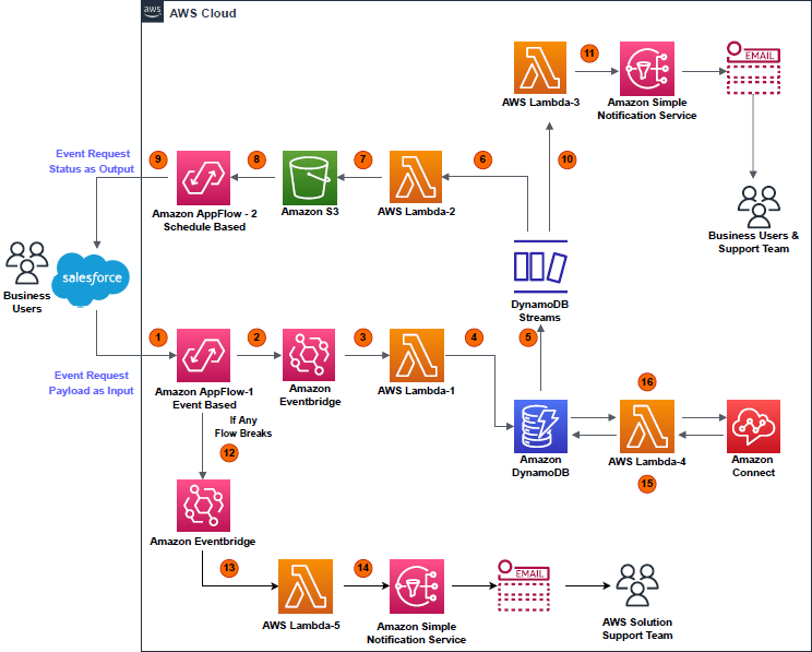
Figure 1. Architecture overview
- Event (data add or delete) occurring on a particular object in Salesforce is captured by Amazon AppFlow (event-based flow); event payload displays as “Input” in AWS environment.
- An EventBridge bus receives the “Input” payload.
- The EventBridge bus triggers the AWS Lambda (Lambda-1).
- Lambda-1 processes the “Input” payload, then performs a write operation (data add or delete) on a DynamoDB table.
- A write operation on the table triggers DynamoDB streams.
- DynamoDB stream triggers Lambda (Lambda-2).
- Lambda-2 processes the payload from DynamoDB streams. It saves the results in .csv file format, with a “Success” or “Fail” flag. This .csv file is uploaded to an S3 bucket.
- A second flow (schedule-based) is configured in Amazon AppFlow. This reads the S3 bucket at a regular interval of time to find new .csv files created by Lambda-2.
- A schedule-based flow transfers the .csv file data as an event-status output to the Salesforce object, notifying the user that their event has been successfully handled in DynamoDB table.
- In parallel, DynamoDB streams trigger Lambda (Lambda-3), which processes the payload and initiates an Amazon Simple Notification Service (Amazon SNS) notification based on the status of the event request.
- Amazon SNS sends an email to the user detailing that the event created in the Salesforce object was successfully completed in DynamoDB table.
- If any of the two flows break due to any unforeseen events, their statuses are instantly captured and streamed to an EventBridge bus.
- The EventBridge bus triggers Lambda (Lambda-5).
- Lambda-5 tries to analyze the error causing failure and tries to get the flow to a working state again. If Lambda-5 fails, it initiates an Amazon SNS email to the solution support team to manually fix the Amazon AppFlow error and get the solution active again.
- Meanwhile, whenever an Amazon Connect contact center receives a call, it triggers Lambda (Lambda-4), which holds read-only access to DynamoDB table.
- Lambda-4 fetches the data stored by Lambda-1 in DynamoDB table and provides that data to a contact center in Amazon Connect.
Prerequisites
- An AWS account with permissions to access all the required
- An active Salesforce account with administration-level permissions set
- Python 3.X version setup for developing Lambda-1 to -5
Implementation and development
1. Development steps on the Salesforce end
Note: We recommend working with a Salesforce expert. These steps can help initiate the development from Salesforce end.
a. Use the Platform Event feature to allow the data flow from Salesforce environment to AWS environment and then back to Salesforce from AWS environment using Amazon AppFlow.
b. Salesforce Connected Apps and web server flow used for integrating Amazon AppFlow with Salesforce.
c. New permissions set and new integration users are created to restrict the access to custom object.
2. Development steps on the AWS end
a. Create a new connection in Amazon AppFlow with “Salesforce” as the source
The “Client ID” and “Client Secret” of Salesforce Managed Connected App are stored in AWS Secrets Manager, which is encrypted by custom keys generated in AWS Key Management Service.
To setup an Amazon AppFlow connection with Salesforce, a stand-alone Lambda function is created using Python Boto3 API. This creates a connection in Amazon AppFlow using the “Client ID” and “Client Secret” of Salesforce connected app.
For more details regarding setting up the Salesforce connection in Amazon AppFlow, refer to the Amazon AppFlow User Guide.
b. Create new event-based input flow in Amazon AppFlow, using Salesforce as the source with the newly created connection
Select the “Salesforce events” option as per the business use case. For representation in this blog, “Telephony” is chosen as salesforce events. Select Amazon EventBridge as the destination. Create new “partner event source” for successful creation of input flow, as in Figure 2.
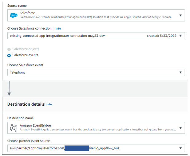
Figure 2. Configure an event-based flow in Amazon AppFlow
c. Handling large size input flow event payloads
Post successful creation of “Partner event source”, specify the S3 bucket for events that are larger than 256 KB, Amazon AppFlow sends a URL of the S3 object to the event bus instead of the event payload.
d. Configuring details for input flow
Select trigger pattern of input flow as “Run flow on event”, as shown in Figure 3.
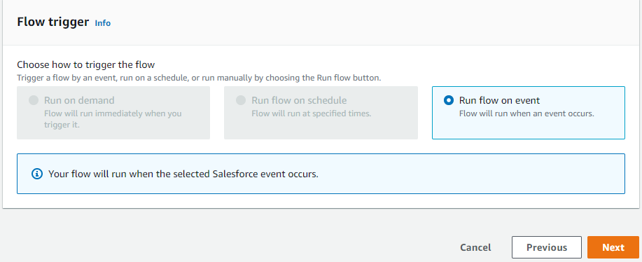
Figure 3. Trigger pattern for creating input flow
As displayed in Figure 4, we can configure data field mapping, validation rules, and filters with Amazon AppFlow. This enables us to enrich and modify event data before it is sent to the event bus. Post this, input flow create action is complete.
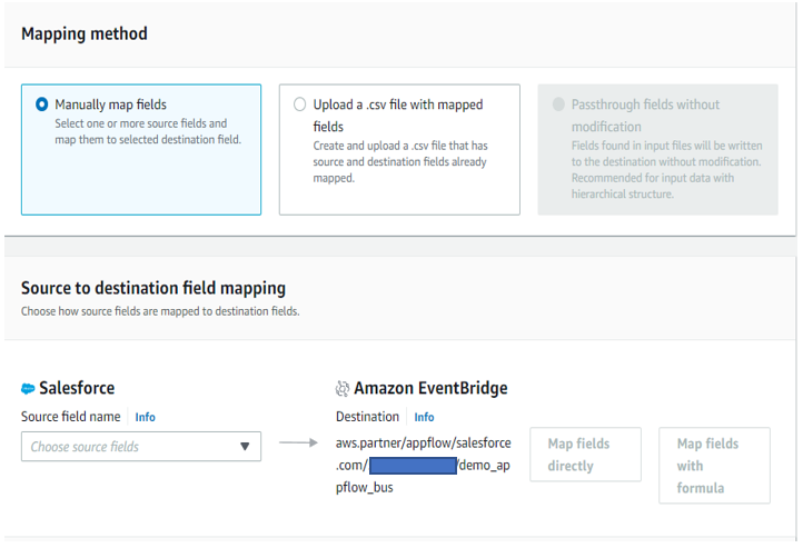
Figure 4. Mapping Salesforce object fields with Amazon EventBridge bus
e. Associating Amazon AppFlow generated partner event source with the event bus in the Amazon EventBridge dashboard
Before activating the flow, access the Amazon EventBridge console to associate the AppFlow generated partner-event-source with the event bus (Figure 5).
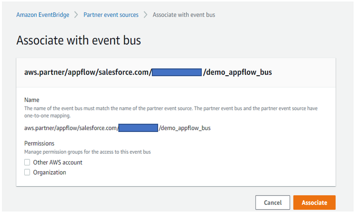
Figure 5. Associating input flow partner event source with the Amazon EventBridge bus
f. Post Amazon EventBridge bus association, activate the input flow
After associating the bus with input flow, navigate back to Amazon AppFlow console and click the “Activate flow” button for the input flow. Once active, input flow is ready to consume the event payload from Salesforce.
g. Amazon EventBridge bus triggering Lambda function
The EventBridge bus receives an event payload from the input flow and triggers Lambda (Lambda-1) to process that raw event payload and write the output results in a designated DynamoDB table. A sample of event input payload is in Figure 6. This payload content depends on the use case for which developer is working.
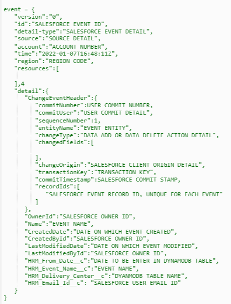
Figure 6. Input event payload sample from Salesforce
Lambda-1 adds the record-ID in the DynamoDB table, which is a unique event ID for each Salesforce event as shown in Figure 7.
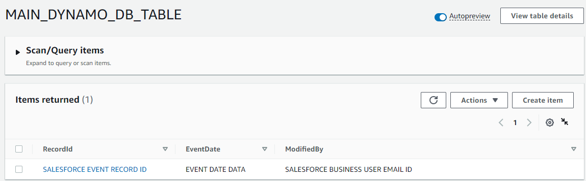
Figure 7. Data added in Amazon DynamoDB table by Lambda-1
h. Configuring DynamoDB streams
Within “Export and Streams” option in the DynamoDB table, enable the “DynamoDB stream details” and in the trigger section click on “Create trigger” option and select Lambda-2 and Lambda -3, as detailed in Figure 8.
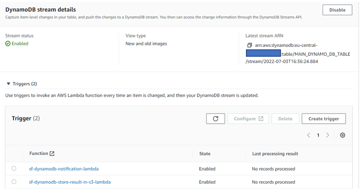
Figure 8. Configuring Amazon DynamoDB streams
Lambda-2 stores the event output results and a success flag value in a .csv file that is created for every unique event; the .csv file is uploaded to an S3 bucket with the file name structure “Salesforce event recorded-event action-timestamp.csv”. For example:
Example 1: “abcd1234-event-created- 2022-05-19-11_23_51.csv” (data added)
Example 2: “abcd1234-event-deleted- 2022-05-19-11_24_50.csv” (data deleted)
i. Create new schedule-based flow (output flow) in Amazon AppFlow
The source is the S3 bucket folder where the .csv file is uploaded by Lambda-2. Select the destination as “Salesforce”, and choose the Salesforce object that is used to create the input flow (Figure 9). Revisit Step b for reference.
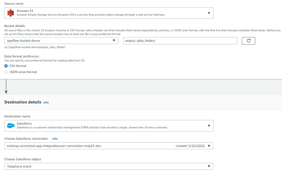
Figure 9. Configuring a schedule-based output flow
Output flow sends a response back to the same Salesforce object from which data addition/deletion event request was made. This confirms to the user that a data addition/deletion event created in Salesforce was successfully invoked in Dynamo DB table as well.
j. Error handling in output flow
In case output flow fails to write the response back to the Salesforce object, choose the option “Stop the current flow run”.
k. Configuring output flow as a run-on schedule
Output flow is a schedule-based flow that runs at specific time. Within the flow trigger window, select “Run flow on schedule”. Update the other fields, such as “Repeats”, “Every”, “Start date”, and “Starting at” per your specific needs. Within “Transfer mode”, select “Incremental transfer”. Refer to Figure 10.
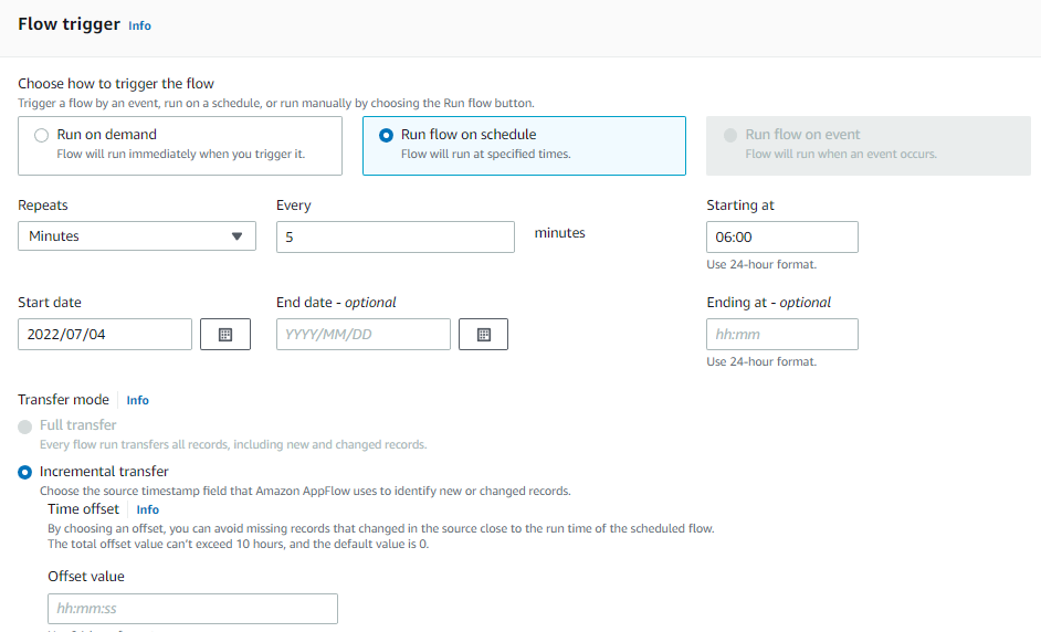
Figure 10. Trigger pattern for schedule-based output flow
l. Amazon AppFlow to Salesforce object mapping for output flow
Select Mapping method as “Manually map fields” and Destination record preference as “Upsert records”, as in Figure 11.
Output Flow will update the event record status in the Salesforce object, with success status flag value in the .csv file based on the unique “Record ID” that every Salesforce event payload contains. Once the field mapping is completed, output flow is active.
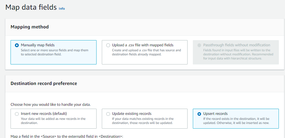
Figure 11. Manually mapping data fields with Salesforce
m. Real-time monitoring and failure handling
In case input/output flow breaks for unforeseen reasons, a rule is configured in EventBridge bus console that invokes Lambda (Lambda-5). Lambda-5 tries to handle the error and reactivate the flow. In case this action fails, Lambda sends an Amazon SNS email to the solution support team informing of the failure in Amazon AppFlow and the cause.
n. Integrating DynamoDB with Amazon Connect
Lambda (Lambda-4) is configured with contact center in Amazon Connect. As the call comes to contact center, Lambda-4 fetches the relevant data from the DynamoDB table. Amazon Connect operates per this data.
Cleanup
To avoid incurring future charges, delete any AWS resources that are no longer needed.
Conclusion
This post demonstrates the approach for developing an event-driven, serverless application that integrates DynamoDB with Salesforce using Amazon AppFlow bi-directionally. The contact center is based in Amazon Connect and functions dependent on the real-time data in a DynamoDB table—without manual intervention. The manual process can take a minimum of 24 hours, but the same action can be automatically completed using a self-service, UI-based form in the user’s Salesforce account.
This solution can be tailored depending on the business or technical requirement, differing how the data is consumed by multiple AWS services.


