This post was co-written by Soheil Moosavi, a data scientist consultant in Accenture Applied Intelligence (AAI) team, and Louis Lim, a manager in Accenture AWS Business Group.
Virtually every electric customer in the US and Canada has, at one time or another, experienced a sustained electric outage as a direct result of a tree and power line contact. According to the report from Federal Energy Regulatory Commission (FERC.gov), Electric utility companies actively work to mitigate these threats.
Vegetation Management (VM) programs represent one of the largest recurring maintenance expenses for electric utility companies in North America. Utilities and regulators generally agree that keeping trees and vegetation from conflicting with overhead conductors. It is a critical and expensive responsibility of all utility companies concerned about electric service reliability.
Vegetation management such as tree trimming and removal is essential for electricity providers to reduce unwanted outages and be rated with a low System Average Interruption Duration Index (SAIDI) score. Electricity providers are increasingly interested in identifying innovative practices and technologies to mitigate outages, streamline vegetation management activities, and maintain acceptable SAIDI scores. With the recent democratization of machine learning leveraging the power of cloud, utility companies are identifying unique ways to solve complex business problems on top of AWS. The Accenture AWS Business Group, a strategic collaboration by Accenture and AWS, helps customers accelerate their pace of innovation to deliver disruptive products and services. Learning how to machine learn helps enterprises innovate and disrupt unlocking business value.
In this blog post, you learn how Accenture and AWS collaborated to develop a machine learning solution for an electricity provider using Amazon SageMaker. The goal was to improve vegetation management and optimize program cost.
Overview of solution
VM is generally performed on a cyclical basis, prioritizing circuits solely based on the number of outages in the previous years. A more sophisticated approach is to use Light Detection and Ranging (LIDAR) and imagery from aircraft and low earth orbit (LEO) satellites with Machine Learning models, to determine where VM is needed. This provides the information for precise VM plans, but is more expensive due to cost to acquire the LIDAR and imagery data.
In this blog, we show how a machine learning (ML) solution can prioritize circuits based on the impacts of tree-related outages on the coming year’s SAIDI without using imagery data.
We demonstrate how to implement a solution that cross-references, cleans, and transforms time series data from multiple resources. This then creates features and models that predict the number of outages in the coming year, and sorts and prioritizes circuits based on their impact on the coming year’s SAIDI. We show how you use an interactive dashboard designed to browse circuits and the impact of performing VM on SAIDI reduction based on your budget.
Next, AWS Glue Crawlers are used to crawl the data from the source bucket. Glue Jobs were used to cross-reference data files to create features for modeling and data for the dashboards.
We used Jupyter Notebooks on Amazon SageMaker to train and evaluate models. The best performing model was saved as a pickle file on Amazon S3 and Glue was used to add the predicted number of outages for each circuit to the data prepared for the dashboards.
Lastly, Operations users were granted access to Amazon QuickSight dashboards, sourced data from Athena, to browse the data and graphs, while VM users were additionally granted access to directly edit the data prepared for dashboards, such as the latest VM cost for each circuit.
We used Amazon QuickSight to create interactive dashboards for the VM team members to visualize analytics and predictions. These predictions are a list of circuits prioritized based on their impact on SAIDI in the coming year. The solution allows our team to analyze the data and experiment with different models in a rapid cycle.
Modeling
We were provided with 6 years worth of data across 127 circuits. Data included VM (VM work start and end date, number of trees trimmed and removed, costs), asset (pole count, height, and materials, wire count, length, and materials, and meter count and voltage), terrain (elevation, landcover, flooding frequency, wind erodibility, soil erodibility, slope, soil water absorption, and soil loss tolerance from GIS ESRI layers), and outages (outage coordinated, dates, duration, total customer minutes, total customers affected). In addition, we collected weather data from NOAA and DarkSky datasets, including wind, gust, precipitation, temperature.
Starting with 762 records (6 years * 127 circuits) and 226 features, we performed a series of data cleaning and feature engineering tasks including:
Dropped sparse, non-variant, and non-relevant features
Capped selected outliers based on features’ distributions and percentiles
Normalized imbalanced features
Imputed missing values
Used “0” where missing value meant zero (for example, number of trees removed)
Used 3650 (equivalent to 10 years) where missing values are days for VM work (for example, days since previous tree trimming job)
Used average of values for each circuit when applicable, and average of values across all circuits for circuits with no existing values (for example, pole mean height)
Merged conceptually relevant features
Created new features such as ratios (for example, tree trim cost per trim) and combinations(for example, % of land cover for low and medium intensity areas combined)
After further dropping highly correlated features to remove multi-collinearity for our models, we were left with 72 features for model development. The following diagram shows a high-level overview data partitioning and number of outages prediction.
Our best performing model out of Gradient Boosting Trees, Random Forest, and Feed Forward Neural Networks was Elastic Net, with Mean Absolute Error of 6.02 when using a combination of only 10 features. Elastic Net is appropriate for smaller sample for this dataset, good at feature selection, likely to generalize on a new dataset, and consistently showed a lower error rate. Exponential expansion of features showed small improvements in predictions, but we kept the non-expanded version due to better interpretability.
When analyzing the model performance, predictions were more accurate for circuits with lower outage count, and models suffered from under-predicting when the number of outages was high. This is due to having few circuits with a high number of outages for the model to learn from.
The following chart below shows the importance of each feature used in the model. An error of 6.02 means on average we over or under predict six outages for each circuit.
Dashboard
We designed two types of interactive dashboards for the VM team to browse results and predictions. The first set of dashboards show historical or predicted outage counts for each circuit on a geospatial map. Users can further filter circuits based on criteria such as the number of days since VM, as shown in the following screenshot.
The second type of dashboard shows predicted post-VM SAIDI on the y-axis and VM cost on the x-axis. This dashboard is used by the client to determine the reduction in SAIDI based on available VM budget for the year and dispatch the VM crew accordingly. Clients can also upload a list of update VM cost for each circuit, and the graph will automatically readjust.
Conclusion
This solution for Vegetation management demonstrates how we used Amazon SageMaker to train and evaluate machine learning models. Using this solution an Electric Utility can save time and cost, and scale easily to include more circuits within a set VM budget. We demonstrated how a utility can leverage machine learning to predict unwanted outages and also maintain vegetation, without incurring the cost of high-resolution imagery.
Further, to improve these predictions we recommend:
A yearly collection of asset and terrain data (if data is only available for the most recent year, it is impossible for models to learn from each years’ changes),
Collection of VM data per month per location (if current data is collected only at the end of each VM cycle and only per circuit, monthly, and subcircuit modeling is impossible), and
Purchasing LiDAR imagery or tree inventory data to include features such as tree density, height, distance to wires, and more.
Accelerating Innovation with the Accenture AWS Business Group (AABG)
By working with the Accenture AWS Business Group (AABG), you can learn from the resources, technical expertise, and industry knowledge of two leading innovators, helping you accelerate the pace of innovation to deliver disruptive products and services. The AABG helps customers ideate and innovate cloud solutions with customers through rapid prototype development.
Connect with our team at [email protected] to learn and accelerate how to use machine learning in your products and services.
Field Notes provides hands-on technical guidance from AWS Solutions Architects, consultants, and technical account managers, based on their experiences in the field solving real-world business problems for customers.
Soheil Moosavi
Louis Lim is a manager in Accenture AWS Business Group, his team focus on helping enterprises to explore the art of possible through rapid prototyping and cloud-native solution.
Micro Focus – AWS Advanced Technology Parnter, they are a global infrastructure software company with 40 years of experience in delivering and supporting enterprise software.
We have seen mainframe customers often encounter scalability constraints, and they can’t support their development and test workforce to the scale required to support business requirements. These constraints can lead to delays, reduce product or feature releases, and make them unable to respond to market requirements. Furthermore, limits in capacity and scale often affect the quality of changes deployed, and are linked to unplanned or unexpected downtime in products or services.
The conventional approach to address these constraints is to scale up, meaning to increase MIPS/MSU capacity of the mainframe hardware available for development and testing. The cost of this approach, however, is excessively high, and to ensure time to market, you may reject this approach at the expense of quality and functionality. If you’re wrestling with these challenges, this post is written specifically for you.
In the APG, we introduce DevOps automation and AWS CI/CD architecture to support mainframe application development. Our solution enables you to embrace both Test Driven Development (TDD) and Behavior Driven Development (BDD). Mainframe developers and testers can automate the tests in CI/CD pipelines so they’re repeatable and scalable. To speed up automated mainframe application tests, the solution uses team pipelines to run functional and integration tests frequently, and uses systems test pipelines to run comprehensive regression tests on demand. For more information about the pipelines, see Mainframe Modernization: DevOps on AWS with Micro Focus.
In this post, we focus on how to automate and scale mainframe application tests in AWS. We show you how to use AWS services and Micro Focus products to automate mainframe application tests with best practices. The solution can scale your mainframe application CI/CD pipeline to run thousands of tests in AWS within minutes, and you only pay a fraction of your current on-premises cost.
The following diagram illustrates the solution architecture.
Figure: Mainframe DevOps On AWS Architecture Overview
Best practices
Before we get into the details of the solution, let’s recap the following mainframe application testing best practices:
Create a “test first” culture by writing tests for mainframe application code changes
Automate preparing and running tests in the CI/CD pipelines
Provide fast and quality feedback to project management throughout the SDLC
Assess and increase test coverage
Scale your test’s capacity and speed in line with your project schedule and requirements
Automated smoke test
In this architecture, mainframe developers can automate running functional smoke tests for new changes. This testing phase typically “smokes out” regression of core and critical business functions. You can achieve these tests using tools such as py3270 with x3270 or Robot Framework Mainframe 3270 Library.
The following code shows a feature test written in Behave and test step using py3270:
# home_loan_calculator.feature
Feature: calculate home loan monthly repayment
the bankdemo application provides a monthly home loan repayment caculator
User need to input into transaction of home loan amount, interest rate and how many years of the loan maturity.
User will be provided an output of home loan monthly repayment amount
Scenario Outline: As a customer I want to calculate my monthly home loan repayment via a transaction
Given home loan amount is <amount>, interest rate is <interest rate> and maturity date is <maturity date in months> months
When the transaction is submitted to the home loan calculator
Then it shall show the monthly repayment of <monthly repayment>
Examples: Homeloan
| amount | interest rate | maturity date in months | monthly repayment |
| 1000000 | 3.29 | 300 | $4894.31 |
# home_loan_calculator_steps.py
import sys, os
from py3270 import Emulator
from behave import *
@given("home loan amount is {amount}, interest rate is {rate} and maturity date is {maturity_date} months")
def step_impl(context, amount, rate, maturity_date):
context.home_loan_amount = amount
context.interest_rate = rate
context.maturity_date_in_months = maturity_date
@when("the transaction is submitted to the home loan calculator")
def step_impl(context):
# Setup connection parameters
tn3270_host = os.getenv('TN3270_HOST')
tn3270_port = os.getenv('TN3270_PORT')
# Setup TN3270 connection
em = Emulator(visible=False, timeout=120)
em.connect(tn3270_host + ':' + tn3270_port)
em.wait_for_field()
# Screen login
em.fill_field(10, 44, 'b0001', 5)
em.send_enter()
# Input screen fields for home loan calculator
em.wait_for_field()
em.fill_field(8, 46, context.home_loan_amount, 7)
em.fill_field(10, 46, context.interest_rate, 7)
em.fill_field(12, 46, context.maturity_date_in_months, 7)
em.send_enter()
em.wait_for_field()
# collect monthly replayment output from screen
context.monthly_repayment = em.string_get(14, 46, 9)
em.terminate()
@then("it shall show the monthly repayment of {amount}")
def step_impl(context, amount):
print("expected amount is " + amount.strip() + ", and the result from screen is " + context.monthly_repayment.strip())
assert amount.strip() == context.monthly_repayment.strip()
To run this functional test in Micro Focus Enterprise Test Server (ETS), we use AWS CodeBuild.
In the CodeBuild project, we need to create a buildspec to orchestrate the commands for preparing the Micro Focus Enterprise Test Server CICS environment and issue the test command. In the buildspec, we define the location for CodeBuild to look for test reports and upload them into the CodeBuild report group. The following buildspec code uses custom scripts DeployES.ps1 and StartAndWait.ps1 to start your CICS region, and runs Python Behave BDD tests:
version: 0.2
phases:
build:
commands:
- |
# Run Command to start Enterprise Test Server
CD C:\
.\DeployES.ps1
.\StartAndWait.ps1
py -m pip install behave
Write-Host "waiting for server to be ready ..."
do {
Write-Host "..."
sleep 3
} until(Test-NetConnection 127.0.0.1 -Port 9270 | ? { $_.TcpTestSucceeded } )
CD C:\tests\features
MD C:\tests\reports
$Env:Path += ";c:\wc3270"
$address=(Get-NetIPAddress -AddressFamily Ipv4 | where { $_.IPAddress -Match "172\.*" })
$Env:TN3270_HOST = $address.IPAddress
$Env:TN3270_PORT = "9270"
behave.exe --color --junit --junit-directory C:\tests\reports
reports:
bankdemo-bdd-test-report:
files:
- '**/*'
base-directory: "C:\\tests\\reports"
In the smoke test, the team may run both unit tests and functional tests. Ideally, these tests are better to run in parallel to speed up the pipeline. In AWS CodePipeline, we can set up a stage to run multiple steps in parallel. In our example, the pipeline runs both BDD tests and Robot Framework (RPA) tests.
The following CloudFormation code snippet runs two different tests. You use the same RunOrder value to indicate the actions run in parallel.
The following screenshot shows the example actions on the CodePipeline console that use the preceding code.
Figure – Screenshot of CodePipeine parallel execution tests
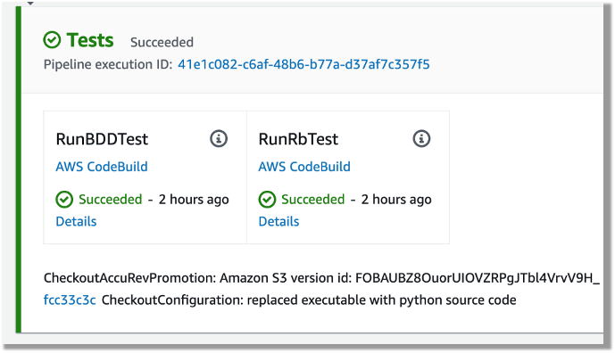
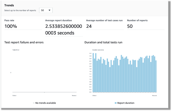
Both DBB and RPA tests produce jUnit format reports, which CodeBuild can ingest and show on the CodeBuild console. This is a great way for project management and business users to track the quality trend of an application. The following screenshot shows the CodeBuild report generated from the BDD tests.
Figure – CodeBuild report generated from the BDD tests
Automated regression tests
After you test the changes in the project team pipeline, you can automatically promote them to another stream with other team members’ changes for further testing. The scope of this testing stream is significantly more comprehensive, with a greater number and wider range of tests and higher volume of test data. The changes promoted to this stream by each team member are tested in this environment at the end of each day throughout the life of the project. This provides a high-quality delivery to production, with new code and changes to existing code tested together with hundreds or thousands of tests.
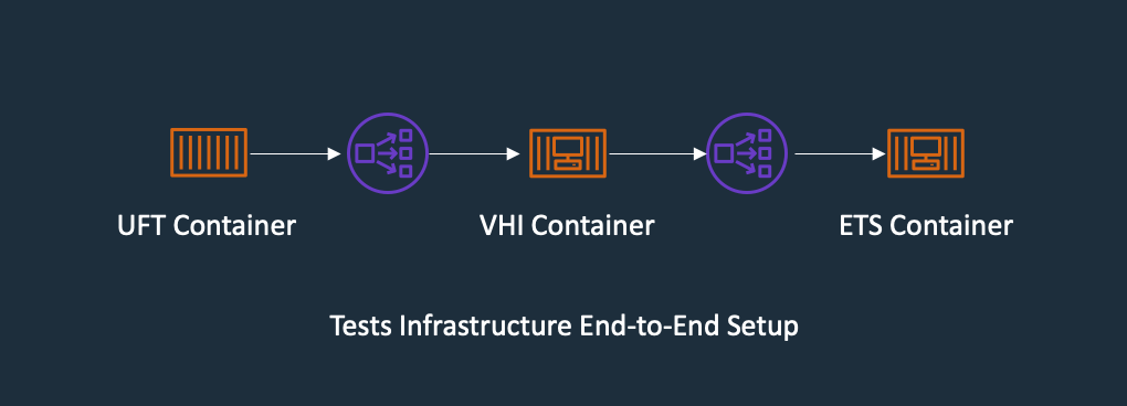
In enterprise architecture, it’s commonplace to see an application client consuming web services APIs exposed from a mainframe CICS application. One approach to do regression tests for mainframe applications is to use Micro Focus Verastream Host Integrator (VHI) to record and capture 3270 data stream processing and encapsulate these 3270 data streams as business functions, which in turn are packaged as web services. When these web services are available, they can be consumed by a test automation product, which in our environment is Micro Focus UFT One. This uses the Verastream server as the orchestration engine that translates the web service requests into 3270 data streams that integrate with the mainframe CICS application. The application is deployed in Micro Focus Enterprise Test Server.
The following diagram shows the end-to-end testing components.
Figure – Regression Test Infrastructure end-to-end Setup
To ensure we have the coverage required for large mainframe applications, we sometimes need to run thousands of tests against very large production volumes of test data. We want the tests to run faster and complete as soon as possible so we reduce AWS costs—we only pay for the infrastructure when consuming resources for the life of the test environment when provisioning and running tests.
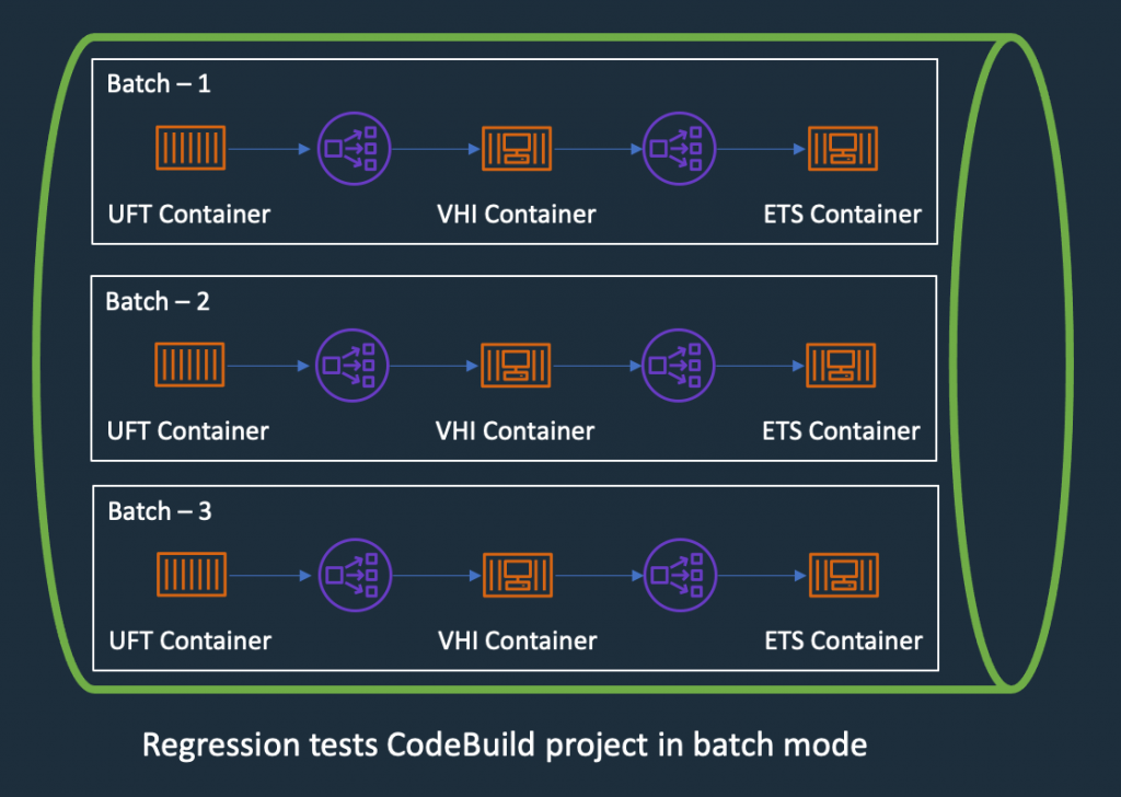
Therefore, the design of the test environment needs to scale out. The batch feature in CodeBuild allows you to run tests in batches and in parallel rather than serially. Furthermore, our solution needs to minimize interference between batches, a failure in one batch doesn’t affect another running in parallel. The following diagram depicts the high-level design, with each batch build running in its own independent infrastructure. Each infrastructure is launched as part of test preparation, and then torn down in the post-test phase.
Figure – Regression Tests in CodeBuoild Project setup to use batch mode
Building and deploying regression test components
Following the design of the parallel regression test environment, let’s look at how we build each component and how they are deployed. The followings steps to build our regression tests use a working backward approach, starting from deployment in the Enterprise Test Server:
Create a batch build in CodeBuild.
Deploy to Enterprise Test Server.
Deploy the VHI model.
Deploy UFT One Tests.
Integrate UFT One into CodeBuild and CodePipeline and test the application.
Creating a batch build in CodeBuild
We update two components to enable a batch build. First, in the CodePipeline CloudFormation resource, we set BatchEnabled to be true for the test stage. The UFT One test preparation stage uses the CloudFormation template to create the test infrastructure. The following code is an example of the AWS CloudFormation snippet with batch build enabled:
Second, in the buildspec configuration of the test stage, we provide a build matrix setting. We use the custom environment variable TEST_BATCH_NUMBER to indicate which set of tests runs in each batch. See the following code:
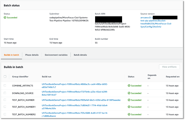
After setting up the batch build, CodeBuild creates multiple batches when the build starts. The following screenshot shows the batches on the CodeBuild console.
Figure – Regression tests Codebuild project ran in batch mode
Deploying to Enterprise Test Server
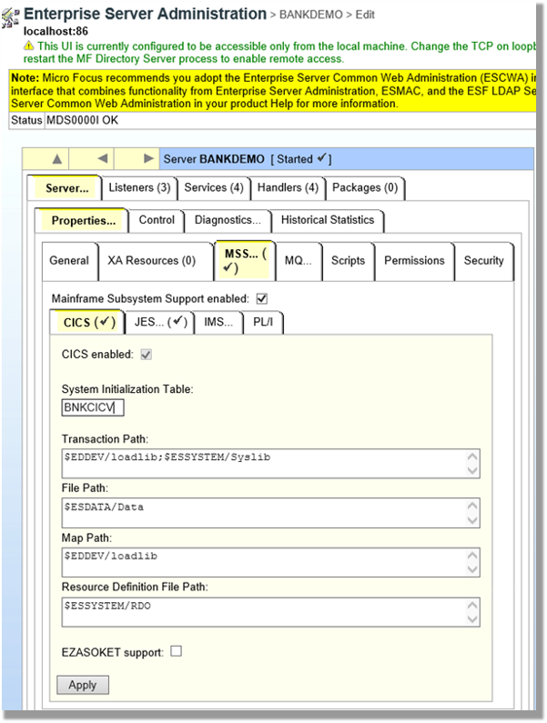
ETS is the transaction engine that processes all the online (and batch) requests that are initiated through external clients, such as 3270 terminals, web services, and websphere MQ. This engine provides support for various mainframe subsystems, such as CICS, IMS TM and JES, as well as code-level support for COBOL and PL/I. The following screenshot shows the Enterprise Test Server administration page.
Figure – Enterprise Server Administrator window
In this mainframe application testing use case, the regression tests are CICS transactions, initiated from 3270 requests (encapsulated in a web service). For more information about Enterprise Test Server, see the Enterprise Test Server and Micro Focus websites.
In the regression pipeline, after the stage of mainframe artifact compiling, we bake in the artifact into an ETS Docker container and upload the image to an Amazon ECR repository. This way, we have an immutable artifact for all the tests.
During each batch’s test preparation stage, a CloudFormation stack is deployed to create an Amazon ECS service on Windows EC2. The stack uses a Network Load Balancer as an integration point for the VHI’s integration.
The following code is an example of the CloudFormation snippet to create an Amazon ECS service using an Enterprise Test Server Docker image:
In this architecture, the VHI is a bridge between mainframe and clients.
We use the VHI designer to capture the 3270 data streams and encapsulate the relevant data streams into a business function. We can then deliver this function as a web service that can be consumed by a test management solution, such as Micro Focus UFT One.
The following screenshot shows the setup for getCheckingDetails in VHI. Along with this procedure we can also see other procedures (eg calcCostLoan) defined that get generated as a web service. The properties associated with this procedure are available on this screen to allow for the defining of the mapping of the fields between the associated 3270 screens and exposed web service.
Figure – Setup for getCheckingDetails in VHI
The following screenshot shows the editor for this procedure and is initiated by the selection of the Procedure Editor. This screen presents the 3270 screens that are involved in the business function that will be generated as a web service.
Figure – VHI designer Procedure Editor shows the procedure
After you define the required functional web services in VHI designer, the resultant model is saved and deployed into a VHI Docker image. We use this image and the associated model (from VHI designer) in the pipeline outlined in this post.
For more information about VHI, see the VHI website.
The pipeline contains two steps to deploy a VHI service. First, it installs and sets up the VHI models into a VHI Docker image, and it’s pushed into Amazon ECR. Second, a CloudFormation stack is deployed to create an Amazon ECS Fargate service, which uses the latest built Docker image. In AWS CloudFormation, the VHI ECS task definition defines an environment variable for the ETS Network Load Balancer’s DNS name. Therefore, the VHI can bootstrap and point to an ETS service. In the VHI stack, it uses a Network Load Balancer as an integration point for UFT One test integration.
The following code is an example of a ECS Task Definition CloudFormation snippet that creates a VHI service in Amazon ECS Fargate and integrates it with an ETS server:
UFT One is a test client that uses each of the web services created by the VHI designer to orchestrate running each of the associated business functions. Parameter data is supplied to each function, and validations are configured against the data returned. Multiple test suites are configured with different business functions with the associated data.
The following screenshot shows the test suite API_Bankdemo3, which is used in this regression test process.
Figure – API_Bankdemo3 in UFT One Test Editor Console
The last step is to integrate UFT One into CodeBuild and CodePipeline to test our mainframe application. First, we set up CodeBuild to use a UFT One container. The Docker image is available in Docker Hub. Then we author our buildspec. The buildspec has the following three phrases:
Setting up a UFT One license and deploying the test infrastructure
Starting the UFT One test suite to run regression tests
Tearing down the test infrastructure after tests are complete
The following code is an example of a buildspec snippet in the pre_build stage. The snippet shows the command to activate the UFT One license:
Because ETS and VHI are both deployed with a load balancer, the build detects when the load balancers become healthy before starting the tests. The following AWS CLI commands detect the load balancer’s target group health:
The next release of Micro Focus UFT One (November or December 2020) will provide an exit status to indicate a test’s success or failure.
When the tests are complete, the post_build stage tears down the test infrastructure. The following AWS CLI command tears down the CloudFormation stack:
At the end of the build, the buildspec is set up to upload UFT One test reports as an artifact into Amazon Simple Storage Service (Amazon S3). The following screenshot is the example of a test report in HTML format generated by UFT One in CodeBuild and CodePipeline.
Figure – UFT One HTML report
A new release of Micro Focus UFT One will provide test report formats supported by CodeBuild test report groups.
Conclusion
In this post, we introduced the solution to use Micro Focus Enterprise Suite, Micro Focus UFT One, Micro Focus VHI, AWS developer tools, and Amazon ECS containers to automate provisioning and running mainframe application tests in AWS at scale.
The on-demand model allows you to create the same test capacity infrastructure in minutes at a fraction of your current on-premises mainframe cost. It also significantly increases your testing and delivery capacity to increase quality and reduce production downtime.
A demo of the solution is available in AWS Partner Micro Focus website AWS Mainframe CI/CD Enterprise Solution. If you’re interested in modernizing your mainframe applications, please visit Micro Focus and contact AWS mainframe business development at [email protected].
Peter has been with Micro Focus for almost 30 years, in a variety of roles and geographies including Technical Support, Channel Sales, Product Management, Strategic Alliances Management and Pre-Sales, primarily based in Europe but for the last four years in Australia and New Zealand. In his current role as Pre-Sales Manager, Peter is charged with driving and supporting sales activity within the Application Modernization and Connectivity team, based in Melbourne.
Leo Ervin
Leo Ervin is a Senior Solutions Architect working with Micro Focus Enterprise Solutions working with the ANZ team. After completing a Mathematics degree Leo started as a PL/1 programming with a local insurance company. The next step in Leo’s career involved consulting work in PL/1 and COBOL before he joined a start-up company as a technical director and partner. This company became the first distributor of Micro Focus software in the ANZ region in 1986. Leo’s involvement with Micro Focus technology has continued from this distributorship through to today with his current focus on cloud strategies for both DevOps and re-platform implementations.
Kevin Yung
Kevin is a Senior Modernization Architect in AWS Professional Services Global Mainframe and Midrange Modernization (GM3) team. Kevin currently is focusing on leading and delivering mainframe and midrange applications modernization for large enterprise customers.
You can now send logs from AWS Lambda functions directly to a destination of your choice using AWS Lambda Extensions. Lambda Extensions are a new way for monitoring, observability, security, and governance tools to easily integrate with AWS Lambda. For more information, see “Introducing AWS Lambda Extensions – In preview”.
To help you troubleshoot failures in Lambda functions, AWS Lambda automatically captures and streams logs to Amazon CloudWatch Logs. This stream contains the logs that your function code and extensions generate, in addition to logs the Lambda service generates as part of the function invocation.
Previously, to send logs to a custom destination, you typically configure and operate a CloudWatch Log Group subscription. A different Lambda function forwards logs to the destination of your choice.
Logging tools, running as Lambda extensions, can now receive log streams directly from within the Lambda execution environment, and send them to any destination. This makes it even easier for you to use your preferred extensions for diagnostics.
Today, you can use extensions to send logs to Coralogix, Datadog, Honeycomb, Lumigo, New Relic, and Sumo Logic.
Overview
To receive logs, extensions subscribe using the new Lambda Logs API.
Lambda Logs API
The Lambda service then streams the logs directly to the extension. The extension can then process, filter, and route them to any preferred destination. Lambda still sends the logs to CloudWatch Logs.
Logging extensions from AWS Lambda Ready Partners and AWS Partners available at launch
Today, you can use logging extensions with the following tools:
The Datadog extension now makes it easier than ever to collect your serverless application logs for visualization, analysis, and archival. Paired with Datadog’s AWS integration, end-to-end distributed tracing, and real-time enhanced AWS Lambda metrics, you can proactively detect and resolve serverless issues at any scale.
Lumigo provides monitoring and debugging for modern cloud applications. With the open source extension from Lumigo, you can send Lambda function logs directly to an S3 bucket, unlocking new post processing use cases.
New Relic enables you to efficiently monitor, troubleshoot, and optimize your Lambda functions. New Relic’s extension allows you send your Lambda service platform logs directly to New Relic’s unified observability platform, allowing you to quickly visualize data with minimal latency and cost.
Coralogix is a log analytics and cloud security platform that empowers thousands of companies to improve security and accelerate software delivery, allowing you to get deep insights without paying for the noise. Coralogix can now read Lambda function logs and metrics directly, without using Cloudwatch or S3, reducing the latency, and cost of observability.
Honeycomb is a powerful observability tool that helps you debug your entire production app stack. Honeycomb’s extension decreases the overhead, latency, and cost of sending events to the Honeycomb service, while increasing reliability.
The Sumo Logic extension enables you to get instant visibility into the health and performance of your mission-critical applications using AWS Lambda. With this extension and Sumo Logic’s continuous intelligence platform, you can now ensure that all your Lambda functions are running as expected, by analyzing function, platform, and extension logs to quickly identify and remediate errors and exceptions.
You can also build and use your own logging extensions to integrate your organization’s tooling.
Showing a logging extension to send logs directly to S3
To set up the example, visit the GitHub repo and follow the instructions in the README.md file.
The example extension runs a local HTTP endpoint listening for HTTP POST events. Lambda delivers log batches to this endpoint. The example creates an S3 bucket to store the logs. A Lambda function is configured with an environment variable to specify the S3 bucket name. Lambda streams the logs to the extension. The extension copies the logs to the S3 bucket.
Lambda environment variable specifying S3 bucket
The extension uses the Extensions API to register for INVOKE and SHUTDOWN events. The extension, using the Logs API, then subscribes to receive platform and function logs, but not extension logs.
As the example is an asynchronous system, logs for one invoke may be processed during the next invocation. Logs for the last invoke may be processed during the SHUTDOWN event.
Testing the function from the Lambda console, Lambda sends logs to CloudWatch Logs. The logs stream shows logs from the platform, function, and extension.
Lambda logs visible in CloudWatch Logs
The logging extension also receives the log stream directly from Lambda, and copies the logs to S3.
Browsing to the S3 bucket, the log files are available.
S3 bucket containing copied logs.
Downloading the file shows the log lines. The log contains the same platform and function logs, but not the extension logs, as specified during the subscription.
HTTP – Logs are delivered to a local HTTP endpoint through PUT or POST, as an array of records in JSON format. http://sandbox:${PORT}/${PATH}. The $PATH parameter is optional.
AWS recommends using an HTTP endpoint over TCP because HTTP tracks successful delivery of the log messages to the local endpoint that the extension sets up.
Once the endpoint is running, extensions use the Logs API to subscribe to any of three different logs streams:
Function logs that are generated by the Lambda function.
Lambda service platform logs (such as the START, END, and REPORT logs in CloudWatch Logs).
Extension logs that are generated by extension code.
The Lambda service then sends logs to endpoint subscribers inside of the execution environment only.
Even if an extension subscribes to one or more log streams, Lambda continues to send all logs to CloudWatch.
Performance considerations
Extensions share resources with the function, such as CPU, memory, disk storage, and environment variables. They also share permissions, using the same AWS Identity and Access Management (IAM) role as the function.
Log subscriptions consume memory resources as each subscription opens a new memory buffer to store the logs. This memory usage counts towards memory consumed within the Lambda execution environment.
What happens if Lambda cannot deliver logs to an extension?
The Lambda service stores logs before sending to CloudWatch Logs and any subscribed extensions. If Lambda cannot deliver logs to the extension, it automatically retries with backoff. If the log subscriber crashes, Lambda restarts the execution environment. The logs extension re-subscribes, and continues to receive logs.
When using an HTTP endpoint, Lambda continues to deliver logs from the last acknowledged delivery. With TCP, the extension may lose logs if an extension or the execution environment fails.
The Lambda service buffers logs in memory before delivery. The buffer size is proportional to the buffering configuration used in the subscription request. If an extension cannot process the incoming logs quickly enough, the buffer fills up. To reduce the likelihood of an out of memory event due to a slow extension, the Lambda service drops records and adds a platform.logsDropped log record to the affected extension to indicate the number of dropped records.
Disabling logging to CloudWatch Logs
Lambda continues to send logs to CloudWatch Logs even if extensions subscribe to the logs stream.
To disable logging to CloudWatch Logs for a particular function, you can amend the Lambda execution role to remove access to CloudWatch Logs.
Logs are no longer delivered to CloudWatch Logs for functions using this role, but are still streamed to subscribed extensions. You are no longer billed for CloudWatch logging for these functions.
Pricing
Logging extensions, like other extensions, share the same billing model as Lambda functions. When using Lambda functions with extensions, you pay for requests served and the combined compute time used to run your code and all extensions, in 100 ms increments. To learn more about the billing for extensions, visit the Lambda FAQs page.
Conclusion
Lambda extensions enable you to extend the Lambda service to more easily integrate with your favorite tools for monitoring, observability, security, and governance.
Extensions can now subscribe to receive log streams directly from the Lambda service, in addition to CloudWatch Logs. Today, you can install a number of available logging extensions from AWS Lambda Ready Partners and AWS Partners. Extensions make it easier to use your existing tools with your serverless applications.
To try the S3 demo logging extension, follow the instructions in the README.md file in the GitHub repository.
Extensions are now available in preview in all commercial regions other than the China regions.
Last year, we launched Virtual Private Cloud (VPC) Ingress Routing to allow routing of all incoming and outgoing traffic to/from an Internet Gateway (IGW) or Virtual Private Gateway (VGW) to the Elastic Network Interface of a specific Amazon Elastic Compute Cloud (EC2) instance. With VPC Ingress Routing, you can now configure your VPC to send all […]
AWS Lambda is announcing a preview of Lambda Extensions, a new way to easily integrate Lambda with your favorite monitoring, observability, security, and governance tools. Extensions enable tools to integrate deeply into the Lambda execution environment to control and participate in Lambda’s lifecycle. This simplified experience makes it easier for you to use your preferred tools across your application portfolio today.
In this post I explain how Lambda extensions work, the changes to the Lambda lifecycle, and how to build an extension. To learn how to use extensions with your functions, see the companion blog post “Introducing AWS Lambda extensions”.
Extensions are built using the new Lambda Extensions API, which provides a way for tools to get greater control during function initialization, invocation, and shut down. This API builds on the existing Lambda Runtime API, which enables you to bring custom runtimes to Lambda.
You can use extensions from AWS, AWS Lambda Ready Partners, and open source projects for use-cases such as application performance monitoring, secrets management, configuration management, and vulnerability detection. You can also build your own extensions to integrate your own tooling using the Extensions API.
There are extensions available today for AppDynamics, Check Point, Datadog, Dynatrace, Epsagon, HashiCorp, Lumigo, New Relic, Thundra, Splunk, AWS AppConfig, and Amazon CloudWatch Lambda Insights. For more details on these, see “Introducing AWS Lambda extensions”.
The Lambda execution environment
Lambda functions run in a sandboxed environment called an execution environment. This isolates them from other functions and provides the resources, such as memory, specified in the function configuration.
Lambda automatically manages the lifecycle of compute resources so that you pay for value. Between function invocations, the Lambda service freezes the execution environment. It is thawed if the Lambda service needs the execution environment for subsequent invocations.
Previously, only the runtime process could influence the lifecycle of the execution environment. It would communicate with the Runtime API, which provides an HTTP API endpoint within the execution environment to communicate with the Lambda service.
Lambda and Runtime API
The runtime uses the API to request invocation events from Lambda and deliver them to the function code. It then informs the Lambda service when it has completed processing an event. The Lambda service then freezes the execution environment.
The runtime process previously exposed two distinct phases in the lifecycle of the Lambda execution environment: Init and Invoke.
1. Init: During the Init phase, the Lambda service initializes the runtime, and then runs the function initialization code (the code outside the main handler). The Init phase happens either during the first invocation, or in advance if Provisioned Concurrency is enabled.
2. Invoke: During the invoke phase, the runtime requests an invocation event from the Lambda service via the Runtime API, and invokes the function handler. It then returns the function response to the Runtime API.
After the function runs, the Lambda service freezes the execution environment and maintains it for some time in anticipation of another function invocation.
If the Lambda function does not receive any invokes for a period of time, the Lambda service shuts down and removes the environment.
Previous Lambda lifecycle
With the addition of the Extensions API, extensions can now influence, control, and participate in the lifecycle of the execution environment. They can use the Extensions API to influence when the Lambda service freezes the execution environment.
AWS Lambda execution environment with the Extensions API
Extensions are initialized before the runtime and the function. They then continue to run in parallel with the function, get greater control during function invocation, and can run logic during shut down.
Extensions allow integrations with the Lambda service by introducing the following changes to the Lambda lifecycle:
An updated Init phase. There are now three discrete Init tasks: extensions Init, runtime Init, and function Init. This creates an order where extensions and the runtime can perform setup tasks before the function code runs.
Greater control during invocation. During the invoke phase, as before, the runtime requests the invocation event and invokes the function handler. In addition, extensions can now request lifecycle events from the Lambda service. They can run logic in response to these lifecycle events, and respond to the Lambda service when they are done. The Lambda service freezes the execution environment when it hears back from the runtime and all extensions. In this way, extensions can influence the freeze/thaw behavior.
Shutdown phase: we are now exposing the shutdown phase to let extensions stop cleanly when the execution environment shuts down. The Lambda service sends a shut down event, which tells the runtime and extensions that the environment is about to be shut down.
New Lambda lifecycle with extensions
Each Lambda lifecycle phase starts with an event from the Lambda service to the runtime and all registered extensions. The runtime and extensions signal that they have completed by requesting the Next invocation event from the Runtime and Extensions APIs. Lambda freezes the execution environment and all extensions when there are no pending events.
Lambda lifecycle for execution environment, runtime, extensions, and function.png
For more information on the lifecycle phases and the Extensions API, see the documentation.
How are extensions delivered and run?
You deploy extensions as Lambda layers, which are ZIP archives containing shared libraries or other dependencies.
When the Lambda service starts the function execution environment, it extracts the extension files from the Lambda layer into the /opt directory. Lambda then looks for any extensions in the /opt/extensions directory and starts initializing them. Extensions need to be executable as binaries or scripts. As the function code directory is read-only, extensions cannot modify function code.
Extensions can run in either of two modes, internal and external.
Internal extensions run as part of the runtime process, in-process with your code. They are not separate processes. Internal extensions allow you to modify the startup of the runtime process using language-specific environment variables and wrapper scripts. You can use language-specific environment variables to add options and tools to the runtime for Java Correto 8 and 11, Node.js 10 and 12, and .NET Core 3.1. Wrapper scripts allow you to delegate the runtime startup to your script to customize the runtime startup behavior. You can use wrapper scripts with Node.js 10 and 12, Python 3.8, Ruby 2.7, Java 8 and 11, and .NET Core 3.1. For more information, see “Modifying-the-runtime-environment”.
External extensions allow you to run separate processes from the runtime but still within the same execution environment as the Lambda function. External extensions can start before the runtime process, and can continue after the runtime shuts down. External extensions work with Node.js 10 and 12, Python 3.7 and 3.8, Ruby 2.5 and 2.7, Java Corretto 8 and 11, .NET Core 3.1, and custom runtimes.
External extensions can be written in a different language to the function. We recommend implementing external extensions using a compiled language as a self-contained binary. This makes the extension compatible with all of the supported runtimes. If you use a non-compiled language, ensure that you include a compatible runtime in the extension.
Extensions run in the same execution environment as the function, so share resources such as CPU, memory, and disk storage with the function. They also share environment variables, in addition to permissions, using the same AWS Identity and Access Management (IAM) role as the function.
For more details on resources, security, and performance with extensions, see the companion blog post “Introducing AWS Lambda extensions”.
For example extensions and wrapper scripts to help you build your own extensions, see the GitHub repository.
Showing extensions in action
The demo shows how external extensions integrate deeply with functions and the Lambda runtime. The demo creates an example Lambda function with a single extension using either the AWS CLI, or AWS SAM.
The example shows how an external extension can start before the runtime, run during the Lambda function invocation, and shut down after the runtime shuts down.
To set up the example, visit the GitHub repo, and follow the instructions in the README.md file.
The example Lambda function uses the custom provided.al2 runtime based on Amazon Linux 2. Using the custom runtime helps illustrate in more detail how the Lambda service, Runtime API, and the function communicate. The extension is delivered using a Lambda layer.
The runtime, function, and extension, log their status events to Amazon CloudWatch Logs. The extension initializes as a separate process and waits to receive the function invocation event from the Extensions API. It then sleeps for 5 seconds before calling the API again to register to receive the next event. The extension sleep simulates the processing of a parallel process. This could, for example, collect telemetry data to send to an external observability service.
When the Lambda function is invoked, the extension, runtime and function perform the following steps. I walk through the steps using the log output.
1. The Lambda service adds the configured extension Lambda layer. It then searches the /opt/extensions folder, and finds an extension called extension1.sh. The extension executable launches before the runtime initializes. It registers with the Extensions API to receive INVOKE and SHUTDOWN events using the following API call.
Runtime and extension call APIs to get the next event
4. The Lambda service receives an invocation event. It sends the event payload to the runtime using the Runtime API. It sends an event to the extension informing it about the invocation, using the Extensions API.
Runtime and extension receive event
5. The runtime invokes the function handler. The function receives the event payload.
Runtime invokes handler
6. The function runs the handler code. The Lambda runtime receives back the function response and sends it back to the Runtime API with the following API call.
curl -sS -X POST "http://${AWS_LAMBDA_RUNTIME_API}/2018-06-01/runtime/invocation/$REQUEST_ID/response" -d "$RESPONSE" > $TMPFILE
Runtime receives function response and sends to Runtime API
7. The Lambda runtime then waits for the next invocation event (warm start).
Runtime waits for next event
8. The extension continues processing for 5 seconds, simulating the processing of a companion process. The extension finishes, and uses the Extensions API to register again to wait for the next event.
Extension processing
9. The function invocation report is logged.
Function invocation report
10. When Lambda is about to shut down the execution environment, it sends the Runtime API a shut down event.
Lambda runtime shut down event
11. Lambda then sends a shut down event to the extensions. The extension finishes processing and then shuts down after the runtime.
Lambda extension shut down event
The demo shows the steps the runtime, function, and extensions take during the Lambda lifecycle.
An external extension registers and starts before the runtime. When Lambda receives an invocation event, it sends it to the runtime. It then sends an event to the extension informing it about the invocation. The runtime invokes the function handler, and the extension does its own processing of the event. The extension continues processing after the function invocation completes. When Lambda is about to shut down the execution environment, it sends a shut down event to the runtime. It then sends one to the extension, so it can finish processing.
Extensions share the same billing model as Lambda functions. When using Lambda functions with extensions, you pay for requests served and the combined compute time used to run your code and all extensions, in 100 ms increments. To learn more about the billing for extensions, visit the Lambda FAQs page.
Conclusion
Lambda extensions enable you to extend Lambda’s execution environment to more easily integrate with your favorite tools for monitoring, observability, security, and governance.
Extensions can run additional code; before, during, and after a function invocation. There are extensions available today from AWS Lambda Ready Partners. These cover use-cases such as application performance monitoring, secrets management, configuration management, and vulnerability detection. Extensions make it easier to use your existing tools with your serverless applications. For more information on the available extensions, see the companion post “Introducing Lambda Extensions – In preview“.
You can also build your own extensions to integrate your own tooling using the new Extensions API. For example extensions and wrapper scripts, see the GitHub repository.
Extensions are now available in preview in the following Regions: us-east-1, us-east-2, us-west-1, us-west-2, ca-central-1, eu-west-1, eu-west-2, eu-west-3, eu-central-1, eu-north-1, eu-south-1, sa-east-1, me-south-1, ap-northeast-1, ap-northeast-2, ap-northeast-3, ap-southeast-1, ap-southeast-2, ap-south-1, and ap-east-1.
AWS Lambda is announcing a preview of Lambda Extensions, a new way to easily integrate Lambda with your favorite monitoring, observability, security, and governance tools. In this post I explain how Lambda extensions work, how you can begin using them, and the extensions from AWS Lambda Ready Partners that are available today.
Extensions help solve a common request from customers to make it easier to integrate their existing tools with Lambda. Previously, customers told us that integrating Lambda with their preferred tools required additional operational and configuration tasks. In addition, tools such as log agents, which are long-running processes, could not easily run on Lambda.
Extensions are a new way for tools to integrate deeply into the Lambda environment. There is no complex installation or configuration, and this simplified experience makes it easier for you to use your preferred tools across your application portfolio today. You can use extensions for use-cases such as:
capturing diagnostic information before, during, and after function invocation
automatically instrumenting your code without needing code changes
fetching configuration settings or secrets before the function invocation
detecting and alerting on function activity through hardened security agents, which can run as separate processes from the function
You can use extensions from AWS, AWS Lambda Ready Partners, and open source projects. There are extensions available today for AppDynamics, Check Point, Datadog, Dynatrace, Epsagon, HashiCorp, Lumigo, New Relic, Thundra, Splunk SignalFX, AWS AppConfig, and Amazon CloudWatch Lambda Insights.
There are two components to the Lambda Extensions capability: the Extensions API and extensions themselves. Extensions are built using the new Lambda Extensions API which provides a way for tools to get greater control during function initialization, invocation, and shut down. This API builds on the existing Lambda Runtime API, which enables you to bring custom runtimes to Lambda.
AWS Lambda execution environment with the Extensions API
Most customers will use extensions without needing to know about the capabilities of the Extensions API that enables them. You can just consume capabilities of an extension by configuring the options in your Lambda functions. Developers who build extensions use the Extensions API to register for function and execution environment lifecycle events.
Extensions can run in either of two modes – internal and external.
Internal extensions run as part of the runtime process, in-process with your code. They allow you to modify the startup of the runtime process using language-specific environment variables and wrapper scripts. Internal extensions enable use cases such as automatically instrumenting code.
External extensions allow you to run separate processes from the runtime but still within the same execution environment as the Lambda function. External extensions can start before the runtime process, and can continue after the runtime shuts down. External extensions enable use cases such as fetching secrets before the invocation, or sending telemetry to a custom destination outside of the function invocation. These extensions run as companion processes to Lambda functions.
AWS Lambda Ready Partners extensions available at launch
Today, you can use extensions with the following AWS and AWS Lambda Ready Partner’s tools, and there are more to come:
AppDynamics provides end-to-end transaction tracing for AWS Lambda. With the AppDynamics extension, it is no longer mandatory for developers to include the AppDynamics tracer as a dependency in their function code, making tracing transactions across hybrid architectures even simpler.
The Datadog extension brings comprehensive, real-time visibility to your serverless applications. Combined with Datadog’s existing AWS integration, you get metrics, traces, and logs to help you monitor, detect, and resolve issues at any scale. The Datadog extension makes it easier than ever to get telemetry from your serverless workloads.
The Dynatrace extension makes it even easier to bring AWS Lambda metrics and traces into the Dynatrace platform for intelligent observability and automatic root cause detection. Get comprehensive, end-to-end observability with the flip of a switch and no code changes.
Epsagon helps you monitor, troubleshoot, and lower the cost for your Lambda functions. Epsagon’s extension reduces the overhead of sending traces to the Epsagon service, with minimal performance impact to your function.
HashiCorp Vault allows you to secure, store, and tightly control access to your application’s secrets and sensitive data. With the Vault extension, you can now authenticate and securely retrieve dynamic secrets before your Lambda function invokes.
Lumigo provides a monitoring and observability platform for serverless and microservices applications. The Lumigo extension enables the new Lumigo Lambda Profiler to see a breakdown of function resources, including CPU, memory, and network metrics. Receive actionable insights to reduce Lambda runtime duration and cost, fix bottlenecks, and increase efficiency.
Check Point CloudGuard provides full lifecycle security for serverless applications. The CloudGuard extension enables Function Self Protection data aggregation as an out-of-process extension, providing detection and alerting on application layer attacks.
New Relic provides a unified observability experience for your entire software stack. The New Relic extension uses a simpler companion process to report function telemetry data. This also requires fewer AWS permissions to add New Relic to your application.
Thundra provides an application debugging, observability and security platform for serverless, container and virtual machine (VM) workloads. The Thundra extension adds asynchronous telemetry reporting functionality to the Thundra agents, getting rid of network latency.
Splunk offers an enterprise-grade cloud monitoring solution for real-time full-stack visibility at scale. The Splunk extension provides a simplified runtime-independent interface to collect high-resolution observability data with minimal overhead. Monitor, manage, and optimize the performance and cost of your serverless applications with Splunk Observability solutions.
AWS AppConfig helps you manage, store, and safely deploy application configurations to your hosts at runtime. The AWS AppConfig extension integrates Lambda and AWS AppConfig seamlessly. Lambda functions have simple access to external configuration settings quickly and easily. Developers can now dynamically change their Lambda function’s configuration safely using robust validation features.
Amazon CloudWatch Lambda Insights enables you to efficiently monitor, troubleshoot, and optimize Lambda functions. The Lambda Insights extension simplifies the collection, visualization, and investigation of detailed compute performance metrics, errors, and logs. You can more easily isolate and correlate performance problems to optimize your Lambda environments.
You can also build and use your own extensions to integrate your organization’s tooling. For instance, the Cloud Foundations team at Square has built their own extension. They say:
The Cloud Foundations team at Square works to make the cloud accessible and secure. We partnered with the Security Infrastructure team, who builds infrastructure to secure Square’s sensitive data, to enable serverless applications at Square, and provide mTLS identities to Lambda.
Since beginning work on Lambda, we have focused on creating a streamlined developer experience. Teams adopting Lambda need to learn a lot about AWS, and we see extensions as a way to abstract away common use cases. For our initial exploration, we wanted to make accessing secrets easy, as with our current tools each Lambda function usually pulls 3-5 secrets.
The extension we built and open source fetches secrets on cold starts, before the Lambda function is invoked. Each function includes a configuration file that specifies which secrets to pull. We knew this configuration was key, as Lambda functions should only be doing work they need to do. The secrets are cached in the local /tmp directory, which the function reads when it needs the secret data. This makes Lambda functions not only faster, but reduces the amount of code for accessing secrets.
Showing extensions in action with AWS AppConfig
This demo shows an example of using the AWS AppConfig with a Lambda function. AWS AppConfig is a capability of AWS Systems Manager to create, manage, and quickly deploy application configurations. It lets you dynamically deploy external configuration without having to redeploy your applications. As AWS AppConfig has robust validation features, all configuration changes can be tested safely before rolling out to your applications.
AWS AppConfig has an available extension which gives Lambda functions access to external configuration settings quickly and easily. The extension runs a separate local process to retrieve and cache configuration data from the AWS AppConfig service. The function code can then fetch configuration data faster using a local call rather than over the network.
To set up the example, visit the GitHub repo and follow the instructions in the README.md file.
The example creates an AWS AppConfig application, environment, and configuration profile. It stores a loglevel value, initially set to normal.
AWS AppConfig application, environment, and configuration profile
An AWS AppConfig deployment runs to roll out the initial configuration.
AWS AppConfig deployment
The example contains two Lambda functions that include the AWS AppConfig extension. For a list of the layers that have the AppConfig extension, see the blog post “AWS AppConfig Lambda Extension”.
The functions use the extension to retrieve the loglevel value from AWS AppConfig, returning the value as a response. In a production application, this value could be used within function code to determine what level of information to send to CloudWatch Logs. For example, to troubleshoot an application issue, you can change the loglevel value centrally. Subsequent function invocations for both functions use the updated value.
Both Lambda functions are configured with an environment variable that specifies which AWS AppConfig configuration profile and value to use.
Create a new AWS Config hosted configuration profile version setting the loglevel value to verbose. Run a new AWS AppConfig deployment to update the value. The extension for both functions retrieves the new value. The function configuration itself is not changed.
Running another test invocation for both functions returns the updated value still without a cold start.
AWS AppConfig has worked seamlessly with Lambda to update a dynamic external configuration setting for multiple Lambda functions without having to redeploy the function configuration.
The only function configuration required is to add the layer which contains the AWS AppConfig extension.
Pricing
Extensions share the same billing model as Lambda functions. When using Lambda functions with extensions, you pay for requests served and the combined compute time used to run your code and all extensions, in 100 ms increments. To learn more about the billing for extensions, visit the Lambda FAQs page.
Resources, security, and performance with extensions
Extensions run in the same execution environment as the function code. Therefore, they share resources with the function, such as CPU, memory, disk storage, and environment variables. They also share permissions, using the same AWS Identity and Access Management (IAM) role as the function.
You can configure up to 10 extensions per function, using up to five layers at a time. Multiple extensions can be included in a single layer.
The size of the extensions counts towards the deployment package limit. This cannot exceed the unzipped deployment package size limit of 250 MB.
External extensions are initialized before the runtime is started so can increase the delay before the function is invoked. Today, the function invocation response is returned after all extensions have completed. An extension that takes time to complete can increase the delay before the function response is returned. If an extension performs compute-intensive operations, function execution duration may increase. To measure the additional time the extension runs after the function invocation, use the new PostRuntimeExtensionsDuration CloudWatch metric to measure the extra time the extension takes after the function execution. To understand the impact of a specific extension, you can use the Duration and MaxMemoryUsed CloudWatch metrics, and run different versions of your function with and without the extension. Adding more memory to a function also proportionally increases CPU and network throughput.
The function and all extensions must complete within the function’s configured timeout setting which applies to the entire invoke phase.
Conclusion
Lambda extensions enable you to extend the Lambda service to more easily integrate with your favorite tools for monitoring, observability, security, and governance.
Today, you can install a number of available extensions from AWS Lambda Ready Partners. These cover use-cases such as application performance monitoring, secrets management, configuration management, and vulnerability detection. Extensions make it easier to use your existing tools with your serverless applications.
Extensions are now available in preview in the following Regions: us-east-1, us-east-2, us-west-1, us-west-2, ca-central-1, eu-west-1, eu-west-2, eu-west-3, eu-central-1, eu-north-1, eu-south-1, sa-east-1, me-south-1, ap-northeast-1, ap-northeast-2, ap-northeast-3, ap-southeast-1, ap-southeast-2, ap-south-1, and ap-east-1.
For customers considering the AWS Solution Provider Program, there are challenges to mitigate when building a shared account model with SI partners. AWS Organizations make it possible to build the right account structure to support a resale arrangement. In this engagement model, the end customer gets an AWS invoice from an AWS authorized partner instead of AWS directly.
Partners and customers who want to engage in this service resale arrangement need to build a new account structure. This process includes linking or transferring existing customer accounts to the partner master account. This is so that all the billing data from customer accounts is consolidated into the partner master account.
While linking or transferring existing customer accounts to the new master account, the partner must check the new master account structure. It should not compromise any customer security controls and continue to provide full control of linked accounts to the customer. The new account structure must fulfill the following requirements for both the AWS customer and partner:
The customer maintains full access to the AWS organization and able to perform all critical security-related tasks except access to billing data.
The Partner is able to control only billing information and not able to perform any other task in the root account (master payer account) without approval from the customer.
In case of contract breach / termination, the customer is able to gain back full control of all accounts including the Master.
In this post, you will learn about how partners can create a master account with shared ownership. We also show how to link or transfer customer organization accounts to the new organization master account and set up policies that would provide appropriate access to both partner and customer.
Account Structure
The following architecture represents the account structure setup that can fulfill customer and partner requirements as a part of a service resale arrangement.
As illustrated in the preceding diagram, the following list includes the key architectural components:
As a part of resale arrangement, the customer’s existing AWS organization and related accounts are linked to the partner’s master payer account. The customer can continue to maintain their existing master root account, while all child accounts are linked to the master account (as shown in the list).
Customers may have valid concerns about linking/transferring accounts to the owned master payee account and may come up with many ‘what-if’ scenarios for example “What if the partner shuts down environment/servers?” or, “What if partner blocks access to child accounts?”.
This account structure provides the right controls to both customer and partner that would address customer concerns around the security of their accounts. This includes the following benefits:
Starting with access to the root account, neither customer nor partner can access the root account without the other party’s involvement.
The partner controls the id/password for the root account while the customer maintains the MFA token for the account. The customer also controls the phone number, security questions associated with the root account. That way, the partner cannot replace the MFA token on their own.
The partner only has billing access and does not control any other parts of account including child accounts. Anytime the root account access is needed, both customer and partner team need to collaborate and access the root account.
The customer or partner cannot assign new IAM roles to themselves, therefore protecting the initial account setup.
Security considerations in the shared account setup
The following table highlights both customer and partner responsibilities and access controls provided by the architecture in the previous section.
The following points highlight security recommendations to provide adequate access rights to both partner and customers.
New master payer/ root account has a joint ownership between the Partner and the Customer.
AWS account root users (user id/password) would be with Partner and MFA (multi-factor authentication) device with Customer.
IAM (AWS Identity and Access Management) role to be created under the master payer with policies “FullOrganizationAccess”, “Amazon S3” (Amazon Simple Storage Service), “CloudTrail” (AWS CloudTrail), “CloudWatch”(Amazon CloudWatch) for the Customer.
Security team to log in and manage security of the account. Additional permissions to be added to this role as needed in future. This role does not have ANY billing permissions.
Only the partner has access to AWS billing and usage data.
IAM role / user would be created under master payer with just billing permission for the Partner team to log in and download all invoices. This role does not have any other permissions except billing and usage reports.
Any root login attempts to master payer triggers a notification to Customer’s SOC team and the Partner’s Customer account management team.
The Partner’ email address is used to create an account so invoices can be emailed to the partner’s email. The Customer cannot see these invoices.
The Customer phone number is used to create a master account and the customer maintains security questions/answers. This prevents replacement of MFA token by the Partner team without informing customer. The Customer wouldn’t need the Partner’s help or permission to login and manage any security.
No aspect of the Master Payer / Root Partner team can login to the master payer/Root without the Customer providing an MFA token.
Setting up the shared master AWS account structure
Create a playbook for the account transfer activity based on the following tasks. For each task, identify the owner. Make sure that owners have the right permissions to perform the tasks.
Update contact for security and operations in the Partner Master payee Account
Update demographics -Address and contact details in Partner Master payee Account
Create an IAM role for Customer Team in Partner Master Payee account. IAM role is created under master payer with “FullOrganizationAccess”, “Amazon S3”, “CloudTrail”, “CloudWatch” “CloudFormationFullAccess” for the Customer SOC team to login and manage security of the account. Additional permissions can be added to this role in future if needed.
Select the roles:
7. Create an IAM role/user for Partner billing role in the Partner Master Payee account.
Part II – Setting up customer master account
1. Create an IAM user in the customer’s master account. This user assumes role into the new master payer/root account.
2. Confirm that when the IAM user from the customer account assumes a role in the new master account, and that the user does not have Billing Access.
Part III – Creating an organization structure in partner account
5. Create/Copy Multiple in to Partner Master Payee Account from Customer root Account. Any service control policies from the customer root account should be manually copied to new partner account.
6. If customer root account has any special software installed for example, security, install same software in Partner Master Payee Account.
7. Set alerts in Partner Master Payee root account. Any login to the root account would send alerts to customer and partner teams.
8. It is recommended to keep a copy of all billing history invoices for all accounts to be transferred to partner organization. This could be achieved by either downloading CSV or printing all invoices and storing files in Amazon S3 for long term archival. Billing history and invoices are found by clicking Orders and Invoices on Billing & Cost Management Dashboard. After accounts are transferred to new organization, historic billing data will not be available for those accounts.
9. Remove all the Member Accounts from the current Customer Root Account/ Organization. This step is performed by customer account admin and required before account can be transferred to Partner Account organization.
10. Send an invite from the Partner Master Payee Account to the delinked Member Account
11. Member Accounts to accept the invite from the Partner Master Payee Account.
12. Move the Customer member account to the appropriate OU in the Partner Master Payee Account.
Setting the shared security model between partner and customer contact
While setting up the master account, three contacts need to be updated for notification.
Billing – this is owned by the Partner
Operations – this is owned by the Customer
Security – this is owned by the Customer.
This will trigger a notification of any activity on the root account. The contact details contain Name, Title, Email Address and Phone number. It is recommended to use the Customer’s SOC team distribution email for security and operations, and a phone number that belongs to the organization, and not the individual.
Additionally, before any root account activity takes place, AWS Support will verify using the security challenge questionnaire. These questions and answers are owned by the Customer’s SOC team.
If a customer is not able to access the AWS account, alternate support options are available at Contact us by expanding the “I’m an AWS customer and I’m looking for billing or account support” menu. While contacting AWS Support, all the details that are listed on the account are needed, including full name, phone number, address, email address, and the last four digits of the credit card.
Clean Up
After recovering the account, the Customer should close any accounts that are not in use. It’s a good idea not to have open accounts in your name that could result in charges. For more information, review Closing an Account in the Billing and Cost Management User Guide.
The Shared master root account should be only used for selected activities referred to in the following document.
Conclusion
In this post, you learned how AWS Organizations features can be used to create a shared master account structure. This helps both customer and partner engage in a service resale business engagement. Using AWS Organizations and cross account access, this solution allows customers to control all key aspects of managing the AWS Organization (Security / Logging / Monitoring) and also allows partners to control any billing related data.
Field Notes provides hands-on technical guidance from AWS Solutions Architects, consultants, and technical account managers, based on their experiences in the field solving real-world business problems for customers.
AWS CCI has solutions for self-service, live-call analytics & agent assist, and post-call analytics, making it possible for customers to quickly deploy AI into their existing workflows or build completely new ones.
We mentioned that AWS CCI brings solutions to contact centers powered by AI for before, during, and after customer interactions.
My colleague Swami Sivasubramanian (VP, Amazon Machine Learning, AWS) said: “We want to make it easy for our customers with contact centers to benefit from machine learning capabilities even if they have no machine learning expertise. By partnering with APN technology and consulting partners to bring AWS Contact Center Intelligence solutions to market, we are making it easier for customers to realize the benefits of cloud-based machine learning services while removing the heavy lifting and the need to hire specialized developers to integrate the ML capabilities in to their existing contact centers.”
But what does that mean?
AWS CCI solutions lets you leverage machine learning (ML) functionality such as text-to-speech, translation, enterprise search, chatbots, business intelligence, and language comprehension into current contact center environments. Customers can now implement contact center intelligence ML solutions to aid self-service, live-call analytics & agent assist, and post-call analytics. Currently, AWS CCI solutions are available through partners such as Genesys, Vonage, and UiPath for easy integration into existing enterprise contact center systems.
“We’re proud Genesys customers will be among the first to benefit from the off-the-shelf machine learning capabilities of AWS Contact Center Intelligence solutions. It’s now simpler and more cost-effective for organizations to combine AWS’s AI capabilities, including search, text-to-speech and natural language understanding, with the advanced contact center capabilities of Genesys Cloud to give customers outstanding self-service experiences.” ~ Olivier Jouve (Executive Vice President and General Manager of Genesys Cloud)
“More and more consumers are relying on automated methods to interact with brands, especially in today’s retail environment where online shopping is taking a front seat. The Genesys Cloud and Amazon Web Services (AWS) integration will make it easier to leverage conversational AI so we can provide more effective self-service experiences for our customers.” ~ Aarde Cosseboom (Senior Director of Global Member Services Technology, Analytics and Product at TechStyle Fashion Group)
How it works and who it’s for…
AWS Contact Center Intelligence solutions offer a variety of ways that organizations can quickly and cost-effectively add machine learning-based intelligence to their contact centers, via AWS pre-trained AI Services. AWS CCI is currently available through participating APN partners, and it is focused on three stages of the contact center workflow: Self-Service, Live Call Analytics and Agent Assist, and Post-Call Analytics. Let’s break each one of these up.
The Self-Service solution helps with creation of chatbots and ML-driven IVRs (Interactive voice response) to address the most common queries a contact center workforce often gets. This now allows actual call center employees to focus on higher value work. To implement this solution, you’ll want to work with either Amazon Lex and/or Amazon Kendra. The novelty of this solution is that Lex + Kendra not only fulfills transactional queries (i.e. book a hotel room or reset my password), but also addresses the long tail of customers questions whose answers live in enterprises knowledge systems. Before, these Q&A had to be hard coded in Lex, making it harder to implement and maintain. Today, you can implement this solution directly from your existing contact center platform with AWS CCI partners, such as Genesys.
The Live Call Analytics & Agent Assist solution enables the creation of real-time ML capabilities to increase staff productivity and engagement. Here, Amazon Transcribe is used to perform real-time speech transcription, while Amazon Comprehend can analyze interactions, detect the sentiment of the caller, and identify key words and phrases in the conversation. Amazon Translate can even be added to translate the conversation into a preferred language! Now, you can implement this solution directly from several leading contact center platforms with AWS CCI partners, like SuccessKPI.
The Post-Call Analytics solution is an automatic analysis of contact center conversations, which tend to leave actionable data for product and service feedback loops. Similar to live call analytics, this solution combines Amazon Transcribe to perform speech recognition and creates a high-quality text transcription of each call, with Amazon Comprehend to analyze the interaction. Amazon Translate can be added to translate the conversation into your preferred language, and Amazon Kendra can be used for contextual natural language queries. Today, you can implement this solution directly from several leading contact center platforms with AWS CCI partners, such as Acqueon.
AWS helps partners integrate these solutions into their products. Some solutions also have a Quick Start, which includes CloudFormation templates and deployment guide, to automate the deployments. The good news is that our AWS Partners landing pages will also provide additional implementation information specific to their products.
Let’s see a demo…
For today’s post, we chose to focus on diving deeper into the Self-Service and Post-Call Analytics solutions, so let’s begin with Self-Service.
This GitHub repo talks about the Amazon Lex chatbot integration with Amazon Kendra. The main idea here is that the customer can bring their own document repository through Amazon Kendra, which can be sourced through Amazon Lex when customers are interacting with this Lex chatbot.
The main thing we want to notice in this architecture is that customers can bring their existing documents and allow their chatbot to search that document whenever someone interacts with said chatbot. The architecture below assumes our docs are in an S3 bucket, but it’s worth noting that Amazon Kendra can integrate with multiple kinds of data sources. If using an S3 bucket, customers must provide their own S3 bucket name, the one that has their document repository. This is a prerequisite for deployment.
Since this is a Quick Start template, you can see how everything is already filled out for us. We click Next and move on to Step 2, Specify stack details.
Notice how the S3 bucket section is blank. You can provide your own S3 bucket name if you want to test this out with your own docs. For today, I am going to use the S3 bucket name that was provided to us in the GitHub doc.
The next part to configure will be the Cross account role configuration section. For my demo, I will add my own AWS account ID under “Assuming Account ID.”
We click Next and move on to Step 3, Configure Stack options.
Nothing to configure here, so we can click Next again and move on to Step 4, Review. We click to accept these final acknowledgements and click Create Stack.
If we were to navigate over to our deployed AWS CloudFormation stacks, we can go to Outputs of this stack and see our Kendra index name and Lex bot name.
Now if we head over to Amazon Lex, we should be able to easily find our chatbot.
We click into it and we can see that our chatbot is ready. At this point, we can start interacting with it!
We can something like “Hi” for example.
Eventually we would also get a response that details the reply source. What this means is that it will tell you if this came from Amazon Lex or from Amazon Kendra and the documents we saved in our S3 bucket.
Live Call Analytics & Agent Assist We have two public GitHub repositories for this solution too, and both have detailed deployment guide with architecture diagrams as well.
This GitHub repo provides us a code example and a fully functional AWS Lambda function to get you started with capturing and transcribing Amazon Chime Voice Connector phone calls using Amazon Kinesis Video Streams and Amazon Transcribe. This solution gives us the ability to see how to use AI and ML services to talk to the customer’s existent environment, to drive agent assistance or analytics. We can take a real-time voice feed, transcribe that information, and then use Amazon Comprehend to pull that information out to provide the key action and sentiment.
We now also provide the Chime SIP req connector(a chime component that allows you to connect voice over an IP compatible environment with Amazon voice services) to stream voice in Amazon Transcribe from virtually any contact center. Our partner Vonage can do the same through websocket.
And as we mentioned above, for today’s post, we chose to focus on diving deeper into the Self-Service and Post-Call Analytics solutions. So let’s move on to show an example for Post-Call Analytics.
Post-Call Analytics
We have a public GitHub repository for this solution too, with another complete Quick Start template and detailed deployment guide with architecture diagrams. This solution is used after the call has ended, so that our customers can review the analytics of those calls.
This GitHub repo talks about how to look for insights and information about calls that have already happened. We call this, Quality Management. We can use Amazon Transcribe and Amazon Comprehend to pull out key words, information, and data, in order to know how to better drive what is happening in our contact center calls. We can then review these insights on Amazon QuickSight.
Let’s look at the architecture diagram for this solution too. Our call recording gets stored in an S3 bucket, which is then picked up by a Lambda function which does a transcription using Amazon Transcribe. It puts the result in a different bucket and then that call’s metadata gets stored in DynamoDB. Now Amazon Comprehend can conduct text analysis on the call’s metadata, and stores the result in a Text analysis Output bucket. Eventually, QuickSight is used to provide dashboards showing the resulting call analytics.
Just like in the previous example, we move down to the Deployment steps section. Just like before, we have a pre-made CloudFormation template that is ready to be deployed.
Step 1, Specify template is good to go, so we click Next.
In Step 2, Specify stack details, something important to note is that the User Pool Domain Name must be globally unique.
We click Next and move on to Step 3, Configure Stack options. Nothing additional to configure here either, so we can click Next again and move on to Step 4, Review.
We click to accept these final acknowledgements and click Create Stack.
And if we were to navigate over to our deployed AWS CloudFormation stacks again, we can go to Outputs of this stack and see the PortalEndpoint key. After the stack creation has completed successfully, and portal website is available at CloudFront distribution endpoint. This key is what will allow us to find the portal URL.
We will need to have user created in Amazon Cognito for the next steps to work. (If you have never created one, visit this how-to guide.)
NOTE:Make sure to open the portal URL endpoint in a different Incognito Window as the portal attaches a QuickSight User Role that can interfere with your actual role.
We go to the portal URL and login with our created Cognito user. We’re prompted to change the temporary password and are eventually directed to the QuickSight homepage.
Now we want to upload the audio files of our calls and we can do so with the Upload button.
After successfully uploading our audio files, the audio processing will run through transcription and text analysis. At this point we can click on the Call Analytics logo in the top left of the Navigation Bar to return to home page.
Now we can drill down into a call to see Amazon Comprehend’s result of the call classifications and turn-by-turn sentiments.
Back in 2009 I received an email from an AWS developer named Andy. He told me that he and his team of five engineers had built a product called CloudBerryExplorer for Amazon S3. I mentioned his product in my CloudFront Management Tool Roundup and in several subsequent blog posts. During re:Invent 2019, I learned that CloudBerry has grown to over 130 employees and is now known as MSP360. Andy and his core team are still in place, and continue to provide file management and cloud-based backup services.
MSP360 focuses on providing backup and remote management services to Managed Service Providers (MSPs). These providers, in turn, market to IT professionals and small businesses. MSP360, in effect, provides an “MSP in a box” that gives the MSPs the ability to provide a robust, AWS-powered cloud backup solution. Each MSP can add their own branding and market the resulting product to the target audience of their choice: construction, financial services, legal services, healthcare, and manufacturing to name a few.
Here I am with the MSP360 team and some of my AWS colleagues at re:Invent 2019:
Inside MSP360 (CloudBerry) Managed Backup Service CloudBerry Explorer started out as a file transfer scheduler that ran only on Windows. It is now known as MSP360 (CloudBerry) Managed Backup Service (MBS) and provides centralized job management, monitoring, reporting, and licensing control. MBS supports file-based and image-level backup, and also includes specialized support for applications like SQL Server and Microsoft Exchange. Agentless, host-level backup support is available for VMware and Hyper-V. Customers can also backup Microsoft Office 365 and Google G Suite documents, data, and configurations.
By the Numbers The product suite is available via a monthly subscription model that is a great fit for the MSPs and for their customers. As reported in a recent story, this model has allowed them to grow their revenue by 60% in 2019, driven by a 40% increase in product activations. Their customer base now includes over 9,000 MSPs and over 100,000 end-user customers. Working together with their MSP, customers can choose to store their data in any commercial AWS region, including the two regions in China.
Special Offer The MSP360 team has created a special offer that is designed to help new customers to get started at no charge. The offer includes $200 in MBS licenses and customers can make use of up to 2 terabytes of S3 storage. Customers also get access to the MSP360 Remote Desktop product and other features. To take advantage of this offer, visit the MSP360 Special Offer page.
The EU’s General Data Protection Regulation (GDPR) describes data processor and data controller roles, and some customers and AWS Partner Network (APN) partners are asking how this affects the long-established AWS Shared Responsibility Model. I wanted to take some time to help folks understand shared responsibilities for us and for our customers in context of the GDPR.
How does the AWS Shared Responsibility Model change under GDPR? The short answer – it doesn’t. AWS is responsible for securing the underlying infrastructure that supports the cloud and the services provided; while customers and APN partners, acting either as data controllers or data processors, are responsible for any personal data they put in the cloud. The shared responsibility model illustrates the various responsibilities of AWS and our customers and APN partners, and the same separation of responsibility applies under the GDPR.
AWS responsibilities as a data processor
The GDPR does introduce specific regulation and responsibilities regarding data controllers and processors. When any AWS customer uses our services to process personal data, the controller is usually the AWS customer (and sometimes it is the AWS customer’s customer). However, in all of these cases, AWS is always the data processor in relation to this activity. This is because the customer is directing the processing of data through its interaction with the AWS service controls, and AWS is only executing customer directions. As a data processor, AWS is responsible for protecting the global infrastructure that runs all of our services. Controllers using AWS maintain control over data hosted on this infrastructure, including the security configuration controls for handling end-user content and personal data. Protecting this infrastructure, is our number one priority, and we invest heavily in third-party auditors to test our security controls and make any issues they find available to our customer base through AWS Artifact. Our ISO 27018 report is a good example, as it tests security controls that focus on protection of personal data in particular.
AWS has an increased responsibility for our managed services. Examples of managed services include Amazon DynamoDB, Amazon RDS, Amazon Redshift, Amazon Elastic MapReduce, and Amazon WorkSpaces. These services provide the scalability and flexibility of cloud-based resources with less operational overhead because we handle basic security tasks like guest operating system (OS) and database patching, firewall configuration, and disaster recovery. For most managed services, you only configure logical access controls and protect account credentials, while maintaining control and responsibility of any personal data.
Customer and APN partner responsibilities as data controllers — and how AWS Services can help
Our customers can act as data controllers or data processors within their AWS environment. As a data controller, the services you use may determine how you configure those services to help meet your GDPR compliance needs. For example, AWS Services that are classified as Infrastructure as a Service (IaaS), such as Amazon EC2, Amazon VPC, and Amazon S3, are under your control and require you to perform all routine security configuration and management that would be necessary no matter where the servers were located. With Amazon EC2 instances, you are responsible for managing: guest OS (including updates and security patches), application software or utilities installed on the instances, and the configuration of the AWS-provided firewall (called a security group).
To help you realize data protection by design principles under the GDPR when using our infrastructure, we recommend you protect AWS account credentials and set up individual user accounts with Amazon Identity and Access Management (IAM) so that each user is only given the permissions necessary to fulfill their job duties. We also recommend using multi-factor authentication (MFA) with each account, requiring the use of SSL/TLS to communicate with AWS resources, setting up API/user activity logging with AWS CloudTrail, and using AWS encryption solutions, along with all default security controls within AWS Services. You can also use advanced managed security services, such as Amazon Macie, which assists in discovering and securing personal data stored in Amazon S3.
For more information, you can download the AWS Security Best Practices whitepaper or visit the AWS Security Resources or GDPR Center webpages. In addition to our solutions and services, AWS APN partners can provide hundreds of tools and features to help you meet your security objectives, ranging from network security and configuration management to access control and data encryption.
Amazon Kinesis Data Firehose is the easiest way to capture and stream data into a data lake built on Amazon S3. This data can be anything—from AWS service logs like AWS CloudTrail log files, Amazon VPC Flow Logs, Application Load Balancer logs, and others. It can also be IoT events, game events, and much more. To efficiently query this data, a time-consuming ETL (extract, transform, and load) process is required to massage and convert the data to an optimal file format, which increases the time to insight. This situation is less than ideal, especially for real-time data that loses its value over time.
To solve this common challenge, Kinesis Data Firehose can now save data to Amazon S3 in Apache Parquet or Apache ORC format. These are optimized columnar formats that are highly recommended for best performance and cost-savings when querying data in S3. This feature directly benefits you if you use Amazon Athena, Amazon Redshift, AWS Glue, Amazon EMR, or any other big data tools that are available from the AWS Partner Network and through the open-source community.
Amazon Connect is a simple-to-use, cloud-based contact center service that makes it easy for any business to provide a great customer experience at a lower cost than common alternatives. Its open platform design enables easy integration with other systems. One of those systems is Amazon Kinesis—in particular, Kinesis Data Streams and Kinesis Data Firehose.
What’s really exciting is that you can now save events from Amazon Connect to S3 in Apache Parquet format. You can then perform analytics using Amazon Athena and Amazon Redshift Spectrum in real time, taking advantage of this key performance and cost optimization. Of course, Amazon Connect is only one example. This new capability opens the door for a great deal of opportunity, especially as organizations continue to build their data lakes.
Amazon Connect includes an array of analytics views in the Administrator dashboard. But you might want to run other types of analysis. In this post, I describe how to set up a data stream from Amazon Connect through Kinesis Data Streams and Kinesis Data Firehose and out to S3, and then perform analytics using Athena and Amazon Redshift Spectrum. I focus primarily on the Kinesis Data Firehose support for Parquet and its integration with the AWS Glue Data Catalog, Amazon Athena, and Amazon Redshift.
Solution overview
Here is how the solution is laid out:
The following sections walk you through each of these steps to set up the pipeline.
1. Define the schema
When Kinesis Data Firehose processes incoming events and converts the data to Parquet, it needs to know which schema to apply. The reason is that many times, incoming events contain all or some of the expected fields based on which values the producers are advertising. A typical process is to normalize the schema during a batch ETL job so that you end up with a consistent schema that can easily be understood and queried. Doing this introduces latency due to the nature of the batch process. To overcome this issue, Kinesis Data Firehose requires the schema to be defined in advance.
To see the available columns and structures, see Amazon Connect Agent Event Streams. For the purpose of simplicity, I opted to make all the columns of type String rather than create the nested structures. But you can definitely do that if you want.
The simplest way to define the schema is to create a table in the Amazon Athena console. Open the Athena console, and paste the following create table statement, substituting your own S3 bucket and prefix for where your event data will be stored. A Data Catalog database is a logical container that holds the different tables that you can create. The default database name shown here should already exist. If it doesn’t, you can create it or use another database that you’ve already created.
That’s all you have to do to prepare the schema for Kinesis Data Firehose.
2. Define the data streams
Next, you need to define the Kinesis data streams that will be used to stream the Amazon Connect events. Open the Kinesis Data Streams console and create two streams. You can configure them with only one shard each because you don’t have a lot of data right now.
3. Define the Kinesis Data Firehose delivery stream for Parquet
Let’s configure the Data Firehose delivery stream using the data stream as the source and Amazon S3 as the output. Start by opening the Kinesis Data Firehose console and creating a new data delivery stream. Give it a name, and associate it with the Kinesis data stream that you created in Step 2.
As shown in the following screenshot, enable Record format conversion (1) and choose Apache Parquet (2). As you can see, Apache ORC is also supported. Scroll down and provide the AWS Glue Data Catalog database name (3) and table names (4) that you created in Step 1. Choose Next.
To make things easier, the output S3 bucket and prefix fields are automatically populated using the values that you defined in the LOCATION parameter of the create table statement from Step 1. Pretty cool. Additionally, you have the option to save the raw events into another location as defined in the Source record S3 backup section. Don’t forget to add a trailing forward slash “ / “ so that Data Firehose creates the date partitions inside that prefix.
On the next page, in the S3 buffer conditions section, there is a note about configuring a large buffer size. The Parquet file format is highly efficient in how it stores and compresses data. Increasing the buffer size allows you to pack more rows into each output file, which is preferred and gives you the most benefit from Parquet.
Compression using Snappy is automatically enabled for both Parquet and ORC. You can modify the compression algorithm by using the Kinesis Data Firehose API and update the OutputFormatConfiguration.
Be sure to also enable Amazon CloudWatch Logs so that you can debug any issues that you might run into.
Lastly, finalize the creation of the Firehose delivery stream, and continue on to the next section.
4. Set up the Amazon Connect contact center
After setting up the Kinesis pipeline, you now need to set up a simple contact center in Amazon Connect. The Getting Started page provides clear instructions on how to set up your environment, acquire a phone number, and create an agent to accept calls.
After setting up the contact center, in the Amazon Connect console, choose your Instance Alias, and then choose Data Streaming. Under Agent Event, choose the Kinesis data stream that you created in Step 2, and then choose Save.
At this point, your pipeline is complete. Agent events from Amazon Connect are generated as agents go about their day. Events are sent via Kinesis Data Streams to Kinesis Data Firehose, which converts the event data from JSON to Parquet and stores it in S3. Athena and Amazon Redshift Spectrum can simply query the data without any additional work.
So let’s generate some data. Go back into the Administrator console for your Amazon Connect contact center, and create an agent to handle incoming calls. In this example, I creatively named mine Agent One. After it is created, Agent One can get to work and log into their console and set their availability to Available so that they are ready to receive calls.
To make the data a bit more interesting, I also created a second agent, Agent Two. I then made some incoming and outgoing calls and caused some failures to occur, so I now have enough data available to analyze.
5. Analyze the data with Athena
Let’s open the Athena console and run some queries. One thing you’ll notice is that when we created the schema for the dataset, we defined some of the fields as Strings even though in the documentation they were complex structures. The reason for doing that was simply to show some of the flexibility of Athena to be able to parse JSON data. However, you can define nested structures in your table schema so that Kinesis Data Firehose applies the appropriate schema to the Parquet file.
Let’s run the first query to see which agents have logged into the system.
The query might look complex, but it’s fairly straightforward:
WITH dataset AS (
SELECT
from_iso8601_timestamp(eventtimestamp) AS event_ts,
eventtype,
-- CURRENT STATE
json_extract_scalar(
currentagentsnapshot,
'$.agentstatus.name') AS current_status,
from_iso8601_timestamp(
json_extract_scalar(
currentagentsnapshot,
'$.agentstatus.starttimestamp')) AS current_starttimestamp,
json_extract_scalar(
currentagentsnapshot,
'$.configuration.firstname') AS current_firstname,
json_extract_scalar(
currentagentsnapshot,
'$.configuration.lastname') AS current_lastname,
json_extract_scalar(
currentagentsnapshot,
'$.configuration.username') AS current_username,
json_extract_scalar(
currentagentsnapshot,
'$.configuration.routingprofile.defaultoutboundqueue.name') AS current_outboundqueue,
json_extract_scalar(
currentagentsnapshot,
'$.configuration.routingprofile.inboundqueues[0].name') as current_inboundqueue,
-- PREVIOUS STATE
json_extract_scalar(
previousagentsnapshot,
'$.agentstatus.name') as prev_status,
from_iso8601_timestamp(
json_extract_scalar(
previousagentsnapshot,
'$.agentstatus.starttimestamp')) as prev_starttimestamp,
json_extract_scalar(
previousagentsnapshot,
'$.configuration.firstname') as prev_firstname,
json_extract_scalar(
previousagentsnapshot,
'$.configuration.lastname') as prev_lastname,
json_extract_scalar(
previousagentsnapshot,
'$.configuration.username') as prev_username,
json_extract_scalar(
previousagentsnapshot,
'$.configuration.routingprofile.defaultoutboundqueue.name') as current_outboundqueue,
json_extract_scalar(
previousagentsnapshot,
'$.configuration.routingprofile.inboundqueues[0].name') as prev_inboundqueue
from kfhconnectblog
where eventtype <> 'HEART_BEAT'
)
SELECT
current_status as status,
current_username as username,
event_ts
FROM dataset
WHERE eventtype = 'LOGIN' AND current_username <> ''
ORDER BY event_ts DESC
The query output looks something like this:
Here is another query that shows the sessions each of the agents engaged with. It tells us where they were incoming or outgoing, if they were completed, and where there were missed or failed calls.
WITH src AS (
SELECT
eventid,
json_extract_scalar(currentagentsnapshot, '$.configuration.username') as username,
cast(json_extract(currentagentsnapshot, '$.contacts') AS ARRAY(JSON)) as c,
cast(json_extract(previousagentsnapshot, '$.contacts') AS ARRAY(JSON)) as p
from kfhconnectblog
),
src2 AS (
SELECT *
FROM src CROSS JOIN UNNEST (c, p) AS contacts(c_item, p_item)
),
dataset AS (
SELECT
eventid,
username,
json_extract_scalar(c_item, '$.contactid') as c_contactid,
json_extract_scalar(c_item, '$.channel') as c_channel,
json_extract_scalar(c_item, '$.initiationmethod') as c_direction,
json_extract_scalar(c_item, '$.queue.name') as c_queue,
json_extract_scalar(c_item, '$.state') as c_state,
from_iso8601_timestamp(json_extract_scalar(c_item, '$.statestarttimestamp')) as c_ts,
json_extract_scalar(p_item, '$.contactid') as p_contactid,
json_extract_scalar(p_item, '$.channel') as p_channel,
json_extract_scalar(p_item, '$.initiationmethod') as p_direction,
json_extract_scalar(p_item, '$.queue.name') as p_queue,
json_extract_scalar(p_item, '$.state') as p_state,
from_iso8601_timestamp(json_extract_scalar(p_item, '$.statestarttimestamp')) as p_ts
FROM src2
)
SELECT
username,
c_channel as channel,
c_direction as direction,
p_state as prev_state,
c_state as current_state,
c_ts as current_ts,
c_contactid as id
FROM dataset
WHERE c_contactid = p_contactid
ORDER BY id DESC, current_ts ASC
The query output looks similar to the following:
6. Analyze the data with Amazon Redshift Spectrum
With Amazon Redshift Spectrum, you can query data directly in S3 using your existing Amazon Redshift data warehouse cluster. Because the data is already in Parquet format, Redshift Spectrum gets the same great benefits that Athena does.
Here is a simple query to show querying the same data from Amazon Redshift. Note that to do this, you need to first create an external schema in Amazon Redshift that points to the AWS Glue Data Catalog.
SELECT
eventtype,
json_extract_path_text(currentagentsnapshot,'agentstatus','name') AS current_status,
json_extract_path_text(currentagentsnapshot, 'configuration','firstname') AS current_firstname,
json_extract_path_text(currentagentsnapshot, 'configuration','lastname') AS current_lastname,
json_extract_path_text(
currentagentsnapshot,
'configuration','routingprofile','defaultoutboundqueue','name') AS current_outboundqueue,
FROM default_schema.kfhconnectblog
The following shows the query output:
Summary
In this post, I showed you how to use Kinesis Data Firehose to ingest and convert data to columnar file format, enabling real-time analysis using Athena and Amazon Redshift. This great feature enables a level of optimization in both cost and performance that you need when storing and analyzing large amounts of data. This feature is equally important if you are investing in building data lakes on AWS.
Roy Hasson is a Global Business Development Manager for AWS Analytics. He works with customers around the globe to design solutions to meet their data processing, analytics and business intelligence needs. Roy is big Manchester United fan cheering his team on and hanging out with his family.
Today I’m excited to announce a new Machine Learning Competency for Consulting Partners in the Amazon Partner Network (APN). This AWS Competency program allows APN Consulting Partners to demonstrate a deep expertise in machine learning on AWS by providing solutions that enable machine learning and data science workflows for their customers. This new AWS Competency is in addition to the Machine Learning comptency for our APN Technology Partners, that we launched at the re:Invent 2017 partner summit.
These APN Consulting Partners help organizations solve their machine learning and data challenges through:
Providing data services that help data scientists and machine learning practitioners prepare their enterprise data for training.
Platform solutions that provide data scientists and machine learning practitioners with tools to take their data, train models, and make predictions on new data.
SaaS and API solutions to enable predictive capabilities within customer applications.
Why work with an AWS Machine Learning Competency Partner?
The AWS Competency Program helps customers find the most qualified partners with deep expertise. AWS Machine Learning Competency Partners undergo a strict validation of their capabilities to demonstrate technical proficiency and proven customer success with AWS machine learning tools.
If you’re an AWS customer interested in machine learning workloads on AWS, check out our AWS Machine Learning launch partners below:
Interested in becoming an AWS Machine Learning Competency Partner?
APN Partners with experience in Machine Learning can learn more about becoming an AWS Machine Learning Competency Partner here. To learn more about the benefits of joining the AWS Partner Network, see our APN Partner website.
Thanks to the AWS Partner Team for their help with this post! – Randall
With the advent of AWS PrivateLink, you can provide services to AWS customers directly in their Virtual Private Networks by offering cross-account SaaS solutions on private IP addresses rather than over the Internet.
Traffic that flows to the services you provide does so over private AWS networking rather than over the Internet, offering security and performance enhancements, as well as convenience. PrivateLink can tie in with the AWS Marketplace, facilitating billing and providing a straightforward consumption model to your customers.
The use cases are myriad, but, for this blog post, we’ll demonstrate a fictional order-processing resource. The resource accepts JSON data over a RESTful API, simulating an interface. This could easily be an existing application being considered for a PrivateLink-based consumption model. Consumers of this resource send JSON payloads representing new orders and the system responds with order IDs corresponding to newly-created orders in the system. In a real-world scenario, additional APIs, such as authentication, might also represent critical aspects of the system. This example will not demonstrate these additional APIs because they could be consumed over PrivateLink in a similar fashion to the API constructed in the example.
I’ll demonstrate how to expose the resource on a private IP address in a customer’s VPC. I’ll also explain an architecture leveraging PrivateLink and provide detailed instructions for how to set up such a service. Finally, I’ll provide an example of how a customer might consume such a service. I’ll focus not only on how to architect the solution, but also the considerations that drive architectural choices.
Solution Overview
N.B.: Only two subnets and Availability Zones are shown per VPC for simplicity. Resources must cover all Availability Zones per Region, so that the application is available to all consumers in the region. The instructions in this post, which pertain to resources sitting in us-east-1 will detail the deployment of subnets in all six Availability Zones for this region.
This solution exposes an application’s HTTP-based API over PrivateLink in a provider’s AWS account. The application is a stateless web server running on Amazon Elastic Compute Cloud (EC2) instances. The provider places instances within a virtual private network (VPC) consisting of one private subnet per Availability Zone (AZ). Each AZ contains a subnet. Instances populate each subnet inside of Auto Scaling Groups (ASGs), maintaining a desired count per subnet. There is one ASG per subnet to ensure that the service is available in each AZ. An internal Network Load Balancer (NLB) sits in front of the entire fleet of application instances and an endpoint service is connected with the NLB.
In the customer’s AWS account, they create an endpoint that consumes the endpoint service from the provider’s account. The endpoint exposes an Elastic Network Interface (ENI) in each subnet the customer desires. Each ENI is assigned an IP address within the CIDR block associated with the subnet, for any number of subnets in any number of AZs within the region, for each customer.
PrivateLink facilitates cross-account access to services so the customer can use the provider’s service, feeding it data that exist within the customer’s account while using application logic and systems that run in the provider’s account. The routing between accounts is over private networking rather than over the Internet.
Though this example shows a simple, stateless service running on EC2 and sitting behind an NLB, many kinds of AWS services can be exposed through PrivateLink and can serve as pathways into a provider’s application, such as Amazon Kinesis Streams, Amazon EC2 Container Service, Amazon EC2 Systems Manager, and more.
Using PrivateLink to Establish a Service for Consumption
Building a service to be consumed through PrivateLink involves a few steps:
Build a VPC covering all AZs in region with private subnets
Create a NLB, listener, and target group for instances
Create a launch configuration and ASGs to manage the deployment of Amazon
EC2 instances in each subnet
Launch an endpoint service and connect it with the NLB
Tie endpoint-request approval with billing systems or the AWS Marketplace
Provide the endpoint service in multiple regions
Step 1: Build a VPC and private subnets
Start by determining the network you will need to serve the application. Keep in mind, that you will need to serve the application out of each AZ within any region you choose. Customers will expect to consume your service in multiple AZs because AWS recommends they architect their own applications to span across AZs for fault-tolerance purposes.
Additionally, anything less than full coverage across all AZs in a single region will not facilitate straightforward consumption of your service because AWS does not guarantee that a single AZ will carry the same name across accounts. In fact, AWS randomizes AZ names across accounts to ensure even distribution of independent workloads. Telling customers, for example, that you provide a service in us-east-1a may not give them sufficient information to connect with your service.
The solution is to serve your application in all AZs within a region because this guarantees that no matter what AZs a customer chooses for endpoint creation, that customer is guaranteed to find a running instance of your application with which to connect.
You can lay the foundations for doing this by creating a subnet in each AZ within the region of your choice. The subnets can be private because the service, exposed via PrivateLink, will not provide any publicly routable APIs.
This example uses the us-east-1 region. If you use a different region, the number of AZs may vary, which will change the number of subnets required, and thus the size of the IP address range for your VPC may require adjustments.
The example above creates a VPC with 128 IP addresses starting at 10.3.0.0. Each subnet will contain 16 IP addresses, using a total of 96 addresses in the space. Allocating a sufficient block of addresses requires some planning (though you can make adjustments later if needed). I’d suggest an equally-sized address space in each subnet because the provided service should embody the same performance, availability, and functionality regardless of which AZ your customers choose. Each subnet will need a sufficient address space to accommodate the number of instances you run within it. Additionally, you will need enough space to allow for one IP address per subnet to assign to that subnet’s NLB node’s Elastic Network Interface (ENI).
In this simple example, 16 IP addresses per subnet are enough because we will configure ASGs to maintain two instances each and the NLB requires one ENI. Each subnet reserves five IP addresses for internal purposes, for a total of eight IP addresses needed in each subnet to support the service.
Next, create the private subnets for each Availability Zone. The following demonstrates the creation of the first subnet, which sits in the us-east-1a AZ:
Repeat this step for each remaining AZ. If using the us-east-1 region, you will need to create private subnets in all AZs as follows:
For the purpose of this example, the subnets can leverage the default route table, as it contains a single rule for routing requests to private IP addresses in the VPC, as follows:
In a real-world case, additional routing may be required. For example, you may need additional routes to support VPC peering to access dependencies in other VPCs, connectivity to on-premises resources over DirectConnect or VPN, Internet-accessible dependencies via NAT, or other scenarios.
Security Group Creation
Instances will need to be placed in a security group that allows traffic from the NLB nodes that sit in each subnet.
All instances running the service should be in a security group accepting TCP traffic on the traffic port from any other IP address in the VPC. This will allow the NLB to forward traffic to those instances because the NLB nodes sit in the VPC and are assigned IP addresses in the subnets. In this example, the order processing server running on each instance exposes a service on port 3000, so the security group rule covers this port.
Create a security group for instances:
aws ec2 create-security-group \
--group-name "service-sg" \
--description "Security group for service instances" \
--vpc-id "vpc-2cadab54"
Step 2: Create a Network Load Balancer, Listener, and Target Group
The service integrates with PrivateLink using an internal NLB which sits in front of instances that run the service.
Step 3: Create a Launch Configuration and Auto Scaling Groups
Each private subnet in the VPC will require its own ASG in order to ensure that there is always a minimum number of instances in each subnet.
A single ASG spanning all subnets will not guarantee that every subnet contains the appropriate number of instances. For example, while a single ASG could be configured to work across six subnets and maintain twelve instances, there is no guarantee that each of the six subnets will contain two instances. To guarantee the appropriate number of instances on a per-subnet basis, each subnet must be configured with its own ASG.
New instances should be automatically created within each ASG based on a single launch configuration. The launch configuration should be set up to use an existing Amazon Machine Image (AMI).
This post presupposes you have an AMI that can be used to create new instances that serve the application. There are only a few basic assumptions to how this image is configured:
1. The image containes a web server that serves traffic (in this case, on port 3000) 2. The image is configured to automatically launch the web server as a daemon when the instance starts.
Create a launch configuration for the ASGs, providing the AMI ID, the ID of the security group created in previous steps (above), a key for access, and an instance type:
Repeat this process to create an ASG in each remaining subnet, using the same launch configuration and target group.
In this example, only two instances are created in each subnet. In a real-world scenario, additional instances would likely be recommended for both availability and scale. The ASGs use the provided launch configuration as a template for creating new instances.
When creating the ASGs, the ARN of the target group for the NLB is provided. This way, the ASGs automatically register newly-created instances with the target group so that the NLB can begin sending traffic to them.
Step 4: Launch an endpoint service and connect with NLB
Now, expose the service via PrivateLink with an endpoint service, providing the ARN of the NLB:
This endpoint service is configured to require acceptance. This means that new consumers who attempt to add endpoints that consume it will have to wait for the provider to allow access. This provides an opportunity to control access and integrate with billing systems that monetize the provided service.
Step 5: Tie endpoint request approval with billing system or the AWS Marketplace
If you’re maintaining your service as a private service, any account that is intended to have access must be whitelisted before it can find the endpoint service and create an endpoint to consume it.
For more information on listing a PrivateLink service in the AWS Marketplace, see How to List Your Product in AWS Marketplace (https://aws.amazon.com/blogs/apn/how-to-list-your-product-in-aws-marketplace/).
Most production-ready services offered through PrivateLink will require acceptance of Endpoint requests before customers can consume them. Typically, some level of automation around processing approvals is helpful. PrivateLink can publish on a Simple Notification Service (SNS) topic when customers request approval.
Setting this up requires two steps:
1. Create a new SNS topic 2. Create an endpoint connection notification that publishes to the SNS topic.
Each is discussed below.
Create an SNS Topic
First, create a new SNS Topic that can receive messages relating to endpoint service access requests:
This creates a new topic with the name “service-notification-topic”. Endpoint request approval systems can subscribe to this Topic so that acceptance can be automated.
Next, create a new Endpoint Connection Notification, so that messages will be published to the topic when new Endpoints connect and need to have access requests approved:
A billing system may ultimately tie in with request approval. This can also be done manually, which may be less useful, but is illustrative. As an example, assume that a customer account has already requested an endpoint to consume the service. The customer can be accepted manually, as follows:
At this point, the consumer can begin consuming the service.
Step 6: Take the Service Across Regions
In distributing SaaS via PrivateLink, providers may have to have to think about how to make their services available in different regions because Endpoint Services are only available within the region where they are created. Customers who attempt to consume Endpoint Services will not be able to create Endpoints across regions.
Rather than saddling consumers with the responsibility of making the jump across regions, we recommend providers work to make services available where their customers consume. They are in a better position to adapt their architectures to multiple regions than customers who do not know the internals of how providers have designed their services.
There are several architectural options that can support multi-region adaptation. Selection among them will depend on a number of factors, including read-to-write ratio, latency requirements, budget, amenability to re-architecture, and preference for simplicity.
Generally, the challenge in providing multi-region SaaS is in instantiating stateful components in multiple regions because the data on which such components depend are hard to replicate, synchronize, and access with low latency over large geographical distances.
Of all stateful components, perhaps the most frequently encountered will be databases. Some solutions for overcoming this challenge with respect to databases are as follows:
1. Provide a master in a single region; provide read replicas in every region. 2. Provide a master in every region; assign each tenant to one master only. 3. Create a full multi-master architecture; replicate data efficiently. 4. Rely on a managed service for replicating data cross-regionally (e.g., DynamoDB Global Tables).
Stateless components can be provisioned in multiple regions more easily. In this example, you will have to re-create all of the VPC resources—including subnets, Routing Tables, Security Groups, and Endpoint Services—as well as all EC2 resources—including instances, NLBs, Listeners, Target Groups, ASGs, and Launch Configurations—in each additional region. Because of the complexity in doing so, in addition to the significant need to keep regional configurations in-sync, you may wish to explore an orchestration tool such as CloudFormation, rather than the command line.
Regardless of what orchestration tooling you choose, you will need to copy your AMI to each region in which you wish to deploy it. Once available, you can build out your service in that region much as you did in the first one.
This copies the AMI used to provide the service in us-east-1 into us-east-2. Repeat the process for each region you wish to enable.
Consuming a Service via PrivateLink
To consume a service over PrivateLink, a customer must create a new Endpoint in their VPC within a Security Group that allows traffic on the traffic port.
Start by creating a Security Group to apply to a new Endpoint:
aws ec2 create-security-group \ --group-name "consumer-sg" \ --description "Security group for service consumers" \ --vpc-id "vpc-2cadab54"
Next, create an endpoint in the VPC, placing it in the Security Group:
The response will include an attribute called VpcEndpoint.DnsEntries. The service can be accessed at each of the DNS names in the output under any of the entries there. Before the consumer can access the endpoint service, the provider has to accept the Endpoint.
Access Endpoint Via Custom DNS Names
When creating a new Endpoint, the consumer will receive named endpoint addresses in each AZ where the Endpoint is created, plus a named endpoint that is AZ-agnostic. For example:
The consumer can use Route53 to provide a custom DNS name for the service. This not only allows for using cleaner service names, but also enables the consumer to leverage the traffic management features of Route53, such as fail-over routing.
First, the the consumer must enable DNS Hostnames and DNS Support on the VPC within which the Endpoint was created. The consumer should start by enabling DNS Hostnames:
After the VPC is properly configured to work with Route53, the consumer should either select an existing hosted zone or create a new one. Assuming one has not already been created, the consumer should create one as follows:
In the request, the consumer specifies the DNS name, VPC ID, region, and flags the hosted zone as private. Additionally, the consumer must provide a “caller reference” which is a unique ID of the request that can be used to identify it in subsequent actions if the request fails.
Next, the consumer should create a JSON file corresponding to a batch of record change requests. In this file, the consumer can specify the name of the endpoint, as well as a CNAME pointing to the AZ-agnostic DNS name of the Endpoint:
At this point, the Endpoint can be consumed at http://order-processor.endpoints.internal.
Conclusion
AWS PrivateLink is an exciting way to expose SaaS services to customers. This article demonstrated how to expose an existing application on EC2 via PrivateLink in a customer’s VPC, as well as recommended architecture. Finally, it walked through the steps that a customer would have to go through to consume the service.
Today, I’m very pleased to announce that AWS services comply with the General Data Protection Regulation (GDPR). This means that, in addition to benefiting from all of the measures that AWS already takes to maintain services security, customers can deploy AWS services as a key part of their GDPR compliance plans.
This announcement confirms we have completed the entirety of our GDPR service readiness audit, validating that all generally available services and features adhere to the high privacy bar and data protection standards required of data processors by the GDPR. We completed this work two months ahead of the May 25, 2018 enforcement deadline in order to give customers and APN partners an environment in which they can confidently build their own GDPR-compliant products, services, and solutions.
AWS’s GDPR service readiness is only part of the story; we are continuing to work alongside our customers and the AWS Partner Network (APN) to help on their journey toward GDPR compliance. Along with this announcement, I’d like to highlight the following examples of ways AWS can help you accelerate your own GDPR compliance efforts.
Security of Personal Data During our GDPR service readiness audit, our security and compliance experts confirmed that AWS has in place effective technical and organizational measures for data processors to secure personal data in accordance with the GDPR. Security remains our highest priority, and we continue to innovate and invest in a high bar for security and compliance across all global operations. Our industry-leading functionality provides the foundation for our long list of internationally-recognized certifications and accreditations, demonstrating compliance with rigorous international standards, such as ISO 27001 for technical measures, ISO 27017 for cloud security, ISO 27018 for cloud privacy, SOC 1, SOC 2 and SOC 3, PCI DSS Level 1, and EU-specific certifications such as BSI’s Common Cloud Computing Controls Catalogue (C5). AWS continues to pursue the certifications that assist our customers.
Compliance-enabling Services Many requirements under the GDPR focus on ensuring effective control and protection of personal data. AWS services give you the capability to implement your own security measures in the ways you need in order to enable your compliance with the GDPR, including specific measures such as:
Encryption of personal data
Ability to ensure the ongoing confidentiality, integrity, availability, and resilience of processing systems and services
Ability to restore the availability and access to personal data in a timely manner in the event of a physical or technical incident
Processes for regularly testing, assessing, and evaluating the effectiveness of technical and organizational measures for ensuring the security of processing
This is an advanced set of security and compliance services that are designed specifically to handle the requirements of the GDPR. There are numerous AWS services that have particular significance for customers focusing on GDPR compliance, including:
Amazon GuardDuty – a security service featuring intelligent threat detection and continuous monitoring
Amazon Macie – a machine learning tool to assist discovery and securing of personal data stored in Amazon S3
Amazon Inspector – an automated security assessment service to help keep applications in conformity with best security practices
AWS Config Rules – a monitoring service that dynamically checks cloud resources for compliance with security rules
Additionally, we have published a whitepaper, “Navigating GDPR Compliance on AWS,” dedicated to this topic. This paper details how to tie GDPR concepts to specific AWS services, including those relating to monitoring, data access, and key management. Furthermore, our GDPR Center will give you access to the up-to-date resources you need to tackle requirements that directly support your GDPR efforts.
Compliant DPA We offer a GDPR-compliant Data Processing Addendum (DPA), enabling you to comply with GDPR contractual obligations.
Conformity with a Code of Conduct GDPR introduces adherence to a “code of conduct” as a mechanism for demonstrating sufficient guarantees of requirements that the GDPR places on data processors. In this context, we previously announced compliance with the CISPE Code of Conduct. The CISPE Code of Conduct provides customers with additional assurances regarding their ability to fully control their data in a safe, secure, and compliant environment when they use services from providers like AWS. More detail about the CISPE Code of Conduct can be found at: https://aws.amazon.com/compliance/cispe/
Training and Summits We can provide you with training on navigating GDPR compliance using AWS services via our Professional Services team. This team has a GDPR workshop offering, which is a two-day facilitated session customized to your specific needs and challenges. We are also providing GDPR presentations during our AWS Summits in European countries, as well as San Francisco and Tokyo.
Additional Resources Finally, we have teams of compliance, data protection, and security experts, as well as the APN, helping customers across Europe prepare for running regulated workloads in the cloud as the GDPR becomes enforceable. For additional information on this, please contact your AWS Account Manager.
As we move towards May 25 and beyond, we’ll be posting a series of blogs to dive deeper into GDPR-related concepts along with how AWS can help. Please visit our GDPR Center for more information. We’re excited about being your partner in fully addressing this important regulation.
-Chad Woolf
Vice President, AWS Security Assurance
Interested in additional AWS Security news? Follow the AWS Security Blog on Twitter.
We have been busy adding new features and capabilities to Amazon Redshift, and we wanted to give you a glimpse of what we’ve been doing over the past year. In this article, we recap a few of our enhancements and provide a set of resources that you can use to learn more and get the most out of your Amazon Redshift implementation.
In 2017, we made more than 30 announcements about Amazon Redshift. We listened to you, our customers, and delivered Redshift Spectrum, a feature of Amazon Redshift, that gives you the ability to extend analytics to your data lake—without moving data. We launched new DC2 nodes, doubling performance at the same price. We also announced many new features that provide greater scalability, better performance, more automation, and easier ways to manage your analytics workloads.
To see a full list of our launches, visit our what’s new page—and be sure to subscribe to our RSS feed.
Major launches in 2017
Amazon Redshift Spectrum—extend analytics to your data lake, without moving data
We launched Amazon Redshift Spectrum to give you the freedom to store data in Amazon S3, in open file formats, and have it available for analytics without the need to load it into your Amazon Redshift cluster. It enables you to easily join datasets across Redshift clusters and S3 to provide unique insights that you would not be able to obtain by querying independent data silos.
With Redshift Spectrum, you can run SQL queries against data in an Amazon S3 data lake as easily as you analyze data stored in Amazon Redshift. And you can do it without loading data or resizing the Amazon Redshift cluster based on growing data volumes. Redshift Spectrum separates compute and storage to meet workload demands for data size, concurrency, and performance. Redshift Spectrum scales processing across thousands of nodes, so results are fast, even with massive datasets and complex queries. You can query open file formats that you already use—such as Apache Avro, CSV, Grok, ORC, Apache Parquet, RCFile, RegexSerDe, SequenceFile, TextFile, and TSV—directly in Amazon S3, without any data movement.
“For complex queries, Redshift Spectrum provided a 67 percent performance gain,” said Rafi Ton, CEO, NUVIAD. “Using the Parquet data format, Redshift Spectrum delivered an 80 percent performance improvement. For us, this was substantial.”
DC2 nodes—twice the performance of DC1 at the same price
We launched second-generation Dense Compute (DC2) nodes to provide low latency and high throughput for demanding data warehousing workloads. DC2 nodes feature powerful Intel E5-2686 v4 (Broadwell) CPUs, fast DDR4 memory, and NVMe-based solid state disks (SSDs). We’ve tuned Amazon Redshift to take advantage of the better CPU, network, and disk on DC2 nodes, providing up to twice the performance of DC1 at the same price. Our DC2.8xlarge instances now provide twice the memory per slice of data and an optimized storage layout with 30 percent better storage utilization.
“Redshift allows us to quickly spin up clusters and provide our data scientists with a fast and easy method to access data and generate insights,” said Bradley Todd, technology architect at Liberty Mutual. “We saw a 9x reduction in month-end reporting time with Redshift DC2 nodes as compared to DC1.”
On average, our customers are seeing 3x to 5x performance gains for most of their critical workloads.
We introduced short query acceleration to speed up execution of queries such as reports, dashboards, and interactive analysis. Short query acceleration uses machine learning to predict the execution time of a query, and to move short running queries to an express short query queue for faster processing.
We launched results caching to deliver sub-second response times for queries that are repeated, such as dashboards, visualizations, and those from BI tools. Results caching has an added benefit of freeing up resources to improve the performance of all other queries.
We also introduced late materialization to reduce the amount of data scanned for queries with predicate filters by batching and factoring in the filtering of predicates before fetching data blocks in the next column. For example, if only 10 percent of the table rows satisfy the predicate filters, Amazon Redshift can potentially save 90 percent of the I/O for the remaining columns to improve query performance.
We launched query monitoring rules and pre-defined rule templates. These features make it easier for you to set metrics-based performance boundaries for workload management (WLM) queries, and specify what action to take when a query goes beyond those boundaries. For example, for a queue that’s dedicated to short-running queries, you might create a rule that aborts queries that run for more than 60 seconds. To track poorly designed queries, you might have another rule that logs queries that contain nested loops.
Customer insights
Amazon Redshift and Redshift Spectrum serve customers across a variety of industries and sizes, from startups to large enterprises. Visit our customer page to see the success that customers are having with our recent enhancements. Learn how companies like Liberty Mutual Insurance saw a 9x reduction in month-end reporting time using DC2 nodes. On this page, you can find case studies, videos, and other content that show how our customers are using Amazon Redshift to drive innovation and business results.
In addition, check out these resources to learn about the success our customers are having building out a data warehouse and data lake integration solution with Amazon Redshift:
You can enhance your Amazon Redshift data warehouse by working with industry-leading experts. Our AWS Partner Network (APN) Partners have certified their solutions to work with Amazon Redshift. They offer software, tools, integration, and consulting services to help you at every step. Visit our Amazon Redshift Partner page and choose an APN Partner. Or, use AWS Marketplace to find and immediately start using third-party software.
To see what our Partners are saying about Amazon Redshift Spectrum and our DC2 nodes mentioned earlier, read these blog posts:
If you are evaluating or considering a proof of concept with Amazon Redshift, or you need assistance migrating your on-premises or other cloud-based data warehouse to Amazon Redshift, our team of product experts and solutions architects can help you with architecting, sizing, and optimizing your data warehouse. Contact us using this support request form, and let us know how we can assist you.
If you are an Amazon Redshift customer, we offer a no-cost health check program. Our team of database engineers and solutions architects give you recommendations for optimizing Amazon Redshift and Amazon Redshift Spectrum for your specific workloads. To learn more, email us at [email protected].
Larry Heathcote is a Principle Product Marketing Manager at Amazon Web Services for data warehousing and analytics. Larry is passionate about seeing the results of data-driven insights on business outcomes. He enjoys family time, home projects, grilling out and the taste of classic barbeque.
This post courtesy of Aaron Friedman, Healthcare and Life Sciences Partner Solutions Architect, AWS and Angel Pizarro, Genomics and Life Sciences Senior Solutions Architect, AWS
Precision medicine is tailored to individuals based on quantitative signatures, including genomics, lifestyle, and environment. It is often considered to be the driving force behind the next wave of human health. Through new initiatives and technologies such as population-scale genomics sequencing and IoT-backed wearables, researchers and clinicians in both commercial and public sectors are gaining new, previously inaccessible insights.
Many of these precision medicine initiatives are already happening on AWS. A few of these include:
PrecisionFDA – This initiative is led by the US Food and Drug Administration. The goal is to define the next-generation standard of care for genomics in precision medicine.
Deloitte ConvergeHEALTH – Gives healthcare and life sciences organizations the ability to analyze their disparate datasets on a singular real world evidence platform.
Central to many of these initiatives is genomics, which gives healthcare organizations the ability to establish a baseline for longitudinal studies. Due to its wide applicability in precision medicine initiatives—from rare disease diagnosis to improving outcomes of clinical trials—genomics data is growing at a larger rate than Moore’s law across the globe. Many expect these datasets to grow to be in the range of tens of exabytes by 2025.
Genomics data is also regularly re-analyzed by the community as researchers develop new computational methods or compare older data with newer genome references. These trends are driving innovations in data analysis methods and algorithms to address the massive increase of computational requirements.
Edico Genome, an AWS Partner Network (APN) Partner, has developed a novel solution that accelerates genomics analysis using field-programmable gate arrays, or FPGAs. Historically, Edico Genome deployed their FPGA appliances on-premises. When AWS announced the Amazon EC2 F1 PGA-based instance family in December 2016, Edico Genome adopted a cloud-first strategy, became a F1 launch partner, and was one of the first partners to deploy FPGA-enabled applications on AWS.
On October 19, 2017, Edico Genome partnered with the Children’s Hospital of Philadelphia (CHOP) to demonstrate their FPGA-accelerated genomic pipeline software, called DRAGEN. It can significantly reduce time-to-insight for patient genomes, and analyzed 1,000 genomes from the Center for Applied Genomics Biobank in the shortest time possible. This set a Guinness World Record for the fastest analysis of 1000 whole human genomes, and they did this using 1000 EC2 f1.2xlarge instances in a single AWS region. Not only were they able to analyze genomes at high throughput, they did so averaging approximately $3 per whole human genome of AWS compute for the analysis.
The version of DRAGEN that Edico Genome used for this analysis was also the same one used in the precisionFDA Hidden Treasures – Warm Up challenge, where they were one of the top performers in every assessment.
In the remainder of this post, we walk through the architecture used by Edico Genome, combining EC2 F1 instances and AWS Batch to achieve this milestone.
EC2 F1 instances and Edico’s DRAGEN
EC2 F1 instances provide access to programmable hardware-acceleration using FPGAs at a cloud scale. AWS customers use F1 instances for a wide variety of applications, including big data, financial analytics and risk analysis, image and video processing, engineering simulations, AR/VR, and accelerated genomics. Edico Genome’s FPGA-backed DRAGEN Bio-IT Platform is now integrated with EC2 F1 instances. You can access the accuracy, speed, flexibility, and low compute cost of DRAGEN through a number of third-party platforms, AWS Marketplace, and Edico Genome’s own platform. The DRAGEN platform offers a scalable, accelerated, and cost-efficient secondary analysis solution for a wide variety of genomics applications. Edico Genome also provides a highly optimized mechanism for the efficient storage of genomic data.
Scaling DRAGEN on AWS
Edico Genome used 1,000 EC2 F1 instances to help their customer, the Children’s Hospital of Philadelphia (CHOP), to process and analyze all 1,000 whole human genomes in parallel. They used AWS Batch to provision compute resources and orchestrate DRAGEN compute jobs across the 1,000 EC2 F1 instances. This solution successfully addressed the challenge of creating a scalable genomic processing pipeline that can easily scale to thousands of engines running in parallel.
Architecture
A simplified view of the architecture used for the analysis is shown in the following diagram:
DRAGEN’s portal uses Elastic Load Balancing and Auto Scaling groups to scale out EC2 instances that submitted jobs to AWS Batch.
Job metadata is stored in their Workflow Management (WFM) database, built on top of Amazon Aurora.
The DRAGEN Workflow Manager API submits jobs to AWS Batch.
These jobs are executed on the AWS Batch managed compute environment that was responsible for launching the EC2 F1 instances.
These jobs run as Docker containers that have the requisite DRAGEN binaries for whole genome analysis.
As each job runs, it retrieves and stores genomics data that is staged in Amazon S3.
The steps listed previously can also be bucketed into the following higher-level layers:
Workflow: Edico Genome used their Workflow Management API to orchestrate the submission of AWS Batch jobs. Metadata for the jobs (such as the S3 locations of the genomes, etc.) resides in the Workflow Management Database backed by Amazon Aurora.
Batch execution: AWS Batch launches EC2 F1 instances and coordinates the execution of DRAGEN jobs on these compute resources. AWS Batch enabled Edico to quickly and easily scale up to the full number of instances they needed as jobs were submitted. They also scaled back down as each job was completed, to optimize for both cost and performance.
Compute/job: Edico Genome stored their binaries in a Docker container that AWS Batch deployed onto each of the F1 instances, giving each instance the ability to run DRAGEN without the need to pre-install the core executables. The AWS based DRAGEN solution streams all genomics data from S3 for local computation and then writes the results to a destination bucket. They used an AWS Batch job role that specified the IAM permissions. The role ensured that DRAGEN only had access to the buckets or S3 key space it needed for the analysis. Jobs didn’t need to embed AWS credentials.
In the following sections, we dive deeper into several tasks that enabled Edico Genome’s scalable FPGA genome analysis on AWS:
Prepare your Amazon FPGA Image for AWS Batch
Create a Dockerfile and build your Docker image
Set up your AWS Batch FPGA compute environment
Prerequisites
In brief, you need a modern Linux distribution (3.10+), Amazon ECS Container Agent, awslogs driver, and Docker configured on your image. There are additional recommendations in the Compute Resource AMI specification.
Preparing your Amazon FPGA Image for AWS Batch
You can use any Amazon Machine Image (AMI) or Amazon FPGA Image (AFI) with AWS Batch, provided that it meets the Compute Resource AMI specification. This gives you the ability to customize any workload by increasing the size of root or data volumes, adding instance stores, and connecting with the FPGA (F) and GPU (G and P) instance families.
Next, install the AWS CLI:
pip install awscli
Add any additional software required to interact with the FPGAs on the F1 instances.
As a starting point, AWS publishes an FPGA Developer AMI in the AWS Marketplace. It is based on a CentOS Linux image and includes pre-integrated FPGA development tools. It also includes the runtime tools required to develop and use custom FPGAs for hardware acceleration applications.
For more information about how to set up custom AMIs for your AWS Batch managed compute environments, see Creating a Compute Resource AMI.
Building your Dockerfile
There are two common methods for connecting to AWS Batch to run FPGA-enabled algorithms. The first method, which is the route Edico Genome took, involves storing your binaries in the Docker container itself and running that on top of an F1 instance with Docker installed. The following code example is what a Dockerfile to build your container might look like for this scenario.
# DRAGEN_EXEC Docker image generator --
# Run this Dockerfile from a local directory that contains the latest release of
# - Dragen RPM and Linux DMA Driver available from Edico
# - Edico's Dragen WFMS Wrapper files
FROM centos:centos7
RUN rpm -Uvh https://dl.fedoraproject.org/pub/epel/epel-release-latest-7.noarch.rpm
# Install Basic packages needed for Dragen
RUN yum -y install \
perl \
sos \
coreutils \
gdb \
time \
systemd-libs \
bzip2-libs \
R \
ca-certificates \
ipmitool \
smartmontools \
rsync
# Install the Dragen RPM
RUN mkdir -m777 -p /var/log/dragen /var/run/dragen
ADD . /root
RUN rpm -Uvh /root/edico_driver*.rpm || true
RUN rpm -Uvh /root/dragen-aws*.rpm || true
# Auto generate the Dragen license
RUN /opt/edico/bin/dragen_lic -i auto
#########################################################
# Now install the Edico WFMS "Wrapper" functions
# Add development tools needed for some util
RUN yum groupinstall -y "Development Tools"
# Install necessary standard packages
RUN yum -y install \
dstat \
git \
python-devel \
python-pip \
time \
tree && \
pip install --upgrade pip && \
easy_install requests && \
pip install psutil && \
pip install python-dateutil && \
pip install constants && \
easy_install boto3
# Setup Python path used by the wrapper
RUN mkdir -p /opt/workflow/python/bin
RUN ln -s /usr/bin/python /opt/workflow/python/bin/python2.7
RUN ln -s /usr/bin/python /opt/workflow/python/bin/python
# Install d_haul and dragen_job_execute wrapper functions and associated packages
RUN mkdir -p /root/wfms/trunk/scheduler/scheduler
COPY scheduler/d_haul /root/wfms/trunk/scheduler/
COPY scheduler/dragen_job_execute /root/wfms/trunk/scheduler/
COPY scheduler/scheduler/aws_utils.py /root/wfms/trunk/scheduler/scheduler/
COPY scheduler/scheduler/constants.py /root/wfms/trunk/scheduler/scheduler/
COPY scheduler/scheduler/job_utils.py /root/wfms/trunk/scheduler/scheduler/
COPY scheduler/scheduler/logger.py /root/wfms/trunk/scheduler/scheduler/
COPY scheduler/scheduler/scheduler_utils.py /root/wfms/trunk/scheduler/scheduler/
COPY scheduler/scheduler/webapi.py /root/wfms/trunk/scheduler/scheduler/
COPY scheduler/scheduler/wfms_exception.py /root/wfms/trunk/scheduler/scheduler/
RUN touch /root/wfms/trunk/scheduler/scheduler/__init__.py
# Landing directory should be where DJX is located
WORKDIR "/root/wfms/trunk/scheduler/"
# Debug print of container's directories
RUN tree /root/wfms/trunk/scheduler
# Default behaviour. Over-ride with --entrypoint on docker run cmd line
ENTRYPOINT ["/root/wfms/trunk/scheduler/dragen_job_execute"]
CMD []
Note: Edico Genome’s custom Python wrapper functions for its Workflow Management System (WFMS) in the latter part of this Dockerfile should be replaced with functions that are specific to your workflow.
The second method is to install binaries and then use Docker as a lightweight connector between AWS Batch and the AFI. For example, this might be a route you would choose to use if you were provisioning DRAGEN from the AWS Marketplace.
In this case, the Dockerfile would not contain the installation of the binaries to run DRAGEN, but would contain any other packages necessary for job completion. When you run your Docker container, you enable Docker to access the underlying file system.
Connecting to AWS Batch
AWS Batch provisions compute resources and runs your jobs, choosing the right instance types based on your job requirements and scaling down resources as work is completed. AWS Batch users submit a job, based on a template or “job definition” to an AWS Batch job queue.
Job queues are mapped to one or more compute environments that describe the quantity and types of resources that AWS Batch can provision. In this case, Edico created a managed compute environment that was able to launch 1,000 EC2 F1 instances across multiple Availability Zones in us-east-1. As jobs are submitted to a job queue, the service launches the required quantity and types of instances that are needed. As instances become available, AWS Batch then runs each job within appropriately sized Docker containers.
The Edico Genome workflow manager API submits jobs to an AWS Batch job queue. This job queue maps to an AWS Batch managed compute environment containing On-Demand F1 instances. In this section, you can set this up yourself.
To create the compute environment that DRAGEN can use:
An f1.2xlarge EC2 instance contains one FPGA, eight vCPUs, and 122-GiB RAM. As DRAGEN requires an entire FPGA to run, Edico Genome needed to ensure that only one analysis per time executed on an instance. By using the f1.2xlarge vCPUs and memory as a proxy in their AWS Batch job definition, Edico Genome could ensure that only one job runs on an instance at a time. Here’s what that looks like in the AWS CLI:
You can query the status of your DRAGEN job with the following command:
aws batch describe-jobs --jobs <the job ID from the above command>
The logs for your job are written to the /aws/batch/job CloudWatch log group.
Conclusion
In this post, we demonstrated how to set up an environment with AWS Batch that can run DRAGEN on EC2 F1 instances at scale. If you followed the walkthrough, you’ve replicated much of the architecture Edico Genome used to set the Guinness World Record.
There are several ways in which you can harness the computational power of DRAGEN to analyze genomes at scale. First, DRAGEN is available through several different genomics platforms, such as the DNAnexus Platform. DRAGEN is also available on the AWS Marketplace. You can apply the architecture presented in this post to build a scalable solution that is both performant and cost-optimized.
For more information about how AWS Batch can facilitate genomics processing at scale, be sure to check out our aws-batch-genomics GitHub repo on high-throughput genomics on AWS.
A group of researchers from Clemson University achieved a remarkable milestone while studying topic modeling, an important component of machine learning associated with natural language processing, breaking the record for creating the largest high-performance cluster by using more than 1,100,000 vCPUs on Amazon EC2 Spot Instances running in a single AWS region. The researchers conducted nearly half a million topic modeling experiments to study how human language is processed by computers. Topic modeling helps in discovering the underlying themes that are present across a collection of documents. Topic models are important because they are used to forecast business trends and help in making policy or funding decisions. These topic models can be run with many different parameters and the goal of the experiments is to explore how these parameters affect the model outputs.
The Experiment Professor Amy Apon, Co-Director of the Complex Systems, Analytics and Visualization Institute at Clemson University with Professor Alexander Herzog and graduate students Brandon Posey and Christopher Gropp in collaboration with members of the AWS team as well as AWS Partner Omnibond performed the experiments. They used software infrastructure based on CloudyCluster that provisions high performance computing clusters on dynamically allocated AWS resources using Amazon EC2 Spot Fleet. Spot Fleet is a collection of biddable spot instances in EC2 responsible for maintaining a target capacity specified during the request. The SLURM scheduler was used as an overlay virtual workload manager for the data analytics workflows. The team developed additional provisioning and workflow automation software as shown below for the design and orchestration of the experiments. This setup allowed them to evaluate various topic models on different data sets with massively parallel parameter sweeps on dynamically allocated AWS resources. This framework can easily be used beyond the current study for other scientific applications that use parallel computing.
Ramping to 1.1 Million vCPUs The figure below shows elastic, automatic expansion of resources as a function of time, in the US East (Northern Virginia) Region. At just after 21:40 (GMT-1) on Aug. 26, 2017, the number of vCPUs utilized was 1,119,196. Clemson researchers also took advantage of the new per-second billing for the EC2 instances that they launched. The vCPU count usage is comparable to the core count on the largest supercomputers in the world.
Here’s the breakdown of the EC2 instance types that they used:
Campus resources at Clemson funded by the National Science Foundation were used to determine an effective configuration for the AWS experiments as compared to campus resources, and the AWS cloud resources complement the campus resources for large-scale experiments.
Meet the Team Here’s the team that ran the experiment (Professor Alexander Herzog, graduate students Christopher Gropp and Brandon Posey, and Professor Amy Apon):
Professor Apon said about the experiment:
I am absolutely thrilled with the outcome of this experiment. The graduate students on the project are amazing. They used resources from AWS and Omnibond and developed a new software infrastructure to perform research at a scale and time-to-completion not possible with only campus resources. Per-second billing was a key enabler of these experiments.
Boyd Wilson (CEO, Omnibond, member of the AWS Partner Network) told me:
Participating in this project was exciting, seeing how the Clemson team developed a provisioning and workflow automation tool that tied into CloudyCluster to build a huge Spot Fleet supercomputer in a single region in AWS was outstanding.
About the Experiment The experiments test parameter combinations on a range of topics and other parameters used in the topic model. The topic model outputs are stored in Amazon S3 and are currently being analyzed. The models have been applied to 17 years of computer science journal abstracts (533,560 documents and 32,551,540 words) and full text papers from the NIPS (Neural Information Processing Systems) Conference (2,484 documents and 3,280,697 words). This study allows the research team to systematically measure and analyze the impact of parameters and model selection on model convergence, topic composition and quality.
Looking Forward This study constitutes an interaction between computer science, artificial intelligence, and high performance computing. Papers describing the full study are being submitted for peer-reviewed publication. I hope that you enjoyed this brief insight into the ways in which AWS is helping to break the boundaries in the frontiers of natural language processing!
— Sanjay Padhi, Ph.D, AWS Research and Technical Computing
This is a guest post from Paul Duvall, CTO of Stelligent, a division of HOSTING.
I co-founded Stelligent, a technology services company that provides DevOps Automation on AWS as a result of my own frustration in implementing all the “behind the scenes” infrastructure (including builds, tests, deployments, etc.) on software projects on which I was developing software. At Stelligent, we have worked with numerous customers looking to get software delivered to users quicker and with greater confidence. This sounds simple but it often consists of properly configuring and integrating myriad tools including, but not limited to, version control, build, static analysis, testing, security, deployment, and software release orchestration. What some might not realize is that there’s a new breed of build, deploy, test, and release tools that help reduce much of the undifferentiated heavy lifting of deploying and releasing software to users.
I’ve been using AWS since 2009 and I, along with many at Stelligent – have worked with the AWS Service Teams as part of the AWS Developer Tools betas that are now generally available (including AWS CodePipeline, AWS CodeCommit, AWS CodeBuild, and AWS CodeDeploy). I’ve combined the experience we’ve had with customers along with this specialized knowledge of the AWS Developer and Management Tools to provide a unique course that shows multiple ways to use these services to deliver software to users quicker and with confidence.
In DevOps Essentials on AWS, you’ll learn how to accelerate software delivery and speed up feedback loops by learning how to use AWS Developer Tools to automate infrastructure and deployment pipelines for applications running on AWS. The course demonstrates solutions for various DevOps use cases for Amazon EC2, AWS OpsWorks, AWS Elastic Beanstalk, AWS Lambda (Serverless), Amazon ECS (Containers), while defining infrastructure as code and learning more about AWS Developer Tools including AWS CodeStar, AWS CodeCommit, AWS CodeBuild, AWS CodePipeline, and AWS CodeDeploy.
In this course, you see me use the AWS Developer and Management Tools to create comprehensive continuous delivery solutions for a sample application using many types of AWS service platforms. You can run the exact same sample and/or fork the GitHub repository (https://github.com/stelligent/devops-essentials) and extend or modify the solutions. I’m excited to share how you can use AWS Developer Tools to create these solutions for your customers as well. There’s also an accompanying website for the course (http://www.devopsessentialsaws.com/) that I use in the video to walk through the course examples which link to resources located in GitHub or Amazon S3. In this course, you will learn how to:
Use AWS Developer and Management Tools to create a full-lifecycle software delivery solution
Use AWS CloudFormation to automate the provisioning of all AWS resources
Use AWS CodePipeline to orchestrate the deployments of all applications
Use AWS CodeCommit while deploying an application onto EC2 instances using AWS CodeBuild and AWS CodeDeploy
Deploy applications using AWS OpsWorks and AWS Elastic Beanstalk
Deploy an application using Amazon EC2 Container Service (ECS) along with AWS CloudFormation
Deploy serverless applications that use AWS Lambda and API Gateway
Integrate all AWS Developer Tools into an end-to-end solution with AWS CodeStar
To learn more, see DevOps Essentials on AWS video course on Udemy. For a limited time, you can enroll in this course for $40 and save 80%, a $160 saving. Simply use the code AWSDEV17.
Stelligent, an AWS Partner Network Advanced Consulting Partner holds the AWS DevOps Competency and over 100 AWS technical certifications. To stay updated on DevOps best practices, visit www.stelligent.com.
We love bringing our customers helpful information and we have another cool series we are excited to tell you about. The AWS Partner Webinar Series is a selection of live and recorded presentations covering a broad range of topics at varying technical levels and scale. A little different from our AWS Online TechTalks, each AWS Partner Webinar is hosted by an AWS solutions architect and an AWS Competency Partner who has successfully helped customers evaluate and implement the tools, techniques, and technologies of AWS.
Check out this month’s webinars and let us know which ones you found the most helpful! All schedule times are shown in the Pacific Time (PDT) time zone.
Deriving insights from large datasets is central to nearly every industry, and life sciences is no exception. To combat the rising cost of bringing drugs to market, pharmaceutical companies are looking for ways to optimize their drug development processes. They are turning to big data analytics to better quantify the effect that their drug compounds have on different populations and to look for new clinical indications for existing drugs.
A real world evidence (RWE) platform is loosely defined as an integrated set of services and products that life sciences companies use to securely acquire, store, and analyze large, often disparate datasets to gain insight into the functions of a specific drug or intervention. The petabyte-scale data generated from wearables, medical devices, genomics, clinical imaging, and claims (to name a few) allows pharmaceutical and other life sciences companies to build big data platforms to analyze these datasets. And many of them are doing it on AWS.
At the center of nearly every RWE platform is a data lake that houses different data types. It also stores the related metadata to identify where each piece of data came from, who owned it, etc. Analytics engines integrate the relevant streaming (e.g., wearables), structured (e.g., claims data), and unstructured (e.g., notes in electronic health records) data.
In this post, I highlight common architectural patterns that customers are using to maximize the value of real world evidence on AWS. The architecture presented here can be reproduced in multiple regions, so you can respect local data sovereignty requirements, when applicable, while conducting global studies. This post doesn’t cover all considerations for real world evidence (such as security and authentication), but instead focuses on the areas that are related to your data flow.
A data lake is your source of truth
The ability to integrate disparate data types is critical to maximizing the utility of RWE. Life sciences companies have to be able to store, search, and retrieve data of different types and sizes, including (but not limited to) the following:
Streaming data from wearables and medical devices
Structured data from genomics and claims data
Unstructured data from notes in electronic health records
A common solution to integrate these data types is a data lake. Data lakes allow organizations to store all their data, regardless of data type, in a centralized repository. Because data can be stored as-is, there’s no need to convert it to a predefined schema. And you no longer need to know what questions you want to ask of your data beforehand. You can use data lakes for ad hoc analyses, so you can quickly explore and discover new insights without needing to structure the data first, as you would with a traditional data warehouse.
Although there are many uses for storing real world evidence data in a data lake, here are a few examples of the processes it can facilitate for pharma and biotech companies:
Quickly access all data for a given subject, from clinical images to genomics to claims data.
Associate incoming RWE data with existing data in your RWE data lake, such as by subject or study.
Select specific windows in longitudinal studies (microbiome, metabolomics, etc.).
The following diagram shows an architecture of the features within a data lake and several examples of how data enters a data lake:
This architecture, which is entirely serverless and backed by Amazon S3, lets you scale your data lake to easily accommodate any data size for your RWE platform. Additionally, the components presented in this diagram can be secured via IAM controls and service policies. This enables you to secure and protect the sensitive information that often resides within an RWE platform. Amazon S3 is the canonical source for objects in your RWE data lake. You track and search metadata that is associated with these objects in a data catalog built on Amazon Elasticsearch Service and Amazon DynamoDB.
Let’s dive deeper into what this architecture does and how data makes it into the data lake:
Streaming (e.g., wearables), structured, and unstructured data is acquired from myriad devices and sources. Depending on the data size, you might use AWS IoT (streaming), AWS Storage Gateway (mid-size/continual batch), and AWS Snowball (large legacy datasets, such as imaging). AWS IoT writes to Amazon Kinesis Firehose, which transforms the telemetry data in-flight to land both transformed and raw data in Amazon S3.
When data lands in Amazon S3 buckets, an AWS Lambda function is invoked (either by trigger or manually).
This Lambda function writes to a data catalog that is fronted by Amazon API Gateway. The data catalog contains metadata about all the object data in Amazon S3, as well as data that resides in databases, such as Amazon Redshift.
An AWS Lambda function on the other side of API Gateway writes the appropriate metadata about the objects, such as the study that the data was generated from, into Amazon Elasticsearch Service and/or Amazon DynamoDB, which I refer to as the data catalog.
The data catalog mentioned in steps 3 and 4 is central to your data management. In most analyses, the first step is to build a data manifest of where the data-of-interest lies, which is discussed in later sections.
Normalizing data for real world evidence
As I previously mentioned, data can enter your real world evidence data lake in many different formats. In many cases, you might need to normalize this data into a specific format to ease downstream analysis. For example, you might have to integrate many different electronic health records that are stored in different formats. You also might have to transform genomics data, often represented as a variant call format (VCF) file, into a format that’s easier for big data technologies like Apache Parquet to query. While you can certainly analyze this data in the format in which it entered, it might be better for querying after it’s transformed into a different format, or into a different data store.
In the architecture shown in the following diagram, AWS Step Functions orchestrates the data normalization (extract, transform, load—or ETL) process. Step Functions is a serverless workflow service that ensures that your long-running ETL jobs execute in order and complete successfully. At a high level, you first query the data catalog to get a manifest of the data to be normalized. Normalization occurs on Amazon EC2 instances, and the results are then stored back in Amazon S3 or in databases such as Amazon Redshift for future analysis. Locations of these results data are also logged in the data catalog for future querying.
Here is an example Step Functions state machine for this process:
The following is the accompanying JSON that produces it:
Either a user or an application submits a POST request through Amazon API Gateway to process or transform a set of data. This request contains the query parameters that correspond to generating the data manifest. It is passed into an AWS Step Functions state machine, which orchestrates the ETL process.
A Lambda function queries the data catalog and builds a manifest that contains the location of the data of interest.
The manifest is passed to downstream Lambda functions in the state machine that orchestrate the batch workflow to process the data that’s specified in the manifest.
These Lambda functions submit jobs to AWS Batch to execute batch jobs on Amazon EC2.
Amazon EC2 processes the data (e.g., data normalization) and stores results back in Amazon S3 and/or Amazon Redshift.
Results data is then logged in the data catalog, using the process shown in the data acquisition diagram.
Analyzing and visualizing data in real world evidence
Ultimately, the value in real world evidence platforms is the value you derive from the wide variety of data that feeds into it. Big data analytics, such as Spark on EMR, machine learning with the Deep Learning AMIs, and healthcare data warehouses, are all fundamental to maximizing the value of RWE.
Given the wide array of questions you can answer, you want your architecture to be as flexible as possible. Your organization also might use business intelligence (BI) tools. Again, as with the data normalization tier, you can use Step Functions to orchestrate your workflow. You first build the data manifest and then submit each portion of your desired analysis to the relevant data location and compute options, such as Amazon EMR or Amazon Redshift. Your organization’s BI tool of choice, such as Amazon QuickSight or one offered by our AWS Big Data Competency partners, can extract and visualize the results.
Here is the workflow in more detail:
A user initiates a query on a dataset. In the context of RWE, this is largely analyzing a cohort in the context of a specific indication (drug response, etc.).
AWS Step Functions invokes a Lambda function to query the data catalog and build a manifest of data.
The manifest is passed to subsequent Lambda functions, which orchestrate the data analysis through different AWS services.
These analyses can include Amazon EMR for population-scale genomics, Amazon EC2 for HPC and machine learning, and Amazon Redshift for your healthcare data warehouse.
Results from each analysis are staged back in Amazon S3 and logged in the data catalog.
BI tools like Amazon QuickSight or Tableau, or data analysis workbooks like Jupyter can query Amazon S3 to visualize results, such as through Amazon Athena.
A practical example
Imagine that you are at a pharmaceutical company that is developing a drug to address a neurological condition. You have longitudinal data in the form of brain scans and have noticed that the drug compound under development seems to benefit a specific subpopulation of individuals. As a result, you determine to sequence the genomes of all the responders and non-responders to look for specific biomarkers that could indicate response levels. Success would result in a companion diagnostic that you could use alongside your drug to increase its overall efficacy by delivering it only to the responding population.
Let’s briefly look at how this study might play out in the steps of data acquisition, normalization, and analysis described earlier.
Data acquisition
Data from longitudinal brain imaging studies can be moved to AWS using AWS Snowball. Genomics data coming off your genome sequencers would land in Amazon S3 via AWS Storage Gateway and/or AWS Direct Connect. These datasets are stored in your data catalog where you track items such as date generated, anonymized subject ID, etc.
Data processing
Genomes are transformed from raw reads (e.g., FASTQ) to a human readable format (VCF) that identifies variations in a genome. These VCF files are subsequently extracted, transformed, and loaded into a format that is amenable to big data analytics, such as Parquet.
Data analysis
You build a data manifest of your brain scans in Amazon S3. You use the deep learning AMI and P2 instance family to build machine learning models to identify images that represent different stages in your disorder-of-interest. You then run association analyses that combine your genomics data with your brain imaging models and drug response data to identify what genomic variants associate with improved treatment outcomes. You can manage these analyses via Jupyter notebooks, or you can connect with your BI tool of choice to visualize your results.
It will always be day one for RWE
By implementing real world evidence platforms on AWS, you can quickly integrate and interrogate disparate healthcare data to advance human health. By designing your RWE platform to be flexible, you can readily incorporate new big data technologies as they become relevant to your needs. This enables you to innovate and discover at a quicker rate.
The healthcare ecosystem has chosen a variety of tools and techniques for working with big data, but one tool that comes up again and again in many of the architectures we design and review is Spark on Amazon EMR. Will spark power the data behind precision medicine?
About the Authors
Dr. Aaron Friedman is a Healthcare and Life Sciences Partner Solutions Architect at Amazon Web Services. He works with ISVs and SIs to architect healthcare solutions on AWS, and bring the best possible experience to their customers. His passion is working at the intersection of science, big data, and software. In his spare time, he’s exploring the outdoors, learning a new thing to cook, or spending time with his wife and his dog, Macaroon.
The collective thoughts of the interwebz
By continuing to use the site, you agree to the use of cookies. more information
The cookie settings on this website are set to "allow cookies" to give you the best browsing experience possible. If you continue to use this website without changing your cookie settings or you click "Accept" below then you are consenting to this.