Post Syndicated from Hendrik Schoeneberg original https://aws.amazon.com/blogs/architecture/how-to-run-massively-scalable-adas-simulation-workloads-on-caedge/
This post was co-written by Hendrik Schoeneberg, Sr. Global Big Data Architect, The An Binh Nguyen, Product Owner for Cloud Simulation at Continental, Autonomous Mobility – Engineering Platform, Rumeshkrishnan Mohan, Global Big Data Architect, and Junjie Tang, Principal Consultant at AWS Professional Services.
AV/ADAS simulations processing large-scale field sensor data such as radar, lidar, and high-resolution video come with many challenges. Typically, the simulation workloads are spiky with occasional, but high compute demands, so the platform must scale up or down elastically to match the compute requirements. The platform must be flexible enough to integrate specialized ADAS simulation software, use distributed computing or HPC frameworks, and leverage GPU accelerated compute resources where needed.
Continental created the Continental Automotive Edge (CAEdge) Framework to address these challenges. It is a modular multi-tenant hardware and software framework that connects the vehicle to the cloud. You can learn more about this in Developing a Platform for Software-defined Vehicles with Continental Automotive Edge (CAEdge) and Developing a platform for software-defined vehicles (re:Invent session-AUT304).
In this blog post, we’ll illustrate how the CAEdge Framework orchestrates ADAS simulation workloads with Amazon Managed Workflows for Apache Airflow (MWAA). We’ll show how it delegates the high-performance workloads to AWS Batch for elastic, highly scalable, and customizable compute needs. We’ll showcase the “bring your own software-in-the-loop” (BYO-SIL) pattern, detailing how to leverage specialized and proprietary simulation software in your workflow. We’ll also demonstrate how to integrate the simulation platform with tenant data in the CAEdge framework. This orchestrate and delegate pattern has previously been introduced in Field Notes: Deploying Autonomous Driving and ADAS Workloads at Scale with Amazon Managed Workflows for Apache Airflow and the Reference Architecture for Autonomous Driving Data Lake.
Solution overview for autonomous driving simulation
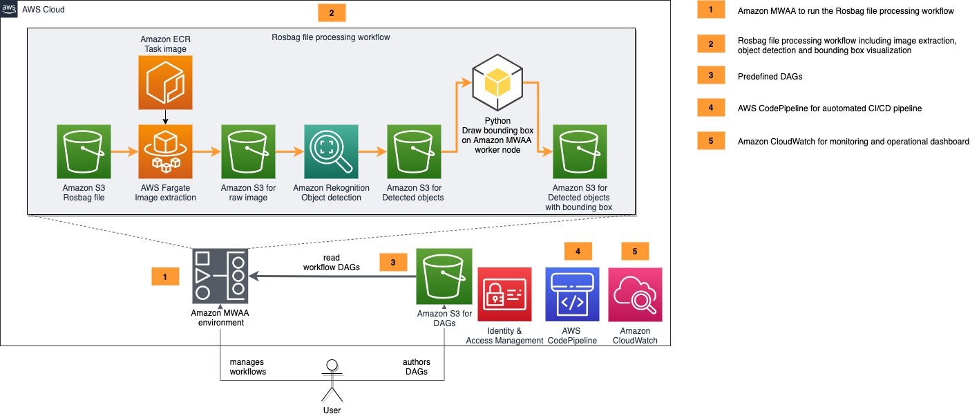
The following diagram shows a high-level overview of this solution.
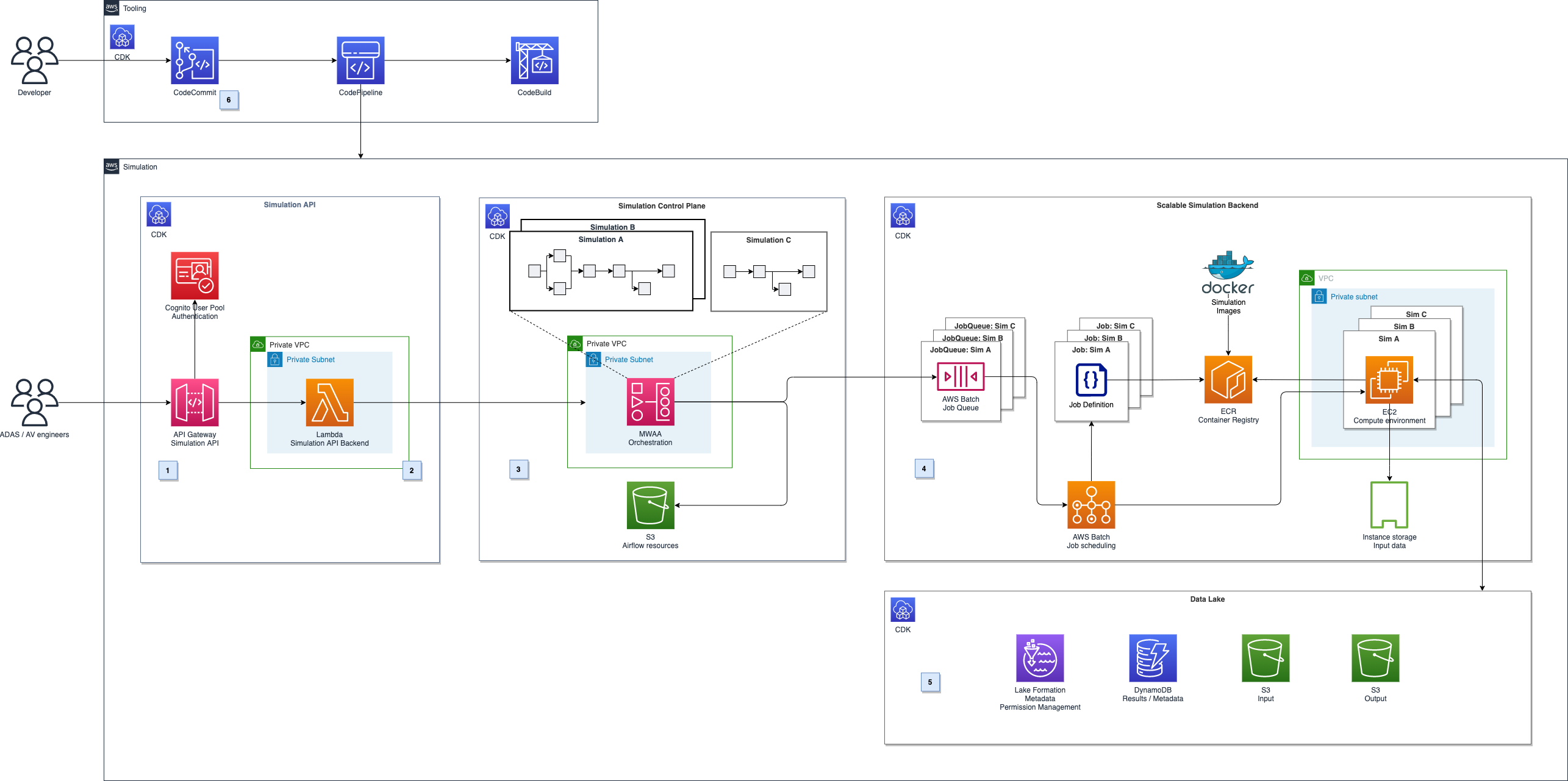
Figure 1. Architecture diagram for autonomous driving simulation
It can be broken down into five major parts, illustrated in Figure 1.
- Simulation API: Amazon API Gateway (label 1) provides a REST API for authenticated users to schedule or monitor simulation. It runs on Amazon Managed Workflows for Apache Airflow (MWAA) using AWS Lambda (label 2).
- Simulation control plane: The simulation control plane (label 3) built on MWAA enables users to design and initiate workflows and integrate with AWS services.
- Scalable compute backend: We leverage the parallelization and elastic scalability capabilities of AWS Batch to distribute the workload (label 4). Additionally, we want to be able to run proprietary software components as part of the simulation workflows and use highly customizable Amazon EC2 compute environments. For example, we can use GPU acceleration or Graviton-based instances for workloads that must run on ARM, instead of x86 architectures.
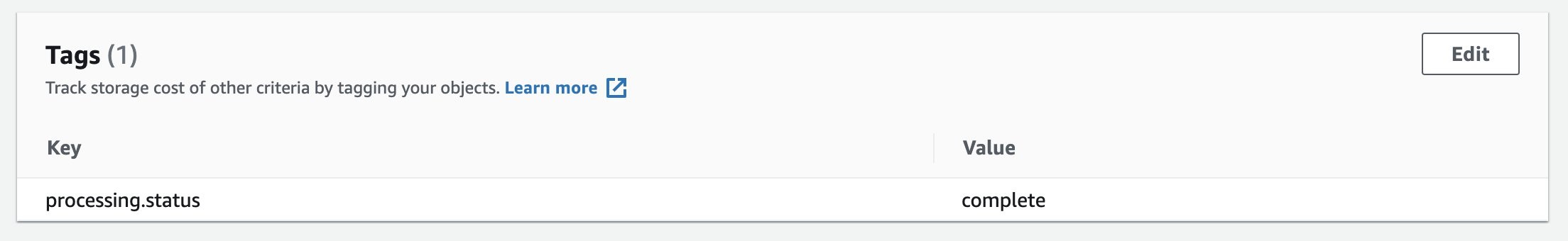
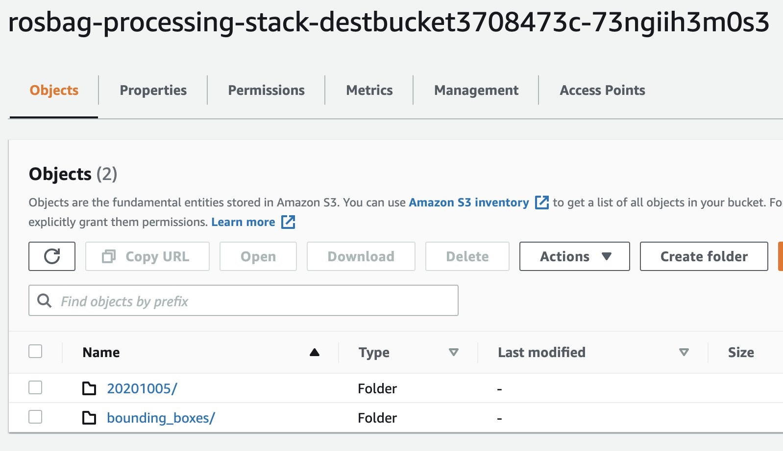
- Autonomous Driving Data Lake (ADDL) integration: The simulations’ input and output data will be stored in a data lake (label 5) on Amazon S3. To provide efficient read and write access, data gets copied before each simulation run using RAID0 bundled ephemeral instance storage drives. After the simulation, results are written back to the data lake and are ready for reporting and analytics. We use AWS Lake Formation for metadata storage, data cataloging, and permission handling.
- Automated deployment: The solution architecture’s deployment is fully automated using a CI/CD pipeline in AWS CodePipeline and AWS CodeBuild (label 6). We can then perform automated testing and deployment to multiple target environments.
In this blog we will focus on the simulation control plane, scalable compute backend, and ADDL integration.
Simulation control plane
In a typical simulation, there are tasks like data movement (copying input data and persisting the results). These steps can require high levels of parallelization or GPU support. In addition, they can involve third-party or proprietary software, specialized runtime environments, or architectures like ARM. To facilitate all task requirements, we will delegate task initiation to the AWS services that best match the requirements. Correct sequence of tasks is achieved by an orchestration layer. Decoupling the simulation orchestration from task initiation follows the key design pattern to separate concerns. This enables the architecture to be adapted to specific requirements.
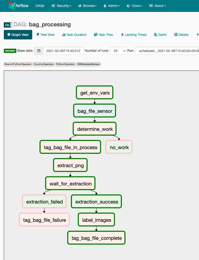
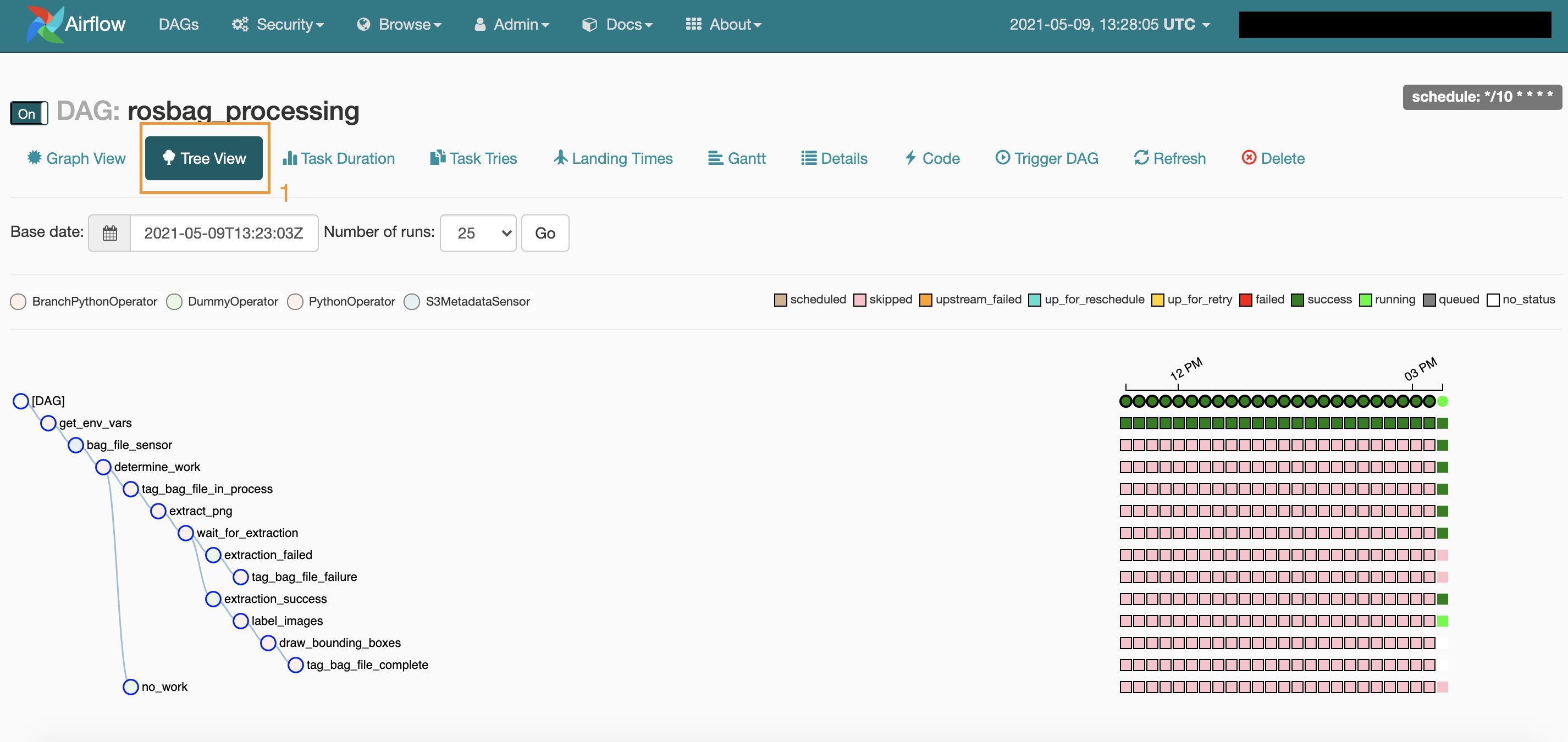
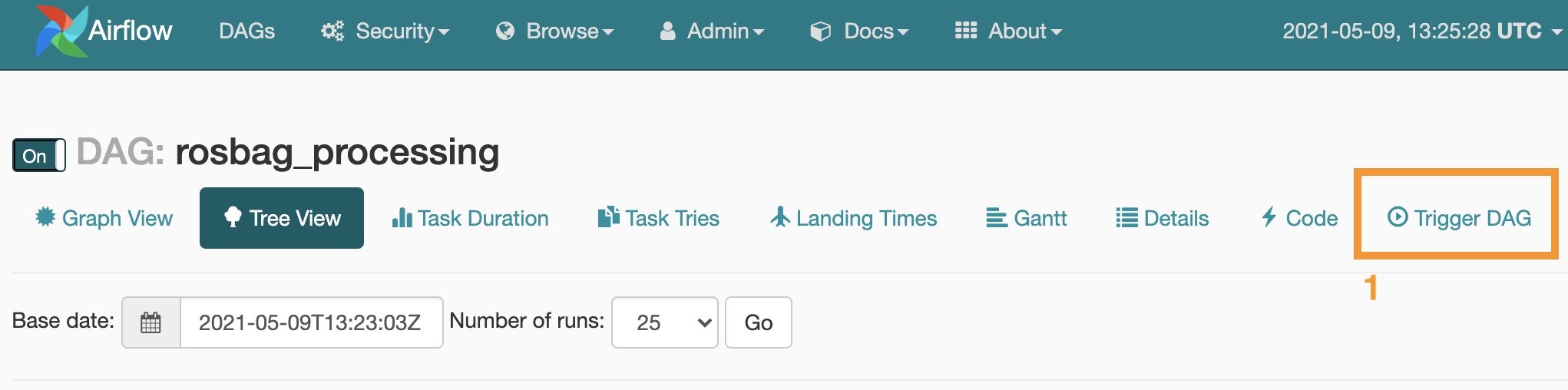
For the high-level task orchestration, we’ll introduce a simulation control plane built on MWAA. Modeling all simulation tasks in a directed acyclic graph (DAG), MWAA performs scheduling and task initiation in the correct sequence. It also handles the integration with AWS’ services. You can intuitively monitor and debug the progress of a simulation run across different services and networks. For the workflow within CAEdge, we’ll use AWS Batch to run simulations that are packaged as Docker containers.
Parameterizable workflows: Airflow supports parameterization of DAGs by providing a JSON object when triggering a DAG run that can be accessed at runtime. This enables us to create a simulation execution framework in which we model the simulation steps. It lets you specify the simulations’ parameters such as which Docker container to execute, runtime configuration, or input and output data locations, see Figures 2 and 3.
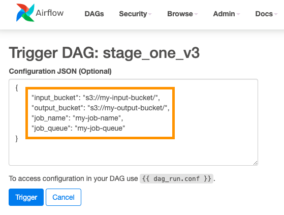
Figure 2. Specify simulations’ parameters in JSON
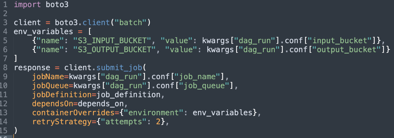
Figure 3. Read simulations’ parameters from JSON
Scalable compute backend
Publishing the Docker image: To run a simulation, you must provide a Docker container in Amazon Elastic Container Registry (ECR). Manually push Docker images to ECR using the command line interface (CLI) or using CI/CD pipeline automation.
Choosing the compute option: Containers at AWS describes the services options for developers. Various factors can contribute to your decision-making. For the CAEdge platform, we want to run thousands of containers with fine-grained control over the underlying compute instance’s configuration. We also want to run containers in privileged mode, so AWS Batch on EC2 is a great match. Figure 4 outlines the compute backend’s architecture.
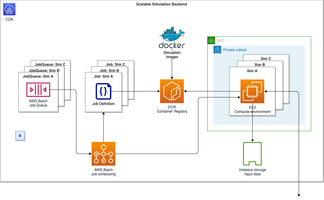
Figure 4. Compute backend architecture diagram
To run a Docker container on AWS Batch, we need three components: A job definition, a compute environment, and a job queue. The AWS Batch job definition specifies which job to run and how to run it. For example, we can define the Docker image to use, and specify the vCPU and memory configuration. The job definition will be submitted to a job queue, which in turn is linked to one or more compute environments. The compute environment specifies the compute configuration used to run a containerized workload, in addition to instance types and storage configurations. Creating a compute environment describes this more in detail. In the section ‘ADDL integration,’ we’ll describe how to select and configure the EC2 container instances to maximize network and disk I/O.
The AWS Batch array job feature can spin up thousands of independent, but similarly configured jobs. Instead of submitting a single job for each input file from the simulation control plane, we can instead submit a single array job. This provides the collection of input files as input. AWS Batch can spin up child jobs to process each entry of the collection in parallel, reducing operational overhead drastically.
With these components, we can now submit a job definition to a job queue from the simulation control plane, which will initiate on the corresponding compute environment.
ADDL integration
In the CAEdge platform, all simulation recordings and their metadata are stored and cataloged in the data lake. On average, single recordings are around 100 GB in size with simulation requests containing 100–300 recordings. A simulation request can therefore require 10–30 TB of data movement from S3 to the containers before the simulation starts. The containers’ performance will directly depend on I/O performance, as the input data is read and processed during execution. To provide the highest performance of data transfer and simulation workload, we need data storage options that maximize network and disk I/O throughput.
Choosing the storage option: For CAEdge’s simulation workloads, the storage solution acts as a temporary scratch space for the simulation containers’ input data. It should maximize I/O throughput. These requirements are met in the most cost-efficient way by choosing EC2 instances of the M5d family and their attached instance storage.
The M5d are general-purpose instances with NVMe-based SSDs, which are physically connected to the host server and provide block-level storage coupled to the lifetime of the instance. As described in the previous section, we configured AWS Batch to create compute environments using EC2’s M5d instances. While other storage options like Amazon Elastic File System (EFS) and Amazon Elastic Block Storage (EBS) can scale to match even demanding throughput scenarios, the simulation benefits from a high-performance, temporary storage location that is directly attached to the host.
Bundling the volumes: M5d instances can have multiple NVMe drives attached, depending on their size and storage configuration. To provide a single stable storage location for the simulation containers, bundle all attached NVMe SSDs into a single RAID0 volume during the instance’s launch, using a modified user data script. With this, we can provide a fixed storage location that can be accessed from the simulation containers. Additionally, we are distributing I/O operations evenly across all disks in the RAID0 configuration, which improves the read and write performance.
KPIs used for measurement
The SIL factor tells you how long the simulation takes compared to the duration of the recorded data.
SIL factor example:
- For a recording with 60 minutes of data and a simulation duration of 120 minutes, the resulting SIL factor is 120 / 60 = 2. The simulation runs twice as long as real time.
- For a recording with 60 minutes of data and a simulation duration of 60 minutes, the resulting SIL factor is 60 / 60 = 1. The simulation runs in real time.
Similarly, the aggregated SIL factor tells you how long the simulation for multiple recordings takes compared to the duration of the recorded data. It also factors in the horizontal scaling capabilities.
Aggregated SIL factor example:
- For 3 recordings with 60 minutes of data and an overall simulation duration of 120 minutes, the resulting SIL factor is 120 / 3 * 60 = 0.67. The overall simulation is a third faster than real time.
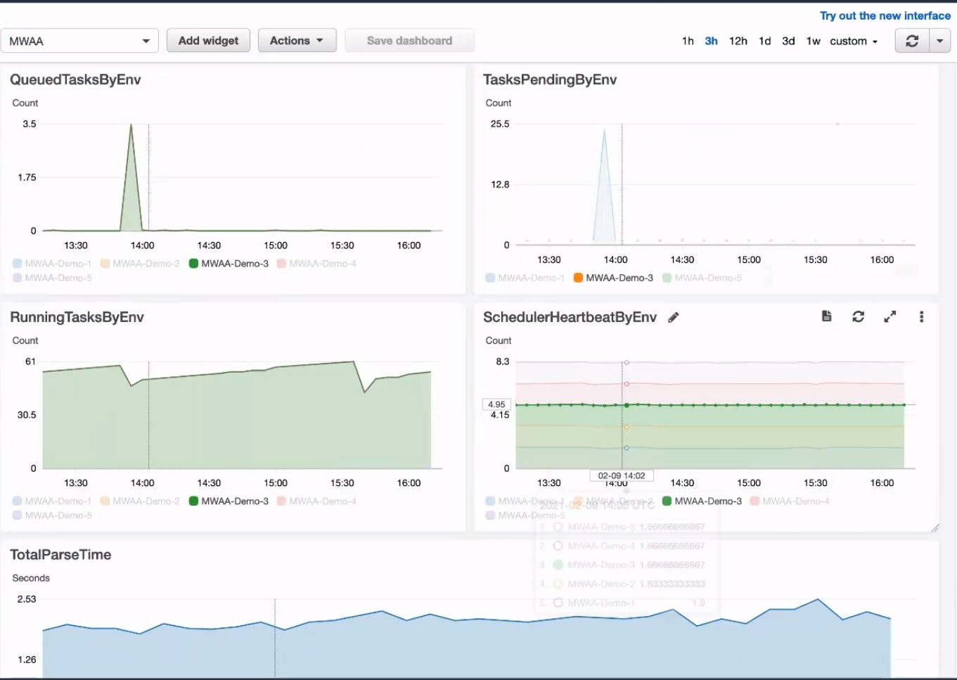
Performance results
The storage optimizations described in the ADDL integration KPI section preceding, led to an improvement of the overall simulation duration of 50%. To benchmark the overall simulation platform’s performance, we created a simulation run with 15 recordings. The simulation run completed successfully with an aggregated SIL factor of 0.363, or, alternatively put, the simulation was roughly three times faster than real time. During production use, the platform will handle simulation runs with an average of 100-300 recordings. For these runs, the aggregated SIL factor is expected to be even smaller, as more simulations can be processed in parallel.
Conclusion
In this post, we showed how to design a platform for ADAS simulation workloads using the Bring Your Own Software-In-the-Loop (BYO-SIL) concept. We covered the key components including simulation control plane, scalable compute backend, and ADDL integration based on Continental Automotive Edge (CAEdge). We discussed the key performance benefits due to horizontal scalability and how to choose an optimized storage integration pattern. This led to an improvement of the overall simulation duration of 50%.