All posts by James Beswick

Building Salesforce integrations with Amazon EventBridge and Amazon AppFlow

Post Syndicated from James Beswick original https://aws.amazon.com/blogs/compute/building-salesforce-integrations-with-amazon-eventbridge/

This post is courtesy of Den Delimarsky, Senior Product Manager, and Vinay Kondapi, Senior Product Manager.

The integration between Amazon EventBridge and Amazon AppFlow enables customers to receive and react to events from Salesforce in their event-driven applications. In this blog post, I show you how to set up the integration, and route Salesforce events to an AWS Lambda function for processing.

Amazon AppFlow is a fully managed integration service that enables you to securely transfer data between software as a service (SaaS) applications like Salesforce, Marketo, Slack, and ServiceNow, and AWS services like Amazon S3 and Amazon Redshift.

EventBridge SaaS integrations make it easier for customers to receive events from over 30 different SaaS providers. Salesforce is a popular SaaS provider among AWS customers, so it has been one of the most anticipated event sources for EventBridge. Customers want to build rich applications that can react to events that track campaigns, contracts, opportunities, and order changes.

The ability to receive these events allows you to build workflows where you can start a variety of processes. For example, you could notify a broad range of subscribers about the changes, or enrich the data with information from another service. Or you could route the event to an order delivery system.

Previously, to connect Salesforce to your application, you must write custom API polling code that routes events either directly to an application or to an event bus. With the Salesforce integration with EventBridge and Amazon AppFlow, the integration is built in minutes directly through the AWS Management Console, with no code required.

The solution outlined in this blog post is structured as follows:

Architecture overview

Setting up the event source

To set up the event source:

  1. Open the Amazon AppFlow console, and create a new flow. Choose Create flow button on the service landing page. Give your flow a unique name, and choose Next.Specify flow details
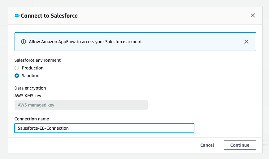
  2. In the Source name list, select Salesforce, and then choose Connect. Select the Salesforce environment you are using, and provide a unique connection name.Connect to Salesforce
  3. Choose Continue. When prompted, provide your Salesforce credentials. These are the credentials that are associated with the specific Salesforce environment selected in the previous step.
  4. Select Salesforce events from the list of available options for the flow, and choose the event that you want to route to EventBridge. This ensures that Amazon AppFlow can route specific events that are coming from Salesforce to an EventBridge event bus.Source details
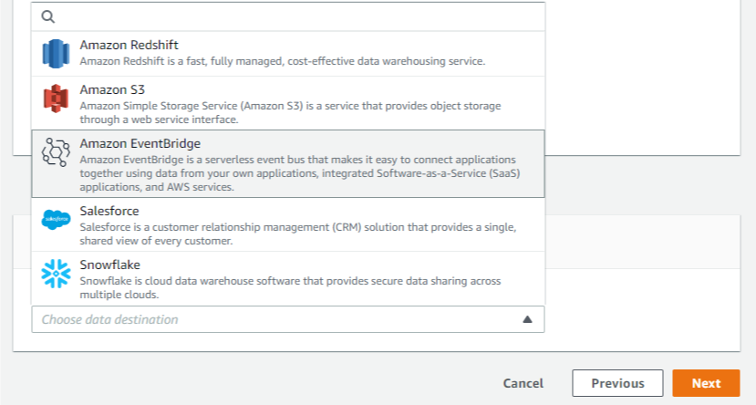
  5. With the source set up, you can now specify the destination. In the Destination name list, select EventBridge.Destination name

To send Salesforce events to EventBridge, Amazon AppFlow creates a new partner event source that is associated with a partner event bus.

To create a partner event source:

  1. Select an existing partner event source, or create a new one by choosing the list of partner event sources.Destination details
  2. When creating a new event source, you can optionally customize the name, to make it easier for you to identify it later.Generate partner event source
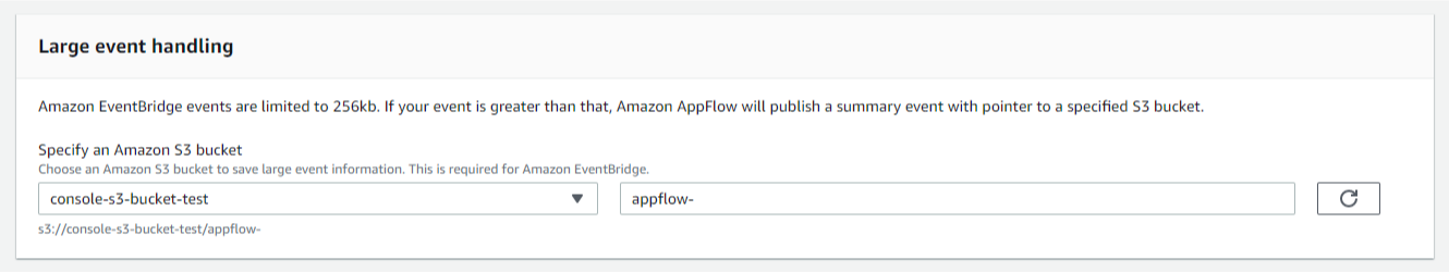
  3. Choose an Amazon S3 bucket for large events. For events that are larger than 256 KB, Amazon AppFlow sends a URL for the S3 object to the event bus instead of the event payload.Large event handling
  4. Define a flow trigger, which determines when the flow is started. Because we are tracking events, we want to react to those as they come in. Using the default Run flow on event enables this scenario as changes occur in Salesforce.Flow trigger

With Amazon AppFlow, you can also configure data field mapping, validation rules, and filters. These enable you to enrich and modify event data before it is sent to the event bus.

Once you create the flow, you must activate the event source that you created. To complete this step:

  1. Open the EventBridge console.
  2. Associate a partner event source with an event bus by following the link in the Amazon AppFlow integration dialog box, or navigating directly to the partner event sources view. You can see a partner event source with a Pending state.Partner event source
  3. Select the event source and choose Associate with event bus.
  4. Confirm the settings and choose on Associate.Associate with an event bus
  5. Return to the Amazon AppFlow console, and open the flow you were creating. Choose Activate flow.Activate flow

Your integration is now complete, and EventBridge can start receiving Salesforce events from the configured flow.

Routing Salesforce events to Lambda function

The associated partner event bus receives all events of the configured type from the connected Salesforce accounts. Now your application can react to these events with the help of rules in EventBridge. Rules allow you to set conditions for event routing that determine what targets receive event payloads. You can learn more about this functionality in the EventBridge documentation.

To create a new rule:

  1. Go to the rules view in the EventBridge console, and choose Create rule.EventBridge Rules
  2. Provide a unique name and an optional description for your rule.
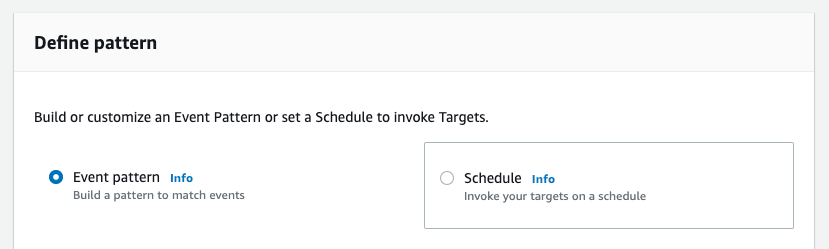
  3. Select the Event pattern option in the Define pattern section. With event pattern configuration, you can define parts of the event payload that EventBridge must look at to determine where to route the event.Define pattern
    For this exercise, start by capturing every Salesforce event that goes through the partner event bus. The only events routed through this bus are from the partner event source. In this case, it is Amazon AppFlow connected to Salesforce.
  4. Set the event matching pattern to Pre-defined pattern by service, with the service provider being All Events. The default setting allows you to receive all events that are coming through the partner event bus.Event matching pattern
  5. Select the event bus that the rule should be associated with. Choose Custom or partner event bus and select the event bus that you associated with the Amazon AppFlow event source. Every rule in EventBridge is associated with an event bus.Select event bus

When rules are triggered, the event can be routed to other AWS services. Additionally, every rule can have up to five different AWS targets. You can read more about available targets in the EventBridge documentation. For this blog post, we use an AWS Lambda function as a target for Salesforce events received from Amazon AppFlow.

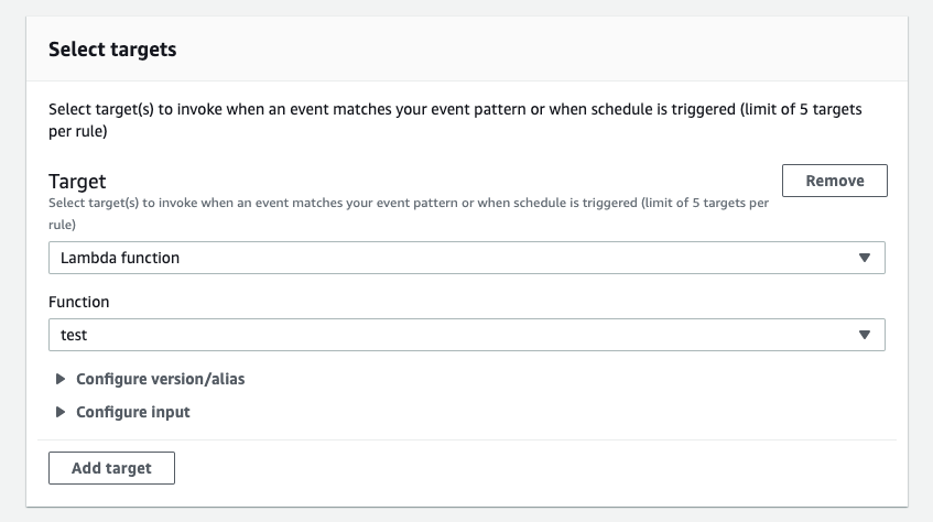
To configure targets for your rule:

  1. From the list of targets, select Lambda function, and select an existing function. If you do not yet have a function available, you can create one in the AWS Lambda console.Select targets
  2. Choose Create. You have now completed the rule setup.

Now, Salesforce events that match the configured type are routed directly to a Lambda function in your account.

Testing the integration

To test the integration:

  1. Open the Lambda view in the AWS Management Console.
  2. Choose the function that is handling the events from EventBridge.
  3. In the Function code section, update the code to:
    exports.handler = async (event) => {
        console.log(event);
        const response = {
            statusCode: 200,
            body: JSON.stringify('Hello from Lambda!'),
        };
        return response;
    };
    

    Function code

  4. Choose Save.
  5. Open your Salesforce instance, and take an action that is associated with the event you configured earlier. For example, you could update a contract or create an order.
  6. Go back to your function in AWS Management Console, and choose the Monitoring tab.Lambda function monitoring tab
  7. Scroll to CloudWatch Logs Insights section.CloudWatch Logs Insights
  8. Choose the latest log stream. Make sure that the timestamp approximately matches the time when you triggered the action in Salesforce.
  9. Choose the log stream.
  10. Observe log events that contain Salesforce event data.

You have completed your first Salesforce integration with EventBridge and Amazon AppFlow. You are now able to build decoupled and highly scalable applications that integrate with Salesforce.

Conclusion

Building decoupled and scalable cross-service applications is more relevant than ever with requirements for high availability, consistency, and reliability. This blog post demonstrates a solution that connects Salesforce to an event-driven application that uses EventBridge and Amazon AppFlow to route events. The application uses events from Salesforce as a starting point for a custom processing workflow in a Lambda function.

To learn more about EventBridge, visit the EventBridge documentation or EventBridge Learning Path.

To learn more about Amazon AppFlow, visit the Amazon AppFlow documentation.

Using serverless backends to iterate quickly on web apps – part 2

Post Syndicated from James Beswick original https://aws.amazon.com/blogs/compute/using-serverless-backends-to-iterate-quickly-on-web-apps-part-2/

This series is about building flexible solutions that can adapt as user requirements change. One of the challenges of building modern web applications is that requirements can change quickly. This is especially true for new applications that are finding their product-market fit. Many development teams start building a product with one set of requirements, and quickly find they must build a product with different features.

For both start-ups and enterprises, it’s often important to find a development methodology and architecture that allows flexibility. This is the surest way to keep up with feature requests in evolving products and innovate to delight your end-users. In this post, I show how to build sophisticated workflows using minimal custom code.

Part 1 introduces the Happy Path application that allows park visitors to share maps and photos with other users. In that post, I explain the functionality, how to deploy the application, and walk through the backend architecture.

The Happy Path application accepts photo uploads from users’ smartphones. The application architecture must support 100,000 monthly active users. These binary uploads are typically 3–9 MB in size and must be resized and optimized for efficient distribution.

Using a serverless approach, you can develop a robust low-code solution that can scale to handle millions of images. Additionally, the solution shown here is designed to handle complex changes that are introduced in subsequent versions of the software. The code and instructions for this application are available in the GitHub repo.

Architecture overview

After installing the backend in the previous post, the architecture looks like this:

In this design, the API, storage, and notification layers exist as one application, and the business logic layer is a separate application. These two applications are deployed using AWS Serverless Application Model (AWS SAM) templates. This architecture uses Amazon EventBridge to pass events between the two applications.

In the business logic layer:

  1. The workflow starts when events are received from EventBridge. Each time a new object is uploaded by an end-user, the PUT event in the Amazon S3 Upload bucket triggers this process.
  2. After the workflow is completed successfully, processed images are stored in the Distribution bucket. Related metadata for the object is also stored in the application’s Amazon DynamoDB table.

By separating the architecture into two independent applications, you can replace the business logic layer as needed. Providing that the workflow accepts incoming events and then stores processed images in the S3 bucket and DynamoDB table, the workflow logic becomes interchangeable. Using the pattern, this workflow can be upgraded to handle new functionality.

Introducing AWS Step Functions for workflow management

One of the challenges in building distributed applications is coordinating components. These systems are composed of separate services, which makes orchestrating workflows more difficult than working with a single monolithic application. As business logic grows more complex, if you attempt to manage this in custom code, it can become quickly convoluted. This is especially true if it handles retries and error handling logic, and it can be hard to test and maintain.

AWS Step Functions is designed to coordinate and manage these workflows in distributed serverless applications. To do this, you create state machine diagrams using Amazon States Language (ASL). Step Functions renders a visualization of your state machine, which makes it simpler to see the flow of data from one service to another.

Each state machine consists of a series of steps. Each step takes an input and produces an output. Using ASL, you define how this data progresses through the state machine. The flow from step to step is called a transition. All state machines transition from a Start state towards an End state.

The Step Functions service manages the state of individual executions. The service also supports versioning, which makes it easier to modify state machines in production systems. Executions continue to use the version of a state machine when they were started, so it’s possible to have active executions on multiple versions.

For developers using VS Code, the AWS Toolkit extension provides support for writing state machines using ASL. It also renders visualizations of those workflows. Combined with AWS Serverless Application Model (AWS SAM) templates, this provides a powerful way to deploy and maintain applications based on Step Functions. I refer to this IDE and AWS SAM in this walkthrough.

Version 1: Image resizing

The Happy Path application uses Step Functions to manage the image-processing part of the backend. The first version of this workflow resizes the uploaded image.

To see this workflow:

  1. In VS Code, open the workflows/statemachines folder in the Explorer panel.
  2. Choose the v1.asl.sjon file.v1 state machine
  3. Choose the Render graph option in the CodeLens. This opens the workflow visualization.CodeLens - Render graph

In this basic workflow, the state machine starts at the Resizer step, then progresses to the Publish step before ending:

  • In the top-level attributes in the definition, StartsAt sets the Resizer step as the first action.
  • The Resizer step is defined as a task with an ARN of a Lambda function. The Next attribute determines that the Publish step is next.
  • In the Publish step, this task defines a Lambda function using an ARN reference. It sets the input payload as the entire JSON payload. This step is set as the End of the workflow.

Deploying the Step Functions workflow

To deploy the state machine:

  1. In the terminal window, change directory to the workflows/templates/v1 folder in the repo.
  2. Execute these commands to build and deploy the AWS SAM template:
    sam build
    sam deploy –guided
  3. The deploy process prompts you for several parameters. Enter happy-path-workflow-v1 as the Stack Name. The other values are the outputs from the backend deployment process, detailed in the repo’s README. Enter these to complete the deployment.
  4. SAM deployment output

Testing and inspecting the deployed workflow

Now the workflow is deployed, you perform an integration test directly from the frontend application.

To test the deployed v1 workflow:

  1. Open the frontend application at https://localhost:8080 in your browser.
  2. Select a park location, choose Show Details, and then choose Upload images.
  3. Select an image from the sample photo dataset.
  4. After a few seconds, you see a pop-up message confirming that the image has been added:Upload confirmation message
  5. Select the same park location again, and the information window now shows the uploaded image:Happy Path - park with image data

To see how the workflow processed this image:

  1. Navigate to the Steps Functions console.
  2. Here you see the v1StateMachine with one execution in the Succeeded column.Successful execution view
  3. Choose the state machine to display more information about the start and end time.State machine detail
  4. Select the execution ID in the Executions panel to open details of this single instance of the workflow.

This view shows important information that’s useful for understanding and debugging an execution. Under Input, you see the event passed into Step Functions by EventBridge:

Event detail from EventBridge

This contains detail about the S3 object event, such as the bucket name and key, together with the placeId, which identifies the location on the map. Under Output, you see the final result from the state machine, shows a successful StatusCode (200) and other metadata:

Event output from the state machine

Using AWS SAM to define and deploy Step Functions state machines

The AWS SAM template defines both the state machine, the trigger for executions, and the permissions needed for Step Functions to execute. The AWS SAM resource for a Step Functions definition is AWS::Serverless::StateMachine.

Definition permissions in state machines

In this example:

  • DefinitionUri refers to an external ASL definition, instead of embedding the JSON in the AWS SAM template directly.
  • DefinitionSubstitutions allow you to use tokens in the ASL definition that refer to resources created in the AWS SAM template. For example, the token ${ResizerFunctionArn} refers to the ARN of the resizer Lambda function.
  • Events define how the state machine is invoked. Here it defines an EventBridge rule. If an event matches this source and detail-type, it triggers an execution.
  • Policies: the Step Functions service must have permission to invoke the services that perform tasks in the state machine. AWS SAM policy templates provide a convenient shorthand for common execution policies, such as invoking a Lambda function.

This workflow application is separate from the main backend template. As more functionality is added to the workflow, you deploy the subsequent AWS SAM templates in the same way.

Conclusion

Using AWS SAM, you can specify serverless resources, configure permissions, and define substitutions for the ASL template. You can deploy a standalone Step Functions-based application using the AWS SAM CLI, separately from other parts of your application. This makes it easier to decouple and maintain larger applications. You can visualize these workflows directly in the VS Code IDE in addition to the AWS Management Console.

In part 3, I show how to build progressively more complex workflows and how to deploy these in-place without affecting the other parts of the application.

To learn more about building serverless web applications, see the Ask Around Me series.