Post Syndicated from Saurabh Bhutyani original https://aws.amazon.com/blogs/big-data/use-aws-data-exchange-to-seamlessly-share-apache-hudi-datasets/
Apache Hudi was originally developed by Uber in 2016 to bring to life a transactional data lake that could quickly and reliably absorb updates to support the massive growth of the company’s ride-sharing platform. Apache Hudi is now widely used to build very large-scale data lakes by many across the industry. Today, Hudi is the most active and high-performing open source data lakehouse project, known for fast incremental updates and a robust services layer.
Apache Hudi serves as an important data management tool because it allows you to bring full online transaction processing (OLTP) database functionality to data stored in your data lake. As a result, Hudi users can store massive amounts of data with the data scaling costs of a cloud object store, rather than the more expensive scaling costs of a data warehouse or database. It also provides data lineage, integration with leading access control and governance mechanisms, and incremental ingestion of data for near real-time performance. AWS, along with its partners in the open source community, has embraced Apache Hudi in several services, offering Hudi compatibility in Amazon EMR, Amazon Athena, Amazon Redshift, and more.
AWS Data Exchange is a service provided by AWS that enables you to find, subscribe to, and use third-party datasets in the AWS Cloud. A dataset in AWS Data Exchange is a collection of data that can be changed or updated over time. It also provides a platform through which a data producer can make their data available for consumption for subscribers.
In this post, we show how you can take advantage of the data sharing capabilities in AWS Data Exchange on top of Apache Hudi.
Benefits of AWS Data Exchange
AWS Data Exchange offers a series of benefits to both parties. For subscribers, it provides a convenient way to access and use third-party data without the need to build and maintain data delivery, entitlement, or billing technology. Subscribers can find and subscribe to thousands of products from qualified AWS Data Exchange providers and use them with AWS services. For providers, AWS Data Exchange offers a secure, transparent, and reliable channel to reach AWS customers. It eliminates the need to build and maintain data delivery, entitlement, and billing technology, allowing providers to focus on creating and managing their datasets.
To become a provider on AWS Data Exchange, there are a few steps to determine eligibility. Providers need to register to be a provider, make sure their data meets the legal eligibility requirements, and create datasets, revisions, and import assets. Providers can define public offers for their data products, including prices, durations, data subscription agreements, refund policies, and custom offers. The AWS Data Exchange API and AWS Data Exchange console can be used for managing datasets and assets.
Overall, AWS Data Exchange simplifies the process of data sharing in the AWS Cloud by providing a platform for customers to find and subscribe to third-party data, and for providers to publish and manage their data products. It offers benefits for both subscribers and providers by eliminating the need for complex data delivery and entitlement technology and providing a secure and reliable channel for data exchange.
Solution overview
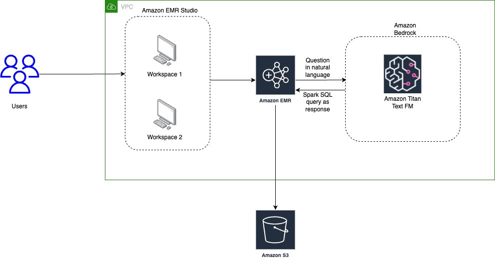
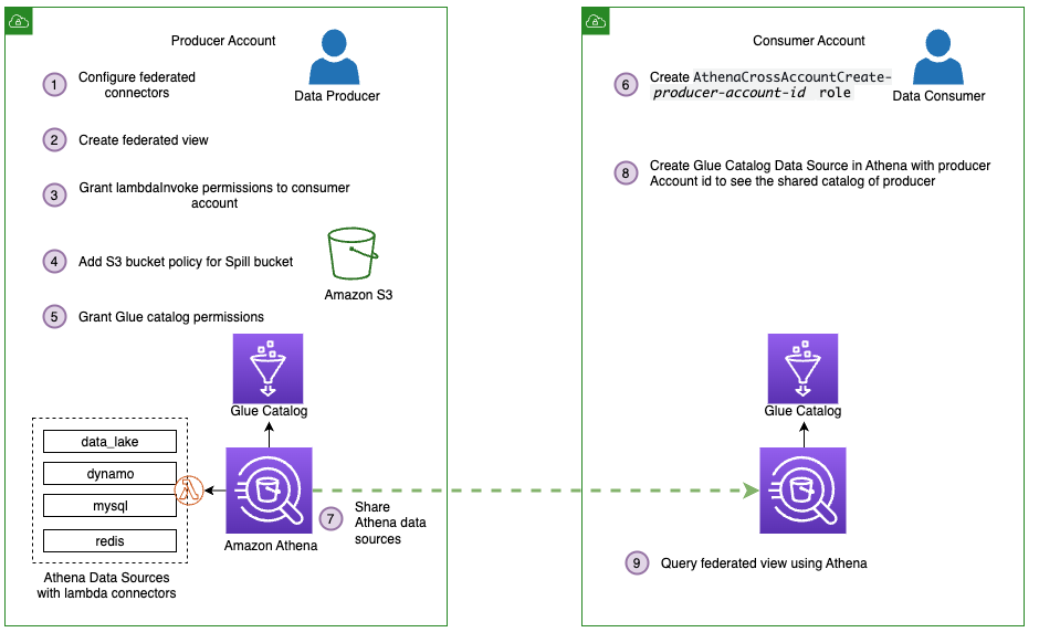
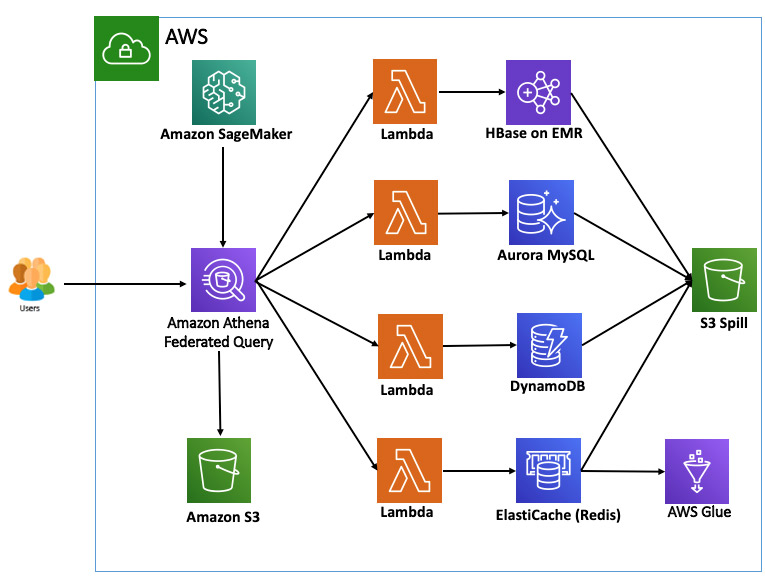
Combining the scale and operational capabilities of Apache Hudi with the secure data sharing features of AWS Data Exchange enables you to maintain a single source of truth for your transactional data. Simultaneously, it enables automatic business value generation by allowing other stakeholders to use the insights that the data can provide. This post shows how to set up such a system in your AWS environment using Amazon Simple Storage Service (Amazon S3), Amazon EMR, Amazon Athena, and AWS Data Exchange. The following diagram illustrates the solution architecture.

Set up your environment for data sharing
You need to register as a data producer before you create datasets and list them in AWS Data Exchange as data products. Complete the following steps to register as a data provider:
- Sign in to the AWS account that you want to use to list and manage products on AWS Data Exchange.
As a provider, you are responsible for complying with these guidelines and the Terms and Conditions for AWS Marketplace Sellers and the AWS Customer Agreement. AWS may update these guidelines. AWS removes any product that breaches these guidelines and may suspend the provider from future use of the service. AWS Data Exchange may have some AWS Regional requirements; refer to Service endpoints for more information. - Open the AWS Marketplace Management Portal registration page and enter the relevant information about how you will use AWS Data Exchange.
- For Legal business name, enter the name that your customers see when subscribing to your data.
- Review the terms and conditions and select I have read and agree to the AWS Marketplace Seller Terms and Conditions.

- Select the information related to the types of products you will be creating as a data provider.
- Choose Register & Sign into Management Portal.


If you want to submit paid products to AWS Marketplace or AWS Data Exchange, you must provide your tax and banking information. You can add this information on the Settings page:
- Choose the Payment information tab.
- Choose Complete tax information and complete the form.
- Choose Complete banking information and complete the form.
- Choose the Public profile tab and update your public profile.
- Choose the Notifications tab and configure an additional email address to receive notifications.
You’re now ready to configure seamless data sharing with AWS Data Exchange.
Upload Apache Hudi datasets to AWS Data Exchange
After you create your Hudi datasets and register as a data provider, complete the following steps to create the datasets in AWS Data Exchange:
- Sign in to the AWS account that you want to use to list and manage products on AWS Data Exchange.
- On the AWS Data Exchange console, choose Owned data sets in the navigation pane.
- Choose Create data set.

- Select the dataset type you want to create (for this post, we select Amazon S3 data access).

- Choose Choose Amazon S3 locations.

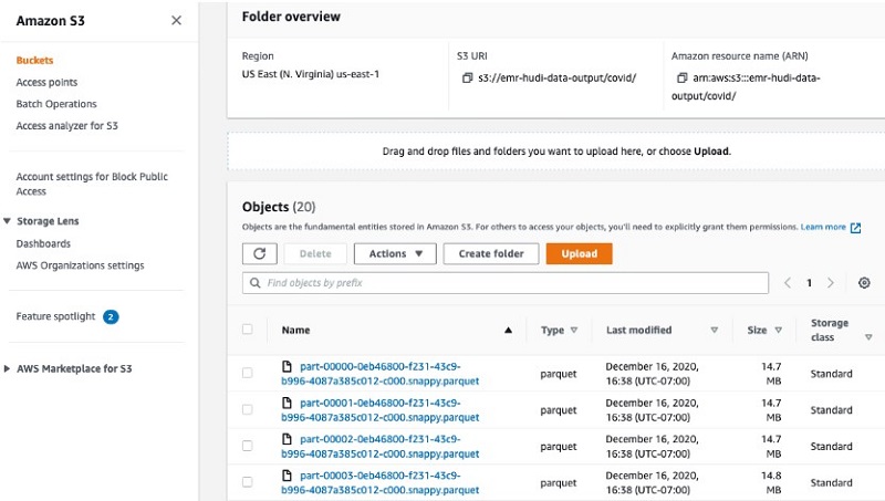
- Choose the Amazon S3 location where you have your Hudi datasets.


After you add the Amazon S3 location to register in AWS Data Exchange, a bucket policy is generated.
- Copy the JSON file and update the bucket policy in Amazon S3.

- After you update the bucket policy, choose Next.
- Wait for the
CREATE_S3_DATA_ACCESS_FROM_S3_BUCKETjob to show as Completed, then choose Finalize data set.


Publish a product using the registered Hudi dataset
Complete the following steps to publish a product using the Hudi dataset:
- On the AWS Data Exchange console, choose Products in the navigation pane.
Make sure you’re in the Region where you want to create the product. - Choose Publish new product to start the workflow to create a new product.
- Choose which product visibility you want to have: public (it will be publicly available in AWS Data Exchange catalog as well as the AWS Marketplace websites) or private (only the AWS accounts you share with will have access to it).
- Select the sensitive information category of the data you are publishing.
- Choose Next.
- Select the dataset that you want to add to the product, then choose Add selected to add the dataset to the new product.
- Define access to your dataset revisions based on time. For more information, see Revision access rules.
- Choose Next.
- Provide the information for a new product, including a short description.
One of the required fields is the product logo, which must be in a supported image format (PNG, JPG, or JPEG) and the file size must be 100 KB or less.

- Optionally, in the Define product section, under Data dictionaries and samples, select a dataset and choose Edit to upload a data dictionary to the product.
- For Long description, enter the description to display to your customers when they look at your product. Markdown formatting is supported.
- Choose Next.
- Based on your choice of product visibility, configure the offer, renewal, and data subscription agreement.
- Choose Next.
- Review all the products and offer information, then choose Publish to create the new private product.

Manage permissions and access controls for shared datasets
Datasets that are published on AWS Data Exchange can only be used when customers are subscribed to the products. Complete the following steps to subscribe to the data:
- On the AWS Data Exchange console, choose Browse catalog in the navigation pane.
- In the search bar, enter the name of the product you want to subscribe to and press Enter.
- Choose the product to view its detail page.
- On the product detail page, choose Continue to Subscribe.
- Choose your preferred price and duration combination, choose whether to enable auto-renewal for the subscription, and review the offer details, including the data subscription agreement (DSA).
The dataset is available in the US East (N. Virginia) Region. - Review the pricing information, choose the pricing offer and, if you and your organization agree to the DSA, pricing, and support information, choose Subscribe.
After the subscription has gone through, you will be able to see the product on the Subscriptions page.
Create a table in Athena using an Amazon S3 access point
Complete the following steps to create a table in Athena:
- Open the Athena console.
- If this is the first time using Athena, choose Explore Query Editor and set up the S3 bucket where query results will be written:
Athena will display the results of your query on the Athena console, or send them through your ODBC/JDBC driver if that is what you are using. Additionally, the results are written to the result S3 bucket.- Choose View settings.
- Choose Manage.
- Under Query result location and encryption, choose Browse Amazon S3 to choose the location where query results will be written.
- Choose Save.
- Choose a bucket and folder you want to automatically write the query results to.
Athena will display the results of your query on the Athena console, or send them through your ODBC/JDBC driver if that is what you are using. Additionally, the results are written to the result S3 bucket.
- Complete the following steps to create a workgroup:
- In the navigation pane, choose Workgroups.
- Choose Create workgroup.

- Enter a name for your workgroup (for this post,
data_exchange), select your analytics engine (Athena SQL), and select Turn on queries on requester pay buckets in Amazon S3.
This is important to access third-party datasets.

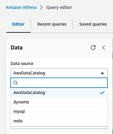
- In the Athena query editor, choose the workgroup you created.

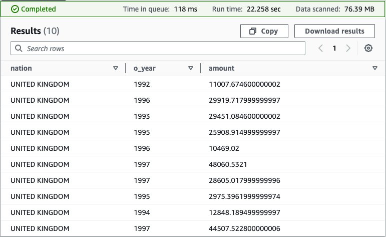
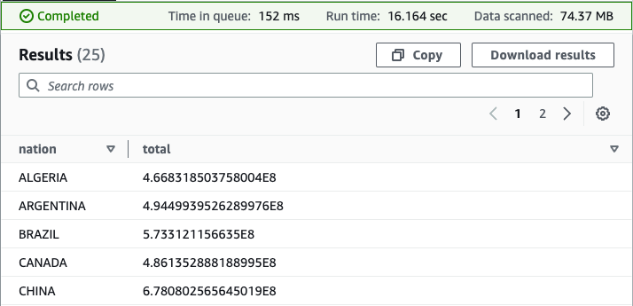
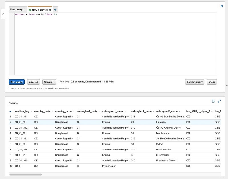
- Run the following DDL to create the table:


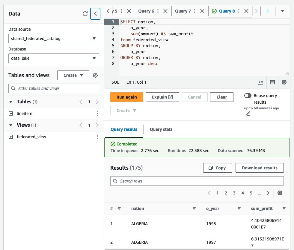
Now you can run your analytical queries using Athena SQL statements. The following screenshot shows an example of the query results.

Enhanced customer collaboration and experience with AWS Data Exchange and Apache Hudi
AWS Data Exchange provides a secure and simple interface to access high-quality data. By providing access to over 3,500 datasets, you can use leading high-quality data in your analytics and data science. Additionally, the ability to add Hudi datasets as shown in this post allows you to enable deeper integration with lakehouse use cases. There are several potential use cases where having Apache Hudi datasets integrated into AWS Data Exchange can accelerate business outcomes, such as the following:
- Near real-time updated datasets – One of Apache Hudi’s defining features is the ability to provide near real-time incremental data processing. As new data flows in, Hudi allows that data to be ingested in real time, providing a central source of up-to-date truth. AWS Data Exchange supports dynamically updated datasets, which can keep up with these incremental updates. For downstream customers that rely on the most up-to-date information for their use cases, the combination of Apache Hudi and AWS Data Exchange means that they can subscribe to a dataset in AWS Data Exchange and know that they’re getting incrementally updated data.
- Incremental pipelines and processing – Hudi supports incremental processing and updates to data in the data lake. This is especially valuable because it enables you to only update or process any data that has changed and materialized views that are valuable for your business use case.
Best practices and recommendations
We recommend the following best practices for security and compliance:
- Enable AWS Lake Formation or other data governance systems as part of creating the source data lake
- To maintain compliance, you can use the guides provided by AWS Artifact
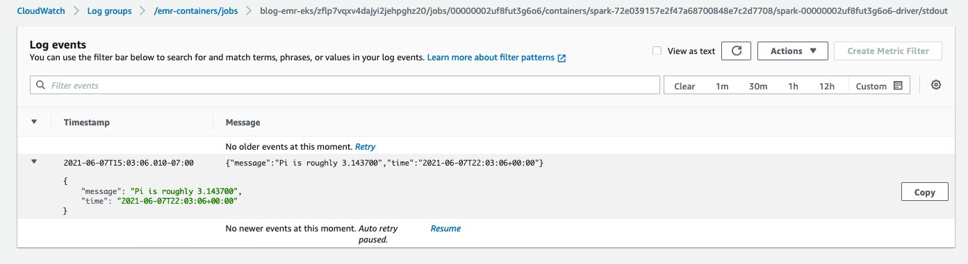
For monitoring and management, you can enable Amazon CloudWatch logs on your EMR clusters along with CloudWatch alerts to maintain pipeline health.
Conclusion
Apache Hudi enables you to bring to life massive amounts of data stored in Amazon S3 for analytics. It provides full OLAP capabilities, enables incremental processing and querying, along with maintaining the ability to run deletes to remain GDPR compliant. Combining this with the secure, reliable, and user-friendly data sharing capabilities of AWS Data Exchange means that the business value unlocked by a Hudi lakehouse doesn’t need to remain limited to the producer that generates this data.
For more use cases about using AWS Data Exchange, see Learning Resources for Using Third-Party Data in the Cloud. To learn more about creating Apache Hudi data lakes, refer to Build your Apache Hudi data lake on AWS using Amazon EMR – Part 1. You can also consider using a fully managed lakehouse product such as Onehouse.
About the Authors
 Saurabh Bhutyani is a Principal Analytics Specialist Solutions Architect at AWS. He is passionate about new technologies. He joined AWS in 2019 and works with customers to provide architectural guidance for running generative AI use cases, scalable analytics solutions and data mesh architectures using AWS services like Amazon Bedrock, Amazon SageMaker, Amazon EMR, Amazon Athena, AWS Glue, AWS Lake Formation, and Amazon DataZone.
 Ankith Ede is a Data & Machine Learning Engineer at Amazon Web Services, based in New York City. He has years of experience building Machine Learning, Artificial Intelligence, and Analytics based solutions for large enterprise clients across various industries. He is passionate about helping customers build scalable and secure cloud based solutions at the cutting edge of technology innovation.
 Chandra Krishnan is a Solutions Engineer at Onehouse, based in New York City. He works on helping Onehouse customers build business value from their data lakehouse deployments and enjoys solving exciting challenges on behalf of his customers. Prior to Onehouse, Chandra worked at AWS as a Data and ML Engineer, helping large enterprise clients build cutting edge systems to drive innovation in their organizations.


 Saurabh Bhutyani is a Principal Analytics Specialist Solutions Architect at AWS. He is passionate about new technologies. He joined AWS in 2019 and works with customers to provide architectural guidance for running generative AI use cases, scalable analytics solutions and data mesh architectures using AWS services like Amazon Bedrock, Amazon SageMaker, Amazon EMR, Amazon Athena, AWS Glue, AWS Lake Formation, and Amazon DataZone.
 Harsh Vardhan is an AWS Senior Solutions Architect, specializing in analytics. He has over 8 years of experience working in the field of big data and data science. He is passionate about helping customers adopt best practices and discover insights from their data.

 Pathik Shah is a Sr. Big Data Architect on Amazon Athena. He joined AWS in 2015 and has been focusing in the big data analytics space since then, helping customers build scalable and robust solutions using AWS analytics services.


 Saurabh Bhutyani is a Senior Big Data Specialist Solutions Architect at Amazon Web Services. He is an early adopter of open-source big data technologies. At AWS, he works with customers to provide architectural guidance for running analytics solutions on Amazon EMR, Amazon Athena, AWS Glue, and AWS Lake Formation. In his free time, he likes to watch movies and spend time with his family.


 Saurabh Bhutyani is a Senior Big Data Specialist Solutions Architect at Amazon Web Services. He is an early adopter of open-source big data technologies. At AWS, he works with customers to provide architectural guidance for running analytics solutions on Amazon EMR, Amazon Athena, AWS Glue, and AWS Lake Formation.
 Amir Basirat is a Big Data Specialist Solutions Architect at Amazon Web Services, focused on Amazon EMR, Amazon Athena, AWS Glue, and AWS Lake Formation, where he helps customers craft distributed analytics applications on the AWS platform. Prior to his AWS Cloud journey, he worked as a big data specialist for different technology companies. He also has a PhD in computer science, where his research primarily focused on large-scale distributed computing and neural networks.