Tag Archives: Amazon Application Recovery Controller (ARC)

Running multi-day AZ evacuation drills with ARC Zonal Shift

Post Syndicated from Antoine Boucherie original https://aws.amazon.com/blogs/architecture/running-multi-day-az-evacuation-drills-with-arc-zonal-shift/

Running a multi-day Availability Zone evacuation drill with ARC Zonal Shift is an effective way to prove your application can withstand a sustained impairment. Multi-Availability Zone deployment is an architectural best practice for building resilient applications on AWS, but there is a gap between deploying multi-AZ and proving it works under sustained stress. Traditional disaster recovery (DR) tests validate the failover mechanism. A typical test shifts traffic, confirms targets respond, and rolls back within minutes. These short exercises don’t surface the issues that only appear over hours or days.

A multi-day AZ evacuation forces time-dependent behaviors to play out completely, exposing failure modes that brief tests miss:

  • Auto Scaling policies that aren’t tuned for sustained N-1 operation over a full day.
  • Deployment pipelines that don’t validate AZ health before placing new workloads.
  • Stale DNS or cached database endpoints.
  • Time-based routine operational processes tested against an N-1 architecture (certificate rotations, credential and secret rotations, maintenance windows, log rotation, backup automation, and cron jobs).
  • Long-lived database connections pinned to a specific AZ that are only used infrequently.
  • Recovery after a sustained multi-day shift, which is a different operational procedure than rolling back to a warm, nearly identical AZ within minutes.

By shifting all traffic away from a single AZ for 48–72 hours using Amazon Application Recovery Controller (ARC) Zonal Shift, you force your architecture to sustain full production load on N-1 zones. This proves capacity sufficiency, database stability, and client reconnection behavior, but most importantly, that your teams can operate normally for days on N-1 capacity.

This post shows you how to plan and run a multi-day AZ evacuation drill across Amazon Elastic Container Service (Amazon ECS), Amazon Elastic Kubernetes Service (Amazon EKS), Amazon Relational Database Service (Amazon RDS) for PostgreSQL, and Amazon Aurora PostgreSQL, with step-by-step CLI commands, a prerequisites section, observability metrics, and restore procedures.

Why financial services institutions are doing this already

Financial services organizations face unique regulatory pressure to demonstrate, not just document, their disaster recovery capabilities. Across the world, there is an increasing focus on building and demonstrating operational resilience within regulated entities. This is shifting the mindset from “show us your runbook” to “show us the evidence”. This uplift in control environments is driving financial services companies to conduct live DR testing under realistic conditions and produce auditable proof of recovery within defined timeframes. Some insurers and banks are now running periodic AZ evacuation drills as part of their operational resilience programs, shifting from “we have multi-AZ” to “we have proven multi-AZ”. Using ARC Zonal Shift, you can shift traffic at the infrastructure layer without changing application code. It works natively across Application Load Balancer, Network Load Balancer, Amazon Elastic Compute Cloud (Amazon EC2) Auto Scaling groups, and Amazon EKS clusters.

Solution overview

In this walkthrough, we demonstrate how to evacuate an Availability Zone for a multi-tier digital platform running on AWS.

We deliberately include both ECS and EKS, and two database engines, to show the evacuation procedure for each major service type readers are likely to run. The architecture is illustrative only.

The following table outlines the architecture:

Layer Components Multi-AZ Configuration
Traffic ingress Application Load Balancer (ALB) fronting ECS Deployed across 3 AZs, cross-zone load balancing activated
Compute (containers) Amazon ECS (Fargate) Stateless tasks distributed across 3 AZ subnets
Traffic ingress Network Load Balancer (NLB) fronting EKS Deployed across 3 AZs, cross-zone load balancing activated
Compute (Kubernetes) Amazon EKS or EKS Auto Mode Stateless services with topology spread constraints across 3 AZs
Database Amazon RDS for PostgreSQL Multi-AZ: primary in AZ A, standby in AZ B
Database Amazon Aurora PostgreSQL Writer in AZ A, reader in AZ B. Storage replicated across all 3 AZs

Note that the Aurora storage layer differs from standard RDS Multi-AZ. Aurora synchronously replicates data to six storage nodes across Availability Zones independently of compute instances, so only the writer or reader instance needs to be failed over as the storage remains fully available throughout the drill.

In this walkthrough, we evacuate AZ A, the zone hosting the RDS primary and Aurora writer.
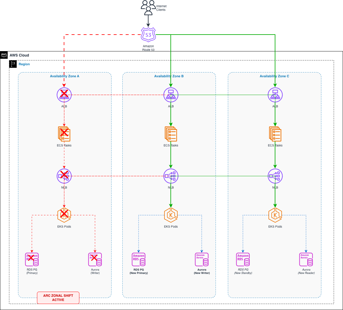
Multi-tier architecture spanning three Availability Zones: an Application Load Balancer fronting Amazon ECS and a Network Load Balancer fronting Amazon EKS, with Amazon RDS for PostgreSQL and Amazon Aurora PostgreSQL databases, before evacuating AZ A.

How ARC Zonal Shift works

When you initiate a zonal shift, ARC takes two coordinated actions for Amazon Route 53 and Elastic Load Balancers:

  1. DNS removal: The load balancer’s IP address in the affected AZ is removed from DNS. New client queries don’t resolve to that endpoint.
  2. Cross-zone traffic blocking: Load balancer nodes in the remaining AZs stop routing requests to targets in the shifted AZ, even when cross-zone load balancing is enabled.

For Amazon EKS clusters with zonal shift enabled, ARC goes further. It performs the following actions:

  • Cordons all nodes in the impacted AZ, preventing new pod scheduling.
  • Removes pod endpoints in the impacted AZ from EndpointSlice resources, redirecting east-west service-to-service traffic to healthy AZs.
  • Suspends AZ rebalancing for managed node groups and updates ASGs to launch instances only in healthy AZs.
  • Preserves nodes and pods in the shifted AZ (they are not terminated), keeping full capacity available for when the shift ends.

Combined with service-specific procedures for ECS task redistribution and database failover, this creates a complete AZ evacuation across all three traffic dimensions: north-south ingress, east-west service communication, and outbound database connections.

ARC Zonal Shift is a data plane operation by design. Because it works independently of the AWS control plane, it remains available even during an AZ impairment. The other steps in this walkthrough (ECS service updates, manual RDS failovers, manual Aurora failovers, subnet group modifications) are control plane operations. For a planned drill, this distinction has no practical impact because the control plane is healthy. During a real AZ impairment, prioritize the data plane action (start the zonal shift first to stop traffic immediately) and perform control plane operations only after traffic has already been shifted.

Prerequisites

Configure these prerequisites well in advance of your first shift. These are foundational settings that verify that your architecture is shift-ready at all times. For this walkthrough, you should have the following:

  • An AWS account
  • A multi-tier application deployed across 3 Availability Zones with ALB/NLB, ECS or EKS workloads, and RDS or Aurora databases.
  • IAM permissions to manage ARC Zonal Shift, ECS, EKS, and RDS resources.
  • AWS Command Line Interface (AWS CLI) v2 installed and configured.
  • Familiarity with ARC Zonal Shift concepts.
  • Amazon CloudWatch dashboards with per-AZ metric breakdowns (fault rate, latency, and target health).
  • Auto Scaling policies validated for sustained N-1 AZ operation.

Specifically for Elastic Load Balancing (ELB):

  • ALB/NLB deregistration delay set to 60 seconds, which allows existing connections to drain quickly after a shift instead of the default 300 seconds.
  • target_group_health.dns_failover.minimum_healthy_targets.count configured on each target group.

Specifically, for EKS:

  • kubectl installed and configured for your EKS cluster.
  • Turn on Topology Aware Routing on EKS services (or configure Istio locality-aware load balancing).
  • Zonal shift activated on your EKS cluster (one-time setup).

Specifically, for ECS:

  • ECS stopTimeout set to 55 seconds in task definitions, slightly below the ALB deregistration delay so tasks finish in-flight requests before being force-stopped, avoiding 502 errors during the drain window.

Specifically, for RDS:

  • Verify that your RDS primary and standby are provisioned in different Availability Zones.

What changes for a multi-day shift

The mechanics of starting a zonal shift are the same whether you run it for 1 hour or 72 hours. What changes is the operational surface area:

  • Expiry management: Zonal shifts have a maximum duration. You must monitor and extend them before they expire, or traffic returns to the shifted AZ unexpectedly.
  • Scaling drift: Over days, Auto Scaling events in healthy AZs may create capacity imbalances. Monitor and cap scaling so recovery doesn’t overload the returning AZ.
  • Connection pool cycling: After 24+ hours, most client connections will have recycled. This validates DNS TTL compliance across your entire client fleet, something a 1-hour test won’t fully exercise.
  • Operational confidence: Teams will learn to deploy, patch, and troubleshoot in a reduced AZ environment. A multi-day drill forces this to happen naturally rather than in a controlled window.
  • Safe recovery: After days at N-1 capacity, restoring the shifted AZ requires careful ordering. Verify health, scale back gradually, and reintroduce traffic incrementally rather than all at once.

Solution details

Each section below walks through the zonal shift procedure for one layer of the architecture, starting with the compute tier and finishing at the database layer.

Amazon ECS — Zonal Shift with task redistribution

For ECS services behind an ALB, initiating a zonal shift at the load balancer layer stops new traffic from reaching targets in the evacuated AZ. Existing ECS tasks in that AZ remain running but stop receiving requests. To perform a complete evacuation, follow these steps:

Step 0. Before starting, verify ARC Zonal Shift is enabled on the load balancer (disabled by default)

aws elbv2 modify-load-balancer-attributes \
    --load-balancer-arn $ALB_ARN \
    --attributes Key=zonal_shift.config.enabled,Value=true

Step 1. Initiate the zonal shift on the load balancer.

aws arc-zonal-shift start-zonal-shift \
    --resource-identifier $ALB_ARN \
    --away-from $AZ_ID_TO_EVACUATE \
    --expires-in "72h" \
    --comment "Multi-day AZ evacuation drill"

Zonal shifts expire after the duration set in --expires-in. If the shift expires before you cancel it, traffic automatically returns to the shifted AZ. For a multi-day drill, monitor the remaining time and extend before expiry using:

aws arc-zonal-shift update-zonal-shift \
    --zonal-shift-id $SHIFT_ID \
    --resource-identifier $RESOURCE_ARN \
    --expires-in "24h" \
    --comment "Extending drill"

When cross-zone load balancing is enabled (the default for ALB), the shift instructs load balancer nodes in healthy AZs not to route requests to targets in the impaired AZ. Targets are fully isolated regardless of your cross-zone configuration.

Step 2. Restrict new task placement to healthy AZs.

Update the ECS service’s network configuration to exclude subnets in the evacuated AZ. This prevents new tasks from launching in the shifted zone:

aws ecs update-service \
    --cluster $CLUSTER_NAME \
    --service $SERVICE_NAME \
    --network-configuration "awsvpcConfiguration={subnets=[$AZB_SUBNET,$AZC_SUBNET],securityGroups=[$SG_ID],assignPublicIp=DISABLED}"

Step 3. If needed, scale to verify N-1 AZ capacity.

aws ecs update-service \
    --cluster $CLUSTER_NAME \
    --service $SERVICE_NAME \
    --desired-count $N_MINUS_1_COUNT

Note: updating the ECS service network configuration and count that you want are control plane operations. Perform these changes before the drill starts, not during a real AZ impairment when control plane availability may be degraded.

We recommend that you pre-scale your services to handle the loss of an AZ’s worth of capacity before the drill. Your architecture should tolerate AZ loss without needing to scale reactively. See static stability in the Amazon Builders’ library.

In a 3 AZ environment, pre-scaling for N-1 capacity means running approximately 50% more compute than your baseline peak requires. If the cost isn’t justifiable for all workloads, consider scheduled scaling policies that increase capacity during planned drill windows, Auto Scaling with aggressive scale-out thresholds, or load shedding mechanisms. Keep in mind that during an unplanned impairment, you won’t have time to scale reactively. Workloads that aren’t pre-scaled will operate in a degraded state until scaling catches up, which can take minutes under load.

Step 4. Monitor task distribution.

aws ecs describe-tasks \
    --cluster $CLUSTER_NAME \
    --tasks $(aws ecs list-tasks --cluster $CLUSTER_NAME --service-name $SERVICE_NAME --query 'taskArns' --output text) \
    --query 'tasks[].[taskArn,availabilityZone]' --output table

Restore: Revert the network configuration to include all three AZ subnets, then cancel the zonal shift. Tasks will gradually rebalance across all AZs during subsequent deployments.

Important: zonal shift won’t work for single-AZ target groups as the ALB will refuse the shift if healthy targets only exist in one Availability Zone. Verify each target group has targets registered in at least two AZs before proceeding. For more details, refer to Application Load Balancers in the ARC documentation.

Amazon EKS — Zonal Shift with EndpointSlice isolation

Amazon EKS natively supports ARC zonal shift. When you turn on this capability and trigger a shift, ARC handles both the infrastructure and Kubernetes networking layers automatically.

What ARC does when you shift an EKS cluster:

  • Nodes in the impacted AZ are cordoned (no new pod scheduling).
  • The built-in Kubernetes EndpointSlice controller removes pod endpoints in the impacted AZ, so east-west service traffic is automatically redirected to pods in healthy AZs.
  • For managed node groups, AZ rebalancing is suspended and ASGs are updated to only launch in healthy AZs.
  • Nodes and pods in the shifted AZ are not terminated, ensuring full capacity is immediately available when the shift ends.

Step 1. Activate zonal shift for your EKS cluster (one-time setup):

aws eks update-cluster-config \
    --name $CLUSTER_NAME \
    --zonal-shift-config enabled=true

Step 2. Start the zonal shift on both the load balancer and EKS cluster:

# Shift north-south traffic at the load balancer
aws arc-zonal-shift start-zonal-shift \
    --resource-identifier $NLB_ARN \
    --away-from $AZ_ID_TO_EVACUATE \
    --expires-in "72h" \
    --comment "Multi-day AZ evacuation drill - north-south traffic"

# Shift east-west traffic within the EKS cluster
aws arc-zonal-shift start-zonal-shift \
    --resource-identifier $EKS_CLUSTER_ARN \
    --away-from $AZ_ID_TO_EVACUATE \
    --expires-in "72h" \
    --comment "Multi-day AZ evacuation drill - east-west traffic"

Step 3. Verify EndpointSlice update: confirm pods in the shifted AZ are no longer receiving traffic:

# Endpoints should only show AZ B/AZ C
kubectl get endpointslices -l kubernetes.io/service-name=$SERVICE_NAME -o yaml | \
    grep -A2 "zone:"

Step 4. Verify node and pod status:

# Nodes in evacuated AZ should show SchedulingDisabled
kubectl get nodes -l topology.kubernetes.io/zone=$AZ_NAME_TO_EVACUATE

# Confirm traffic distribution across healthy AZs
kubectl get pods -o wide -l app=$APP_LABEL

Verify your pods use topologySpreadConstraints with maxSkew: 1 on topology.kubernetes.io/zone and are pre-scaled to handle N-1 AZ load. The zonal shift doesn’t evict pods or trigger autoscaling by itself.

Note that ARC zonal shift doesn’t control outbound connections from pods to external dependencies like Amazon RDS. If your pods connect to AZ-specific database endpoints, consider using Istio with locality-aware routing. For implementation details, refer to End-to-end recovery from AZ impairments in EKS using Zonal Shift and Istio.

For Aurora, the cluster endpoint automatically routes to the current writer regardless of AZ, so no Istio configuration is needed for writer traffic. However, if you use AZ-specific reader instance endpoints, configure Istio ServiceEntry resources for each endpoint and apply a DestinationRule with localityLbSetting to prefer healthy AZs. This directs outbound database traffic to follow the same shift pattern as your north-south and east-west traffic.

Restore: Cancel both zonal shifts. ARC automatically uncordons nodes, adds pod endpoints back to EndpointSlices, and restores AZ rebalancing. Traffic returns to all three AZs with full capacity already in place.

aws arc-zonal-shift cancel-zonal-shift \
    --zonal-shift-id $EKS_SHIFT_ID \
    --resource-identifier $EKS_CLUSTER_ARN

aws arc-zonal-shift cancel-zonal-shift \
    --zonal-shift-id $NLB_SHIFT_ID \
    --resource-identifier $NLB_ARN

Amazon RDS for PostgreSQL — multi-AZ failover

Regarding Amazon RDS for PostgreSQL in a Multi-AZ deployment, if the primary instance resides in the AZ being evacuated, you must trigger a failover to the synchronous standby. RDS handles this through a reboot with failover.

Prerequisite: verify your RDS primary and standby are provisioned in different Availability Zones. If both are in the same zone, the following steps wouldn’t evacuate the zone as intended.

Step 1. Check current primary location:

aws rds describe-db-instances \
    --db-instance-identifier $RDS_INSTANCE \
    --query 'DBInstances[0].[DBInstanceIdentifier,AvailabilityZone,MultiAZ,SecondaryAvailabilityZone]' \
    --output table

Step 2. If the primary is in the evacuated AZ, manually force failover:

aws rds reboot-db-instance \
    --db-instance-identifier $RDS_INSTANCE \
    --force-failover

Step 3. Wait for availability and verify the new primary AZ:

aws rds wait db-instance-available \
    --db-instance-identifier $RDS_INSTANCE

aws rds describe-db-instances \
    --db-instance-identifier $RDS_INSTANCE \
    --query 'DBInstances[0].AvailabilityZone'

After failover, RDS recreates the standby in the evacuated AZ automatically. This is acceptable for a sustained drill as the standby receives no client traffic. Monitor ReplicaLag to confirm replication health.

Step 4. (Optional) Remove the standby from the evacuated AZ.

If you want zero RDS presence in the evacuated Availability Zone, you can relocate the standby by modifying the DB subnet group:

  1. Create a manual snapshot as a safety net.
  2. Disable Multi-AZ on the instance.
  3. Modify the DB subnet group to include only healthy AZ subnets, removing the evacuated AZ subnet.
  4. Re-enable Multi-AZ so the new standby is created in one of the remaining healthy AZs.

This approach works the same way for Amazon RDS for PostgreSQL as it does for any RDS engine using Multi-AZ deployments. Note that RDS Multi-AZ modifications (disabling/re-enabling Multi-AZ, subnet group changes) can take several minutes to complete. Plan for this during the drill window.

Amazon Aurora PostgreSQL — writer failover & reader management

Aurora provides more control over AZ placement than standard RDS Multi-AZ. You can explicitly choose which reader to promote and manage reader placement across AZs using failover priority tiers.

Step 1. Identify the cluster topology:

aws rds describe-db-clusters \
    --db-cluster-identifier $CLUSTER_ID \
    --query 'DBClusters[0].DBClusterMembers[].{Instance:DBInstanceIdentifier,IsWriter:IsClusterWriter}'

aws rds describe-db-instances \
    --filters Name=db-cluster-id,Values=$CLUSTER_ID \
    --query 'DBInstances[].[DBInstanceIdentifier,AvailabilityZone,DBInstanceStatus]' \
    --output table

Step 2. If the writer is in the evacuated AZ, failover to a reader in a healthy AZ:

aws rds failover-db-cluster \
    --db-cluster-identifier $CLUSTER_ID \
    --target-db-instance-identifier $READER_IN_HEALTHY_AZ

Step 3. Wait for the cluster to stabilize:

aws rds wait db-cluster-available \
    --db-cluster-identifier $CLUSTER_ID

If your Aurora cluster has no pre-existing reader in a healthy AZ, writer promotion requires creating a new instance, which typically takes less than 10 minutes. Pre-provisioning a reader in a separate AZ reduces failover time, often to less than 30 seconds.

Step 4. (Optional) Remove the reader in the evacuated AZ and create one in a healthy AZ.

For a full AZ evacuation where you want zero database presence in the shifted zone:

# Delete the reader instance in the evacuated AZ
aws rds delete-db-instance \
    --db-instance-identifier $INSTANCE_IN_EVACUATED_AZ \
    --skip-final-snapshot

# Create a new reader in a healthy AZ
aws rds create-db-instance \
    --db-instance-identifier ${CLUSTER_ID}-reader-${TARGET_AZ} \
    --db-cluster-identifier $CLUSTER_ID \
    --db-instance-class $INSTANCE_CLASS \
    --engine aurora-postgresql \
    --availability-zone $TARGET_AZ

Step 5. Monitor replication and performance throughout the drill:

aws cloudwatch get-metric-statistics \
    --namespace AWS/RDS \
    --metric-name AuroraReplicaLag \
    --dimensions Name=DBInstanceIdentifier,Value=$READER_INSTANCE \
    --start-time $TIMESTAMP_5MIN_AGO \
    --end-time $TIMESTAMP \
    --period 60 --statistics Average

Monitoring the drill with CloudWatch

A multi-day drill is only as valuable as the evidence it produces. Unlike a brief failover test where you visually confirm targets respond, a 48–72-hour evacuation requires continuous, automated observation, capturing capacity trends, replication health, and latency shifts that only surface under sustained N-1 AZ load.

Before starting the drill, verify you have CloudWatch dashboards with per-AZ metric breakdowns for each layer of your architecture. During the drill, these metrics serve two purposes: real-time operational awareness and post-drill evidence for stakeholders.

Key metrics by layer

The following metrics give you real-time visibility into each layer of the architecture during the drill.

Application Load Balancer / Network Load Balancer

Metric Dimension What to watch
HealthyHostCount Per target group, per AZ Should drop to 0 in evacuated AZ. Stable in healthy AZs
UnHealthyHostCount Per target group, per AZ Targets in evacuated AZ may show unhealthy (expected)
RequestCount Per AZ Zero traffic in shifted AZ. Even distribution in remaining AZs
TargetResponseTime Per AZ Watch for latency increases in healthy AZs under concentrated load
HTTPCode_Target_5XX_Count Per target group Sustained increase signals capacity pressure

Amazon ECS

Metric Dimension What to watch
CPUUtilization Per service Should not exceed 70–80% sustained (indicates capacity headroom)
MemoryUtilization Per service Memory pressure under concentrated load
RunningTaskCount Per service Confirms tasks running only in healthy AZs
DesiredTaskCount vs RunningTaskCount Per service Gap indicates placement failures (check subnet/capacity)

Amazon EKS (using Container Insights)

Metric Dimension What to watch
node_cpu_utilization Per node, filtered by AZ Nodes in healthy AZs absorbing shifted load
pod_cpu_utilization Per pod/namespace Hotspot detection under N-1 operation
node_status_condition Per node Nodes in evacuated AZ should show SchedulingDisabled
pod_number_of_container_restarts Per pod Restart loops may indicate resource pressure

Amazon RDS for PostgreSQL

Metric Dimension What to watch
CPUUtilization Per instance Primary under higher load post-failover
DatabaseConnections Per instance Connection spike after failover (watch for pool exhaustion)
ReadIOPS / WriteIOPS Per instance I/O patterns shift when primary moves AZs
ReplicaLag Per standby Should stabilize within seconds after failover
FreeableMemory Per instance Memory pressure under full client reconnection

Amazon Aurora PostgreSQL

Metric Dimension What to watch
AuroraReplicaLag Per reader instance Establish your cluster baseline during normal operation. Sustained increases from baseline indicate storage pressure. Aurora Replicas typically lag 100 ms or less
CommitLatency Per writer Increased commit latency indicates write contention
BufferCacheHitRatio Per instance Drop below 99% may indicate working set doesn’t fit in memory
DatabaseConnections Per instance Client reconnection behavior after writer promotion
VolumeBytesUsed Per cluster Aurora storage is AZ-independent (should be unaffected)

Export your per-AZ CloudWatch dashboards as snapshots before, during, and after the drill. Combine these with the ARC zonal shift event history (available through list-zonal-shifts) to create an auditable evidence package.

Cleaning up

After completing the drill, restore services carefully. The order matters, especially if Auto Scaling has increased capacity in healthy AZs:

  1. Verify the evacuated AZ is healthy: confirm targets are registered, pods are running, and database instances are available.
  2. Cancel the EKS cluster zonal shift first (east-west traffic resumes). Monitor for errors as internal traffic rebalances.
  3. Cancel the load balancer zonal shift (north-south traffic resumes). Traffic returns gradually as DNS propagates.
  4. If Auto Scaling added capacity in the remaining AZs, scale back gradually over 15 to 30 minutes. Don’t remove capacity before traffic has redistributed evenly.
  5. If cross-zone load balancing is disabled, verify target_group_health.dns_failover.minimum_healthy_targets.count is configured. This allows Route 53 to only route traffic to an AZ once it has enough healthy targets registered, preventing the restored zone from receiving traffic before it’s ready to handle it.
  6. Monitor per-AZ metrics for 30 minutes after restoring to confirm even distribution and no error spikes.

No additional AWS resources are created by ARC Zonal Shift that incur ongoing charges. The zonal shift itself is available at no additional cost.

Conclusion

In this post, you learned how to run a sustained AZ evacuation drill using ARC Zonal Shift across Amazon Elastic Container Service (Amazon ECS), Amazon Elastic Kubernetes Service (Amazon EKS), Amazon RDS for PostgreSQL, and Amazon Aurora. By operating on N-1 Availability Zones for 48–72 hours, rather than a brief failover test, you produce evidence that your multi-AZ architecture delivers genuine, sustained resilience. This is particularly valuable for financial services organizations facing regulatory mandates that require demonstrated recovery capabilities.

To get started, use the prerequisites checklist and step-by-step procedures in this post. Begin in non-production, progress to production during low-traffic windows, and build toward sustained operation under shift. As confidence grows, activate zonal autoshift so AWS can shift traffic automatically when internal telemetry detects an impairment.

You can also use AWS Resilience Hub to assess your application’s resilience posture before and after the drill. It validates that your architecture meets your defined Recovery Time Objective (RTO) and Recovery Point Objective (RPO) targets.

Amazon Application Recovery Controller – Zonal Shift

Best practices for zonal shifts in ARC

Using cross-zone load balancing with zonal shift

New AWS Fault Injection Service recovery action for zonal autoshift

End-to-end recovery from AZ impairments in Amazon EKS using EKS Zonal Shift and Istio

Amazon EKS now supports Amazon Application Recovery Controller

About the authors

How CommBank made their CommSec trading platform highly available and operationally resilient

Post Syndicated from Kris Severijns original https://aws.amazon.com/blogs/architecture/how-commbank-made-their-commsec-trading-platform-highly-available-and-operationally-resilient/

CommSec, Australia’s leading online broker and a subsidiary of the Commonwealth Bank of Australia (CommBank), helps millions of customers grow their wealth by making it easy, accessible and affordable to invest in both Australian and international markets.

CommSec plays an essential role in customers’ financial journeys, providing essential services such as market research, portfolio management, and trade execution. With customers expecting round-the-clock availability, the platform must maintain exceptional reliability. Additionally, as a regulated entity under the Australian Securities & Investments Commission (ASIC), CommSec must preserve high platform resilience and maintain data sovereignty within Australia to protect the integrity of Australia’s financial markets. In this post, we explore how CommSec used AWS services to build a resilient, high-performing trading platform while meeting strict regulatory requirements and delivering an exceptional customer experience.

Challenges of operating a multicloud environment

In a pioneering move within CommBank, CommSec became the first critical workload to transition from on-premises data centers to the public cloud. In 2015, CommBank migrated CommSec’s web and mobile tier, and then migrated their application tier in 2019. As a leader and early cloud adopter, CommSec began with an active-active multicloud architecture to build confidence in the resilience of the public cloud, using the AWS Asia Pacific (Sydney) Region as one of its fault domains. Operating a multicloud environment presented several challenges. The complexity of maintaining two deployment pipelines, an operating model spanning two public cloud platforms, and a custom failover process requiring external witness capabilities created operational overhead. This reduced development velocity and engineering proficiency while maintaining a dependency on on-premises data centers. At the same time, the limited opportunity to use cloud-based services to keep parity and compatibility with both public clouds stifled innovation.

Solution overview

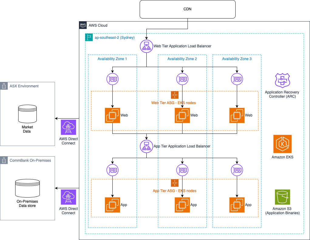
As AWS became CommBank’s preferred cloud provider, the CommSec team rearchitected its app, web, and mobile tiers in early 2025 to run entirely on AWS. With the move to AWS as their sole cloud provider, they took advantage of a new fault isolation boundary to establish a resilience posture similar to what they had with their multicloud solution, but with a simplified architecture.

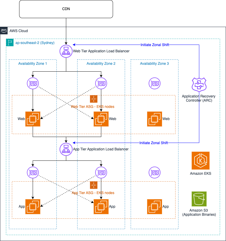
In the previous design, if an issue or outage occurred in a cloud provider or physical data center, traffic was routed and served through the alternate cloud. With the consolidation of the platform on AWS, the CommSec team decided on an Availability Zone as the new fault isolation boundary. Using Amazon Application Recovery Controller (ARC) zonal shift, they can perform a failover to minimize impact to the customer in case of infrastructure or application gray failures while satisfying the requirement to have a physical and logical isolation using multiple Availability Zones in a Region. ARC zonal shift was enabled on their load balancers, so the CommSec team could divert traffic away from an impaired Availability Zone without relying on control plane actions. The same ARC zonal shift capability is being used to help the CommSec team manage application gray failures by reducing customer impact when they occur.
Consolidating on AWS and using ARC zonal shift to manage failures helped the CommSec team realize several important benefits:

  • Out-of-the-box failover capabilities with ARC zonal shift enabled the team to implement comprehensive and automated procedures to move traffic away from an Availability Zone.
  • Comprehensive playbooks that undergo regular validation exercises to verify the effectiveness of the failover procedures and operational readiness.
  • Standardized deployment pipelines and simplified configuration made operating system patching and code deployments two times faster.
  • They saw a 25% base capacity reduction by running the CommSec platform across three AWS Availability Zones compared to two stacks on each public cloud (four stacks) in the past, bringing down operational costs.

The following diagram illustrates the solution architecture.

The CommSec team introduced several resilience improvements:

  • With scale-in and scale-out happening multiple times a day, the process of scaling needed to be as resilient as possible. The CommSec team made sure the entire scale-out bootstrap process had no dependencies on external resources by storing and retrieving application binaries from Amazon Simple Storage Service (Amazon S3) buckets within the same AWS account.
  • Because traffic patterns are incredibly spiky, especially during market open (CommSec traffic often increases threefold between 9:59-10:02 AM on market open), the team implemented Load balancer Capacity Unit (LCU) reservations on the web tier load balancers. This provided sufficient Application Load Balancer (ALB) capacity at the start of the trading day without having to rely on reactive scaling for this predictable spike.
  • They implemented ALB health checks for hard failures to automatically remove instances from target groups. Traffic will shift away from the targets when health checks fail, with alerts signaling the operational team to investigate and remediate.
  • New AWS Direct Connect connections from AWS to the Australian Liquidity Centre (which hosts the Australian Stock Exchange (ASX)’s primary trading, clearing, and settlement systems) were established to improve the reliability of the connectivity to financial markets, including ASX and CBOE exchanges.

ARC zonal shift to help mitigate impairments

In 2023, AWS launched zonal shift, part of Amazon Application Recovery Controller. With zonal shift, you can shift application traffic away from an Availability Zone in a highly available manner for supported resources. This action helps quickly recover an application when an Availability Zone experiences an impairment, reducing the duration and severity of impact to the application due to events such as power outages and hardware or software failures. Zonal shift supports Application and Network Load Balancers, Amazon EC2 Auto Scaling Groups, and Amazon Elastic Kubernetes Service (Amazon EKS).

The CommSec team enabled ARC zonal shift on their ALBs for their web and application tier with cross-zone load balancing enabled. When started, zonal shift takes two actions. First, it removes the IP address of the load balancer node in the specified Availability Zone from DNS, so new queries won’t resolve to that endpoint. This stops future client requests from being sent to that node. Second, it instructs the load balancer nodes in the other Availability Zones not to route requests to targets in the impaired Availability Zone. Cross-zone load balancing is still used in the remaining Availability Zones during the zonal shift, as shown in the following figure.

After the issue is resolved and the application is available again in all Availability Zones, the CommSec team cancels the zonal shift, and traffic is redistributed across all three Availability Zones.

Benefits of ARC zonal shift

ARC zonal shift helps organizations maintain higher availability SLAs, reduce operational costs associated with multi-step manual failover procedures, and minimize revenue loss from service disruptions. The straightforward nature of ARC zonal shift helps teams conduct frequent, on-demand, low-risk testing of their Availability Zone evacuation procedures. The ability to perform regular validation makes sure failover processes remain reliable and builds organizational confidence in disaster recovery capabilities.

“ARC zonal shift is the most efficient way for CommSec to use AWS services whilst meeting our resilience requirements. It provided an out-of-the-box solution that was easier than trying to implement an Availability Zone recovery solution ourselves. Hopefully it’s something we will never need, but our regular resilience testing ensures it’s there and will work if we ever need it.”

– Henry Zhao, CommBank Staff Software Engineer.

Conclusion

By using AWS services and implementing a robust Multi-AZ architecture, the CommSec trading platform continues to meet the demanding needs of Australia’s leading online broker. The combination of ARC zonal shift capabilities, optimized load balancer configurations, and comprehensive runbooks and operational procedures has enabled CommSec to maintain exceptional reliability while serving over millions of customers. CommSec’s journey showcases how careful architectural decisions and AWS managed services can help organizations achieve both operational excellence and superior customer experience for mission-critical financial applications.

To learn more, refer to AWS Fault Isolation Boundaries and Amazon Application Recovery Controller.


About the authors

Introducing Amazon Application Recovery Controller Region switch: A multi-Region application recovery service
Post Syndicated from Sébastien Stormacq original https://aws.amazon.com/blogs/aws/introducing-amazon-application-recovery-controller-region-switch-a-multi-region-application-recovery-service/

As a developer advocate at AWS, I’ve worked with many enterprise organizations who operate critical applications across multiple AWS Regions. A key concern they often share is the lack of confidence in their Region failover strategy—whether it will work when needed, whether all dependencies have been identified, and whether their teams have practiced the procedures enough. Traditional approaches often leave them uncertain about their readiness for Regional switch.

Today, I’m excited to announce Amazon Application Recovery Controller (ARC) Region switch, a fully managed, highly available capability that enables organizations to plan, practice, and orchestrate Region switches with confidence, eliminating the uncertainty around cross-Region recovery operations. Region switch helps you orchestrate recovery for your multi-Region applications on AWS. It gives you a centralized solution to coordinate and automate recovery tasks across AWS services and accounts when you need to switch your application’s operations from one AWS Region to another.
Many customers deploy business-critical applications across multiple AWS Regions to meet their availability requirements. When an operational event impacts an application in one Region, switching operations to another Region involves coordinating multiple steps across different AWS services, such as compute, databases, and DNS. This coordination typically requires building and maintaining complex scripts that need regular testing and updates as applications evolve. Additionally, orchestrating and tracking the progress of Region switches across multiple applications and providing evidence of successful recovery for compliance purposes often involves manual data gathering.

Region switch is built on a Regional data plane architecture, where Region switch plans are executed from the Region being activated. This design eliminates dependencies on the impacted Region during the switch, providing a more resilient recovery process since the execution is independent of the Region you’re switching from.

Building a recovery plan with ARC Region switch
With ARC Region switch, you can create recovery plans that define the specific steps needed to switch your application between Regions. Each plan contains execution blocks that represent actions on AWS resources. At launch, Region switch supports nine types of execution blocks:

  • ARC Region switch plan execution block–let you orchestrate the order in which multiple applications switch to the Region you want to activate by referencing other Region switch plans.
  • Amazon EC2 Auto Scaling execution block–Scales Amazon EC2 compute resources in your target Region by matching a specified percentage of your source Region’s capacity.
  • ARC routing controls execution block–Changes routing control states to redirect traffic using DNS health checks.
  • Amazon Aurora global database execution block–Performs database failover with potential data loss or switchover with zero data loss for Aurora Global Database.
  • Manual approval execution block–Adds approval checkpoints in your recovery workflow where team members can review and approve before proceeding.
  • Custom Action AWS Lambda execution block–Adds custom recovery steps by executing Lambda functions in either the activating or deactivating Region.
  • Amazon Route 53 health check execution block–Let you to specify which Regions your application’s traffic will be redirected to during failover. When executing your Region switch plan, the Amazon Route 53 health check state is updated and traffic is redirected based on your DNS configuration.
  • Amazon Elastic Kubernetes Service (Amazon EKS) resource scaling execution block–Scales Kubernetes pods in your target Region during recovery by matching a specified percentage of your source Region’s capacity.
  • Amazon Elastic Container Service (Amazon ECS) resource scaling execution block–Scales ECS tasks in your target Region by matching a specified percentage of your source Region’s capacity.

Region switch continually validates your plans by checking resource configurations and AWS Identity and Access Management (IAM) permissions every 30 minutes. During execution, Region switch monitors the progress of each step and provides detailed logs. You can view execution status through the Region switch dashboard and at the bottom of the execution details page.

To help you balance cost and reliability, Region switch offers flexibility in how you prepare your standby resources. You can configure the desired percentage of compute capacity to target in your destination Region during recovery using Region switch scaling execution blocks. For critical applications expecting surge traffic during recovery, you might choose to scale beyond 100 percent capacity, and setting a lower percentage can help achieve faster overall execution times. However, it’s important to note that using one of the scaling execution blocks does not guarantee capacity, and actual resource availability depends on the capacity in the destination Region at the time of recovery. To facilitate the best possible outcomes, we recommend regularly testing your recovery plans and maintaining appropriate Service Quotas in your standby Regions.

ARC Region switch includes a global dashboard you can use to monitor the status of Region switch plans across your enterprise and Regions. Additionally, there’s a Regional executions dashboard that only displays executions within the current console Region. This dashboard is designed to be highly available across each Region so it can be used during operational events.

Region switch allows resources to be hosted in an account that is separate from the account that contains the Region switch plan. If the plan uses resources from an account that is different from the account that hosts the plan, then Region switch uses the executionRole to assume the crossAccountRole to access those resources. Additionally, Region switch plans can be centralized and shared across multiple accounts using AWS Resource Access Manager (AWS RAM), enabling efficient management of recovery plans across your organization.

Let’s see how it works
Let me show you how to create and execute a Region switch plan. There are three parts in this demo. First, I create a Region switch plan. Then, I define a workflow. Finally, I configure the triggers.

Step 1: Create a plan

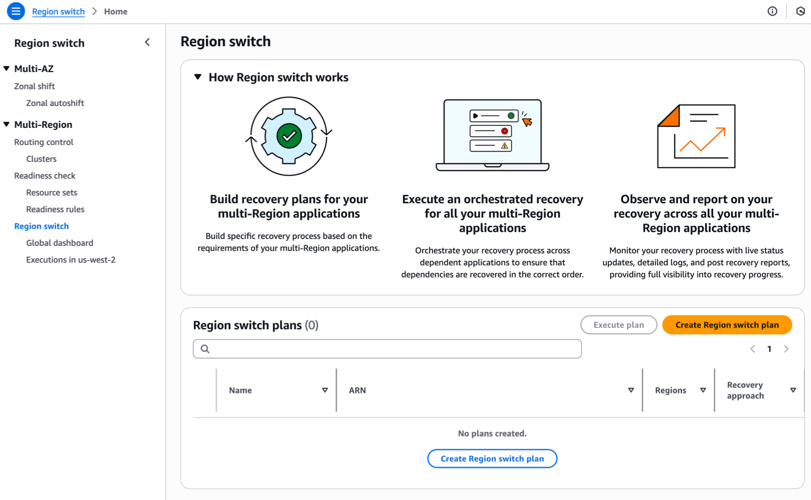
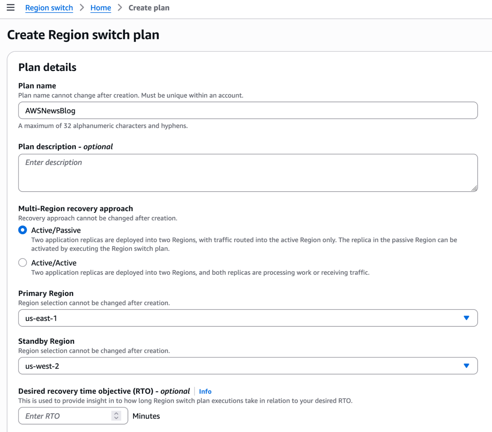
I navigate to the Application Recovery Controller section of the AWS Management Console. I choose Region switch in the left navigation menu. Then, I choose Create Region switch plan.

ARC Region switch - 1

After I give a name to my plan, I specify a Multi-Region recovery approach (active/passive or active/active). In Active/Passive mode, two application replicas are deployed into two Regions, with traffic routed into the active Region only. The replica in the passive Region can be activated by executing the Region switch plan.

Then, I select the Primary Region and Standby Region. Optionally, I can enter a Desired recovery time objective (RTO). The service will use this value to provide insight into how long Region switch plan executions take in relation to my desired RTO.

ARC Region switch - create plan

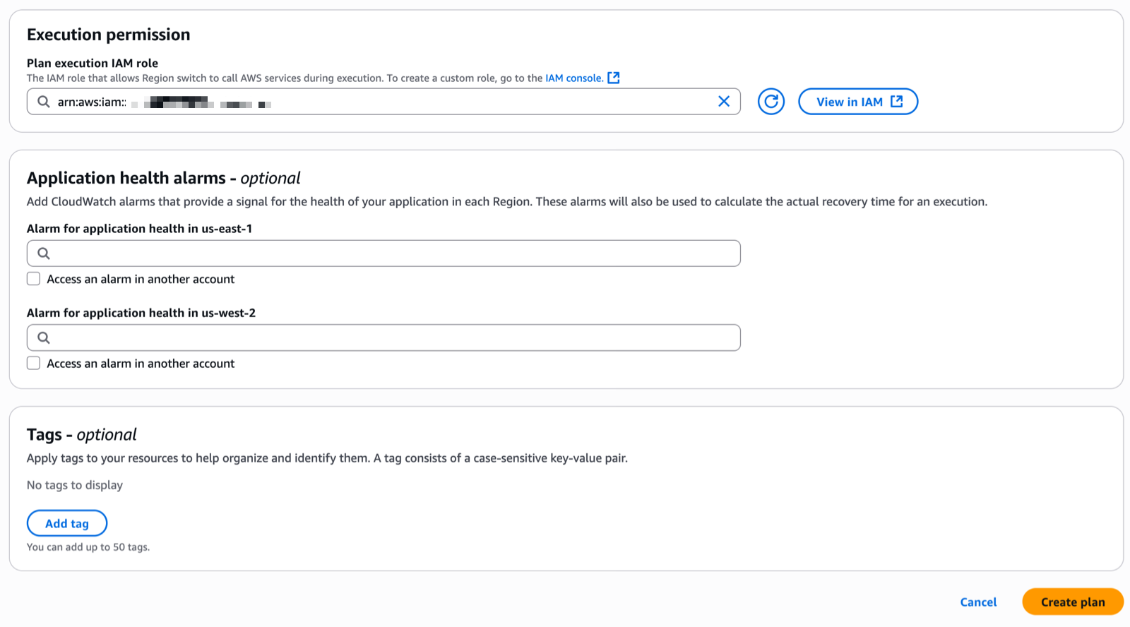
I enter the Plan execution IAM role. This is the role that allows Region switch to call AWS services during execution. I make sure the role I choose has permissions to be invoked by the service and contains the minimum set of permissions allowing ARC to operate. Refer to the IAM permissions section of the documentation for the details.

ARC Region switch - create plan 2Step 2: Create a workflow

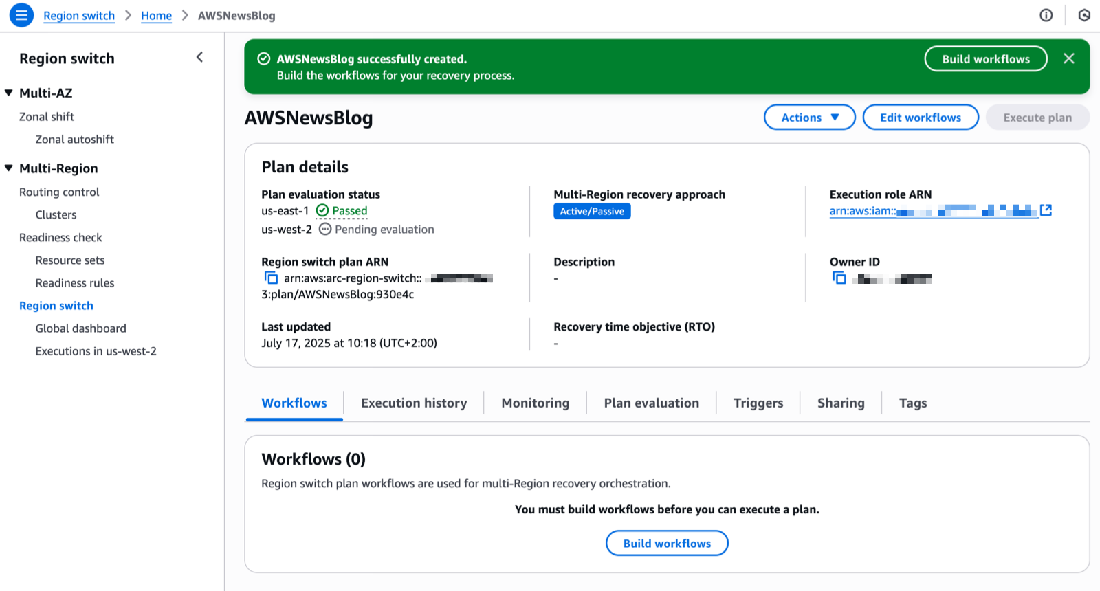
When the two Plan evaluation status notifications are green, I create a workflow. I choose Build workflows to get started.


ARC Region switch - status

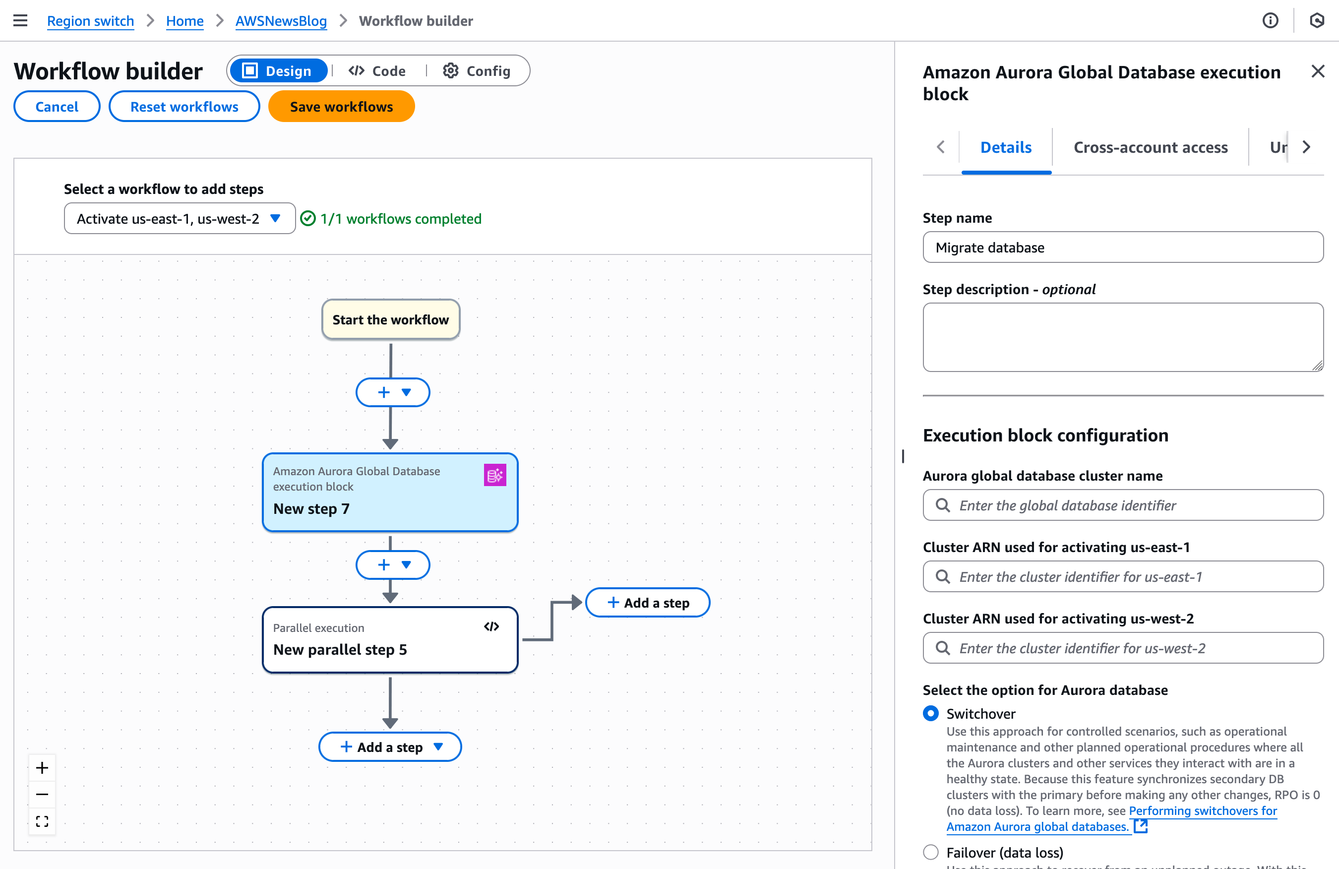
Plans enable you to build specific workflows that will recover your applications using Region switch execution blocks. You can build workflows with execution blocks that run sequentially or in parallel to orchestrate the order in which multiple applications or resources recover into the activating Region. A plan is made up of these workflows that allow you to activate or deactivate a specific Region.

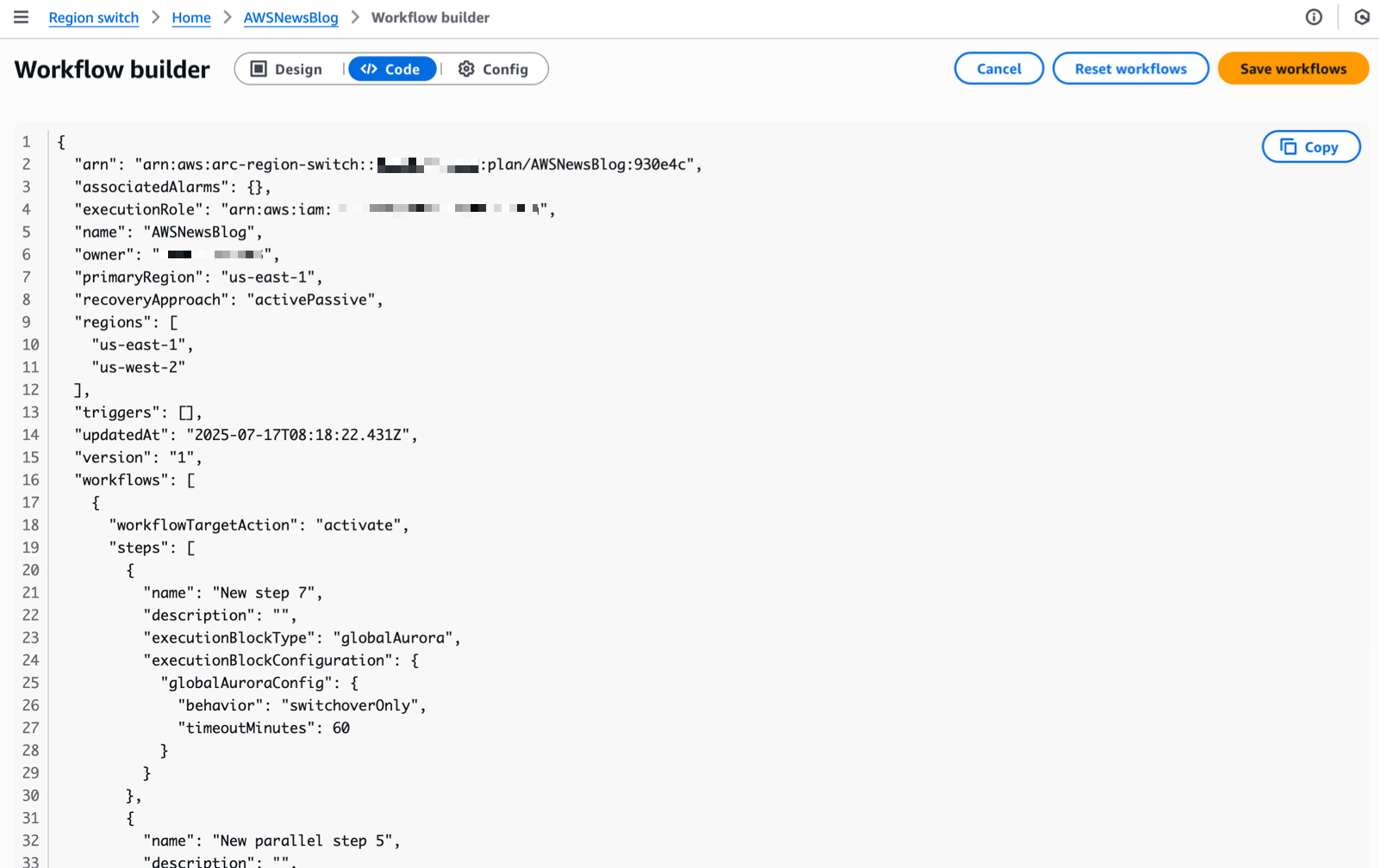
For this demo, I use the graphical editor to create the workflow. But you can also define the workflow in JSON. This format is better suited for automation or when you want to store your workflow definition in a source code management system (SCMS) and your infrastructure as code (IaC) tools, such as AWS CloudFormation.

ARC - define workflows

I can alternate between the Design and the Code views by selecting the corresponding tab next to the Workflow builder title. The JSON view is read-only. I designed the workflow with the graphical editor and I copied the JSON equivalent to store it alongside my IaC project files.

ARC - define workflows as code

Region switch launches an evaluation to validate your recovery strategy every 30 minutes. It regularly checks that all actions defined in your workflows will succeed when executed. This proactive validation assesses various elements, including IAM permissions and resource states across accounts and Regions. By continually monitoring these dependencies, Region switch helps ensure your recovery plans remain viable and identifies potential issues before they impact your actual switch operations.

However, just as an untested backup is not a reliable backup, an untested recovery plan cannot be considered truly validated. While continuous evaluation provides a strong foundation, we strongly recommend regularly executing your plans in test scenarios to verify their effectiveness, understand actual recovery times, and ensure your teams are familiar with the recovery procedures. This hands-on testing is essential for maintaining confidence in your disaster recovery strategy.

Step 3: Create a trigger

A trigger defines the conditions to activate the workflows just created. It’s expressed as a set of CloudWatch alarms. Alarm-based triggers are optional. You can also use Region switch with manual triggers.

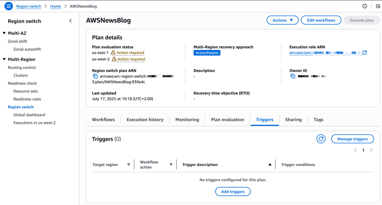
From the Region switch page in the console, I choose the Triggers tab and choose Add triggers.

ARC - Trigger

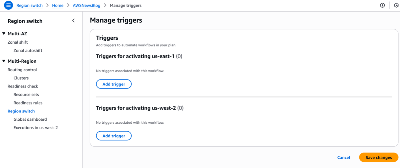
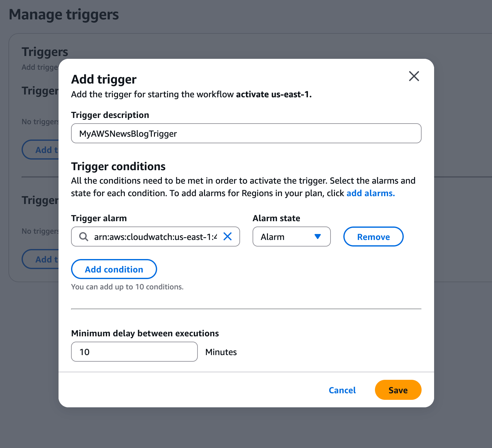
For each Region defined in my plan, I choose Add trigger to define the triggers that will activate the Region.ARC - Trigger 2Finally, I choose the alarms and their state (OK or Alarm) that Region switch will use to trigger the activation of the Region.

ARC - Trigger 3

I’m now ready to test the execution of the plan to switch Regions using Region switch. It’s important to execute the plan from the Region I’m activating (the target Region of the workflow) and use the data plane in that specific Region.

Here is how to execute a plan using the AWS Command Line Interface (AWS CLI):

aws arc-region-switch start-plan-execution \
--plan-arn arn:aws:arc-region-switch::111122223333:plan/resource-id \
--target-region us-west-2 \
--action activate

Pricing and availability
Region switch is available in all commercial AWS Regions at $70 per month per plan. Each plan can include up to 100 execution blocks, or you can create parent plans to orchestrate up to 25 child plans.

Having seen firsthand the engineering effort that goes into building and maintaining multi-Region recovery solutions, I’m thrilled to see how Region switch will help automate this process for our customers. To get started with ARC Region switch, visit the ARC console and create your first Region switch plan. For more information about Region switch, visit the Amazon Application Recovery Controller (ARC) documentation. You can also reach out to your AWS account team with questions about using Region switch for your multi-Region applications.
I look forward to hearing about how you use Region switch to strengthen your multi-Region applications’ resilience.

— seb

How HashiCorp made cross-Region switchover seamless with Amazon Application Recovery Controller
Post Syndicated from Dmitriy Novikov original https://aws.amazon.com/blogs/architecture/how-hashicorp-made-cross-region-switchover-seamless-with-amazon-application-recovery-controller/

This blog was co-authored by Brandon Raabe, Sr. Site Reliability Engineer at HashiCorp.

In cloud-based systems, minutes of downtime can translate to significant business impact and eroded customer trust. HashiCorp, a leader in multicloud infrastructure automation software, faced this critical challenge as their HashiCorp Cloud Platform (HCP) scaled to serve enterprise customers with stringent availability requirements. When Regional outages threatened service continuity, the complex dance of failing over DNS entries, workloads, and databases across AWS Regions had become an error-prone process requiring intense coordination. This post chronicles how HashiCorp’s Site Reliability Engineering (SRE) team transformed their disaster recovery capabilities by implementing Amazon Application Recovery Controller (ARC), creating a solution that not only dramatically simplified cross-Region failovers but also provided a standardized way to signal Regional context to their distributed services.
In this post, we discuss HashiCorp’s journey from manual, stress-inducing failover procedures to a streamlined, confident approach that fundamentally changed how they deliver on their enterprise-grade resilience promises.

Challenges with disaster recovery in a multicloud infrastructure

HashiCorp’s SRE team recognized that as their cloud platform scaled to serve mission-critical enterprise workloads, their disaster recovery approach needed an upgrade. The existing manual processes required precise coordination across multiple systems during already stressful outage scenarios, which could lead to potential complications when speed and accuracy matter most. Regional outages posed particular challenges: if the control planes for critical services became unavailable, the very tools needed to execute recovery might be inaccessible.

ARC emerged as the ideal solution with its unique architecture: a highly available data plane accessible through endpoints in five distinct Regions, so the recovery mechanism remains operational even during significant Regional disruptions. By using the AWS SDK to interface with ARC, HashiCorp gained several critical advantages. They could apply infrastructure as code (IaC) practices to disaster recovery workflows, automate testing of failover procedures, and integrate resilience seamlessly with their existing operational tooling. This solution transformed their disaster recovery from a specialized manual procedure into a codified, repeatable process embedded within their platform operations.

Requirements and architectural considerations

After evaluating multiple disaster recovery approaches, HashiCorp established three core requirements for their solution. First, while maintaining human judgment for initiating failovers, the execution needed to proceed without additional operator interventions after it was triggered. This human-in-the-loop design preserved deliberate decision-making while reducing error-prone manual steps during implementation.

Second, the architecture needed exceptional resilience against the very failures it was designed to mitigate. Traditional DNS failover solutions presented a critical vulnerability: dependency on single-Region control planes that might be unavailable during an outage. ARC solved this problem through its distributed architecture, connecting Amazon Route 53 to a resilient control mechanism, enabled by Route 53 health checks, accessible through multiple Regional endpoints. This means the failover system itself remained available even if the primary Region went offline.

Third, the solution needed to meet or exceed HashiCorp’s existing Recovery Point Objective (RPO) and Recovery Time Objective (RTO) metrics—the maximum acceptable data loss and downtime thresholds. Using ARC, the SRE team planned to not just reach these targets but make substantial improvements, reducing potential customer impact during Regional events and strengthening HashiCorp’s enterprise-grade resilience.

Solution overview

To transform their disaster recovery posture, HashiCorp’s SRE team designed an architecture centered around ARC and complemented by a purpose-built orchestration service. This architecture seamlessly bridges the human decision to initiate failover with the complex technical operations required to shift traffic between Regions with minimal disruption.

At the heart of the solution is a custom failover service that serves as the orchestration layer for Regional transitions. This service maintains configuration details for the ARC cluster and provides a single, controlled interface for initiating Regional switchovers. When activated, the service establishes a secure connection to the ARC API endpoints and executes a two-step workflow: first disabling routing controls for the primary Region, then enabling those for the secondary Region. This sequential approach provides a clean traffic transition without split-brain scenarios or dropped connections.

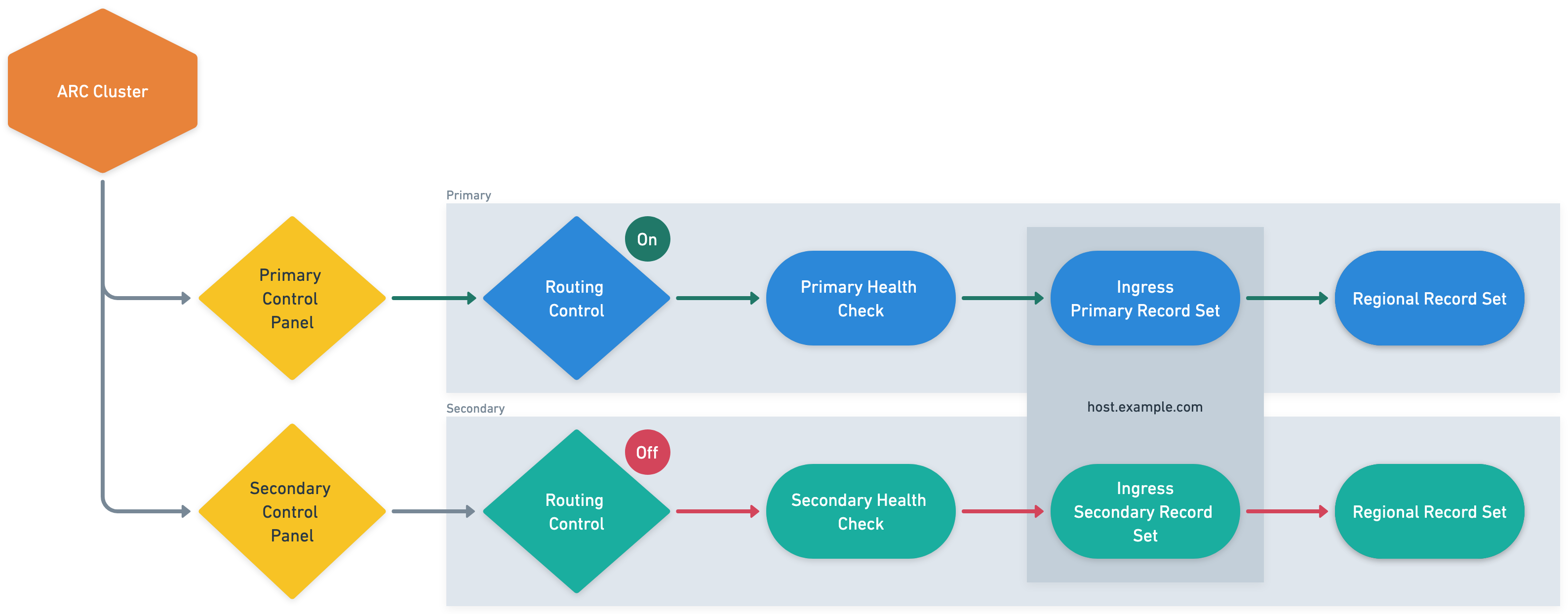
The DNS architecture underwent a strategic evolution to support this new capability. HashiCorp reconfigured their critical ingress endpoints as Route 53 failover record pairs, with each pair consisting of a primary and secondary record. Each record is linked to a health check that monitors the state of an ARC routing control—effectively connecting AWS’s global DNS service to the ARC routing control. The primary records resolve to endpoints in the primary Region, and secondary records point to corresponding infrastructure in the standby Region. When routing controls change state, the associated health checks automatically trigger Route 53 to adjust DNS resolution patterns, redirecting traffic to the appropriate Regional infrastructure.

HashiCorp maintains their secondary Region in a warm standby configuration, with essential services running but not actively serving client traffic until a failover event occurs. To enable seamless awareness of Region status across their distributed system, the team implemented a signaling mechanism using specially crafted TXT DNS records. These records are tied to the same ARC routing controls as the primary service endpoints, effectively creating a discoverable, global state indicator. Services can query these TXT records to dynamically determine the currently active Region and adjust their internal routing, replication, and operational behaviors accordingly — alleviating the need for a separate configuration distribution system and making sure all components have a consistent view of the current Regional state.

The following diagram illustrates the disaster recovery workflow.

This architecture combines human oversight for initiating critical Regional transitions with fully automated execution after the decision is made. The use of ARC’s globally distributed control plane removes single-Region dependencies that might otherwise compromise the failover mechanism itself during a Regional outage event.

Operational decision framework for Regional failover

HashiCorp’s Regional failover process balances automated monitoring with deliberate human decision-making. Their comprehensive observability platform continuously monitors Regional health, automatically alerting the incident response team when anomalies are detected. When alerts trigger, the incident management protocol activates, with an incident commander quickly assembling experts to assess the situation.

The team follows a structured evaluation framework to determine if failover is warranted: confirming the issue is Region-specific, verifying that redundant intra-Region components can’t mitigate the problem, and assessing whether the projected Regional recovery time exceeds acceptable customer impact thresholds. This approach prevents unnecessary Regional transitions while providing rapid action when genuinely needed.

After the decision to failover is made, an authorized operator initiates the process through a single API call to their orchestration service, which then interfaces with ARC to execute the complex sequence of routing control changes. This design preserves human judgment for the critical decision while using automation for precise execution, so HashiCorp can respond confidently and consistently during high-pressure Regional outage scenarios.

Disaster recovery testing

HashiCorp maintains operational readiness through a disciplined monthly disaster recovery testing program in their integration environment. One week before each scheduled test, the team notifies all stakeholders to confirm organization-wide awareness and participation. On test day, they follow formal incident protocols, creating dedicated communication channels for transparent observation and collaboration.

The test execution mirrors their production failover process: an operator initiates the recovery sequence through their API, activating the ARC routing controls to shift traffic to the secondary Region. What sets HashiCorp’s approach apart is their comprehensive validation methodology. The team verifies critical services in the secondary Region and then fails back to the primary Region with subsequent validation. This bidirectional testing confirms both failover and failback procedures work reliably.

Each exercise concludes with a structured retrospective where the team documents observations and identifies improvement opportunities. By treating these tests as learning experiences rather than compliance activities, HashiCorp has established a continuous improvement cycle for their disaster recovery capabilities. The insights from these regular drills have led to numerous refinements in their ARC implementation and operational procedures, so their team can respond confidently during actual outages with practiced, predictable procedures.

Conclusion

The collaboration between HashiCorp and AWS through ARC has revolutionized HashiCorp’s disaster recovery capabilities. Regional transitions that once required careful DNS record manipulation by specialized operators now execute through a single API call, with traffic shifting within seconds and full propagation completing in approximately 2 minutes. This dramatic simplification, achieved by integrating the resilient ARC architecture with HashiCorp’s custom orchestration service, has not only improved recovery metrics but has also strengthened their enterprise-grade resilience promises.

ARC has solved a fundamental distributed systems challenge by providing a reliable mechanism for services to determine the active Region. By linking ARC routing controls to specialized TXT records, HashiCorp created a consistent global indicator that allows services to automatically adjust their behavior without additional coordination systems—simplifying their architecture and reducing dependencies.

Most significantly, this implementation has democratized disaster recovery within HashiCorp, transforming it from a specialized capability to a standardized procedure executable by their regular on-call rotation. The solution’s highly available endpoints across multiple Regions makes sure the recovery mechanism itself remains operational even during severe outages—addressing a critical vulnerability in their previous approach.

For HashiCorp’s enterprise customers, these improvements translate directly to business value: reduced recovery times during Regional events, increased operational confidence, and assurance that their critical infrastructure management tools will remain available even during major cloud disruptions. As HashiCorp continues to refine their approach through rigorous testing and continuous improvement, their ARC implementation demonstrates how thoughtfully architected disaster recovery can evolve from merely an insurance policy into a strategic competitive advantage.

To learn more, visit Amazon Application Recovery Controller, AWS Multi-Region Capabilities, and AWS multi-Region fundamentals.


About the authors

Build a multi-Region AWS PrivateLink backed service with seamless failover

Post Syndicated from Madhav Vishnubhatta original https://aws.amazon.com/blogs/architecture/build-a-multi-region-aws-privatelink-backed-service-with-seamless-failover/

Global Payments Inc. is a leading worldwide provider of payment technology and software solutions, headquartered in Atlanta, Georgia. The company processes more than 75 billion transactions annually, serving more than 5 million merchant locations and nearly 2,000 financial institutions globally. Through its merger with TSYS in 2019, Global Payments expanded its capabilities beyond merchant acquiring services to include issuer processing solutions.

The company’s services now encompass ecommerce and omnichannel payments, business management software, customer engagement tools, and cloud-based solutions. Their commitment to technological innovation and customer service has positioned them as one of the largest financial technology companies globally, consistently ranking among the Fortune 500.

This post demonstrates how the Issuer Solutions business of Global Payments, as a service provider, implemented cross-Region failover for an AWS PrivateLink backed service exposed to their customers. Their solution enables failover to a secondary Region without customer coordination, reducing Recovery Time Objective (RTO).

AWS PrivateLink involves two key roles: service providers and service consumers. Service providers build, own, and manage endpoint services. Service consumers create and manage Amazon Virtual Private Cloud (Amazon VPC) endpoints that connect their VPC to an Amazon VPC endpoint service privately, without exposing the traffic to the public internet. Enterprises often build services in multiple AWS Regions for resilience. This approach requires endpoint services in two Regions, with service consumers creating VPC endpoints for each service.

The architecture uses Amazon Route 53 to resolve the service’s Fully Qualified Domain Name (FQDN) to the active Region’s service. Amazon Application Recovery Controller (ARC) is used to initiate the failover.
Customer requirements

Issuer Solutions had the following requirements for this implementation:

  • The ability for consumers to access the service privately, without traversing the public internet
  • Resilience to degradation in a single Region by allowing failover to a secondary Region
  • Independent failover without customer coordination
  • Reliable and simple failover process

Solution overview

The following simplified architecture diagram illustrates the connectivity and failover mechanisms. The exact service implementation of Issuer Solutions is beyond this post’s scope. For simplicity, we represent the service as a Network Load Balancer backed by Amazon Elastic Compute Cloud (Amazon EC2) instances.

AWS Architecture diagram showing primary and secondary regions with Route53 Private Hosted Zones, VPC endpoints, and PrivateLink integration, illustrating the connectivity and failover mechanisms.

The solution consists of the following key components:

  • The service provider deploys identical services in two Regions. The service is represented in this simplified version with a Network Load Balancer backed by EC2 instances. Each Region is independent and therefore resilient against failures in the other Region.
  • Services are exposed through PrivateLink as VPC endpoint services in each Region, allowing client connections without needing NAT gateways or internet gateways and keeping the traffic within the customers’ own private IP space.
  • The service provider authorizes the consumer AWS account to find the services using the VPC endpoint service names.
  • The service consumer uses the VPC PrivateLink endpoint service names to create VPC endpoints with Elastic Network Interfaces (ENIs) in two Availability Zones in each Region. The consumer does this in both consumer Regions, and each consumer Region has two sets of VPC endpoints: one for the primary service of the provider and one for the secondary service.
  • The service consumer creates a Route 53 private hosted zone in each of the two Regions they use, each with two alias records, with a simple routing policy, pointing to the VPC endpoints’ FQDNs in their own Regions. These two alias records are primary.example.com and secondary.example.com.
  • The service provider creates a Route 53 ARC cluster with routing controls for the primary and secondary Regions.
  • The service provider creates a private hosted zone with a failover record set for a consumer specific CNAME like custC.service.p.com that resolves to primary.example.com and secondary.example.com. These records are associated with health checks that are associated with Route 53 ARC routing controls.

As shown in the architecture diagram, it is not necessary for the provider’s and consumer’s Regions to be the same because AWS supports creating VPC endpoints in a Region different to that of the VPC endpoint service itself. Refer to AWS PrivateLink now supports cross-region connectivity for more details.

How the DNS resolution works

Each consumer Region has two Route 53 private hosted zones involved in DNS resolution in this approach: the service provider’s hosted zone and the service consumer’s hosted zone. Both hosted zones are associated with the VPC used by the service consumer. Here is how the DNS resolution works:

  1. When a client in the consumer VPC wants to reach the service, it uses the FQDN custC.service.p.com.
  2. The hosted zone in the service provider’s account resolves custC.service.p.com to either primary.example.com or secondary.example.com depending on the status of the health checks controlled by ARC. For now, let’s assume this resolves to primary.example.com.
  3. Next, primary.example.com resolves to the VPC endpoint FQDN com.amazonaws.vpce.<primary-region>.vpce-svcabc123 due to the hosted zone in the service consumer.

At the time of failover, the service provider will update the ARC health checks to turn off the primary control and turn on the secondary routing control. This causes the service provider’s hosted zone to resolve custC.service.p.com to secondary.example.com, which in turn resolves to the VPC endpoint FQDN in the secondary Region due to the service consumer’s hosted zone.

Considerations

With this setup, the service provider can fail over when they need to without the service consumer having to manually make any changes. This is especially useful for services that have multiple service consumers. Additionally, service consumers can make changes to the VPC endpoint as they see fit. They only need to update the hosted zone they manage to make sure that primary.example.com and secondary.example.com point to the correct VPC endpoints.

We used ARC in this post because it offers a robust solution for cross-Region failover with built-in static stability. ARC also avoids single points of failure in the failover logic by distributing it across multiple Regions.

This setup demonstrates an active-passive configuration where traffic is routed to a single Region at a time using the Route 53 failover routing policy. For an active-active approach, you can adapt this setup by employing alternative Route 53 policies such as weighted or latency-based routing, as detailed in Active-active and active-passive failover.

Code sample

We have created a GitHub repository with Terraform code to demonstrate this solution. The repository has the steps to set it up and test it.

Conclusion

This implementation of cross-Region failover by Global Payments Issuer Solutions for their PrivateLink backed service demonstrates a robust and flexible approach to providing high availability and resilience. By using AWS services such as PrivateLink, Route 53, and Route 53 ARC, they have created a solution that meets their key requirements. This architecture not only benefits Global Payments by allowing them to manage failovers efficiently, but also provides advantages to their service consumers. Customers maintain control over their own infrastructure while benefiting from seamless service continuity. As cloud architectures continue to evolve, solutions like this showcase the power of combining various AWS services to create highly available and fault-tolerant systems that meet complex business needs.

Clone our GitHub repository now and deploy this solution in your own AWS environment to try out this approach to cross-Region failover. Contact your AWS representative today to begin your journey toward enhanced business continuity.


About the Authors