Tag Archives: Networking & Content Delivery*

Introducing Amazon Route 53 Global Resolver for secure anycast DNS resolution (preview)

Post Syndicated from Esra Kayabali original https://aws.amazon.com/blogs/aws/introducing-amazon-route-53-global-resolver-for-secure-anycast-dns-resolution-preview/

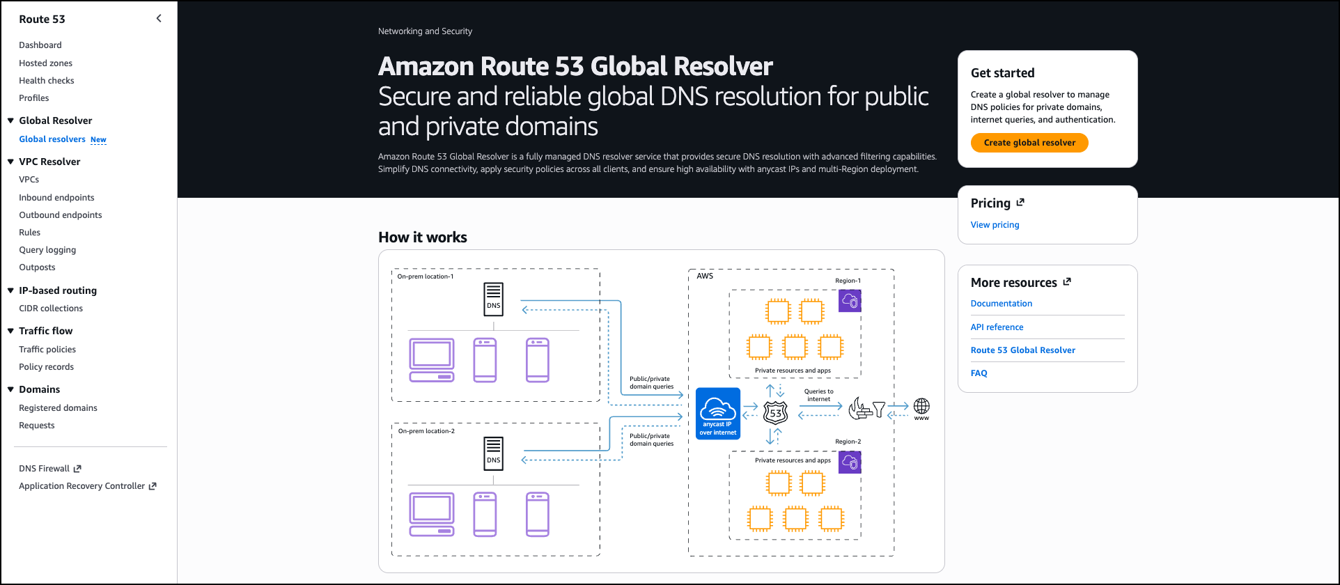
Today, we’re announcing Amazon Route 53 Global Resolver, a new Amazon Route 53 service that provides secure and reliable DNS resolution globally for queries from anywhere (preview). You can use Global Resolver to resolve DNS queries to public domains on the internet and private domains associated with Route 53 private hosted zones. Route 53 Global Resolver offers network administrators a unified solution to resolve queries from authenticated clients and sources in on-premises data centers, branch offices, and remote locations through globally distributed anycast IP addresses. This service includes built-in security controls including DNS traffic filtering, support for encrypted queries, and centralized logging to help organizations reduce operational overhead while maintaining compliance with security requirements.

Organizations with hybrid deployments face operational complexity when managing DNS resolution across distributed environments. Resolving public internet domains and private application domains often requires maintaining split DNS infrastructure, which increases cost and administrative burden especially when replicating to multiple locations. Network administrators must configure custom forwarding solutions, deploy Route 53 Resolver endpoints for private domain resolution, and implement separate security controls across different locations. Additionally, they must configure and maintain multi-Region failover strategies for Route 53 Resolver endpoints and provide consistent security policy enforcement across all Regions while testing failover scenarios.

Route 53 Global Resolver has key capabilities that address these challenges. The service resolves both public internet domains and Route 53 private hosted zones, eliminating the need for separate split-DNS forwarding. It provides DNS resolution through multiple protocols, including DNS over UDP (Do53), DNS-over-HTTPS (DoH), and DNS-over-TLS (DoT). Each deployment provides a single set of common IPv4 and IPv6 anycast IP addresses that route queries to the nearest AWS Region, reducing latency for distributed client populations.

Route 53 Global Resolver provides integrated security features equivalent to Route 53 Resolver DNS Firewall. Administrators can configure filtering rules using AWS Managed Domain Lists that provide flexible controls with lists classified by DNS threats (malware, spam, phishing) or web content (adult sites, gambling, social networking) that might not be safe for work or create custom domain lists by importing domains from a file. Advanced threat protection detects and blocks domain generation algorithm (DGA) patterns and DNS tunneling attempts. For encrypted DNS traffic, Route 53 Global Resolver supports DoH and DoT protocols to protect queries from unauthorized access during transit.

Route 53 Global Resolver only accepts traffic from known clients that need to authenticate with the Resolver. For Do53, DoT, and DoH connections, administrators can configure IP and CIDR allowlists. For DoH and DoT connections, token-based authentication provides granular access control with customizable expiration periods and revocation capabilities. Administrators can assign tokens to specific client groups or individual devices based on organizational requirements.

Route 53 Global Resolver supports DNSSEC validation to verify the authenticity and integrity of DNS responses from public nameservers. It also includes EDNS Client Subnet support, which forwards client subnet information to enable more accurate geographic-based DNS responses from content delivery networks.

Getting started with Route 53 Global Resolver
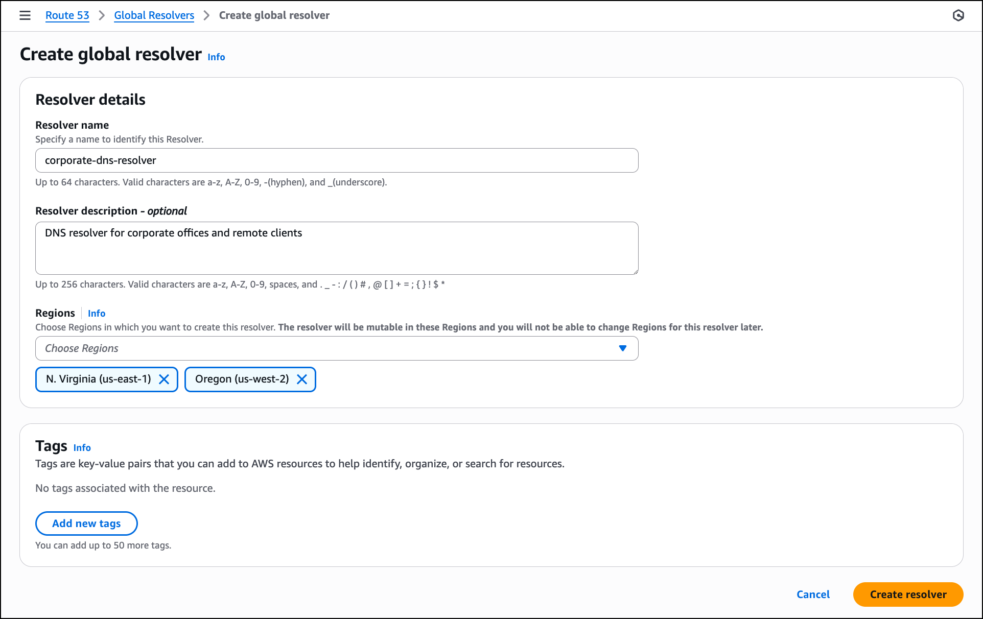
This walkthrough shows how to configure Route 53 Global Resolver for an organization with offices on the US East and West coasts that needs to resolve both public domains and private applications hosted in Route 53 private hosted zones. To configure Route 53 Global Resolver, go to the AWS Management Console, choose Global resolvers from the navigation pane, and choose Create global resolver.

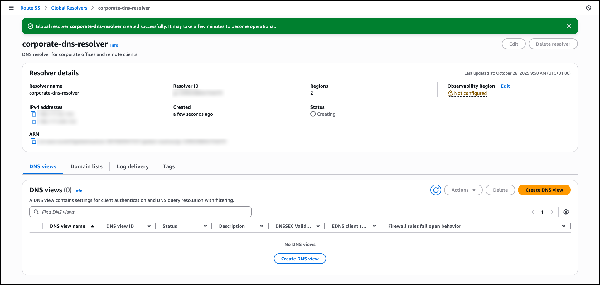
In the Resolver details section, enter a Resolver name such as corporate-dns-resolver. Add an optional description like DNS resolver for corporate offices and remote clients. In the Regions section, choose the AWS Regions where you want the resolver to operate, such as US East (N. Virginia) and US West (Oregon). The anycast architecture routes DNS queries from your clients to the nearest selected Region.

After the resolver is created, the console displays the resolver details, including the anycast IPv4 and IPv6 addresses that you will use for DNS queries. You can proceed to create a DNS view by choosing Create DNS view to configure client authentication and DNS query resolution settings.

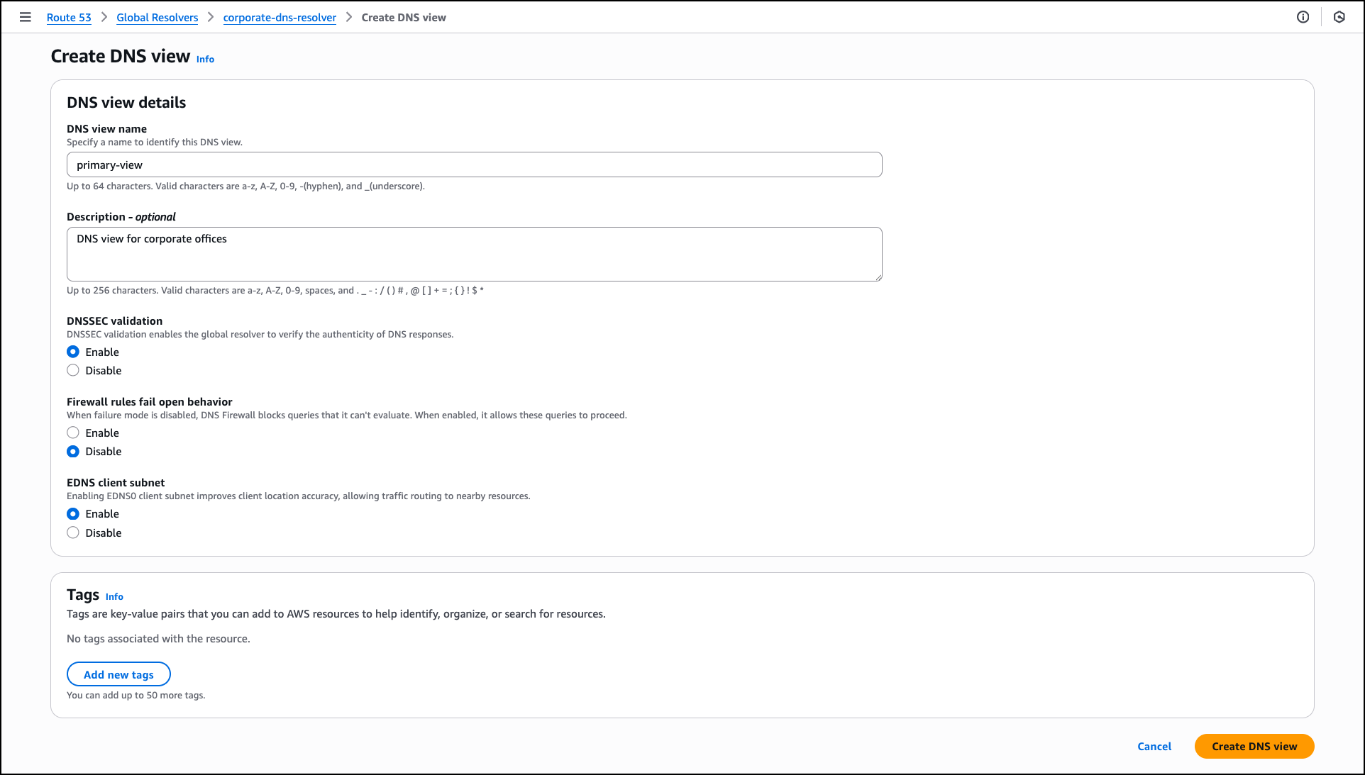
In the Create DNS view section, enter a DNS view name such as primary-view and optionally add a Description like DNS view for corporate offices. A DNS view helps you create different logical groupings for your clients and sources, and determine the DNS resolution for those groups. This helps you maintain different DNS filtering rules and private hosted zone resolution policies for different clients in your organization.

For DNSSEC validation, choose Enable to verify the authenticity of DNS responses from public DNS servers. For Firewall rules fail open behavior, choose Disable to block DNS queries when firewall rules can’t be evaluated, which provides additional security. For EDNS client subnet, keep Enable selected to forward client location information to DNS servers, which allows content delivery networks to provide more accurate geographic responses. DNS view creation might take a few minutes to become operational.

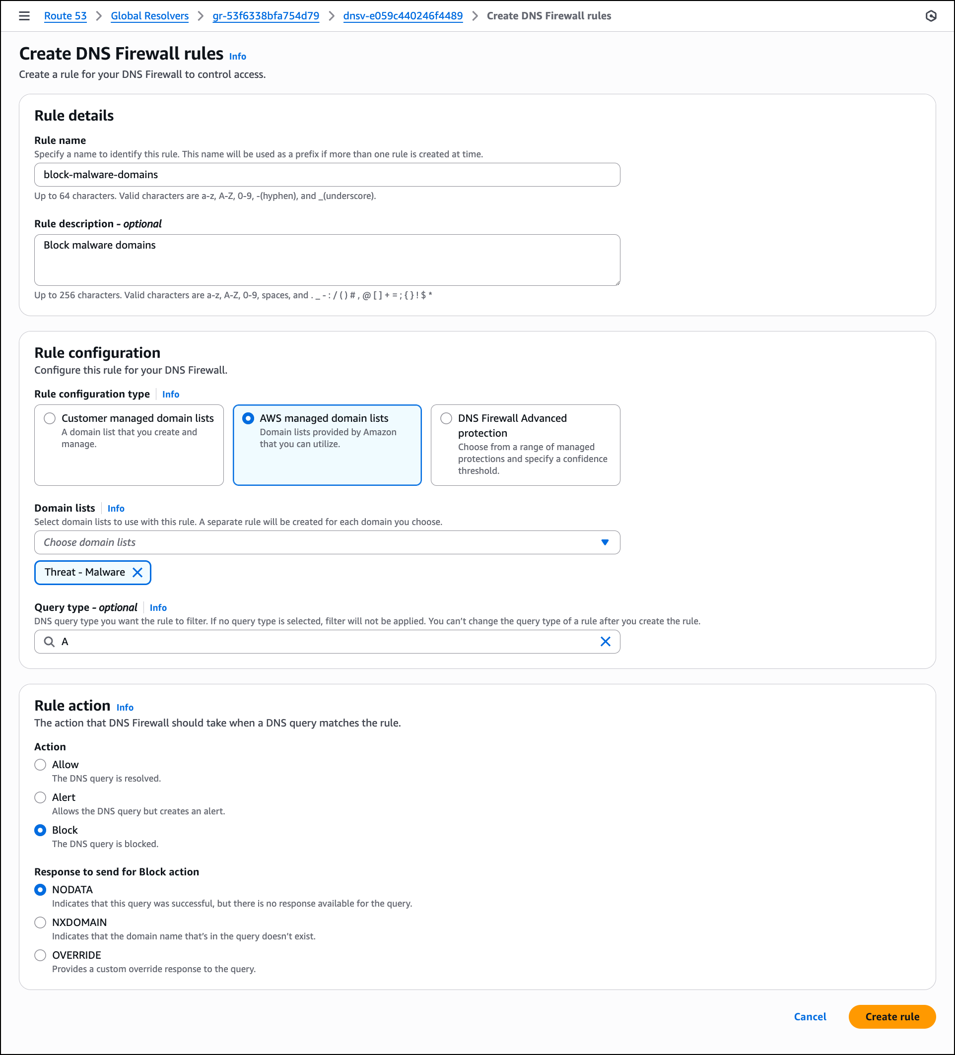
After the DNS view is created and operational, configure DNS Firewall rules to filter network traffic by choosing Create rule. In the Create DNS Firewall rules section, enter a Rule name such as block-malware-domains and optionally add a description. For Rule configuration type, you can choose Customer managed domain lists, AWS managed domain lists provided by AWS or DNS Firewall Advanced protection.

For this walkthrough, choose AWS managed domain lists. In the Domain lists dropdown, choose one or more AWS managed lists such as Threat – Malware to block known malicious domains. You can leave Query type empty to apply the rule to all DNS query types. In this example, choose A to apply this rule only to IPv4 address queries. In the Rule action section, select Block to prevent DNS resolution for domains that match the selected lists. For Response to send for Block action, keep NODATA selected to indicate that the query was successful but no response is available, then choose Create rules.

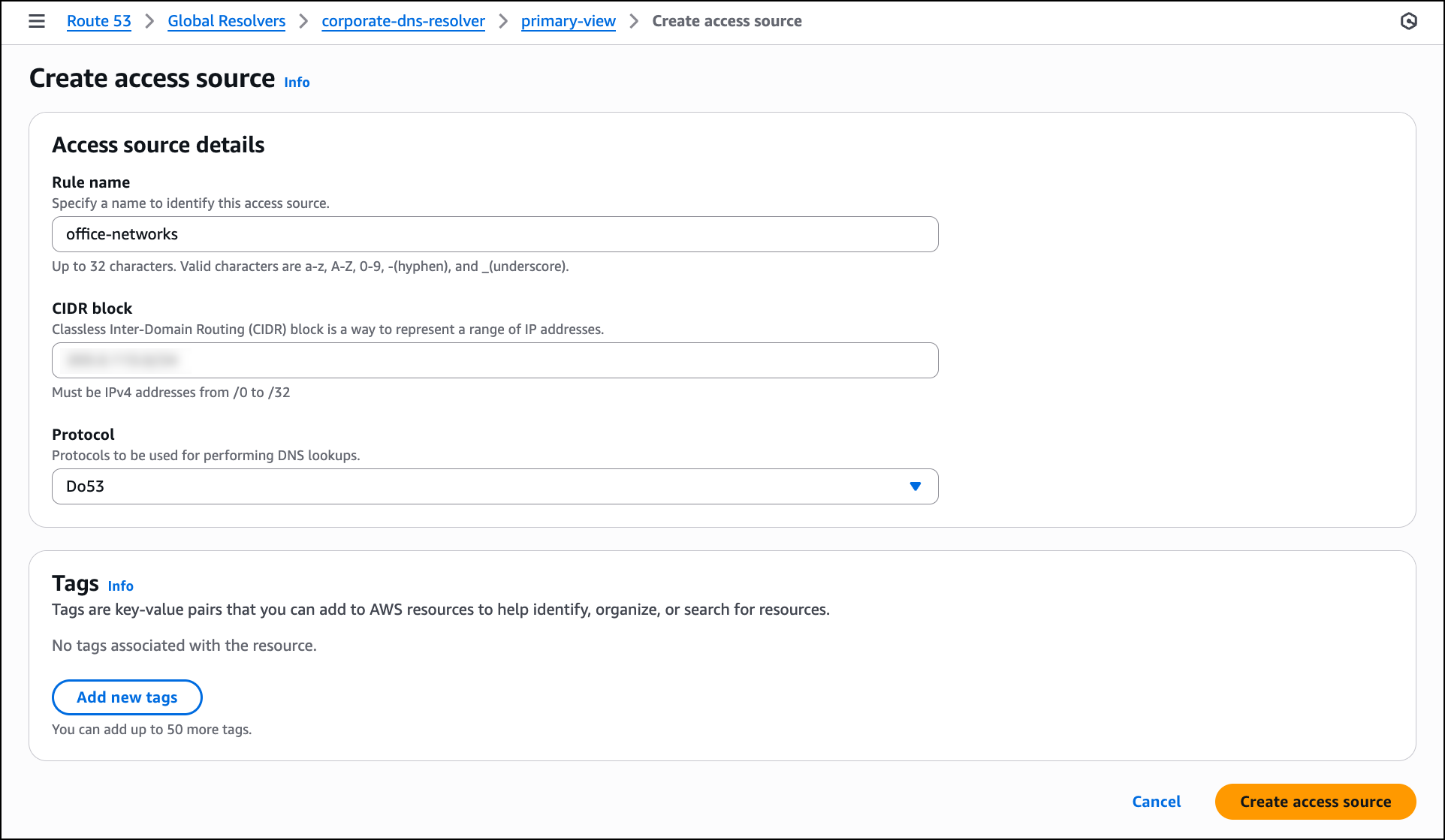
The next step is to configure access sources to specify which IP addresses or CIDR blocks are allowed to send DNS queries to the resolver. Navigate to the Access sources tab in the DNS view and then choose Create access source.

In the Access source details section, enter a Rule name such as office-networks to identify the access source. In the CIDR block field, enter the IP address range for your offices to allow queries from that network. For Protocol, select Do53 for standard DNS queries over UDP or choose DoH or DoT if you want to require encrypted DNS connections from clients. After configuring these settings, choose Create access source to allow the specified network to send DNS queries to the resolver.

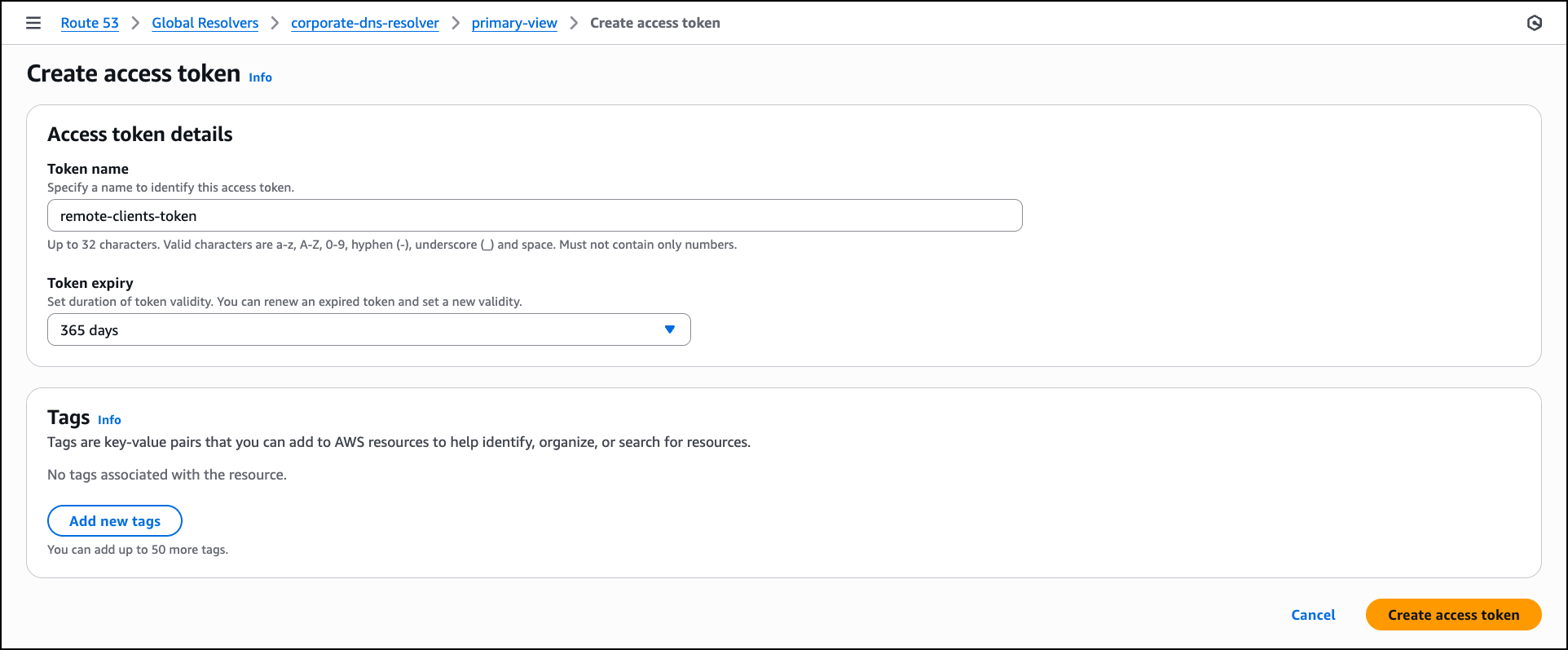
Next, navigate to the Access tokens tab in the DNS view to create token-based authentication for clients and choose Create access token. In the Access token details section, enter a Token name such as remote-clients-token. For Token expiry, select an expiration period from the dropdown based on your security requirements, such as 365 days for long-term client access, or choose a shorter duration like 30 days or 90 days for tighter access control. After configuring these settings, choose Create access token to generate the token, which clients can use to authenticate DoH and DoT connections to the resolver.

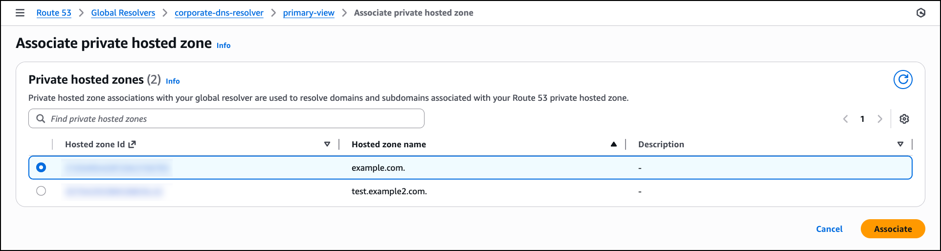
After the access token is created, navigate to the Private hosted zones tab in the DNS view to associate Route 53 private hosted zones with the DNS view so that the resolver can resolve queries for your private application domains. Choose Associate private hosted zone and in the Private hosted zones section, select a private hosted zone from the list that you want the resolver to handle. After selecting the zone, choose Associate to enable the resolver to respond to DNS queries for these private domains from your configured access sources.

With the DNS view configured, firewall rules created, access sources and tokens defined, and private hosted zones associated, the Route 53 Global Resolver setup is complete and ready to handle DNS queries from your configured clients.

After creating your Route 53 Global Resolver, you need to configure your DNS clients to send queries to the resolver’s anycast IP addresses. The configuration method depends on the access control you configured in your DNS view:

  • For IP-based access sources (CIDR blocks) – Configure your source clients to point DNS traffic to the Route 53 Global Resolver anycast IP addresses provided in the resolver details. Global Resolver will only allow access from allowlisted IPs that you have specified in your access sources. You can also associate the access sources to different DNS views to provide more granular DNS resolution views for different sets of IPs.
  • For access token–based authentication – Deploy the tokens on your clients to authenticate DoH and DoT connections with Route 53 Global Resolver. You must also configure your clients to point the DNS traffic to the Route 53 Global Resolver anycast IP addresses provided in the resolver details.

For detailed configuration instructions for your specific operating system and protocol, refer to the technical documentation.

Additional things to know
We’re renaming the existing Route 53 Resolver to Route 53 VPC Resolver. This naming change clarifies the architectural distinction between the two services. VPC Resolver operates Regionally within your VPCs to provide DNS resolution for resources in your Amazon VPC environment. VPC Resolver continues to support inbound and outbound resolver endpoints for hybrid DNS architectures within specific AWS Regions.

Route 53 Global Resolver complements Route 53 VPC Resolver by providing internet-reachable, global and private DNS resolution for on-premises and remote clients without requiring VPC deployment or private connections.

Existing VPC Resolver configurations remain unchanged and continue to function as configured. The renaming affects the service name in the AWS Management Console and documentation, but API operation names remain unchanged. If your architecture requires DNS resolution for resources within your VPCs, continue using VPC Resolver.

Join the preview
Route 53 Global Resolver reduces operational overhead by providing unified DNS resolution for public and private domains through a single managed service. The global anycast architecture improves reliability and reduces latency for distributed clients. Integrated security controls and centralized logging help organizations maintain consistent security policies across all locations while meeting compliance requirements.

To learn more about Amazon Route 53 Global Resolver, visit the Amazon Route 53 documentation.

You can start using Route 53 Global Resolver through the AWS Management Console in US East (N. Virginia), US East (Ohio), US West (N. California), US West (Oregon), Europe (Frankfurt), Europe (Ireland), Europe (London), Asia Pacific (Mumbai), Asia Pacific (Singapore), Asia Pacific (Tokyo), and Asia Pacific (Sydney) Regions.

— Esra

Secure Amazon Elastic VMware Service (Amazon EVS) with AWS Network Firewall

Post Syndicated from Sheng Chen original https://aws.amazon.com/blogs/architecture/secure-amazon-elastic-vmware-service-amazon-evs-with-aws-network-firewall/

Amazon Elastic VMware Service (Amazon EVS) helps organizations migrate, run, and scale VMware workloads natively on AWS. It delivers a VMware Cloud Foundation (VCF) environment that operates directly within your Amazon Virtual Private Cloud (Amazon VPC) on Amazon EC2 bare-metal instances. The solution helps customers accelerate cloud migrations and data center exits without needing to refactor existing applications.

For customers considering a hybrid cloud architecture, a unified network security solution is required to protect application traffic across Amazon EVS environments, Amazon VPCs, on-premises data centers and the internet. It also needs to provide a single point of control for firewall policy management, centralized logging, and monitoring to streamline network security operations.

AWS Network Firewall is a managed firewall and intrusion detection and prevention service (IDS/IPS) that can help address these requirements. Built on AWS managed infrastructure, it automatically scales with traffic demands while maintaining high availability and consistent performance. The service provides centralized policy management and traffic inspection across multiple VPCs and AWS accounts. Additionally, it provides comprehensive visibility and reporting through firewall log collections to Amazon Simple Storage Service (Amazon S3), Amazon CloudWatch Logs, or Amazon Data Firehose.

In this post, we demonstrate how to utilize AWS Network Firewall to secure an Amazon EVS environment, using a centralized inspection architecture across an EVS cluster, VPCs, on-premises data centers and the internet. We walk through the implementation steps to deploy this architecture using AWS Network Firewall and AWS Transit Gateway.

Architecture overview

AWS Network Firewall operates as a “bump-in-the-wire” solution, which transparently inspects and filters network traffic across Amazon VPCs. It is inserted directly into the traffic path by updating VPC or Transit Gateway route tables, allowing it to examine all packets without requiring any changes to the existing application flow patterns.

The following diagram depicts the architecture overview of our centralized inspection model using AWS Network Firewall.

Figure 1: Secure Amazon EVS with AWS Network Firewall using centralized inspection architecture

Figure 1: Secure Amazon EVS with AWS Network Firewall using centralized inspection architecture

The Amazon EVS environment is deployed directly within a customer VPC (i.e. EVS VPC), which consists of EVS VLAN subnets that form the underlay networks for VCF deployment. This infrastructure provides connectivity for NSX overlay networks, host management, vMotion, and vSANAmazon VPC Route Server enables dynamic routing between the underlay networks and overlay networks. For more information, see Concepts and components of Amazon EVS.

The architecture also includes a standard workload VPC (i.e. VPC01), and a Direct Connect Gateway connects to the on-premises data center via an AWS Direct Connect connection. We use a dedicated egress VPC with NAT gateways for centralized internet egress, and a separate ingress VPC with Application Load Balancers to terminate ingress web traffic and steer flows back to the target services.

With this architecture, the following traffic flow patterns can be inspected:

East-West Traffic:

  • Between EVS VPCs and Workload VPCs
  • Between Workload VPCs

North-South Traffic:

  • Between EVS/Workload VPCs and on-premises
  • Between EVS/Workload VPCs and internet
  • Between on-premises and internet

The centralized inspection architecture provides several benefits:

  • Single point of control for network security inspection across multiple VPCs
  • Enhanced rule enforcement across AWS infrastructure, on-premises resources, and the internet
  • Centralized logging and monitoring

For this demo we use the AWS Network Firewall native integration with AWS Transit Gateway capability to streamline firewall deployment and management. With a native firewall attachment, AWS automatically provisions and manages all the necessary VPC resources, reducing the operational overhead of managing subnets, route tables, and firewall endpoints within the inspection VPC.

Prerequisites

This post assumes familiarity with: AWS Command Line Interface (AWS CLI), Amazon VPC, Amazon EC2, NAT gateway, Application Load Balancer, Internet gateway, AWS Direct Connect, AWS Transit Gateway and the VMware VCF platform.

The following prerequisites are necessary to complete this solution.

  • An EVS VPC includes:
    • An Amazon EVS cluster (minimum 4x i4i nodes)
    • VPC CIDR: 10.0.0.0/16
    • NSX Segments CIDR: 192.168.0.0/19 (summarized)
    • A VPC Route Server deployed in the EVS VPC to receive NSX segment routes via BGP dynamic routing. Refer to the EVS User Guide for more details.
  • A Workload VPC (VPC01):
    • CIDR: 172.21.0.0/16
  • An Egress VPC:
    • CIDR: 172.23.0.0/16
    • 1x Internet Gateway
    • 1x NAT Gateway
  • An Ingress VPC:
    • CIDR: 172.24.0.0/16
    • 1x Internet Gateway
    • 1x Application Load Balancer
  • Optional: a Direct Connect Gateway:
    •  connecting to the on-premises environment (10.0.0.0/8)

Note: The CIDR blocks used in this example are for demo purposes only; change the address spaces to match your own networking environment. The design can also be scaled to include additional EVS environments and/or other VPCs based on workload needs.

Walkthrough

In this section, we walk through the implementation steps to deploy the centralized inspection architecture with AWS Network Firewall and AWS Transit Gateway. We focus on the overall network integration of the architecture without diving into the detailed configurations of AWS Network Firewall or Transit Gateway.

1. Create an AWS Transit Gateway

In the VPC console, create a Transit Gateway. Make sure to deselect the following options:

  • Default route table association
  • Default route table propagation

Create two empty transit gateway route tables and associate them with the Transit Gateway.

  • Pre-inspection route table: steers traffic into the AWS Network Firewall for centralized inspection
  • Post-inspection route table: returns traffic back to its original destination after inspection and is permitted by the AWS Network Firewall

2. Attach VPCs to the Transit Gateway

Attach all four VPCs (EVS, VPC01, Ingress, Egress) to the same Transit Gateway. The Direct Connect Gateway can also be attached to the Transit Gateway if AWS Network Firewall is needed to inspect traffic between the on-premises environment and AWS or the internet.

Figure 2: Attach VPCs to the Transit Gateway

Figure 2: Attach VPCs to the Transit Gateway

Associate all attachments to the pre-inspection Transit Gateway route table.

Figure 3: Associate VPC attachments to the pre-inspection route table

Figure 3: Associate VPC attachments to the pre-inspection route table

3. Create an AWS Network Firewall with Transit Gateway native integration

In the Network Firewall section of the VPC console, choose Create firewall.

At the Attachment type section, select Transit Gateway to enable native integration with the existing Transit Gateway.

Figure 4: Enable AWS Network Firewall native integration with Transit Gateway

Figure 4: Enable AWS Network Firewall native integration with Transit Gateway

At the Logging configuration, enable the following log types with CloudWatch log group as the log destination. Create a log group for each log type in the CloudWatch Console.

  • Alert: /anfw-centralized/anfw01/alert
  • Flow: /anfw-centralized/anfw01/flow

Create and associate an empty firewall policy to deploy the AWS Network Firewall instance. The firewall policy contains a list of rule groups that define how the firewall inspects and manages traffic. This empty firewall policy can be configured later.

With the Transit Gateway native integration enabled, a Transit Gateway attachment is automatically created for the AWS Network Firewall, with the resource type shown as Network Function. In addition, the Appliance Mode is automatically enabled for the firewall attachment to make sure the Transit Gateway continues to use the same Availability Zone (AZ) for the attachment over the lifetime of a flow.

Associate the firewall attachment to the post-inspection Transit Gateway route table.

Figure 5: AWS Network Firewall native attachment

Figure 5: AWS Network Firewall native attachment

4. Update Transit Gateway route tables

Update the pre-inspection Transit Gateway route table with a default route that points to the AWS Network Firewall attachment. This makes sure traffic that arrives to the Transit Gateway from all VPC attachments and the Direct Connect Gateway attachment is sent to the firewall for centralized inspection.

Figure 6: Transit Gateway pre-inspection route table

Figure 6: Transit Gateway pre-inspection route table

Add the following static routes to the post-inspection route table to direct return traffic back to each VPC and the Direct Connect Gateway accordingly.

Figure 7: Transit Gateway post-inspection route table

Figure 7: Transit Gateway post-inspection route table

5. Update VPC route tables

Finally, update route tables at each VPC as per the following table.

Make sure to add the following routes at the relevant VPC route tables:

  • EVS VPC and VPC01 have a default route (marked in blue) to steer all egress flows into AWS Network Firewall for centralized inspection.
  • Ingress VPC and Egress VPC have RFC-1918 routes (marked in green) to direct return traffic to the Transit Gateway.

Within the EVS VPC, notice the NSX segment routes are automatically propagated to the NSX uplink subnet route table and the private subnet route table via the VPC Route Server.

Figure 8: NSX uplink subnet route table within EVS VPC

Figure 8: NSX uplink subnet route table within EVS VPC

A centralized security inspection architecture has now been deployed for the EVS environment, using AWS Network Firewall with Transit Gateway native integration.

6. Testing

Egress inspection (FQDN filtering)

To test egress inspection from EVS VPC or VPC01 to the internet, create a stateful rule group for the firewall instance using FQDN filtering:

  • Rule group format: Domain list
  • Domain names: .google.com
  • Source IPs: 192.168.0.0/19, 172.21.0.0/16
  • Protocols: HTTP & HTTPS
  • Action: Allow

As expected, testing web access from a virtual machine (192.168.12.10) within the EVS environment to the allowed domain (i.e. google.com) is permitted by the AWS Network Firewall. However, access to unauthorized domain (i.e. facebook.com) is blocked at the firewall with an alert trigged, which can be verified at the CloudWatch log group at /aws/network-firewall/alert/.

Figure 9: Egress inspection from EVS to internet with FQDN filtering

Figure 9: Egress inspection from EVS to internet with FQDN filtering

Ingress inspection

Create another stateful rule group to allow Application Load Balancers deployed within the Ingress VPC to access a web server running in the EVS environment via HTTP protocol:

  • Rule group format: Standard stateful rule
  • Geographic IP Filtering: Disable Geographic IP filtering
  • Protocol: HTTP
  • Source: 172.24.0.0/16
  • Source Port: ANY
  • Destination: 192.168.12.10/32
  • Destination Port ANY
  • Traffic direction: Forward
  • Action: Alert

The CloudWatch firewall logs show an Application Load Balancer (172.24.6.45) from the Ingress VPC can establish HTTP connection to the EVS web server (192.168.12.10). Additionally, the Application Load Balancer has successfully registered the EVS web server as a remote IP target.

Figure 10: Ingress inspection from Ingress VPC to EVS

Figure 10: Ingress inspection from Ingress VPC to EVS

East-West inspection

For East-West inspection testing, update the previous stateful rule group to add a new rule to block ICMP traffic from VPC01 to the EVS VPC.

  • Rule group format: Standard stateful rule
  • Geographic IP Filtering: Disable Geographic IP filtering
  • Protocol: ICMP
  • Source: 172.21.0.0/16
  • Source Port: ANY
  • Destination: 192.168.0.0/19
  • Destination Port: ANY
  • Action: Drop

As a result, pings from an EC2 instance (172.21.128.4) from VPC01 to the EVS web server (192.168.12.10) are being dropped.

Figure 11: East-West Inspection from VPC01 to EVS

Figure 11: East-West Inspection from VPC01 to EVS

Conclusion

In this post, we demonstrated how to utilize AWS Network Firewall to secure Amazon EVS workloads and to provide centralized traffic inspection between Amazon EVS environments, Amazon VPCs, on-premises data centers, and the internet. We walked through the implementation steps for deploying the centralized inspection architecture using AWS Network Firewall and AWS Transit Gateway.

To learn more, review these resources:


About the authors

Introducing AWS RTB Fabric for real-time advertising technology workloads

Post Syndicated from Betty Zheng (郑予彬) original https://aws.amazon.com/blogs/aws/introducing-aws-rtb-fabric-for-real-time-advertising-technology-workloads/

Today, we’re announcing AWS RTB Fabric, a fully managed service purpose built for real-time bidding (RTB) advertising workloads. The service helps advertising technology (AdTech) companies seamlessly connect with their supply and demand partners, such as Amazon Ads, GumGum, Kargo, MobileFuse, Sovrn, TripleLift, Viant, Yieldmo and more, to run high-volume, latency-sensitive RTB workloads on Amazon Web Services (AWS) with consistent single-digit millisecond performance and up to 80% lower networking costs compared to standard networking costs.

AWS RTB Fabric provides a dedicated, high-performance network environment for RTB workloads and partner integrations without requiring colocated, on-premises infrastructure or upfront commitments. The following diagram shows the high-level architecture of RTB Fabric.

AWS RTB Fabric also includes modules, a capability that helps customers bring their own and partner applications securely into the compute environment used for real-time bidding. Modules support containerized applications and foundation models (FMs) that can enhance transaction efficiency and bidding effectiveness. At launch, AWS RTB Fabric includes modules for optimizing traffic management, improving bid efficiency, and increasing bid response rates, all running inline within the service for consistent low-latency execution.

The growth of programmatic advertising has created a need for low-latency, cost-efficient infrastructure to support RTB workloads. AdTech companies process millions of bid requests per second across publishers, supply-side platforms (SSPs), and demand-side platforms (DSPs). These workloads are highly sensitive to latency because most RTB auctions must complete within 200–300 milliseconds and require reliable, high-speed exchange of OpenRTB requests and responses among multiple partners. Many companies have addressed this by deploying infrastructure in colocation data centers near key partners, which reduces latency but adds operational complexity, long provisioning cycles, and high costs. Others have turned to cloud infrastructure to gain elasticity and scale, but they often face complex provisioning, partner-specific connectivity, and long-term commitments to achieve cost efficiency. These gaps add operational overhead and limit agility. AWS RTB Fabric solves these challenges by providing a managed private network built for RTB workloads that delivers consistent performance, simplifies partner onboarding, and achieves predictable cost efficiency without the burden of maintaining colocation or custom networking setups.

Key capabilities
AWS RTB Fabric introduces a managed foundation for running RTB workloads at scale. The service provides the following key capabilities:

  • Simplified connectivity to AdTech partners – When you register an RTB Fabric gateway, the service automatically generates secure endpoints that can be shared with selected partners. Using the AWS RTB Fabric API, you can create optimized, private connections to exchange RTB traffic securely across different environments. External Links are also available to connect with partners who aren’t using RTB Fabric, such as those operating on premises or in third-party cloud environments. This approach shortens integration time and simplifies collaboration among AdTech participants.
  • Dedicated network for low-latency advertising transactions – AWS RTB Fabric provides a managed, high-performance network layer optimized for OpenRTB communication. It connects AdTech participants such as SSPs, DSPs, and publishers through private, high-speed links that deliver consistent single-digit millisecond latency. The service automatically optimizes routing paths to maintain predictable performance and reduce networking costs, without requiring manual peering or configuration.
  • Pricing model aligned with RTB economics – AWS RTB Fabric uses a transaction-based pricing model designed to align with programmatic advertising economics. Customers are billed per billion transactions, providing predictable infrastructure costs that align with how advertising exchanges, SSPs, and DSPs operate.
  • Built-in traffic management modules – AWS RTB Fabric includes configurable modules that help AdTech workloads operate efficiently and reliably. Modules such as Rate Limiter, OpenRTB Filter, and Error Masking help you control request volume, validate message formats, and manage response handling directly in the network path. These modules execute inline within the AWS RTB Fabric environment, maintaining network-speed performance without adding application-level latency. All configurations are managed through the AWS RTB Fabric API, so you can define and update rules programmatically as your workloads scale.

Getting started
Today, you can start building with AWS RTB Fabric using the AWS Management Console, AWS Command Line Interface (AWS CLI), or infrastructure-as-code (IaC) tools such as AWS CloudFormation and Terraform.

The console provides a visual entry point to view and manage RTB gateways and links, as shown on the Dashboard of the AWS RTB Fabric console.

You can also use the AWS CLI to configure gateways, create links, and manage traffic programmatically. When I started building with AWS RTB Fabric, I used the AWS CLI to configure everything from gateway creation to link setup and traffic monitoring. The setup ran inside my Amazon Virtual Private Cloud (Amazon VPC) endpoint while AWS managed the low-latency infrastructure that connected workloads.

To begin, I created a requester gateway to send bid requests and a responder gateway to receive and process bid responses. These gateways act as secure communication points within the AWS RTB Fabric.

# Create a requester gateway with required parameters
aws rtbfabric create-requester-gateway \
  --description "My RTB requester gateway" \
  --vpc-id vpc-12345678 \
  --subnet-ids subnet-abc12345 subnet-def67890 \
  --security-group-ids sg-12345678 \
  --client-token "unique-client-token-123"
# Create a responder gateway with required parameters
aws rtbfabric create-responder-gateway \
  --description "My RTB responder gateway" \
  --vpc-id vpc-01f345ad6524a6d7 \
  --subnet-ids subnet-abc12345 subnet-def67890 \
  --security-group-ids sg-12345678 \
  --dns-name responder.example.com \
  --port 443 \
  --protocol HTTPS

After both gateways were active, I created a link from the requester to the responder to establish a private, low-latency communication path for OpenRTB traffic. The link handled routing and load balancing automatically.

# Requester account creating a link from requester gateway to a responder gateway
aws rtbfabric create-link \
  --gateway-id rtb-gw-requester123 \
  --peer-gateway-id rtb-gw-responder456 \
  --log-settings '{"applicationLogs:{"sampling":"errorLog":10.0,"filterLog":10.0}}'
# Responder account accepting a link from requester gateway to responder gateway
aws rtbfabric accept-link \
  --gateway-id rtb-gw-responder456 \
  --link-id link-reqtoresplink789 \
  --log-settings '{"applicationLogs:{"sampling":"errorLog":10.0,"filterLog":10.0}}'

I also connected with external partners using External Links, which extended my RTB workloads to on-premises or third-party environments while maintaining the same latency and security characteristics.

# Create an inbound external link endpoint for an external partner to send bid requests to
aws rtbfabric create-inbound-external-link \
  --gateway-id rtb-gw-responder456
# Create an outbound external link for sending bid requests to an external partner
aws rtbfabric create-outbound-external-link \
  --gateway-id rtb-gw-requester123 \
  --public-endpoint "https://my-external-partner-responder.com"

To manage traffic efficiently, I added modules directly into the data path. The Rate Limiter module controlled request volume, and the OpenRTB Filter validated message formats inline at network speed.

# Attach a rate limiting module
aws rtbfabric update-link-module-flow \
  --gateway-id rtb-gw-responder456 \
  --link-id link-toresponder789 \
  --modules '{"name":"RateLimiter":"moduleParameters":{"rateLimiter":{"tps":10000}}}'

Finally, I used Amazon CloudWatch to monitor throughput, latency, and module performance, and I exported logs to Amazon Simple Storage Service (Amazon S3) for auditing and optimization.

All configurations can also be automated with AWS CloudFormation or Terraform, allowing consistent, repeatable deployment across multiple environments. With RTB Fabric, I could focus on optimizing bidding logic while AWS maintained predictable, single-digit millisecond performance across my AdTech partners.

For more details, refer to the AWS RTB Fabric User Guide.

Now available
AWS RTB Fabric is available today in the following AWS Regions: US East (N. Virginia), US West (Oregon), Asia Pacific (Singapore), Asia Pacific (Tokyo), Europe (Frankfurt), and Europe (Ireland).

AWS RTB Fabric is continually evolving to address the changing needs of the AdTech industry. The service expands its capabilities to support secure integration of advanced applications and AI-driven optimizations in real-time bidding workflows that help customers simplify operations and improve performance on AWS. To learn more about AWS RTB Fabric, visit the AWS RTB Fabric page.

Betty

Build a multi-Region AWS PrivateLink backed service with seamless failover

Post Syndicated from Madhav Vishnubhatta original https://aws.amazon.com/blogs/architecture/build-a-multi-region-aws-privatelink-backed-service-with-seamless-failover/

Global Payments Inc. is a leading worldwide provider of payment technology and software solutions, headquartered in Atlanta, Georgia. The company processes more than 75 billion transactions annually, serving more than 5 million merchant locations and nearly 2,000 financial institutions globally. Through its merger with TSYS in 2019, Global Payments expanded its capabilities beyond merchant acquiring services to include issuer processing solutions.

The company’s services now encompass ecommerce and omnichannel payments, business management software, customer engagement tools, and cloud-based solutions. Their commitment to technological innovation and customer service has positioned them as one of the largest financial technology companies globally, consistently ranking among the Fortune 500.

This post demonstrates how the Issuer Solutions business of Global Payments, as a service provider, implemented cross-Region failover for an AWS PrivateLink backed service exposed to their customers. Their solution enables failover to a secondary Region without customer coordination, reducing Recovery Time Objective (RTO).

AWS PrivateLink involves two key roles: service providers and service consumers. Service providers build, own, and manage endpoint services. Service consumers create and manage Amazon Virtual Private Cloud (Amazon VPC) endpoints that connect their VPC to an Amazon VPC endpoint service privately, without exposing the traffic to the public internet. Enterprises often build services in multiple AWS Regions for resilience. This approach requires endpoint services in two Regions, with service consumers creating VPC endpoints for each service.

The architecture uses Amazon Route 53 to resolve the service’s Fully Qualified Domain Name (FQDN) to the active Region’s service. Amazon Application Recovery Controller (ARC) is used to initiate the failover.

Customer requirements

Issuer Solutions had the following requirements for this implementation:

  • The ability for consumers to access the service privately, without traversing the public internet
  • Resilience to degradation in a single Region by allowing failover to a secondary Region
  • Independent failover without customer coordination
  • Reliable and simple failover process

Solution overview

The following simplified architecture diagram illustrates the connectivity and failover mechanisms. The exact service implementation of Issuer Solutions is beyond this post’s scope. For simplicity, we represent the service as a Network Load Balancer backed by Amazon Elastic Compute Cloud (Amazon EC2) instances.

AWS Architecture diagram showing primary and secondary regions with Route53 Private Hosted Zones, VPC endpoints, and PrivateLink integration, illustrating the connectivity and failover mechanisms.

The solution consists of the following key components:

  • The service provider deploys identical services in two Regions. The service is represented in this simplified version with a Network Load Balancer backed by EC2 instances. Each Region is independent and therefore resilient against failures in the other Region.
  • Services are exposed through PrivateLink as VPC endpoint services in each Region, allowing client connections without needing NAT gateways or internet gateways and keeping the traffic within the customers’ own private IP space.
  • The service provider authorizes the consumer AWS account to find the services using the VPC endpoint service names.
  • The service consumer uses the VPC PrivateLink endpoint service names to create VPC endpoints with Elastic Network Interfaces (ENIs) in two Availability Zones in each Region. The consumer does this in both consumer Regions, and each consumer Region has two sets of VPC endpoints: one for the primary service of the provider and one for the secondary service.
  • The service consumer creates a Route 53 private hosted zone in each of the two Regions they use, each with two alias records, with a simple routing policy, pointing to the VPC endpoints’ FQDNs in their own Regions. These two alias records are primary.example.com and secondary.example.com.
  • The service provider creates a Route 53 ARC cluster with routing controls for the primary and secondary Regions.
  • The service provider creates a private hosted zone with a failover record set for a consumer specific CNAME like custC.service.p.com that resolves to primary.example.com and secondary.example.com. These records are associated with health checks that are associated with Route 53 ARC routing controls.

As shown in the architecture diagram, it is not necessary for the provider’s and consumer’s Regions to be the same because AWS supports creating VPC endpoints in a Region different to that of the VPC endpoint service itself. Refer to AWS PrivateLink now supports cross-region connectivity for more details.

How the DNS resolution works

Each consumer Region has two Route 53 private hosted zones involved in DNS resolution in this approach: the service provider’s hosted zone and the service consumer’s hosted zone. Both hosted zones are associated with the VPC used by the service consumer. Here is how the DNS resolution works:

  1. When a client in the consumer VPC wants to reach the service, it uses the FQDN custC.service.p.com.
  2. The hosted zone in the service provider’s account resolves custC.service.p.com to either primary.example.com or secondary.example.com depending on the status of the health checks controlled by ARC. For now, let’s assume this resolves to primary.example.com.
  3. Next, primary.example.com resolves to the VPC endpoint FQDN com.amazonaws.vpce.<primary-region>.vpce-svcabc123 due to the hosted zone in the service consumer.

At the time of failover, the service provider will update the ARC health checks to turn off the primary control and turn on the secondary routing control. This causes the service provider’s hosted zone to resolve custC.service.p.com to secondary.example.com, which in turn resolves to the VPC endpoint FQDN in the secondary Region due to the service consumer’s hosted zone.

Considerations

With this setup, the service provider can fail over when they need to without the service consumer having to manually make any changes. This is especially useful for services that have multiple service consumers. Additionally, service consumers can make changes to the VPC endpoint as they see fit. They only need to update the hosted zone they manage to make sure that primary.example.com and secondary.example.com point to the correct VPC endpoints.

We used ARC in this post because it offers a robust solution for cross-Region failover with built-in static stability. ARC also avoids single points of failure in the failover logic by distributing it across multiple Regions.

This setup demonstrates an active-passive configuration where traffic is routed to a single Region at a time using the Route 53 failover routing policy. For an active-active approach, you can adapt this setup by employing alternative Route 53 policies such as weighted or latency-based routing, as detailed in Active-active and active-passive failover.

Code sample

We have created a GitHub repository with Terraform code to demonstrate this solution. The repository has the steps to set it up and test it.

Conclusion

This implementation of cross-Region failover by Global Payments Issuer Solutions for their PrivateLink backed service demonstrates a robust and flexible approach to providing high availability and resilience. By using AWS services such as PrivateLink, Route 53, and Route 53 ARC, they have created a solution that meets their key requirements. This architecture not only benefits Global Payments by allowing them to manage failovers efficiently, but also provides advantages to their service consumers. Customers maintain control over their own infrastructure while benefiting from seamless service continuity. As cloud architectures continue to evolve, solutions like this showcase the power of combining various AWS services to create highly available and fault-tolerant systems that meet complex business needs.

Clone our GitHub repository now and deploy this solution in your own AWS environment to try out this approach to cross-Region failover. Contact your AWS representative today to begin your journey toward enhanced business continuity.


About the Authors

Designing centralized and distributed network connectivity patterns for Amazon OpenSearch Serverless

Post Syndicated from Ankush Goyal original https://aws.amazon.com/blogs/big-data/designing-centralized-and-distributed-network-connectivity-patterns-for-amazon-opensearch-serverless/

Amazon OpenSearch Serverless is a fully managed search and analytics service that automatically provisions and scales infrastructure to help you run search and analytics workloads without cluster management. With OpenSearch Serverless, you can quickly build search and analytics capabilities into your applications.

As organizations scale their use of OpenSearch Serverless, understanding network architecture and DNS management becomes increasingly important. Building upon the connectivity patterns discussed in our previous post Network connectivity patterns for Amazon OpenSearch Serverless, this post covers advanced deployment scenarios focused on centralized and distributed access patterns—specifically, how enterprises can simplify network connectivity across multiple AWS accounts and extend access to on-premises environments for their OpenSearch Serverless deployments.

We outline two key deployment patterns:

  • Pattern 1 – A centralized endpoint model where interface virtual private cloud (VPC) endpoints for OpenSearch Serverless are deployed in a shared services VPC, allowing spoke VPCs from other AWS accounts and on premises to access OpenSearch Serverless collections through these consolidated endpoints.
  • Pattern 2 – A distributed endpoint model where interface VPC endpoints are created in individual spoke VPCs, with multiple consumers (central account, on-premises networks, and other spoke accounts) accessing these endpoints through centralized DNS management. This approach provides direct connectivity within each spoke VPC while maintaining centralized DNS control and management across the organization.

Before diving into advanced deployment patterns, let’s review the DNS behavior of OpenSearch Serverless when accessed through an interface VPC endpoint (AWS PrivateLink). Understanding this foundational aspect can help clarify the connectivity patterns we explore in this post.

OpenSearch Serverless interface VPC endpoint DNS resolution

When creating an OpenSearch Serverless interface VPC endpoint, the service automatically provisions three private hosted zones: one visible private hosted zone us-east-1.aoss.amazonaws.com that handles domain resolution for the OpenSearch Serverless collection and dashboard, another visible private hosted zone us-east-1.opensearch.amazonaws.com that manages resolution for the OpenSearch UI (OpenSearch Dashboards), and one hidden internal private hosted zone that manages the final DNS resolution to private IP addresses.

Our objective in this post is to explore how the two private hosted zones for OpenSearch Serverless work together: the visible private hosted zone us-east-1.aoss.amazonaws.com for collections and dashboards, and the hidden private hosted zone for final DNS resolution to private IP addresses. We examine how these private hosted zones enable scalable DNS resolution in both centralized and distributed architectures. The following workflow diagram shows the DNS resolution flow for the us-east-1 AWS Region. The same pattern applies to other Regions, with the Region identifiers in the DNS records changing accordingly.

DNS Workflow Diagram AOSS

The workflow consists of the following steps:

  1. A user requests access to a collection URL (for example, abc.us-east-1.aoss.amazonaws.com).
  2. The DNS request is sent to the Amazon Route 53 Resolver, which checks the visible private hosted zone us-east-1.aoss.amazonaws.com and finds a CNAME record pointing to the endpoint-specific domain.
  3. The Route 53 Resolver uses the hidden internal private hosted zone to resolve this endpoint-specific domain to the VPC endpoint’s private IP address.
  4. Traffic is allowed only if it originates from the interface VPC endpoint approved by OpenSearch Serverless network policies.

Although this DNS Resolution Process provides flexible and secure private access, it becomes complex when you need connectivity from multiple VPCs, different AWS accounts, or on-premises networks. The following patterns address these challenges and outline strategies to simplify network access and DNS management for OpenSearch Serverless in such environments.

Pattern 1: Centralized interface VPC endpoint for OpenSearch Serverless

This pattern uses a centralized approach where a shared services AWS account with a shared services VPC hosts the OpenSearch Serverless interface VPC endpoint and OpenSearch Serverless collection. From there, other AWS accounts with Amazon VPCs (spoke VPCs) need to be able to access OpenSearch Serverless collections through this central endpoint. Organizations commonly implement this setup in hub-and-spoke network designs that connect their VPCs using either AWS Transit Gateway or AWS Cloud WAN. The following diagram illustrates this architecture.

AOSS Centralized Account

Challenge

When accessing from on-premises networks, both network access and DNS resolution for the OpenSearch Serverless interface VPC endpoint work successfully. However, although the endpoint is network-accessible from spoke VPCs (for example, through Transit Gateway or AWS Cloud WAN), DNS resolution from these VPCs fail.

This happens because OpenSearch Serverless creates and uses a private hosted zone us-east-1.aoss.amazonaws.com that is only associated with the VPC containing the endpoint, in this case, the Shared Services VPC. Simply sharing this private hosted zone with the spoke VPCs doesn’t solve the problem, because the wildcard CNAME record references a DNS name privatelink.c0X.sgw.iad.prod.aoss.searchservices.aws.dev. This DNS name can’t be resolved from other VPCs without additional configuration, because it belongs to a private hosted zone privatelink.c0X.sgw.iad.prod.aoss.searchservices.aws.dev that is only associated with the shared services VPC. This private hosted zone isn’t visible in your account and is controlled by AWS.

Solution: Use Amazon Route 53 Profiles for cross-VPC DNS resolution

To enable centralized DNS resolution, you can use Amazon Route 53 Profiles. With Route 53 Profiles, you can manage and apply DNS-related Amazon Route 53 configurations across multiple VPCs and AWS accounts. The following diagram illustrates the solution architecture.

AOSS Centralized Account Route53 Profile

The solution consists of the following steps:

  1. Create an OpenSearch Serverless interface VPC endpoint in the shared services VPC. This automatically creates and associates the following:
      1. Two default private hosted zones.
      2. One hidden private hosted zone with this VPC.
  2. Create a Route 53 Profile in the shared services account.
  3. Associate the interface VPC endpoint for OpenSearch Serverless with the Route 53 Profile.
    1. The Route 53 Profile automatically associates the hidden private hosted zone with the profile.
  4. Associate the private hosted zone us-east-1.aoss.amazonaws.com that was automatically created by OpenSearch Serverless with the Route 53 Profile.
  5. Share the Route 53 Profile with your other AWS accounts in your organization using AWS Resource Access Manager (AWS RAM).
  6. Associate the spoke VPCs (located in different accounts) with the Route 53 Profile.

If you have an existing Route 53 Profile in your shared services account that is already associated to spoke VPCs, you can simply associate the OpenSearch Serverless interface VPC endpoint and the private hosted zone us-east-1.aoss.amazonaws.com to this profile.

After completing these steps, the DNS resolution for the OpenSearch Serverless collection and dashboard endpoints works seamlessly from spoke VPCs associated with the Route 53 Profile. Clients in spoke VPCs can resolve and access OpenSearch Serverless collections and dashboards through the centralized VPC endpoint.

Pattern 2: Distributed interface VPC endpoint for OpenSearch Serverless

Each spoke VPC, residing in its respective AWS account, hosts its own OpenSearch Serverless collection and interface VPC endpoint. We now want to achieve the following:

  • Centralize DNS management in a shared services VPC to provide consistent resolution for OpenSearch Serverless collections deployed across multiple spoke accounts
  • Provide on-premises resources with DNS resolution capability for all OpenSearch Serverless collections across the organization through a Route 53 Resolver inbound endpoint in the shared services VPC

The following diagram illustrates this architecture.

AOSS Distributed

Challenge

Managing DNS resolution for OpenSearch Serverless collections and dashboards becomes complex in this distributed model because each interface VPC endpoint creates its own set of private hosted zones that are only associated with their respective VPCs. This creates a fragmented DNS landscape where the shared services VPC and on-premises networks need a consolidated way to resolve domains of OpenSearch Serverless collections and dashboards across multiple spoke accounts.

Solution: Use a self-managed private hosted zone in the shared services VPC for on-prem DNS resolution

To enable centralized DNS resolution for distributed endpoints, create a self-managed private hosted zone in the shared services account and associate it with the shared services VPC. Within this private hosted zone, you can create CNAME records that map each OpenSearch Serverless collection endpoint to its respective interface VPC endpoint DNS names in the spoke accounts. The following diagram illustrates this architecture.

AOSS Distributed Centralized DNS On Prem and VPC

Implementation consists of the following steps:

  1. Create a self-managed private hosted zone in the shared services account with the domain name us-east-1.aoss.amazonaws.com and associate it with the shared services VPC. For each OpenSearch Serverless collection, create a CNAME record that points to the Regional DNS name of its corresponding interface VPC endpoint.

This configuration enables both on-premises resources and resources in the shared services VPC to resolve OpenSearch Serverless endpoints that are in the spoke accounts.

After you complete these steps, each OpenSearch Serverless interface VPC endpoint remains within its original AWS account, maintaining security boundaries and account-level autonomy. On-premises systems can access OpenSearch Serverless collections and dashboards using original collection DNS names (for example, {collection-name}.us-east-1.aoss.amazonaws.com) through DNS resolution provided by the private hosted zone in the shared services VPC.

Conclusion

As organizations scale their adoption of OpenSearch Serverless, establishing secure and centralized network access becomes increasingly important. In this post, we explored two architectural patterns specifically around DNS management:

  • Centralized endpoint model – This pattern is ideal when a shared services account manages the OpenSearch Serverless interface VPC endpoints, allowing multiple spoke accounts to access OpenSearch Serverless collections and dashboards through a centralized set of network resources.
  • Distributed endpoint model with centralized DNS – This pattern is suitable for organizations that require account-level autonomy, where each AWS account manages its own OpenSearch Serverless interface VPC endpoints, while DNS resolution is centralized through a shared self-managed private hosted zone in a shared services account.

By understanding the DNS architecture of OpenSearch Serverless and using services like Route 53 Profiles and AWS RAM, organizations can build secure and robust access patterns that align with their organizational structure and needs.


About the Authors

Ankush GoyalAnkush Goyal is a Enterprise Support Lead in AWS Enterprise Support who helps customers streamline their cloud operations on AWS. He is a results-driven IT professional with over 20 years of experience.

Anvesh KogantiAnvesh Koganti is a Solutions Architect at AWS specializing in Networking. He focuses on helping customers build networking architectures for highly scalable and resilient AWS environments. Outside of work, Anvesh is passionate about consumer technology and enjoys listening to podcasts on tech and business. When disconnecting from the digital world, Anvesh spends time outdoors hiking and biking.

Salman AhmedSalman Ahmed is a Senior Technical Account Manager in AWS Enterprise Support. He specializes in guiding customers through the design, implementation, and support of AWS solutions. Combining his networking expertise with a drive to explore new technologies, he helps organizations successfully navigate their cloud journey. Outside of work, he enjoys photography, traveling, and watching his favorite sports teams.

Reduce your operational overhead today with Amazon CloudFront SaaS Manager

Post Syndicated from Veliswa Boya original https://aws.amazon.com/blogs/aws/reduce-your-operational-overhead-today-with-amazon-cloudfront-saas-manager/

Today, I’m happy to announce the general availability of Amazon CloudFront SaaS Manager, a new feature that helps software-as-a-service (SaaS) providers, web development platform providers, and companies with multiple brands and websites efficiently manage delivery across multiple domains. Customers already use CloudFront to securely deliver content with low latency and high transfer speeds. CloudFront SaaS Manager addresses a critical challenge these organizations face: managing tenant websites at scale, each requiring TLS certificates, distributed denial-of-service (DDoS) protection, and performance monitoring.

With CloudFront Saas Manager, web development platform providers and enterprise SaaS providers who manage a large number of domains will use simple APIs and reusable configurations that use CloudFront edge locations worldwide, AWS WAF, and AWS Certificate Manager. CloudFront SaaS Manager can dramatically reduce operational complexity while providing high-performance content delivery and enterprise-grade security for every customer domain.

How it works
In CloudFront, you can use multi-tenant SaaS deployments, a strategy where a single CloudFront distribution serves content for multiple distinct tenants (users or organizations). CloudFront SaaS Manager uses a new template-based distribution model called a multi-tenant distribution to serve content across multiple domains while sharing configuration and infrastructure. However, if supporting single websites or application, a standard distribution would be better or recommended.

A template distribution defines the base configuration that will be used across domains such as origin configurations, cache behaviors, and security settings. Each template distribution has a distribution tenant to represent domain-specific origin paths or origin domain names including web access control list (ACL) overrides and custom TLS certificates.

Optionally, multiple distribution tenants can use the same connection group that provides the CloudFront routing endpoint that serves content to viewers. DNS records point to the CloudFront endpoint of the connection group using a Canonical Name Record (CNAME).

To learn more, visit Understand how multi-tenant distributions work in the Amazon CloudFront Developer Guide.

CloudFront SaaS Manager in action
I’d like to give you an example to help you understand the capabilities of CloudFront SaaS Manager. You have a company called MyStore, a popular e-commerce platform that helps your customer easily set up and manage an online store. MyStore’s tenants already enjoy outstanding customer service, security, reliability, and ease-of-use with little setup required to get a store up and running, resulting in 99.95 percent uptime for the last 12 months.

Customers of MyStore are unevenly distributed across three different pricing tiers: Bronze, Silver, and Gold, and each customer is assigned a persistent mystore.app subdomain. You can apply these tiers to different customer segments, customized settings, and operational Regions. For example, you can add AWS WAF service in the Gold tier as an advanced feature. In this example, MyStore has decided not to maintain their own web servers to handle TLS connections and security for a growing number of applications hosted on their platform. They are evaluating CloudFront to see if that will help them reduce operational overhead.

Let’s find how as MyStore you configure your customer’s websites distributed in multiple tiers with the CloudFront SaaS Manager. To get started, you can create a multi-tenant distribution that acts as a template corresponding to each of the three pricing tiers the MyStore offers: Bronze, Sliver, and Gold shown in Multi-tenant distribution under the SaaS menu on the Amazon CloudFront console.

To create a multi-tenant distribution, choose Create distribution and select Multi-tenant architecture if you have multiple websites or applications that will share the same configuration. Follow the steps to provide basic details such as a name for your distribution, tags, and wildcard certificate, specify origin type and location for your content such as a website or app, and enable security protections with AWS WAF web ACL feature.

When the multi-tenant distribution is created successfully, you can create a distribution tenant by choosing Create tenant in the Distribution tenants menu in the left navigation pane. You can create a distribution tenant to add your active customer to be associated with the Bronze tier.

Each tenant can be associated with up to one multi-tenant distribution. You can add one or more domains of your customers to a distribution tenant and assign custom parameter values such as origin domains and origin paths. A distribution tenant can inherit the TLS certificate and security configuration of its associated multi-tenant distribution. You can also attach a new certificate specifically for the tenant, or you can override the tenant security configuration.

When the distribution tenant is created successfully, you can finalize this step by updating a DNS record to route traffic to the domain in this distribution tenant and creating a CNAME pointed to the CloudFront application endpoint. To learn more, visit Create a distribution in the Amazon CloudFront Developer Guide.

Now you can see all customers in each distribution tenant to associate multi-tenant distributions.

By increasing customers’ business needs, you can upgrade your customers from Bronze to Silver tiers by moving those distribution tenants to a proper multi-tenant distribution.

During the monthly maintenance process, we identify domains associated with inactive customer accounts that can be safely decommissioned. If you’ve decided to deprecate the Bronze tier and migrate all customers who are currently in the Bronze tier to the Silver tier, then you can delete a multi-tenant distribution to associate the Bronze tier. To learn more, visit Update a distribution or Distribution tenant customizations in the Amazon CloudFront Developer Guide.

By default, your AWS account has one connection group that handles all your CloudFront traffic. You can enable Connection group in the Settings menu in the left navigation pane to create additional connection groups, giving you more control over traffic management and tenant isolation.

To learn more, visit Create custom connection group in the Amazon CloudFront Developer Guide.

Now available
Amazon CloudFront SaaS Manager is available today. To learn about, visit CloudFront SaaS Manager product page and documentation page. To learn about SaaS on AWS, visit AWS SaaS Factory.

Give CloudFront SaaS Manager a try in the CloudFront console today and send feedback to AWS re:Post for Amazon CloudFront or through your usual AWS Support contacts.

Veliswa.
_______________________________________________

How is the News Blog doing? Take this 1 minute survey!

(This survey is hosted by an external company. AWS handles your information as described in the AWS Privacy Notice. AWS will own the data gathered via this survey and will not share the information collected with survey respondents.)

Amazon API Gateway now supports dual-stack (IPv4 and IPv6) endpoints

Post Syndicated from Betty Zheng (郑予彬) original https://aws.amazon.com/blogs/aws/amazon-api-gateway-now-supports-dual-stack-ipv4-and-ipv6-endpoints/

Today, we are launching IPv6 support for Amazon API Gateway across all endpoint types, custom domains, and management APIs, in all commercial and AWS GovCloud (US) Regions. You can now configure REST, HTTP, and WebSocket APIs, and custom domains, to accept calls from IPv6 clients alongside the existing IPv4 support. You can also call API Gateway management APIs from dual-stack (IPv6 and IPv4) clients. As organizations globally confront growing IPv4 address scarcity and increasing costs, implementing IPv6 becomes critical for future-proofing network infrastructure. This dual-stack approach helps organizations maintain future network compatibility and expand global reach. To learn more about dualstack in the Amazon Web Services (AWS) environment, see the IPv6 on AWS documentation.

Creating new dual-stack resources

This post focuses on two ways to create an API or a domain name with a dualstack IP address type: AWS Management Console and AWS Cloud Development Kit (CDK).

AWS Console

When creating a new API or domain name in the console, select IPv4 only or dualstack (IPv4 and IPv6) for the IP address type.

As shown in the following image, you can select the dualstack option when creating a new REST API.
For custom domain names, you can similarly configure dualstack as shown in the next image.

If you need to revert to IPv4-only for any reason, you can modify the IP address type setting, with no need to redeploy your API for the update to take effect.

REST APIs of all endpoint types (EDGE, REGIONAL and PRIVATE) support dualstack. Private REST APIs only support dualstack configuration.

AWS CDK

With AWS CDK, start by configuring a dual-stack REST API and domain name.

const api = new apigateway.RestApi(this, "Api", {
  restApiName: "MyDualStackAPI",
  endpointConfiguration: {ipAddressType: "dualstack"}
});

const domain_name = new apigateway.DomainName(this, "DomainName", {
  regionalCertificateArn: 'arn:aws:acm:us-east-1:111122223333:certificate/a1b2c3d4-5678-90ab',
  domainName: 'dualstack.example.com',
  endpointConfiguration: {
    types: ['Regional'],
    ipAddressType: 'dualstack'
  },
  securityPolicy: 'TLS_1_2'
});

const basepathmapping = new apigateway.BasePathMapping(this, "BasePathMapping", {
  domainName: domain_name,
  restApi: api
});

IPv6 Source IP and authorization

When your API begins receiving IPv6 traffic, client source IPs will be in IPv6 format. If you use resource policies, Lambda authorizers, or AWS Identity and Access Management (IAM) policies that reference source IP addresses, make sure they’re updated to accommodate IPv6 address formats.

For example, to permit traffic from a specific IPv6 range in a resource policy.

{
  "Version": "2012-10-17",
  "Statement": [
    {
      "Effect": "Allow",
      "Principal": "*",
      "Action": "execute-api:Invoke",
      "Resource": "execute-api:stage-name/*",
      "Condition": {
        "IpAddress": {
          "aws:SourceIp": [
            "192.0.2.0/24",
            "2001:db8:1234::/48"
          ]
        }
      }
    }
  ]
}

Summary

API Gateway dual-stack support helps manage IPv4 address scarcity and costs, comply with government and industry mandates, and prepare for the future of networking. The dualstack implementation provides a smooth transition path by supporting both IPv4 and IPv6 clients simultaneously.

To get started with API Gateway dual-stack support, visit the Amazon API Gateway documentation. You can configure dualstack for new APIs or update existing APIs with minimal configuration changes.

Betty

Special thanks to Ellie Frank (elliesf), Anjali Gola (anjaligl), and Pranika Kakkar (pranika) for providing resources, answering questions, and offering valuable feedback during the writing process. This blog post was made possible through the collaborative support of the service and product management teams.


How is the News Blog doing? Take this 1 minute survey!

(This survey is hosted by an external company. AWS handles your information as described in the AWS Privacy Notice. AWS will own the data gathered via this survey and will not share the information collected with survey respondents.)

New physical AWS Data Transfer Terminals let you upload to the cloud faster

Post Syndicated from Channy Yun (윤석찬) original https://aws.amazon.com/blogs/aws/new-physical-aws-data-transfer-terminals-let-you-upload-to-the-cloud-faster/

Today, we’re announcing the general availability of AWS Data Transfer Terminal, a secure physical location where you can bring your storage devices and upload data faster to the AWS Cloud.

The first Data Transfer Terminals are located in Los Angeles and New York, with plans to add more locations globally. You can reserve a time slot to visit your nearest location and upload data rapidly and securely to any AWS public endpoints, such as Amazon Simple Storage Service (Amazon S3), Amazon Elastic File System (Amazon EFS), or others, using a high throughput connection. Using AWS Data Transfer Terminal, you can significantly reduce the time of ingesting data with high throughput connectivity in the location near by you. You can upload large datasets from fleets of vehicles operating and collecting data in metro areas for training machine learning (ML) models, digital audio and video files from content creators for media processing workloads, and mapping or imagery data from local government organizations for geographic analysis.

After the data is uploaded to AWS, you can use the extensive suite of AWS services to generate value from your data and accelerate innovation. You can also bring your AWS Snowball devices to the location for upload and retain the device for continued use and not rely on traditional shipping methods.

Getting started with AWS Data Transfer Terminal
You can find the availability of a location in the AWS Management Console and reserve the date and time to visit. Then, you can visit the location, make a connection between your storage device and S3 bucket, initiate the transfer of your data, and validate that your transfer is complete.

Go to the AWS Data Transfer Terminal console, then choose Get started.

Choose Create Transfer Team and make a team by adding the team’s name and description with agreement of service terms and conditions. You can add your team members for personal or group reservation in the team setting.

To reserve your time and location, choose Create Reservation.

In the first step, choose your team, a process owner to manage your reservation, and team members to visit the location for the data transferring job. Now, you can choose a location of Data Transfer Terminal facility and set your preferred visiting time. You’ll pay for the space reservation at an hourly rate for your reserved time.

To secure your reservation, choose Next and Create after reviewing the reservation details.

After your reservation is requested, you can find your upcoming reservations in the team page. You can check the reservation status or cancel your reservation.

On your reserved date and time, visit the location and confirm access with the building reception. You’re escorted by building staff to the floor and your reserved room of the Data Transfer Terminal location.

Don’t be surprised if there are no AWS signs in the building or room. This is for security reasons to keep your work location as secret as possible.

Visiting a pilot Terminal
Instead of me visiting a Data Transfer Terminal location where I live in Seoul, Jeff Barr visited a pilot location near him in Seattle to test uploading data as my team member.

The room is equipped with a patch panel, fiber optic cable, and a personal computer. The patch panel is installed inside a wall mount rack or small floor rack to allow additional space on the desk table. With the personal computer, you can see how to remote access to the server during data transfer process.

Here is Jeff’s feedback about visiting and working at the pilot facility.

When I arrived at the building, I was kindly escorted in and able to work easily using the instructions provided at the time of reservation. This location provides me with direct access to AWS global network infrastructure in a secure and on-demand format. I am excited to see how customers use AWS Data Transfer Terminal to more quickly get data into the cloud where they can more rapidly innovate and build on AWS.

Thanks, Jeff, for visiting the facility and doing the uploading job in my place!

Now available
AWS Data Transfer Terminal is now available today in Los Angeles and New York, with plans to add more locations globally.

You’ll be charged for on-demand use per hour for each location. There will be no per GB charge for the data transfer if you upload data into AWS Regions in the same continent of your location. To learn more, visit the Data Transfer Terminal pricing page.

Give AWS Data Transfer Terminal a try in the AWS Management Console. To learn more, refer to the Data Transfer Terminal page and send feedback through your usual AWS Support contacts.

Channy

Introducing Amazon CloudFront VPC origins: Enhanced security and streamlined operations for your applications

Post Syndicated from Matheus Guimaraes original https://aws.amazon.com/blogs/aws/introducing-amazon-cloudfront-vpc-origins-enhanced-security-and-streamlined-operations-for-your-applications/

I’m happy to introduce the release of Amazon CloudFront Virtual Private Cloud (VPC) origins, a new feature that enables content delivery from applications hosted in private subnets within their Amazon Virtual Private Cloud (Amazon VPC). This makes it easy to secure web applications, allowing you to focus on growing your businesses while improving security and maintaining high-performance and global scalability with CloudFront.

Customers serving content from Amazon Simple Storage Solution (Amazon S3), AWS Elemental Services and AWS Lambda Function URLs can use Origin Access Control as a managed solution to secure their origins, and make CloudFront the single front-door to your application. However, this was more difficult to achieve for applications that are hosted on Amazon Elastic Compute Cloud (Amazon EC2) or using load balancers, because you had to create your own solution to achieve the same result. You would have to use a combination of methods such as using access control lists (ACLs), managing firewall rules, or using logic such as header validation and a few other techniques to ensure that the endpoint remained exclusive to CloudFront.

CloudFront VPC origins removes the need for this kind of undifferentiated work by offering a managed solution that can be used to point CloudFront distributions directly to Application Load Balancers (ALBs), Network Load Balancers (NLBs), or EC2 instances inside your private subnets. This ensures that CloudFront becomes the sole ingress point for those resources with minimum configuration effort, providing you with improved performance and a cost-saving opportunity because it also eliminates the need for public IP addresses.

Configuring a CloudFront VPC origin
CloudFront VPC origins is available at no additional cost, making it an accessible option for all AWS customers. It can be integrated with new or existing CloudFront distributions using the Amazon CloudFront console or the AWS Command Line Interface (AWS CLI).

Imagine that you have an application hosted privately on an AWS Fargate for Amazon ECS fronted through an ALB. Let’s create a CloudFront distribution that uses the ALB directly inside the private subnet.

Start by navigating to the CloudFront console and select the new menu option: VPC origins.

vpc origins page

Creating a new VPC origin is straightforward. You only need to select from a few options. In the Origin ARN, you can search for available resources that are hosted in private subnets or enter it directly. You select the resources that you want, choose a friendly name for your VPC origin alongside some security options, and then confirm. Please note that, at launch, the VPC origin resource must be in the same AWS Account as the CloudFront distribution, although support for resources across all accounts is coming soon.

creating a vpc origin

After the creation process is complete, your VPC origin will be deployed and ready to go! You can check its status on the VPC origins page.

With this, we have created a CloudFront distribution that serves content directly from a resource hosted on a private subnet in a few clicks! After your VPC origin is created, you can navigate to your Distribution window, and add the VPC origin to your Distribution by either selecting the ARN from the dropdown or copy-pasting the ARN manually.

Remember, though, that it’s important to still continue to layer your application’s security by using services such as AWS Web Application Firewall (WAF) to protect from web exploits, or AWS Shield for managed DDos protection, and other services to achieve a full-spectrum protection.

Conclusion
CloudFront VPC Origins offers a new way for organizations to deliver secure, high-performance applications by enabling CloudFront distributions to serve content directly from resources hosted within private subnets. This reduces the complexity and cost of maintaining public-facing origins while ensuring that your application remains secure.

To learn more, see the getting started guide.

Matheus Guimaraes | @codingmatheus

Amazon CloudFront now accepts your applications’ gRPC calls

Post Syndicated from Sébastien Stormacq original https://aws.amazon.com/blogs/aws/amazon-cloudfront-now-accepts-your-applications-grpc-calls/

Starting today, you can deploy Amazon CloudFront, our global content delivery network (CDN), in front of your gRPC API endpoints.

gRPC is a modern, efficient, and language-agnostic framework for building APIs. It uses Protocol Buffers (protobuf) as its interface definition language (IDL), which enable you to define services and message types in a platform-independent manner. With gRPC, communication between services is achieved through lightweight and high-performance remote procedure calls (RPCs) over HTTP/2. This promotes efficient and low-latency communication across services, making it ideal for microservices architectures.

gRPC offers features such as bidirectional streaming, flow control, and automatic code generation for a variety of programming languages. It’s well-suited for scenarios in which you require high performance, efficient communication, and real-time data streaming. If your application needs to handle a large amount of data or requires low-latency communication between client and server, gRPC can be a good choice. However, gRPC might be more challenging to learn compared to REST. For example, gRPC relies on the protobuf serialization format, which requires developers to define their data structures and service methods in .proto files.

I see two benefits of deploying CloudFront in front of your gRPC API endpoints.

First, it allows the reduction of latency between the client application and your API implementation. CloudFront offers a global network of over 600+ edge locations with intelligent routing to the closest edge. Edge locations provide TLS termination and optional caching for your static content. CloudFront transfers client application requests to your gRPC origin through the fully managed, low-latency, and high-bandwidth private AWS network.

Secondly, your applications benefit from additional security services deployed on edge locations, such as traffic encryption, the validation of the HTTP headers through AWS Web Application Firewall, and AWS Shield Standard protection against distributed denial of service (DDoS) attacks.

Let’s see it in action
To start this demo, I use the gRPC route-guide demo from the official gRPC code repository. I deploy this example application in a container for ease of deployment (but any other deployment option is supported too).

I use this Dockerfile

FROM python:3.7
RUN pip install protobuf grpcio
COPY ./grpc/examples/python/route_guide .
CMD python route_guide_server.py
EXPOSE 50051

I also use the AWS Copilot command line to deploy my container on Amazon Elastic Container Service (Amazon ECS). The Copilot command prompts me to collect the information it requires to build and deploy the container. Then, it creates the ECS cluster, the ECS service, and the ECS task automatically. It also creates a TLS certificate and the load balancer for me. I test the client application by modifying line 122 to use the DNS name of the load balancer listener endpoint. I also change the client application code to use grpc.secure_channel instead of grpc.insecure_channel because the load balancer provides the application with an HTTPS endpoint.

gRPC client application demo - source code with ALB

When I’m confident my API is correctly deployed and working, I proceed and configure CloudFront.

First, in the CloudFront section of the AWS Management Console, I select Create distribution.

Under Origin, I enter my gRPC endpoint DNS name as Origin domain. I enable HTTPS only as Protocol and leave the HTTPS port as is (443). Then I choose a Name for the distribution.

CloudFront - Add origin and name

Under Viewer, I select HTTPS only as Viewer protocol policy. Then, I select GET, HEAD, OPTIONS, PUT, POST, PATCH, DELETE as Allowed HTTP methods. I select Enable for Allow gRPC requests over HTTP/2.

CloudFront - Viewer Policy

Under Cache key and origin requests, I select AllViewer as Origin request policy.

The default cache policy is CacheOptimized, but gRPC isn’t cacheable API traffic. Therefore, I select CachingDisabled as Cache policy.

CloudFront - Cache policy

AWS WAF helps protect you against common web exploits and bots that can affect availability, compromise security, or consume excessive resources. For gRPC traffic, AWS WAF can inspect the HTTP headers of the request and enforce access control. It doesn’t inspect the request body in protobuf format.

For this demo, I choose to not use AWS WAF. Under Web Application Firewall (WAF), I select Do not enable security protections.

CloudFront - Security

I also keep all the other options with their default value. HTTP/2 support is selected by default. Do not disable it because it is required for gRPC.

Finally, I select Create distribution.

CloudFront - Create distribution

There is only one switch to enable gRPC on top of the usual setup. When turned on, with HTTP/2 and HTTP POST enabled, CloudFront detects gRPC client traffic and forwards it to your gRPC origin.

After a few minutes, the distribution is ready. I copy and paste the endpoint URL of the CloudFront distribution, and I change the client-side app to make it point to CloudFront instead of the previously created load balancer.

gRPC client application demo - source code

I test the application again, and it works.

gRPC client application demo - execution

Pricing and Availability
gRPC origins are available on all the more than 600 CloudFront edge locations at no additional cost. The usual requests and data transfer fees apply.

Go and point your CloudFront origin to a gRPC endpoint today.

— seb

AWS and Multicloud: Existing capabilities & continued enhancements

Post Syndicated from Jeff Barr original https://aws.amazon.com/blogs/aws/aws-and-multicloud-existing-capabilities-continued-enhancements/

When I speak to large-scale AWS customers about their challenges and concerns, the conversation often turns to the topic of multicloud. Whether by intent or by accident, these customers sometimes choose to make use of services from more than one cloud provider, sometimes in conjunction with applications or services that are still hosted on-premises. In some cases they made early, bottom-up choices at the team and division level, choosing cloud offerings from multiple vendors in the absence of a top-down mandate. In others, they acquired or merged with another organization and discovered a similar multi-vendor situation.

Regardless of the path, these customers tell me that they want to simplify and centralize their oversight and management of this diverse portfolio of cloud and on-premises resources. It is sometimes the case that the “multi” situation is time-bound, with a plan in place to ultimately consolidate operations in one place. It is also sometimes the case that the customer plans to retain their diverse portfolio.

AWS and multicloud
Our goal with AWS is to make you successful no matter what architectural choices you have made. In this post I want to outline our approach, share some capabilities that our customers have been using over the years, and provide you with an update on some of the more recent service announcements and content that we have created to give you guidance that will help you to succeed.

Our approach is to extend existing AWS operational and management capabilities to work in multicloud and hybrid environments. Because we extend existing capabilities, your investment in training, development, scripting, and runbooks is preserved, and actually becomes even more worthwhile since it applies to your other (non-AWS) resources. For example, you can use the same service (AWS Systems Manager) to patch and update Amazon Elastic Compute Cloud (Amazon EC2) instances, servers running on-premises, and servers provided by other cloud providers. Similarly, you can use Amazon CloudWatch to monitor applications, compute resources, and other cloud resources in all of those environments. These are two examples of how we are putting our approach into practice for you.

The AWS Solutions for Hybrid and Multicloud page contains additional examples of our extension-based approach to adding new capabilities, along some success stories from customers who have put the capabilities to use including Phillips 66 and Deutsche Börse.

Whether you choose to operate entirely on AWS or in multicloud and hybrid environments, one of the primary reasons to adopt AWS is the broad choice of services we offer, enabling you to innovate, build, deploy, and monitor your workloads. Just as we recently launched free data transfer out to the internet (DTO) when you want to move outside of AWS, we are committed to helping you be successful regardless of your approach.

Now that I have explained our approach and highlighted some of the principal multicloud service offerings, let’s take a look at a few of the newest multicloud and hybrid capabilities.

Multicloud launches
Since the beginning of 2023 we have launched eighteen new multicloud capabilities to existing AWS services, including 15 for data & analytics, 1 for security, and 2 for identity. Many of these launches add to the existing multicloud capabilities of the respective services:

AWS DataSync – This service transfers data between storage services. In addition to existing support for Google Cloud Storage, Azure Files, and Azure Blob Storage, we added support for five additional cloud service providers and storage services including Oracle Cloud Storage and DigitalOcean Spaces (full list). To learn more about this service, read What is AWS DataSync. To get started, I create a source location:

AWS Glue – This data integration service helps you to discover, prepare, and integrate all of your data at any scale. You can use it to connect to more than 80 different data sources, including cloud databases and analytics services. In October 2023, we introduced additional new connectors that allow you to move data bidirectionally between Amazon Simple Storage Service (Amazon S3), and either Azure Blob Storage or Azure Data Lake Storage (full list). We also launched six database connectors for AWS Glue for Apache Spark, including Teradata, SAP HANA, Azure SQL, Azure Cosmos DB, Vertica, and MongoDB (full list). To learn more about AWS Glue, read What is AWS Glue. I create a visual job flow to get started:

Amazon Athena – This serverless analytics service lets you use interactive SQL queries to analyze petabyte-scale data where it lives (more than 25 external data sources, including other cloud data stores), without copying or transforming it. Last year we added a new data source connector that allows you to query data in Google Cloud Storage. To learn more about Amazon Athena, read What is Amazon Athena.

Amazon AppFlow – You can take advantage of data and analytics in Google BigQuery using a connector available in Amazon AppFlow. To get started with Amazon AppFlow I create a flow and configure a data source:

Amazon Security Lake – This service helps you to achieve a more complete, organization-wide view of your security posture. It centralizes security data from your AWS environments, SaaS providers, on-premises environments, and cloud sources (Azure and GCP) into a purpose-built data lake. It became generally available last year, and now supports collection and analysis of security data from sources that support the Open Cybersecurity Schema Framework (OCSF) standard—more than 80 sources (full list).

AWS Secrets Manager – This service centrally manages secrets such as database credentials and API keys. Secrets are securely encrypted and can be centrally audited, with support for replication to support disaster recovery and multi-region applications. Last year we announced that you can Use AWS Secrets Manager to store and manage secrets in on-premises or multicloud workloads. To learn more, read What is AWS Secrets Manager.

AWS Identity and Access Management (IAM) – AWS IAM Identity Center now supports automated user provisioning from Google Workspace. The integration helps administrators simplify AWS access management across multiple accounts while maintaining familiar Google Workspace experiences for end users as they sign in.

Amazon CloudWatch – This service lets you query, visualize, and alarm on metrics of all sorts: application, AWS, on-premises, and multicloud. At re:Invent 2023 we added even more support for consolidation of hybrid, multicloud, and on-premises metrics. This new feature allows you to select and configure connectors that pull data from Amazon Managed Service for Prometheus, generic Prometheus, Amazon OpenSearch Service, Amazon RDS for MySQL, Amazon RDS for PostgreSQL, CSV files stored in Amazon Simple Storage Service (Amazon S3), and Microsoft Azure Monitor.

Multicloud content and guidance
Now that you know about some of our latest multicloud launches, let’s take a look at some of the blog posts and other content that my colleagues have created.

First, some blog posts:

Next, some of the most popular multicloud videos from AWS re:Invent 2023:

And finally, be sure to bookmark the AWS Solutions for Hybrid and Multicloud page.

We’re here to help
If you are running in a multicloud environment and are ready to simplify and centralize, be sure to reach out to your AWS Account Manager (AM) or Technical Account Manager (TAM). Both will be happy to help!

Jeff;

Scale AWS Glue jobs by optimizing IP address consumption and expanding network capacity using a private NAT gateway

Post Syndicated from Sushanth Kothapally original https://aws.amazon.com/blogs/big-data/scale-aws-glue-jobs-by-optimizing-ip-address-consumption-and-expanding-network-capacity-using-a-private-nat-gateway/

As businesses expand, the demand for IP addresses within the corporate network often exceeds the supply. An organization’s network is often designed with some anticipation of future requirements, but as enterprises evolve, their information technology (IT) needs surpass the previously designed network. Companies may find themselves challenged to manage the limited pool of IP addresses.

For data engineering workloads when AWS Glue is used in such a constrained network configuration, your team may sometimes face hurdles running many jobs simultaneously. This happens because you may not have enough IP addresses to support the required connections to databases. To overcome this shortage, the team may get more IP addresses from your corporate network pool. These obtained IP addresses can be unique (non-overlapping) or overlapping, when the IP addresses are reused in your corporate network.

When you use overlapping IP addresses, you need an additional network management to establish connectivity. Networking solutions can include options like private Network Address Translation (NAT) gateways, AWS PrivateLink, or self-managed NAT appliances to translate IP addresses.

In this post, we will discuss two strategies to scale AWS Glue jobs:

  1. Optimizing the IP address consumption by right-sizing Data Processing Units (DPUs), using the Auto Scaling feature of AWS Glue, and fine-tuning of the jobs.
  2. Expanding the network capacity using additional non-routable Classless Inter-Domain Routing (CIDR) range with a private NAT gateway.

Before we dive deep into these solutions, let us understand how AWS Glue uses Elastic Network Interface (ENI) for establishing connectivity. To enable access to data stores inside a VPC, you need to create an AWS Glue connection that is attached to your VPC. When an AWS Glue job runs in your VPC, the job creates an ENI inside the configured VPC for each data connection, and that ENI uses an IP address in the specified VPC. These ENIs are short-lived and active until job is complete.

Now let us look at the first solution that explains optimizing the AWS Glue IP address consumption.

Strategies for efficient IP address consumption

In AWS Glue, the number of workers a job uses determines the count of IP addresses used from your VPC subnet. This is because each worker requires one IP address that maps to one ENI. When you don’t have enough CIDR range allocated to the AWS Glue subnet, you may observe IP address exhaustion errors. The following are some best practices to optimize AWS Glue IP address consumption:

  • Right-sizing the job’s DPUs – AWS Glue is a distributed processing engine. It works efficiently when it can run tasks in parallel. If a job has more than the required DPUs, it doesn’t always run quicker. So, finding the right number of DPUs will make sure you use IP addresses optimally. By building observability in the system and analyzing the job performance, you can get insights into ENI consumption trends and then configure the appropriate capacity on the job for the right size. For more details, refer to Monitoring for DPU capacity planning. The Spark UI is a helpful tool to monitor AWS Glue jobs’ workers usage. For more details, refer to Monitoring jobs using the Apache Spark web UI.
  • AWS Glue Auto Scaling – It’s often difficult to predict a job’s capacity requirements upfront. Enabling the Auto Scaling feature of AWS Glue will offload some of this responsibility to AWS. At runtime based on the workload requirements, the job automatically scales worker nodes upto the defined maximum configuration. If there is no additional need, AWS Glue will not overprovision workers, thereby saving resources and reducing cost. The Auto Scaling feature is available in AWS Glue 3.0 and later. For more information, refer to Introducing AWS Glue Auto Scaling: Automatically resize serverless computing resources for lower cost with optimized Apache Spark.
  • Job-level optimization – Identify job-level optimizations by using AWS Glue job metrics , and apply best practices from Best practices for performance tuning AWS Glue for Apache Spark jobs.

Next let us look at the second solution that elaborates network capacity expansion.

Solutions for network size (IP address) expansion

In this section, we will discuss two possible solutions to expand network size in more detail.

Expand VPC CIDR ranges with routable addresses

One solution is to add more private IPv4 CIDR ranges from RFC 1918 to your VPC. Theoretically, each AWS account can be assigned to some or all these IP address CIDRs. Your IP Address Management (IPAM) team often manages the allocation of IP addresses that each business unit can use from RFC1918 to avoid overlapping IP addresses across multiple AWS accounts or business units. If your current routable IP address quota allocated by the IPAM team is not sufficient, then you can request for more.

If your IPAM team issues you an additional non-overlapping CIDR range, then you can either add it as a secondary CIDR to your existing VPC or create a new VPC with it. If you are planning to create a new VPC, then you can inter-connect the VPCs via VPC peering or AWS Transit Gateway.

If this additional capacity is sufficient to run all your jobs within defined the timeframe, then it is a simple and cost-effective solution. Otherwise, you can consider adopting overlapping IP addresses with a private NAT gateway, as described in the following section. With the following solution you must use Transit Gateway to connect VPCs as VPC peering is not possible when there are overlapping CIDR ranges in those two VPCs.

Configure non-routable CIDR with a private NAT gateway

As described in the AWS whitepaper Building a Scalable and Secure Multi-VPC AWS Network Infrastructure, you can expand your network capacity by creating a non-routable IP address subnet and using a private NAT gateway that is located in a routable IP address space (non-overlapping) to route traffic. A private NAT gateway translates and routes traffic between non-routable IP addresses and routable IP addresses. The following diagram demonstrates the solution with reference to AWS Glue.

High level architecture

As you can see in the above diagram, VPC A (ETL) has two CIDR ranges attached. The smaller CIDR range 172.33.0.0/24 is routable because it not reused anywhere, whereas the larger CIDR range 100.64.0.0/16 is non-routable because it is reused in the database VPC.

In VPC B (Database), we have hosted two databases in routable subnets 172.30.0.0/26 and 172.30.0.64/26. These two subnets are in two separate Availability Zones for high availability. We also have two additional unused subnet 100.64.0.0/24 and 100.64.1.0/24 to simulate a non-routable setup.

You can choose the size of the non-routable CIDR range based on your capacity requirements. Since you can reuse IP addresses, you can create a very large subnet as needed. For example, a CIDR mask of /16 would give you approximately 65,000 IPv4 addresses. You can work with your network engineering team and size the subnets.

In short, you can configure AWS Glue jobs to use both routable and non-routable subnets in your VPC to maximize the available IP address pool.

Now let us understand how Glue ENIs that are in a non-routable subnet communicate with data sources in another VPC.

Call flow

The data flow for the use case demonstrated here is as follows (referring to the numbered steps in figure above):

  1. When an AWS Glue job needs to access a data source, it first uses the AWS Glue connection on the job and creates the ENIs in the non-routable subnet 100.64.0.0/24 in VPC A. Later AWS Glue uses the database connection configuration and attempts to connect to the database in VPC B 172.30.0.0/24.
  2. As per the route table VPCA-Non-Routable-RouteTable the destination 172.30.0.0/24 is configured for a private NAT gateway. The request is sent to the NAT gateway, which then translates the source IP address from a non-routable IP address to a routable IP address. Traffic is then sent to the transit gateway attachment in VPC A because it’s associated with the VPCA-Routable-RouteTable route table in VPC A.
  3. Transit Gateway uses the 172.30.0.0/24 route and sends the traffic to the VPC B transit gateway attachment.
  4. The transit gateway ENI in VPC B uses VPC B’s local route to connect to the database endpoint and query the data.
  5. When the query is complete, the response is sent back to VPC A. The response traffic is routed to the transit gateway attachment in VPC B, then Transit Gateway uses the 172.33.0.0/24 route and sends traffic to the VPC A transit gateway attachment.
  6. The transit gateway ENI in VPC A uses the local route to forward the traffic to the private NAT gateway, which translates the destination IP address to that of ENIs in non-routable subnet.
  7. Finally, the AWS Glue job receives the data and continues processing.

The private NAT gateway solution is an option if you need extra IP addresses when you can’t obtain them from a routable network in your organization. Sometimes with each additional service there is an additional cost incurred, and this trade-off is necessary to meet your goals. Refer to the NAT Gateway pricing section on the Amazon VPC pricing page for more information.

Prerequisites

To complete the walk-through of the private NAT gateway solution, you need the following:

Deploy the solution

To implement the solution, complete the following steps:

  1. Sign in to your AWS management console.
  2. Deploy the solution by clicking Launch stack . This stack defaults to us-east-1, you can select your desired Region.
  3. Click next and then specify the stack details. You can retain the input parameters to the prepopulated default values or change them as needed.
  4. For DatabaseUserPassword, enter an alphanumeric password of your choice and ensure to note it down for further use.
  5. For S3BucketName, enter a unique Amazon Simple Storage Service (Amazon S3) bucket name. This bucket stores the AWS Glue job script that will be copied from an AWS public code repository.Stack details
  6. Click next.
  7. Leave the default values and click next again.
  8. Review the details, acknowledge the creation of IAM resources, and click submit to start the deployment.

You can monitor the events to see resources being created on the AWS CloudFormation console. It may take around 20 minutes for the stack resources to be created.

After the stack creation is complete, go to the Outputs tab on the AWS CloudFormation console and note the following values for later use:

  • DBSource
  • DBTarget
  • SourceCrawler
  • TargetCrawler

Connect to an AWS Cloud9 instance

Next, we need to prepare the source and target Amazon RDS for MySQL tables using an AWS Cloud9 instance. Complete the following steps:

  1. On the AWS Cloud9 console page, locate the aws-glue-cloud9 environment.
  2. In the Cloud9 IDE column, click on Open to launch your AWS Cloud9 instance in a new web browser.

Prepare the source MySQL table

Complete the following steps to prepare your source table:

  1. From the AWS Cloud9 terminal, install the MySQL client using the following command: sudo yum update -y && sudo yum install -y mysql
  2. Connect to the source database using the following command. Replace the source hostname with the DBSource value you captured earlier. When prompted, enter the database password that you specified during the stack creation. mysql -h <Source Hostname> -P 3306 -u admin -p
  3. Run the following scripts to create the source emp table, and load the test data:
    -- connect to source database
    USE srcdb;
    -- Drop emp table if it exists
    DROP TABLE IF EXISTS emp;
    -- Create the emp table
    CREATE TABLE emp (empid INT AUTO_INCREMENT,
                      ename VARCHAR(100) NOT NULL,
                      edept VARCHAR(100) NOT NULL,
                      PRIMARY KEY (empid));
    -- Create a stored procedure to load sample records into emp table
    DELIMITER $$
    CREATE PROCEDURE sp_load_emp_source_data()
    BEGIN
    DECLARE empid INT;
    DECLARE ename VARCHAR(100);
    DECLARE edept VARCHAR(50);
    DECLARE cnt INT DEFAULT 1; -- Initialize counter to 1 to auto-increment the PK
    DECLARE rec_count INT DEFAULT 1000; -- Initialize sample records counter
    TRUNCATE TABLE emp; -- Truncate the emp table
    WHILE cnt <= rec_count DO -- Loop and load the required number of sample records
    SET ename = CONCAT('Employee_', FLOOR(RAND() * 100) + 1); -- Generate random employee name
    SET edept = CONCAT('Dept_', FLOOR(RAND() * 100) + 1); -- Generate random employee department
    -- Insert record with auto-incrementing empid
    INSERT INTO emp (ename, edept) VALUES (ename, edept);
    -- Increment counter for next record
    SET cnt = cnt + 1;
    END WHILE;
    COMMIT;
    END$$
    DELIMITER ;
    -- Call the above stored procedure to load sample records into emp table
    CALL sp_load_emp_source_data();
  4. Check the source emp table’s count using the below SQL query (you need this at later step for verification). select count(*) from emp;
  5. Run the following command to exit from the MySQL client utility and return to the AWS Cloud9 instance’s terminal: quit;

Prepare the target MySQL table

Complete the following steps to prepare the target table:

  1. Connect to the target database using the following command. Replace the target hostname with the DBTarget value you captured earlier. When prompted enter the database password that you specified during the stack creation. mysql -h <Target Hostname> -P 3306 -u admin -p
  2. Run the following scripts to create the target emp table. This table will be loaded by the AWS Glue job in the subsequent step.
    -- connect to the target database
    USE targetdb;
    -- Drop emp table if it exists 
    DROP TABLE IF EXISTS emp;
    -- Create the emp table
    CREATE TABLE emp (empid INT AUTO_INCREMENT,
                      ename VARCHAR(100) NOT NULL,
                      edept VARCHAR(100) NOT NULL,
                      PRIMARY KEY (empid)
    );

Verify the networking setup (Optional)

The following steps are useful to understand NAT gateway, route tables, and the transit gateway configurations of private NAT gateway solution. These components were created during the CloudFormation stack creation.

  1. On the Amazon VPC console page, navigate to Virtual private cloud section and locate NAT gateways.
  2. Search for NAT Gateway with name Glue-OverlappingCIDR-NATGW and explore it further. As you can see in the following screenshot, the NAT gateway was created in VPC A (ETL) on the routable subnet.NAT Gateway setup
  3. In the left side navigation pane, navigate to Route tables under virtual private cloud section.
  4. Search for VPCA-Non-Routable-RouteTable and explore it further. You can see that the route table is configured to translate traffic from overlapping CIDR using the NAT gateway.Route table setup
  5. In the left side navigation pane, navigate to Transit gateways section and click on Transit gateway attachments. Enter VPC- in the search box and locate the two newly created transit gateway attachments.
  6. You can explore these attachments further to learn their configurations.

Run the AWS Glue crawlers

Complete the following steps to run the AWS Glue crawlers that are required to catalog the source and target emp tables. This is a prerequisite step for running the AWS Glue job.

  1. On the AWS Glue Console page, under Data Catalog section in the navigation pane, click on Crawlers.
  2. Locate the source and target crawlers that you noted earlier.
  3. Select these crawlers and click Run to create the respective AWS Glue Data Catalog tables.
  4. You can monitor the AWS Glue crawlers for the successful completion. It may take around 3–4 minutes for both crawlers to complete. When they’re done, the last run status of the job changes to Succeeded, and you can also see there are two AWS Glue catalog tables created from this run.Crawler run sucessful

Run the AWS Glue ETL job

After you set up the tables and complete the prerequisite steps, you are now ready to run the AWS Glue job that you created using the CloudFormation template. This job connects to the source RDS for MySQL database, extracts the data, and loads the data into the target RDS for MySQL database. This job reads data from a source MySQL table and loads it to the target MySQL table using private NAT gateway solution. To run the AWS Glue job, complete the following steps:

  1. On the AWS Glue console, click on ETL jobs in the navigation pane.
  2. Click on the job glue-private-nat-job.
  3. Click Run to start it.

The following is the PySpark script for this ETL job:

import sys
from awsglue.transforms import *
from awsglue.utils import getResolvedOptions
from pyspark.context import SparkContext
from awsglue.context import GlueContext
from awsglue.job import Job

args = getResolvedOptions(sys.argv, ["JOB_NAME"])
sc = SparkContext()
glueContext = GlueContext(sc)
spark = glueContext.spark_session
job = Job(glueContext)
job.init(args["JOB_NAME"], args)

# Script generated for node AWS Glue Data Catalog
AWSGlueDataCatalog_node = glueContext.create_dynamic_frame.from_catalog(
    database="glue_cat_db_source",
    table_name="srcdb_emp",
    transformation_ctx="AWSGlueDataCatalog_node",
)

# Script generated for node Change Schema
ChangeSchema_node = ApplyMapping.apply(
    frame=AWSGlueDataCatalog_node,
    mappings=[
        ("empid", "int", "empid", "int"),
        ("ename", "string", "ename", "string"),
        ("edept", "string", "edept", "string"),
    ],
    transformation_ctx="ChangeSchema_node",
)

# Script generated for node AWS Glue Data Catalog
AWSGlueDataCatalog_node = glueContext.write_dynamic_frame.from_catalog(
    frame=ChangeSchema_node,
    database="glue_cat_db_target",
    table_name="targetdb_emp",
    transformation_ctx="AWSGlueDataCatalog_node",
)

job.commit()

Based on the job’s DPU configuration, AWS Glue creates a set of ENIs in the non-routable subnet that is configured on the AWS Glue connection. You can monitor these ENIs on the Network Interfaces page of the Amazon Elastic Compute Cloud (Amazon EC2) console.

The below screenshot shows the 10 ENIs that were created for the job run to match the requested number of workers configured on the job parameters. As expected, the ENIs were created in the non-routable subnet of VPC A, enabling scalability of IP addresses. After the job is complete, these ENIs will be automatically released by AWS Glue.Execution ENIs

When the AWS Glue job is running, you can monitor its status. Upon successful completion, the job’s status changes to Succeeded.Job successful completition

Verify the results

After the AWS Glue job is complete, connect to the target MySQL database. Verify if the target record count matches to the source. You can use the below SQL query in AWS Cloud9 terminal.

USE targetdb;
SELECT count(*) from emp;

Finally, exit from the MySQL client utility using the following command and return to the AWS Cloud9 terminal: quit;

You can now confirm that AWS Glue has successfully completed a job to load data to a target database using the IP addresses from a non-routable subnet. This concludes end to end testing of the private NAT gateway solution.

Clean up

To avoid incurring future charges, delete the resource created via CloudFormation stack by completing the following steps:

  1. On the AWS CloudFormation console, click Stacks in the navigation pane.
  2. Select the stack AWSGluePrivateNATStack.
  3. Click on Delete to delete the stack. When prompted confirm the stack deletion.

Conclusion

In this post, we demonstrated how you can scale AWS Glue jobs by optimizing IP addresses consumption and expanding your network capacity by using a private NAT gateway solution. This two-fold approach helps you to get unblocked in an environment that has IP address capacity constraints. The options discussed in the AWS Glue IP address optimization section are complimentary to the IP address expansion solutions, and you can iteratively build to mature your data platform.

Learn more about AWS Glue job optimization techniques from Monitor and optimize cost on AWS Glue for Apache Spark and Best practices to scale Apache Spark jobs and partition data with AWS Glue.


About the authors

Author1Sushanth Kothapally is a Solutions Architect at Amazon Web Services supporting Automotive and Manufacturing customers. He is passionate about designing technology solutions to meet business goals and has keen interest in serverless and event-driven architectures.

Author2Senthil Kamala Rathinam is a Solutions Architect at Amazon Web Services specializing in Data and Analytics. He is passionate about helping customers to design and build modern data platforms. In his free time, Senthil loves to spend time with his family and play badminton.

Free data transfer out to internet when moving out of AWS

Post Syndicated from Sébastien Stormacq original https://aws.amazon.com/blogs/aws/free-data-transfer-out-to-internet-when-moving-out-of-aws/

You told us one of the primary reasons to adopt Amazon Web Services (AWS) is the broad choice of services we offer, enabling you to innovate, build, deploy, and monitor your workloads. AWS has continuously expanded its services to support virtually any cloud workload. It now offers over 200 fully featured services for compute, storage, databases, networking, analytics, machine learning (ML) and artificial intelligence (AI), and many more. For example, Amazon Elastic Compute Cloud (Amazon EC2) offers over 750 generally available instances—more than any other major cloud provider—and you can choose from numerous relational, analytics, key-value, document, or graph databases.

We believe this choice must include the one to migrate your data to another cloud provider or on-premises. That’s why, starting today, we’re waiving data transfer out to the internet (DTO) charges when you want to move outside of AWS.

Over 90 percent of our customers already incur no data transfer expenses out of AWS because we provide 100 gigabytes per month free from AWS Regions to the internet. This includes traffic from Amazon EC2, Amazon Simple Storage Service (Amazon S3), Application Load Balancer, among others. In addition, we offer one terabyte of free data transfer out of Amazon CloudFront every month.

If you need more than 100 gigabytes of data transfer out per month while transitioning, you can contact AWS Support to ask for free DTO rates for the additional data. It’s necessary to go through support because you make hundreds of millions of data transfers each day, and we generally do not know if the data transferred out to the internet is a normal part of your business or a one-time transfer as part of a switch to another cloud provider or on premises.

We will review requests at the AWS account level. Once approved, we will provide credits for the data being migrated. We don’t require you to close your account or change your relationship with AWS in any way. You’re welcome to come back at any time. We will, of course, apply additional scrutiny if the same AWS account applies multiple times for free DTO.

We believe in customer choice, including the choice to move your data out of AWS. The waiver on data transfer out to the internet charges also follows the direction set by the European Data Act and is available to all AWS customers around the world and from any AWS Region.

Freedom of choice is not limited to data transfer rates. AWS also supports Fair Software Licensing Principles, which make it easy to use software with other IT providers of your choice. You can read this blog post for more details.

You can check the FAQ for more information, or you can contact AWS Customer Support to request credits for DTO while switching.

But I sincerely hope you will not.

— seb

Generative AI Infrastructure at AWS

Post Syndicated from Betsy Chernoff original https://aws.amazon.com/blogs/compute/generative-ai-infrastructure-at-aws/

Building and training generative artificial intelligence (AI) models, as well as predicting and providing accurate and insightful outputs requires a significant amount of infrastructure.

There’s a lot of data that goes into generating the high-quality synthetic text, images, and other media outputs that large-language models (LLMs), as well as foundational models (FMs), create. To start, the data set generally has somewhere around one billion variables present in the model that it was trained on (also known as parameters). To process that massive amount of data (think: petabytes), it can take hundreds of hardware accelerators (which are incorporated into purpose-built ML silicon or GPUs).

Given how much data is required for an effective LLM, it becomes costly and inefficient if an organization can’t access the data for these models as quickly as their GPUs/ML silicon are processing it. Selecting infrastructure for generative AI workloads impacts everything from cost to performance to sustainability goals to the ease of use. To successfully run training and inference for FMs organizations need:

  1. Price-performant accelerated computing (including the latest GPUs and dedicated ML Silicon) to power large generative AI workloads.
  2. High-performance and low-latency cloud storage that’s built to keep accelerators highly utilized.
  3. The most performant and cutting-edge technologies, networking, and systems to support the infrastructure for a generative AI workload.
  4. The ability to build with cloud services that can provide seamless integration across generative AI applications, tools, and infrastructure.

Overview of compute, storage, & networking for generative AI

Amazon Elastic Compute Cloud (Amazon EC2) accelerated computing portfolio (including instances powered by GPUs and purpose-built ML silicon) offers the broadest choice of accelerators to power generative AI workloads.

To keep the accelerators highly utilized, they need constant access to data for processing. AWS provides this fast data transfer from storage (up to hundreds of GBs/TBs of data throughput) with Amazon FSx for Lustre and Amazon S3.

Accelerated computing instances combined with differentiated AWS technologies such as the AWS Nitro System, up to 3,200 Gbps of Elastic Fabric Adapter (EFA) networking, as well as exascale computing with Amazon EC2 UltraClusters helps to deliver the most performant infrastructure for generative AI workloads.

Coupled with other managed services such as Amazon SageMaker HyperPod and Amazon Elastic Kubernetes Service (Amazon EKS), these instances provide developers with the industry’s best platform for building and deploying generative AI applications.

This blog post will focus on highlighting announcements across Amazon EC2 instances, storage, and networking that are centered around generative AI.

AWS compute enhancements for generative AI workloads

Training large FMs requires extensive compute resources and because every project is different, a broad set of options are needed so that organization of all sizes can iterate faster, train more models, and increase accuracy. In 2023, there were a lot of launches across the AWS compute category that supported both training and inference workloads for generative AI.

One of those launches, Amazon EC2 Trn1n instances, doubled the network bandwidth (compared to Trn1 instances) to 1600 Gbps of Elastic Fabric Adapter (EFA). That increased bandwidth delivers up to 20% faster time-to-train relative to Trn1 for training network-intensive generative AI models, such as LLMs and mixture of experts (MoE).

Watashiha offers an innovative and interactive AI chatbot service, “OGIRI AI,” which uses LLMs to incorporate humor and offer a more relevant and conversational experience to their customers. “This requires us to pre-train and fine-tune these models frequently. We pre-trained a GPT-based Japanese model on the EC2 Trn1.32xlarge instance, leveraging tensor and data parallelism,” said Yohei Kobashi, CTO, Watashiha, K.K. “The training was completed within 28 days at a 33% cost reduction over our previous GPU based infrastructure. As our models rapidly continue to grow in complexity, we are looking forward to Trn1n instances which has double the network bandwidth of Trn1 to speed up training of larger models.”

AWS continues to advance its infrastructure for generative AI workloads, and recently announced that Trainium2 accelerators are also coming soon. These accelerators are designed to deliver up to 4x faster training than first generation Trainium chips and will be able to be deployed in EC2 UltraClusters of up to 100,000 chips, making it possible to train FMs and LLMs in a fraction of the time, while improving energy efficiency up to 2x.

AWS has continued to invest in GPU infrastructure over the years, too. To date, NVIDIA has deployed 2 million GPUs on AWS, across the Ampere and Grace Hopper GPU generations. That’s 3 zetaflops, or 3,000 exascale super computers. Most recently, AWS announced the Amazon EC2 P5 Instances that are designed for time-sensitive, large-scale training workloads that use NVIDIA CUDA or CuDNN and are powered by NVIDIA H100 Tensor Core GPUs. They help you accelerate your time to solution by up to 4x compared to previous-generation GPU-based EC2 instances, and reduce cost to train ML models by up to 40%. P5 instances help you iterate on your solutions at a faster pace and get to market more quickly.

And to offer easy and predictable access to highly sought-after GPU compute capacity, AWS launched Amazon EC2 Capacity Blocks for ML. This is the first consumption model from a major cloud provider that lets you reserve GPUs for future use (up to 500 deployed in EC2 UltraClusters) to run short duration ML workloads.

AWS is also simplifying training with Amazon SageMaker HyperPod, which automates more of the processes required for high-scale fault-tolerant distributed training (e.g., configuring distributed training libraries, scaling training workloads across thousands of accelerators, detecting and repairing faulty instances), speeding up training by as much as 40%. Customers like Perplexity AI elastically scale beyond hundreds of GPUs and minimize their downtime with SageMaker HyperPod.

Deep-learning inference is another example of how AWS is continuing its cloud infrastructure innovations, including the low-cost, high-performance Amazon EC2 Inf2 instances powered by AWS Inferentia2. These instances are designed to run high-performance deep-learning inference applications at scale globally. They are the most cost-effective and energy-efficient option on Amazon EC2 for deploying the latest innovations in generative AI.

Another example is with Amazon SageMaker, which helps you deploy multiple models to the same instance so you can share compute resources—reducing inference cost by 50%. SageMaker also actively monitors instances that are processing inference requests and intelligently routes requests based on which instances are available—achieving 20% lower inference latency (on average).

AWS invests heavily in the tools for generative AI workloads. For AWS ML silicon, AWS has focused on AWS Neuron, the software development kit (SDK) that helps customers get the maximum performance from Trainium and Inferentia. Neuron supports the most popular publicly available models, including Llama 2 from Meta, MPT from Databricks, Mistral from mistral.ai, and Stable Diffusion from Stability AI, as well as 93 of the top 100 models on the popular model repository Hugging Face. It plugs into ML frameworks like PyTorch and TensorFlow, and support for JAX is coming early this year. It’s designed to make it easy for AWS customers to switch from their existing model training and inference pipelines to Trainium and Inferentia with just a few lines of code.

Cloud storage on AWS enhancements for generative AI

Another way AWS is accelerating the training and inference pipelines is with improvements to storage performance—which is not only critical when thinking about the most common ML tasks (like loading training data into a large cluster of GPUs/accelerators), but also for checkpointing and serving inference requests. AWS announced several improvements to accelerate the speed of storage requests and reduce the idle time of your compute resources—which allows you to run generative AI workloads faster and more efficiently.

To gather more accurate predictions, generative AI workloads are using larger and larger datasets that require high-performant storage at scale to handle the sheer volume in of data.

With Amazon S3 Express One Zone a new storage class purpose-built to high-performance and low-latency object storage for an organizations most frequently accessed data, making it ideal for request-intensive operations like ML training and inference. Amazon S3 Express One Zone is the lowest-latency cloud object storage available, with data access speed up to 10x faster and request costs up to 50% lower than Amazon S3 Standard, from any AWS Availability Zone within an AWS Region.

AWS continues to optimize data access speeds for ML frameworks too. Recently, Amazon S3 Connector for PyTorch launched, which loads training data up to 40% faster than with the existing PyTorch connectors to Amazon S3. While most customers can meet their training and inference requirements using Mountpoint for Amazon S3 or Amazon S3 Connector for PyTorch, some are also building and managing their own custom data loaders. To deliver the fastest data transfer speeds between Amazon S3, and Amazon EC2 Trn1, P4d, and P5 instances, AWS recently announced the ability to automatically accelerate Amazon S3 data transfer in the AWS Command Line Interface (AWS CLI) and Python SDK. Now, training jobs download training data from Amazon S3 up to 3x faster and customers like Scenario are already seeing great results, with a 5x throughput improvement to model download times without writing a single line of code.

To meet the changing performance requirements that training generative AI workloads can  require, Amazon FSx for Lustre announced throughput scaling on-demand. This is particularly useful for model training because it enables you to adjust the throughput tier of your file systems to meet these requirements with greater agility and lower cost.

EC2 networking enhancements for generative AI

Last year, AWS introduced EC2 UltraCluster 2.0, a flatter and wider network fabric that’s optimized specifically for the P5 instance and future ML accelerators. It allows us to reduce latency by 16% and supports up to 20,000 GPUs, with up to 10x the overall bandwidth. In a traditional cluster architecture, as clusters get physically bigger, latency will also generally increase. But, with UltraCluster 2.0, AWS is increasing the size while reducing latency, and that’s exciting.

AWS is also continuing to help you make your network more efficient. Take for example a recent launch with Amazon EC2 Instance Topology API. It gives you an inside look at the proximity between your instances, so you can place jobs strategically. Optimized job scheduling means faster processing for distributed workloads. Moving jobs that exchange data the most frequently to the same physical location in a cluster can eliminate multiple hops in the data path. As models push boundaries, this type of software innovation is key to getting the most out of your hardware.

In addition to Amazon Q (a generative AI powered assistant from AWS), AWS also launched Amazon Q networking troubleshooting (preview).

You can ask Amazon Q to assist you in troubleshooting network connectivity issues caused by network misconfiguration in your current AWS account. For this capability, Amazon Q works with Amazon VPC Reachability Analyzer to check your connections and inspect your network configuration to identify potential issues. With Amazon Q network troubleshooting, you can ask questions about your network in conversational English—for example, you can ask, “why can’t I SSH to my server,” or “why is my website not accessible”.

Conclusion

AWS is bringing customers even more choice for their infrastructure, including price-performant, sustainability focused, and ease-of-use options. Last year, AWS capabilities across this stack solidified our commitment to meeting the customer focus and goal of: Making generative AI accessible to customers of all sizes and technical abilities so they can get to reinventing and transforming what is possible.

Additional resources

DNS over HTTPS is now available in Amazon Route 53 Resolver

Post Syndicated from Danilo Poccia original https://aws.amazon.com/blogs/aws/dns-over-https-is-now-available-in-amazon-route-53-resolver/

Starting today, Amazon Route 53 Resolver supports using the DNS over HTTPS (DoH) protocol for both inbound and outbound Resolver endpoints. As the name suggests, DoH supports HTTP or HTTP/2 over TLS to encrypt the data exchanged for Domain Name System (DNS) resolutions.

Using TLS encryption, DoH increases privacy and security by preventing eavesdropping and manipulation of DNS data as it is exchanged between a DoH client and the DoH-based DNS resolver.

This helps you implement a zero-trust architecture where no actor, system, network, or service operating outside or within your security perimeter is trusted and all network traffic is encrypted. Using DoH also helps follow recommendations such as those described in this memorandum of the US Office of Management and Budget (OMB).

DNS over HTTPS support in Amazon Route 53 Resolver
You can use Amazon Route 53 Resolver to resolve DNS queries in hybrid cloud environments. For example, it allows AWS services access for DNS requests from anywhere within your hybrid network. To do so, you can set up inbound and outbound Resolver endpoints:

  • Inbound Resolver endpoints allow DNS queries to your VPC from your on-premises network or another VPC.Amazon Route 53 Resolver inbound endpoint architecture.
  • Outbound Resolver endpoints allow DNS queries from your VPC to your on-premises network or another VPC.Amazon Route 53 Resolver outbound endpoint architecture.

After you configure the Resolver endpoints, you can set up rules that specify the name of the domains for which you want to forward DNS queries from your VPC to an on-premises DNS resolver (outbound) and from on-premises to your VPC (inbound).

Now, when you create or update an inbound or outbound Resolver endpoint, you can specify which protocols to use:

  • DNS over port 53 (Do53), which is using either UDP or TCP to send the packets.
  • DNS over HTTPS (DoH), which is using TLS to encrypt the data.
  • Both, depending on which one is used by the DNS client.
  • For FIPS compliance, there is a specific implementation (DoH-FIPS) for inbound endpoints.

Let’s see how this works in practice.

Using DNS over HTTPS with Amazon Route 53 Resolver
In the Route 53 console, I choose Inbound endpoints from the Resolver section of the navigation pane. There, I choose Create inbound endpoint.

I enter a name for the endpoint, select the VPC, the security group, and the endpoint type (IPv4, IPv6, or dual-stack). To allow using both encrypted and unencrypted DNS resolutions, I select Do53, DoH, and DoH-FIPS in the Protocols for this endpoint option.

Console screenshot.

After that, I configure the IP addresses for DNS queries. I select two Availability Zones and, for each, a subnet. For this setup, I use the option to have the IP addresses automatically selected from those available in the subnet.

After I complete the creation of the inbound endpoint, I configure the DNS server in my network to forward requests for the amazonaws.com domain (used by AWS service endpoints) to the inbound endpoint IP addresses.

Similarly, I create an outbound Resolver endpoint and and select both Do53 and DoH as protocols. Then, I create forwarding rules that tell for which domains the outbound Resolver endpoint should forward requests to the DNS servers in my network.

Now, when the DNS clients in my hybrid environment use DNS over HTTPS in their requests, DNS resolutions are encrypted. Optionally, I can enforce encryption and select only DoH in the configuration of inbound and outbound endpoints.

Things to know
DNS over HTTPS support for Amazon Route 53 Resolver is available today in all AWS Regions where Route 53 Resolver is offered, including GovCloud Regions and Regions based in China.

DNS over port 53 continues to be the default for inbound or outbound Resolver endpoints. In this way, you don’t need to update your existing automation tooling unless you want to adopt DNS over HTTPS.

There is no additional cost for using DNS over HTTPS with Resolver endpoints. For more information, see Route 53 pricing.

Start using DNS over HTTPS with Amazon Route 53 Resolver to increase privacy and security for your hybrid cloud environments.

Danilo

Amazon Q brings generative AI-powered assistance to IT pros and developers (preview)

Post Syndicated from Donnie Prakoso original https://aws.amazon.com/blogs/aws/amazon-q-brings-generative-ai-powered-assistance-to-it-pros-and-developers-preview/

Today, we are announcing the preview of Amazon Q, a new type of generative artificial intelligence (AI) powered assistant that is specifically for work and can be tailored to a customer’s business.

Amazon Q brings a set of capabilities to support developers and IT professionals. Now you can use Amazon Q to get started building applications on AWS, research best practices, resolve errors, and get assistance in coding new features for your applications. For example, Amazon Q Code Transformation can perform Java application upgrades now, from version 8 and 11 to version 17.

Amazon Q is available in multiple areas of AWS to provide quick access to answers and ideas wherever you work. Here’s a quick look at Amazon Q, including in integrated development environment (IDE):

Building applications together with Amazon Q
Application development is a journey. It involves a continuous cycle of researching, developing, deploying, optimizing, and maintaining. At each stage, there are many questions—from figuring out the right AWS services to use, to troubleshooting issues in the application code.

Trained on 17 years of AWS knowledge and best practices, Amazon Q is designed to help you at each stage of development with a new experience for building applications on AWS. With Amazon Q, you minimize the time and effort you need to gain the knowledge required to answer AWS questions, explore new AWS capabilities, learn unfamiliar technologies, and architect solutions that fuel innovation.

Let us show you some capabilities of Amazon Q.

1. Conversational Q&A capability
You can interact with the Amazon Q conversational Q&A capability to get started, learn new things, research best practices, and iterate on how to build applications on AWS without needing to shift focus away from the AWS console.

To start using this feature, you can select the Amazon Q icon on the right-hand side of the AWS Management Console.

For example, you can ask, “What are AWS serverless services to build serverless APIs?” Amazon Q provides concise explanations along with references you can use to follow up on your questions and validate the guidance. You can also use Amazon Q to follow up on and iterate your questions. Amazon Q will show more deep-dive answers for you with references.

There are times when we have questions for a use case with fairly specific requirements. With Amazon Q, you can elaborate on your use cases in more detail to provide context.

For example, you can ask Amazon Q, “I’m planning to create serverless APIs with 100k requests/day. Each request needs to lookup into the database. What are the best services for this workload?” Amazon Q responds with a list of AWS services you can use and tries to limit the answer results to those that are accurately referenceable and verified with best practices.

Here is some additional information that you might want to note:

2. Optimize Amazon EC2 instance selection
Choosing the right Amazon Elastic Compute Cloud (Amazon EC2) instance type for your workload can be challenging with all the options available. Amazon Q aims to make this easier by providing personalized recommendations.

To use this feature, you can ask Amazon Q, “Which instance families should I use to deploy a Web App Server for hosting an application?” This feature is also available when you choose to launch an instance in the Amazon EC2 console. In Instance type, you can select Get advice on instance type selection. This will show a dialog to define your requirements.

Your requirements are automatically translated into a prompt on the Amazon Q chat panel. Amazon Q returns with a list of suggestions of EC2 instances that are suitable for your use cases. This capability helps you pick the right instance type and settings so your workloads will run smoothly and more cost-efficiently.

This capability to provide EC2 instance type recommendations based on your use case is available in preview in all commercial AWS Regions.

3. Troubleshoot and solve errors directly in the console
Amazon Q can also help you to solve errors for various AWS services directly in the console. With Amazon Q proposed solutions, you can avoid slow manual log checks or research.

Let’s say that you have an AWS Lambda function that tries to interact with an Amazon DynamoDB table. But, for an unknown reason (yet), it fails to run. Now, with Amazon Q, you can troubleshoot and resolve this issue faster by selecting Troubleshoot with Amazon Q.

Amazon Q provides concise analysis of the error which helps you to understand the root cause of the problem and the proposed resolution. With this information, you can follow the steps described by Amazon Q to fix the issue.

In just a few minutes, you will have the solution to solve your issues, saving significant time without disrupting your development workflow. The Amazon Q capability to help you troubleshoot errors in the console is available in preview in the US West (Oregon) for Amazon Elastic Compute Cloud (Amazon EC2), Amazon Simple Storage Service (Amazon S3), Amazon ECS, and AWS Lambda.

4. Network troubleshooting assistance
You can also ask Amazon Q to assist you in troubleshooting network connectivity issues caused by network misconfiguration in your current AWS account. For this capability, Amazon Q works with Amazon VPC Reachability Analyzer to check your connections and inspect your network configuration to identify potential issues.

This makes it easy to diagnose and resolve AWS networking problems, such as “Why can’t I SSH to my EC2 instance?” or “Why can’t I reach my web server from the Internet?” which you can ask Amazon Q.

Then, on the response text, you can select preview experience here, which will provide explanations to help you to troubleshoot network connectivity-related issues.

Here are a few things you need to know:

5. Integration and conversational capabilities within your IDEs
As we mentioned, Amazon Q is also available in supported IDEs. This allows you to ask questions and get help within your IDE by chatting with Amazon Q or invoking actions by typing / in the chat box.

To get started, you need to install or update the latest AWS Toolkit and sign in to Amazon CodeWhisperer. Once you’re signed in to Amazon CodeWhisperer, it will automatically activate the Amazon Q conversational capability in the IDE. With Amazon Q enabled, you can now start chatting to get coding assistance.

You can ask Amazon Q to describe your source code file.

From here, you can improve your application, for example, by integrating it with Amazon DynamoDB. You can ask Amazon Q, “Generate code to save data into DynamoDB table called save_data() accepting data parameter and return boolean status if the operation successfully runs.”

Once you’ve reviewed the generated code, you can do a manual copy and paste into the editor. You can also select Insert at cursor to place the generated code into the source code directly.

This feature makes it really easy to help you focus on building applications because you don’t have to leave your IDE to get answers and context-specific coding guidance. You can try the preview of this feature in Visual Studio Code and JetBrains IDEs.

6. Feature development capability
Another exciting feature that Amazon Q provides is guiding you interactively from idea to building new features within your IDE and Amazon CodeCatalyst. You can go from a natural language prompt to application features in minutes, with interactive step-by-step instructions and best practices, right from your IDE. With a prompt, Amazon Q will attempt to understand your application structure and break down your prompt into logical, atomic implementation steps.

To use this capability, you can start by invoking an action command /dev in Amazon Q and describe the task you need Amazon Q to process.

Then, from here, you can review, collaborate and guide Amazon Q in the chat for specific areas that need to be implemented.

Additional capabilities to help you ship features faster with complete pull requests are available if you’re using Amazon CodeCatalyst. In Amazon CodeCatalyst, you can assign a new or an existing issue to Amazon Q, and it will process an end-to-end development workflow for you. Amazon Q will review the existing code, propose a solution approach, seek feedback from you on the approach, generate merge-ready code, and publish a pull request for review. All you need to do after is to review the proposed solutions from Amazon Q.

The following screenshots show a pull request created by Amazon Q in Amazon CodeCatalyst.

Here are a couple of things that you should know:

  • Amazon Q feature development capability is currently in preview in Visual Studio Code and Amazon CodeCatalyst
  • To use this capability in IDE, you need to have the Amazon CodeWhisperer Professional tier. Learn more on the Amazon CodeWhisperer pricing page.

7. Upgrade applications with Amazon Q Code Transformation
With Amazon Q, you can now upgrade an entire application within a few hours by starting a guided code transformation. This capability, called Amazon Q Code Transformation, simplifies maintaining, migrating, and upgrading your existing applications.

To start, navigate to the CodeWhisperer section and then select Transform. Amazon Q Code Transformation automatically analyzes your existing codebase, generates a transformation plan, and completes the key transformation tasks suggested by the plan.

Some additional information about this feature:

  • Amazon Q Code Transformation is available in preview today in the AWS Toolkit for IntelliJ IDEA and the AWS Toolkit for Visual Studio Code.
  • To use this capability, you need to have the Amazon CodeWhisperer Professional tier during the preview.
  • During preview, you can can upgrade Java 8 and 11 applications to version 17, a Java Long-Term Support (LTS) release.

Get started with Amazon Q today
With Amazon Q, you have an AI expert by your side to answer questions, write code faster, troubleshoot issues, optimize workloads, and even help you code new features. These capabilities simplify every phase of building applications on AWS.

Amazon Q lets you engage with AWS Support agents directly from the Q interface if additional assistance is required, eliminating any dead ends in the customer’s self-service experience. The integration with AWS Support is available in the console and will honor the entitlements of your AWS Support plan.

Learn more

— Donnie & Channy

Introducing Amazon CloudFront KeyValueStore: A low-latency datastore for CloudFront Functions

Post Syndicated from Danilo Poccia original https://aws.amazon.com/blogs/aws/introducing-amazon-cloudfront-keyvaluestore-a-low-latency-datastore-for-cloudfront-functions/

Amazon CloudFront allows you to securely deliver static and dynamic content with low latency and high transfer speeds. With CloudFront Functions, you can perform latency-sensitive customizations for millions of requests per second. For example, you can use CloudFront Functions to modify headers, normalize cache keys, rewrite URLs, or authorize requests.

Today, we are introducing CloudFront KeyValueStore, a secure global low-latency key value datastore that allows read access from within CloudFront Functions, enabling advanced customizable logic at the CloudFront edge locations.

Previously, you had to embed configuration data inside the function code. For example, data for determining if a URL should be redirected and which URL to redirect the viewer to. When embedding configuration data with the function code, every small change in configuration requires a code change and a redeployment of the function code. Updating and deploying code for every new lookup addition introduces the risk of making inadvertent changes to code. Also, the maximum function size is 10 KB, making it difficult for many use cases to fit all the data within the code.

With CloudFront KeyValueStore, you can now update the data associated with a function and the function code independently from each other. This simplifies function code and makes it easy to update data without the need to deploy code changes.

Let’s see how this works in practice.

Creating a CloudFront key value store
In the CloudFront console, I choose Functions from the navigation pane. In the KeyValueStores tab, I choose Create KeyValueStore.

Here, I have the option to import key value pairs from a JSON file in an Amazon Simple Storage Service (Amazon S3) bucket. I am not doing that now because I want to start with no keys. I enter a name and description and complete the creation of the key value store.

Console screenshot.

When the key value store has been created, I choose Edit in the Key value pairs section and then Add pair. I type hello for the key and Hello World for the value and save the changes. I can add more keys and values, but one key is enough for now.

Console screenshot.

When I update a key value store, changes are propagated to all CloudFront edge locations in a few seconds so that it can be used with low latency by the functions that are associated with the key value store. Let’s see how that works.

Using CloudFront KeyValueStore from CloudFront Functions
In the CloudFront console, I choose Functions in the navigation pane and then Create function. I type a name for the function, select the cloudfront-js-2.0 runtime, and complete the creation of the function. Then, I use the new option to associate the key value store with this function.

Console screenshot.

I copy the key value store ID from the console to use it in the following function code:

import cf from 'cloudfront';

const kvsId = '<KEY_VALUE_STORE_ID>';

// This fails if the key value store is not associated with the function
const kvsHandle = cf.kvs(kvsId);

async function handler(event) {
    // Use the first part of the pathname as key, for example http(s)://domain/<key>/something/else
    const key = event.request.uri.split('/')[1]
    let value = "Not found" // Default value
    try {
        value = await kvsHandle.get(key);
    } catch (err) {
        console.log(`Kvs key lookup failed for ${key}: ${err}`);
    }
    var response = {
        statusCode: 200,
        statusDescription: 'OK',
        body: {
            encoding: 'text',
            data: `Key: ${key} Value: ${value}\n`
        }
    };
    return response;
}

This function uses the first part of the path of the request as key and responds with the name of the key and its value.

I save the changes and publish the function. In the Publish tab of the function, I associate the function with a CloudFront distribution that I created before. I use the Viewer Request event type and Default (*) cache behavior to intercept all requests to the distribution.

In the console, I go back to the list of functions and wait for the function to be deployed. Then, I use curl from the command line to download content from the distribution and test the result of the function.

First, I try with a couple of paths that invoke the function and look up the key I created before (hello):

curl https://distribution-domain.cloudfront.net/hello
Key: hello Value: Hello World

curl https://distribution-domain.cloudfront.net/hello/world
Key: hello Value: Hello World

It works! Then, I try with a different path to see that the default value I use in the code is returned when the key is not found.

curl https://distribution-domain.cloudfront.net/hi
Key: hi Value: Not found

Now that this first example works, let’s try something more advanced and useful.

Rewriting the URL using configuration data in CloudFront KeyValueStore
Let’s build a function that uses the content of the URL in the HTTP request to look up in a key value store the custom path that CloudFront should use to make the actual request. This function can help manage the multiple services that are part of a website.

For example, I want to update the blog platform I use for my website. The old blog has origin path /blog-v1 while the new blog has origin path /blog-v2.

Architectural diagram.

At first, I am still using the old blog. In the CloudFormation console, I add the blog key to the key value store with value blog-v1.

Then, I create the following function and associate it with the distribution using Viewer Request event and Default (*) cache behavior to intercept all requests to the distribution.

import cf from 'cloudfront';

const kvsId = "<KEY_VALUE_STORE_ID>";

// This fails if the key value store is not associated with the function
const kvsHandle = cf.kvs(kvsId);

async function handler(event) {
    const request = event.request;
    // Use the first segment of the pathname as key
    // For example http(s)://domain/<key>/something/else
    const pathSegments = request.uri.split('/')
    const key = pathSegments[1]
    try {
        // Replace the first path of the pathname with the value of the key
        // For example http(s)://domain/<value>/something/else
        pathSegments[1] = await kvsHandle.get(key);
        const newUri = pathSegments.join('/');
        console.log(`${request.uri} -> ${newUri}`)
        request.uri = newUri;
    } catch (err) {
        // No change to the pathname if the key is not found
        console.log(`${request.uri} | ${err}`);
    }
    return request;
}

Now, when I type blog at the beginning of the URL path, the request will actually go to the blog-v1 path. CloudFront will make the HTTP request to the old blog because blog-v1 is the origin path used by the old blog.

For example, if I type https://distribution-domain.cloudfront.net/blog/index.html in a browser, I see the old blog (V1).

Browser screenshot showing blog V1.

In the console, I update the blog key with value blog-v2. I access the same URL after a few seconds, and now I reach the new blog (V2).

Browser screenshot showing blog V2.

As you can see, the public URL is the same, but the content has changed. More generally, this function assumes that URLs do not change between the two blog versions.

I can now add more keys for the different services that are part of my website (blog, support, help, commerce, and so on) and set their values to use the correct URL path for each of them. When I add a new version for one of them (for example, I migrate to a new commerce platform), I can configure a new origin and update the corresponding key to use the new origin path.

This is just an example of the flexibility you get when you separate configuration data from code. If you are already using CloudFront Functions, you can simplify your code by using CloudFront KeyValueStore.

Things to know
CloudFront KeyValueStore is available today in all edge locations globally. With CloudFront KeyValueStore, you pay only for what you use based on the read/write operations from the public API and the read operations from within CloudFront Functions. For more information, see CloudFront pricing.

You can manage a key value store using the AWS Management Console, AWS Command Line Interface (AWS CLI), and AWS SDKs. AWS CloudFormation support is coming soon. The maximum size of a key value store is 5 MB, and you can associate a single key value store to each function. The maximum size of a key is 512 bytes. Values can be up to 1KB in size. When creating a key value store, you can import key/value data during creation using a source file on Amazon S3 with this JSON structure:

{
  "data":[
    {
      "key":"key1",
      "value":"val1"
    },
    {
      "key":"key2",
      "value":"val2"
    }
  ]
}

Importing key/value data at creation can help automate the setup of a new environment (such as test or dev) and easily replicate the configuration from one environment to another (such as preproduction to production).

Simplify the way you add custom logic at the edge using CloudFront KeyValueStore.

Danilo

Happy anniversary, Amazon CloudFront: 15 years of evolution and internet advancements

Post Syndicated from Danilo Poccia original https://aws.amazon.com/blogs/aws/happy-anniversary-amazon-cloudfront-15-years-of-evolution-and-internet-advancements/

I can’t believe it’s been 15 years since Amazon CloudFront was launched! When Amazon S3 became available in 2006, developers loved the flexibility and started to build a new kind of globally distributed applications where storage was not a bottleneck. These applications needed to be performant, reliable, and cost-efficient for every user on the planet. So in 2008 a small team (a “two-pizza team“) launched CloudFront in just 200 days. Jeff Barr hinted at the new and yet unnamed service in September and introduced CloudFront two months later.

Since the beginning, CloudFront has provided an easy way to distribute content to end users with low latency, high data transfer speeds, and no long-term commitments. What started as a simple cache for Amazon S3 quickly evolved into a fully featured content delivery network. Now CloudFront delivers applications at blazing speeds across the globe, supporting live sporting events such as NFL, Cricket World Cup, and FIFA World Cup.

At the same time, we also want to provide you with the best tools to secure applications. In 2015, we announced AWS WAF integration with CloudFront to provide fast and secure access control at the edge. Then, we focused on developing robust threat intelligence by combining signals across services. This threat intelligence integrates with CloudFront, adding AWS Shield to protect applications from common exploits and distributed denial of service (DDoS) attacks. For example, we recently detected an unusual spike in HTTP/2 requests to Amazon CloudFront. We quickly realized that CloudFront had automatically mitigated a new type of HTTP request flood DDoS event.

A lot also happens at lower levels than HTTP. For example, when you serve your application with CloudFront, all of the packets received by the application are inspected by a fully inline DDoS mitigation system which doesn’t introduce any observable latency. In this way, L3/L4 DDoS attacks against CloudFront distributions are mitigated in real time.

We also made under-the-hood improvements like s2n-tls (short for “signal to noise”), an open-source implementation of the TLS protocol that has been designed to be small and fast with simplicity as a priority. Another similar improvement is s2n-quic, an open-source QUIC protocol implementation written in Rust.

With CloudFront, you can also control access to content through a number of capabilities. You can restrict access to only authenticated viewers or, through geo-restriction capability, configure the specific geographic locations that can access content.

Security is always important, but not every organization has dedicated security experts on staff. To make robust security more accessible, CloudFront now includes built-in protections such as one-click web application firewall setup, security recommendations, and an intuitive security dashboard. With these integrated security features, teams can put critical safeguards in place without deep security expertise. Our goal is to empower all customers to easily implement security best practices.

Web applications delivery
During the past 15 years, web applications have become much more advanced and essential to end users. When CloudFront launched, our focus was helping deliver content stored in S3 buckets. Dynamic content was introduced to optimize web applications where portions of a website change for each user. Dynamic content also improves access to APIs that need to be delivered globally.

As applications become more distributed, we looked at ways to help developers make efficient use of its global footprint and resources at the edge. To allow customization and personalization of content close to end users and minimize latency, Lambda@Edge was introduced.

When fewer compute resources are needed, CloudFront Functions can run lightweight JavaScript functions across edge locations for low-latency HTTP manipulations and personalized content delivery. Recently, CloudFront Functions expanded to further customize responses, including modifying HTTP status codes and response bodies.

Today, CloudFront handles over 3 trillion HTTP requests daily and uses a global network of more than 600 points of presence and 13 Regional edge caches in more than 100 cities across 50 countries. This scale helps power the most demanding online events. For example, during the 2023 Amazon Prime Day, CloudFront handled peak loads of over 500 million HTTP requests per minute, totaling over 1 trillion HTTP requests.

Amazon CloudFront has more than 600,000 active developers building and delivering applications to end users. To help teams work at their full speed, CloudFront introduced continuous deployment so developers can test and validate configuration changes on a portion of traffic before full deployment.

Media and entertainment
It’s now common to stream music, movies, and TV series to our homes, but 15 years ago, renting DVDs was still the norm. Running streaming servers was technically complex, requiring long-term contracts to access the global infrastructure needed for high performance.

First, we added support for audio and video streaming capabilities using custom protocols since technical standards were still evolving. To handle large audiences and simplify cost-effective delivery of live events, CloudFront launched live HTTP streaming and, shortly after, improved support for both Flash-based (popular at the time) and Apple iOS devices.

As the media industry continued moving to internet-based delivery, AWS acquired Elemental, a pioneer in software-defined video solutions. Integrating Elemental offerings helped provide services, software, and appliances that efficiently and economically scale video infrastructures for use cases such as broadcast and content production.

The evolution of technologies and infrastructure allows for new ways of communication to become possible, such as when NASA did the first-ever live 4K stream from space using CloudFront.

Today, the world’s largest events and leading video platforms rely on CloudFront to deliver massive video catalogs and live stream content to millions. For example, CloudFront delivered streams for the FIFA World Cup 2022 on behalf of more than 19 major broadcasters globally. More recently, CloudFront handled over 120 Tbps of peak data transfer during one of the Thursday Night Football games of the NFL season on Prime Video and helped deliver the Cricket World Cup to millions of viewers across the globe.

What’s next?
Many things have changed during these 15 years but the focus on security, performance, and scalability stays the same. At AWS, it’s always Day 1, and the CloudFront team is constantly looking for ways to improve based on your feedback.

The rise of botnets is driving an ever-evolving, highly dynamic, and shifting threat landscape. Layer 7 DDoS attacks are becoming increasingly prevalent. The pervasiveness of bot traffic is increasing exponentially. As this occurs, we are evolving how we mitigate threats at the network border, at the edge, and in the Region, making it simpler for customers to configure the right security options.

Web applications are becoming more complex and interactive, and viewer expectations on latency and resiliency are even more stringent. This will drive new innovation. As new applications use generative artificial intelligence (AI), needs will evolve. These trends are will continue growing, so our investments will be focused on improving security and edge compute capabilities to support these new use cases.

With the current macroeconomic environment, many customers, especially small and medium-sized businesses and startups, look at how they can reduce their costs. Providing optimal price-performance has always been a priority for CloudFront. Cacheable data transferred to CloudFront edge locations from AWS resources does not incur additional fees. Also, 1 TB of data transfer from CloudFront to the internet per month is included in the free tier. CloudFront operates on a pay-as-you-go model with no upfront costs or minimum usage requirements. For more info, see CloudFront pricing.

As we approach AWS re:Invent, take note of these sessions that can help you learn about the latest innovations and connect with experts:

To learn more on how to speed up your websites and APIs and keep them protected, see the Application Security and Performance section of the AWS Developer Center.

Reduce latency and improve the security for your applications with Amazon CloudFront.

Danilo

Automatically detect and block low-volume network floods

Post Syndicated from Bryan Van Hook original https://aws.amazon.com/blogs/security/automatically-detect-and-block-low-volume-network-floods/

In this blog post, I show you how to deploy a solution that uses AWS Lambda to automatically manage the lifecycle of Amazon VPC Network Access Control List (ACL) rules to mitigate network floods detected using Amazon CloudWatch Logs Insights and Amazon Timestream.

Application teams should consider the impact unexpected traffic floods can have on an application’s availability. Internet-facing applications can be susceptible to traffic that some distributed denial of service (DDoS) mitigation systems can’t detect. For example, hit-and-run events are a popular approach that use short-lived floods that reoccur at random intervals. Each burst is small enough to go unnoticed by mitigation systems, but still occur often enough and are large enough to be disruptive. Automatically detecting and blocking temporary sources of invalid traffic, combined with other best practices, can strengthen the resiliency of your applications and maintain customer trust.

Use resilient architectures

AWS customers can use prescriptive guidance to improve DDoS resiliency by reviewing the AWS Best Practices for DDoS Resiliency. It describes a DDoS-resilient reference architecture as a guide to help you protect your application’s availability.

The best practices above address the needs of most AWS customers; however, in this blog we cover a few outlier examples that fall outside normal guidance. Here are a few examples that might describe your situation:

  • You need to operate functionality that isn’t yet fully supported by an AWS managed service that takes on the responsibility of DDoS mitigation.
  • Migrating to an AWS managed service such as Amazon Route 53 isn’t immediately possible and you need an interim solution that mitigates risks.
  • Network ingress must be allowed from a wide public IP space that can’t be restricted.
  • You’re using public IP addresses assigned from the Amazon pool of public IPv4 addresses (which can’t be protected by AWS Shield) rather than Elastic IP addresses.
  • The application’s technology stack has limited or no support for horizontal scaling to absorb traffic floods.
  • Your HTTP workload sits behind a Network Load Balancer and can’t be protected by AWS WAF.
  • Network floods are disruptive but not significant enough (too infrequent or too low volume) to be detected by your managed DDoS mitigation systems.

For these situations, VPC network ACLs can be used to deny invalid traffic. Normally, the limit on rules per network ACL makes them unsuitable for handling truly distributed network floods. However, they can be effective at mitigating network floods that aren’t distributed enough or large enough to be detected by DDoS mitigation systems.

Given the dynamic nature of network traffic and the limited size of network ACLs, it helps to automate the lifecycle of network ACL rules. In the following sections, I show you a solution that uses network ACL rules to automatically detect and block infrastructure layer traffic within 2–5 minutes and automatically removes the rules when they’re no longer needed.

Detecting anomalies in network traffic

You need a way to block disruptive traffic while not impacting legitimate traffic. Anomaly detection can isolate the right traffic to block. Every workload is unique, so you need a way to automatically detect anomalies in the workload’s traffic pattern. You can determine what is normal (a baseline) and then detect statistical anomalies that deviate from the baseline. This baseline can change over time, so it needs to be calculated based on a rolling window of recent activity.

Z-scores are a common way to detect anomalies in time-series data. The process for creating a Z-score is to first calculate the average and standard deviation (a measure of how much the values are spread out) across all values over a span of time. Then for each value in the time window calculate the Z-score as follows:

Z-score = (value – average) / standard deviation

A Z-score exceeding 3.0 indicates the value is an outlier that is greater than 99.7 percent of all other values.

To calculate the Z-score for detecting network anomalies, you need to establish a time series for network traffic. This solution uses VPC flow logs to capture information about the IP traffic in your VPC. Each VPC flow log record provides a packet count that’s aggregated over a time interval. Each flow log record aggregates the number of packets over an interval of 60 seconds or less. There isn’t a consistent time boundary for each log record. This means raw flow log records aren’t a predictable way to build a time series. To address this, the solution processes flow logs into packet bins for time series values. A packet bin is the number of packets sent by a unique source IP address within a specific time window. A source IP address is considered an anomaly if any of its packet bins over the past hour exceed the Z-score threshold (default is 3.0).

When overall traffic levels are low, there might be source IP addresses with a high Z-score that aren’t a risk. To mitigate against false positives, source IP addresses are only considered to be an anomaly if the packet bin exceeds a minimum threshold (default is 12,000 packets).

Let’s review the overall solution architecture.

Solution overview

This solution, shown in Figure 1, uses VPC flow logs to capture information about the traffic reaching the network interfaces in your public subnets. CloudWatch Logs Insights queries are used to summarize the most recent IP traffic into packet bins that are stored in Timestream. The time series table is queried to identify source IP addresses responsible for traffic that meets the anomaly threshold. Anomalous source IP addresses are published to an Amazon Simple Notification Service (Amazon SNS) topic. A Lambda function receives the SNS message and decides how to update the network ACL.

Figure 1: Automating the detection and mitigation of traffic floods using network ACLs

Figure 1: Automating the detection and mitigation of traffic floods using network ACLs

How it works

The numbered steps that follow correspond to the numbers in Figure 1.

  1. Capture VPC flow logs. Your VPC is configured to stream flow logs to CloudWatch Logs. To minimize cost, the flow logs are limited to particular subnets and only include log fields required by the CloudWatch query. When protecting an endpoint that spans multiple subnets (such as a Network Load Balancer using multiple availability zones), each subnet shares the same network ACL and is configured with a flow log that shares the same CloudWatch log group.
  2. Scheduled flow log analysis. Amazon EventBridge starts an AWS Step Functions state machine on a time interval (60 seconds by default). The state machine starts a Lambda function immediately, and then again after 30 seconds. The Lambda function performs steps 3–6.
  3. Summarize recent network traffic. The Lambda function runs a CloudWatch Logs Insights query. The query scans the most recent flow logs (5-minute window) to summarize packet frequency grouped by source IP. These groupings are called packet bins, where each bin represents the number of packets sent by a source IP within a given minute of time.
  4. Update time series database. A time series database in Timestream is updated with the most recent packet bins.
  5. Use statistical analysis to detect abusive source IPs. A Timestream query is used to perform several calculations. The query calculates the average bin size over the past hour, along with the standard deviation. These two values are then used to calculate the maximum Z-score for all source IPs over the past hour. This means an abusive IP will remain flagged for one hour even if it stopped sending traffic. Z-scores are sorted so that the most abusive source IPs are prioritized. If a source IP meets these two criteria, it is considered abusive.
    1. Maximum Z-score exceeds a threshold (defaults to 3.0).
    2. Packet bin exceeds a threshold (defaults to 12,000). This avoids flagging source IPs during periods of overall low traffic when there is no need to block traffic.
  6. Publish anomalous source IPs. Publish a message to an Amazon SNS topic with a list of anomalous source IPs. The function also publishes CloudWatch metrics to help you track the number of unique and abusive source IPs over time. At this point, the flow log summarizer function has finished its job until the next time it’s invoked from EventBridge.
  7. Receive anomalous source IPs. The network ACL updater function is subscribed to the SNS topic. It receives the list of anomalous source IPs.
  8. Update the network ACL. The network ACL updater function uses two network ACLs called blue and green. This verifies that the active rules remain in place while updating the rules in the inactive network ACL. When the inactive network ACL rules are updated, the function swaps network ACLs on each subnet. By default, each network ACL has a limit of 20 rules. If the number of anomalous source IPs exceeds the network ACL limit, the source IPs with the highest Z-score are prioritized. CloudWatch metrics are provided to help you track the number of source IPs blocked, and how many source IPs couldn’t be blocked due to network ACL limits.

Prerequisites

This solution assumes you have one or more public subnets used to operate an internet-facing endpoint.

Deploy the solution

Follow these steps to deploy and validate the solution.

  1. Download the latest release from GitHub.
  2. Upload the AWS CloudFormation templates and Python code to an S3 bucket.
  3. Gather the information needed for the CloudFormation template parameters.
  4. Create the CloudFormation stack.
  5. Monitor traffic mitigation activity using the CloudWatch dashboard.

Let’s review the steps I followed in my environment.

Step 1. Download the latest release

I create a new directory on my computer named auto-nacl-deploy. I review the releases on GitHub and choose the latest version. I download auto-nacl.zip into the auto-nacl-deploy directory. Now it’s time to stage this code in Amazon Simple Storage Service (Amazon S3).

Figure 2: Save auto-nacl.zip to the auto-nacl-deploy directory

Figure 2: Save auto-nacl.zip to the auto-nacl-deploy directory

Step 2. Upload the CloudFormation templates and Python code to an S3 bucket

I extract the auto-nacl.zip file into my auto-nacl-deploy directory.

Figure 3: Expand auto-nacl.zip into the auto-nacl-deploy directory

Figure 3: Expand auto-nacl.zip into the auto-nacl-deploy directory

The template.yaml file is used to create a CloudFormation stack with four nested stacks. You copy all files to an S3 bucket prior to creating the stacks.

To stage these files in Amazon S3, use an existing bucket or create a new one. For this example, I used an existing S3 bucket named auto-nacl-us-east-1. Using the Amazon S3 console, I created a folder named artifacts and then uploaded the extracted files to it. My bucket now looks like Figure 4.

Figure 4: Upload the extracted files to Amazon S3

Figure 4: Upload the extracted files to Amazon S3

Step 3. Gather information needed for the CloudFormation template parameters

There are six parameters required by the CloudFormation template.

Template parameter Parameter description
VpcId The ID of the VPC that runs your application.
SubnetIds A comma-delimited list of public subnet IDs used by your endpoint.
ListenerPort The IP port number for your endpoint’s listener.
ListenerProtocol The Internet Protocol (TCP or UDP) used by your endpoint.
SourceCodeS3Bucket The S3 bucket that contains the files you uploaded in Step 2. This bucket must be in the same AWS Region as the CloudFormation stack.
SourceCodeS3Prefix The S3 prefix (folder) of the files you uploaded in Step 2.

For the VpcId parameter, I use the VPC console to find the VPC ID for my application.

Figure 5: Find the VPC ID

Figure 5: Find the VPC ID

For the SubnetIds parameter, I use the VPC console to find the subnet IDs for my application. My VPC has public and private subnets. For this solution, you only need the public subnets.

Figure 6: Find the subnet IDs

Figure 6: Find the subnet IDs

My application uses a Network Load Balancer that listens on port 80 to handle TCP traffic. I use 80 for ListenerPort and TCP for ListenerProtocol.

The next two parameters are based on the Amazon S3 location I used earlier. I use auto-nacl-us-east-1 for SourceCodeS3Bucket and artifacts for SourceCodeS3Prefix.

Step 4. Create the CloudFormation stack

I use the CloudFormation console to create a stack. The Amazon S3 URL format is https://<bucket>.s3.<region>.amazonaws.com/<prefix>/template.yaml. I enter the Amazon S3 URL for my environment, then choose Next.

Figure 7: Specify the CloudFormation template

Figure 7: Specify the CloudFormation template

I enter a name for my stack (for example, auto-nacl-1) along with the parameter values I gathered in Step 3. I leave all optional parameters as they are, then choose Next.

Figure 8: Provide the required parameters

Figure 8: Provide the required parameters

I review the stack options, then scroll to the bottom and choose Next.

Figure 9: Review the default stack options

Figure 9: Review the default stack options

I scroll down to the Capabilities section and acknowledge the capabilities required by CloudFormation, then choose Submit.

Figure 10: Acknowledge the capabilities required by CloudFormation

Figure 10: Acknowledge the capabilities required by CloudFormation

I wait for the stack to reach CREATE_COMPLETE status. It takes 10–15 minutes to create all of the nested stacks.

Figure 11: Wait for the stacks to complete

Figure 11: Wait for the stacks to complete

Step 5. Monitor traffic mitigation activity using the CloudWatch dashboard

After the CloudFormation stacks are complete, I navigate to the CloudWatch console to open the dashboard. In my environment, the dashboard is named auto-nacl-1-MitigationDashboard-YS697LIEHKGJ.

Figure 12: Find the CloudWatch dashboard

Figure 12: Find the CloudWatch dashboard

Initially, the dashboard, shown in Figure 13, has little information to display. After an hour, I can see the following metrics from my sample environment:

  • The Network Traffic graph shows how many packets are allowed and rejected by network ACL rules. No anomalies have been detected yet, so this only shows allowed traffic.
  • The All Source IPs graph shows how many total unique source IP addresses are sending traffic.
  • The Anomalous Source Networks graph shows how many anomalous source networks are being blocked by network ACL rules (or not blocked due to network ACL rule limit). This graph is blank unless anomalies have been detected in the last hour.
  • The Anomalous Source IPs graph shows how many anomalous source IP addresses are being blocked (or not blocked) by network ACL rules. This graph is blank unless anomalies have been detected in the last hour.
  • The Packet Statistics graph can help you determine if the sensitivity should be adjusted. This graph shows the average packets-per-minute and the associated standard deviation over the past hour. It also shows the anomaly threshold, which represents the minimum number of packets-per-minute for a source IP address to be considered an anomaly. The anomaly threshold is calculated based on the CloudFormation parameter MinZScore.

    anomaly threshold = (MinZScore * standard deviation) + average

    Increasing the MinZScore parameter raises the threshold and reduces sensitivity. You can also adjust the CloudFormation parameter MinPacketsPerBin to mitigate against blocking traffic during periods of low volume, even if a source IP address exceeds the minimum Z-score.

  • The Blocked IPs grid shows which source IP addresses are being blocked during each hour, along with the corresponding packet bin size and Z-score. This grid is blank unless anomalies have been detected in the last hour.
     
Figure 13: Observe the dashboard after one hour

Figure 13: Observe the dashboard after one hour

Let’s review a scenario to see what happens when my endpoint sees two waves of anomalous traffic.

By default, my network ACL allows a maximum of 20 inbound rules. The two default rules count toward this limit, so I only have room for 18 more inbound rules. My application sees a spike of network traffic from 20 unique source IP addresses. When the traffic spike begins, the anomaly is detected in less than five minutes. Network ACL rules are created to block the top 18 source IP addresses (sorted by Z-score). Traffic is blocked for about 5 minutes until the flood subsides. The rules remain in place for 1 hour by default. When the same 20 source IP addresses send another traffic flood a few minutes later, most traffic is immediately blocked. Some traffic is still allowed from two source IP addresses that can’t be blocked due to the limit of 18 rules.

Figure 14: Observe traffic blocked from anomalous source IP addresses

Figure 14: Observe traffic blocked from anomalous source IP addresses

Customize the solution

You can customize the behavior of this solution to fit your use case.

  • Block many IP addresses per network ACL rule. To enable blocking more source IP addresses than your network ACL rule limit, change the CloudFormation parameter NaclRuleNetworkMask (default is 32). This sets the network mask used in network ACL rules and lets you block IP address ranges instead of individual IP addresses. By default, the IP address 192.0.2.1 is blocked by a network ACL rule for 192.0.2.1/32. Setting this parameter to 24 results in a network ACL rule that blocks 192.0.2.0/24. As a reminder, address ranges that are too wide might result in blocking legitimate traffic.
  • Only block source IPs that exceed a packet volume threshold. Use the CloudFormation parameter MinPacketsPerBin (default is 12,000) to set the minimum packets per minute. This mitigates against blocking source IPs (even if their Z-score is high) during periods of overall low traffic when there is no need to block traffic.
  • Adjust the sensitivity of anomaly detection. Use the CloudFormation parameter MinZScore to set the minimum Z-score for a source IP to be considered an anomaly. The default is 3.0, which only blocks source IPs with packet volume that exceeds 99.7 percent of all other source IPs.
  • Exclude trusted source IPs from anomaly detection. Specify an allow list object in Amazon S3 that contains a list of IP addresses or CIDRs that you want to exclude from network ACL rules. The network ACL updater function reads the allow list every time it handles an SNS message.

Limitations

As covered in the preceding sections, this solution has a few limitations to be aware of:

  • CloudWatch Logs queries can only return up to 10,000 records. This means the traffic baseline can only be calculated based on the observation of 10,000 unique source IP addresses per minute.
  • The traffic baseline is based on a rolling 1-hour window. You might need to increase this if a 1-hour window results in a baseline that allows false positives. For example, you might need a longer baseline window if your service normally handles abrupt spikes that occur hourly or daily.
  • By default, a network ACL can only hold 20 inbound rules. This includes the default allow and deny rules, so there’s room for 18 deny rules. You can increase this limit from 20 to 40 with a support case; however, it means that a maximum of 18 (or 38) source IP addresses can be blocked at one time.
  • The speed of anomaly detection is dependent on how quickly VPC flow logs are delivered to CloudWatch. This usually takes 2–4 minutes but can take over 6 minutes.

Cost considerations

CloudWatch Logs Insights queries are the main element of cost for this solution. See CloudWatch pricing for more information. The cost is about 7.70 USD per GB of flow logs generated per month.

To optimize the cost of CloudWatch queries, the VPC flow log record format only includes the fields required for anomaly detection. The CloudWatch log group is configured with a retention of 1 day. You can tune your cost by adjusting the anomaly detector function to run less frequently (the default is twice per minute). The tradeoff is that the network ACL rules won’t be updated as frequently. This can lead to the solution taking longer to mitigate a traffic flood.

Conclusion

Maintaining high availability and responsiveness is important to keeping the trust of your customers. The solution described above can help you automatically mitigate a variety of network floods that can impact the availability of your application even if you’ve followed all the applicable best practices for DDoS resiliency. There are limitations to this solution, but it can quickly detect and mitigate disruptive sources of traffic in a cost-effective manner. Your feedback is important. You can share comments below and report issues on GitHub.

 
If you have feedback about this post, submit comments in the Comments section below.

Want more AWS Security news? Follow us on Twitter.

Bryan Van Hook

Bryan Van Hook

Bryan is a Senior Security Solutions Architect at AWS. He has over 25 years of experience in software engineering, cloud operations, and internet security. He spends most of his time helping customers gain the most value from native AWS security services. Outside of his day job, Bryan can be found playing tabletop games and acoustic guitar.

Simplify Service-to-Service Connectivity, Security, and Monitoring with Amazon VPC Lattice – Now Generally Available

Post Syndicated from Danilo Poccia original https://aws.amazon.com/blogs/aws/simplify-service-to-service-connectivity-security-and-monitoring-with-amazon-vpc-lattice-now-generally-available/

At AWS re:Invent 2022, we introduced in preview Amazon VPC Lattice, a new capability of Amazon Virtual Private Cloud (Amazon VPC) that gives you a consistent way to connect, secure, and monitor communication between your services. With VPC Lattice, you can define policies for network access, traffic management, and monitoring to connect compute services across instances, containers, and serverless applications.

Today, I am happy to share that VPC Lattice is now generally available. Compared to the preview, you have access to new capabilities:

  • Services can use a custom domain name in addition to the domain name automatically generated by VPC Lattice. When using HTTPS, you can configure an SSL/TLS certificate that matches the custom domain name.
  • You can deploy the open-source AWS Gateway API Controller to use VPC Lattice with a Kubernetes-native experience. It uses the Kubernetes Gateway API to let you connect services across multiple Kubernetes clusters and services running on EC2 instances, containers, and serverless functions.
  • You can use an Application Load Balancer (ALB) or a Network Load Balancer (NLB) as a target for a service.
  • The IP address target type now supports IPv6 connectivity.

Let’s see some of these new features in practice.

Using Amazon VPC Lattice for Service-to-Service Connectivity
In my previous post introducing VPC Lattice, I show how to create a service network, associate multiple VPCs and services, and configure target groups for EC2 instances and Lambda functions. There, I also show how to route traffic based on request characteristics and how to use weighted routing. Weighted routing is really handy for blue/green and canary-style deployments or for migrating from one compute platform to another.

Now, let’s see how to use VPC Lattice to allow the services of an e-commerce application to communicate with each other. For simplicity, I only consider four services:

  • The Order service, running as a Lambda function.
  • The Inventory service, deployed as an Amazon Elastic Container Service (Amazon ECS) service in a dual-stack VPC supporting IPv6.
  • The Delivery service, deployed as an ECS service using an ALB to distribute traffic to the service tasks.
  • The Payment service, running on an EC2 instance.

First, I create a service network. The Order service needs to call the Inventory service (to check if an item is available for purchase), the Delivery service (to organize the delivery of the item), and the Payment service (to transfer the funds). The following diagram shows the service-to-service communication from the perspective of the service network.

Diagram describing the service network view of the e-commerce services.

These services run in different AWS accounts and multiple VPCs. VPC Lattice handles the complexity of setting up connectivity across VPC boundaries and permission across accounts so that service-to-service communication is as simple as an HTTP/HTTPS call.

The following diagram shows how the communication flows from an implementation point of view.

Diagram describing the implementation view of the e-commerce services.

The Order service runs in a Lambda function connected to a VPC. Because all the VPCs in the diagram are associated with the service network, the Order service is able to call the other services (Inventory, Delivery, and Payment) even if they are deployed in different AWS accounts and in VPCs with overlapping IP addresses.

Using a Network Load Balancer (NLB) as Target
The Inventory service runs in a dual-stack VPC. It’s deployed as an ECS service with an NLB to distribute traffic to the tasks in the service. To get the IPv6 addresses of the NLB, I look for the network interfaces used by the NLB in the EC2 console.

Console screenshot.

When creating the target group for the Inventory service, under Basic configuration, I choose IP addresses as the target type. Then, I select IPv6 for the IP Address type.

Console screenshot.

In the next step, I enter the IPv6 addresses of the NLB as targets. After the target group is created, the health checks test the targets to see if they are responding as expected.

Console screenshot.

Using an Application Load Balancer (ALB) as Target
Using an ALB as a target is even easier. When creating a target group for the Delivery service, under Basic configuration, I choose the new Application Load Balancer target type.

Console screenshot.

I select the VPC in which to look for the ALB and choose the Protocol version.

Console screenshot.

In the next step, I choose Register now and select the ALB from the dropdown. I use the default port used by the target group. VPC Lattice does not provide additional health checks for ALBs. However, load balancers already have their own health checks configured.

Console screenshot.

Using Custom Domain Names for Services
To call these services, I use custom domain names. For example, when I create the Payment service in the VPC console, I choose to Specify a custom domain configuration, enter a Custom domain name, and select an SSL/TLS certificate for the HTTPS listener. The Custom SSL/TLS certificate dropdown shows available certificates from AWS Certificate Manager (ACM).

Console screenshot.

Securing Service-to-Service Communications
Now that the target groups have been created, let’s see how I can secure the way services communicate with each other. To implement zero-trust authentication and authorization, I use AWS Identity and Access Management (IAM). When creating a service, I select the AWS IAM as Auth type.

I select the Allow only authenticated access policy template so that requests to services need to be signed using Signature Version 4, the same signing protocol used by AWS APIs. In this way, requests between services are authenticated by their IAM credentials, and I don’t have to manage secrets to secure their communications.

Console screenshot.

Optionally, I can be more precise and use an auth policy that only gives access to some services or specific URL paths of a service. For example, I can apply the following auth policy to the Order service to give to the Lambda function these permissions:

  • Read-only access (GET method) to the Inventory service /stock URL path.
  • Full access (any HTTP method) to the Delivery service /delivery URL path.
{
    "Version": "2012-10-17",
    "Statement": [
        {
            "Effect": "Allow",
            "Principal": {
                "AWS": "<Order Service Lambda Function IAM Role ARN>"
            },
            "Action": "vpc-lattice-svcs:Invoke",
            "Resource": "<Inventory Service ARN>/stock",
            "Condition": {
                "StringEquals": {
                    "vpc-lattice-svcs:RequestMethod": "GET"
                }
            }
        },
        {
            "Effect": "Allow",
            "Principal": {
                "AWS": "<Order Service Lambda Function IAM Role ARN>"
            },
            "Action": "vpc-lattice-svcs:Invoke",
            "Resource": "<Delivery Service ARN>/delivery"
        }
    ]
}

Using VPC Lattice, I quickly configured the communication between the services of my e-commerce application, including security and monitoring. Now, I can focus on the business logic instead of managing how services communicate with each other.

Availability and Pricing
Amazon VPC Lattice is available today in the following AWS Regions: US East (Ohio), US East (N. Virginia), US West (Oregon), Asia Pacific (Singapore), Asia Pacific (Sydney), Asia Pacific (Tokyo), and Europe (Ireland).

With VPC Lattice, you pay for the time a service is provisioned, the amount of data transferred through each service, and the number of requests. There is no charge for the first 300,000 requests every hour, and you only pay for requests above this threshold. For more information, see VPC Lattice pricing.

We designed VPC Lattice to allow incremental opt-in over time. Each team in your organization can choose if and when to use VPC Lattice. Other applications can connect to VPC Lattice services using standard protocols such as HTTP and HTTPS. By using VPC Lattice, you can focus on your application logic and improve productivity and deployment flexibility with consistent support for instances, containers, and serverless computing.

Simplify the way you connect, secure, and monitor your services with VPC Lattice.

Danilo