All posts by Rick Armstrong

How to re-platform and modernize Java web applications on AWS

Post Syndicated from Rick Armstrong original https://aws.amazon.com/blogs/compute/re-platform-java-web-applications-on-aws/

This post is written by: Bill Chan, Enterprise Solutions Architect

According to a report from Grand View Research, “the global application server market size was valued at USD 15.84 billion in 2020 and is expected to expand at a compound annual growth rate (CAGR) of 13.2% from 2021 to 2028.” The report also suggests that Java based application servers “accounted for the largest share of around 50% in 2020.” This means that many organizations continue to rely on Java application server capabilities to deliver middleware services that underpin the web applications running their transactional, content management and business process workloads.

The maturity of the application server technology also means that many of these web applications were built on traditional three-tier web architectures running in on-premises data centers. And as organizations embark on their journey to cloud, the question arises as to what is the best approach to migrate these applications?

There are seven common migration strategies when moving applications to the cloud, including:

  • Retain – keeping applications running as is and revisiting the migration at a later stage
  • Retire – decommissioning applications that are no longer required
  • Repurchase – switching from existing applications to a software-as-a-service (SaaS) solution
  • Rehost – moving applications as is (lift and shift), without making any changes to take advantage of cloud capabilities
  • Relocate – moving applications as is, but at a hypervisor level
  • Replatform – moving applications as is, but introduce capabilities that take advantage of cloud-native features
  • Refactor – re-architect the application to take full advantage of cloud-native features

Refer to Migrating to AWS: Best Practices & Strategies and the 6 Strategies for Migrating Applications to the Cloud for more details.

This blog focuses on the ‘replatform’ strategy, which suits customers who have large investments in application server technologies and the business case for re-architecting doesn’t stack up. By re-platforming their applications into the cloud, customers can benefit from the flexibility of a ‘pay-as-you-go’ model, dynamically scale to meet demand and provision infrastructure as code. Additionally, customers can increase the speed and agility to modernize existing applications and build new cloud-native applications to deliver better customer experiences.

In this post, we walk through the steps to replatform a simple contact management Java application running on an open-source Tomcat application server, along with modernization aspects that include:

  • Deploying a Tomcat web application with automatic scaling capabilities
  • Integrating Tomcat with Redis cache (using Redisson Session Manager for Tomcat)
  • Integrating Tomcat with Amazon Cognito for authentication (using Boyle Software’s OpenID Connect Authenticator for Tomcat)
  • Delegating user log in and sign up to Amazon Cognito

Overview of solution

Solution architecture overview diagram

The solution is comprised of the following components:

  • A VPC across two Availability Zones
  • Two public subnets, two private app subnets, and two private DB subnets
  • An Internet Gateway attached to the VPC
    • A public route table routing internet traffic to the Internet Gateway
    • Two private route tables routing traffic internally within the VPC
  • A frontend web server application Elastic Load Balancing that routes traffic to the Apache Web Servers
  • An Auto Scaling group that launches additional Apache Web Servers based on defined scaling policies. Each instance of the web server is based on a launch template, which defines the same configuration for each new web server.
  • A hosted zone in Amazon Route 53 with a domain name that routes to the frontend web server Elastic Load Balancing
  • An application Elastic Load Balancing that routes traffic to the Tomcat application servers
  • An Auto Scaling group that launches additional Tomcat Application Servers based on defined scaling policies. Each instance of the Tomcat application server is based on a launch template, which defines the same configuration and software components for each new application server
  • A Redis cache cluster with a primary and replica node to store session data after the user has authenticated, making your application servers stateless
  • A Redis open-source Java client, with a Tomcat Session Manager implementation to store authenticated user session data in Redis cache
  • A MySQL Amazon Relational Database Service (Amazon RDS) Multi-AZ deployment for MySQL RDS to store the contact management and role access tables
  • An Amazon Simple Storage Service (Amazon S3) bucket to store the application and framework artifacts, images, scripts and configuration files that are referenced by any new Tomcat application server instances provisioned by automatic scaling
  • Amazon Cognito with a sign-up Lambda function to register users and insert a corresponding entry in the user account tables. Cognito acts as an identity provider and performs the user authentication using an OpenID Connect Authenticator Java component

Walkthrough

The following steps overviews how to deploy the blog solution:

  • Clone and build the Sample Web Application and AWS Signup Lambda Maven projects from GitHub repository
  • Deploy the CloudFormation template (java-webapp-infra.yaml) to create the AWS networking infrastructure and the CloudFormation template (java-webapp-rds.yaml) to create the database instance
  • Update and build the sample web application and signup Lambda function
  • Upload the packages into your S3 bucket
  • Deploy the CloudFormation template (java-webapp-components.yaml) to create the blog solution components
  • Update the solution configuration files and upload them into your S3 bucket
  • Run a script to provision the underlying database tables
  • Validate the web application, session cache and automatic scaling functionality
  • Clean up resources

Prerequisites

For this walkthrough, you should have the following prerequisites:

  • An AWS account
  • An Amazon Elastic Compute Cloud (Amazon EC2) key pair (required for authentication). For more details, see Amazon EC2 key pairs
  • A Java Integrated Development Environment (IDE) such as Eclipse or NetBeans. AWS also offers a cloud-based IDE that lets you write, run and debug code in your browser without having to install files or configure your development machine, called AWS Cloud9. I will show how AWS Cloud9 can be used as part of a DevOps solution in a subsequent post
  • A valid domain name and SSL certificate for the deployed web application. To validate the OAuth 2.0 integration, Cognito requires the URL that the user is redirected to after successful sign-in to be HTTPS. Refer to a configuring a user pool app client for more details
  • Downloaded the following JARs:

Note: the solution was validated in the preceding versions and therefore, the launch template created for the CloudFormation solution stack refers to these specific JARs. If you decide to use different versions, then the ‘java-webapp-components.yaml’ will need to be updated to reflect the new versions. Alternatively, you can externalize the parameters in the template.

Clone the GitHub repository to your local machine

This repository contains the sample code for the Java web application and post confirmation sign-up Lambda function. It also contains the CloudFormation templates required to set up the AWS infrastructure, SQL script to create the supporting database and configuration files for the web server, Tomcat application server and Redis cache.

Deploy infrastructure CloudFormation template

  1. Log in to the AWS Management Console and open the CloudFormation service.

Diagram showing the first step in creating a CloudFormation stack.

2. Create the infrastructure stack using the java-webapp-infra.yaml template (located in the ‘config’ directory of the repo).

3. Infrastructure stack outputs:

Diagram showing the outputs generated from the infrastructure stack creation

Deploy database CloudFormation template

  1.  Log in to the AWS Management Console and open the CloudFormation service.
  2. Create the infrastructure stack using the java-webapp-rds.yaml template (located in the ‘config’ directory of the repo).
  3. Database stack outputs.

Diagram showing the outputs generated from the relational database service stack creation

Update and build sample web application and signup Lambda function

  1. Import the ‘sample-webapp’ and ‘aws-signup-lambda’ Maven projects from the repository into your IDE.
  2. Update the sample-webapp’s UserDAO class to reflect the RDSEndpoint, DBUserName, and DBPassword from the previous step:”
    // Externalize and update jdbcURL, jdbcUsername, jdbcPassword parameters specific to your environment
    	private String jdbcURL = "jdbc:mysql://<RDSEndpoint>:3306/webappdb?useSSL=false";
    	private String jdbcUsername = "<DBUserName>";
    	private String jdbcPassword = "<DBPassword>";

  3. To build the ‘sample-webapp’ Maven project, use the standard ‘clean install’ goals.
  4. Update the aws-signup-lambda’s signupHandler class to reflect RDSEndpoint, DBUserName, and DBPassword from the solution stack:
    // Update with your database connection details
    		String jdbcURL = "jdbc:mysql://<RDSEndpoint>:3306/webappdb?useSSL=false";
    		String jdbcUsername = "<DBUserName>";
    		String jdbcPassword = "<DBPassword>";

  5. To build the aws-signup-lambda Maven project, use the ‘package shade:shade’ goals to include all dependencies in the package.
  6. Two packages are created in their respective target directory: ‘sample-webapp.war’ and ‘create-user-lambda-1.0.jar’

Upload the packages into your S3 bucket

  1. Log in to the AWS Management Console and open the S3 service.
  2. Select the bucket created by the infrastructure CloudFormation template in an earlier step.

Diagram showing the S3 bucket interface with no objects.

3.  Create a ‘config’ and ‘lib’ folder in the bucket.

Diagram showing the S3 bucket interface with the new folders.

4.  Upload the ‘sample-webapp.war’ and ‘create-user-lambda-1.0.jar’ created an earlier step (along with the downloaded packages from the pre-requisites section) into the ‘lib’ folder of the bucket. The ‘lib’ folder should look like this:

Diagram showing the S3 bucket interface and objects in the lib folder

Note: the solution was validated in the preceding versions and therefore, the launch template created for the CloudFormation solution stack refers to these specific package names.

Deploy the solution components CloudFormation template

1.       Log in to the AWS Management Console and open the CloudFormation service (if you aren’t already logged in from the previous step).

2.       Create the web application solution stack using the ‘java-webapp-components.yaml’ template (located in the ‘config’ directory of the repo).

3.       Guidance on the different template input parameters:

a.       BastionSGSource – default is 0.0.0.0/0, but it is recommended to restrict this to your allowed IPv4 CIDR range for additional security

b.       BucketName – the bucket name created as part of the infrastructure stack. This blog uses the bucket name is ‘chanbi-java-webapp-bucket’

c.       CallbackURL – the URL that the user is redirected to after successful sign up/sign in is composed of your domain name (blog.example.com), the application root (sample-webapp), and the authentication form action ‘j_security_check’. As noted earlier, this needs to be over HTTPS

d.       CreateUserLambdaKey – the S3 object key for the signup Lambda package. This blog uses the key ‘lib/create-user-lambda-1.0.jar’

e.       DBUserName – the database user name for the MySQL RDS. Make note of this as it will be required in a subsequent step

f.        DBUserPassword – the database user password. Make note of this as it will be required in a subsequent step

g.       KeyPairName – the key pair to use when provisioning the EC2 instances. This key pair was created in the pre-requisite step

h.       WebALBSGSource – the IPv4 CIDR range allowed to access the web app. Default is 0.0.0.0/0

i.         The remaining parameters are import names from the infrastructure stack. Use default settings

4.       After successful stack creation, you should see the following java web application solution stack output:

 Diagram showing the outputs generated from the solution components stack creation.

Update configuration files

  1. The GitHub repository’s ‘config’ folder contains the configuration files for the web server, Tomcat application server and Redis cache, which needs to be updated to reflect the parameters specific to your stack output in the previous step.
  2. Update the virtual hosts in ‘httpd.conf’ to proxy web traffic to the internal app load balancer. Use the value defined by the key ‘AppALBLoadBalancerDNS’ from the stack output.
    <VirtualHost *:80>
    ProxyPass / http://<AppALBLoadBalancerDNS>:8080/
    ProxyPassReverse / http://<AppALBLoadBalancerDNS>:8080/
    </VirtualHost>

  3. Update JDBC resource for the ‘webappdb’ in the ‘context.xml, with the values defined by the RDSEndpoint, DBUserName, and DBPassword from the solution components CloudFormation stack:
    <Resource name="jdbc/webappdb" auth="Container" type="javax.sql.DataSource"
                   maxTotal="100" maxIdle="30" maxWaitMillis="10000"
                   username="<DBUserName>" password="<DBPassword>" driverClassName="com.mysql.jdbc.Driver"
                   url="jdbc:mysql://<RDSEndpoint>:3306/webappdb"/>

  4. Log in to the AWS Management Console and open the Amazon Cognito service. Select ‘Manage User Pools’ and you will notice that a ‘java-webapp-pool’ has been created by the solution components CloudFormation stack. Select the ‘java-webapp-pool’ and make note of the ‘Pool Id’, ‘App client id’ and ‘App client secret’.

Diagram showing the Cognito User Pool interface general settings

Diagram showing the Cognito User Pool interface app client settings

5.  Update ‘Valve’ configuration in the ‘context.xml’, with the ‘Pool Id’, ‘App client id’ and ‘App client secret’ values from the previous step. The Cognito IDP endpoint specific to your Region can be found here. The host base URI needs to be replaced with the domain for your web application.

    <Valve className="org.bsworks.catalina.authenticator.oidc.tomcat90.OpenIDConnectAuthenticator"
       providers="[
           {
               name: 'Amazon Cognito',
               issuer: https://<cognito-idp-endpoint-for-you-region>/<cognito-pool-id>,
               clientId: <user-pool-app-client-id>,
               clientSecret: <user-pool-app-client-secret>
           }
       ]"
        hostBaseURI="https://<your-sample-webapp-domain>" usernameClaim="email" />

6.  Update the ‘address’ parameter in ‘redisson.yaml’ with Redis cluster endpoint. Use the value defined by the key ‘RedisClusterEndpoint’ from the solution components CloudFormation stack output.

singleServerConfig:
    address: "redis://<RedisClusterEndpoint>:6379"

7.  No updates are required to the following files:

a.  server.xml – defines a data source realm for the user names, passwords, and roles assigned to users

      <Realm className="org.apache.catalina.realm.DataSourceRealm"
   dataSourceName="jdbc/webappdb" localDataSource="true"
   userTable="user_accounts" userNameCol="user_name" userCredCol="user_pass"
   userRoleTable="user_account_roles" roleNameCol="role_name" debug="9" />
      </Realm>

b.  tomcat.service – allows Tomcat to run as a service

c.  uninstall-sample-webapp.sh – removes the sample web application

Upload configuration files into your S3 bucket

  1. Upload the configuration files from the previous step into the ‘config’ folder of the bucket. The ‘config’ folder should look like this:

Diagram showing the S3 bucket interface and objects in the config folder

Update the Auto Scaling groups

  1. Auto Scaling groups manage the provisioning and removal of the web and application instances in our solution. To start an instance of the web server, update the Auto Scaling group’s desired capacity (1), minimum capacity (1) and maximum capacity (2) as shown in the following image:

Diagram showing the web server auto scaling group interface and group details.

2.  To start an instance of the application server, update the Auto Scaling group’s desired capacity (1), minimum capacity (1) and maximum capacity (2) for as shown in the following image:

Diagram showing the web server auto scaling group interface and group details.

The web and application scaling groups will show a status of “Updating capacity” (as shown in the following image) as the instances start up.

Diagram showing the auto scaling groups interface and updating capacity status.

After web and application servers have started, an instance will appear under ‘Instance management’ with a ‘Healthy’ status for each Auto Scaling group (as shown in the following image).

Diagram showing the web server auto scaling group interface and instance status

Diagram showing the application server auto scaling group interface and instance status

Run the database script webappdb_create_tables.sql

  1. The database script creates the database and underlying tables required by the web application. As the database server resides in the DB private subnet and is only accessible from the application server instance, we need to first connect (via SSH) to the bastion host (using public IPv4 DNS), and from there we can connect (via SSH) to the application server instance (using its private IPv4 address). This will in turn allow us to connect to the database instance and run the database script. Refer to connecting to your Linux instance using SSH for more details. Instance details are located under the ‘Instances’ view (as shown in the following image).

Diagram showing the instances interface and the running instances for the VPC

2.  Transfer the database script webappdb_create_tables.sql to the application server instance via the Bastion Host. Refer to transferring files using a client for details.

3.  Once connected to the application server via SSH, execute the command to connect to the database instance:

mysql -h <RDSEndpoint> -P 3306 -u <DBUserName> -p

4. Enter the DB user password used when creating the database instance. You will be presented with the MySQL prompt after successful login:

Welcome to the MariaDB monitor.  Commands end with ; or \g.
Your MySQL connection id is 300
Server version: 8.0.23 Source distribution

Copyright (c) 2000, 2018, Oracle, MariaDB Corporation Ab and others.

Type 'help;' or '\h' for help. Type '\c' to clear the current input statement.

MySQL [(none)]>

5. Run the command to run the database script webappdb_create_tables.sql:

source /home/ec2-user/webappdb_create_tables.sql

Add an HTTPS listener to the external web load balancer

  1. Log in to the AWS Management Console and select Load Balancers as part of the EC2 service
    Diagram showing the load balancer interface
  2. Add a HTTPS listener on port 443 for the web load balancer. The default action for the listener is to forward traffic to the web instance target group. Refer to create an HTTPS listener for your Application Load Balancer for more details.
    Diagram showing the load balancer add listener interface

Reference the SSL certificate for your domain. In the following example, I have used a certificate from AWS Certificate Manager (ACM) for my domain. You also have the option of using a certificate from Identity Access Management or importing your own certificate.

Diagram showing the secure listener settings interface

Update your DNS to route traffic from the external web load balancer

  1. In this example, I use Amazon Route 53 as the Domain Name Server (DNS) service, but the steps will be similar when using your own DNS service.
  2. Create an A record type that routes traffic from your domain name to the external web load balancer. For more details, refer to creating records by using the Amazon Route 53 console.
    Diagram showing the hosted zone interface

Validate the web application

  1. In your browser, access the following https://<yourdomain.example.com>/sample-webapp
    Diagram showing the log in page for the sample web application.
  2. Select “Amazon Cognito” to authenticate using Cognito as the Identity Provider (IdP). You will be redirected to the login page for your Cognito domain.
    Diagram showing the sign in page provided by Amazon Cognito
  3. Select the “Sign up” to create a new user and enter your email and password. Note the password strength requirements that can be configured as part of the user pool’s policies.
    Diagram showing the sign up page provided by Amazon Cognito
  4. An email with the verification code will be sent to the sign-up email address. Enter the code on the verification code screen.
    Diagram showing the account confirmation page with verification code provided by Amazon Cognito
  5. After successful confirmation, you will be re-directed to the authenticated landing page for the web application.
    Diagram showing the main page with the list of contacts for the sample web application.
  6. The simple web application allows you to add, edit, and delete contacts as shown in the following image.
    Diagram showing the list of contacts for the sample web application with edit and delete functionality.

Validate the session data on Redis

  1. Follow the steps outlined in connecting to nodes for details on connecting to your Redis cache cluster. You will need to connect to your application server instance (via the bastion host) to perform this as the Redis cache is only accessible from the private subnet.
  2. After successfully installing the Redis client, search for your authenticated user session key in the cluster by running the command (from within the ‘redis-stable’ directory):
    src/redis-cli -c -h <RedisClusterEndpoint> -p 6379 -–bigkeys

  3. You should see an output with your Tomcat authenticated session (if you can’t, perform another login via the Cognito login screen):
    # Scanning the entire keyspace to find biggest keys as well as
    # average sizes per key type.  You can use -i 0.1 to sleep 0.1 sec
    # per 100 SCAN commands (not usually needed).
    
    [00.00%] Biggest hash   found so far '"redisson:tomcat_session:AE647D93F2BECEFEE07B5B42C435E3DE"' with 8 fields

  4. Connect to the cache cluster:
    # src/redis-cli -c -h <RedisClusterEndpoint> -p 6379

  5. Run the HGETALL command to get the session details:
    java-webapp-redis-cluster.<xxxxxx>.0001.apse2.cache.amazonaws.com:6379> HGETALL "redisson:tomcat_session:AE647D93F2BECEFEE07B5B42C435E3DE"
     1) "session:creationTime"
     2) "\x04L\x00\x00\x01}\x16\x92\x1bX"
     3) "session:lastAccessedTime"
     4) "\x04L\x00\x00\x01}\x16\x92%\x9c"
     5) "session:principal"
     6) "\x04\x04\t>@org.apache.catalina.realm.GenericPrincipal$SerializablePrincipal\x00\x00\x00\x00\x00\x00\x00\x01\x00\x00\x00\x04>\x04name\x16\x00>\bpassword\x16\x00>\tprincipal\x16\x00>\x05roles\x16\x00\x16>\[email protected]>\[email protected]\x01B\x01\x14>\bstandard"
     7) "session:maxInactiveInterval"
     8) "\x04K\x00\x00\a\b"
     9) "session:isValid"
    10) "\x04P"
    11) "session:authtype"
    12) "\x04>\x04FORM"
    13) "session:isNew"
    14) "\x04Q"
    15) "session:thisAccessedTime"
    16) "\x04L\x00\x00\x01}\x16\x92%\x9c"

Scale your web and application server instances

  1. Amazon EC2 Auto Scaling provides several ways for you to scale instances in your Auto Scaling group such as scaling manually as we did in an earlier step. But you also have the option to scale dynamically to meet changes in demand (such as maintaining CPU Utilization at 50%), predictively scale in advance of daily and weekly patterns in traffic flows, or scale based on a scheduled time. Refer to scaling the size of your Auto Scaling group for more details.
    Diagram showing the auto scaling groups interface and scaling policies
  2. We will create a scheduled action to provision another application server instance.
    Diagram showing the auto scaling group's create schedule action interface.
  3. As per our scheduled action, at 11.30 am, an additional application server instance is started.
    Diagram showing the activity history for the instance.
  4. Under instance management, you will see an additional instance in ‘Pending’ state as it starts.
    Diagram showing the auto scaling groups interface and additional instances.
  5. To test the stateless nature of your application, you can manually stop the original application server instance and observe that your end-user experience is unaffected i.e. you are not prompted to re-authenticate and can continue using the application as your session data is stored in Redis ElastiCache and not tied to the original instance.

Cleaning up

To avoid incurring future charges, remove the resources by deleting the java-webapp-components, java-webapp-rds and java-webapp-infra CloudFormation stacks.

Conclusion

Customers with significant investments in Java application server technologies have options to migrate to the cloud without requiring a complete re-architecture of their applications. In this blog, we’ve shown an approach to modernizing Java applications running on Tomcat Application Server in AWS. And in doing so, take advantage of cloud-native features such as automatic scaling, provisioning infrastructure as code, and leveraging managed services (such as ElastiCache for Redis and Amazon RDS) to make our application stateless. We also demonstrated modernization features such as authentication and user provisioning via an external IdP (Amazon Cognito). For more information on different re-platforming patterns refer to the AWS Prescriptive Guidance on Migration.

Setting up EC2 Mac instances as shared remote development environments

Post Syndicated from Rick Armstrong original https://aws.amazon.com/blogs/compute/setting-up-ec2-mac-instances-as-shared-remote-development-environments/

This post is written by: Michael Meidlinger, Solutions Architect 

In December 2020, we announced a macOS-based Amazon Elastic Compute Cloud (Amazon EC2) instance. Amazon EC2 Mac instances let developers build, test, and package their applications for every Apple platform, including macOS, iOS, iPadOS, tvOS, and watchOS. Customers have been utilizing these instances in order to automate their build pipelines for the Apple platform and integrate their native build tools, such as Jenkins and GitLab.

Aside from build automation, more and more customers are looking to utilize EC2 Mac instances for interactive development. Several advantages exist when utilizing remote development environments over installations on local developer machines:

  • Light-weight process for rolling out consistent, up-to-date environments for every developer without having to install software locally.
  • Solve cross-platform issues by having separate environments for different target platforms, all of which are independent of the developer’s local setup.
  • Consolidate access to source code and internal build tools, as they can be integrated with the remote development environment rather than local developer machines.
  • No need for specialized or powerful developer hardware.

On top of that, this approach promotes cost efficiency, as it enables EC2 Mac instances to be shared and utilized by multiple developers concurrently. This is particularly relevant for EC2 Mac instances, as they run on dedicated Mac mini hosts with a minimum tenancy of 24 hours. Therefore, handing out full instances to individual developers is not practical most often.

Interactive remote development environments are also facilitated by code editors, such as VSCode, which provide a modern GUI based experience on the developer’s local machine while having source code files and terminal sessions for testing and debugging in the remote environment context.

This post will demonstrate how EC2 Mac instances can be setup as remote development servers that can be accessed by multiple developers concurrently in order to compile and run their code interactively via command line access. The proposed setup features centralized user management based on AWS Directory Service and shared network storage utilizing Amazon Elastic File System (Amazon EFS), thereby decoupling those aspects from the development server instances. As a result, new instances can easily be added when needed, and existing instances can be updated to the newest OS and development toolchain version without affecting developer workflow.

Architecture

The following diagram shows the architecture rolled out in the context of this blog.

Architecture Diagram. A detailed description is featured in the blog text.

Compute Layer

The compute layer consists of two EC2 Mac instances running in isolated private subnets in different Availability Zones. In a production setup, these instances are provisioned with every necessary tool and software needed by developers to build and test their code for Apple platforms. Provisioning can be accomplished by creating custom Amazon Machine Images (AMIs) for the EC2 Mac instances or by bootstrapping them with setup scripts. This post utilizes Amazon provided AMIs with macOS BigSur without custom software. Once setup, developers gain command line access to the instances via SSH and utilize them as remote development environments.

Storage Layer

The architecture promotes the decoupling of compute and storage so that EC2 Mac instances can be updated with new OS and/or software versions without affecting the developer experience or data. Home directories reside on a highly available Amazon EFS file system, and they can be consistently accessed from all EC2 Mac instances. From a user perspective, any two EC2 Mac instances are alike, in that the user experiences the same configuration and environment (e.g., shell configurations such as .zshrc, VSCode remote extensions .vscode-server, or other tools and configurations installed within the user’s home directory). The file system is exposed to the private subnets via redundant mount target ENIs and persistently mounted on the Mac instances.

Identity Layer

For centralized user and access management, all instances in the architecture are part of a common Active Directory domain based on AWS Managed Microsoft AD. This is exposed via redundant ENIs to the private subnets containing the Mac instances.

To manage and configure the Active Directory domain, a Windows Instance (MGMT01) is deployed. For this post, we will connect to this instance for setting up Active Directory users. Note: other than that, this instance is not required for operating the solution, and it can be shut down both for reasons of cost efficiency and security.

Access Layer

The access layer constitutes the entry and exit point of the setup. For this post, it is comprised of an internet-facing bastion host connecting authorized Active Directory users to the Mac instances, as well as redundant NAT gateways providing outbound internet connectivity.

Depending on customer requirements, the access layer can be realized in various ways. For example, it can provide access to customer on-premises networks by using AWS Direct Connect or AWS Virtual Private Network (AWS VPN), or to services in different Virtual Private Cloud (VPC) networks by using AWS PrivateLink. This means that you can integrate your Mac development environment with pre-existing development-related services, such as source code and software repositories or build and test services.

Prerequisites

We utilize AWS CloudFormation to automatically deploy the entire setup in the preceding description. All templates and code can be obtained from the blog’s GitHub repository. To complete the setup, you need

Warning: Deploying this example will incur AWS service charges of at least $50 due to the fact that EC2 Mac instances can only be released 24 hours after allocation.

Solution Deployment

In this section, we provide a step-by-step guide for deploying the solution. We will mostly rely on AWS CLI and shell scripts provided along with the CloudFormation templates and use the AWS Management Console for checking and verification only.

1. Get the Code: Obtain the CloudFormation templates and all relevant scripts and assets via git:

git clone https://github.com/aws-samples/ec2-mac-remote-dev-env.git
cd ec2-mac-remote-dev-env
git submodule init 
git submodule update

2. Create an Amazon Simple Storage Service (Amazon S3) deployment bucket and upload assets for deployment: CloudFormation templates and other assets are uploaded to this bucket in order to deploy them. To achieve this, run the upload.sh script in the repository root, accepting the default bucket configuration as suggested by the script:

./upload.sh

3. Create an SSH Keypair for admin Access: To access the instances deployed by CloudFormation, create an SSH keypair with name mac-admin, and then import it with EC2:

ssh-keygen -f ~/.ssh/mac-admin
aws ec2 import-key-pair \
    --key-name "mac-admin" \
    --public-key-material fileb://~/.ssh/mac-admin.pub

4. Create CloudFormation Parameters file: Initialize the json file by copying the provided template parameters-template.json :

cp parameters-template.json parameters.json

Substitute the following placeholders:

a. <YourS3BucketName>: The unique name of the S3 bucket you created in step 2.

b. <YourSecurePassword>: Active Directory domain admin password. This must be 8-32 characters long and can contain numbers, letters and symbols.

c. <YourMacOSAmiID>: We used the latest macOS BigSur AMI at the time of writing with AMI ID ami-0c84d9da210c1110b in the us-east-2 Region. You can obtain other AMI IDs for your desired AWS Region and macOS version from the console.

d. <MacHost1ID> and <MacHost2ID>: See the next step 5. on how to allocate Dedicated Hosts and obtain the host IDs.

5. Allocate Dedicated Hosts: EC2 Mac Instances run on Dedicated Hosts. Therefore, prior to being able to deploy instances, Dedicated Hosts must be allocated. We utilize us-east-2 as the target Region, and we allocate the hosts in the Availability Zones us-east-2b and us-east-2c:

aws ec2 allocate-hosts \
    --auto-placement off \
    --region us-east-2 \
    --availability-zone us-east-2b \
    --instance-type mac1.metal \
    --quantity 1 \
    --tag-specifications 'ResourceType=dedicated-host,Tags=[{Key=Name,Value=MacHost1}]'

aws ec2 allocate-hosts \
    --auto-placement off \
    --region us-east-2 \
    --availability-zone us-east-2c \
    --instance-type mac1.metal \
    --quantity 1 \
    --tag-specifications 'ResourceType=dedicated-host,Tags=[{Key=Name,Value=MacHost2}]'

Substitute the host IDs returned from those commands in the parameters.json file as instructed in the previous step 5.

6. Deploy the CloudFormation Stack: To deploy the stack with the name ec2-mac-remote-dev-env, run the provided sh script as follows:

./deploy.sh ec2-mac-remote-dev-env

Stack deployment can take up to 1.5 hours, which is due to the Microsoft Managed Active Directory, the Windows MGMT01 instance, and the Mac instances being created sequentially. Check the CloudFormation Console to see whether the stack finished deploying. In the console, under Stacks, select the stack name from the preceding code (ec2-mac-remote-dev-env), and then navigate to the Outputs Tab. Once finished, this will display the public DNS name of the bastion host, as well as the private IPs of the Mac instances. You need this information in the upcoming section in order to connect and test your setup.

Solution Test

Now you can log in and explore the setup. We will start out by creating a developer account within Active Directory and configure an SSH key in order for it to grant access.

Create an Active Directory User

Create an SSH Key for the Active Directory User and configure SSH Client

First, we create a new SSH key for the developer Active Directory user. Utilize OpenSSH CLI,

ssh-keygen -f ~/.ssh/mac-developer

Furthermore, utilizing the connection information from the CloudFormation output, setup your ~/.ssh/config to contain the following entries, where $BASTION_HOST_PUBLIC_DNS, $MAC1_PRIVATE_IP and $MAC2_PRIVATE_IP must be replaced accordingly:

Host bastion
  HostName $BASTION_HOST_PUBLIC_DNS
  User ec2-user
  IdentityFile ~/.ssh/mac-admin

Host bastion-developer
  HostName $BASTION_HOST_PUBLIC_DNS
  User developer
  IdentityFile ~/.ssh/mac-developer

Host macos1
  HostName $MAC1_PRIVATE_IP
  ProxyJump %r@bastion-developer
  User developer
  IdentityFile ~/.ssh/mac-developer

Host macos2
  HostName $MAC2_PRIVATE_IP
  ProxyJump %r@bastion-developer
  User developer
  IdentityFile ~/.ssh/mac-developer

As you can see from this configuration, we set up both SSH keys created during this blog. The mac-admin key that you created earlier provides access to the privileged local ec2-user account, while the mac-developer key that you just created grants access to the unprivileged AD developer account. We will create this next.

Login to the Windows MGMT Instance and setup a developer Active Directory account

Now login to the bastion host, forwarding port 3389 to the MGMT01 host in order to gain Remote Desktop Access to the Windows management instance:

ssh -L3389:mgmt01:3389 bastion

While having this connection open, launch your Remote Desktop Client and connect to localhost with Username admin and password as specified earlier in the CloudFormation parameters. Once connected to the instance, open Control Panel>System and Security>Administrative Tools and click Active Directory Users and Computers. Then, in the appearing window, enable View>Advanced Features. If you haven’t changed the Active Directory domain name explicitly in CloudFormation, then the default domain name is example.com with corresponding NetBIOS Name example. Therefore, to create a new user for that domain, select Active Directory Users and Computers>example.com>example>Users, and click Create a new User. In the resulting wizard, set the Full name and User logon name fields to developer, and proceed to set a password to create the user. Once created, right-click on the developer user, and select Properties>Attribute Editor. Search for the altSecurityIdentities property, and copy-paste the developer public SSH key (contained in ~/.ssh/mac-developer.pub) into the Value to add field, click Add, and then click OK. In the Properties window, save your changes by clicking Apply and OK. The following figure illustrates the process just described:

Screenshot from the Windows Management instance depicting the creation of the Active Directory user. A detailed description of this process is contained in the blog text.

Connect to the EC2 Mac instances

Now that the developer account is setup, you can connect to either of the two EC2 Mac instances from your local machine with the Active Directory account:

ssh macos1

When you connect via the preceding command, your local machine first establishes an SSH connection to the bastion host which authorizes the request against the key we just stored in Active Directory. Upon success, the bastion host forwards the connection to the macos1 instance, which again authorizes against Active Directory and launches a  terminal session upon success. The following figure illustrates the login with the macos1 instances, showcasing both the integration with AD (EXAMPLE\Domain Users group membership) as well as with the EFS share, which is mounted at /opt/nfsshare and symlinked to the developer’s home directory.

Screenshot from a terminal window after logging into the macos1 instance. Instructions for doing this are included in the blog text.

Likewise, you can create folders and files in the developer’s home directory such as the test-project folder depicted in the screenshot.

Lastly, let’s utilize VS Code’s remote plugin and connect to the other macos2 instance. Select the Remote Explorer on the left-hand pane and click to open the macos2 host as shown in the following screenshot:

Screenshot depicting how to connect to the macos2 instance using the VSCode Remote SSH extension.

A new window will be opened with the context of the remote server, as shown in the next figure. As you can see, we have access to the same files seen previously on the macos1 host.

Screenshot showing VSCode UI once connected to the macos2 instance.

Cleanup

From the repository root, run the provided destroy.sh script in order to destroy all resources created by CloudFormation, specifying the stack name as input parameter:

./destroy.sh ec2-mac-remote-dev-env

Check the CloudFormation Console to confirm that the stack and its resources are properly deleted.

Lastly, in the EC2 Console, release the dedicated Mac Hosts that you allocated in the beginning. Notice that this is only possible 24 hours after allocation.

Summary

This post has shown how EC2 Mac instances can be set up as remote development environments, thereby allowing developers to create software for Apple platforms regardless of their local hardware and software setup. Aside from increased flexibility and maintainability, this setup also saves cost because multiple developers can work interactively with the same EC2 Mac instance. We have rolled out an architecture that integrates EC2 Mac instances with AWS Directory Services for centralized user and access management as well as Amazon EFS to store developer home directories in a durable and highly available manner. This has resulted in an architecture where instances can easily be added, removed, or updated without affecting developer workflow. Now, irrespective of your client machine, you are all set to start coding with your local editor while leveraging EC2 Mac instances in the AWS Cloud to provide you with a macOS environment! To get started and learn more about EC2 Mac instances, please visit the product page.

Implementing Auto Scaling for EC2 Mac Instances

Post Syndicated from Rick Armstrong original https://aws.amazon.com/blogs/compute/implementing-autoscaling-for-ec2-mac-instances/

This post is written by: Josh Bonello, Senior DevOps Architect, AWS Professional Services; Wes Fabella, Senior DevOps Architect, AWS Professional Services

Amazon Elastic Compute Cloud (Amazon EC2) is a web service that provides secure, resizable compute capacity in the cloud. The introduction of Amazon EC2 Mac now enables macOS based workloads to run in the AWS Cloud. These EC2 instances require Dedicated Hosts usage. EC2 integrates natively with Amazon CloudWatch to provide monitoring and observability capabilities.

In order to best leverage EC2 for dynamic workloads, it is a best practice to use Auto Scaling whenever possible. This will allow your workload to scale to demand, while keeping a minimal footprint during low activity periods. With Auto Scaling, you don’t have to worry about provisioning more servers to handle peak traffic or paying for more than you need.

This post will discuss how to create an Auto Scaling Group for the mac1.metal instance type. We will produce an Auto Scaling Group, a Launch Template, a Host Resource Group, and a License Configuration. These resources will work together to produce the now expected behavior of standard instance types with Auto Scaling. At AWS Professional Services, we have implemented this architecture to allow the dynamic sizing of a compute fleet utilizing the mac1.metal instance type for a large customer. Depending on what should invoke the scaling mechanisms, this architecture can be easily adapted to integrate with other AWS services, such as Elastic Load Balancers (ELB). We will provide Terraform templates as part of the walkthrough. Please take special note of the costs associated with running three mac1.metal Dedicated Hosts for 24 hours.

How it works

First, we will begin in AWS License Manager and create a License Configuration. This License Configuration will be associated with an Amazon Machine Image (AMI), and can be associated with multiple AMIs. We will utilize this License Configuration as a parameter when we create a Host Resource Group. As part of defining the Launch Template, we will be referencing our Host Resource Group. Then, we will create an Auto Scaling Group based on the Launch Template.

Example flow of License Manager, AWS Auto Scaling, and EC2 Instances and their relationship to each other.

The License Configuration will control the software licensing parameters. Normally, License Configurations are used for software licensing controls. In our case, it is only a required element for a Host Resource Group, and it handles nothing significant in our solution.

The Host Resource Group will be responsible for allocating and deallocating the Dedicated Hosts for the Mac1 instance family. An available Dedicated Host is required to launch a mac1.metal EC2 instance.

The Launch Template will govern many aspects to our EC2 Instances, including AWS Identity and Access Management (IAM) Instance Profile, Security Groups, and Subnets. These will be similar to typical Auto Scaling Group expectations. Note that, in our solution, we will use Tenancy Host Resource Group as our compute source.

Finally, we will create an Auto Scaling Group based on our Launch Template. The Auto Scaling Group will be the controller to signal when to create new EC2 Instances, create new Dedicated Hosts, and similarly terminate EC2 Instances. Unutilized Dedicated Hosts will be tracked and terminated by the Host Resource Group.

Limits

Some limits exist for this solution. To deploy this solution, a Service Quota Increase must be submitted for mac1.metal Dedicated Hosts, as the default quota is 0. Deploying the solution without this increase will result in failures when provisioning the Dedicated Hosts for the mac1.metal instances.

While testing scale-in operations of the auto scaling group, you might find that Dedicated Hosts are in “Pending” state. Mac1 documentation says “When you stop or terminate a Mac instance, Amazon EC2 performs a scrubbing workflow on the underlying Dedicated Host to erase the internal SSD, to clear the persistent NVRAM variables. If the bridgeOS software does not need to be updated, the scrubbing workflow takes up to 50 minutes to complete. If the bridgeOS software needs to be updated, the scrubbing workflow can take up to 3 hours to complete.” The Dedicated Host cannot be reused for a new scale-out operation until this scrubbing is complete. If you attempt a scale-in and a scale-out operation during testing, you might find more Dedicated Hosts than EC2 instances for your ASG as a result.

Auto Scaling Group features like dynamic scaling, health checking, and instance refresh can also cause similar side effects as a result of terminating the EC2 instances. These side effects will subside after 24 hours when a mac1 dedicate host can be released.

Building the solution

This walkthrough will utilize a Terraform template to automate the infrastructure deployment required for this solution. The following prerequisites should be met prior to proceeding with this walkthrough:

Before proceeding, note that the AWS resources created as part of the walkthrough have costs associated with them. Delete any AWS resources created by the walkthrough that you do not intend to use. Take special note that at the time of writing, mac1.metal Dedicated Hosts require a 24 minimum allocation time to align with Apple macOS EULA, and that mac1.metal EC2 instances are not charged separately, only the underlying Dedicated Hosts are.

Step 1: Deploy Dedicated Hosts infrastructure

First, we will do one-time setup for AWS License Manager to have the required IAM Permissions through the AWS Management Console. If you have already used License Manager, this has already been done for you. Click on “create customer managed license”, check the box, and then click on “Grant Permissions.”

AWS License Manager IAM Permissions Grant

To deploy the infrastructure, we will utilize a Terraform template to automate every component setup. The code is available at https://github.com/aws-samples/amazon-autoscaling-mac1metal-ec2-with-terraform. First, initialize your Terraform host. For this solution, utilize a local machine. For this walkthrough, we will assume the use of the us-west-2 (Oregon) AWS Region and the following links to help check resources will account for this.

terraform -chdir=terraform-aws-dedicated-hosts init

Initializing Terraform host and showing an example of expected output.

Then, we will plan our Terraform deployment and verify what we will be building before deployment.

terraform -chdir=terraform-aws-dedicated-hosts plan

In our case, we will expect a CloudFormation Stack and a Host Resource Group.

Planning Terraform template and showing an example of expected output.

Then, apply our Terraform deployment and verify via the AWS Management Console.

terraform -chdir=terraform-aws-dedicated-hosts apply -auto-approve

Applying Terraform template and showing an example of expected output.

Check that the License Configuration has been made in License Manager with a name similar to MyRequiredLicense.

Example of License Manager License after Terraform Template is applied.

Check that the Host Resource Group has been made in the AWS Management Console. Ensure that the name is similar to mac1-host-resource-group-famous-anchovy.

Example of Cloudformation Stack that is created, with License Manager Host Resource Group name pictured.

Note the host resource group name in the HostResourceGroup “Physical ID” value for the next step.

Step 2: Deploy mac1.metal Auto Scaling Group

We will be taking similar steps as in Step 1 with a new component set.

Initialize your Terraform State:

terraform -chdir=terraform-aws-ec2-mac init

Then, update the following values in terraform-aws-ec2-mac/my.tfvars:

vpc_id : Check the ID of a VPC in the account where you are deploying. You will always have a “default” VPC.

subnet_ids : Check the ID of one or many subnets in your VPC.

hint: use https://us-west-2.console.aws.amazon.com/vpc/home?region=us-west-2#subnets

security_group_ids : Check the ID of a Security Group in the account where you are deploying. You will always have a “default” SG.

host_resource_group_cfn_stack_name : Use the Host Resource Group Name value from the previous step.

Then, plan your deployment using the following:

terraform -chdir=terraform-aws-ec2-mac plan -var-file="my.tfvars"

Once we’re ready to deploy, utilize Terraform to apply the following:

terraform -chdir=terraform-aws-ec2-mac apply -var-file="my.tfvars" -auto-approve

Note, this will take three to five minutes to complete.

Step 3: Verify Deployment

Check our Auto Scaling Group in the AWS Management Console for a group named something like “ec2-native-xxxx”. Verify all attributes that we care about, including the underlying EC2.

Example of Autoscaling Group listing the EC2 Instances with mac1.metal instance type showing InService after Terraform Template is applied.

Check our Elastic Load Balancer in the AWS Management Console with a Tag key “Name” and the value of your Auto Scaling Group.

Check for the existence of our Dedicated Hosts in the AWS Management Console.

Step 4: Test Scaling Features

Now we have the entire infrastructure in place for an Auto Scaling Group to conduct normal activity. We will test with a scale-out behavior, then a scale-in behavior. We will force operations by updating the desired count of the Auto Scaling Group.

For scaling out, update the my.tfvars variable number_of_instances to three from two, and then apply our terraform template. We will expect to see one more EC2 instance for a total of three instances, with three Dedicated Hosts.

terraform -chdir=terraform-aws-ec2-mac apply -var-file="my.tfvars" -auto-approve

Then, take the steps in Step 3: Verify Deployment in order to check for expected behavior.

For scaling in, update the my.tfvars variable number_of_instances to one from three, and then apply our terraform template. We will expect your Auto Scaling Group to reduce to one active EC2 instance and have three Dedicated Hosts remaining until they are capable of being released 24 hours later.

terraform -chdir=terraform-aws-ec2-mac apply -var-file="my.tfvars" -auto-approve

Then, take the steps in Step 3: Verify Deployment in order to check for expected behavior.

Cleaning up

Complete the following steps in order to cleanup resources created by this exercise:

terraform -chdir=terraform-aws-ec2-mac destroy -var-file="my.tfvars" -auto-approve

This will take 10 to 12 minutes. Then, wait 24 hours for the Dedicated Hosts to be capable of being released, and then destroy the next template. We recommend putting a reminder on your calendar to make sure that you don’t forget this step.

terraform -chdir=terraform-aws-dedicated-hosts destroy -auto-approve

Conclusion

In this post, we created an Auto Scaling Group using mac1.metal instance types. Scaling mechanisms will work as expected with standard EC2 instance types, and the management of Dedicated Hosts is automated. This enables the management of macOS based application workloads to be automated based on the Well Architected patterns. Furthermore, this automation allows for rapid reactions to surges of demand and reclamation of unused compute once the demand is cleared. Now you can augment this system to integrate with other AWS services, such as Elastic Load Balancing, Amazon Simple Cloud Storage (Amazon S3), Amazon Relational Database Service (Amazon RDS), and more.

Review the information available regarding CloudWatch custom metrics to discover possibilities for adding new ways for scaling your system. Now we would be eager to know what AWS solution you’re going to build with the content described by this blog post! To get started with EC2 Mac instances, please visit the product page.

Deep Dive on Amazon EC2 VT1 Instances

Post Syndicated from Rick Armstrong original https://aws.amazon.com/blogs/compute/deep-dive-on-amazon-ec2-vt1-instances/

This post is written by:  Amr Ragab, Senior Solutions Architect; Bryan Samis, Principal Elemental SSA; Leif Reinert, Senior Product Manager

Introduction

We at AWS are excited to announce that new Amazon Elastic Compute Cloud (Amazon EC2) VT1 instances are now generally available in the US-East (N. Virginia), US-West (Oregon), Europe (Ireland), and Asia Pacific (Tokyo) Regions. This instance family provides dedicated video transcoding hardware in Amazon EC2 and offers up to 30% lower cost per stream as compared to G4dn GPU based instances or 60% lower cost per stream as compared to C5 CPU based instances. These instances are powered by Xilinx Alveo U30 media accelerators with up to eight U30 media accelerators per instance in the vt1.24xlarge. Each U30 accelerator comes with two XCU30 Zynq UltraScale+ SoCs, totaling 16 addressable devices in the vt1.24xlarge instance with H.264/H.265 Video Codec Units (VCU) cores.

Each U30 accelerator card comes with two XCU30 Zynq UltraScale+ SoCs

Currently, the VT1 family consists of three sizes, as summarized in the following:

Instance Type vCPUs RAM U30 accelerator cards Addressable XCU30 SoCs 
vt1.3xlarge 12 24 1 2
vt1.6xlarge 24 48 2 8
vt1.24xlarge 96 182 8 16

Each addressable XCU30 SoC device supports:

  • Codec: MPEG4 Part 10 H.264, MPEG-H Part 2 HEVC H.265
  • Resolutions: 128×128 to 3840×2160
  • Flexible rate control: Constant Bitrate (CBR), Variable Bitrate(VBR), and Constant Quantization Parameter(QP)
  • Frame Scan Types: Progressive H.264/H.265
  • Input Color Space: YCbCr 4:2:0, 8-bit per color channel.

The following table outlines the number of transcoding streams per addressable device and instance type:

Transcoding Each XCU30 SoC vt1.3xlarge vt1.6xlarge vt1.24xlarge
3840x2160p60 1 2 4 16
3840x2160p30 2 4 8 32
1920x1080p60 4 8 16 64
1920x1080p30 8 16 32 128
1280x720p30 16 32 64 256
960x540p30 24 48 92 384

Each XCU30 SoC can support the following stream densities: 1x 4kp60, 2x 4kp30, 4x 1080p60, 8x 1080p30, 16x 720p30

Customers with applications such as live broadcast, video conferencing and just-in-time transcoding can now benefit from a dedicated instance family devoted to video encoding and decoding with rescaling optimizations at the lowest cost per stream. This dedicated instance family lets customers run batch, real-time, and faster than real-time transcoding workloads.

Deployment and Quick Start

To get started, you launch a VT1 instance with prebuilt VT1 Amazon Machine Images (AMIs), available on the AWS Marketplace. However, if you have AMI hardening requirements or other requirements that require you to install the Xilinx software stack, you can reference the Xilinx Video SDK documentation for VT1.

The software stack utilizes a driver suite that is a combination of the driver stack as well as management and client tools. The following terminology will be used in this instance family:

  • XRT – Xilinx Runtime Library
  • XRM – Xilinx Runtime Management Library
  • XCDR – Xilinx Video Transcoding SDK
  • XMA – Xilinx Media Accelerator API and Samples
  • XOCL – Xilinx driver (xocl)

To run workloads directly on Amazon EC2 instances, you must load both the XRT and XRM stack. These are conveniently provided by loading the XCDR environment. To load the devices, run the following:

source /opt/xilinx/xcdr/setup.sh

With the output:

-----Source Xilinx U30 setup files-----
XILINX_XRT        : /opt/xilinx/xrt
PATH              : /opt/xilinx/xrt/bin:/usr/local/sbin:/sbin:/bin:/usr/sbin:/usr/bin:/root/bin
LD_LIBRARY_PATH   : /opt/xilinx/xrt/lib:
PYTHONPATH        : /opt/xilinx/xrt/python:
XILINX_XRM      : /opt/xilinx/xrm
PATH            : /opt/xilinx/xrm/bin:/opt/xilinx/xrt/bin:/usr/local/sbin:/sbin:/bin:/usr/sbin:/usr/bin:/root/bin
LD_LIBRARY_PATH : /opt/xilinx/xrm/lib:/opt/xilinx/xrt/lib:
Number of U30 devices found : 16  

Running Containerized Workloads on Amazon ECS and Amazon EKS

To help build AMIs for Amazon Linux2, Ubuntu 18/20, Amazon ECS and Amazon Elastic Kubernetes Service (Amazon EKS), we have provided a Github project in order to simplify the build process utilizing Packer:

https://github.com/aws-samples/aws-vt-baseami-pipeline

At the time of writing, Xilinx does not have an officially supported container runtime. However, it is possible to pass the specific devices in the docker run ... stanza, and in order to set this environment download this specific script. The following example is the output for vt1.24xlarge:

[ec2-user@ip-10-0-254-236 ~]$ source xilinx_aws_docker_setup.sh
XILINX_XRT : /opt/xilinx/xrt
PATH : /opt/xilinx/xrt/bin:/usr/local/bin:/usr/bin:/usr/local/sbin:/usr/sbin:/home/ec2-user/.local/bin:/home/ec2-user/bin
LD_LIBRARY_PATH  : /opt/xilinx/xrt/lib:
PYTHONPATH : /opt/xilinx/xrt/python:
XILINX_AWS_DOCKER_DEVICES : --device=/dev/dri/renderD128:/dev/dri/renderD128
--device=/dev/dri/renderD129:/dev/dri/renderD129
--device=/dev/dri/renderD130:/dev/dri/renderD130
--device=/dev/dri/renderD131:/dev/dri/renderD131
--device=/dev/dri/renderD132:/dev/dri/renderD132
--device=/dev/dri/renderD133:/dev/dri/renderD133
--device=/dev/dri/renderD134:/dev/dri/renderD134
--device=/dev/dri/renderD135:/dev/dri/renderD135
--device=/dev/dri/renderD136:/dev/dri/renderD136
--device=/dev/dri/renderD137:/dev/dri/renderD137
--device=/dev/dri/renderD138:/dev/dri/renderD138
--device=/dev/dri/renderD139:/dev/dri/renderD139
--device=/dev/dri/renderD140:/dev/dri/renderD140
--device=/dev/dri/renderD141:/dev/dri/renderD141
--device=/dev/dri/renderD142:/dev/dri/renderD142
--device=/dev/dri/renderD143:/dev/dri/renderD143
--mount type=bind,source=/sys/bus/pci/devices/0000:00:1d.0,target=/sys/bus/pci/devices/0000:00:1d.0 --mount type=bind,source=/sys/bus/pci/devices/0000:00:1e.0,target=/sys/bus/pci/devices/0000:00:1e.0

Once the devices have been enumerated, start the workload by running:

docker run -it $XILINX_AWS_DOCKER_DEVICES <image:tag>

Amazon EKS Setup

To launch an EKS cluster with VT1 instances, create the AMI from the scripts provided in the repo earlier.

https://github.com/aws-samples/aws-vt-baseami-pipeline

Once the AMI is created, launch an EKS cluster:

eksctl create cluster --region us-east-1 --without-nodegroup --version 1.19 \
       --zones us-east-1c,us-east-1d

Once the cluster is created, substitute the values for the cluster name, subnets, and AMI IDs in the following template.

apiVersion: eksctl.io/v1alpha5
kind: ClusterConfig

metadata:
  name: <cluster-name>
  region: us-east-1

vpc:
  id: vpc-285eb355
  subnets:
    public:
      endpoint-one:
        id: subnet-5163b237
      endpoint-two:
        id: subnet-baff22e5

managedNodeGroups:
  - name: vt1-ng-1d
    instanceType: vt1.3xlarge
    volumeSize: 200
    instancePrefix: vt1-ng-1d-worker
    ami: <ami-id>
    iam:
      withAddonPolicies:
        imageBuilder: true
        autoScaler: true
        ebs: true
        fsx: true
        cloudWatch: true
    ssh:
      allow: true
      publicKeyName: amrragab-aws
    subnets:
    - endpoint-one
    minSize: 1
    desiredCapacity: 1
    maxSize: 4
    overrideBootstrapCommand: |
      #!/bin/bash
      /etc/eks/bootstrap.sh <cluster-name>

Save this file, and then deploy the nodegroup.

eksctl create nodegroup -f vt1-managed-ng.yaml

Once deployed, apply the FPGA U30 device plugin. The daemonset container is available on the Amazon Elastic Container Registry (ECR) public gallery. You can also access the daemonset deployment file.

kubectl apply -f xilinx-device-plugin.yml

Confirm that the Xilinx U30 device(s) are seen by K8s API server and can be allocatable in your job.

Capacity:
  attachable-volumes-aws-ebs:                  39
  cpu:                                         12
  ephemeral-storage:                           209702892Ki
  hugepages-1Gi:                               0
  hugepages-2Mi:                               0
  memory:                                      23079768Ki
  pods:                                        15
  xilinx.com/fpga-xilinx_u30_gen3x4_base_1-0:  1
Allocatable:
  attachable-volumes-aws-ebs:                  39
  cpu:                                         11900m
  ephemeral-storage:                           192188443124
  hugepages-1Gi:                               0
  hugepages-2Mi:                               0
  memory:                                      22547288Ki
  pods:                                        15
  xilinx.com/fpga-xilinx_u30_gen3x4_base_1-0:  1

Video Quality Analysis

The video quality produced by the U30 is roughly equivalent to the “faster” profile in the x264 and x265 codecs, or the “p4” preset using the nvenc codec on G4dn. For example, in the following test we encoded the same UHD (4K) video at multiple bitrates into H264, and then compared Video Multimethod Assessment Fusion (VMAF) scores:

Plotting VMAF and bitrate we see comparable quality across x264 faster, h264_nvenc p4 and u30

Stream Density and Encoding Performance

To illustrate the VT1 instance family stream density and encoding performance, let’s look at the smallest instance, the vt1.3xlarge, which can encode up to eight simultaneous 1080p60 streams into H.264. We chose a set of similar instances at a close price point, and then compared how many 1080p60 H264 streams they could encode simultaneously to an equivalent quality:

Column 1 Column 2 Column 3 Column 4 Column 5
Instance Codec us-east-1 Hourly Price* 1080p60 Streams / Instance Hourly Cost / Stream
c5.4xlarge x264 $0.680 2 $0.340
c6g.4xlarge x264 $0.544 2 $0.272
c5a.4xlarge x264 $0.616 3 $0.205
g4dn.xlarge nvenc $0.526 4 $0.132
vt1.3xlarge xma $0.650 8 $0.081

* Prices accurate as of the publishing date of this article.

As you can see, the vt1.3xlarge instance can encode four times as many streams as the c5.4xlarge, and at a lower hourly cost. It can also encode two times the number of streams as a g4dn.xlarge instance. Thus, yielding in this example a cost per stream reduction of up to 76% over c5.4xlarge, and up to 39% compared to g4dn.xlarge.

Faster than Real-time Transcoding

In addition to encoding multiple live streams in parallel, VT1 instances can also be utilized to encode file-based content at faster-than-real-time performance. This can be done by over-provisioning resources on a single XCU30 device so that more resources are dedicated to transcoding than are necessary to maintain real-time.

For example, running the following command (specifying -cores 4) will utilize all resources on a single XCU30 device, and yield an encode speed of approximately 177 FPS, or 2.95 times faster than real-time for a 60 FPS source:

$ ffmpeg -c:v mpsoc_vcu_h264 -i input_1920x1080p60_H264_8Mbps_AAC_Stereo.mp4 -f mp4 -b:v 5M -c:v mpsoc_vcu_h264 -cores 4 -slices 4 -y /tmp/out.mp4
frame=43092 fps=177 q=-0.0 Lsize= 402721kB time=00:11:58.92 bitrate=4588.9kbits/s speed=2.95x

To maximize FPS further, utilize the “split and stitch” operation to break the input file into segments, and then transcode those in parallel across multiple XCU30 chips or even multiple U30 cards in an instance. Then, recombine the file at the output. For more information, see the Xilinx Video SDK documentation on Faster than Real-time transcoding.

Using the provided example script on the same 12-minute source file as the preceding example on a vt1.3xlarge, we can utilize both addressable devices on the U30 card at once in order to yield an effective encode speed of 512 fps, or 8.5 times faster than real-time.

$ python3 13_ffmpeg_transcode_only_split_stitch.py -s input_1920x1080p60_H264_8Mbps_AAC_Stereo.mp4 -d /tmp/out.mp4 -i h264 -o h264 -b 5.0

There are 1 cards, 2 chips in the system
...
Time from start to completion : 84 seconds (1 minute and 24 seconds)
This clip was processed 8.5 times faster than realtime

This clip was effectively processed at 512.34 FPS

Conclusion

We are excited to launch VT1, our first EC2 instance with dedicated hardware acceleration for video transcoding, which provides up to 30% lower cost per stream as compared to G4dn or 60% lower cost per stream as compared to G5. With up to eight Xilinx Alveo U30 media accelerators, you can parallelize up to 16 4K UHD streams, for batch, real-time, and faster than real-time transcoding. If you have any questions, reach out to your account team. Now, go power up your video transcoding workloads with Amazon EC2 VT1 instances.

Building ARM64 applications on AWS Graviton2 using the AWS CDK and Self-Hosted Runners for GitHub Actions

Post Syndicated from Rick Armstrong original https://aws.amazon.com/blogs/compute/building-arm64-applications-on-aws-graviton2-using-the-aws-cdk-and-self-hosted-runners-for-github-actions/

This post is written by Frank Dallezotte, Sr. Technical Account Manager, and Maxwell Moon, Sr. Solutions Architect

AWS Graviton2 processors are custom built by AWS using the 64-bit Arm Neoverse cores to deliver great price performance for workloads running in Amazon Elastic Compute Cloud (Amazon EC2). These instances are powered by 64 physical core AWS Graviton2 processors utilizing 64-bit Arm Neoverse N1 cores and custom silicon designed by AWS, built using advanced 7-nanometer manufacturing technology.

Customers are migrating their applications to AWS Graviton2 based instance families in order to take advantage of up to 40% better price performance over comparable current generation x86-based instances for a broad spectrum of workloads. This migration includes updating continuous integration and continuous deployment (CI/CD) pipelines in order to build applications for ARM64.

One option for running CI/CD workflows is GitHub Actions, a GitHub product that lets you automate tasks within your software development lifecycle. Customers utilizing GitHub Actions today can host their own runners and customize the environment used to run jobs in GitHub Actions workflows, allowing you to build ARM64 applications. GitHub recommends that you only use self-hosted runners with private repositories.

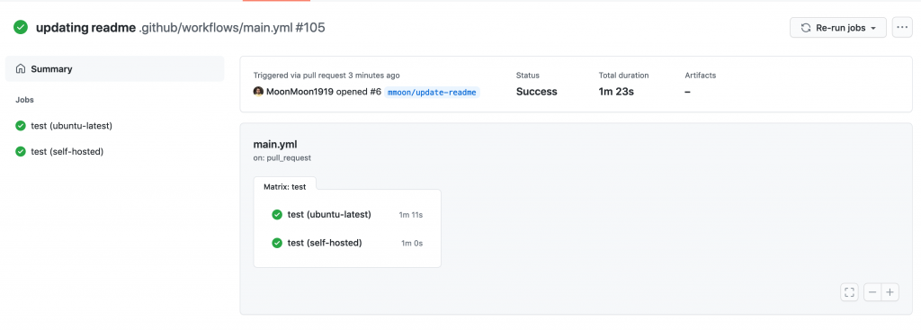
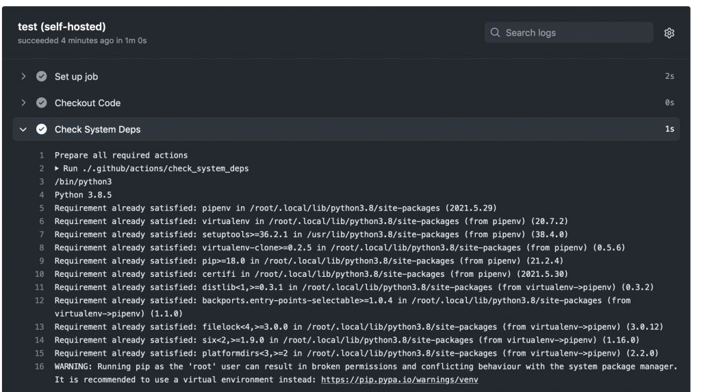
This post will teach you to set up an AWS Graviton2 instance as a self-hosted runner for GitHub Actions. We will verify the runner is added to the default runner group for a GitHub Organization, which can only be used by private repositories by default. Then, we’ll walk through setting up a continuous integration workflow in GitHub Actions that runs on the self-hosted Graviton2 runner and hosted x86 runners.

Overview

This post will cover the following:

  • Network configurations for deploying a self-hosted runner on EC2.
  • Generating a GitHub token for a GitHub organization, and then storing the token and organization URL in AWS Systems Manager Parameter Store.
  • Configuring a self-hosted GitHub runner on EC2.
  • Deploying the network and EC2 resources by using the AWS Cloud Development Kit (AWS CDK).
  • Adding Graviton2 self-hosted runners to a workflow for GitHub Actions to an example Python application.
  • Running the workflow.

Prerequisites

  1. An AWS account with permissions to create the necessary resources.
  2. A GitHub account: This post assumes that you have the required permissions as a GitHub organization admin to configure your GitHub organization, as well as create workflows.
  3. Familiarity with the AWS Command Line Interface (AWS CLI).
  4. Access to AWS CloudShell.
  5. Access to an AWS account with administrator or PowerUser (or equivalent) AWS Identity and Access Management (IAM) role policies attached.
  6. Account capacity for two Elastic IPs for the NAT gateways.
  7. An IPv4 CIDR block for a new Virtual Private Cloud (VPC) that is created as part of the AWS CDK stack.

Security

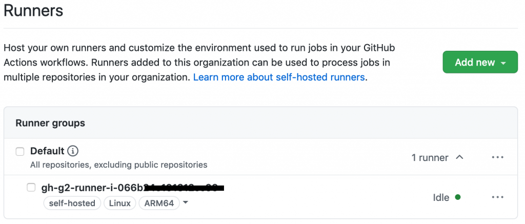
We’ll be adding the self-hosted runner at the GitHub organization level. This makes the runner available for use by the private repositories belonging to the GitHub organization. When new runners are created for an organization, they are automatically assigned to the default self-hosted runner group, which, by default, cannot be utilized by public repositories.

You can verify that your self-hosted runner group is only available to private repositories by navigating to the Actions section of your GitHub Organization’s settings. Select the “Runner Groups” submenu then the Default runner group and confirm that “Allow public repositories” is not checked.

GitHub recommends only utilizing self-hosted runners with private repositories. Allowing self-hosted runners on public repositories and allowing workflows on public forks introduces a significant security risk. More information about the risks can be found in self-hosted runner security with public repositories.

In this post, we verified that for the default runner group, allowing public repositories is not enabled.

AWS CDK

To model and deploy our architecture, we use the AWS CDK. The AWS CDK lets us design components for a self-hosted runner that are customizable and shareable in several popular programming languages.

Our AWS CDK application is defined by two stacks (VPC and EC2) that we’ll use to create the networking resources and our self-hosted runner on EC2.

Network Configuration

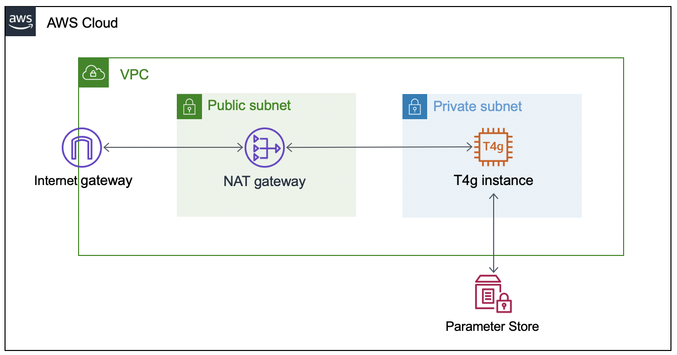
This section will walk through the networking resources that the CDK stack will create in order to support this architecture. We are deploying our self-hosted runner in a private subnet. A NAT gateway in a public subnet lets the runner make requests to GitHub, but not direct access to the instance from the internet.

  • Virtual Private Cloud – Defines a VPC across two Availability Zones with an IPv4 CIDR block that you set.
  • Public Subnet – A NAT Gateway will be created in each public subnet for outbound traffic through the VPC’s internet gateway.
  • Private Subnet – Contains the EC2 instance for the self-hosted runner that routes internet bound traffic through a NAT gateway in the public subnet.

AWS architecture diagram for self-hosted runner.

Configuring the GitHub Runner on EC2

To successfully provision the instance, we must  supply the GitHub organization URL and token. To accomplish this, we’ll create two AWS Systems Manager Parameter Store values (gh-url and gh-token), which will be accessed via the EC2 instance user data script when the CDK application deploys the EC2 stack. The EC2 instance will only be accessible through AWS Systems Manager Session Manager.

Get a Token From GitHub

The following steps are based on these instructions for adding self-hosted runners – GitHub Docs.

  1. Navigate to the private GitHub organization where you’d like to configure a custom GitHub Action Runner.
  2. Under your repository name, organization, or enterprise, click Settings.
  3. In the left sidebar, click Actions, then click Runners.
  4. Under “Runners”, click Add runner.
  5. Copy the token value under the “Configure” section.

NOTE: this is an automatically generated time-limited token for authenticating the request.

Create the AWS Systems Manager Parameter Store Values

Next, launch an AWS CloudShell environment, and then create the following AWS Systems Manager Parameter Store values in the AWS account where you’ll be deploying the AWS CDK stack.

The names gh-url and gh-token, and types String and SecureString, respectively, are required for this integration:

#!/bin/bash
aws ssm put-parameter --name gh-token --type SecureString --value ABCDEFGHIJKLMNOPQRSTUVWXYZABC
aws ssm put-parameter --name gh-url --type String --value https://github.com/your-url

Self-Hosted Runner Configuration

The EC2 instance user data script will install all required packages, and it will register the GitHub Runner application using the gh-url and gh-token parameters from the AWS Systems Manager Parameter Store. These parameters are stored as variables (TOKEN and REPO) in order to configure the runner.

This script runs automatically when the EC2 instance is launched, and it is included in the GitHub repository. We’ll utilize Amazon Linux 2 for the operating system on the runner instance.

#!/bin/bash
yum update -y
# Download and build a recent version of International Components for Unicode.
# https://github.com/actions/runner/issues/629
# https://github.com/dotnet/core/blob/main/Documentation/linux-prereqs.md
# Install jq for parsing parameter store
yum install -y libicu60 jq
# Get the latest runner version
VERSION_FULL=$(curl -s https://api.github.com/repos/actions/runner/releases/latest | jq -r .tag_name)
RUNNER_VERSION="${VERSION_FULL:1}"


# Create a folder
mkdir /home/ec2-user/actions-runner && cd /home/ec2-user/actions-runner || exit
# Download the latest runner package
curl -o actions-runner-linux-arm64-${RUNNER_VERSION}.tar.gz -L https://GitHub.com/actions/runner/releases/download/v${RUNNER_VERSION}/actions-runner-linux-arm64-${RUNNER_VERSION}.tar.gz
# Extract the installer
tar xzf ./actions-runner-linux-arm64-${RUNNER_VERSION}.tar.gz
chown -R ec2-user /home/ec2-user/actions-runner
REGION=$(curl -s http://169.254.169.254/latest/meta-data/placement/region)
INSTANCE_ID=$(curl -s http://169.254.169.254/latest/meta-data/instance-id)
TOKEN=$(aws ssm get-parameter --region "${REGION}" --name gh-token --with-decryption | jq -r '.Parameter.Value')
REPO=$(aws ssm get-parameter --region "${REGION}" --name gh-url | jq -r '.Parameter.Value')
sudo -i -u ec2-user bash << EOF
/home/ec2-user/actions-runner/config.sh --url "${REPO}" --token "${TOKEN}" --name gh-g2-runner-"${INSTANCE_ID}" --work /home/ec2-user/actions-runner --unattended
EOF
./svc.sh install
./svc.sh start

Deploying the Network Resources and Self-Hosted Runner

In this section, we’ll deploy the network resources and EC2 instance for the self-hosted GitHub runner using the AWS CDK.

From the same CloudShell environment, run the following commands in order to deploy the AWS CDK application:

#!/bin/bash
sudo npm install aws-cdk -g
git clone https://github.com/aws-samples/cdk-graviton2-gh-sh-runner.git
cd cdk-graviton2-gh-sh-runner
python3 -m venv .venv
source .venv/bin/activate
python -m pip install -r requirements.txt
export VPC_CIDR="192.168.0.0/24" # Set your CIDR here.
export AWS_ACCOUNT=`aws sts get-caller-identity | jq -r '.Account'`
cdk bootstrap aws://$AWS_ACCOUNT/$AWS_REGION
cdk deploy --all
# Note: Before the EC2 stack deploys you will be prompted for approval
# The message states 'This deployment will make potentially sensitive changes according to your current security approval level (--require-approval broadening).' and prompts for y/n

These steps will deploy an EC2 instance self-hosted runner that is added to your GitHub organization (as previously specified by the gh-url parameter). Confirm the self-hosted runner has been successfully added to your organization by navigating to the Settings tab for your GitHub organization, selecting the Actions options from the left-hand panel, and then selecting Runners.

Default runner group including an ARM64 self-hosted runner.

Extending a Workflow to use the self-hosted Runner

This section will walk through setting up a GitHub Actions workflow to extend a test pipeline for an example application. We’ll define a workflow that runs a series of static code checks and unit tests on both x86 and ARM.

Our example application is an online bookstore where users can find books, add them to their cart, and create orders. The application is written in Python using the Flask framework, and it uses Amazon DynamoDB for data storage.

Actions expect the workflow to be defined in the folder .github/workflows and the extension of either .yaml or .yml. We’ll create the directory, as well as an empty file inside the directory called main.yml.

#!/bin/bash
mkdir -p .github/workflows
touch .github/workflows/main.yml

First, we must define when our workflow will run. We’ll define the workflow to run when pull requests are created, synchronized (new commits are pushed), or re-opened, and then on push to the main branch.

# main.yml
on:
  pull_request:
    types: [opened, synchronize, reopened]
  push:
    branches:
      - main

Next, define the workflow by adding jobs. Each job can have one or more steps to run. A step defines a command, set up task, or action that will be run. You can also create custom Actions with user-defined steps and repeatable modules.

Next, we’ll define a single job test to include every step of our workflow, as well as a strategy for the job to run the workflow on both x86 and the Graviton2 self-hosted runner. We’ll specify both ubuntu-latest, a hosted runner, and self-hosted for our Graviton2 runner. This lets our workflow run in parallel on two different CPUs, and it is not disruptive of existing processes.

# main.yml
jobs:
  test:
    runs-on: ${{ matrix.os }}
    strategy:
      fail-fast: false
      matrix:
        os: [ubuntu-latest, self-hosted]

Now we can add steps that each runner will run. We’ll be using custom Actions that we create for each step, as well as the pre-built action checkout for pulling down the latest changes to each runner.

GitHub Actions expects all custom actions to be defined in .github/actions/<name of action>/action.yml. We’ll define four custom Actions – check_system_deps, check_and_install_app_deps, run_static_checks, and run_unit_tests.

#!/bin/bash
for action in check_system_deps check_and_install_app_deps run_static_checks run_unit_tests; do \
    mkdir -p .github/actions/${action} && \
    touch .github/actions/${action}/action.yml; \
    done

We define an Action with a series of steps to ensure that the runner is prepared to run our tests and checks:

  1. Check that Python3 is installed
  2. Check that pipenv is installed

Our using statement specifies “composite” to run all steps as a single action.

# .github/actions/check_system_deps/action.yml
name: "Check System Deps"
description: "Check for Python 3.x, list version, Install pipenv if it is not installed"
runs:
  using: "composite"
  steps:
    - name: Check For Python3.x
      run: |
        which python3
        VERSION=$(python3 --version | cut -d ' ' -f 2)
        VERSION_PATCH=$(echo ${VERSION} | cut -d '.' -f 2)
        [ $VERSION_PATCH -ge 8 ]
      shell: bash
    - name: Install Pipenv
      run: python3 -m pip install pipenv --user
      shell: bash

Now that we have the correct version of Python and a package manager installed, we’ll create an action to install our application dependencies:

# .github/actions/check_and_install_app_deps/action.yml
name: "Install deps"
description: "Install application dependencies"
runs:
  using: "composite"
  steps:
    - name: Install deps
      run: python3 -m pipenv install --dev
      shell: bash

Next, we’ll create an action to run all of our static checks. For our example application, we want to perform the following checks:

  1. Check for security vulnerabilities using Bandit
  2. Check the cyclomatic complexity using McCabe
  3. Check for code that has no references using Vulture
  4. Perform a static type check using MyPy
  5. Check for open CVEs in dependencies using Safety
# .github/actions/run_static_checks/action.yml
name: "Run Static Checks"
description: "Run static checks for the python app"
runs:
  using: "composite"
  steps:
    - name: Check common sense security issues
      run: python3 -m pipenv run bandit -r graviton2_gh_runner_flask_app/
      shell: bash
    - name: Check Cyclomatic Complexity
      run: python3 -m pipenv run flake8 --max-complexity 10 graviton2_gh_runner_flask_app
      shell: bash
    - name: Check for dead code
      run: python3 -m pipenv run vulture graviton2_gh_runner_flask_app --min-confidence 100
      shell: bash
    - name: Check static types
      run: python3 -m pipenv run mypy graviton2_gh_runner_flask_app
      shell: bash
    - name: Check for CVEs
      run: python3 -m pipenv check
      shell: bash

We’ll create an action to run the unit tests using PyTest.

# .github/actions/run_unit_tests/action.yml
name: "Run Unit Tests"
description: "Run unit tests for python app"
runs:
  using: "composite"
  steps:
    - name: Run PyTest
      run: python3 -m pipenv run pytest -sv tests
      shell: bash

Finally, we’ll bring all of these actions into our steps in main.yml in order to define every step that will be run on each runner any time that our workflow is run.

# main.yml
steps:
   - name: Checkout Code
     uses: actions/checkout@v2
   - name: Check System Deps
     uses: ./.github/actions/check_system_deps
   - name: Install deps
     uses: ./.github/actions/check_and_install_app_deps
   - name: Run Static Checks
     uses: ./.github/actions/run_static_checks
   - name: Run PyTest
     uses: ./.github/actions/run_unit_tests

Save the file.

Running the Workflow

The workflow will run on the runners when you commit and push your changes. To demonstrate, we’ll create a PR to update the README of our example app in order to kick off the workflow.

After the change is pushed, see the status of your workflow by navigating to your repository in the browser. Select the Actions tab. Select your workflow run from the list of All Workflows. This opens the Summary page for the workflow run.

Successful run of jobs on hosted Ubuntu and self-hosted ARM64 runners.

As each step defined in the workflow job runs, view their details by clicking the job name on the left-hand panel or on the graph representation. The following images are screenshots of the jobs, and example outputs of each step. First, we have check_system_deps.

Successful run of a custom action checking for required system dependencies.

We’ve excluded a screenshot of check_and_install_app_deps that shows the output of pipenv install. Next, we can see that our change passes for our run_static_checks Action (first), and unit tests for our run_unit_tests Action (second).

Successful run of a custom action checking for required system dependencies.

Successful run of a custom action running unit tests with PyTest.

Finally, our workflow completes successfully!

Successful run of jobs on hosted and self-hosted runners.

Clean up

To delete the AWS CDK stacks, launch CloudShell and enter the following commands:

#!/bin/bash
cd cdk-graviton2-gh-sh-runner
source .venv/bin/activate
# Re-set the environment variables again if required
# export VPC_CIDR="192.168.0.0/24" # Set your CIDR here.
cdk destroy --all

Conclusion

This post covered the configuring of a self-hosted GitHub Runner on an EC2 instance with a Graviton2 processor, the required network resources, and a workflow that will run on the Runner on each repository push or pull request for the example application. The Runner is configured at the Organization level, which by default only allows access by private repositories. Lastly, we showed an example run of the workflow after creating a pull request for our example app.

Self-hosted runners on Graviton2 for GitHub Actions lets you add ARM64 to your CICD workflows, accelerating migrations to take advantage of the price and performance of Graviton2. In this blog we’ve utilized a strategy to create a build matrix to run jobs on hosted and self-hosted runners.

We could further extend this workflow by automating deployment with AWS CodeDeploy or sending a build status notification to Slack. To reduce the cost of idle resources during periods without builds, you can set up an Amazon CloudWatch Event to schedule a stop and start of the instance during business hours.

Github Actions also supports ephemeral self-hosted runners, which automatically unregister runners from the service. Ephemeral runners are a good choice for self-managed environments where you need each job to run on a clean image.

For more examples of how to create development environments using AWS Graviton2 and AWS CDK, reference Building an ARM64 Rust development environment using AWS Graviton2 and AWS CDK.