Tag Archives: AWS Cloud Map

Implementing lightweight on-premises API connectivity using inverting traffic proxy

Post Syndicated from Oleksiy Volkov original https://aws.amazon.com/blogs/architecture/implementing-lightweight-on-premises-api-connectivity-using-inverting-traffic-proxy/

This post will explore the use of lightweight application inversion proxy as a solution for multi-point hybrid or multi-cloud, API-level connectivity for cases where AWS Direct Connect or VPN may not be practical. Then, we will present a sample solution and explain how it addresses typical challenges involved in this space.

Defining the issue

Large ISV providers and integration vendors often need to have API-level integration between a central cloud-based system and a number of on-premises APIs. Use cases can range from refactoring/modernization initiatives to interfacing with legacy on-premises applications, which have no direct migration path to the cloud.

The typical approach is to use VPN or Direct Connect, as they can provide significant benefits in terms of latency and security. However, they are not always practical in situations involving multi-source systems deployed by various groups or organizations that may have significant budget, process, or timeline constraints.

Conceptual solution

An option that addresses the connectivity need is an inverting application proxy, which can be deployed as a lightweight executable on an on-premises backend. The locally deployed agent can communicate with the proxy server on AWS using an inverted communication pattern. This means that the agent will establish outbound connection to the proxy, and it will use the connection to receive inbound requests, too. Figure 1 describes a sample architecture using inverting proxy pattern using Amazon API Gateway façade.

Inverting application proxy

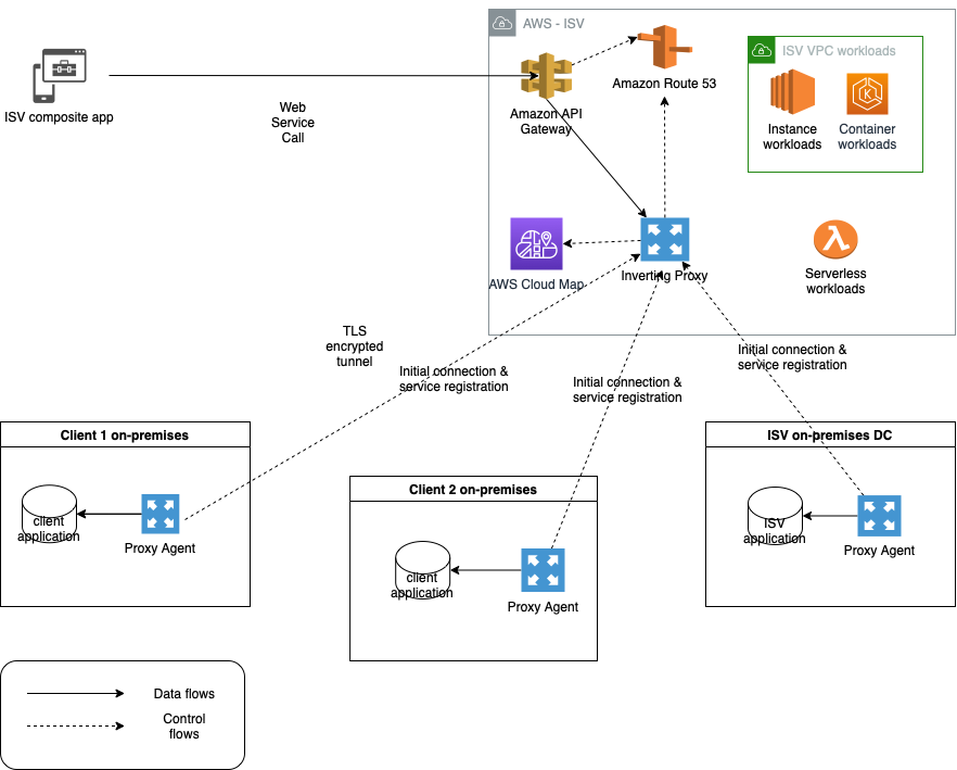
Figure 1. Inverting application proxy

The advantages of this approach include ease-of-deployment (drop-in executable agent) and -configuration. As the proxy inverts the direction of application connectivity to originate from on-premises servers, the local firewall does not need to be reconfigured to open additional ports needed for traditional proxy deployment.

Realizing the solution on AWS

We have built a sample traffic routing solution based on the original open-source Inverting Proxy and Agent by Ian Maddox, Jason Cooke, and Omar Janjur. The solution is written in Go and leverages multiple AWS services to provide additional telemetry, security, and discoverability capabilities that address the common needs of enterprise customers.

The solution is comprised of an inverting proxy and a forwarding agent. The inverting proxy is deployed on AWS as a stand-alone executable running on Amazon Elastic Compute Cloud (EC2) and responsible for forwarding traffic to the agent. The agent can be deployed as a binary or container within the target on-premises system.

Upon starting, the agent will establish an outbound connection with the proxy and local sever application. Once established, the proxy will use it in reverse to forward all incoming client requests through the agent and to the backend application. The connection is secured by Transport Layer Security (TLS) to protect communications between client and proxy and between agent and backend application.

This solution uses a unique backend ID and IAM user/role tags to identify different backend servers and control access to proxies. The backend ID is passed as a command-line parameter to the agent. The agent checks the IAM account or IAM role Amazon EC2 is running under for tag “AllowedBackends”. The tag contains coma-separated list of backend IDs that the agent is allowed to access. The connectivity is established only if the provided backend ID matches one of the values in the coma-separated list.

The solution supports native integration with AWS Cloud Map to enable automatic discoverability of remote API endpoints. Upon start and once the IAM access control checks are successfully validated, the agent can register the backend endpoints within AWS Cloud Map using a provided service name and service namespace ID.

Inverting proxy agent can collect telemetry and automatically publish it to Amazon CloudWatch using a custom namespace. This includes HTTP response codes and counts from server application aggregated by the backend ID.

For full list of options, features, and supported configurations, use --help command-line parameter with both agent and proxy executables.

Enabling highly resilient proxy deployment

For production scenarios that require high availability, deploy a pair of inverting proxies connecting to a pair of agents deployed on separate EC2 instances. The entire configuration is then placed behind Application Load Balancer to provide a single point of ingress, load-balancing, and health-checking functionality. Figure 2 demonstrates a highly resilient setup for critical workloads.

Highly resilient deployment diagram for inverting proxy

Figure 2. Highly resilient deployment diagram for inverting proxy

Additionally, for real-life production workloads dealing with sensitive data, we recommend following security and resilience best practices for Amazon EC2.

Deploying and running the solution

The solution includes a simple demo Node.js server application to simulate connectivity with an inverting proxy. A restrictive security group will be used to simulate on-premises data center.

Steps to deployment:

1. Create a “backend” Amazon EC2 server using Linux 2, free-tier AMI. Ensure that Port 443 (inbound port for sample server application) is blocked from external access via appropriate security group.

2. Connect by using SSH into target server run updates.

sudo yum update -y

3. Install development tools and dependencies:

sudo yum groupinstall "Development Tools" -y

4. Install Golang:

sudo yum install golang -y

5. Install node.js.

curl -o- https://raw.githubusercontent.com/nvm-sh/nvm/v0.34.0/install.sh | bash

. ~/.nvm/nvm.sh

nvm install 16

6. Clone the inverting proxy GitHub repository to the “backend” EC2 instance.

7. From inverting-proxy folder, build the application by running:

mkdir /home/ec2-user/inverting-proxy/bin

export GOPATH=/home/ec2-user/inverting-proxy/bin

make

8. From /simple-server folder, run the sample appTLS application in the background (see instructions below). Note: to enable SSL you will need to generate encryption key and certificate files (server.crt and server.key) and place them in simple-server folder.

npm install

node appTLS &

Example app listening at https://localhost:443

Confirm that the application is running by using ps -ef | grep node:

ec2-user  1700 30669  0 19:45 pts/0    00:00:00 node appTLS

ec2-user  1708 30669  0 19:45 pts/0    00:00:00 grep --color=auto node

9. For backend Amazon EC2 server, navigate to Amazon EC2 security settings and create an IAM role for the instance. Keep default permissions and add “AllowedBackends” tag with the backend ID as a tag value (the backend ID can be any string that matches the backend ID parameter in Step 13).

10. Create a proxy Amazon EC2 server using Linux AMI in a public subnet and connect by using SSH in an Amazon EC2 once online. Copy the contents of the bin folder from the agent EC2 or clone the repository and follow build instructions above (Steps 2-7).

Note: the agent will be establishing outbound connectivity to the proxy; open the appropriate port (443) in the proxy Amazon EC2 security group. The proxy server needs to be accessible by the backend Amazon EC2 and your client workstation, as you will use your local browser to test the application.

11. To enable TLS encryption on incoming connections to proxy, you will need to generate and upload the certificate and private key (server.crt and server.key) to the bin folder of the proxy deployment.

12. Navigate to /bin folder of the inverting proxy and start the proxy by running:

sudo ./proxy –port 443 -tls

2021/12/19 19:56:46 Listening on [::]:443

13. Use the SSH to connect into the backend Amazon EC2 server and configure the inverting proxy agent. Navigate to /bin folder in the cloned repository and run the command below, replacing uppercase strings with the appropriate values. Note: the required trailing slash after the proxy DNS URL.

./proxy-forwarding-agent -proxy https://YOUR_PROXYSERVER_PUBLIC_DNS/ -backend SampleBackend-host localhost:443 -scheme https

14. Use your local browser to navigate to proxy server public DNS name (https://YOUR_PROXYSERVER_PUBLIC_DNS). You should see the following response from your sample backend application:

Hello World!

Conclusion

Inverting proxy is a flexible, lightweight pattern that can be used for routing API traffic in non-trivial hybrid and multi-cloud scenarios that do not require low-latency connectivity. It can also be used for securing existing endpoints, refactoring legacy applications, and enabling visibility into legacy backends. The sample solution we have detailed can be customized to create unique implementations and provides out-of-the-box baseline integration with multiple AWS services.

Improving Performance and Reducing Cost Using Availability Zone Affinity

Post Syndicated from Michael Haken original https://aws.amazon.com/blogs/architecture/improving-performance-and-reducing-cost-using-availability-zone-affinity/

One of the best practices for building resilient systems in Amazon Virtual Private Cloud (VPC) networks is using multiple Availability Zones (AZ). An AZ is one or more discrete data centers with redundant power, networking, and connectivity. Using multiple AZs allows you to operate workloads that are more highly available, fault tolerant, and scalable than would be possible from a single data center. However, transferring data across AZs adds latency and cost.

This blog post demonstrates an architectural pattern called “Availability Zone Affinity” that improves performance and reduces costs while still maintaining the benefits of Multi-AZ architectures.

Cross Availability Zone effects

AZs are physically separated by a meaningful distance from other AZs in the same AWS Region. Although they all are within 60 miles (100 kilometers) of each other. This produces roundtrip latencies usually under 1-2 milliseconds (ms) between AZs in the same Region. Roundtrip latency between two instances in the same AZ is closer to 100-300 microseconds (µs) when using enhanced networking.1 This can be even lower when the instances use cluster placement groups. Additionally, when data is transferred between two AZs, data transfer charges apply in both directions.

To better understand these effects, we’ll analyze a fictitious workload, the “foo service,” shown in Figure 1. The foo service provides a storage platform for other workloads in AWS to redundantly store data. Requests are first processed by an Application Load Balancer (ALB). ALBs always use cross-zone load balancing to evenly distribute requests to all targets. Next, the request is sent from the load balancer to a request router. The request router performs a few operations, like authorization checks and input validation, before sending it to the storage tier. The storage tier replicates the data sequentially from the lead node, to the middle node, and finally the tail node. Once the data has been written to all three nodes, it is considered committed. The response is sent from the tail node back to the request router, back through the load balancer, and finally returned to the client.

An example system that transfers data across AZs

Figure 1. An example system that transfers data across AZs

We can see in Figure 1 that, in the worst case, the request traversed an AZ boundary eight times. Let’s calculate the fastest possible, zeroth percentile (p0), latency. We’ll assume the best time for non-network processing of the request in the load balancer, request router, and storage tier is 4 ms. If we consider 1 ms as the minimum network latency added for each AZ traversal, in the worst-case scenario of eight AZ traversals, the total processing time can be no faster than 12 ms. At the 50th percentile (p50), meaning the median, let’s assume the cross-AZ latency is 1.5 ms and non-network processing is 8 ms, resulting in a total of 20 ms for overall processing. Additionally, if this system is processing millions of requests, the data transfer charges could become substantial over time. Now, let’s imagine that a workload using the foo service must operate with p50 latency under 20 ms. How can the foo service change their system design to meet this goal?

Availability Zone affinity

The AZ Affinity architectural pattern reduces the number of times an AZ boundary is crossed. In the example system we looked at in Figure 1, AZ Affinity can be implemented with two changes.

  1. First, the ALB is replaced with a Network Load Balancer (NLB). NLBs provide an elastic network interface per AZ that is configured with a static IP. NLBs also have cross-zone load balancing disabled by default. This ensures that requests are only sent to targets that are in the same AZ as the elastic network interface that receives the request.
  2. Second, DNS entries are created for each elastic network interface to provide an AZ-specific record using the AZ ID, which is consistent across accounts. Clients use that DNS record to communicate with a load balancer in the AZ they select. So instead of interacting with a Region-wide service using a DNS name like foo.com, they would instead use use1-az1.foo.com.

Figure 2 shows the system with AZ Affinity. We can see that each request, in the worst case, only traverses an AZ boundary four times. Data transfer costs are reduced by approximately 40 percent compared to the previous implementation. If we use 300 μs as the p50 latency for intra-AZ communication, we now get (4×300μs)+(4×1.5ms)=7.2ms. Using the median 8 ms processing time, this brings the overall median latency to 15.2 ms. This represents a 40 percent reduction in median network latency. When thinking about p90, p99, or even p99.9 latencies, this reduction could be even more significant.

The system now implements AZ Affinity

Figure 2. The system now implements AZ Affinity

Figure 3 shows how you could take this approach one step farther using service discovery. Instead of requiring the client to remember AZ-specific DNS names for load balancers, we can use AWS Cloud Map for service discovery. AWS Cloud Map is a fully managed service that allows clients to look up IP address and port combinations of service instances using DNS and dynamically retrieve abstract endpoints, like URLs, over the HTTP-based service Discovery API. Service discovery can reduce the need for load balancers, removing their cost and added latency.

The client first retrieves details about the service instances in their AZ from the AWS Cloud Map registry. The results are filtered to the client’s AZ by specifying an optional parameter in the request. Then they use that information to send requests to the discovered request routers.

AZ Affinity implemented using AWS Cloud Map for service discovery

Figure 3. AZ Affinity implemented using AWS Cloud Map for service discovery

Workload resiliency

In the new architecture using AZ Affinity, the client has to select which AZ they communicate with. Since they are “pinned” to a single AZ and not load balanced across multiple AZs, they may see impact during an event affecting the AWS infrastructure or foo service in that AZ.

During this kind of event, clients can choose to use retries with exponential backoff or send requests to the other AZs that aren’t impacted. Alternatively, they could implement a circuit breaker to stop making requests from the client in the affected AZ and only use clients in the others. Both approaches allow them to use the resiliency of Multi-AZ systems while taking advantage of AZ Affinity during normal operation.

Client libraries

The easiest way to achieve the process of service discovery, retries with exponential backoff, circuit breakers, and failover is to provide a client library/SDK. The library handles all of this logic for users and makes the process transparent, like what the AWS SDK or CLI does. Users then get two options, the low-level API and the high-level library.

Conclusion

This blog demonstrated how the AZ Affinity pattern helps reduce latency and data transfer costs for Multi-AZ systems while providing high availability. If you want to investigate your data transfer costs, check out the Using AWS Cost Explorer to analyze data transfer costs blog for an approach using AWS Cost Explorer.

For investigating latency in your workload, consider using AWS X-Ray and Amazon CloudWatch for tracing and observability in your system. AZ Affinity isn’t the right solution for every workload, but if you need to reduce inter-AZ data transfer costs or improve latency, it’s definitely an approach to consider.


  1. This estimate was made using t4g.small instances sending ping requests across AZs. The tests were conducted in the us-east-1, us-west-2, and eu-west-1 Regions. These results represent the p0 (fastest) and p50 (median) intra-AZ latency in those Regions at the time they were gathered, but are not a guarantee of the latency between two instances in any location. You should perform your own tests to calculate the performance enhancements AZ Affinity offers.

Configuring private integrations with Amazon API Gateway HTTP APIs

Post Syndicated from Eric Johnson original https://aws.amazon.com/blogs/compute/configuring-private-integrations-with-amazon-api-gateway-http-apis/

This post was written by Michael Hume – AWS Solutions Architect Public Sector UKIR.

Customers often want to use Amazon API Gateway REST APIs to send requests to private resources. This feature is useful for building secure architectures using Amazon EC2 instances or container-based services on Amazon ECS or Amazon EKS, which reside within a VPC.

Private integration is possible for REST APIs by using Network Load Balancers (NLB). However, there may be a requirement for private integration with an Application Load Balancer (ALB) or AWS Cloud Map. This capability is built into Amazon API Gateway HTTP APIs, providing customers with three target options and greater flexibility.

You can configure HTTP APIs with a private integration as the front door or entry point to an application. This enables HTTPS resources within an Amazon VPC to be accessed by clients outside of the VPC. This architecture also provides an application with additional HTTP API features such as throttling, cross-origin resource sharing (CORS), and authorization. These features are then managed by the service instead of an application.

HTTP APIs and Application Load Balancers

In the following architecture, an HTTP APIs endpoint is deployed between the client and private backend resources.

HTTP APIs to ALB example

HTTP APIs to ALB example

A VPC link encapsulates connections between API Gateway and targeted VPC resources. HTTP APIs private integration methods only allow access via a VPC link to private subnets. When a VPC link is created, API Gateway creates and manages the elastic network interfaces in a user account. VPC links are shared across different routes and APIs.

Application Load Balancers can support containerized applications. This allows ECS to select an unused port when scheduling a task and then registers that task with a target group and port. For private integrations, an internal load balancer routes a request to targets using private IP addresses to resources that reside within private subnets. As the Application Load Balancer receives a request from an HTTP APIs endpoint, it looks up the listener rule to identify a protocol and port. A target group then forwards requests to an Amazon ECS cluster, with resources on underlying EC2 instances. Targets are added and removed automatically as traffic to an application changes over time. This increases the availability of an application and provides efficient use of an ECS cluster.

Configuration with an ALB

To configure a private integration with an Application Load Balancer.

  1. Create an HTTP APIs endpoint, choose a route and method, and attach an integration to a route using a private resource.

    Attach integration to route

    Attach integration to route

  2. Provide a target service to send the request to an ALB/NLB.

    Integration details

    Integration details

  3. Add both the load balancer and listener’s Amazon Resource Names (ARNs), together with a VPC link.

    Load balancer settings

    Load balancer settings

HTTP APIs and AWS Cloud Map

Modern applications connect to a broader range of resources. This can become complex to manage as network locations dynamically change based on automatic scaling, versioning, and service disruptions. Its challenging, as each service must quickly find the infrastructure location of the resources it needs. Efficient service discovery of any dynamically changing resources is important for application availability.

If an application scales to hundreds or even thousands of services, then a load balancer may not be appropriate. In this case, HTTP APIs private integration with AWS Cloud Map maybe a better choice. AWS Cloud Map is a resource discovery service that provides a dynamic map of the cloud. It does this by registering application resources such as databases, queues, microservices, and other resources with custom names.

For server-side service discovery, if an application uses a load balancer, it must know the load balancer’s endpoint. This endpoint is used as a proxy, which adds additional latency. As AWS Cloud Map provides client-side service discovery, you can replace the load balancer with a service registry. Now, connections are routed directly to backend resources, instead of being proxied. This involves fewer components, making deployments safer and with less management, and reducing complexity.

Configuration with AWS Cloud Map

HTTP APIs to AWS CloudMap example

HTTP APIs to AWS CloudMap example

In this architecture, the Amazon ECS service has been configured to use Amazon ECS Service Discovery. Service discovery uses the AWS Cloud Map API and Amazon Route 53 to create a namespace. This is a logical name for a group of services. It also creates a service, which is a logical group of resources or instances. In this example, it’s a group of ECS clusters. This allows the service to be discoverable via DNS. These resources work together, to provide a service.

Service discovery configuration

Service discovery configuration

To configure a private integration with AWS Cloud Map:

  1. Create an HTTP API, choose a route and method, and attach an integration to a route using a private resource. This is as shown previously for an Application Load Balancer.
  2. Provide a target service to send requests to resources registered with AWS Cloud Map.

    Target service configuration

    Target service configuration

  3. Add both the namespace, service and VPC link.

    Namespace and VPC configuration

    Namespace and VPC configuration

Deployment

To build the solution in this blog, see the AWS CloudFormation templates in the GitHub repository and, the instructions in the README.md file.

Conclusion

This post discusses the benefits of using API Gateway’s HTTP APIs to access private resources that reside within a VPC, and how HTTP APIs provides three different private integration targets for different use cases.

If a load balancer is required, the application operates at layer 7 (HTTP, HTTPS), requires flexible application management and registering of AWS Lambda functions as targets, then use an Application Load Balancer. However, if the application operates at layer 4 (TCP, UDP, TLS), uses non-HTTP protocols, requires extreme performance and a static IP, then use a Network Load Balancer.

As HTTP APIs private integration methods to both an ALB and NLB only allow access via a VPC link. This enhances security, as resources are isolated within private subnets with no direct access from the internet.

If a service does not need a load balancer, then HTTP APIs provide further private integration flexibility with AWS Cloud Map, which automatically registers resources in a service registry. AWS Cloud Map enables filtering by providing attributes when service discovery is enabled. These can then be used as HTTP APIs integration settings to specify query parameters and filter specific resources.

For more information, watch Happy Little APIs (S2E1): Private integrations with HTTP API.