Post Syndicated from Anton Aleksandrov original https://aws.amazon.com/blogs/compute/effectively-building-ai-agents-on-aws-serverless/
Imagine an AI assistant that doesn’t just respond to prompts – it reasons through goals, acts, and integrates with real-time systems. This is the promise of agentic AI.
According to Gartner, by 2028 over 33% of enterprise applications will embed agentic capabilities – up from less than 1% today. While early generative AI efforts focused on GPUs and model training, agentic systems shift the focus to CPUs, orchestration, and integration with live data – the places where organizations are starting to see real return on investment (ROI).
In this post, you’ll learn how to build and run serverless AI agents on AWS using services such as Amazon Bedrock AgentCore (preview as of this post publication), AWS Lambda, and Amazon Elastic Container Service (Amazon ECS), which provide scalable compute foundations for agentic workloads. You’ll also explore architectural patterns, state management, identity, observability, and tool usage to support production-ready deployments.
Overview
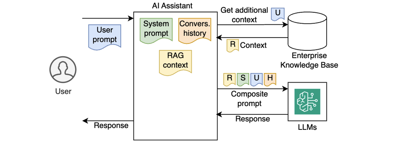
Early AI assistants were stateless and reactive – each prompt processed in isolation, with no memory of prior interactions or awareness of broader context. Gradually, AI assistants became more capable by injecting system prompts, preserving conversation history, and incorporating enterprise knowledge using Retrieval-Augmented Generation (RAG), as illustrated in the following diagram.

Despite these improvements, traditional AI assistants still lacked true autonomy. They couldn’t reason through multi-step goals, make decisions on their own, or adjust workflows dynamically based on outcomes. As a result, they worked well for simpler Q&A or predefined workflows, but struggled with dynamic, more complex, real-world tasks that require planning, using external tools, and making decisions along the way.
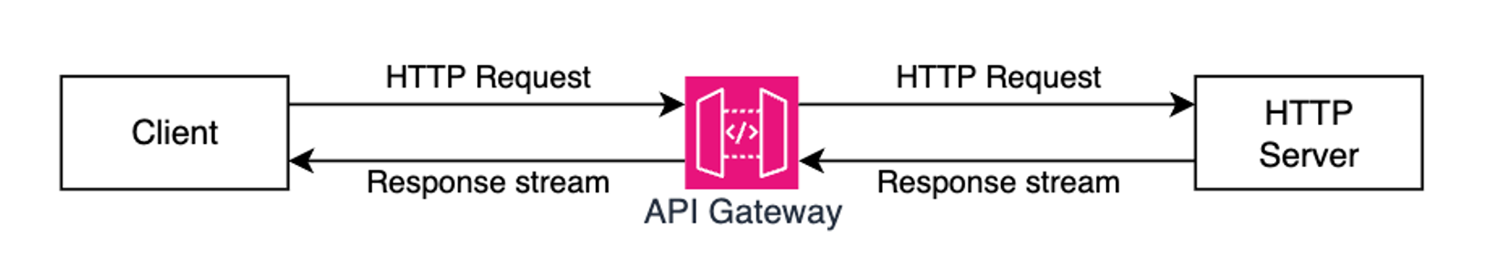
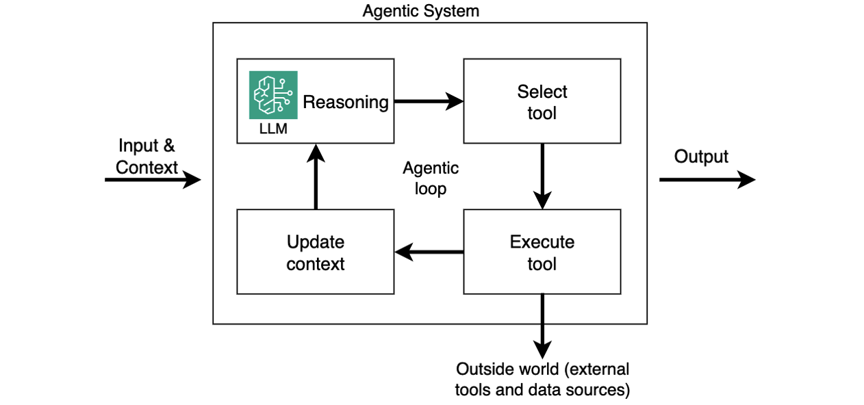
Agentic AI systems shift from passive content generation to autonomous, goal-driven behavior. Powered by Large Language Models (LLMs) and enhanced with memory, planning, and tool use, these systems can break down complex tasks into smaller steps, reason through each step, and take real-time actions, such as calling APIs, executing tools, or interacting with live data. By referencing the LLM within a control cycle that manages context, memory, and decision-making, these systems can choose the right tools, adapt workflows, and integrate deeply into enterprise environments, with use cases ranging from travel booking and financial analysis to DevOps automation and code debugging. This is referred to as an agentic loop. In this system, the agent relies on the LLM’s reasoning output to execute tools, capture tool results, and feed these results to the LLM as updated context (as shown in the following diagram). This happens in a loop until LLM instructs the agent to return the final output to the caller.

While agentic loop is a lightweight approach to structuring these systems, other control flow paradigms, such as graph, swarm, and workflows, are also available in open-source frameworks like LangGraph.
Introducing Strands Agents SDK
Strands Agents SDK is a code-first framework to build production-ready AI agents with minimal boilerplate. It utilizes the above-mentioned agentic loop system and abstracts common challenges like memory management, tool integration, and multi-step reasoning in a lightweight, modular Python framework. Strands SDK handles state, tool orchestration, and multi-step reasoning so agents can remember past conversations, call external APIs, enforce business rules, and adapt to changing inputs. This allows you to focus on the application’s business logic.
Because agents built with Strands SDK are essentially Python apps, they’re portable and can run across different compute options, such as Bedrock AgentCore Runtime, Lambda functions, ECS tasks, or even locally. This makes Strands Agents SDK a powerful foundation for building scalable and goal-driven AI systems. The following sections assume you’re running your AI agents built with Strands Agents SDK on Lambda functions.
Building your first serverless AI agent
Imagine you’re building an AI-powered corporate travel assistant on AWS, and you have the following technical requirements:
- Define the system prompts, memory, and model you want to use
- Integrate tools for API calls, business logic, and knowledge bases
- Ensure authentication and observability
Strands SDK handles heavy lifting, so you can focus on building smart, responsive agents with minimal overhead. The following code snippet creates a simple agent, according to your configuration.
from strands import Agent

agent = Agent(
    system_prompt=
      """You're a travel assistant that helps
         employees book business trips
         according to policy.""",
    model=my_model,
    tools=[get_policies, get_hotels, get_cars, book_travel]
)

response = agent("Book me a flight to NYC next Monday.")
That’s it. Your agent now has a personality, memory, and ability to use external tools. The Agent class in the Strands SDK abstracts agentic logic, such as maintaining conversation history, handling LLM interactions, orchestrating tools and external knowledge sources, and running the full agentic loop.
Session state management
Session state management is critical for agentic workflows. It allows agents to track goals across interactions – enabling coherent conversations, retaining context, and providing personalized experiences. Without state management, each prompt is handled in isolation, making it impossible for the agent to reference prior context or track ongoing tasks. In cloud environments, where applications need to be stateless and scalable, the solution is to externalize session state to persistent storage, such as Amazon Simple Storage Service (Amazon S3). This allows any agent instance to reconstruct the conversation history on demand, delivering a seamless, stateful user experience while keeping the agentic app itself stateless for scalability and resilience.

AI agents built with Strands store conversation history in the agent.messages property (see documentation). To support stateless compute environments, you can externalize the agent state, persisting it after each interaction and restoring it before the next. This preserves continuity across invocations while keeping your agent instances stateless. In user-aware agentic applications, you want to persist state for each user, typically associated with the user’s unique ID. The following example illustrates how you can do it with the built-in S3SessionManager class when running your agent in a stateless environment such as a Lambda function:
    session_manager = S3SessionManager(
        session_id=f"session_for_user_{user.id}",
        bucket=SESSION_STORE_BUCKET_NAME,
        prefix="agent_sessions"
    )

    agent = Agent(
        session_manager=session_manager
    )
When using Bedrock AgentCore, use the fully managed, serverless AgentCore Memory primitive to manage sessions and long-term memory. It provides relevant context to models while helping agents learn from past interactions. You can make Strands’ session manager work with AgentCore Memory similar to S3SessionManager.
Authentication and authorization
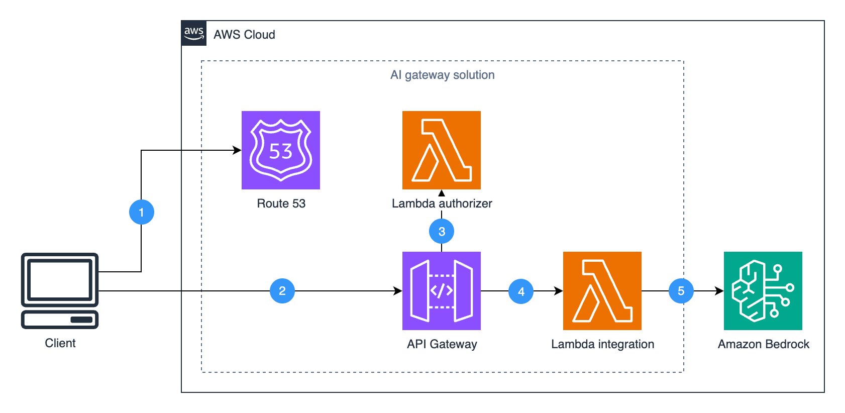
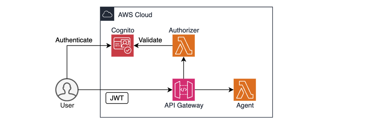
For enterprise AI agents to operate safely, they must know who the user is and what they are allowed to do. This goes beyond basic identity validation – AI agents often act on behalf of users, so they might need to enforce role-based access controls, support audit, and comply with corporate policies.

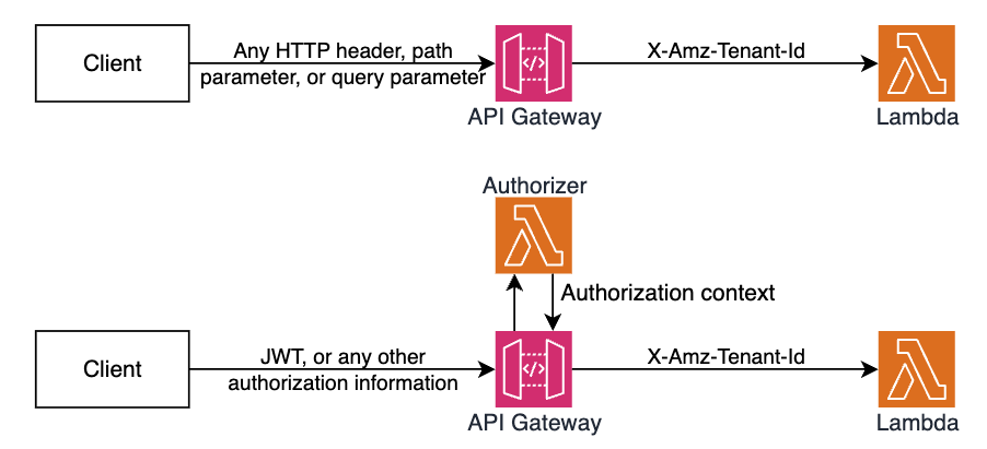
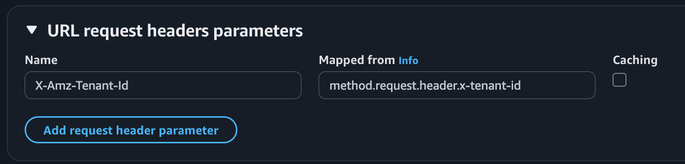
AWS services like Amazon Cognito, Amazon Identity and Access Management (IAM), and Amazon API Gateway provide a solid foundation for authentication and authorization. For example, you can use Cognito to authenticate users through user pools or federated identity providers, combined with API Gateway and Lambda authorizer to validate user access permissions before forwarding requests to the agent, as shown in the preceding diagram. IAM policies define what the agent is allowed to do. After the user is both authenticated and authorized, the agent can extract the identity context, for example, from a JSON Web Token (JWT), to personalize prompts, enforce rules, or dynamically restrict actions.
The following code snippet illustrates retrieving user’s identity from the Authorization header and passing it to an agent:
def handler(event: dict, ctx):
    user_id = extract_user_id(event["headers"]["Authorization"])
    user_prompt: dict = json.loads(event["body"])["prompt"]
    agent_response = agent.prompt(user_id, user_prompt)

    return {
        "statusCode": 200,
        "body": json.dumps({"text": agent_response.text})
    }
The identity context can become a part of the agent’s execution loop. An agent might check the user’s department before booking travel or restrict access to sensitive tools unless the user has the appropriate permissions. By integrating authentication early, you not only enhance security, but also unlock rich personalization and audit capabilities that make agents enterprise-ready from day one.
When using Bedrock AgentCore, the AgentCore Identity primitive allows your AI agents to securely access AWS services and third-party tools either on behalf of users or as themselves with pre-authorized user consent. It provides managed OAuth 2.0 supported providers for both inbound and outbound authentication. During the preview phase, AgentCore Identity supports identity providers like Amazon Cognito, Auth0 by Okta, Microsoft Entra ID, GitHub, Google, Salesforce, and Slack. Refer to the samples for implementation details.
Building portable Strands agents on AWS
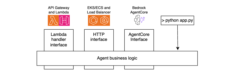
Strands Agents SDK is compute-agnostic. The agents you build are standard Python applications, which can run on any compute type.
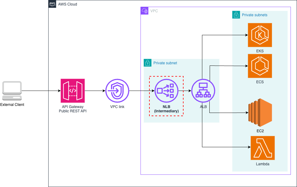
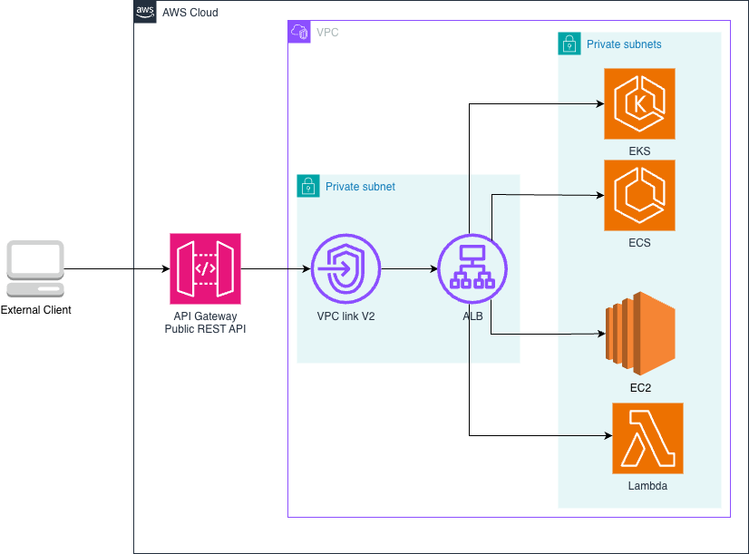
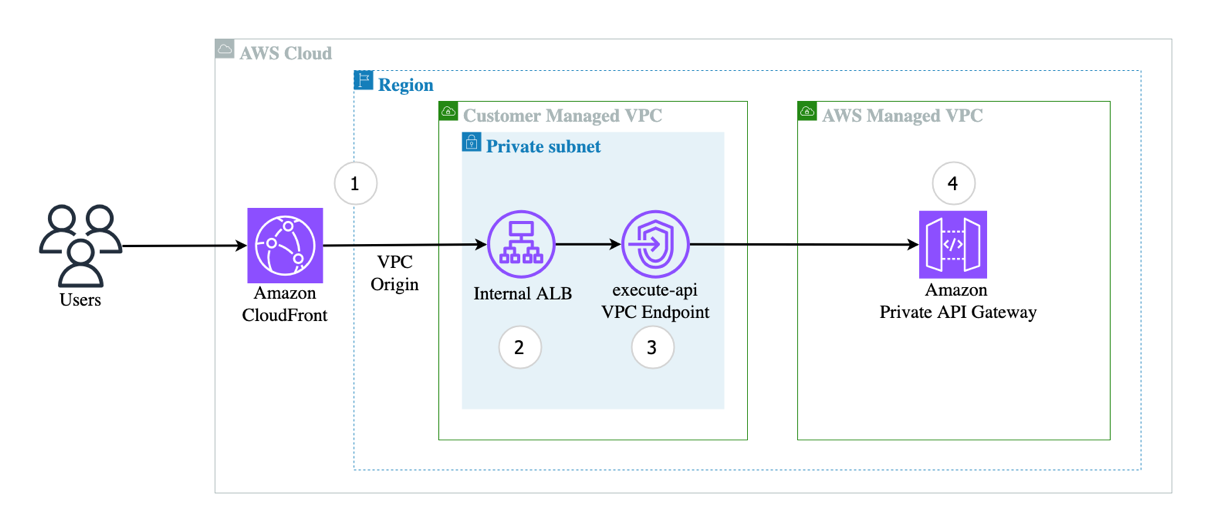
For portability and maintainability, separate your agent’s business logic from the interface layer. By doing this, you can reuse the same core agent code across environments, whether invoked through API Gateway and Lambda functions, accessed through Application Load Balancer and Amazon ECS, running on AgentCore Runtime, or even executed locally during development, as shown in the following figure.

The following code snippets illustrate this technique.
Lambda handler code:
def handler(event: dict, ctx):
     user_id = extract_user_id(event)
     user_prompt = json.loads(event["body"])["prompt"]
     agent_response = call_agent(user_id, user_prompt)
     return {
          "statusCode":200,
          "body": json.dumps({
               "text": agent_response.mesage
          })
     }
AgentCore code:
@app.entrypoint
def invoke(payload):
     user_id = extract_user_id(payload)
     user_prompt = payload.get("prompt")
     agent_response = call_agent(user_id, user_prompt)
     return {"result": agent_response.message)
HTTP Handler code:
@app.post("/prompt")
async def prompt(request: Request, prompt_request: PromptRequest):
    user_id=extract_user_id(request)
    user_prompt = prompt_request.prompt
    agent_response = call_agent(user_id, user_prompt)
    return {"text": agent_response.message)
For local testing:
if __name__ == "__main__":
     user_id="local-testing-user"
     user_prompt="book me a trip to NYC"
     agent_response = call_agent(user_id, user_prompt)
     return agent_response.message
Agent code:
def call_agent(user_id, user_prompt):
     agent = Agent(
          system_prompt="You’re a travel agent…",
          model=my_model,
          session_manager = my_session_manager,
      )
     agent_response = agent(user_prompt)
     return agent_response
Extending agent functionality with tools
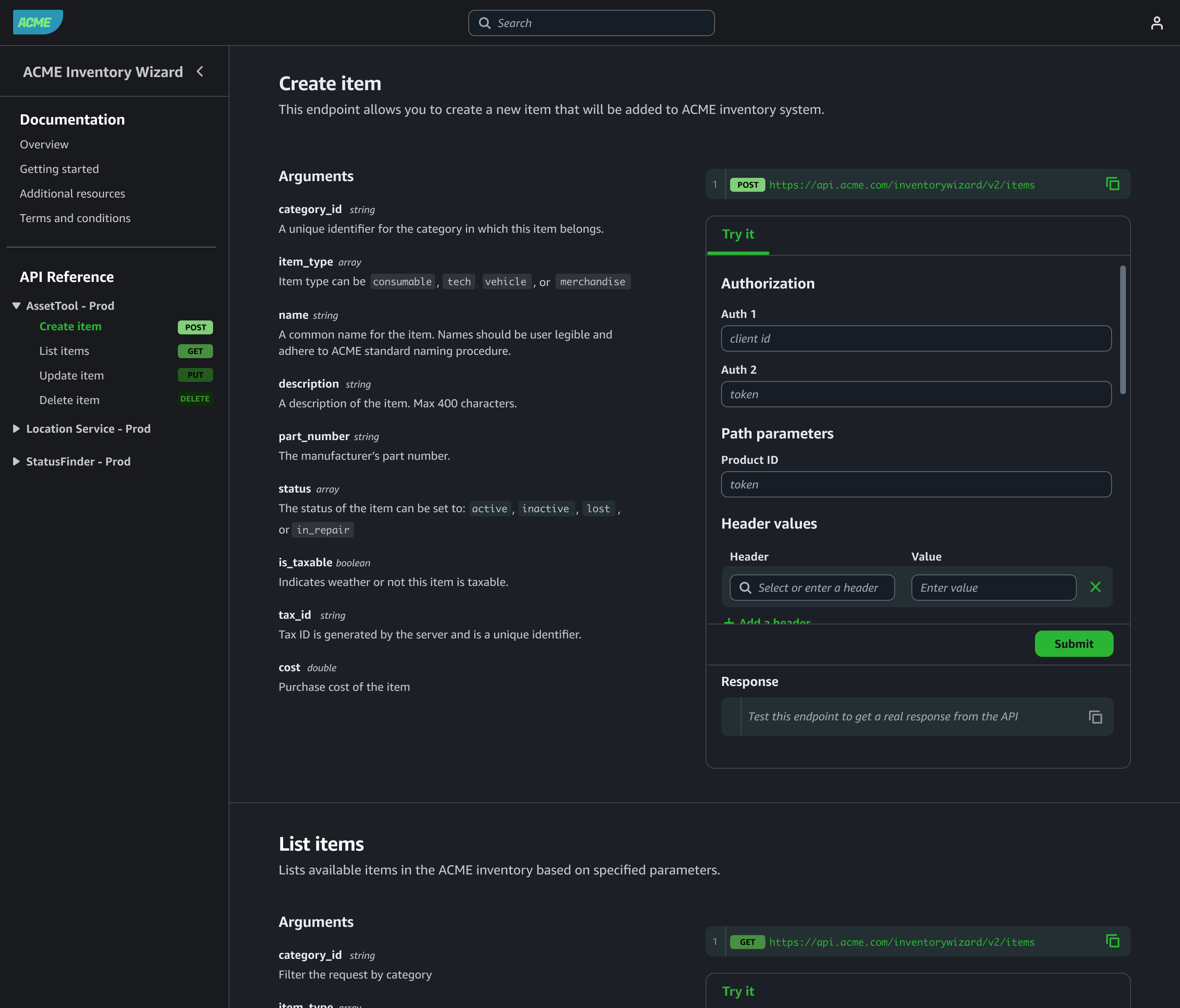
A key strength of agentic systems is their ability to invoke tools that perform actions or retrieve real-time data, enabling agents to interact with the outside world, not just generate text. The Strands Agents SDK includes built-in tools and allows you to define your own custom tools, as either in-process Python functions or external tools accessible over HTTP using the Model Context Protocol (MCP). These tools can fetch data, call APIs, or trigger workflows, and can be registered for the agent to reason over and use during execution.
The following snippet illustrates creating an in-process tool. See the documentation for more examples.
from strands import tool

@tool
def get_weather(city: str) -> str:
    weather = call_weather_api(city)
    return f"The current weather in {city} is {weather}"
Integrating with remote MCP servers
Model Context Protocol (MCP) is an open standard that decouples agents from tools using a client-server model. Instead of embedding tool logic directly into the agent, your agent becomes an MCP client that connects to one or more MCP servers – each exposing tools, resources, and reusable prompts.
Running remote MCP servers is especially valuable when tools span multiple business domains or are provided by third-party vendors, just like how microservices separate responsibilities across teams and systems. This separation allows each domain team to manage their own tools independently while exposing a consistent, standardized interface to agents. It also enables reuse, versioning, and centralized governance without tightly coupling logic into the agent itself. By decoupling tools from agents, MCP unlocks composability, scalability, and long-term ecosystem growth.
The following snippet illustrates configuring an MCP client to connect to a remote MCP Server, retrieving the list of tools, and integrating those tools with an agent.
mcp_client = MCPClient(lambda: streamablehttp_client(
    url=mcp_endpoint,
    headers={"Authorization": f"Bearer {token}"},
))

with mcp_client:
  tools = mcp_client.list_tools_sync()
  agent = Agent(tools=tools)
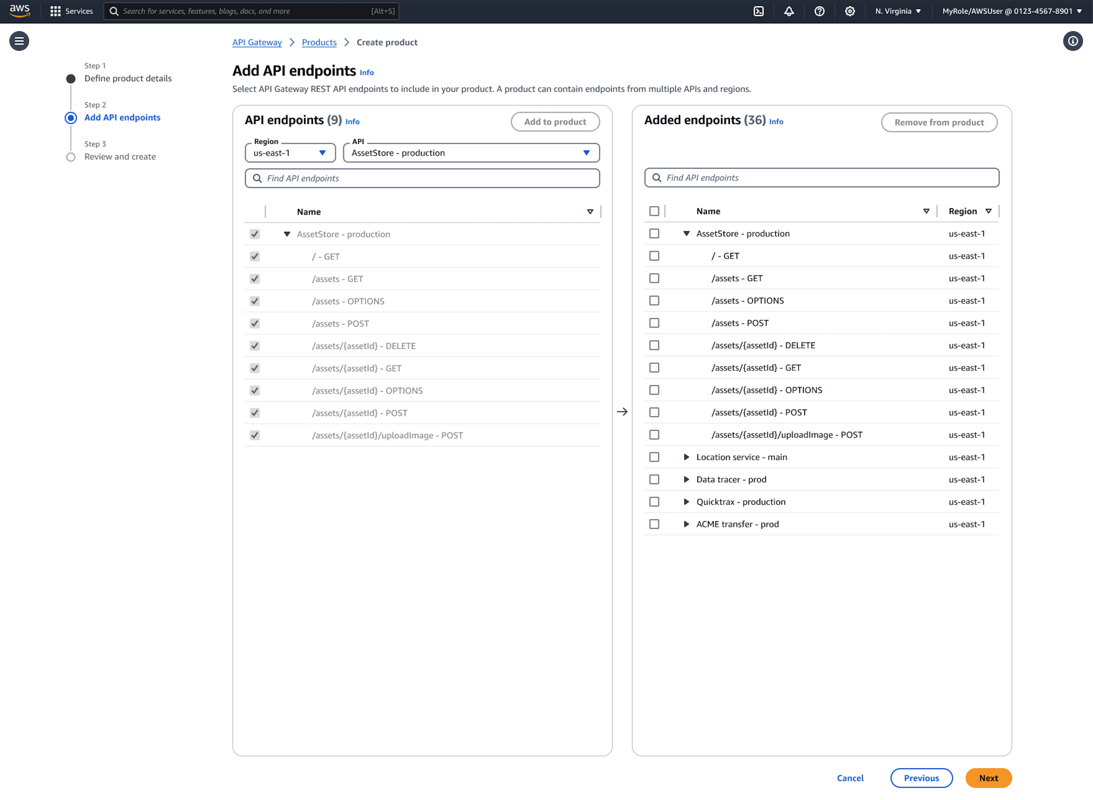
When using Bedrock AgentCore, you can operate MCP at scale through AgentCore Gateway. It provides an easy and secure way for developers to build, deploy, discover, and connect to remote tools like above at scale. With AgentCore Gateway, developers can convert APIs, Lambda functions, and existing services into Model Context Protocol (MCP)-compatible tools and make them available to agents through Gateway endpoints with just a few lines of code.
Monitoring and observability
Observability is essential when running AI agents. Beyond traditional metrics such as uptime and latency, agentic systems introduce new telemetry dimensions, such as LLM latency, token consumption, and tracing reasoning cycles. These new metrics are essential for understanding both the performance and cost of your agentic systems.
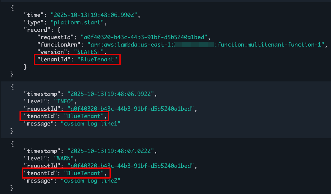
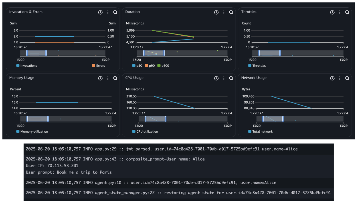
When deploying agents using AWS services such as Bedrock AgentCore, Lambda, or ECS, you inherit the built-in observability capabilities, such as seamless integration with Amazon CloudWatch for metrics, logs, and distributed tracing. This simplifies tracking invocation counts, errors, request duration, and concurrency, as shown in the following figure – essential for operating reliable and scalable agentic applications.

In addition, the Strands Agents SDK provides built-in agent observability features. It uses OpenTelemetry (OTEL) to automatically trace each agent interaction, including spans for LLM calls, tool usage, and context updates. It also exports detailed metrics such as token counts, tool execution times, and decision cycle durations. These metrics can be sent to any OTEL-compatible backend, giving you deep, real-time visibility into how your agents reason, act, and adapt. The following snippet shows built-in token usage metrics:
{
  "accumulated_usage": {
    "inputTokens": 1539,
    "outputTokens": 122,
    "totalTokens": 1661
  },
  "average_cycle_time": 0.881234884262085,
  "total_cycles": 2,
  "total_duration": 1.881234884262085,
  ... redacted ...
}
Learn more about observability and evaluation of Strands agents from this sample code.
When using Bedrock AgentCore, the AgentCore Observability primitive helps you to log and capture metrics and traceability from other AgentCore primitives like runtime, memory, and gateway, as described in this tutorial.
Security considerations
You should build secure communication and access controls layers deploying AI agents that integrate with remote MCP servers. All client-server interactions should be encrypted using TLS, ideally with mutual TLS for bidirectional authentication. Access to tools should be validated through authorization checks with fine-grained permissions to enforce least privilege access. Deploying MCP servers behind an API Gateway provides additional security layers like DDoS protection, WAF, and centralized authentication. Use API Gateway logging capabilities to capture caller identity and execution outcomes. Using trusted, versioned MCP repositories helps protect against supply chain attacks and ensures consistent tool governance across teams. Protocols such as MCP are evolving rapidly, you should always use the most recent versions to minimize potential security vulnerabilities risk.
In addition, you should leverage security best practices described in the AWS Well-Architected Framework Security Pillar, such as enforcing strict IAM role scoping, integrating with identity providers for user context, encrypting all data in transit and at rest, and using VPC endpoints and PrivateLink to limit network exposure. To protect against prompt injection attacks, sanitize inputs, and ensure you maintain comprehensive audit logs for compliance and governance.
Sample project
Follow instructions in this GitHub repo to deploy a sample project implementing the practices described in this post using the AWS Serverless compute. The repo includes a travel agent implemented with Strands Agents SDK and a remote MCP server, both running as Lambda functions.
Conclusion
Agentic AI moves beyond simple prompt-response interactions to enable dynamic, goal-driven workflows. In this post, you learned how to build scalable, production-ready agents on AWS using the Strands Agents SDK and serverless services such as Lambda and Amazon ECS.
By externalizing state, integrating authentication, and adding observability, agents can operate securely and at scale. With support for in-process and remote tools through the MCP, you can cleanly separate responsibilities and build composable, enterprise-ready systems. You can combine these patterns to deliver intelligent, adaptable AI agents that fit naturally into modern cloud and event-driven architectures.
Useful resources
To learn more about Serverless architectures see Serverless Land.


 Sairam Vangapally is a Data Engineer at Amazon with extensive experience architecting real-time, large-scale data platforms that power critical logistics operations across North America. He has led the design and deployment of end-to-end data pipelines, enabling high-throughput ingestion, transformation, and analytics at scale. He is passionate about building resilient data infrastructure and driving cross-functional collaboration to deliver solutions that accelerate operational insights and business impact.
 Nitin Goyal serves as a Data Engineering Manager in Amazon’s Sort Center organization, where he leads initiatives to optimize operational efficiency across North American facilities. With over nine years of tenure at Amazon spanning multiple teams, he specializes in architecting high-performance data systems, with particular emphasis on real-time streaming pipelines, artificial intelligence, and low-latency solutions. His expertise drives the development of sophisticated operational workflows that enhance sort center productivity and effectiveness.


