Tag Archives: DNS

Improving the Resiliency of Our Infrastructure DNS Zone

Post Syndicated from Ryan Timken original https://blog.cloudflare.com/improving-the-resiliency-of-our-infrastructure-dns-zone/

Improving the Resiliency of Our Infrastructure DNS Zone

In this blog post we will discuss how we made our infrastructure DNS zone more reliable by using multiple primary nameservers to leverage our own DNS product running on our edge as well as a third-party DNS provider.

Improving the Resiliency of Our Infrastructure DNS Zone

Authoritative Nameservers

You can think of an authoritative nameserver as the source of truth for the records of a given DNS zone. When a recursive resolver wants to look up a record, it will eventually need to talk to the authoritative nameserver(s) for the zone in question. If you’d like to read more on the topic, our learning center provides some additional information.

Here’s an example of our authoritative nameservers (replacing our actual domain with example.com):

~$ dig NS example.com +short
ns1.example.com.
ns2.example.com.
ns3.example.com.

As you can see, there are three nameservers listed. You’ll notice that the nameservers happen to reside in the same zone, but they don’t have to. Those three nameservers point to six anycasted IP addresses (3 x IPv4, 3 x IPv6) announced from our edge, comprising data centers from 200+ cities around the world.

The Problem

We store the hostnames for all of our machines, both the ones at the edge and the ones at core data centers, in a DNS zone we refer to as our infrastructure zone. By using our own DNS product to run our infrastructure zone, we get the reliability and performance of our Global Anycast Network. However, what would happen if those nameservers became unavailable due to an issue on our edge? Eventually DNS lookups would fail, as resolvers would not be able to connect to the only authoritative nameservers configured on the zone: the ones hosted on our edge. This is the main problem we set out to solve.

When an incident occurs, our engineering teams are busy investigating, debugging, and fixing the issue at hand. If they cannot resolve the hostnames of the infrastructure they need to use, it will lead to confusion and delays in resolving the incident.

Imagine you are part of a team tackling an incident. As you quickly begin to investigate, you try to connect to a specific machine to gather some debugging information, but you get a DNS resolution error. What now? You know you are using the right hostname. Is this a result of the incident at hand, some side effect, or is this completely unrelated? You need to keep investigating, so you try another way. Maybe you have memorized the IP address of the machine and you can connect. More likely, you ask another resolver which still has the answer in its cache and resolve the IP that way. One thing is certain, the extra “mini-debug” step costs you precious time and detracts from debugging the real root cause.

Unavailable nameservers and the problems they cause are not unique to Cloudflare, and are not specific to our use case. Even if we hosted our authoritative nameservers with a single external provider, they could also experience their own issues causing the nameservers to fail.

Within the DNS community it is always understood that the more diversity, the better. Some common methods include diversifying network/routing configurations and software choices between a standard primary/secondary setup. However, no matter how resilient the network or software stack is, a single authority is still responsible for the zone. Luckily, there are ways to solve this problem!

Our Solution: Multiple Primary Nameservers

Our solution was to set up our infrastructure zone with multiple primary nameservers. This type of setup is referred to as split authority, multi-primary, or primary/primary. This way, instead of using just one provider for our authoritative nameservers, we use two.

We added three nameservers from our additional provider to our zone at our registrar. Using multiple primaries allows changes to our zone at each provider, to be controlled separately and completely by us. Instead of using zone transfers to keep our zone in sync, we use OctoDNS to independently and simultaneously manage the zone at both providers. We’ll talk more about our use of OctoDNS in a bit.

This setup is similar to using a primary and secondary server. The main difference is that the nameservers operate independently from one another, and do not use the usual DNS AXFR/IXFR method to keep the zone up to date. If you’d like to learn more about this type of solution, here is a great blog post by Dina Kozlov, our Product Manager for DNS, about Secondary DNS.

The nameservers in our zone after adding an additional provider would look something like:

~$ dig NS example.com +short
ns1.example.com.
ns2.example.com.
ns3.example.com.
ns1.additional-provider.net.
ns2.additional-provider.net.
ns3.additional-provider.net.

Predictable Query Routing

Currently, we cannot coordinate which provider should be used when querying a record within the zone. Recursive resolvers have different methods of choosing which nameserver should be used when presented with multiple NS records. A popular choice is to use the server with the lowest RTT (round trip time). A great blog post from APNIC on recursive resolver authoritative nameserver selection can be consulted for a detailed explanation.

We needed to enforce specific routing decisions between the two authorities. Our requirement was for a weighted routing policy preferring Cloudflare based on availability checks for requests originating from our infrastructure servers. This reduces RTT, since the queries originate from the same servers hosting our nameservers in the same data center, and do not need to travel further to the external provider when all is well.

Our edge infrastructure servers are configured to use DNSDist as their primary system resolver. DNSDist load balances queries using multiple upstream recursive DNS servers (Unbound) in each data center to provide DNS resolution. This setup is used for internal DNS resolution only, and as such, it is independent from our authoritative DNS and public resolver 1.1.1.1 service.

Additionally, we modified our DNSDist configuration by adding two server pools for our infrastructure zone authoritative servers, and set up active checks with weighted routes to always use the Cloudflare pool when available. With the active checking and weighted routing in place, our queries are always routed internally when available. In the event of a Cloudflare authoritative DNS failure, DNSDist will route all requests for the zone to our external provider.

Maintaining Our Infrastructure DNS Zone

In addition to a more reliable infrastructure zone, we also wanted to further automate the provisioning of DNS records. We had been relying on an older manual tool that became quite slow handling our growing number of DNS records. In a nutshell, this tool queried our provisioning database to gather all of the machine names, and then created, deleted, or updated the required DNS records using the Cloudflare API. We had to run this tool whenever we provisioned or decommissioned  machines that serve our customers’ requests.

Part of the procedure for running this tool was to first run it in dry-run mode, and then paste the results for review in our team chat room. This review step ensured the changes the tool found were expected and safe to run, and it is something we want to keep as part of our plan to automate the process.

Here’s what the old tool looked like:

$ cf-provision update-example -l ${USER}@cloudflare.com -u
Running update-example.sh -t /var/tmp/cf-provision -l [email protected] -u
* Loading up possible records …

deleting: {"name":"node44.example.com","ttl":300, "type":"A","content":"192.0.2.2","proxied":false}
 rec_id:abcdefg
updating: { "name":"build-ts.example.com", "ttl":120, "type":"TXT", "content":"1596722274"} rec_id:123456 previous content: 1596712896

Result    : SUCCESS
Task      : BUILD
Dest dir  :
Started   : Thu, 06 Aug 2020 13:57:40 +0000
Finished  : Thu, 06 Aug 2020 13:58:16 +0000
Elapsed   : 36 secs
Records Changed In API  : 1 record(s) changed
Records Deleted In API  : 1 record(s) deleted

Zone Management with OctoDNS

As we mentioned earlier, when using a multi-primary setup for our infrastructure zone, we are required to maintain the zone data outside of traditional DNS replication. Before rolling out our own solution we wanted to see what was out there, and we stumbled upon OctoDNS, a project from GitHub. OctoDNS provides a set of tools that make it easy to manage your DNS records across multiple providers.

OctoDNS uses a pluggable architecture. This means we can rewrite our old script as a plugin (which is called a ‘source’), and use other existing provider plugins (called ‘providers’) to interact with both the Cloudflare and our other provider’s APIs. Should we decide to sync to more external DNS providers in the future, we would just need to add them to our OctoDNS configuration. This allows our records to stay up to date, and, as an added benefit, records OctoDNS doesn’t know about will be removed during operation (for example, changes made outside of OctoDNS). This ensures that manual changes do not diverge from what is present in the provisioning database.

Our goal was to keep the zone management workflow as simple as possible. At Cloudflare, we use TeamCity for CI/CD, and we realized that it could not only facilitate code builds of our OctoDNS implementation, but it could also be used to deploy the zone.

There are a number of benefits to using our existing TeamCity infrastructure.

  • Our DevTools team can reliably manage it as a service
  • It has granular permissions, which allow us to control who can deploy the changes
  • It provides storage of the logs for auditing
  • It allows easy rollback of zone revisions
  • It integrates easily with our chat ops workflow via Google Chat webhooks

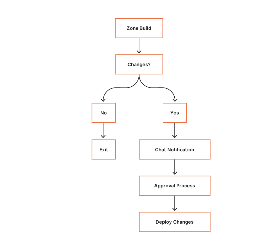
Below is a high-level overview of how we manage our zone through OctoDNS.

Improving the Resiliency of Our Infrastructure DNS Zone

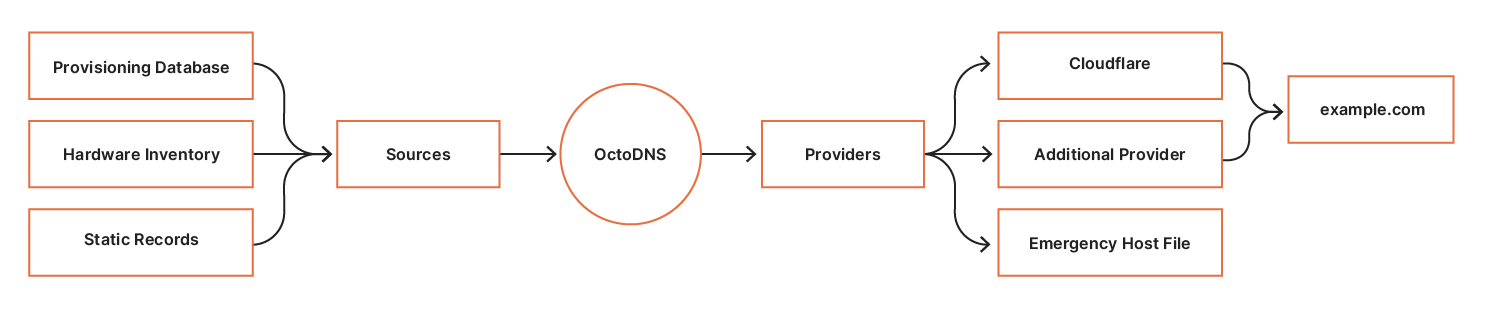
There are three steps in the workflow:

  1. Build – evaluate the sources and build the complete zone.
  2. Compare – parse the built zone and compare to the records on the providers. Changes found are sent to SRE for evaluation.
  3. Deploy – deploy the changes to the providers.
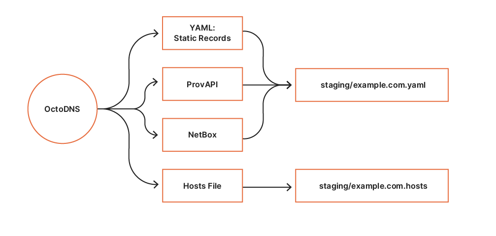
Step 1: Build

Sources
OctoDNS consumes data from our internal systems via custom source modules. So far, we have built two source modules for querying data:

  1. ProvAPI queries our internal provisioning API providing data center and node configuration.
  2. NetBox queries our internal NetBox deployment providing hardware metadata.

Additionally, static records are defined in a YAML file. These sources form the infrastructure zone source of truth.

Providers
The build process establishes a staging area per execution. The YAML provider builds a static YAML file containing the complete zone. The hosts file provider is used to generate an emergency hosts file for the zone. Contents from the staging area are revision controlled in CI, which allows us to easily deploy previous versions if required.

Improving the Resiliency of Our Infrastructure DNS Zone

Step 2: Compare

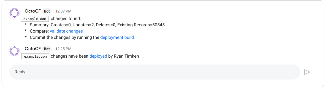
Following a successful zone build CI executes the compare build. During this phase, OctoDNS performs an octodns-sync in dry-run mode. The compare build consumes the staging YAML zone configuration, and compares the records against the records on our authoritative providers via their respective APIs. Any identified zone changes are parsed, and a summary line is generated and sent to the SRE Chat room for approval. SRE are automatically linked to the changes and associated CI build for deployment.

Improving the Resiliency of Our Infrastructure DNS Zone

Step 3: Deploy

The deployment CI build is access-controlled and scoped to the SRE group using our single sign-on provider. Following successful approval and peer review, an SRE can deploy the changes by executing the deploy build.

The deployment process is simple; consume the YAML zone data from our staging area and deploy the changes to the zone’s authoritative providers via ‘octodns-sync –doit’. The hosts file generated for the zone is packaged and deployed, to be used in the event of complete DNS failure.

Here’s an example of how the message looks. When the deploy is finished, the thread is updated to indicate which user initiated it.

Improving the Resiliency of Our Infrastructure DNS Zone

Future Improvements

In the future, we would like to automate the process further by reducing the need for approvals. There is usually no harm in adding new records, and it is done very often during the provisioning of new machines. Removing the need to approve those records would take out another step in the provisioning process, which is something we are always looking to optimize.

Introducing OctoDNS and an additional provider allowed us to make our infrastructure DNS zone more reliable and easier to manage. We can now easily include new sources of record data, with OctoDNS allowing us to focus more on new and exciting projects and less on managing DNS records.

SAD DNS Explained

Post Syndicated from Marek Vavruša original https://blog.cloudflare.com/sad-dns-explained/

SAD DNS Explained

This week, at the ACM CCS 2020 conference, researchers from UC Riverside and Tsinghua University announced a new attack against the Domain Name System (DNS) called SAD DNS (Side channel AttackeD DNS). This attack leverages recent features of the networking stack in modern operating systems (like Linux) to allow attackers to revive a classic attack category: DNS cache poisoning. As part of a coordinated disclosure effort earlier this year, the researchers contacted Cloudflare and other major DNS providers and we are happy to announce that 1.1.1.1 Public Resolver is no longer vulnerable to this attack.

In this post, we’ll explain what the vulnerability was, how it relates to previous attacks of this sort, what mitigation measures we have taken to protect our users, and future directions the industry should consider to prevent this class of attacks from being a problem in the future.

DNS Basics

The Domain Name System (DNS) is what allows users of the Internet to get around without memorizing long sequences of numbers. What’s often called the “phonebook of the Internet” is more like a helpful system of translators that take natural language domain names (like blog.cloudflare.com or gov.uk) and translate them into the native language of the Internet: IP addresses (like 192.0.2.254 or [2001:db8::cf]). This translation happens behind the scenes so that users only need to remember hostnames and don’t have to get bogged down with remembering IP addresses.

DNS is both a system and a protocol. It refers to the hierarchical system of computers that manage the data related to naming on a network and it refers to the language these computers use to speak to each other to communicate answers about naming. The DNS protocol consists of pairs of messages that correspond to questions and responses. Each DNS question (query) and answer (reply) follows a standard format and contains a set of parameters that contain relevant information such as the name of interest (such as blog.cloudflare.com) and the type of response record desired (such as A for IPv4 or AAAA for IPv6).

The DNS Protocol and Spoofing

These DNS messages are exchanged over a network between machines using a transport protocol. Originally, DNS used UDP, a simple stateless protocol in which messages are endowed with a set of metadata indicating a source port and a destination port. More recently, DNS has adapted to use more complex transport protocols such as TCP and even advanced protocols like TLS or HTTPS, which incorporate encryption and strong authentication into the mix (see Peter Wu’s blog post about DNS protocol encryption).

Still, the most common transport protocol for message exchange is UDP, which has the advantages of being fast, ubiquitous and requiring no setup. Because UDP is stateless, the pairing of a response to an outstanding query is based on two main factors: the source address and port pair, and information in the DNS message. Given that UDP is both stateless and unauthenticated, anyone, and not just the recipient, can send a response with a forged source address and port, which opens up a range of potential problems.

SAD DNS Explained
The blue portions contribute randomness

Since the transport layer is inherently unreliable and untrusted, the DNS protocol was designed with additional mechanisms to protect against forged responses. The first two bytes in the message form a message or transaction ID that must be the same in the query and response. When a DNS client sends a query, it will set the ID to a random value and expect the value in the response to match. This unpredictability introduces entropy into the protocol, which makes it less likely that a malicious party will be able to construct a valid DNS reply without first seeing the query. There are other potential variables to account for, like the DNS query name and query type are also used to pair query and response, but these are trivial to guess and don’t introduce an additional entropy.

Those paying close attention to the diagram may notice that the amount of entropy introduced by this measure is only around 16 bits, which means that there are fewer than a hundred thousand possibilities to go through to find the matching reply to a given query. More on this later.

The DNS Ecosystem

DNS servers fall into one of a few main categories: recursive resolvers (like 1.1.1.1 or 8.8.8.8), nameservers (like the DNS root servers or Cloudflare Authoritative DNS). There are also elements of the ecosystem that act as “forwarders” such as dnsmasq. In a typical DNS lookup, these DNS servers work together to complete the task of delivering the IP address for a specified domain to the client (the client is usually a stub resolver – a simple resolver built into an operating system). For more detailed information about the DNS ecosystem, take a look at our learning site. The SAD DNS attack targets the communication between recursive resolvers and nameservers.

Each of the participants in DNS (client, resolver, nameserver) uses the DNS protocol to communicate with each other. Most of the latest innovations in DNS revolve around upgrading the transport between users and recursive resolvers to use encryption. Upgrading the transport protocol between resolvers and authoritative servers is a bit more complicated as it requires a new discovery mechanism to instruct the resolver when to (and when not to use) a more secure channel.  Aside from a few examples like our work with Facebook to encrypt recursive-to-authoritative traffic with DNS-over-TLS, most of these exchanges still happen over UDP. This is the core issue that enables this new attack on DNS, and one that we’ve seen before.

Kaminsky’s Attack

Prior to 2008, recursive resolvers typically used a single open port (usually port 53) to send and receive messages to authoritative nameservers. This made guessing the source port trivial, so the only variable an attacker needed to guess to forge a response to a query was the 16-bit message ID. The attack Kaminsky described was relatively simple: whenever a recursive resolver queried the authoritative name server for a given domain, an attacker would flood the resolver with DNS responses for some or all of the 65 thousand or so possible message IDs. If the malicious answer with the right message ID arrived before the response from the authoritative server, then the DNS cache would be effectively poisoned, returning the attacker’s chosen answer instead of the real one for as long as the DNS response was valid (called the TTL, or time-to-live).

For popular domains, resolvers contact authoritative servers once per TTL (which can be as short as 5 minutes), so there are plenty of opportunities to mount this attack. Forwarders that cache DNS responses are also vulnerable to this type of attack.

SAD DNS Explained

In response to this attack, DNS resolvers started doing source port randomization and careful checking of the security ranking of cached data. To poison these updated resolvers, forged responses would not only need to guess the message ID, but they would also have to guess the source port, bringing the number of guesses from the tens of thousands to over a trillion. This made the attack effectively infeasible. Furthermore, the IETF published RFC 5452 on how to harden DNS from guessing attacks.

It should be noted that this attack did not work for DNSSEC-signed domains since their answers are digitally signed. However, even now in 2020, DNSSEC is far from universal.

Defeating Source Port Randomization with Fragmentation

Another way to avoid having to guess the source port number and message ID is to split the DNS response in two. As is often the case in computer security, old attacks become new again when attackers discover new capabilities. In 2012, researchers Amir Herzberg and Haya Schulman from Bar Ilan University discovered that it was possible for a remote attacker to defeat the protections provided by source port randomization. This new attack leveraged another feature of UDP: fragmentation. For a primer on the topic of UDP fragmentation, check out our previous blog post on the subject by Marek Majkowski.

The key to this attack is the fact that all the randomness that needs to be guessed in a DNS poisoning attack is concentrated at the beginning of the DNS message (UDP header and DNS header).If the UDP response packet (sometimes called a datagram) is split into two fragments, the first half containing the message ID and source port and the second containing part of the DNS response, then all an attacker needs to do is forge the second fragment and make sure that the fake second fragment arrives at the resolver before the true second fragment does. When a datagram is fragmented, each fragment is assigned a 16-bit IDs (called IP-ID), which is used to reassemble it at the other end of the connection. Since the second fragment only has the IP-ID as entropy (again, this is a familiar refrain in this area), this attack is feasible with a relatively small number of forged packets. The downside of this attack is the precondition that the response must be fragmented in the first place, and the fragment must be carefully altered to pass the original section counts and UDP checksum.

SAD DNS Explained

Also discussed in the original and follow-up papers is a method of forcing two remote servers to send packets between each other which are fragmented at an attacker-controlled point, making this attack much more feasible. The details are in the paper, but it boils down to the fact that the control mechanism for describing the maximum transmissible unit (MTU) between two servers — which determines at which point packets are fragmented — can be set via a forged UDP packet.

SAD DNS Explained

We explored this risk in a previous blog post in the context of certificate issuance last year when we introduced our multi-path DCV service, which mitigates this risk in the context of certificate issuance by making DNS queries from multiple vantage points. Nevertheless, fragmentation-based attacks are proving less and less effective as DNS providers move to eliminate support for fragmented DNS packets (one of the major goals of DNS Flag Day 2020).

Defeating Source Port Randomization via ICMP error messages

Another way to defeat the source port randomization is to use some measurable property of the server that makes the source port easier to guess. If the attacker could ask the server which port number is being used for a pending query, that would make the construction of a spoofed packet much easier. No such thing exists, but it turns out there is something close enough – the attacker can discover which ports are surely closed (and thus avoid having to send traffic). One such mechanism is the ICMP “port unreachable” message.

Let’s say the target receives a UDP datagram destined for its IP and some port, the datagram either ends up either being accepted and silently discarded by the application, or rejected because the port is closed. If the port is closed, or more importantly, closed to the IP address that the UDP datagram was sent from, the target will send back an ICMP message notifying the attacker that the port is closed. This is handy to know since the attacker now doesn’t have to bother trying to guess the pending message ID on this port and move to other ports. A single scan of the server effectively reduces the search space of valid UDP responses from 232 (over a trillion) to 217 (around a hundred thousand), at least in theory.

This trick doesn’t always work. Many resolvers use “connected” UDP sockets instead of “open” UDP sockets to exchange messages between the resolver and nameserver. Connected sockets are tied to the peer address and port on the OS layer, which makes it impossible for an attacker to guess which “connected” UDP sockets are established between the target and the victim, and since the attacker isn’t the victim, it can’t directly observe the outcome of the probe.

To overcome this, the researchers found a very clever trick: they leverage ICMP rate limits as a side channel to reveal whether a given port is open or not. ICMP rate limiting was introduced (somewhat ironically, given this attack) as a security feature to prevent a server from being used as an unwitting participant in a reflection attack. In broad terms, it is used to limit how many ICMP responses a server will send out in a given time period. Say an attacker wanted to scan 10,000 ports and sent a burst of 10,000 UDP packets to a server configured with an ICMP rate limit of 50 per second, then only the first 50 would get an ICMP “port unreachable” message in reply.

Rate limiting seems innocuous until you remember one of the core rules of data security: don’t let private information influence publicly measurable metrics. ICMP rate limiting violates this rule because the rate limiter’s behavior can be influenced by an attacker making guesses as to whether a “secret” port number is open or not.

don’t let private information influence publicly measurable metrics

An attacker wants to know whether the target has an open port, so it sends a spoofed UDP message from the authoritative server to that port. If the port is open, no ICMP reply is sent and the rate counter remains unchanged. If the port is inaccessible, then an ICMP reply is sent (back to the authoritative server, not to the attacker) and the rate is increased by one. Although the attacker doesn’t see the ICMP response, it has influenced the counter. The counter itself isn’t known outside the server, but whether it has hit the rate limit or not can be measured by any outside observer by sending a UDP packet and waiting for a reply. If an ICMP “port unreachable” reply comes back, the rate limit hasn’t been reached. No reply means the rate limit has been met. This leaks one bit of information about the counter to the outside observer, which in the end is enough to reveal the supposedly secret information (whether the spoofed request got through or not).

SAD DNS Explained
Diagram inspired by original paper‌‌

Concretely, the attack works as follows: the attacker sends a bunch (large enough to trigger the rate limiting) of probe messages to the target, but with a forged source address of the victim. In the case where there are no open ports in the probed set, the target will send out the same amount of ICMP “port unreachable” responses back to the victim and trigger the rate limit on outgoing ICMP messages. The attacker can now send an additional verification message from its own address and observe whether an ICMP response comes back or not. If it does then there was at least one port open in the set and the attacker can divide the set and try again, or do a linear scan by inserting the suspected port number into a set of known closed ports. Using this approach, the attacker can narrow down to the open ports and try to guess the message ID until it is successful or gives up, similarly to the original Kaminsky attack.

In practice there are some hurdles to successfully mounting this attack.

  • First, the target IP, or a set of target IPs must be discovered. This might be trivial in some cases – a single forwarder, or a fixed set of IPs that can be discovered by probing and observing attacker controlled zones, but more difficult if the target IPs are partitioned across zones as the attacker can’t see the resolver egress IP unless she can monitor the traffic for the victim domain.
  • The attack also requires a large enough ICMP outgoing rate limit in order to be able to scan with a reasonable speed. The scan speed is critical, as it must be completed while the query to the victim nameserver is still pending. As the scan speed is effectively fixed, the paper instead describes a method to potentially extend the window of opportunity by triggering the victim’s response rate limiting (RRL), a technique to protect against floods of forged DNS queries. This may work if the victim implements RRL and the target resolver doesn’t implement a retry over TCP (A Quantitative Study of the Deployment of DNS Rate Limiting shows about 16% of nameservers implement some sort of RRL).
  • Generally, busy resolvers will have ephemeral ports opening and closing, which introduces false positive open ports for the attacker, and ports open for different pending queries than the one being attacked.

We’ve implemented an additional mitigation to 1.1.1.1 to prevent message ID guessing – if the resolver detects an ID enumeration attempt, it will stop accepting any more guesses and switches over to TCP. This reduces the number of attempts for the attacker even if it guesses the IP address and port correctly, similarly to how the number of password login attempts is limited.

Outlook

Ultimately these are just mitigations, and the attacker might be willing to play the long game. As long as the transport layer is insecure and DNSSEC is not widely deployed, there will be different methods of chipping away at these mitigations.

It should be noted that trying to hide source IPs or open port numbers is a form of security through obscurity. Without strong cryptographic authentication, it will always be possible to use spoofing to poison DNS resolvers. The silver lining here is that DNSSEC exists, and is designed to protect against this type of attack, and DNS servers are moving to explore cryptographically strong transports such as TLS for communicating between resolvers and authoritative servers.

At Cloudflare, we’ve been helping to reduce the friction of DNSSEC deployment, while also helping to improve transport security in the long run. There is also an effort to increase entropy in DNS messages with RFC 7873 – Domain Name System (DNS) Cookies, and make DNS over TCP support mandatory RFC 7766 – DNS Transport over TCP – Implementation Requirements, with even more documentation around ways to mitigate this type of issue available in different places. All of these efforts are complementary, which is a good thing. The DNS ecosystem consists of many different parties and software with different requirements and opinions, as long as the operators support at least one of the preventive measures, these types of attacks will become more and more difficult.

If you are an operator of an authoritative DNS server, you should consider taking the following steps to protect yourself from this attack:

We’d like to thank the researchers for responsibly disclosing this attack and look forward to working with them in the future on efforts to strengthen the DNS.

Unwrap the SERVFAIL

Post Syndicated from Anbang Wen original https://blog.cloudflare.com/unwrap-the-servfail/

Unwrap the SERVFAIL

We recently released a new version of Cloudflare Resolver which adds a piece of information called “Extended DNS Errors” (EDE) along with the response code under certain circumstances. This will be helpful in tracing DNS resolution errors and figuring out what went wrong behind the scenes.

Unwrap the SERVFAIL
(image from: https://www.pxfuel.com/en/free-photo-expka)

A tight-lipped agent

The DNS protocol was designed to map domain names to IP addresses. To inform the client about the result of the lookup, the protocol has a 4 bit field, called response code/RCODE. The logic to serve a response might look something like this:

function lookup(domain) {
    ...
    switch result {
    case "No error condition":
        return NOERROR with client expected answer
    case "No record for the request type":
        return NOERROR
    case "The request domain does not exist":
        return NXDOMAIN
    case "Refuse to perform the specified operation for policy reasons":
        return REFUSE
    default("Server failure: unable to process this query due to a problem with the name server"):
        return SERVFAIL
    }
}

try {
    lookup(domain)
} catch {
    return SERVFAIL
}

Although the context hasn’t changed much, protocol extensions such as DNSSEC have been added, which makes the RCODE run out of space to express the server’s internal status. To keep backward compatibility, DNS servers have to squeeze various statuses into existing ones. This behavior could confuse the client, especially with the “catch-all” SERVFAIL: something went wrong but what exactly?

Most often, end users don’t talk to authoritative name servers directly, but use a stub and/or a recursive resolver as an agent to acquire the information it needs. When a user receives  SERVFAIL, the failure can be one of the following:

  • The stub resolver fails to send the request.
  • The stub resolver doesn’t get a response.
  • The recursive resolver, which the stub resolver sends its query to, is overloaded.
  • The recursive resolver is unable to communicate with upstream authoritative servers.
  • The recursive resolver fails to verify the DNSSEC chain.
  • The authoritative server takes too long to respond.

In such cases, it is nearly impossible for the user to know exactly what’s wrong. The resolver is usually the one to be blamed, because, as an agent, it fails to get back the answer, and doesn’t return a clear reason for the failure in the response.

Keep backward compatibility

It seems we need to return more information, but (there’s always a but) we also need to keep the behavior of existing clients unchanged.

One way is to extend the RCODE space, which came out with the Extension mechanisms for DNS or EDNS. It defines a 8 bit EXTENDED-RCODE, as high-order bits to current 4 bit RCODE. Together they make up a 12 bit integer. This changes the processing of RCODE, requires both client and server to fully support the logic unfortunately.

Another approach is to provide out-of-band data without touching the current RCODE. This is how Extended DNS Errors is defined. It introduces a new option to EDNS, containing an INFO-CODE to describe error details with an EXTRA-TEXT as an optional supplement. The option can be repeated as many times as needed, so it’s possible for the client to get a full error chain with detailed messages. The INFO-CODE is just something like RCODE, but is 16 bits wide, while the EXTRA-TEXT is an utf-8 encoded string. For example, let’s say a client sends a request to a resolver, and the requested domain has two name servers. The client may receive a SERVFAIL response with an OPT record (see below) which contains two extended errors, one from one of the authoritative servers that shows it’s not ready to serve, and the other from the resolver, showing it cannot connect to the other name server.

;; OPT PSEUDOSECTION:
; ...
; EDE: 14 (Not Ready)
; EDE: 23 (Network Error): (cannot reach upstream 192.0.2.1)
; ...

Google has something similar in their DoH JSON API, which provides diagnostic information in the “Comment” field.

Let’s dig into it

Our 1.1.1.1 service has an initial support of the draft version of Extended DNS Errors, while we are still trying to find the best practice. As we mentioned above, this is not a breaking change, and existing clients will not be affected. The additional options can be safely ignored without any problem, since the RCODE stays the same.

If you have a newer version of dig, you can simply check it out with a known problematic domain. As you can see, due to DNSSEC verification failing, the RCODE is still SERVFAIL, but the extended error shows the failure is “DNSSEC Bogus”.

$ dig @1.1.1.1 dnssec-failed.org

; <<>> DiG 9.16.4-Debian <<>> @1.1.1.1 dnssec-failed.org
; (1 server found)
;; global options: +cmd
;; Got answer:
;; ->>HEADER<<- opcode: QUERY, status: SERVFAIL, id: 1111
;; flags: qr rd ra; QUERY: 1, ANSWER: 0, AUTHORITY: 0, ADDITIONAL: 1

;; OPT PSEUDOSECTION:
; EDNS: version: 0, flags:; udp: 1232
; EDE: 6 (DNSSEC Bogus)
;; QUESTION SECTION:
;dnssec-failed.org.		IN	A

;; Query time: 111 msec
;; SERVER: 1.1.1.1#53(1.1.1.1)
;; WHEN: Wed Sep 01 00:00:00 PDT 2020
;; MSG SIZE  rcvd: 52

Note that Extended DNS Error relies on EDNS. So to be able to get one, the client needs to support EDNS, and needs to enable it in the request. At the time of writing this blog post, we see about 17% of queries that 1.1.1.1 received had EDNS enabled within a short time range. We hope this information will help you uncover the root cause of a SERVFAIL in the future.

DNS Flag Day 2020

Post Syndicated from Christian Elmerot original https://blog.cloudflare.com/dns-flag-day-2020/

DNS Flag Day 2020

DNS Flag Day 2020

October 1 was this year’s DNS Flag Day. Read on to find out all about DNS Flag Day and how it affects Cloudflare’s DNS services (hint: it doesn’t, we already did the work to be compliant).

What is DNS Flag Day?

DNS Flag Day is an initiative by several DNS vendors and operators to increase the compliance of implementations with DNS standards. The goal is to make DNS more secure, reliable and robust. Rather than a push for new features, DNS flag day is meant to ensure that workarounds for non-compliance can be reduced and a common set of functionalities can be established and relied upon.

Last year’s flag day was February 1, and it set forth that servers and clients must be able to properly handle the Extensions to DNS (EDNS0) protocol (first RFC about EDNS0 are from 1999 – RFC 2671). This way, by assuming clients have a working implementation of EDNS0, servers can resort to always sending messages as EDNS0. This is needed to support DNSSEC, the DNS security extensions. We were, of course, more than thrilled to support the effort, as we’re keen to push DNSSEC adoption forward .

DNS Flag Day 2020

The goal for this year’s flag day is to increase DNS messaging reliability by focusing on problems around IP fragmentation of DNS packets. The intention is to reduce DNS message fragmentation which continues to be a problem. We can do that by ensuring cleartext DNS messages sent over UDP are not too large, as large messages risk being fragmented during the transport. Additionally, when sending or receiving large DNS messages, we have the ability to do so over TCP.

Problem with DNS transport over UDP

A potential issue with sending DNS messages over UDP is that the sender has no indication of the recipient actually receiving the message. When using TCP, each packet being sent is acknowledged (ACKed) by the recipient, and the sender will attempt to resend any packets not being ACKed. UDP, although it may be faster than TCP, does not have the same mechanism of messaging reliability. Anyone still wishing to use UDP as their transport protocol of choice will have to implement this reliability mechanism in higher layers of the network stack. For instance, this is what is being done in QUIC, the new Internet transport protocol used by HTTP/3 that is built on top of UDP.

Even the earliest DNS standards (RFC 1035) specified the use of sending DNS messages over TCP as well as over UDP. Unfortunately, the choice of supporting TCP or not was up to the implementer/operator, and then firewalls were sometimes set to block DNS over TCP. More recent updates to RFC 1035, on the other hand, require that the DNS server is available to query using DNS over TCP.

DNS message fragmentation

Sending data over networks and the Internet is restricted to the limitation of how large each packet can be. Data is chopped up into a stream of packets, and sized to adhere to the Maximum Transmission Unit (MTU) of the network. MTU is typically 1500 bytes for IPv4 and, in the case of IPv6, the minimum is 1280 bytes. Subtracting both the IP header size (IPv4 20 bytes/IPv6 40 bytes) and the UDP protocol header size (8 bytes) from the MTU, we end up with a maximum DNS message size of 1472 bytes for IPv4 and 1232 bytes in order for a message to fit within a single packet. If the message is any larger than that, it will have to be fragmented into more packets.

Sending large messages causes them to get fragmented into more than one pack. This is not a problem with TCP transports since each packet is ACK:ed to ensure proper delivery. However, the same does not hold true when sending large DNS messages over UDP. For many intents and purposes, UDP has been treated as a second-class citizen to TCP as far as network routing is concerned. It is quite common to see UDP packet fragments being dropped by routers and firewalls, potentially causing parts of a message to be lost. To avoid fragmentation over UDP it is better to truncate the DNS message and set the Truncation Flag in the DNS response. This tells the recipient that more data is available if the query is retried over TCP.

DNS Flag Day 2020 wants to ensure that DNS message fragmentation does not happen. When larger DNS messages need to be sent, we need to ensure it can be done reliably over TCP.

DNS servers need to support DNS message transport over TCP in order to be compliant with this year’s flag day. Also, DNS messages sent over UDP must never exceed the limit over which they risk being fragmented.

Cloudflare authoritative DNS and 1.1.1.1

We fully support the DNS Flag Day initiative, as it aims to make DNS more reliable and robust, and it ensures a common set of features for the DNS community to evolve on. In the DNS ecosystem, we are as much a client as we are a provider. When we perform DNS lookups on behalf of our customers and users, we rely on other providers to follow standards and be compliant. When they are not, and we can’t work around the issues, it leads to problems resolving names and reaching resources.

Both our public resolver 1.1.1.1 as well as our authoritative DNS service, set and enforce reasonable limits on DNS message sizes when sent over UDP. Of course, both services are available over TCP. If you’re already using Cloudflare, there is nothing you need to do but to keep using our DNS services! We will continually work on improving DNS.

Oh, and you can test your domain on the DNS Flag Day site: https://dnsflagday.net/2020/

Secondary DNS – Deep Dive

Post Syndicated from Alex Fattouche original https://blog.cloudflare.com/secondary-dns-deep-dive/

How Does Secondary DNS Work?

Secondary DNS - Deep Dive

If you already understand how Secondary DNS works, please feel free to skip this section. It does not provide any Cloudflare-specific information.

Secondary DNS has many use cases across the Internet; however, traditionally, it was used as a synchronized backup for when the primary DNS server was unable to respond to queries. A more modern approach involves focusing on redundancy across many different nameservers, which in many cases broadcast the same anycasted IP address.

Secondary DNS involves the unidirectional transfer of DNS zones from the primary to the Secondary DNS server(s). One primary can have any number of Secondary DNS servers that it must communicate with in order to keep track of any zone updates. A zone update is considered a change in the contents of a  zone, which ultimately leads to a Start of Authority (SOA) serial number increase. The zone’s SOA serial is one of the key elements of Secondary DNS; it is how primary and secondary servers synchronize zones. Below is an example of what an SOA record might look like during a dig query.

example.com	3600	IN	SOA	ashley.ns.cloudflare.com. dns.cloudflare.com. 
2034097105  // Serial
10000 // Refresh
2400 // Retry
604800 // Expire
3600 // Minimum TTL

Each of the numbers is used in the following way:

  1. Serial – Used to keep track of the status of the zone, must be incremented at every change.
  2. Refresh – The maximum number of seconds that can elapse before a Secondary DNS server must check for a SOA serial change.
  3. Retry – The maximum number of seconds that can elapse before a Secondary DNS server must check for a SOA serial change, after previously failing to contact the primary.
  4. Expire – The maximum number of seconds that a Secondary DNS server can serve stale information, in the event the primary cannot be contacted.
  5. Minimum TTL – Per RFC 2308, the number of seconds that a DNS negative response should be cached for.

Using the above information, the Secondary DNS server stores an SOA record for each of the zones it is tracking. When the serial increases, it knows that the zone must have changed, and that a zone transfer must be initiated.  

Serial Tracking

Serial increases can be detected in the following ways:

  1. The fastest way for the Secondary DNS server to keep track of a serial change is to have the primary server NOTIFY them any time a zone has changed using the DNS protocol as specified in RFC 1996, Secondary DNS servers will instantly be able to initiate a zone transfer.
  2. Another way is for the Secondary DNS server to simply poll the primary every “Refresh” seconds. This isn’t as fast as the NOTIFY approach, but it is a good fallback in case the notifies have failed.

One of the issues with the basic NOTIFY protocol is that anyone on the Internet could potentially notify the Secondary DNS server of a zone update. If an initial SOA query is not performed by the Secondary DNS server before initiating a zone transfer, this is an easy way to perform an amplification attack. There is two common ways to prevent anyone on the Internet from being able to NOTIFY Secondary DNS servers:

  1. Using transaction signatures (TSIG) as per RFC 2845. These are to be placed as the last record in the extra records section of the DNS message. Usually the number of extra records (or ARCOUNT) should be no more than two in this case.
  2. Using IP based access control lists (ACL). This increases security but also prevents flexibility in server location and IP address allocation.

Generally NOTIFY messages are sent over UDP, however TCP can be used in the event the primary server has reason to believe that TCP is necessary (i.e. firewall issues).

Zone Transfers

In addition to serial tracking, it is important to ensure that a standard protocol is used between primary and Secondary DNS server(s), to efficiently transfer the zone. DNS zone transfer protocols do not attempt to solve the confidentiality, authentication and integrity triad (CIA); however, the use of TSIG on top of the basic zone transfer protocols can provide integrity and authentication. As a result of DNS being a public protocol, confidentiality during the zone transfer process is generally not a concern.

Authoritative Zone Transfer (AXFR)

AXFR is the original zone transfer protocol that was specified in RFC 1034 and RFC 1035 and later further explained in RFC 5936. AXFR is done over a TCP connection because a reliable protocol is needed to ensure packets are not lost during the transfer. Using this protocol, the primary DNS server will transfer all of the zone contents to the Secondary DNS server, in one connection, regardless of the serial number. AXFR is recommended to be used for the first zone transfer, when none of the records are propagated, and IXFR is recommended after that.

Incremental Zone Transfer (IXFR)

IXFR is the more sophisticated zone transfer protocol that was specified in RFC 1995. Unlike the AXFR protocol, during an IXFR, the primary server will only send the secondary server the records that have changed since its current version of the zone (based on the serial number). This means that when a Secondary DNS server wants to initiate an IXFR, it sends its current serial number to the primary DNS server. The primary DNS server will then format its response based on previous versions of changes made to the zone. IXFR messages must obey the following pattern:

  1. Current latest SOA
  2. Secondary server current SOA
  3. DNS record deletions
  4. Secondary server current SOA + changes
  5. DNS record additions
  6. Current latest SOA

Steps 2,3,4,5,6 can be repeated any number of times, as each of those represents one change set of deletions and additions, ultimately leading to a new serial.

IXFR can be done over UDP or TCP, but again TCP is generally recommended to avoid packet loss.

How Does Secondary DNS Work at Cloudflare?

The DNS team loves microservice architecture! When we initially implemented Secondary DNS at Cloudflare, it was done using Mesos Marathon. This allowed us to separate each of our services into several different marathon apps, individually scaling apps as needed. All of these services live in our core data centers. The following services were created:

  1. Zone Transferer – responsible for attempting IXFR, followed by AXFR if IXFR fails.
  2. Zone Transfer Scheduler – responsible for periodically checking zone SOA serials for changes.
  3. Rest API – responsible for registering new zones and primary nameservers.

In addition to the marathon apps, we also had an app external to the cluster:

  1. Notify Listener – responsible for listening for notifies from primary servers and telling the Zone Transferer to initiate an AXFR/IXFR.

Each of these microservices communicates with the others through Kafka.

Secondary DNS - Deep Dive
Figure 1: Secondary DNS Microservice Architecture‌‌

Once the zone transferer completes the AXFR/IXFR, it then passes the zone through to our zone builder, and finally gets pushed out to our edge at each of our 200 locations.

Although this current architecture worked great in the beginning, it left us open to many vulnerabilities and scalability issues down the road. As our Secondary DNS product became more popular, it was important that we proactively scaled and reduced the technical debt as much as possible. As with many companies in the industry, Cloudflare has recently migrated all of our core data center services to Kubernetes, moving away from individually managed apps and Marathon clusters.

What this meant for Secondary DNS is that all of our Marathon-based services, as well as our NOTIFY Listener, had to be migrated to Kubernetes. Although this long migration ended up paying off, many difficult challenges arose along the way that required us to come up with unique solutions in order to have a seamless, zero downtime migration.

Challenges When Migrating to Kubernetes

Although the entire DNS team agreed that kubernetes was the way forward for Secondary DNS, it also introduced several challenges. These challenges arose from a need to properly scale up across many distributed locations while also protecting each of our individual data centers. Since our core does not rely on anycast to automatically distribute requests, as we introduce more customers, it opens us up to denial-of-service attacks.

The two main issues we ran into during the migration were:

  1. How do we create a distributed and reliable system that makes use of kubernetes principles while also making sure our customers know which IPs we will be communicating from?
  2. When opening up a public-facing UDP socket to the Internet, how do we protect ourselves while also preventing unnecessary spam towards primary nameservers?.

Issue 1:

As was previously mentioned, one form of protection in the Secondary DNS protocol is to only allow certain IPs to initiate zone transfers. There is a fine line between primary servers allow listing too many IPs and them having to frequently update their IP ACLs. We considered several solutions:

  1. Open source k8s controllers
  2. Altering Network Address Translation(NAT) entries
  3. Do not use k8s for zone transfers
  4. Allowlist all Cloudflare IPs and dynamically update
  5. Proxy egress traffic

Ultimately we decided to proxy our egress traffic from k8s, to the DNS primary servers, using static proxy addresses. Shadowsocks-libev was chosen as the SOCKS5 implementation because it is fast, secure and known to scale. In addition, it can handle both UDP/TCP and IPv4/IPv6.

Secondary DNS - Deep Dive
Figure 2: Shadowsocks proxy Setup

The partnership of k8s and Shadowsocks combined with a large enough IP range brings many benefits:

  1. Horizontal scaling
  2. Efficient load balancing
  3. Primary server ACLs only need to be updated once
  4. It allows us to make use of kubernetes for both the Zone Transferer and the Local ShadowSocks Proxy.
  5. Shadowsocks proxy can be reused by many different Cloudflare services.

Issue 2:

The Notify Listener requires listening on static IPs for NOTIFY Messages coming from primary DNS servers. This is mostly a solved problem through the use of k8s services of type loadbalancer, however exposing this service directly to the Internet makes us uneasy because of its susceptibility to attacks. Fortunately DDoS protection is one of Cloudflare’s strengths, which lead us to the likely solution of dogfooding one of our own products, Spectrum.

Spectrum provides the following features to our service:

  1. Reverse proxy TCP/UDP traffic
  2. Filter out Malicious traffic
  3. Optimal routing from edge to core data centers
  4. Dual Stack technology
Secondary DNS - Deep Dive
Figure 3: Spectrum interaction with Notify Listener

Figure 3 shows two interesting attributes of the system:

  1. Spectrum <-> k8s IPv4 only:
  2. This is because our custom k8s load balancer currently only supports IPv4; however, Spectrum has no issue terminating the IPv6 connection and establishing a new IPv4 connection.
  3. Spectrum <-> k8s routing decisions based of L4 protocol:
  4. This is because k8s only supports one of TCP/UDP/SCTP per service of type load balancer. Once again, spectrum has no issues proxying this correctly.

One of the problems with using a L4 proxy in between services is that source IP addresses get changed to the source IP address of the proxy (Spectrum in this case). Not knowing the source IP address means we have no idea who sent the NOTIFY message, opening us up to attack vectors. Fortunately, Spectrum’s proxy protocol feature is capable of adding custom headers to TCP/UDP packets which contain source IP/Port information.

As we are using miekg/dns for our Notify Listener, adding proxy headers to the DNS NOTIFY messages would cause failures in validation at the DNS server level. Alternatively, we were able to implement custom read and write decorators that do the following:

  1. Reader: Extract source address information on inbound NOTIFY messages. Place extracted information into new DNS records located in the additional section of the message.
  2. Writer: Remove additional records from the DNS message on outbound NOTIFY replies. Generate a new reply using proxy protocol headers.

There is no way to spoof these records, because the server only permits two extra records, one of which is the optional TSIG. Any other records will be overwritten.

Secondary DNS - Deep Dive
Figure 4: Proxying Records Between Notifier and Spectrum‌‌

This custom decorator approach abstracts the proxying away from the Notify Listener through the use of the DNS protocol.  

Although knowing the source IP will block a significant amount of bad traffic, since NOTIFY messages can use both UDP and TCP, it is prone to IP spoofing. To ensure that the primary servers do not get spammed, we have made the following additions to the Zone Transferer:

  1. Always ensure that the SOA has actually been updated before initiating a zone transfer.
  2. Only allow at most one working transfer and one scheduled transfer per zone.

Additional Technical Challenges

Zone Transferer Scheduling

As shown in figure 1, there are several ways of sending Kafka messages to the Zone Transferer in order to initiate a zone transfer. There is no benefit in having a large backlog of zone transfers for the same zone. Once a zone has been transferred, assuming no more changes, it does not need to be transferred again. This means that we should only have at most one transfer ongoing, and one scheduled transfer at the same time, for any zone.

If we want to limit our number of scheduled messages to one per zone, this involves ignoring Kafka messages that get sent to the Zone Transferer. This is not as simple as ignoring specific messages in any random order. One of the benefits of Kafka is that it holds on to messages until the user actually decides to acknowledge them, by committing that messages offset. Since Kafka is just a queue of messages, it has no concept of order other than first in first out (FIFO). If a user is capable of reading from the Kafka topic concurrently, it is entirely possible that a message in the middle of the queue be committed before a message at the end of the queue.

Most of the time this isn’t an issue, because we know that one of the concurrent readers has read the message from the end of the queue and is processing it. There is one Kubernetes-related catch to this issue, though: pods are ephemeral. The kube master doesn’t care what your concurrent reader is doing, it will kill the pod and it’s up to your application to handle it.

Consider the following problem:

Secondary DNS - Deep Dive
Figure 5: Kafka Partition‌‌
  1. Read offset 1. Start transferring zone 1.
  2. Read offset 2. Start transferring zone 2.
  3. Zone 2 transfer finishes. Commit offset 2, essentially also marking offset 1.
  4. Restart pod.
  5. Read offset 3 Start transferring zone 3.

If these events happen, zone 1 will never be transferred. It is important that zones stay up to date with the primary servers, otherwise stale data will be served from the Secondary DNS server. The solution to this problem involves the use of a list to track which messages have been read and completely processed. In this case, when a zone transfer has finished, it does not necessarily mean that the kafka message should be immediately committed. The solution is as follows:

  1. Keep a list of Kafka messages, sorted based on offset.
  2. If finished transfer, remove from list:
  3. If the message is the oldest in the list, commit the messages offset.
Secondary DNS - Deep Dive
Figure 6: Kafka Algorithm to Solve Message Loss

This solution is essentially soft committing Kafka messages, until we can confidently say that all other messages have been acknowledged. It’s important to note that this only truly works in a distributed manner if the Kafka messages are keyed by zone id, this will ensure the same zone will always be processed by the same Kafka consumer.

Life of a Secondary DNS Request

Although Cloudflare has a large global network, as shown above, the zone transferring process does not take place at each of the edge datacenter locations (which would surely overwhelm many primary servers), but rather in our core data centers. In this case, how do we propagate to our edge in seconds? After transferring the zone, there are a couple more steps that need to be taken before the change can be seen at the edge.

  1. Zone Builder – This interacts with the Zone Transferer to build the zone according to what Cloudflare edge understands. This then writes to Quicksilver, our super fast, distributed KV store.
  2. Authoritative Server – This reads from Quicksilver and serves the built zone.
Secondary DNS - Deep Dive
Figure 7: End to End Secondary DNS‌‌

What About Performance?

At the time of writing this post, according to dnsperf.com, Cloudflare leads in global performance for both Authoritative and Resolver DNS. Here, Secondary DNS falls under the authoritative DNS category here. Let’s break down the performance of each of the different parts of the Secondary DNS pipeline, from the primary server updating its records, to them being present at the Cloudflare edge.

  1. Primary Server to Notify Listener – Our most accurate measurement is only precise to the second, but we know UDP/TCP communication is likely much faster than that.
  2. NOTIFY to Zone Transferer – This is negligible
  3. Zone Transferer to Primary Server – 99% of the time we see ~800ms as the average latency for a zone transfer.
Secondary DNS - Deep Dive
Figure 8: Zone XFR latency

4. Zone Transferer to Zone Builder – 99% of the time we see ~10ms to build a zone.

Secondary DNS - Deep Dive
Figure 9: Zone Build time

5. Zone Builder to Quicksilver edge: 95% of the time we see less than 1s propagation.

Secondary DNS - Deep Dive
Figure 10: Quicksilver propagation time

End to End latency: less than 5 seconds on average. Although we have several external probes running around the world to test propagation latencies, they lack precision due to their sleep intervals, location, provider and number of zones that need to run. The actual propagation latency is likely much lower than what is shown in figure 10. Each of the different colored dots is a separate data center location around the world.

Secondary DNS - Deep Dive
Figure 11: End to End Latency

An additional test was performed manually to get a real world estimate, the test had the following attributes:

Primary server: NS1
Number of records changed: 1
Start test timer event: Change record on NS1
Stop test timer event: Observe record change at Cloudflare edge using dig
Recorded timer value: 6 seconds

Conclusion

Cloudflare serves 15.8 trillion DNS queries per month, operating within 100ms of 99% of the Internet-connected population. The goal of Cloudflare operated Secondary DNS is to allow our customers with custom DNS solutions, be it on-premise or some other DNS provider, to be able to take advantage of Cloudflare’s DNS performance and more recently, through Secondary Override, our proxying and security capabilities too. Secondary DNS is currently available on the Enterprise plan, if you’d like to take advantage of it, please let your account team know. For additional documentation on Secondary DNS, please refer to our support article.