Tag Archives: Growth

Growth Engineering at Netflix- Creating a Scalable Offers Platform

Post Syndicated from Netflix Technology Blog original https://netflixtechblog.com/growth-engineering-at-netflix-creating-a-scalable-offers-platform-69330136dd87

by Eric Eiswerth

Background

Netflix has been offering streaming video-on-demand (SVOD) for over 10 years. Throughout that time we’ve primarily relied on 3 plans (Basic, Standard, & Premium), combined with the 30-day free trial to drive global customer acquisition. The world has changed a lot in this time. Competition for people’s leisure time has increased, the device ecosystem has grown phenomenally, and consumers want to watch premium content whenever they want, wherever they are, and on whatever device they prefer. We need to be constantly adapting and innovating as a result of this change.

The Growth Engineering team is responsible for executing growth initiatives that help us anticipate and adapt to this change. In particular, it’s our job to design and build the systems and protocols that enable customers from all over the world to sign up for Netflix with the plan features and incentives that best suit their needs. For more background on Growth Engineering and the signup funnel, please have a look at our previous blog post that covers the basics. Alternatively, here’s a quick review of what the typical user journey for a signup looks like:

Signup Funnel Dynamics

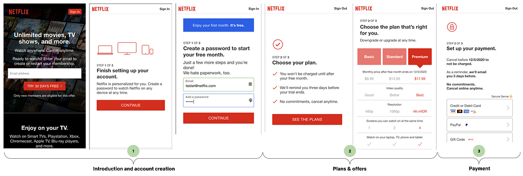
There are 3 steps in a basic Netflix signup. We refer to these steps that comprise a user journey as a signup flow. Each step of the flow serves a distinct purpose.

  1. Introduction and account creation
    Highlight our value propositions and begin the account creation process.
  2. Plans & offers
    Highlight the various types of Netflix plans, along with any potential offers.
  3. Payment
    Highlight the various payment options we have so customers can choose what suits their needs best.

The primary focus for the remainder of this post will be step 2: plans & offers. In particular, we’ll define plans and offers, review the legacy architecture and some of its shortcomings, and dig into our new architecture and some of its advantages.

Plans & Offers

Definitions

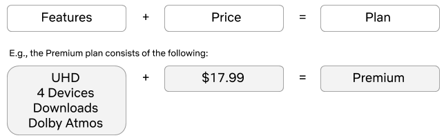
Let’s define what a plan and an offer is at Netflix. A plan is essentially a set of features with a price.

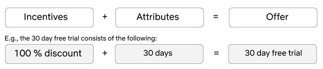
An offer is an incentive that typically involves a monetary discount or superior product features for a limited amount of time. Broadly speaking, an offer consists of one or more incentives and a set of attributes.

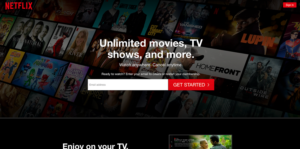
When we merge these two concepts together and present them to the customer, we have the plan selection page (shown above). Here, you can see that we have 3 plans and a 30-day free trial offer, regardless of which plan you choose. Let’s take a deeper look at the architecture, protocols, and systems involved.

Legacy Architecture

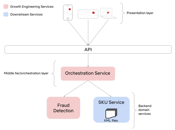
As previously mentioned, Netflix has had a relatively static set of plans and offers since the inception of streaming. As a result of this simple product offering, the architecture was also quite straightforward. It consisted of a small set of XML files that were loaded at runtime and stored in local memory. This was a perfectly sufficient design for many years. However, there are some downsides as the company continues to grow and the product continues to evolve. To name a few:

  • Updating XML files is error-prone and manual in nature.
  • A full deployment of the service is required whenever the XML files are updated.
  • Updating the XML files requires engaging domain experts from the backend engineering team that owns these files. This pulls them away from other business-critical work and can be a distraction.
  • A flat domain object structure that resulted in client-side logic in order to extract relevant plan and offer information in order to render the UI. For example, consider the data structure for a 30 day free trial on the Basic plan.
{
"offerId": 123,
"planId": 111,
"price": "$8.99",
"hasSD": true,
"hasHD": false,
"hasFreeTrial": true,
etc…
}
  • As the company matures and our product offering adapts to our global audience, all of the above issues are exacerbated further.

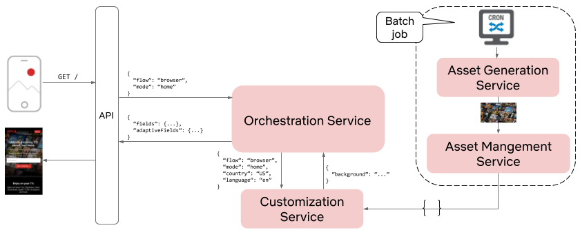
Below is a visual representation of the various systems involved in retrieving plan and offer data. Moving forward, we’ll refer to the combination of plan and offer data simply as SKU (Stock Keeping Unit) data.

New Architecture

If you recall from our previous blog post, Growth Engineering owns the business logic and protocols that allow our UI partners to build lightweight and flexible applications for almost any platform. This implies that the presentation layer should be void of any business logic and should simply be responsible for rendering data that is passed to it. In order to accomplish this we have designed a microservice architecture that emphasizes the Separation of Concerns design principle. Consider the updated system interaction diagram below:

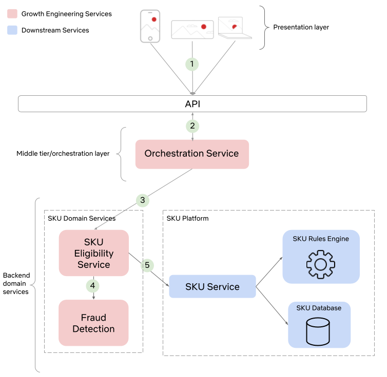
There are 2 noteworthy changes that are worth discussing further. First, notice the presence of a dedicated SKU Eligibility Service. This service contains specialized business logic that used to be part of the Orchestration Service. By migrating this logic to a new microservice we simplify the Orchestration Service, clarify ownership over the domain, and unlock new use cases since it is now possible for other services not shown in this diagram to also consume eligible SKU data.

Second, notice that the SKU Service has been extended to a platform, which now leverages a rules engine and SKU catalog DB. This platform unlocks tremendous business value since product-oriented teams are now free to use the platform to experiment with different product offerings for our global audience, with little to no code changes required. This means that engineers can spend less time doing tedious work and more time designing creative solutions to better prepare us for future needs. Let’s take a deeper look at the role of each service involved in retrieving SKU data, starting from the visitor’s device and working our way down the stack.

Step 1 — Device sends a request for the plan selection page
As discussed in our previous Growth Engineering blog post, we use a custom JSON protocol between our client UIs and our middle-tier Orchestration Service. An example of what this protocol might look like for a browser request to retrieve the plan selection page shown above might look as follows:

GET /plans
{
“flow”: “browser”,
“mode”: “planSelection”
}

As you can see, there are 2 critical pieces of information in this request:

  • Flow — The flow is a way to identify the platform. This allows the Orchestration Service to route the request to the appropriate platform-specific request handling logic.
  • Mode — This is essentially the name of the page being requested.

Given the flow and mode, the Orchestration Service can then process the request.

Step 2 — Request is routed to the Orchestration Service for processing
The Orchestration Service is responsible for validating upstream requests, orchestrating calls to downstream services, and composing JSON responses during a signup flow. For this particular request the Orchestration Service needs to retrieve the SKU data from the SKU Eligibility Service and build the JSON response that can be consumed by the UI layer.

The JSON response for this request might look something like below. Notice the difference in data structures from the legacy implementation. This new contextual representation facilitates greater reuse, as well as potentially supporting offers other than a 30 day free trial:

{
“flow”: “browser”,
“mode”: “planSelection”,
“fields”: {
“skus”: [
{
“id”: 123,
“incentives”: [“FREE_TRIAL”],
“plan”: {
“name”: “Basic”,
“quality”: “SD”,
“price” : “$8.99”,
...
}
...
},
{
“id”: 456,
“incentives”: [“FREE_TRIAL”],
“plan”: {
“name”: “Standard”,
“quality”: “HD”,
“price” : “$13.99”,
...
}
...
},
{
“id”: 789,
“incentives”: [“FREE_TRIAL”],
“plan”: {
“name”: “Premium”,
“quality”: “UHD”,
“price” : “$17.99”,
...
}
...
}
],
“selectedSku”: {
“type”: “Numeric”,
“value”: 789
}
"nextAction": {
"type": "Action"
"withFields": [
"selectedSku"
]
}
}
}

As you can see, the response contains a list of SKUs, the selected SKU, and an action. The action corresponds to the button on the page and the withFields specify which fields the server expects to have sent back when the button is clicked.

Step 3 & 4 — Determine eligibility and retrieve eligible SKUs from SKU Eligibility Service
Netflix is a global company and we often have different SKUs in different regions. This means we need to distinguish between availability of SKUs and eligibility for SKUs. You can think of eligibility as something that is applied at the user level, while availability is at the country level. The SKU Platform contains the global set of SKUs and as a result, is said to control the availability of SKUs. Eligibility for SKUs is determined by the SKU Eligibility Service. This distinction creates clear ownership boundaries and enables the Growth Engineering team to focus on surfacing the correct SKUs for our visitors.

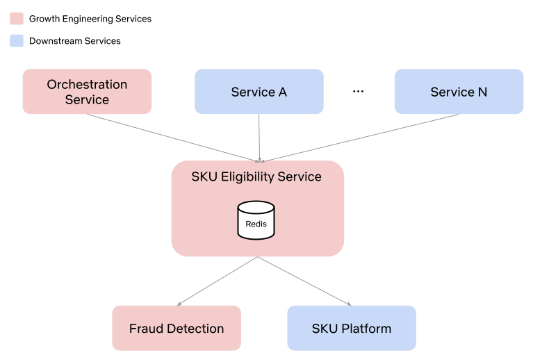
This centralization of eligibility logic in the SKU Eligibility Service also enables innovation in different parts of the product that have traditionally been ignored. Different services can now interface directly with the SKU Eligibility Service in order to retrieve SKU data.

Step 5 — Retrieve eligible SKUs from SKU Platform
The SKU Platform consists of a rules engine, a database, and application logic. The database contains the plans, prices and offers. The rules engine provides a means to extract available plans and offers when certain conditions within a rule match. Let’s consider a simple example where we attempt to retrieve offers in the US.

Keeping the Separation of Concerns in mind, notice that the SKU Platform has only one core responsibility. It is responsible for managing all Netflix SKUs. It provides access to these SKUs via a simple API that takes customer context and attempts to match it against the set of SKU rules. SKU eligibility is computed upstream and is treated just as any other condition would be in the SKU ruleset. By not coupling the concepts of eligibility and availability into a single service, we enable increased developer productivity since each team is able to focus on their core competencies and any change in eligibility does not affect the SKU Platform. One of the core tenets of a platform is the ability to support self-service. This negates the need to engage the backend domain experts for every desired change. The SKU Platform supports this via lightweight configuration changes to rules that do not require a full deployment. The next step is to invest further into self-service and support rule changes via a SKU UI. Stay tuned for more details on this, as well as more details on the internals of the new SKU Platform in one of our upcoming blog posts.

Conclusion

This work was a large cross-functional effort. We rebuilt our offers and plans from the ground up. It resulted in systems changes, as well as interaction changes between teams. Where there was once ambiguity, we now have clearly defined ownership over SKU availability and eligibility. We are now capable of introducing new plans and offers in various markets around the globe in order to meet our customer’s needs, with minimal engineering effort.

Let’s review some of the advantages the new architecture has over the legacy implementation. To name a few:

  • Domain objects that have a more reusable and extensible “shape”. This shape facilitates code reuse at the UI layer as well as the service layers.
  • A SKU Platform that enables product innovation with minimal engineering involvement. This means engineers can focus on more challenging and creative solutions for other problems. It also means fewer engineering teams are required to support initiatives in this space.
  • Configuration instead of code for updating SKU data, which improves innovation velocity.
  • Lower latency as a result of fewer service calls, which means fewer errors for our visitors.

The world is constantly changing. Device capabilities continue to improve. How, when, and where people want to be entertained continues to evolve. With these types of continued investments in infrastructure, the Growth Engineering team is able to build a solid foundation for future innovations that will allow us to continue to deliver the best possible experience for our members.

Join Growth Engineering and help us build the next generation of services that will allow the next 200 million subscribers to experience the joy of Netflix.


Growth Engineering at Netflix- Creating a Scalable Offers Platform was originally published in Netflix TechBlog on Medium, where people are continuing the conversation by highlighting and responding to this story.

Growth Engineering at Netflix — Automated Imagery Generation

Post Syndicated from Netflix Technology Blog original https://netflixtechblog.com/growth-engineering-at-netflix-automated-imagery-generation-5a105fd51569

Growth Engineering at Netflix — Automated Imagery Generation

by Eric Eiswerth

Background

There’s a good chance you’ve probably visited the Netflix homepage. In the Growth Engineering team, we refer to this as the top of the signup funnel. For more background on the signup funnel and Growth Engineering’s role in the signup funnel, please read our initial post on the topic: Growth Engineering at Netflix — Accelerating Innovation. The primary focus of this post will be the top of the signup funnel. In particular, the Netflix homepage:

As discussed in our previous post, Growth Engineering owns the business logic and protocols that allow our UI partners to build lightweight and flexible applications for almost any platform. In some cases, like the homepage, this even involves providing appropriate imagery (e.g., the background image shown above). In this post, we’ll take a deep dive into the journey of content-based imagery on the Netflix homepage.

Motivation

At Netflix we do one thing — entertainment — and we aim to do it really well. We live and breathe TV shows and films, and we want everyone to be able to enjoy them too. That’s why we aspire to have best in class stories, across genres and believe people should have access to new voices, cultures and perspectives. The member-focused teams at Netflix are responsible for making sure the member experience is relevant and personalized, ensuring that this content is shown to the right people at the right time. But what about non-members; those who are simply interested in signing up for Netflix, how should we highlight our content and convey our value propositions to them?

The Solution

The main mechanism for highlighting our content in the signup flow is through content-based imagery. Before designing a solution it’s important to understand the main product requirements for such a feature:

  • The content needs to be new, relevant, and regional (not all countries have the same catalogue).
  • The artwork needs to appeal to a broader audience. The non-member homepage serves a very broad audience and is not personalized to the extent of the member experience.
  • The imagery needs to be localized.
  • We need to be able to easily determine what imagery is present for a given platform, region, and language.
  • The homepage needs to load in a reasonable amount of time, even in poor network conditions.

Unpacking Product Requirements

Given the scale we require and the product requirements listed above, there are a number of technical requirements:

  • A list of titles for the asset, in some order.
  • Ensure the titles are appropriate for a broad audience, which means all titles need to be tagged with metadata.
  • Localized images for each of the titles.
  • Different assets for different device types and screen sizes.
  • Server-generated assets, since client-side generation would require the retrieval of many individual images, which would increase latency and time-to-render.
  • To reduce latency, assets should be generated in an offline fashion and not in real time.
  • The assets need to be compressed, without reducing quality significantly.
  • The assets will need to be stored somewhere and we’ll need to generate URLs for each of them.
  • We’ll need to figure out how to provide the correct asset URL for a given request.
  • We’ll need to build a search index so that the assets can be searchable.

Given this set of requirements, we can effectively break this work down into 3 functional buckets:

The Design

For our design, we decided to build 3 separate microservices, mapping to the aforementioned functional buckets. Let’s take a look at each of these services in turn.

Asset Generation

The Asset Generation Service is responsible for generating groups of assets. We call these groups of assets, asset groups. Each request will generate a single asset group that will contain one or more assets. To support the demands of our stakeholders we designed a Domain Specific Language (DSL) that we call an asset generation recipe. An asset generation request contains a recipe. Below is an example of a simple recipe:

{
"titleIds": [12345, 23456, 34567, …],
"countries": [“US”],
"type": “perspective”, // this is the design of the asset
"rows": 10, // the number of rows and columns can control density
"cols": 15,
"padding": 10, // padding between individual images
"columnOffsets": [0, 0, 0, 0…], // the y-offset for each column
"rowOffsets": [0, -100, 0, -100, …], // the x-offset for each row
"size": [1920, 1080] // size in pixels
}

This recipe can then be issued via an HTTP POST request to the Asset Generation Service. The recipe can then be translated into ImageMagick commands that can do the heavy lifting. At a high level, the following diagram captures the necessary steps required to build an asset.

Generating a single localized asset is a big achievement, but we still need to store the asset somewhere and have the ability to search for it. This requires an asset storage solution.

Asset Storage

We refer to asset storage and management simply as asset management. We felt it would be beneficial to create a separate microservice for asset management for 2 reasons. First, asset generation is CPU intensive and bursty. We can leverage high performance VMs in AWS to generate the assets. We can scale up when generation is occurring and scale down when there is no batch in the queue. However, it would be cost-inefficient to leverage this same hardware for lightweight and more consistent traffic patterns that an asset management service requires.

Let’s take a look at the internals of the Asset Management Service.

At this point we’ve laid out all the details in order to generate a content-based asset and have it stored as part of an asset group, which is persisted and indexed. The next thing to consider is, how do we retrieve an asset in real time and surface it on the Netflix homepage?

If you recall in our previous blog post, Growth Engineering owns a service called the Orchestration Service. It is a mid-tier service that emits a custom JSON data structure that contains fields that are consumed by the UI. The UI can then use these fields to control the presentation in the UI layer. There are two approaches for adding fields to the Orchestration Service’s response. First, the fields can be coded by hand. Second, fields can be added via configuration via a service we call the Customization Service. Since assets will need to be periodically refreshed and we want this process to be entirely automated, it makes sense to pursue the configuration-based approach. To accomplish this, the Asset Management Service needs to translate an asset group into a rule definition for the Customization Service.

Customization Service

Let’s review the Orchestration Service and introduce the Customization Service. The Orchestration Service emits fields in response to upstream requests. For the homepage, there are typically only a small number of fields provided by the Orchestration Service. The following fields are supplied by application code. For example:

{
“fields”: {
“email” : {
“type”: “StringField”,
“value”: “”
},
“nextAction”: {
“type”: “Action”,
“withFields” [“email”]
}
}
}

The Orchestration Service also supports fields supplied by configuration. We call these adaptive fields. Adaptive fields are provided by the Customization Service. The Customization Service is a rules engine that emits the adaptive fields. For example, a rule to provide the background image for the homepage in the en-US locale would look as follows:

{
“country”: “US”,
“language”: “en”,
“platform”: “browser”,
“resolution”: “high”
}

The corresponding payload for such a rule might look as follows:

{
“backgroundImage”: “https://cdn.netflix.com/bgimageurl.jpg”
}

Bringing this all together, the response from the Orchestration Service would now look as follows:

{
“fields”: {
“email” : {
“type”: “StringField”,
“value”: “”
},
“nextAction”: {
“type”: “Action”,
“withFields” [“email”]
}
},
“adaptiveFields”: {
“backgroundImage”: “https://cdn.netflix.com/bgimageurl.jpg”
}
}

At this point, we are now able to generate an asset, persist it, search it, and generate customization rules for it. The generated rules then enable us to return a particular asset for a particular request. Let’s put it all together and review the system interaction diagram.

We now have all the pieces in place to automatically generate artwork and have that artwork appear on the Netflix homepage for a given request. At least one open question remains, how can we scale asset generation?

Scaling Asset Generation

Arguably, there are a number of approaches that could be used to scale asset generation. We decided to opt for an all-or-nothing approach. Meaning, all assets for a given recipe need to be generated as a single asset group. This enables smooth rollback in case of any errors. Additionally, asset generation is CPU intensive and each recipe can produce 1000s of assets as a result of the number of platform, region, and language permutations. Even with high performance VMs, generating 1000s of assets can take a long time. As a result, we needed to find a way to distribute asset generation across multiple VMs. Here’s what the final architecture looked like.

Briefly, let’s review the steps:

  1. The batch process is initiated by a cron job. The job executes a script that contains an asset generation recipe.
  2. The Asset Generation Service receives the request and creates asset generation tasks that can be distributed across any number of Asset Generation Worker nodes. One of the nodes is elected as the leader via Zookeeper. Its job is to coordinate asset generation across the other workers and ensure all assets get generated.
  3. Once the primary worker node has all the assets, it creates an asset group in the Asset Management Service. The Asset Management Service persists, indexes, and uploads the assets to the CDN.
  4. Finally, the Asset Management Service creates rules from the asset group and pushes the rules to the Customization Service. Once the data is published in the Customization Service, the Orchestration Service can supply the correct URLs in its JSON response by invoking the Customization Service with a request context that matches a given set of rules.

Conclusion

Automated asset generation has proven to be an extremely valuable investment. It is low-maintenance, high-leverage, and has allowed us to experiment with a variety of different types of assets on different platforms and on different parts of the product. This project was technically challenging and highly rewarding, both to the engineers involved in the project, and to the business. The Netflix homepage has come a long way over the last several years.

We’re hiring! Join Growth Engineering and help us build the future of Netflix.


Growth Engineering at Netflix — Automated Imagery Generation was originally published in Netflix TechBlog on Medium, where people are continuing the conversation by highlighting and responding to this story.

Secondary DNS – Deep Dive

Post Syndicated from Alex Fattouche original https://blog.cloudflare.com/secondary-dns-deep-dive/

How Does Secondary DNS Work?

Secondary DNS - Deep Dive

If you already understand how Secondary DNS works, please feel free to skip this section. It does not provide any Cloudflare-specific information.

Secondary DNS has many use cases across the Internet; however, traditionally, it was used as a synchronized backup for when the primary DNS server was unable to respond to queries. A more modern approach involves focusing on redundancy across many different nameservers, which in many cases broadcast the same anycasted IP address.

Secondary DNS involves the unidirectional transfer of DNS zones from the primary to the Secondary DNS server(s). One primary can have any number of Secondary DNS servers that it must communicate with in order to keep track of any zone updates. A zone update is considered a change in the contents of a  zone, which ultimately leads to a Start of Authority (SOA) serial number increase. The zone’s SOA serial is one of the key elements of Secondary DNS; it is how primary and secondary servers synchronize zones. Below is an example of what an SOA record might look like during a dig query.

example.com	3600	IN	SOA	ashley.ns.cloudflare.com. dns.cloudflare.com. 
2034097105  // Serial
10000 // Refresh
2400 // Retry
604800 // Expire
3600 // Minimum TTL

Each of the numbers is used in the following way:

  1. Serial – Used to keep track of the status of the zone, must be incremented at every change.
  2. Refresh – The maximum number of seconds that can elapse before a Secondary DNS server must check for a SOA serial change.
  3. Retry – The maximum number of seconds that can elapse before a Secondary DNS server must check for a SOA serial change, after previously failing to contact the primary.
  4. Expire – The maximum number of seconds that a Secondary DNS server can serve stale information, in the event the primary cannot be contacted.
  5. Minimum TTL – Per RFC 2308, the number of seconds that a DNS negative response should be cached for.

Using the above information, the Secondary DNS server stores an SOA record for each of the zones it is tracking. When the serial increases, it knows that the zone must have changed, and that a zone transfer must be initiated.  

Serial Tracking

Serial increases can be detected in the following ways:

  1. The fastest way for the Secondary DNS server to keep track of a serial change is to have the primary server NOTIFY them any time a zone has changed using the DNS protocol as specified in RFC 1996, Secondary DNS servers will instantly be able to initiate a zone transfer.
  2. Another way is for the Secondary DNS server to simply poll the primary every “Refresh” seconds. This isn’t as fast as the NOTIFY approach, but it is a good fallback in case the notifies have failed.

One of the issues with the basic NOTIFY protocol is that anyone on the Internet could potentially notify the Secondary DNS server of a zone update. If an initial SOA query is not performed by the Secondary DNS server before initiating a zone transfer, this is an easy way to perform an amplification attack. There is two common ways to prevent anyone on the Internet from being able to NOTIFY Secondary DNS servers:

  1. Using transaction signatures (TSIG) as per RFC 2845. These are to be placed as the last record in the extra records section of the DNS message. Usually the number of extra records (or ARCOUNT) should be no more than two in this case.
  2. Using IP based access control lists (ACL). This increases security but also prevents flexibility in server location and IP address allocation.

Generally NOTIFY messages are sent over UDP, however TCP can be used in the event the primary server has reason to believe that TCP is necessary (i.e. firewall issues).

Zone Transfers

In addition to serial tracking, it is important to ensure that a standard protocol is used between primary and Secondary DNS server(s), to efficiently transfer the zone. DNS zone transfer protocols do not attempt to solve the confidentiality, authentication and integrity triad (CIA); however, the use of TSIG on top of the basic zone transfer protocols can provide integrity and authentication. As a result of DNS being a public protocol, confidentiality during the zone transfer process is generally not a concern.

Authoritative Zone Transfer (AXFR)

AXFR is the original zone transfer protocol that was specified in RFC 1034 and RFC 1035 and later further explained in RFC 5936. AXFR is done over a TCP connection because a reliable protocol is needed to ensure packets are not lost during the transfer. Using this protocol, the primary DNS server will transfer all of the zone contents to the Secondary DNS server, in one connection, regardless of the serial number. AXFR is recommended to be used for the first zone transfer, when none of the records are propagated, and IXFR is recommended after that.

Incremental Zone Transfer (IXFR)

IXFR is the more sophisticated zone transfer protocol that was specified in RFC 1995. Unlike the AXFR protocol, during an IXFR, the primary server will only send the secondary server the records that have changed since its current version of the zone (based on the serial number). This means that when a Secondary DNS server wants to initiate an IXFR, it sends its current serial number to the primary DNS server. The primary DNS server will then format its response based on previous versions of changes made to the zone. IXFR messages must obey the following pattern:

  1. Current latest SOA
  2. Secondary server current SOA
  3. DNS record deletions
  4. Secondary server current SOA + changes
  5. DNS record additions
  6. Current latest SOA

Steps 2,3,4,5,6 can be repeated any number of times, as each of those represents one change set of deletions and additions, ultimately leading to a new serial.

IXFR can be done over UDP or TCP, but again TCP is generally recommended to avoid packet loss.

How Does Secondary DNS Work at Cloudflare?

The DNS team loves microservice architecture! When we initially implemented Secondary DNS at Cloudflare, it was done using Mesos Marathon. This allowed us to separate each of our services into several different marathon apps, individually scaling apps as needed. All of these services live in our core data centers. The following services were created:

  1. Zone Transferer – responsible for attempting IXFR, followed by AXFR if IXFR fails.
  2. Zone Transfer Scheduler – responsible for periodically checking zone SOA serials for changes.
  3. Rest API – responsible for registering new zones and primary nameservers.

In addition to the marathon apps, we also had an app external to the cluster:

  1. Notify Listener – responsible for listening for notifies from primary servers and telling the Zone Transferer to initiate an AXFR/IXFR.

Each of these microservices communicates with the others through Kafka.

Secondary DNS - Deep Dive
Figure 1: Secondary DNS Microservice Architecture‌‌

Once the zone transferer completes the AXFR/IXFR, it then passes the zone through to our zone builder, and finally gets pushed out to our edge at each of our 200 locations.

Although this current architecture worked great in the beginning, it left us open to many vulnerabilities and scalability issues down the road. As our Secondary DNS product became more popular, it was important that we proactively scaled and reduced the technical debt as much as possible. As with many companies in the industry, Cloudflare has recently migrated all of our core data center services to Kubernetes, moving away from individually managed apps and Marathon clusters.

What this meant for Secondary DNS is that all of our Marathon-based services, as well as our NOTIFY Listener, had to be migrated to Kubernetes. Although this long migration ended up paying off, many difficult challenges arose along the way that required us to come up with unique solutions in order to have a seamless, zero downtime migration.

Challenges When Migrating to Kubernetes

Although the entire DNS team agreed that kubernetes was the way forward for Secondary DNS, it also introduced several challenges. These challenges arose from a need to properly scale up across many distributed locations while also protecting each of our individual data centers. Since our core does not rely on anycast to automatically distribute requests, as we introduce more customers, it opens us up to denial-of-service attacks.

The two main issues we ran into during the migration were:

  1. How do we create a distributed and reliable system that makes use of kubernetes principles while also making sure our customers know which IPs we will be communicating from?
  2. When opening up a public-facing UDP socket to the Internet, how do we protect ourselves while also preventing unnecessary spam towards primary nameservers?.

Issue 1:

As was previously mentioned, one form of protection in the Secondary DNS protocol is to only allow certain IPs to initiate zone transfers. There is a fine line between primary servers allow listing too many IPs and them having to frequently update their IP ACLs. We considered several solutions:

  1. Open source k8s controllers
  2. Altering Network Address Translation(NAT) entries
  3. Do not use k8s for zone transfers
  4. Allowlist all Cloudflare IPs and dynamically update
  5. Proxy egress traffic

Ultimately we decided to proxy our egress traffic from k8s, to the DNS primary servers, using static proxy addresses. Shadowsocks-libev was chosen as the SOCKS5 implementation because it is fast, secure and known to scale. In addition, it can handle both UDP/TCP and IPv4/IPv6.

Secondary DNS - Deep Dive
Figure 2: Shadowsocks proxy Setup

The partnership of k8s and Shadowsocks combined with a large enough IP range brings many benefits:

  1. Horizontal scaling
  2. Efficient load balancing
  3. Primary server ACLs only need to be updated once
  4. It allows us to make use of kubernetes for both the Zone Transferer and the Local ShadowSocks Proxy.
  5. Shadowsocks proxy can be reused by many different Cloudflare services.

Issue 2:

The Notify Listener requires listening on static IPs for NOTIFY Messages coming from primary DNS servers. This is mostly a solved problem through the use of k8s services of type loadbalancer, however exposing this service directly to the Internet makes us uneasy because of its susceptibility to attacks. Fortunately DDoS protection is one of Cloudflare’s strengths, which lead us to the likely solution of dogfooding one of our own products, Spectrum.

Spectrum provides the following features to our service:

  1. Reverse proxy TCP/UDP traffic
  2. Filter out Malicious traffic
  3. Optimal routing from edge to core data centers
  4. Dual Stack technology
Secondary DNS - Deep Dive
Figure 3: Spectrum interaction with Notify Listener

Figure 3 shows two interesting attributes of the system:

  1. Spectrum <-> k8s IPv4 only:
  2. This is because our custom k8s load balancer currently only supports IPv4; however, Spectrum has no issue terminating the IPv6 connection and establishing a new IPv4 connection.
  3. Spectrum <-> k8s routing decisions based of L4 protocol:
  4. This is because k8s only supports one of TCP/UDP/SCTP per service of type load balancer. Once again, spectrum has no issues proxying this correctly.

One of the problems with using a L4 proxy in between services is that source IP addresses get changed to the source IP address of the proxy (Spectrum in this case). Not knowing the source IP address means we have no idea who sent the NOTIFY message, opening us up to attack vectors. Fortunately, Spectrum’s proxy protocol feature is capable of adding custom headers to TCP/UDP packets which contain source IP/Port information.

As we are using miekg/dns for our Notify Listener, adding proxy headers to the DNS NOTIFY messages would cause failures in validation at the DNS server level. Alternatively, we were able to implement custom read and write decorators that do the following:

  1. Reader: Extract source address information on inbound NOTIFY messages. Place extracted information into new DNS records located in the additional section of the message.
  2. Writer: Remove additional records from the DNS message on outbound NOTIFY replies. Generate a new reply using proxy protocol headers.

There is no way to spoof these records, because the server only permits two extra records, one of which is the optional TSIG. Any other records will be overwritten.

Secondary DNS - Deep Dive
Figure 4: Proxying Records Between Notifier and Spectrum‌‌

This custom decorator approach abstracts the proxying away from the Notify Listener through the use of the DNS protocol.  

Although knowing the source IP will block a significant amount of bad traffic, since NOTIFY messages can use both UDP and TCP, it is prone to IP spoofing. To ensure that the primary servers do not get spammed, we have made the following additions to the Zone Transferer:

  1. Always ensure that the SOA has actually been updated before initiating a zone transfer.
  2. Only allow at most one working transfer and one scheduled transfer per zone.

Additional Technical Challenges

Zone Transferer Scheduling

As shown in figure 1, there are several ways of sending Kafka messages to the Zone Transferer in order to initiate a zone transfer. There is no benefit in having a large backlog of zone transfers for the same zone. Once a zone has been transferred, assuming no more changes, it does not need to be transferred again. This means that we should only have at most one transfer ongoing, and one scheduled transfer at the same time, for any zone.

If we want to limit our number of scheduled messages to one per zone, this involves ignoring Kafka messages that get sent to the Zone Transferer. This is not as simple as ignoring specific messages in any random order. One of the benefits of Kafka is that it holds on to messages until the user actually decides to acknowledge them, by committing that messages offset. Since Kafka is just a queue of messages, it has no concept of order other than first in first out (FIFO). If a user is capable of reading from the Kafka topic concurrently, it is entirely possible that a message in the middle of the queue be committed before a message at the end of the queue.

Most of the time this isn’t an issue, because we know that one of the concurrent readers has read the message from the end of the queue and is processing it. There is one Kubernetes-related catch to this issue, though: pods are ephemeral. The kube master doesn’t care what your concurrent reader is doing, it will kill the pod and it’s up to your application to handle it.

Consider the following problem:

Secondary DNS - Deep Dive
Figure 5: Kafka Partition‌‌
  1. Read offset 1. Start transferring zone 1.
  2. Read offset 2. Start transferring zone 2.
  3. Zone 2 transfer finishes. Commit offset 2, essentially also marking offset 1.
  4. Restart pod.
  5. Read offset 3 Start transferring zone 3.

If these events happen, zone 1 will never be transferred. It is important that zones stay up to date with the primary servers, otherwise stale data will be served from the Secondary DNS server. The solution to this problem involves the use of a list to track which messages have been read and completely processed. In this case, when a zone transfer has finished, it does not necessarily mean that the kafka message should be immediately committed. The solution is as follows:

  1. Keep a list of Kafka messages, sorted based on offset.
  2. If finished transfer, remove from list:
  3. If the message is the oldest in the list, commit the messages offset.
Secondary DNS - Deep Dive
Figure 6: Kafka Algorithm to Solve Message Loss

This solution is essentially soft committing Kafka messages, until we can confidently say that all other messages have been acknowledged. It’s important to note that this only truly works in a distributed manner if the Kafka messages are keyed by zone id, this will ensure the same zone will always be processed by the same Kafka consumer.

Life of a Secondary DNS Request

Although Cloudflare has a large global network, as shown above, the zone transferring process does not take place at each of the edge datacenter locations (which would surely overwhelm many primary servers), but rather in our core data centers. In this case, how do we propagate to our edge in seconds? After transferring the zone, there are a couple more steps that need to be taken before the change can be seen at the edge.

  1. Zone Builder – This interacts with the Zone Transferer to build the zone according to what Cloudflare edge understands. This then writes to Quicksilver, our super fast, distributed KV store.
  2. Authoritative Server – This reads from Quicksilver and serves the built zone.
Secondary DNS - Deep Dive
Figure 7: End to End Secondary DNS‌‌

What About Performance?

At the time of writing this post, according to dnsperf.com, Cloudflare leads in global performance for both Authoritative and Resolver DNS. Here, Secondary DNS falls under the authoritative DNS category here. Let’s break down the performance of each of the different parts of the Secondary DNS pipeline, from the primary server updating its records, to them being present at the Cloudflare edge.

  1. Primary Server to Notify Listener – Our most accurate measurement is only precise to the second, but we know UDP/TCP communication is likely much faster than that.
  2. NOTIFY to Zone Transferer – This is negligible
  3. Zone Transferer to Primary Server – 99% of the time we see ~800ms as the average latency for a zone transfer.
Secondary DNS - Deep Dive
Figure 8: Zone XFR latency

4. Zone Transferer to Zone Builder – 99% of the time we see ~10ms to build a zone.

Secondary DNS - Deep Dive
Figure 9: Zone Build time

5. Zone Builder to Quicksilver edge: 95% of the time we see less than 1s propagation.

Secondary DNS - Deep Dive
Figure 10: Quicksilver propagation time

End to End latency: less than 5 seconds on average. Although we have several external probes running around the world to test propagation latencies, they lack precision due to their sleep intervals, location, provider and number of zones that need to run. The actual propagation latency is likely much lower than what is shown in figure 10. Each of the different colored dots is a separate data center location around the world.

Secondary DNS - Deep Dive
Figure 11: End to End Latency

An additional test was performed manually to get a real world estimate, the test had the following attributes:

Primary server: NS1
Number of records changed: 1
Start test timer event: Change record on NS1
Stop test timer event: Observe record change at Cloudflare edge using dig
Recorded timer value: 6 seconds

Conclusion

Cloudflare serves 15.8 trillion DNS queries per month, operating within 100ms of 99% of the Internet-connected population. The goal of Cloudflare operated Secondary DNS is to allow our customers with custom DNS solutions, be it on-premise or some other DNS provider, to be able to take advantage of Cloudflare’s DNS performance and more recently, through Secondary Override, our proxying and security capabilities too. Secondary DNS is currently available on the Enterprise plan, if you’d like to take advantage of it, please let your account team know. For additional documentation on Secondary DNS, please refer to our support article.