Security and network administrators can control outbound access from a virtual private cloud (VPC) to specific destinations by using a service like AWS Network Firewall. You can use stateful rule groups to control outbound access to domains for HTTP and HTTPS by default in Network Firewall. In this post, we’ll walk you through how to accomplish this access control for non-HTTP and non-HTTPS traffic, such as SSH (Secure Shell). This solution is extensible to other protocols with static port assignments.
In the example scenario in this post, the network administrator needs to permit outbound SSH access on port 22/tcp to a third-party domain, example.org, from a group of Amazon Elastic Compute Cloud (Amazon EC2) instances that sits inside of a protected VPC that restricts outbound SSH traffic with Network Firewall. Non-HTTP traffic can’t currently be controlled with a domain rule in Network Firewall.
This solution allows administrators to control outbound access to a given domain in a granular way, by resolving the domain name inside of an AWS Lambda function, and updating a Network Firewall rule variable with the results of the DNS query. This solution further restricts specific non-HTTP and non-HTTPS traffic to those allowed domains to only what is explicitly specified by the administrator.
Solution overview
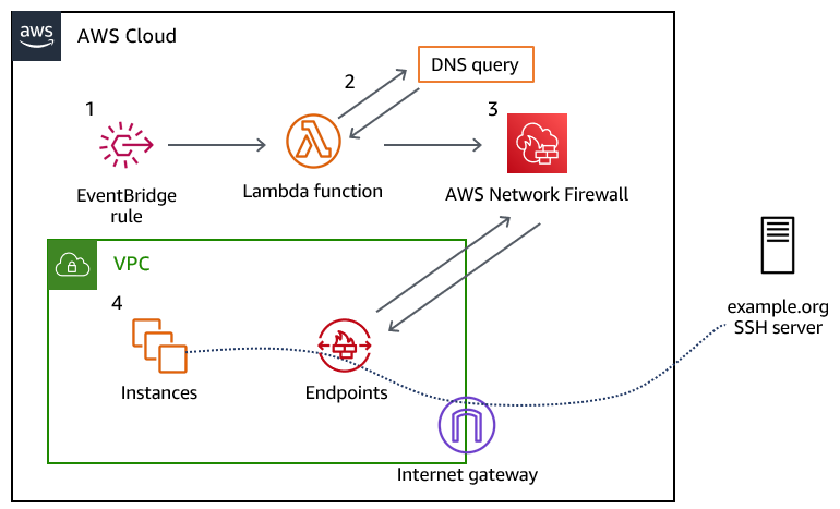
Figure 1 provides an overview of the solution and the resulting traffic flow.
Figure 1: Overview of the solution and the resulting traffic flow
The solution workflow is as follows:
An Amazon EventBridge rule invokes the Lambda function every 10 minutes. You can modify this frequency to meet your needs. You should consider the time-to-live (TTL) record of the DNS record that you are configuring when choosing this interval.
The Lambda function performs the DNS lookup for the provided domain, and updates a variable in an existing Network Firewall rule group. The rule group changes take a few seconds to fully apply to the nodes in your Network Firewall deployment.
The newly created Network Firewall rule group is associated with the Network Firewall policy to control traffic.
Traffic from the instances in your VPC flows through the Network Firewall endpoint, and if allowed, is routed through an internet gateway to the target server.
A DNS domain that you provide, which allows traffic for the protocol and port (or ports) that you plan to allow traffic to. This DNS domain needs to resolve to an IPv4 address or set of addresses; IPv6 is not supported, at this point.
Deploy the solution
We’ve provided a CloudFormation template to deploy this solution, which is located in the GitHub repository that accompanies this blog post.
Choose Stacks > Create Stack > With new resources (standard).
In the Specify template section, choose Upload a template file.
Choose Choose file, navigate to where you saved the CloudFormation template, and upload it. Then choose Next.
Specify a stack name for your CloudFormation stack.
In the Parameters section, for the Domain parameter, specify the name of the domain to which you will control access. The default value is set to example.org; however, note that the actual example.org doesn’t allow SSH traffic.
The remaining parameters have defaults to allow outbound SSH traffic to the specified domain. Adjust the LambdaJobFrequency variable so that it corresponds with the TTL of the DNS record that it will resolve. This allows the Lambda function to keep the IP address of the DNS record up to date, in the event that it changes. After you’ve configured the parameters, choose Next.
Figure 2: CloudFormation stack parameters
On the Configure stack options page, specify any further options needed or keep the default options, and then choose Next.
On the Review page, review the stack and parameters and select the check box to acknowledge that this template will create IAM resources. Choose Create Stack.
Check the stack creation status. Upon successful completion, the status shows CREATE_COMPLETE.
Figure 3: The successful creation of the CloudFormation stack
Test the solution
Before you test the newly created rule, make sure that the Lambda function has been invoked at least once from the EventBridge rule.
To verify the Lambda function results
In the AWS Management Console, navigate to the Lambda function Network-Firewall-Resolver-Function, and on the Monitor tab, choose View logs in CloudWatch.
Figure 4: Navigating to view logs in CloudWatch
Select the most recent log stream.
Verify that that a log line contains the entry StatefulRuleGroup updated successfully.
Figure 5: Examining the CloudWatch logs to verify that the Lambda function ran successfully
Associate the stateful rule group that was created by the stack, Lambda-Managed-Stateful-Rule with the existing Network Firewall policy that is attached to your VPC. To do this:
Navigate to VPC > Network Firewall > Firewall Policies and select your existing firewall policy.
In the Stateful rule groups section, for Actions, choose Add unmanaged stateful rule groups.
Select the check box for Lambda-Managed-Stateful-Rule, and then choose Add stateful rule group.
When the newly provisioned Lambda function runs successfully, it will resolve the IPv4 address for the domain (example.org) and associate the address with the stateful rule variable IP_NET. To validate that this has happened, do the following:
Choose the Lambda-Managed-Stateful-Rule rule group.
Navigate to the rule variable section, and choose IP_NET. If the Lambda function successfully resolved the provided domain name, the variable will contain the IPv4 addresses for the domain you provided, as shown in Figure 6.
Figure 6: Validating the rule variable details
Test the rule by attempting to connect to the domain that you specified in the CloudFormation template. Use an EC2 instance within the VPC that the network firewall rule is associated with, and attempt to establish an SSH connection to the domain that you specified. As shown by the SSH key negotiation in Figure 7, traffic is allowed through the network firewall, as intended.
Figure 7: SSH connectivity to the domain was successful
You can also configure the rule to drop the SSH connection, rather than permit it. To do this:
Choose the Lambda-Managed-Stateful-Rule rule group. In the Rules section, choose Edit Rules.
Modify the rule to take the Drop action, and save the rule group.
As shown by the lack of response from the host in Figure 8, the SSH connection cannot be established anymore.
Figure 8: An SSH connection cannot be established, due to the connection timing out
Cleanup
Follow the steps in this section to remove the resources created by this solution.
To remove the resources
Sign in to your AWS account where you deployed the CloudFormation stack and navigate to the Network Firewall console.
In the Stateful rule groups section, select the check box for Lambda-Managed-Stateful-Rule. For Actions, choose Disassociate from policy.
Figure 9: Disassociating the stateful rule from the existing policy
Navigate to the CloudFormation console, select the stack that you created, and then choose Delete. Upon successful deletion, the resources created by the stack will be deleted.
Conclusion
In this post, we’ve demonstrated how security and network administrators have the ability to permit or restrict non-HTTP and non-HTTPS traffic to a given domain by using Network Firewall. With this solution, administrators can enforce granular port- and protocol-level control to third-party domains. To learn more about rule group configuration in AWS Network Firewall, see Managing your own rule groups in the Developer Guide.
If you have feedback about this post, submit comments in the Comments section below. If you have questions about this post, contact AWS Support. You can also start a new thread on AWS Network Firewall re:Post to get answers from the community.
Want more AWS Security news? Follow us on Twitter.
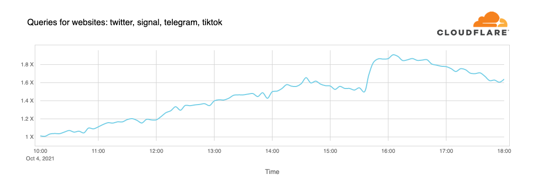
The Internet is a living organism. Technology changes, shifts in human behavior, social events, intentional disruptions, and other occurrences change the Internet in unpredictable ways, even to the trained eye.
Cloudflare Radar has long been the place to visit for accessing data and getting unique insights into how people and organizations are using the Internet across the globe, as well as those unpredictable changes to the Internet.
One of the most popular features on Radar has always been the “Most Popular Domains,” with both global and country-level perspectives. Domain usage signals provide a proxy for user behavior over time and are a good representation of what people are doing on the Internet.
Today, we’re going one step further and launching a new dataset called Radar Domain Rankings (Beta). Domain Rankings is based on aggregated 1.1.1.1 resolver data that is anonymized in accordance with our privacy commitments. The dataset aims to identify the top most popular domains based on how people use the Internet globally, without tracking individuals’ Internet use.
There are a few reasons why we’re doing this now. One is obviously to improve our Radar features with better data and incorporate new learnings. But also, ranking lists are used all over the Internet in all sorts of systems. One of the most used and trusted sources of domain rankings was Alexa, but that service was recently deprecated. We believe we are in a good position to provide a strong alternative.
Let’s see how we built it.
Differences in domain names
Before we dig into the data science behind Domain Rankings, it’s important to understand what a domain and DNS are. Internet domain names are human-readable dot-separated letters, digits and hyphens that correspond to a network resource, like a server or a website. However, your computer and applications don’t know what to do with a domain name; they need IP addresses to send and receive information over the network. DNS is the system that converts, or resolves, a domain name into an IP address. Think of it as an Internet phonebook for domain names.
Note: This is a simplification. A new standard called Internationalized Domain Names, or IDN, allows using Unicode strings in domain names.
Each dot defines a new hierarchy level, reading right to left. Domains can have multiple levels of depth. The highest level corresponds to country code top-level domains (ccTLDs) like .uk, .fr or .pt, or generic top-level domains (gTLDs) like .com, .org, or .net. These are normally assigned to and managed by either country-level entities or administrative organizations operating a registry.
Then there are the second-level domains like cloudflare.com or google.com. These are normally purchased and registered by individuals or organizations, which are then free to create and manage as many hostnames and hierarchy levels as they want.
Unfortunately, however, there are exceptions. For instance, many countries use second-level domain registration. One such example is the United Kingdom, where commercial domains can only be registered under the .co.uk hierarchy. That’s why Google in the UK isn’t google.uk, but rather google.co.uk.
But that’s not all. Some countries use 3rd level domain registrations. One example is Japan, which offers Regional Domain registration under cities like *.aisai.aichi.jp.
Projects like the Public Suffix List are a good starting point for understanding the variations involved, and how they affect validations and assumptions in other systems, such as cookies in web browsers.
Domain Rankings takes some of this nuance into account to inform the definition of our current ruleset:
We boil everything down to second-level domains, such as cloudflare.com or google.com.
However, if the second level is .edu, .com, .org, .gov, .net, .gov, .net, .co or .mil, then we use third-level domains.
We don’t distinguish between what we think is a website or an infrastructure system. A domain represents an Internet-available resource.
We will also semi-automate, curate and maintain a list of domains that map to popular platforms and services in the future. Example: fb.audio, fb.com, fb.watch, all map to a “facebook” platform.
Defining popularity
Definitions are important. We established what we consider a domain, but what does domain popularity mean exactly? Our research showed that the volume of traffic generated to a given domain doesn’t really work as a proxy for what we perceive as popular. Instead, Domain Rankings looks at the size of the population of users that look up a domain per unit of time. The more people who are interested in a domain, the more popular it is.
Sounds pretty straightforward, right? Well, it’s not. Our databases don’t have cookies, IPs, or other tracking artifacts, and we strip information that leads to identifying an individual from all of our data, by design.
The good news, however, is that we do a very good job at identifying automated traffic (for instance, you can read about Bot Management and how we use Machine Learning to detect bots in HTTP traffic in our blog) and we found we could develop a reasonable proxy for the unique users metric without sacrificing privacy (using other data points that we store for a limited period of time, like the ASN and high-level geolocation information of the request or the Cloudflare data center that served it).
Domain Rankings’ popularity metric is best described as the estimated relative size of the user population that accesses a domain over some period of time.
Our approach
We announced 1.1.1.1, our privacy-first consumer DNS resolver in 2018, and over the years it’s grown to become one of the top DNS services in the world. 1.1.1.1 is also part of a Research Agreement with APNIC in which we collaborate with them doing public research and DNS data insights.
The data we collect from it honors our privacy commitments, and is aggregated and stripped of any information that could lead to identifying or tracking users. We conducted a privacy examination by a Big Four accounting firm to determine whether the 1.1.1.1 resolver was effectively configured to meet our privacy commitments. You can read more about it in this blog, and the full report is publicly available on our compliance page.
Even without this personally identifying information, the resulting collection is vast and representative of Internet activity.
The 1.1.1.1 service is used in many ways. Regular (human) Internet users use it as their DNS resolver, either because they explicitly configured it in their devices, or their ISP did, or because they use WARP, or their browser uses 1.1.1.1 under the hood. However, servers and cloud infrastructure, IoT devices, home routers, and bots also use 1.1.1.1 extensively, which creates a lot of challenges for us when trying to identify human traffic.
We’ve been using DNS data to calculate the top and trending domains found on both the global and country pages on Cloudflare Radar. It’s been quite a learning experience trying to improve these lists. We have implemented aggregations, counts, filters, handling exceptions, and tried reducing noise, and yet they’re far from perfect. We felt that there had to be a better way.
We’ve spent the last six months building a variety of machine learning models to help us predict the rank of a domain.
Building the model was no easy feat. We experimented with multiple regression types first, to know exactly what the model was doing, and then more complex algorithms to get better performance. We played with different datasets, changed the population groups, variables (features), and combinations of variables, and used synthetic data.
After evaluation, one of our first conclusions was that building a model that could produce good results for the highest ranked domains and the long tail would be difficult.
The paper “A Long Way to the Top: Significance, Structure, and Stability of Internet Top Lists” describes this problem well. “The ranking of domains in the long tail should be based on significantly smaller and hence less reliable numbers.” Talking to our Research Team who submitted the collaboration paper “Toppling Top Lists: Evaluating the Accuracy of Popular Website Lists” to IMC 2022, got us to the same conclusion: the most popular domains (like google.com and facebook.com) have feature values disproportionally higher than the lower-ranked domains.
Therefore, we selected the two models that performed best. One model was trained on the population with the highest feature values, uses more features, and is used to generate the ordered top 100 domain list. A second model was trained on a more general group of domains, uses fewer features, and is used to get the top one million most popular domains, which we then divide into ranking buckets.
These buckets are ranked, but each bucket’s contents are intentionally unordered. For example, the second bucket of 10,000 most popular domains includes the set of domains that rank from 10,001 to 20,000, but give no further indication of the individual ranking of domains in that bucket. Given the size of some of these buckets and the window of time we use to populate them, they will inherently be exposed to more instability, too. We feel this is a good compromise between the described natural uncertainties of our long tail model and providing a reasonable idea of how close to the top a domain is.
Results
It’s important to mention there is no global view that can establish the perfect rank, and there’s no easy mechanism to confirm if a ranking is, ultimately, good. Data-driven results are always subject to some bias and skewing, related to the context of the organizations and systems that collect them. Sometimes all that can be done is to be transparent about potential sources of bias. The geographical distribution of customers and users, product characteristics, platform features, and behavioral diversity play an essential role in the final result. We are presenting the Cloudflare view, what we see.
Having said this, Cloudflare sits in a privileged position and handles a significant amount of Internet traffic. We have plenty of signals we can extract from our aggregated data, and believe that makes it possible to generate high quality domain rankings.
Domain Rankings are available today. You can head up to the Domains page and check it out:
Ordered list of the top 100 most popular domains globally and per country, based on our first model. Last 24 hours, updated daily.
Unordered global most popular domains datasets divided into buckets of the following sizes: 200, 500, 1,000, 2,000, 5,000, 10,000, 20,000, 50,000, 100,000, 200,000, 500,000, 1,000,000. Last 7 days, updated weekly.
Next steps
We will keep improving Domain Rankings and monitoring the results. Anyone can access them on Cloudflare Radar, read the results, and download the CSV files.
Feel free to explore our Domain Rankings and share feedback with us.
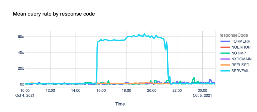
It can be frustrating to get errors (SERVFAIL response codes) returned from your DNS queries. It can be even more frustrating if you don’t get enough information to understand why the error is occurring or what to do next. That’s why back in 2020, we launched support for Extended DNS Error (EDE) Codes to 1.1.1.1.
As a quick refresher, EDE codes are a proposed IETF standard enabled by the Extension Mechanisms for DNS (EDNS) spec. The codes return extra information about DNS or DNSSEC issues without touching the RCODE so that debugging is easier.
Now we’re happy to announce we will return more error code types and include additional helpful information to further improve your debugging experience. Let’s run through some examples of how these error codes can help you better understand the issues you may face.
To try for yourself, you’ll need to run the dig or kdig command in the terminal. For dig, please ensure you have v9.11.20 or above. If you are on macOS 12.1, by default you only have dig 9.10.6. Install an updated version of BIND to fix that.
Let’s start with the output of an example dig command without EDE support.
In the output above, we tried to do DNSSEC validation on dnssec-failed.org. It returns a SERVFAIL, but we don’t have context as to why.
Now let’s try that again with 1.1.1.1’s EDE support.
% dig @1.1.1.1 dnssec-failed.org +dnssec

; <<>> DiG 9.18.0 <<>> @1.1.1.1 dnssec-failed.org +dnssec
; (1 server found)
;; global options: +cmd
;; Got answer:
;; ->>HEADER<<- opcode: QUERY, status: SERVFAIL, id: 34492
;; flags: qr rd ra; QUERY: 1, ANSWER: 0, AUTHORITY: 0, ADDITIONAL: 1

;; OPT PSEUDOSECTION:
; EDNS: version: 0, flags: do; udp: 1232
; EDE: 9 (DNSKEY Missing): (no SEP matching the DS found for dnssec-failed.org.)
;; QUESTION SECTION:
;dnssec-failed.org.		IN	A

;; Query time: 15 msec
;; SERVER: 1.1.1.1#53(1.1.1.1) (UDP)
;; WHEN: Fri Mar 04 12:53:45 PST 2022
;; MSG SIZE  rcvd: 103
We can see there is still a SERVFAIL. However, this time there is also an EDE Code 9 which stands for “DNSKey Missing”. Accompanying that, we also have additional information saying “no SEP matching the DS found” for dnssec-failed.org. That’s better!
Another nifty feature is that we will return multiple errors when appropriate, so you can debug each one separately. In the example below, we returned a SERVFAIL with three different error codes: “Unsupported DNSKEY Algorithm”, “No Reachable Authority”, and “Network Error”.
Here’s a list of the additional codes we now support:
Error Code Number
Error Code Name
1
Unsupported DNSKEY Algorithm
2
Unsupported DS Digest Type
5
DNSSEC Indeterminate
7
Signature Expired
8
Signature Not Yet Valid
9
DNSKEY Missing
10
RRSIGs Missing
11
No Zone Key Bit Set
12
NSEC Missing
We have documented all the error codes we currently support with additional information you may find helpful. Refer to our dev docs for more information.
Since my previous blog about Secondary DNS, Cloudflare’s DNS traffic has more than doubled from 15.8 trillion DNS queries per month to 38.7 trillion. Our network now spans over 270 cities in over 100 countries, interconnecting with more than 10,000 networks globally. According to w3 stats, “Cloudflare is used as a DNS server provider by 15.3% of all the websites.” This means we have an enormous responsibility to serve DNS in the fastest and most reliable way possible.
Although the response time we have on DNS queries is the most important performance metric, there is another metric that sometimes goes unnoticed. DNS Record Propagation time is how long it takes changes submitted to our API to be reflected in our DNS query responses. Every millisecond counts here as it allows customers to quickly change configuration, making their systems much more agile. Although our DNS propagation pipeline was already known to be very fast, we had identified several improvements that, if implemented, would massively improve performance. In this blog post I’ll explain how we managed to drastically improve our DNS record propagation speed, and the impact it has on our customers.
How DNS records are propagated
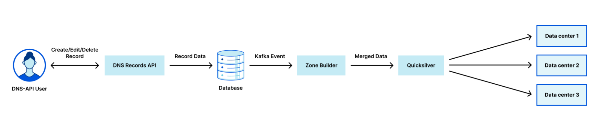
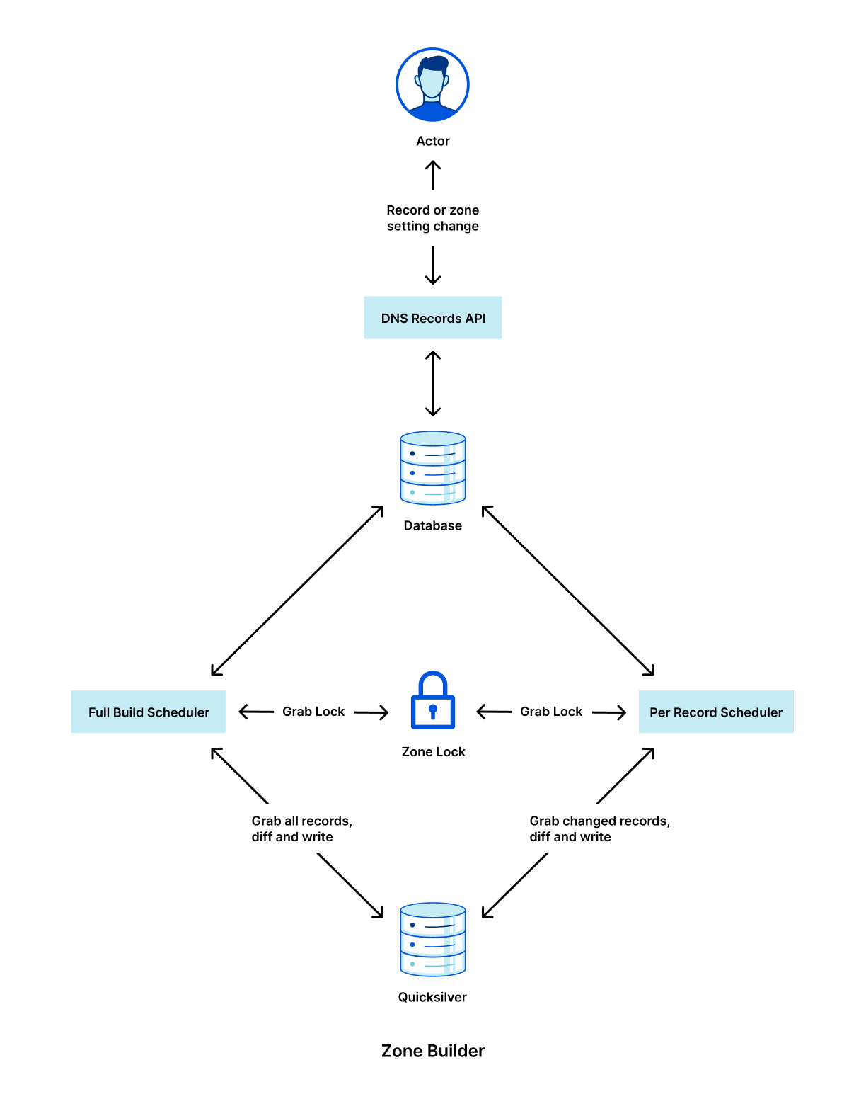
Cloudflare uses a multi-stage pipeline that takes our customers’ DNS record changes and pushes them to our global network, so they are available all over the world.
The steps shown in the diagram above are:
Customer makes a change to a record via our DNS Records API (or UI).
The change is persisted to the database.
The database event triggers a Kafka message which is consumed by the Zone Builder.
The Zone Builder takes the message, collects the contents of the zone from the database and pushes it to Quicksilver, our distributed KV store.
Quicksilver then propagates this information to the network.
Of course, this is a simplified version of what is happening. In reality, our API receives thousands of requests per second. All POST/PUT/PATCH/DELETE requests ultimately result in a DNS record change. Each of these changes needs to be actioned so that the information we show through our API and in the Cloudflare dashboard is eventually consistent with the information we use to respond to DNS queries.
Historically, one of the largest bottlenecks in the DNS propagation pipeline was the Zone Builder, shown in step 4 above. Responsible for collecting and organizing records to be written to our global network, our Zone Builder often ate up most of the propagation time, especially for larger zones. As we continue to scale, it is important for us to remove any bottlenecks that may exist in our systems, and this was clearly identified as one such bottleneck.
Growing pains
When the pipeline shown above was first announced, the Zone Builder received somewhere between 5 and 10 DNS record changes per second. Although the Zone Builder at the time was a massive improvement on the previous system, it was not going to last long given the growth that Cloudflare was and still is experiencing. Fast-forward to today, we receive on average 250 DNS record changes per second, a staggering 25x growth from when the Zone Builder was first announced.
The way that the Zone Builder was initially designed was quite simple. When a zone changed, the Zone Builder would grab all the records from the database for that zone and compare them with the records stored in Quicksilver. Any differences were fixed to maintain consistency between the database and Quicksilver.
This is known as a full build. Full builds work great because each DNS record change corresponds to one zone change event. This means that multiple events can be batched and subsequently dropped if needed. For example, if a user makes 10 changes to their zone, this will result in 10 events. Since the Zone Builder grabs all the records for the zone anyway, there is no need to build the zone 10 times. We just need to build it once after the final change has been submitted.
What happens if the zone contains one million records or 10 million records? This is a very real problem, because not only is Cloudflare scaling, but our customers are scaling with us. Today our largest zone currently has millions of records. Although our database is optimized for performance, even one full build containing one million records took up to 35 seconds, largely caused by database query latency. In addition, when the Zone Builder compares the zone contents with the records stored in Quicksilver, we need to fetch all the records from Quicksilver for the zone, adding time. However, the impact doesn’t just stop at the single customer. This also eats up more resources from other services reading from the database and slows down the rate at which our Zone Builder can build other zones.
Per-record build: a new build type
Many of you might already have the solution to this problem in your head:
Why doesn’t the Zone Builder just query the database for the record that has changed and propagate just the single record?
Of course this is the correct solution, and the one we eventually ended up at. However, the road to get there was not as simple as it might seem.
Firstly, our database uses a series of functions that, at zone touch time, create a PostgreSQL Queue (PGQ) event that ultimately gets turned into a Kafka event. Initially, we had no distinction for individual record events, which meant our Zone Builder had no idea what had actually changed until it queried the database.
Next, the Zone Builder is still responsible for DNS zone settings in addition to records. Some examples of DNS zone settings include custom nameserver control and DNSSEC control. As a result, our Zone Builder needed to be aware of specific build types to ensure that they don’t step on each other. Furthermore, per-record builds cannot be batched in the same way that zone builds can because each event needs to be actioned separately.
As a result, a brand new scheduling system needed to be written. Lastly, Quicksilver interaction needed to be re-written to account for the different types of schedulers. These issues can be broken down as follows:
Create a new Kafka event pipeline for record changes that contain information about the changed record.
Separate the Zone Builder into a new type of scheduler that implements some defined scheduler interface.
Implement the per-record scheduler to read events one by one in the correct order.
Implement the new Quicksilver interface for the per-record scheduler.
Below is a high level diagram of how the new Zone Builder looks internally with the new scheduler types.
It is critically important that we lock between these two schedulers because it would otherwise be possible for the full build scheduler to overwrite the per-record scheduler’s changes with stale data.
It is important to note that none of this per-record architecture would be possible without the use of Cloudflare’s black lie approach to negative answers with DNSSEC. Normally, in order to properly serve negative answers with DNSSEC, all the records within the zone must be canonically sorted. This is needed in order to maintain a list of references from the apex record through all the records in the zone. With this normal approach to negative answers, a single record that has been added to the zone requires collecting all records to determine its insertion point within this sorted list of names.
Bugs
I would love to be able to write a Cloudflare blog where everything went smoothly; however, that is never the case. Bugs happen, but we need to be ready to react to them and set ourselves up so that next time this specific bug cannot happen.
In this case, the major bug we discovered was related to the cleanup of old records in Quicksilver. With the full Zone Builder, we have the luxury of knowing exactly what records exist in both the database and in Quicksilver. This makes writing and cleaning up a fairly simple task.
When the per-record builds were introduced, record events such as creates, updates, and deletes all needed to be treated differently. Creates and deletes are fairly simple because you are either adding or removing a record from Quicksilver. Updates introduced an unforeseen issue due to the way that our PGQ was producing Kafka events. Record updates only contained the new record information, which meant that when the record name was changed, we had no way of knowing what to query for in Quicksilver in order to clean up the old record. This meant that any time a customer changed the name of a record in the DNS Records API, the old record would not be deleted. Ultimately, this was fixed by replacing those specific update events with both a creation and a deletion event so that the Zone Builder had the necessary information to clean up the stale records.
None of this is rocket surgery, but we spend engineering effort to continuously improve our software so that it grows with the scaling of Cloudflare. And it’s challenging to change such a fundamental low-level part of Cloudflare when millions of domains depend on us.
Results
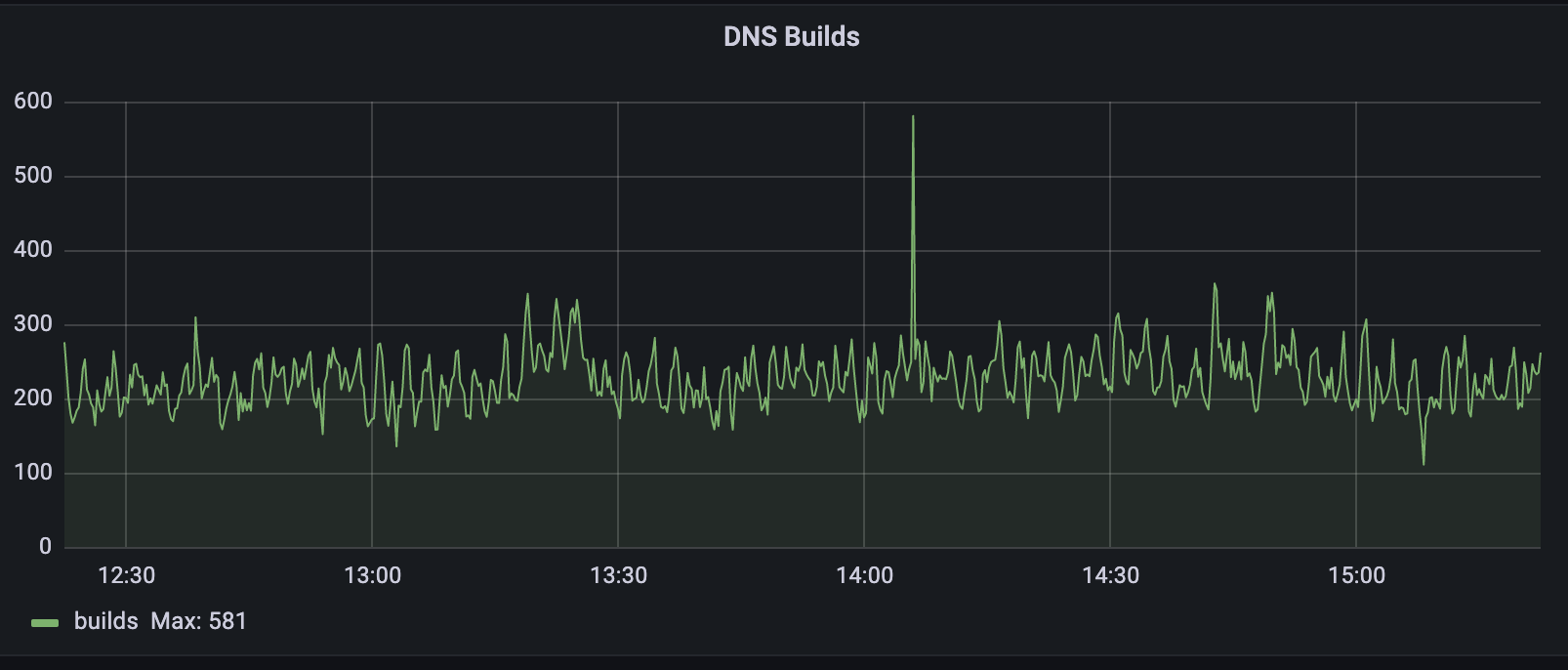
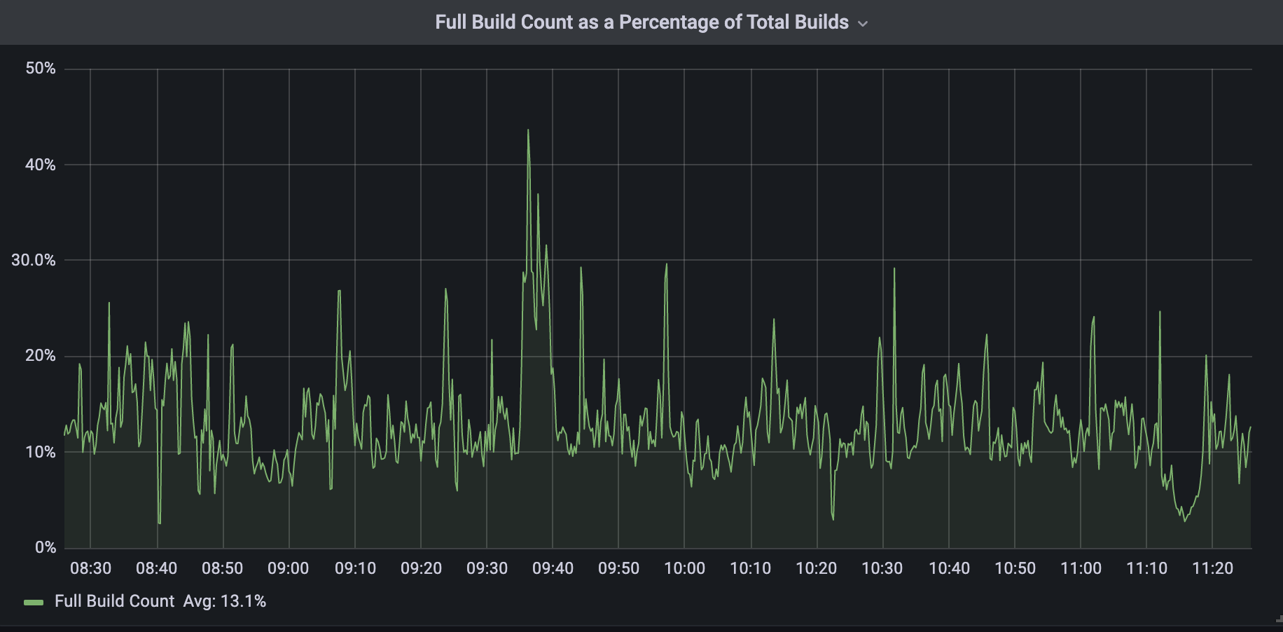
Today, all DNS Records API record changes are treated as per-record builds by the Zone Builder. As I previously mentioned, we have not been able to get rid of full builds entirely; however, they now represent about 13% of total DNS builds. This 13% corresponds to changes made to DNS settings that require knowledge of the entire zone’s contents.
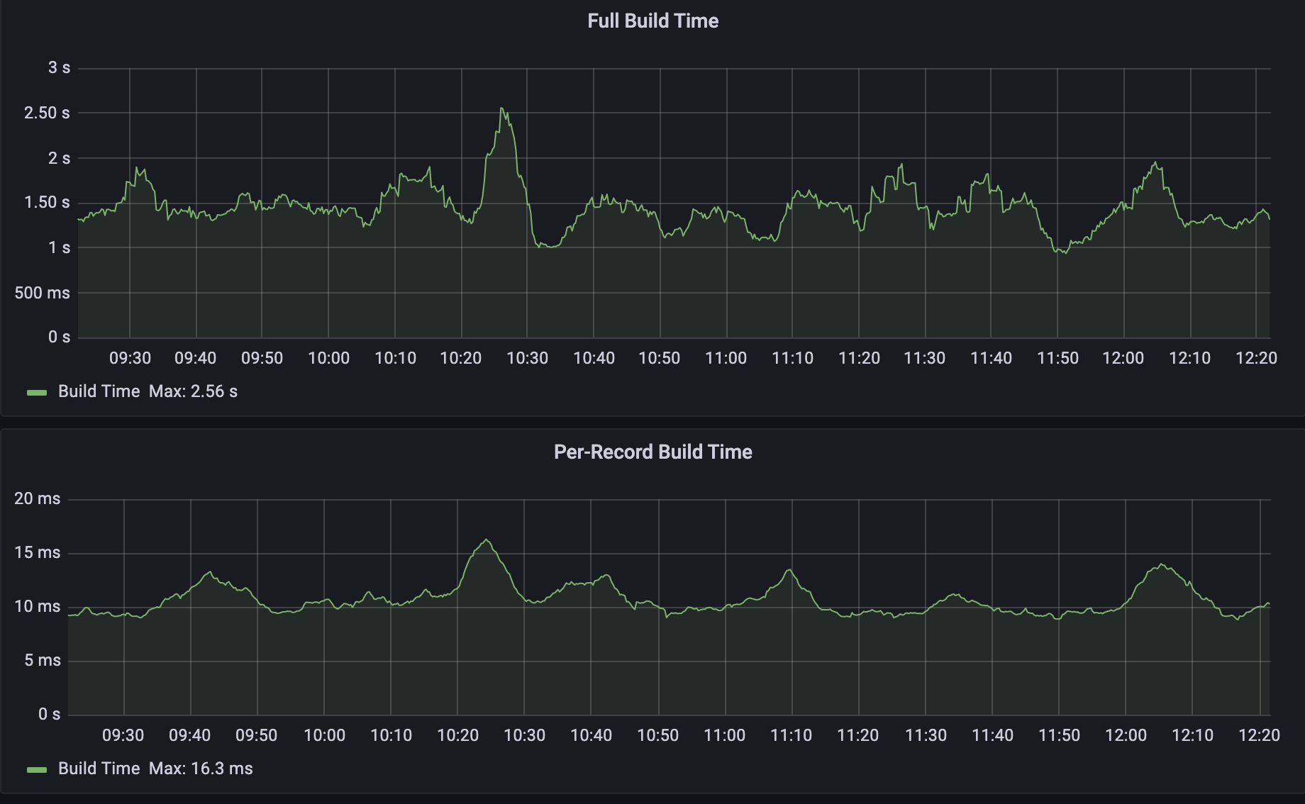
When we compare the two build types as shown below we can see that per-record builds are on average 150x faster than full builds. The build time below includes both database query time and Quicksilver write time.
From there, our records are propagated to our global network through Quicksilver.
The 150x improvement above is with respect to averages, but what about that 4000x that I mentioned at the start? As you can imagine, as the size of the zone increases, the difference between full build time and per-record build time also increases. I used a test zone of one million records and ran several per-record builds, followed by several full builds. The results are shown in the table below:
Build Type
Build Time (ms)
Per Record #1
6
Per Record #2
7
Per Record #3
6
Per Record #4
8
Per Record #5
6
Full #1
34032
Full #2
33953
Full #3
34271
Full #4
34121
Full #5
34093
We can see that, given five per-record builds, the build time was no more than 8ms. When running a full build however, the build time lasted on average 34 seconds. That is a build time reduction of 4250x!
Given the full build times for both average-sized zones and large zones, it is apparent that all Cloudflare customers are benefitting from this improved performance, and the benefits only improve as the size of the zone increases. In addition, our Zone Builder uses less database and Quicksilver resources meaning other Cloudflare systems are able to operate at increased capacity.
Next Steps
The results here have been very impactful, though we think that we can do even better. In the future, we plan to get rid of full builds altogether by replacing them with zone setting builds. Instead of fetching the zone settings in addition to all the records, the zone setting builder would just fetch the settings for the zone and propagate that to our global network via Quicksilver. Similar to the per-record builds, this is a difficult challenge due to the complexity of zone settings and the number of actors that touch it. Ultimately if this can be accomplished, we can officially retire the full builds and leave it as a reminder in our git history of the scale at which we have grown over the years.
In addition, we plan to introduce a batching system that will collect record changes into groups to minimize the number of queries we make to our database and Quicksilver.
Does solving these kinds of technical and operational challenges excite you? Cloudflare is always hiring for talented specialists and generalists within our Engineering and other teams.
Today, I have the pleasure to announce that we’re giving everyone the ability to proxy DNS wildcard records. Previously, this feature was only available to our Enterprise customers. After many of our free and pay-as-you-go users reached out, we decided that this feature should be available to everyone.
What is a wildcard DNS record?
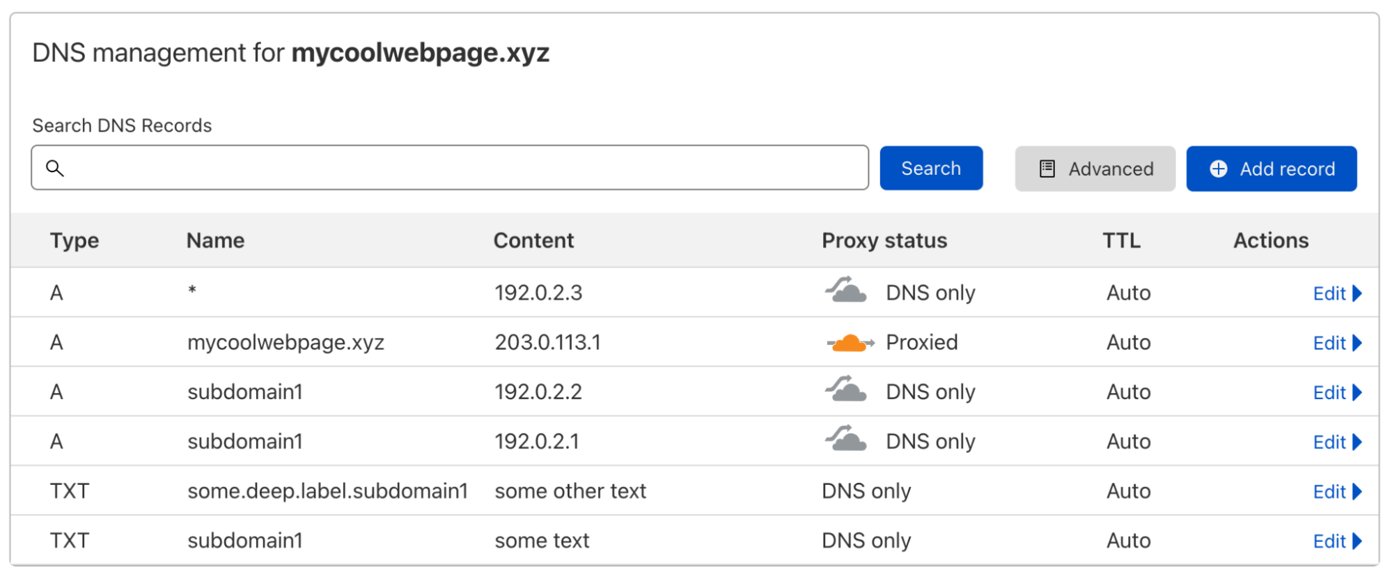
A DNS record usually maps a domain name to one or multiple IP addresses or another resource associated with that name, so it’s a one-to-many mapping. Let’s look at an example:
When I do a DNS lookup for the IP address of subdomain1.mycoolwebpage.xyz, I get two IP addresses back, because I have added two A records on that subdomain:
$ dig subdomain1.mycoolwebpage.xyz -t a +short
192.0.2.1
192.0.2.2
I could specify the target of all subdomains like this, with one or multiple DNS records per subdomain. But what if I have hundreds or even thousands of subdomains that I all want to point to the same resource?
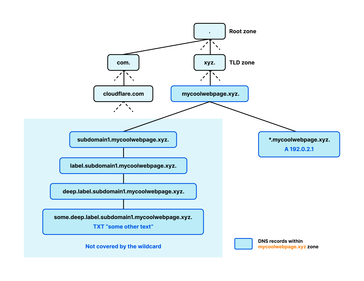
This is where a wildcard DNS record comes in. By using the asterisk symbol "*" in the Name field, I can create one or multiple DNS records that are used as the response for all subdomains that are not specifically covered by another DNS record (more on this later). So the wildcard record you can see in the screenshot above is covering *.mycoolwebpage.xyz, meaning all subdomains of mycoolwebpage.xyz. This can also be done on deeper levels, like on *.www.mycoolwebpage.xyz.
If I perform a lookup for subdomain2.mycoolwebpage.xyz, the target I specified in the wildcard record will be used as the response. Again, this is only happening because there is no DNS record specifically for this subdomain.
$ dig subdomain2.mycoolwebpage.xyz -t a +short
192.0.2.3
And it is often overlooked that a wildcard record does not only cover the level it is set on directly, but deeper levels, as well:
$ dig some.deep.label.subdomain2.mycoolwebpage.xyz -t a +short
192.0.2.3
Also, a wildcard DNS record does not cover the apex of the zone (in this example the apex is mycoolwebpage.xyz).
A few more things to know about wildcard records
Below you can find additional rules that apply to wildcard DNS records you should be aware of:
Wildcards are only supported on the first label. Meaning something like subdomain.*.mycoolwebpage.xyz is not a wildcard on the level of the asterisk character. If you create a DNS record with that name, the asterisk is interpreted as the literal character and not as the wildcard operator.
You cannot create wildcards on multiple levels. So if you create a DNS record on *.*.mycoolwebpage.xyz, only the first asterisk is interpreted as a wildcard while the second one is interpreted as the literal “*” character.
Wildcards will be applied for multiple levels. But a specific record on any equal or lower level will terminate anything on or below this specific record — independent of the type of that specific record. Here is an example. If you have only these two records on your domain
subdomain1.mycoolwebpage.xyz  TXT  “some text”
*.mycoolwebpage.xyz  	A  192.0.2.3
the wildcard record will be used for queries going to any subdomain of mycoolwebpage.xyzexceptsubdomain1.mycoolwebpage.xyz or anything below that specific label, like deeper.label.subdomain1.mycoolwebpage.xyz — simply because there already exists a record on subdomain1.mycoolwebpage.xyz. However, the wildcard will be used for deeper labels that are not below the specific record on subdomain1 — for example, deeper.label.subdomain2.mycoolwebpage.xyz.
To expand on this rule: if you think of DNS as a tree starting from the root zone (see the diagram below), simply the existence of a branch terminates the wildcard for all records on that branch. In the example above the wildcard was terminated for anything on the label subdomain1 and below, but even if there only exists a record on a deeper level, anything above will also be terminating the wildcard. This example should make it clear. If you only have the following two records on your domain, as shown in the diagram below
some.deep.label.subdomain1.mycoolwebpage.xyz  TXT  “some other text”
*.mycoolwebpage.xyz  	A  192.0.2.3
a query to label.subdomain1.mycoolwebpage.xyz for an A record is not covered by the wildcard because it is a node on the existing branch ending in the TXT record above.
Wildcard records only cover the record type they are specified for. If you add a wildcard A record for *.mycoolwebpage.xyz it will not cover queries specifying AAAA records (or any other type). But as mentioned in the previous point, a record on a specific label will terminate the wildcard for this label and everything below even if it’s a different record type.
All the above and more can be found in RFC4592. Not the type to read through complex RFCs but still generally interested in how DNS works, go check out Julia Evans’ wizard zines about DNS, she did a great job explaining all the complexities about DNS in an easy to digest way.
What is a proxied wildcard DNS record?
Cloudflare provides a range of features (including Caching, Firewall, or Workers) that require you to proxy the specific hostname you want to use these features on. You can proxy DNS records of the type A, AAAA, and CNAME. These record types are used to specify the origin server of a hostname which expects traffic via HTTP/S.
Proxying a wildcard DNS record works exactly as proxying a specific record. In the Cloudflare dashboard, navigate to the DNS app and either create a new wildcard record or edit an existing record and toggle the proxy status to Proxied. Previously, we only allowed this on wildcard records if the domain was upgraded to the Enterprise plan, but this feature is now available on all plan levels!
Once you have enabled the proxy status of your wildcard DNS record, Cloudflare nameservers will respond with two Cloudflare anycast IPs instead of the origin IP(s) you have specified for that record. These Cloudflare IPs are advertised on our global network from more than 275 locations in more than 100 countries.
$ dig subdomain2.mycoolwebpage.xyz -t a +short
104.18.35.126
172.64.152.130
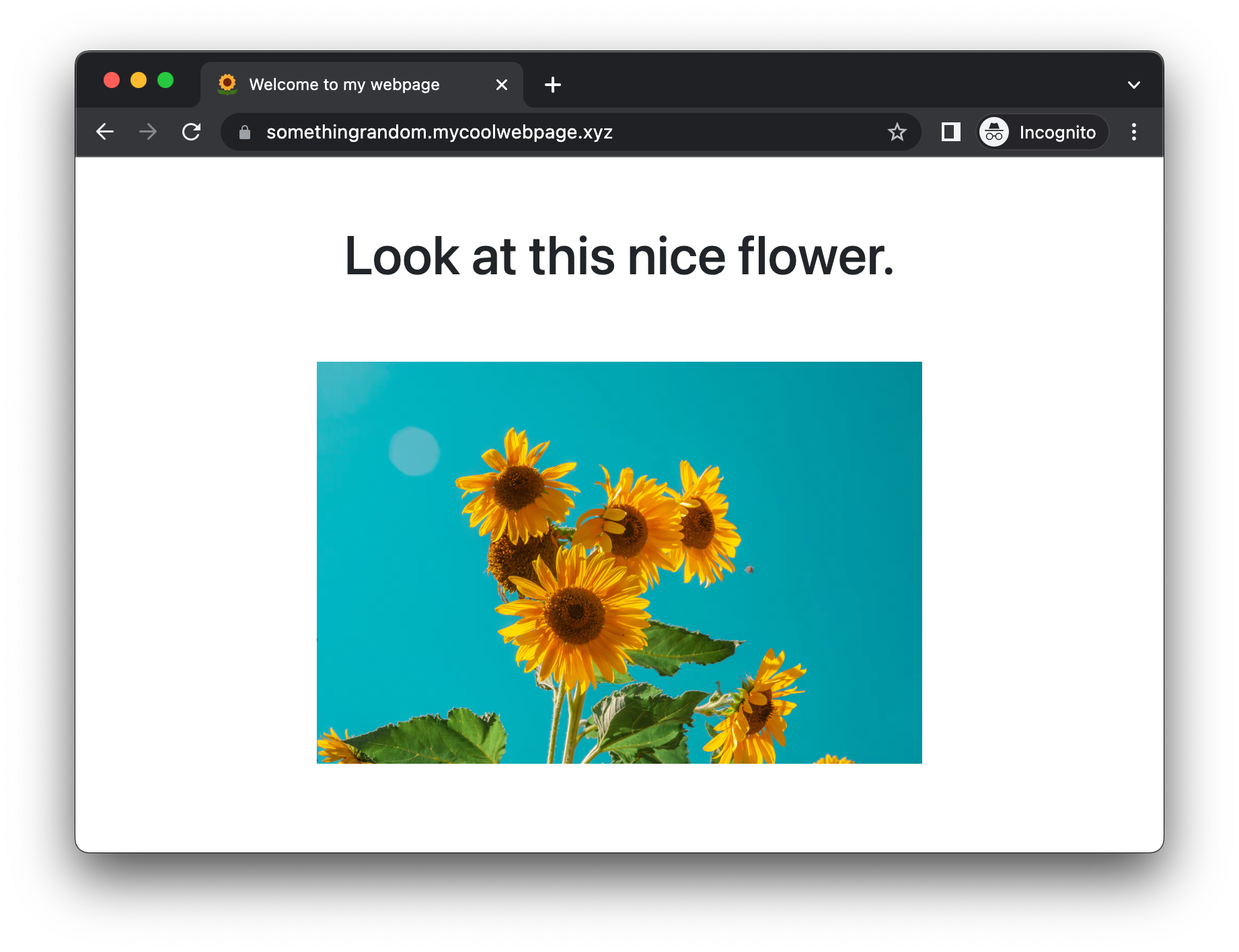
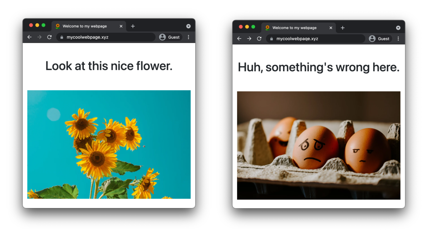
In the example above, this will ensure that all HTTP/S requests sent to subdomain2.mycoolwebpage.xyz or any other subdomain that is covered by the proxied wildcard DNS record are proxied by Cloudflare’s network, specifically the closest Cloudflare data center. Go see for yourself and pick a random subdomain of mycoolwebpage.xyz. You will see a simple page that is generated using Cloudflare Workers:
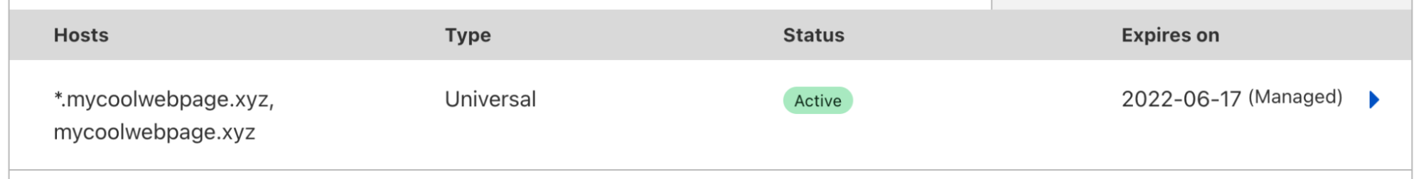
And the cool thing is that you don’t even have to think about creating a TLS certificate. By default, Cloudflare will issue and automatically renew a certificate for your zone apex (mycoolwebpage.xyz) and all subdomains on the next level (*.mycoolwebpage.xyz).
If you want to proxy a wildcard DNS record on a deeper level like *.www.mycoolwebpage.xyz you can subscribe to Cloudflare Advanced Certificate Manager and get a certificate that is covering that wildcard like this:
Try it yourself on your domain
If you are not already using Cloudflare DNS for your domain, it is very easy to move from your existing DNS provider and can be done in a few minutes. Head over to our developer documentation for detailed instructions on how to change your authoritative nameservers.
1.1.1.1 sees approximately 600 billion queries per day. However, proportionally, most queries sent to this resolver are over cleartext: 89% over UDP and TCP combined, and the remaining 11% are encrypted. We care about end-user privacy and would prefer to see all of these queries sent to us over an encrypted transport using DNS-over-TLS or DNS-over-HTTPS. Having a mechanism by which clients could discover support for encrypted protocols such as DoH or DoT will help drive this number up and lead to more name encryption on the Internet. That’s where DDR – or Discovery of Designated Resolvers – comes into play. As of today, 1.1.1.1 supports the latest version of DDR so clients can automatically upgrade non-secure UDP and TCP connections to secure connections. In this post, we’ll describe the motivations for DDR, how the mechanism works, and, importantly, how you can test it out as a client.
DNS transports and public resolvers
We initially launched our public recursive resolver service 1.1.1.1 over three years ago, and have since seen its usage steadily grow. Today, it is one of the fastest public recursive resolvers available to end-users, supporting the latest security and privacy DNS transports such as HTTP/3 for DNS-over-HTTPS (DoH), as well as Oblivious DoH.
As a public resolver, all clients, regardless of type, are typically manually configured based on a user’s desired performance, security, and privacy requirements. This choice reflects answers to two separate but related types of questions:
What recursive resolver should be used to answer my DNS queries? Does the resolver perform well? Does the recursive resolver respect my privacy?
What protocol should be used to speak to this particular recursive resolver? How can I keep my DNS data safe from eavesdroppers that should otherwise not have access to it?
The second question primarily concerns technical matters. In particular, whether or not a recursive resolver supports DoH is simple enough to answer. Either the recursive resolver does or does not support it!
In contrast, the first question is primarily a matter of policy. For example, consider the question of choosing between a local network-provided DNS recursive resolver and a public recursive resolver. How do resolver features (including DoH support, for example) influence this decision? How does the resolver’s privacy policy regarding data use and retention influence this decision? More generally, what information about recursive resolver capabilities is available to clients in making this decision and how is this information delivered to clients?
These policy questions have been the topic of substantial debate in the Internet Engineering Task Force (IETF), the standards body where DoH was standardized, and is the one facet of the Adaptive DNS Discovery (ADD) Working Group, which is chartered to work on the following items (among others):
– Define a mechanism that allows clients to discover DNS resolvers that support encryption and that are available to the client either on the public Internet or on private or local networks.
– Define a mechanism that allows communication of DNS resolver information to clients for use in selection decisions. This could be part of the mechanism used for discovery, above.
In other words, the ADD Working Group aims to specify mechanisms by which clients can obtain the information they need to answer question (1). Critically, one of those pieces of information is what encrypted transport protocols the recursive resolver supports, which would answer question (2).
As the answer to question (2) is purely technical and not a matter of policy, the ADD Working Group was able to specify a workable solution that we’ve implemented and tested with existing clients. Before getting into the details of how it works, let’s dig into the problem statement here and see what’s required to address it.
Threat model and problem statement
The DDR problem is relatively straightforward: given the IP address of a DNS recursive resolver, how can one discover parameters necessary for speaking to the same resolver using an encrypted transport? (As above, discovering parameters for a different resolver is a distinctly different problem that pertains to policy and is therefore out of scope.)
This question is only meaningful insofar as using encryption helps protect against some attacker. Otherwise, if the network was trusted, encryption would add no value! A direct consequence is that this question assumes the network – for some definition of “the network” – is untrusted and encryption helps protect against this network.
But what exactly is the network here? In practice, the topology typically looks like the following:
Typical DNS configuration from DHCP
Again, for DNS discovery to have any meaning, we assume that either the ISP or home network – or both – is untrusted and malicious. The setting here depends on the client and the network they are attached to, but it’s generally simplest to assume the ISP network is untrusted.
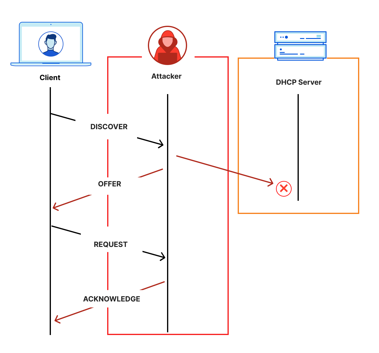
This question also makes one important assumption: clients know the desired recursive resolver address. Why is this important? Typically, the IP address of a DNS recursive resolver is provided via Dynamic Host Configuration Protocol (DHCP). When a client joins a network, it uses DHCP to learn information about the network, including the default DNS recursive resolver. However, DHCP is a famously unauthenticated protocol, which means that any active attacker on the network can spoof the information, as shown below.
Unauthenticated DHCP discovery
One obvious attacker vector would be for the attacker to redirect DNS traffic from the network’s desired recursive resolver to an attacker-controlled recursive resolver. This has important implications on the threat model for discovery.
First, there is currently no known mechanism for encrypted DNS discovery in the presence of an active attacker that can influence the client’s view of the recursive resolver’s address. In other words, to make any meaningful improvement, DNS discovery assumes the client’s view of the DNS recursive resolver address is correct (and obtained through some secure mechanism). A second implication is that the attacker can simply block any attempt of client discovery, preventing upgrade to encrypted transports. This seems true of any interactive discovery mechanism. As a result, DNS discovery must relax this attacker’s capabilities somewhat: rather than add, drop, or modify packets, the attacker can only add or modify packets.
Altogether, this threat model lets us sharpen the DNS discovery problem statement: given the IP address of a DNS recursive resolver, how can one securely discover parameters necessary for speaking to the same resolver using an encrypted transport in the presence of an active attacker that can add or modify packets? It should be infeasible, for example, for the attacker to redirect the client from the resolver that it knows at the outset to one the attacker controls.
So how does this work, exactly?
DDR mechanics
DDR depends on two mechanisms:
Certificate-based authentication of encrypted DNS resolvers.
SVCB records for encoding and communicating DNS parameters.
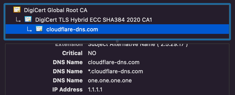
Certificates allow resolvers to prove authority for IP addresses. For example, if you view the certificate for one.one.one.one, you’ll see several IP addresses listed under the SubjectAlternativeName extension, including 1.1.1.1.
SubjectAltName list of the one.one.one.one certificate
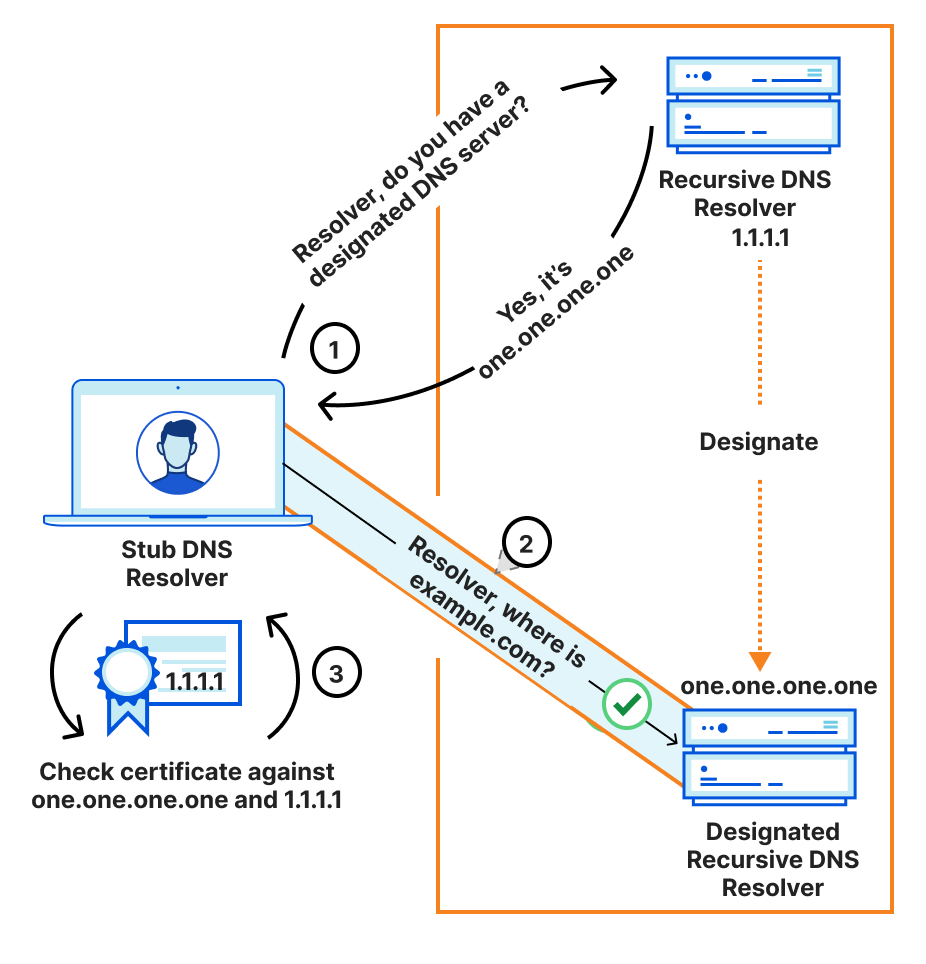
How does DDR combine these two to solve the discovery problem above? In three simple steps:
Clients query the expected DNS resolver for its designations and their parameters with a special-purpose SVCB record.
Clients open a secure connection to the designated resolver, for example, one.one.one.one, authenticating the resolver against the one.one.one.one name.
Clients check that the designated resolver is additionally authenticated for the IP address of the origin resolver. That is, the certificate for one.one.one.one, the designated resolver, must include the IP address 1.1.1.1, the original designator resolver.
If this validation completes, clients can then use the secure connection to the designated resolver. In pictures, this is as follows:
DDR discovery process
This demonstrates that the encrypted DNS resolver is authoritative for the client’s original DNS resolver. Or, in other words, that the original resolver and the encrypted resolver are effectively “the same.” An encrypted resolver that does not include the originally requested resolver IP address on its certificate would fail the validation, and clients are not expected to follow the designated upgrade path. This entire process is referred to as “Verified Discovery” in the DDR specification.
Experimental deployment and next steps
To enable more encrypted DNS on the Internet and help the standardization process, 1.1.1.1 now has experimental support for DDR. You can query it directly to find out:
$ dig +short @1.1.1.1 _dns.resolver.arpa type64

QUESTION SECTION
_dns.resolver.arpa.               IN SVCB

ANSWER SECTION
_dns.resolver.arpa.                           300    IN SVCB  1 one.one.one.one. alpn="h2,h3" port="443" ipv4hint="1.1.1.1,1.0.0.1" ipv6hint="2606:4700:4700::1111,2606:4700:4700::1001" key7="/dns-query{?name}"
_dns.resolver.arpa.                           300    IN SVCB  2 one.one.one.one. alpn="dot" port="853" ipv4hint="1.1.1.1,1.0.0.1" ipv6hint="2606:4700:4700::1111,2606:4700:4700::1001"

ADDITIONAL SECTION
one.one.one.one.                              300    IN AAAA  2606:4700:4700::1111
one.one.one.one.                              300    IN AAAA  2606:4700:4700::1001
one.one.one.one.                              300    IN A     1.1.1.1
one.one.one.one.                              300    IN A     1.0.0.1
This command sends a SVCB query (type64) for the reserved name _dns.resolver.arpa to 1.1.1.1. The output lists the contents of this record, including the DoH and DoT designation parameters. Let’s walk through the contents of this record:
This says that the DoH target one.one.one.one is accessible over port 443 (port=”443”) using either HTTP/2 or HTTP/3 (alpn=”h2,h3”), and the DoH path (key7) for queries is “/dns-query{?name}”.
Moving forward
DDR is a simple mechanism that lets clients automatically upgrade to encrypted transport protocols for DNS queries without any manual configuration. At the end of the day, users running compatible clients will enjoy a more private Internet experience. Happily, both Microsoft and Apple recently announced experimental support for this emerging standard, and we’re pleased to help them and other clients test support. Going forward, we hope to help add support for DDR to open source DNS resolver software such as dnscrypt-proxy and Bind. If you’re interested in helping us continue to drive adoption of encrypted DNS and related protocols to help build a better Internet, we’re hiring!
Today, we’re announcing Foundation DNS, Cloudflare’s new premium DNS offering that provides unparalleled reliability, supreme performance and is able to meet the most complex requirements of infrastructure teams.
Let’s talk money first
When you’re signing an enterprise DNS deal, usually DNS providers request three inputs from you in order to generate a quote:
Number of zones
Total DNS queries per month
Total DNS records across all zones
Some are considerably more complicated and many have pricing calculators or opaque “Contact Us” pricing. Planning a budget around how you may grow brings unnecessary complexity, and we think we can do better. Why not make this even simpler? Here you go: We decided to charge Foundation DNS based on a single input for our enterprise customers: Total DNS queries per month.This way, we expect to save companies money and even more importantly, remove complexity from their DNS bill.
And don’t worry, just like the rest of our products, DDoS mitigation is still unmetered. There won’t be any hidden overage fees in case your nameservers are DDoS’d or the number of DNS queries exceeds your quota for a month or two.
Why is DNS so important?
The Domain Name System (DNS) is nearly as old as the Internet itself. It was originally defined in RFC882 and RFC883 in 1983 out of the need to create a mapping between hostnames and IP addresses. Back then, the authors wisely stated: “[The Internet] is a large system and is likely to grow much larger.” [RFC882]. Today there are almost 160 Million domain names just under the .com, one of the largest Top Level Domains (TLD) [source].
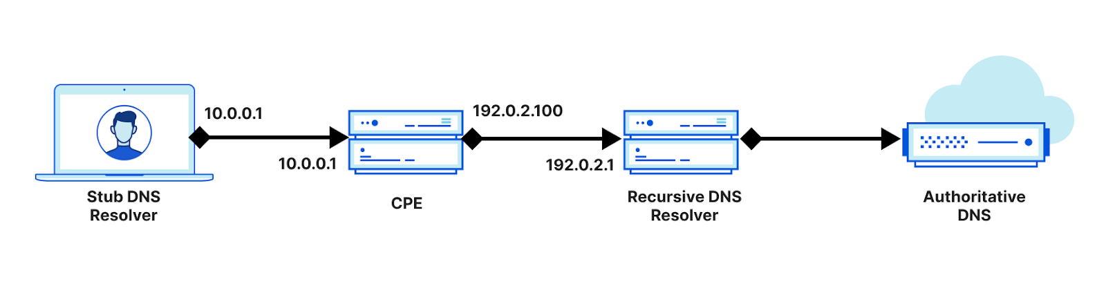
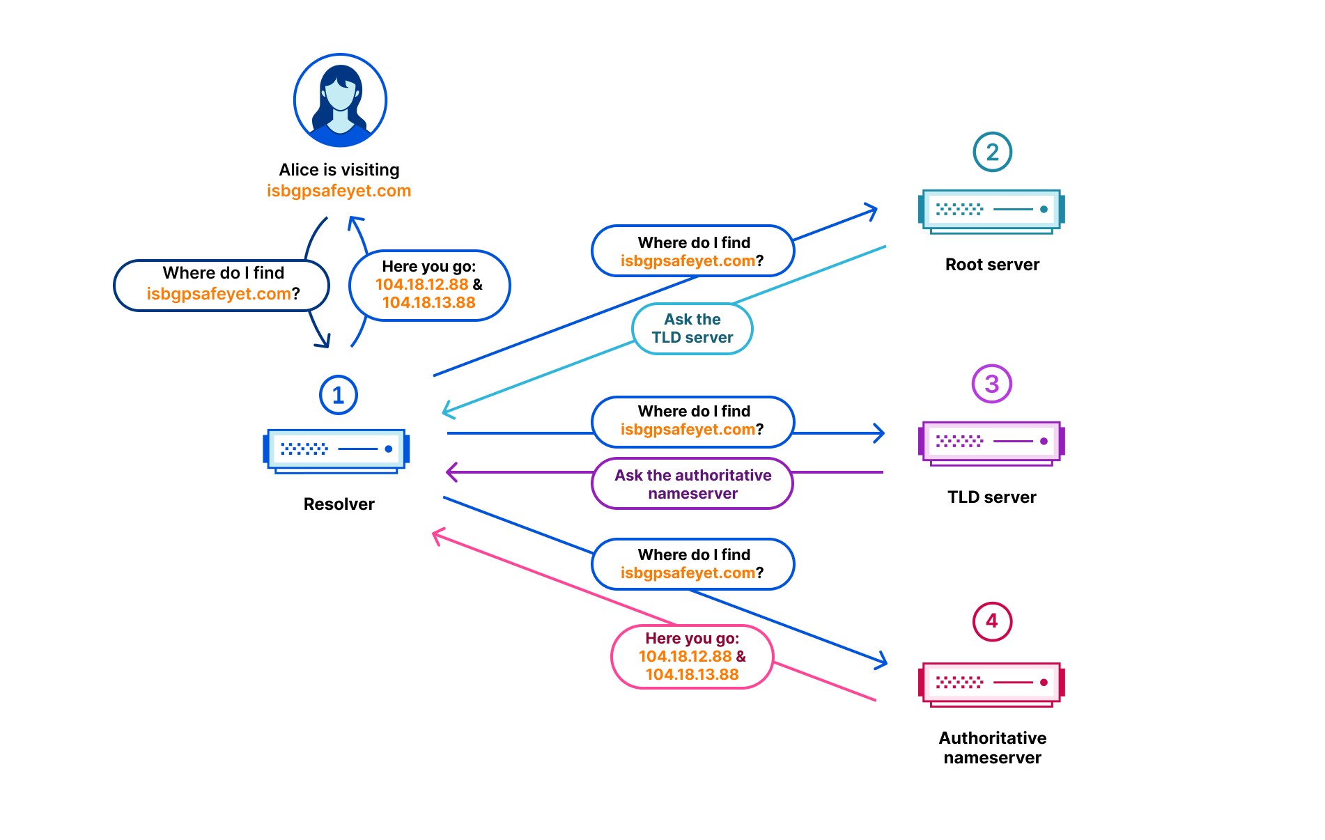
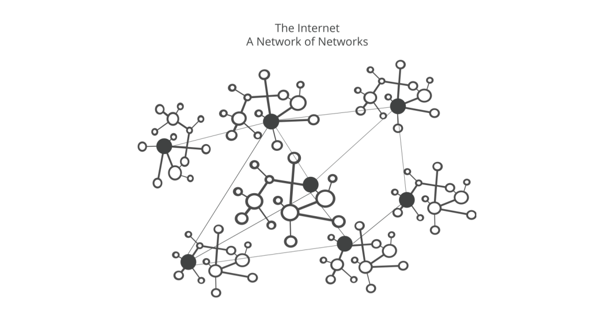
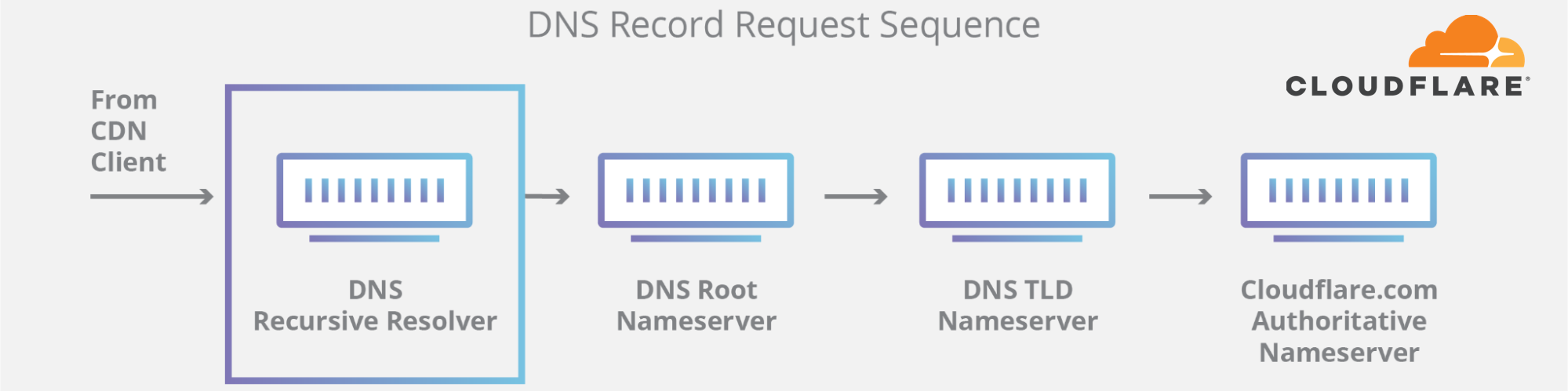
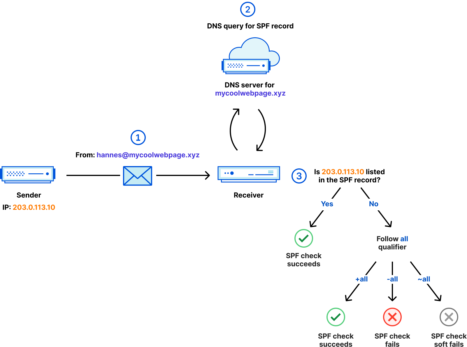
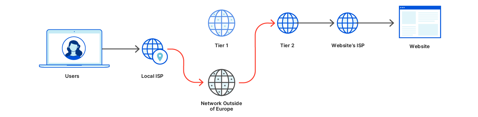
By design, DNS is a hierarchical and highly distributed system, but as an end user you usually only communicate with a resolver (1) that is either assigned or operated by your Internet Service Provider (ISP) or directly configured by your employer or yourself. The resolver communicates with one of the root servers (2), the responsible TLD server (3) and the authoritative nameserver (4) of the domain in question. In many cases all of these four parties are operated by a different entity and located in different regions, maybe even continents.
As we have seen in the recent past, if your DNS infrastructure goes down you are in serious trouble, and it likely will cost you a lot of money and potentially damage your reputation. So as a domain owner you want that DNS lookups to your domain are answered 100% of the time and ideally as quickly as possible. So what can you do? You cannot influence which resolver your users have configured. You cannot influence the root server. You can choose which TLD server is involved by picking a domain name with the respective TLD. But if you are bound to a certain TLD for other reasons then that is out of your control as well. What you can easily influence is the provider for your authoritative nameservers. So let’s take a closer look at Cloudflare’s authoritative DNS offering.
A look at Cloudflare’s Authoritative DNS
Authoritative DNS is one of our oldest products, and we have spent a lot of time making it great. All DNS queries are answered from our global anycast network with a presence in more than 250 cities. This way we can deliver supreme performance while always guaranteeing global availability. And of course, we leverage our extensive experience in mitigating DDoS attacks to prevent anyone from knocking down our nameservers and with that the domains of our customers.
DNS is critically important to Cloudflare because up until the release of Magic Transit, DNS was how every user on the Internet was directed to Cloudflare to protect and accelerate our customer’s applications. If our DNS answers were slow, Cloudflare was slow. If our DNS answers were unavailable, Cloudflare was unavailable. Speed and reliability of our authoritative DNS is paramount to the speed and reliability of Cloudflare, as it is to our customers. We have also had our customers push our DNS infrastructure as they’ve grown with Cloudflare. Today our largest customer zone has more than 3 million records and the top 5 are reaching almost 10 million records combined. Those customers rely on Cloudflare to push new DNS record updates to our edge in seconds, not minutes. Due to this importance and our customer’s needs, over the years we have grown our dedicated DNS engineering team focused on keeping our DNS stack fast and reliable.
The security of the DNS ecosystem is also important. Cloudflare has always been a proponent of DNSSEC. Signing and validating DNS answers through DNSSEC ensures that an on-path attacker cannot hijack answers and redirect traffic. Cloudflare has always offered DNSSEC for free on all plan levels, and it will continue to be a no charge option for Foundation DNS. For customers who also choose to use Cloudflare as a registrar, simple one-click deployment of DNSSEC is another key feature that ensures our customers’ domains are not hijacked, and their users are protected. We support RFC 8078 for one-click deployment on external registrars as well.
But there are other issues that can bring parts of the Internet to a halt and these are mostly out of our control: route leaks or even worse route hijacking. While DNSSEC can help with mitigating route hijacks, unfortunately not all recursive resolvers will validate DNSSEC. And even if the resolver does validate, a route leak or hijack to your nameservers will still result in downtime. If all your nameserver IPs are affected by such an event, your domain becomes unresolvable.
With many providers each of your nameservers usually resolves to only one IPv4 and one IPv6 address. If that IP address is not reachable — for example because of network congestion or, even worse, a route leak — the entire nameserver becomes unavailable leading to your domain becoming unresolvable. Even worse, some providers even use the same IP subnet for all their nameservers. So if there is an issue with that subnet all nameservers are down.
All nameserver IPs are part of 205.251.192.0/21. Thankfully, AWS is now signing their ranges through RPKI and this makes it less likely to leak… provided that the resolver ISP is validating RPKI. But if the resolver ISP does not validate RPKI and should this subnet be leaked or hijacked, resolvers wouldn’t be able to reach any of the nameservers and aws.com would become unresolvable.
It goes without saying that Cloudflare signs all of our routes and are pushing the rest of the Internet to minimize the impact of route leaks, but what else can we do to ensure that our DNS systems remain resilient through route leaks while we wait for RPKI to be ubiquitously deployed?
Today, when you’re using Cloudflare DNS on the Free, Pro, Business or Enterprise plan, your domain gets two nameservers of the structure <name>.ns.cloudflare.com where <name> is a random first name.
Now, as we learned before, in order for a domain to be available, its nameservers have to be available. This is why each of these nameservers resolves to 3 anycast IPv4 and 3 anycast IPv6 addresses.
The essential detail to notice here is that each of the 3 IPv4 and 3 IPv6 addresses is from a different /8 IPv4 (/45 for IPv6) block. So in order for your nameservers to become unavailable via IPv4, the route leak would have to affect exactly the corresponding subnets across all three /8 IPv4 blocks. This type of event, while theoretically is possible, is virtually impossible in practical terms.
How can this be further improved?
Customers using Foundation DNS will be assigned a new set of advanced nameservers hosted on foundationdns.com and foundationdns.net. These nameservers will be even more resilient than the default Cloudflare nameservers. We will be announcing more details about how we’re achieving this early next year, so stay tuned. All external Cloudflare domains (such as cloudflare.com) will transition to these nameservers in the new year.
There is even more
We’re glad to announce that we are launching two highly requested features:
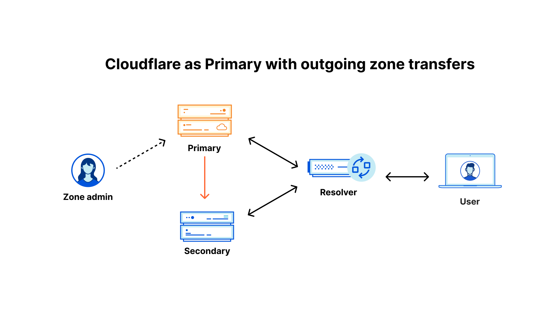
Support for outgoing zone transfers for Secondary DNS
Logpush for authoritative and secondary DNS queries
Both of them will be available as part of Foundation DNS and to enterprise customers without any additional costs. Let’s take a closer look at each of these and see how they make our DNS offering even better.
Support for outgoing zone transfers for Secondary DNS
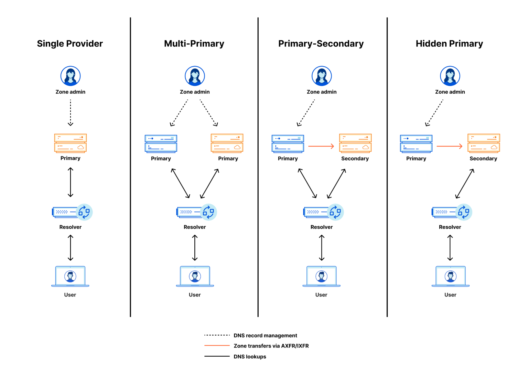
What is Secondary DNS, and why is it important? Many large enterprises have requirements to use more than one DNS provider for redundancy in case one provider becomes unavailable. They can achieve this by adding their domain’s DNS records on two independent platforms and manually keeping the zone files in sync — this is referred to as “multi-primary” setup. With Secondary DNS there are two mechanisms how this can be automated using a “primary-secondary” setup:
DNS NOTIFY: The primary nameserver notifies the secondary on every change on the zone. Once the secondary receives the NOTIFY, it sends a zone transfer request to the primary to get in sync with it.
SOA query: Here, the secondary nameserver regularly queries the SOA record of the zone and checks if the serial number that can be found on the SOA record is the same with the latest serial number the secondary has stored in it’s SOA record of the zone. If there is a new version of the zone available, it sends a zone transfer request to the primary to get those changes.
Alex Fattouche has written a very insightful blog post about how Secondary DNS works behind the scenes if you want to learn more about it. Another flavor of the primary-secondary setup is to hide the primary, thus referred to as “hidden primary”. The difference of this setup is that only the secondary nameservers are authoritative — in other words configured at the domain’s registrar. The diagram below illustrates the different setups.
Since 2018, we have been supporting primary-secondary setups where Cloudflare takes the role of the secondary nameserver. This means from our perspective that we are accepting incoming zone transfers from the primary nameservers.
Starting today, we are now also supporting outgoing zone transfers, meaning taking the role of the primary nameserver with one or multiple external secondary nameservers receiving zone transfers from Cloudflare. Exactly as for incoming transfers, we are supporting
zone transfers via AXFR and IXFR
automatic notifications via DNS NOTIFY to trigger zone transfers on every change
signed transfers using TSIG to ensure zone files are authenticated during transfer
Logpush for authoritative and secondary DNS
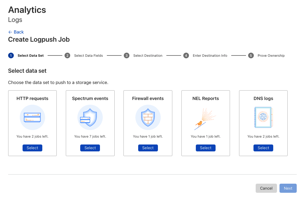
Here at Cloudflare we love logs. In Q3 2021, we processed 28 Million HTTP requests per second and 13.6 Million DNS queries per second on average and blocked 76 Billion threats each day. All these events are stored as logs for a limited time frame in order to provide our users near real-time analytics in the dashboard. For those customers who want to — or have to — permanently store these logs we’ve built Logpush back in 2019. Logpush allows you to stream logs in near real time to one of our analytics partners Microsoft Azure Sentinel, Splunk, Datadog and Sumo Logic or to any cloud storage destination with R2-compatible API.
Today, we’re adding one additional data set for Logpush: DNS logs. In order to configure Logpush and stream DNS logs for your domain, just head over to the Cloudflare dashboard, create a new Logpush job, select DNS logs and configure the log fields you’re interested in:
Check out our developer documentation for detailed instructions on how to do this through the API and for a thorough description of the new DNS log fields.
One more thing (or two…)
When looking at the entirety of DNS within your infrastructure, it’s important to review how your traffic is flowing through your systems and how that traffic is behaving. At the end of the day, there is only so much processing power, memory, server capacity, and overall compute resources available. One of the best and important tools we have available is Load Balancing and Health Monitoring!
Cloudflare has provided a Load Balancing solution since 2016, supporting customers to leverage their existing resources in a scalable and intelligent manner. But our Load Balancer was limited to A, AAAA, and CNAME records. This covered a lot of major use cases required by customers, but did not cover all of them. Many customers have more needs such as load balancing MX or email server traffic, SRV records to declare which ports and weight that respective traffic should travel across for a specific service, HTTPS records to ensure the respective traffic uses the secure protocol regardless of port and many more. We want to ensure that our customers’ needs are covered and support their ability to align business goals with technical implementation.
We are happy to announce that we have added additional Health Monitoring methods to support Load Balancing MX, SRV, HTTPS and TXT record traffic without any additional configuration necessary. Create your respective DNS records in Cloudflare and set your Load Balancer as the destination…it’s as easy as that! By leveraging ICMP Ping, SMTP, and UDP-ICMP methods, customers will always have a pulse on the health of their servers and be able to apply intelligent steering decisions based on the respective health information.
When thinking about intelligent steering, there is no one size fits all answer. Different businesses have different needs, especially when looking at where your servers are located around the globe, and where your customers are situated. A common rule of thumb to follow is to place servers where your customers are. This ensures they have the most performant and localized experience possible. One common scenario is to steer your traffic based on where your end-user request originates and create a mapping to the server closest to that area. Cloudflare’s geo steering capability allows our customers to do just that — easily create a mapping of regions to pools, ensuring if we see a request originate from Eastern Europe, to send that request to the proper server to suffice that request. But sometimes, regions can be quite large and lend to issues around not being able to tightly couple together that mapping as closely as one might like.
Today, we are very excited to announce country support within our Geo Steering functionality. Now, customers will be able to choose either one of our thirteen regions, or a specific country to map against their pools to give further granularity and control to how customers traffic should behave as it travels through their system. Both country-level steering and our new health monitoring methods to support load balancing more DNS records will be available in January 2022!
Advancing the DNS Ecosystem
Furthermore, we have some other exciting news to share: We’re finishing the work on Multi-Signer DNSSEC (RFC8901) and plan to roll this out in Q1 2022. Why is this important? Two common requirements of large enterprises are:
Redundancy: Having multiple DNS providers responding authoritatively for their domains
Authenticity: Deploying DNSSEC to ensure DNS responses can be properly authenticated
Both can be achieved by having the primary nameserver sign the domain and transfer its DNS records plus the record signatures to the secondary nameserver which will serve both as is. This setup is supported with Cloudflare Secondary DNS today. What cannot be supported when transferring pre-signed zones are non-standard DNS features like country-level steering. This is where Multi-Signer DNSSEC comes in. Both DNS providers need to know the signing keys of the other provider and perform their own online (or on-the-fly) signing. If you’re curious to learn more about how Multi-Signer DNSSEC works, go check out this excellent blog post published by APNIC.
Last but not least, Cloudflare is joining the DNS Operations, Analysis, and Research Center (DNS-OARC) as a gold member. Together with other researchers and operators of DNS infrastructure we want to tackle the most challenging problems and continuously work on implementing new standards and features.
While we’ve been at DNS since day one of Cloudflare, we’re still just getting started. We know there are more granular and specific features our future customers will ask of us and the launch of Foundation DNS is our stake in the ground that we will continue to invest in all levels of DNS while building the most feature rich enterprise DNS platform on the planet. If you have ideas, let us know what you’ve always dreamed your DNS provider would do. If you want to help build these features, we are hiring.
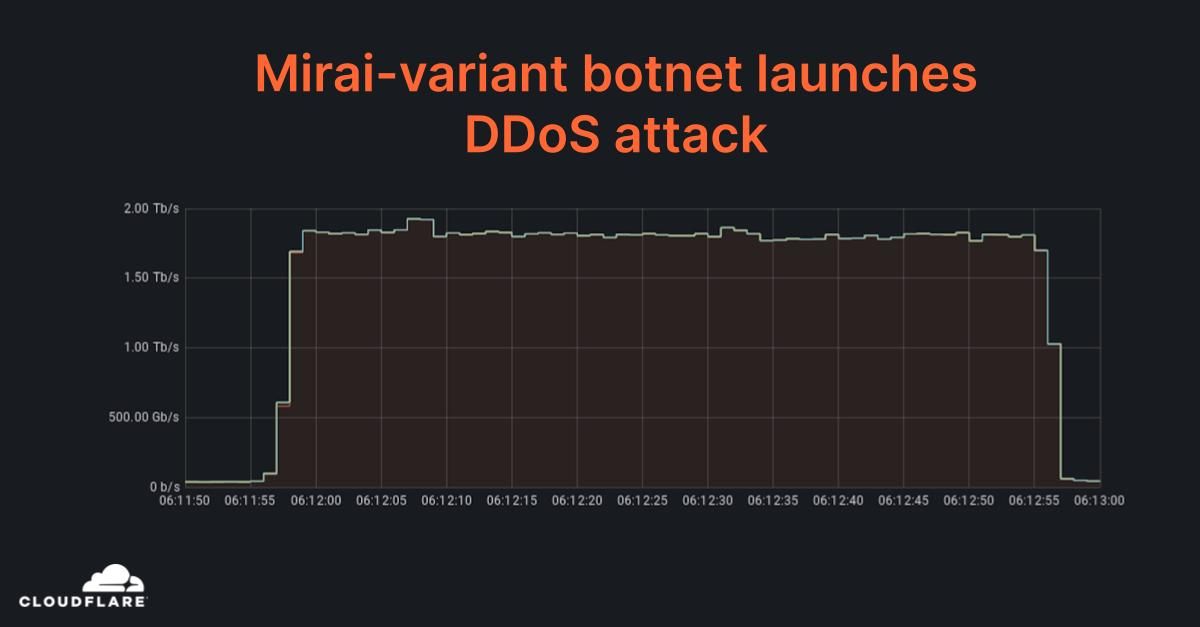
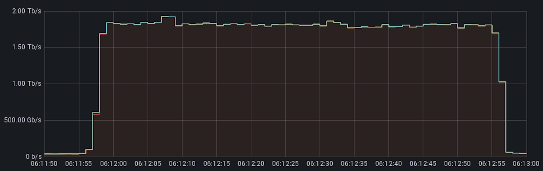
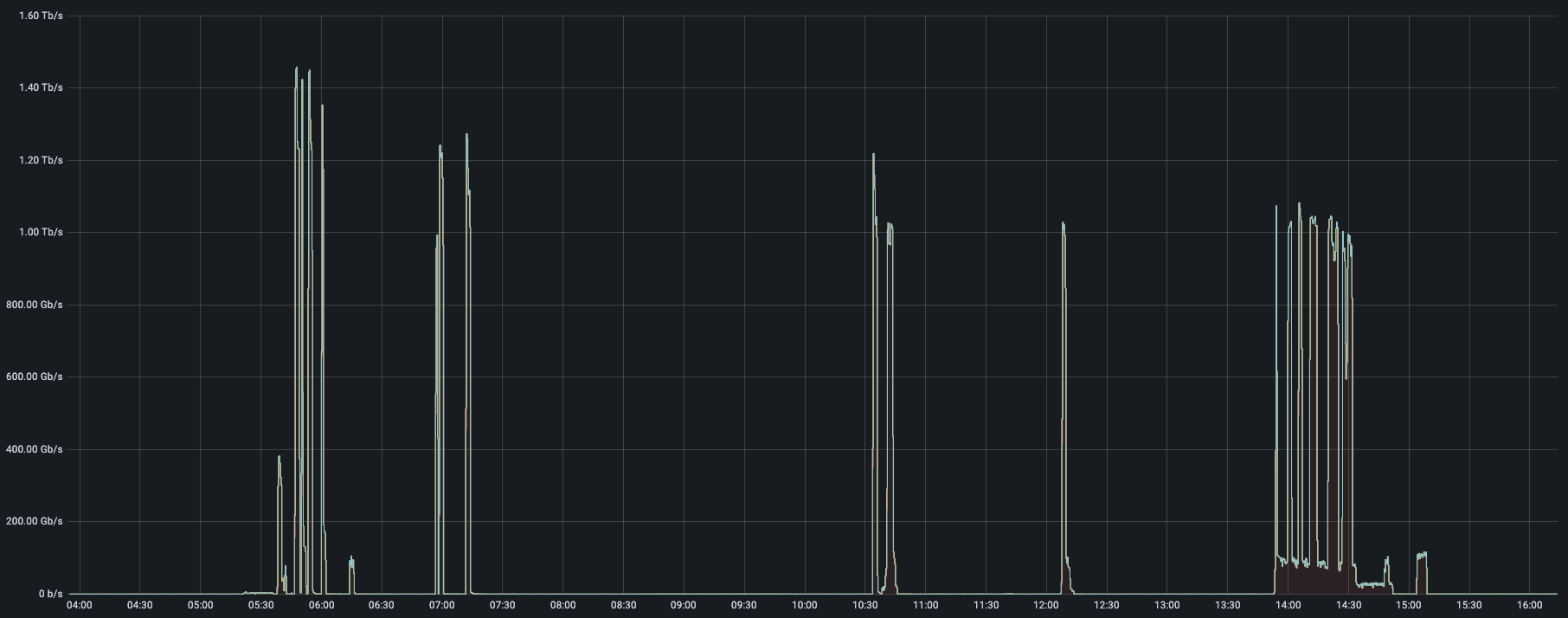
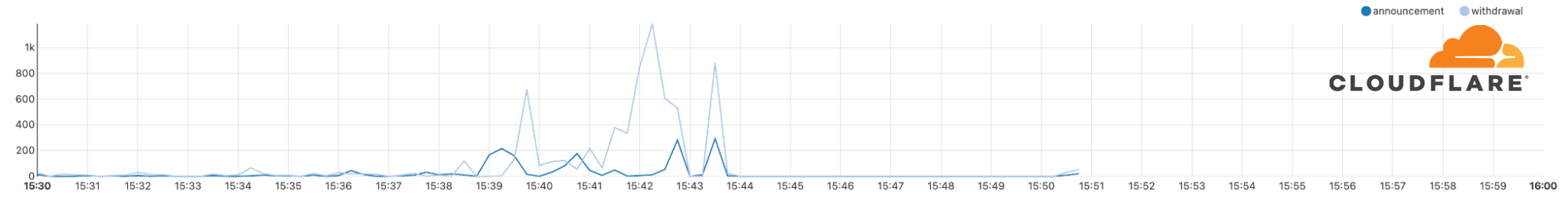
Earlier this week, Cloudflare automatically detected and mitigated a DDoS attack that peaked just below 2 Tbps — the largest we’ve seen to date. This was a multi-vector attack combining DNS amplification attacks and UDP floods. The entire attack lasted just one minute. The attack was launched from approximately 15,000 bots running a variant of the original Mirai code on IoT devices and unpatched GitLab instances.
DDoS attack peaking just below 2 Tbps
Network-layer DDoS attacks increased by 44%
Last quarter, we saw multiple terabit-strong DDoS attacks and this attack continues this trend of increased attack intensity. Another key finding from our Q3 DDoS Trends report was that network-layer DDoS attacks actually increased by 44% quarter-over-quarter. While the fourth quarter is not over yet, we have, again, seen multiple terabit-strong attacks that targeted Cloudflare customers.
DDoS attacks peaking at 1-1.4 Tbps
How did Cloudflare mitigate this attack?
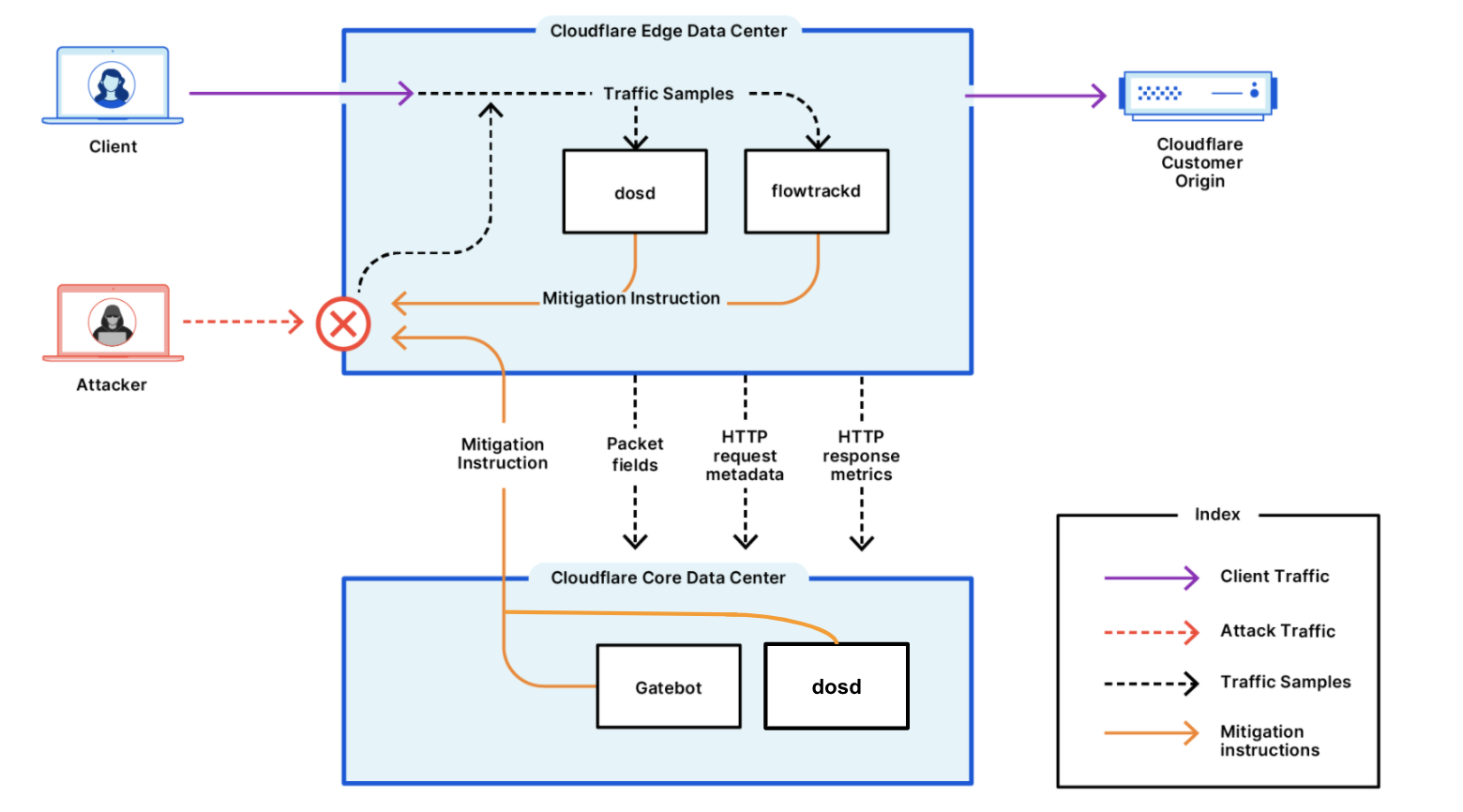
To begin with, our systems constantly analyze traffic samples “out-of-path” which allows us to asynchronously detect DDoS attacks without causing latency or impacting performance. Once the attack traffic was detected (within sub-seconds), our systems generated a real-time signature that surgically matched against the attack patterns to mitigate the attack without impacting legitimate traffic.
Once generated, the fingerprint is propagated as an ephemeral mitigation rule to the most optimal location in the Cloudflare edge for cost-efficient mitigation. In this specific case, as with most L3/4 DDoS attacks, the rule was pushed in-line into the Linux kernel eXpress Data Path (XDP) to drop the attack packet at wirespeed.
A conceptual diagram of Cloudflare’s DDoS protection systems
Cloudflare’s mission is to help build a better Internet — one that is secure, faster, and more reliable for everyone. The DDoS team’s vision is derived from this mission: our goal is to make the impact of DDoS attacks a thing of the past. Whether it’s the Meris botnet that launched some of the largest HTTP DDoS attacks on record, the recent attacks on VoIP providers or this Mirai-variant that’s DDoSing Internet properties, Cloudflare’s network automatically detects and mitigates DDoS attacks. Cloudflare provides a secure, reliable, performant, and customizable platform for Internet properties of all types.
For more information about Cloudflare’s DDoS protection, reach out to us or have a go with a hands-on evaluation of Cloudflare’s Free plan here.
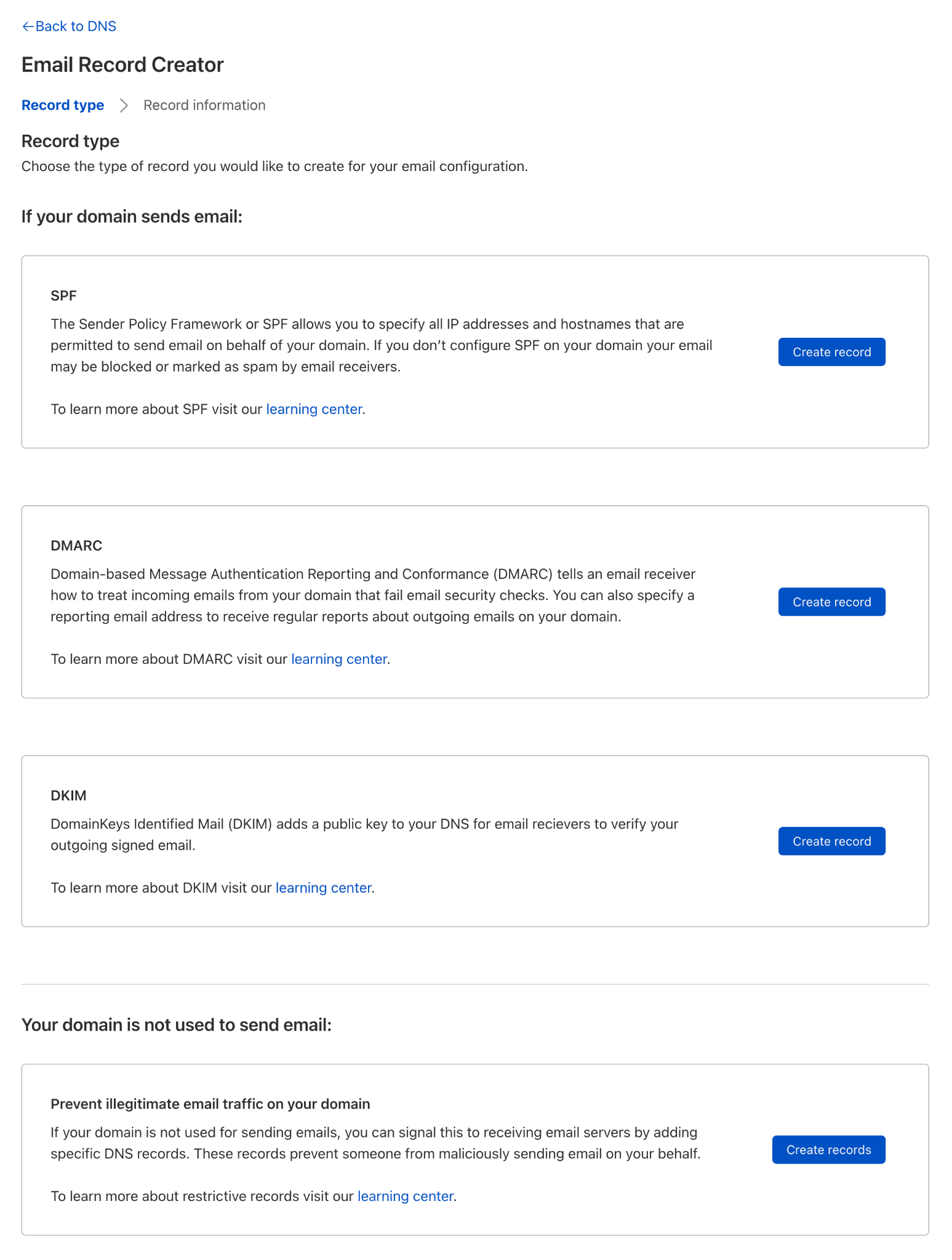
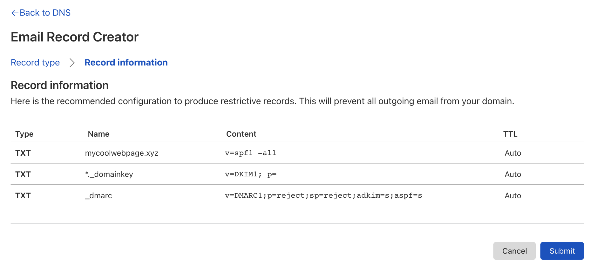
I joined Cloudflare a few weeks ago, and as someone new to the company, there’s a ton of information to absorb. I have always learned best by doing, so I decided to use Cloudflare like a brand-new user. Cloudflare customers range from individuals with a simple website to companies in the Fortune 100. I’m currently exploring Cloudflare from the perspective of the individual, so I signed up for a free account and logged into the dashboard. Just like getting into a new car, I want to turn all the dials and push all the buttons. I looked for things that would be fun and easy to do and would deliver some immediate value. Now I want to share the best ones with you.
Here are my five ways to get started with Cloudflare. These should be easy for anyone, and they’re free. You’ll likely even save some money and improve your privacy and security in the process. Let’s go!
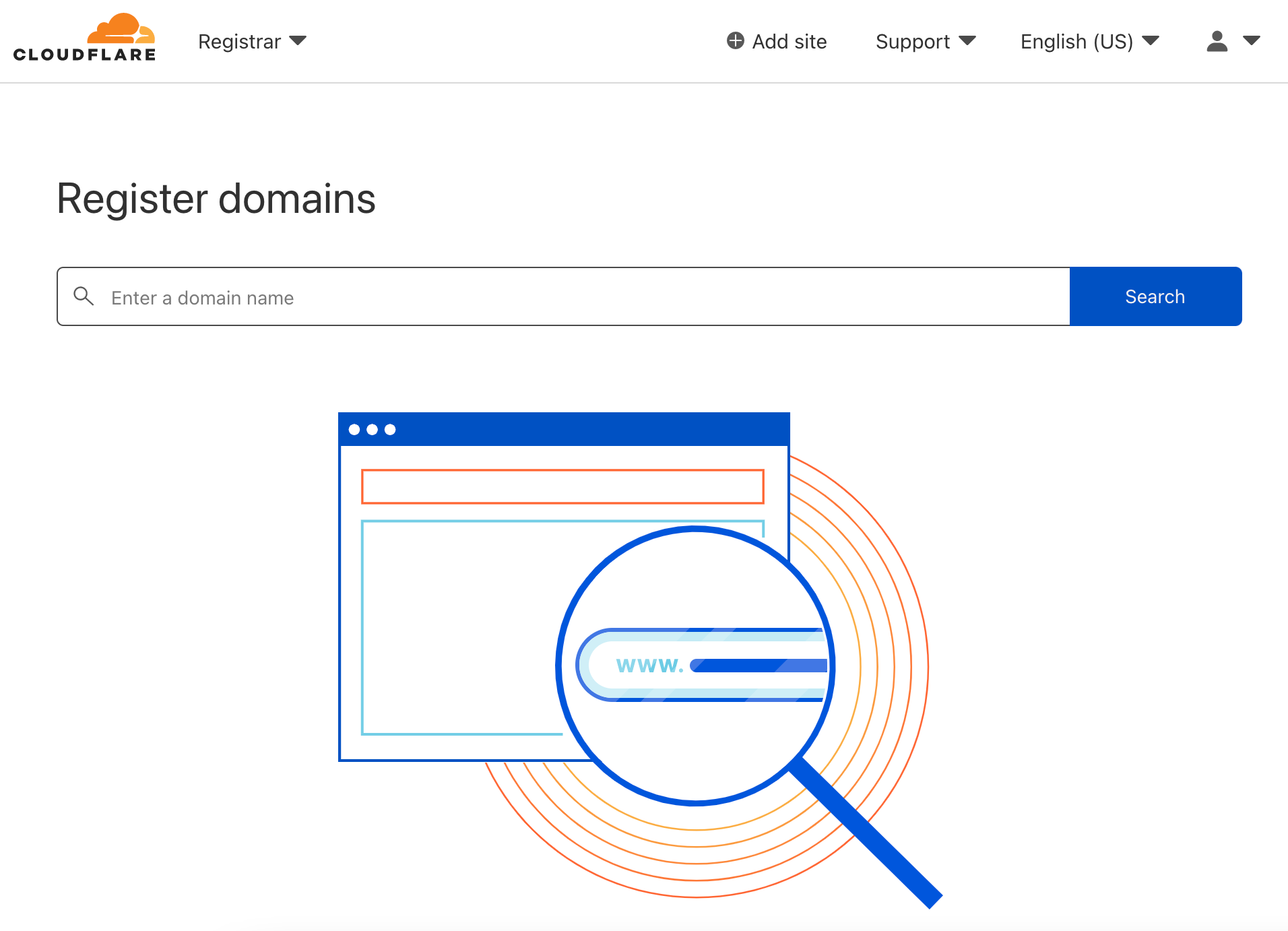
1. Transfer or register a domain with Cloudflare Registrar
If you’re like me, you’ve acquired a few (dozen) Internet domains for things like personalizing your email address, a web page for your nature photography hobby, or maybe a side business. You probably registered them at one or more of the popular domain name registrars, and you pay around $15 per year for each domain. I did an audit and found I was spending a shocking amount each year to maintain my domains, and they were spread across three different registrars.
Cloudflare makes it easy to transfer domains from other registrars and doesn’t charge a markup for domain registrar services. Let me say that again; there is zero price markup for domain registration with Cloudflare Registrar. You’ll pay exactly what Cloudflare pays. For example, a .com domain registered with Cloudflare currently costs half of what I was paying at other registrars.
Not only will you save on the domain registration, but Cloudflare doesn’t nickel-and-dime you like registrars who charge extra for WHOIS privacy and transfer lock and then sneakily bundle their website hosting services. It all adds up.
To get started registering or transferring a domain, log into the Cloudflare Dashboard, click “Add a Site,” and bring your domains to Cloudflare.
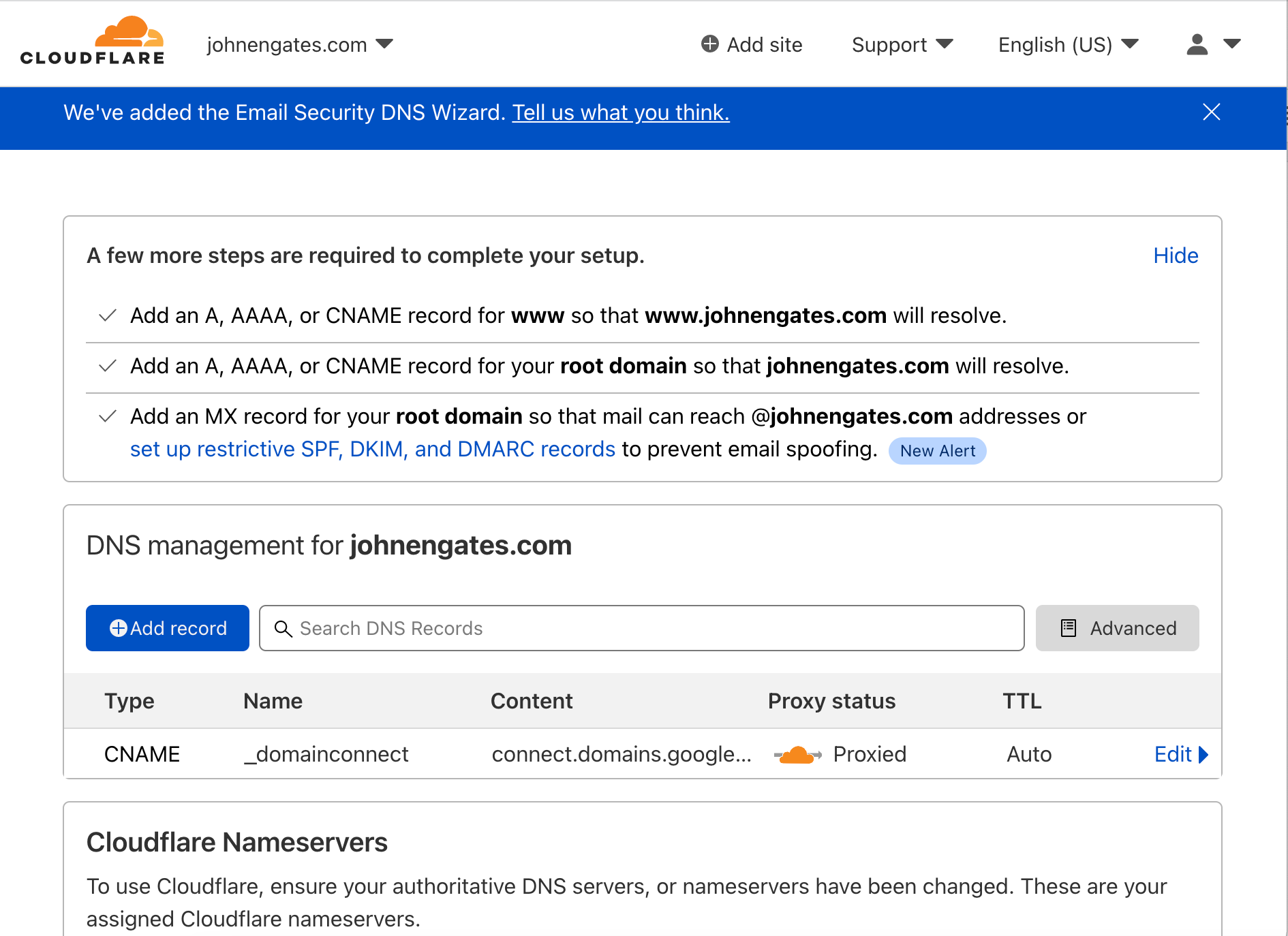
2. Configure DNS on Cloudflare DNS
DNS servers do the work of translating hostnames into IP addresses. To put a domain name to use on the Internet, you can create DNS records to point to your website and email provider. Every time someone wants to put a website or Internet application online, this process must happen so the rest of us can find it. Cloudflare’s DNS dashboard makes it simple to configure DNS records. For transfers, Cloudflare will even copy records from your existing DNS service to prevent any disruption.
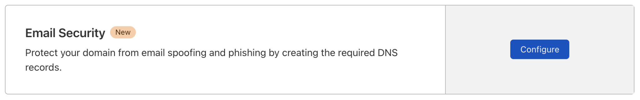
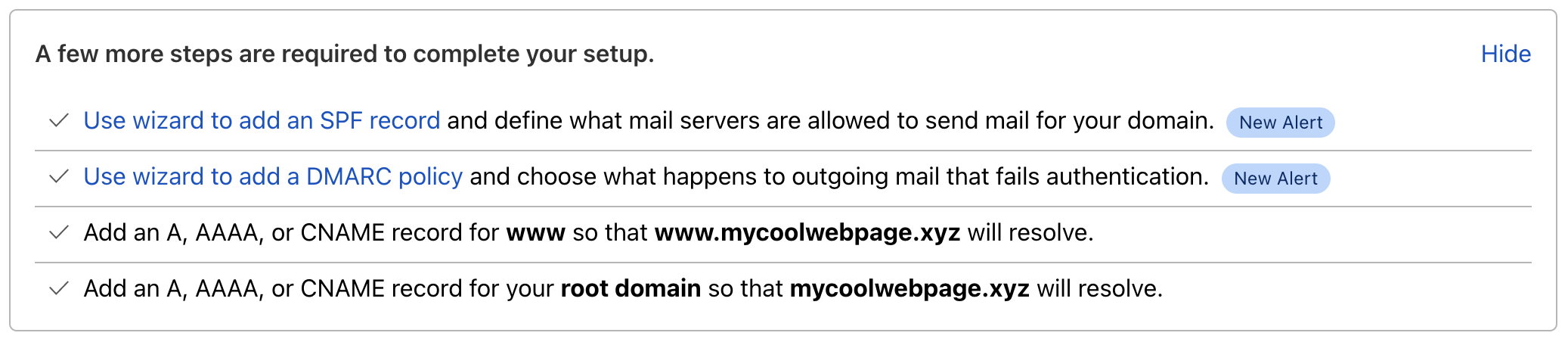
The Cloudflare DNS dashboard will also improve security on your domains with DNSSEC, protect your domains from email spoofing with DMARC, and enforce other DNS best practices.
I’ve now moved all my domains to Cloudflare DNS, which is a big win for me for security and simplicity. I can see them all in one place, and I’m more confident with the increased level of control and protection I have for my domains.
3. Set up a blog with Cloudflare Pages
Once I moved my domains, I was eager to set up a new website. I have been thinking lately it would be fun to have a place to post my photos where they can stand out and won’t get lost in the stream of social media. It’s been a while since I’ve built a website from scratch, but it’s fun getting back to basics. In the old days, to host a website you’d set up a dedicated web server or use a shared web host to serve your site. Today, many web hosts provide ready-to-go templates for websites and make hosting as easy as one click to set up a new site.
I wanted to learn by doing, so I took the do-it-yourself route. What I discovered in the process is an architecture called Jamstack. It’s a bit different from the traditional way of building and hosting websites. With Jamstack, your site doesn’t live at a traditional hosting provider, nor is it dynamically generated from CGI scripts and a database. Your content is now stored on a code repository like GitHub. The site is pre-generated as a static site and then deployed and delivered directly from Cloudflare’s network.
I used a Jamstack static site generator called Hugo to build my photo blog, pushed it to GitHub, and used Cloudflare Pages to generate the content and host my site. Now that it’s configured, there’s zero work necessary to maintain it. Jamstack, combined with Pages, alleviates the regular updates required to keep up with security patches, and there are no web servers or database services to break. Delivered from Cloudflare’s edge network, the site scales effortlessly, and it’s blazingly fast from a user perspective.
By the way, you don’t need to register a domain to deploy to Pages. Cloudflare will generate a pages.dev site that you can use.
For extra credit, have a look at the Cloudflare Workers serverless platform. Workers will allow you to write and deploy even more advanced custom code and run it across Cloudflare’s globally distributed network.
4. Protect your network with Cloudflare for Teams
At first, it wasn’t evident to me how I was going to use Cloudflare for Teams. I initially thought it was only for larger organizations. After all, I’m sitting here in my home office, and I’m just a team of one. Digging into the product more, it became clear that Teams is about privacy and security for groups of any size.
We’ve discussed the impressive Cloudflare DNS infrastructure, and you can take advantage of the Cloudflare DNS resolver for your devices at home by simply configuring them to point to Cloudflare 1.1.1.1 DNS servers. But for more granular control and detailed logging, you should try the DNS infrastructure built into the Cloudflare for Teams Gateway feature.
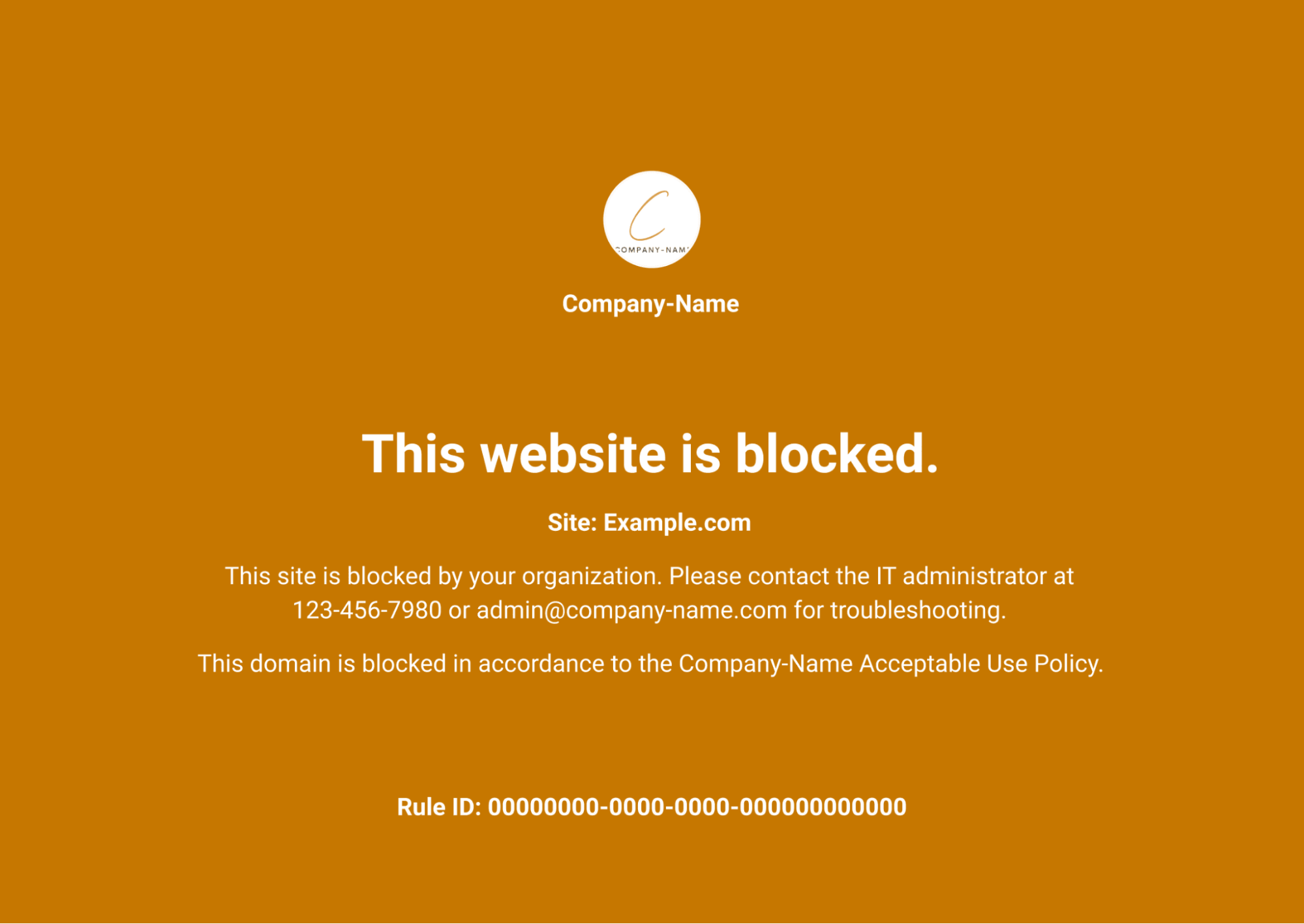
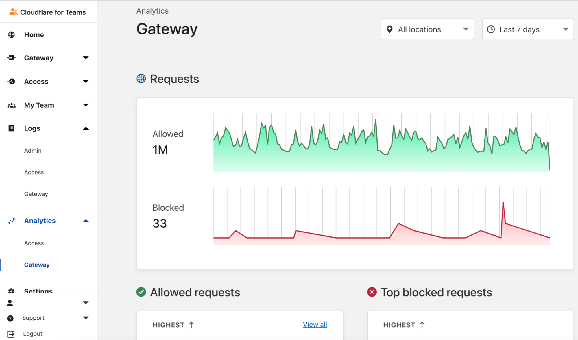
When you point your home network to Cloudflare for Teams DNS servers, your dashboard will populate with logs of all DNS requests coming from your network. You can set up rules to block DNS requests for various categories, including known malware, phishing, adult sites, and other questionable content. You’ll see the logs instantly and can add or remove categories as needed. If you trigger one of the rules, Cloudflare will display a page that shows you’ve hit one of these blocked sites.
Malware can bypass DNS, so filtering DNS is no silver bullet. Think of DNS filtering as another layer of defense that may help you avoid nefarious sites in the first place. For example, known phishing sites sent as URLs via email won’t resolve and will be blocked before they affect you. Additionally, DNS logs should give you visibility into what’s happening on the network and that may lead you to implement even better security in other areas.
There’s so much more to Cloudflare for Teams than DNS filtering, but I wanted to give you just a little taste of what you can do with it quickly and for free.
5. Secure your traffic with the Cloudflare 1.1.1.1 app and WARP
Finally, let’s discuss the challenge of securing Internet communications on your mobile phones, tablets, and devices at home and while traveling. We know that the SSL/TLS encryption on secure websites provides a degree of protection, but the apps you use and sites you visit are still visible to your ISP and upstream network operators. Some providers sell this data or use it to target you with ads.
If you install the 1.1.1.1 app, Cloudflare will create an always-on, encrypted tunnel from your device to the nearest Cloudflare data center and secure your Internet traffic. We call this Cloudflare WARP. WARP not only encrypts your traffic but can even help accelerate it by routing intelligently across the Cloudflare network.
WARP is a compelling VPN replacement without the risks associated with some shady VPN providers who may also want to sell your data. Remember, Cloudflare will never sell your data!
The Cloudflare WARP client combined with Cloudflare for Teams gives you enhanced visibility into DNS queries and unlocks some advanced traffic management and filtering capabilities. And it’s all free for small teams.
Hopefully, my exploration of the Cloudflare product portfolio gives you some ideas of what you can do to make your life a little easier or your team more secure. I’m just scratching the surface, and I’m excited to keep learning what’s possible with Cloudflare. I’ll continue to share what I learn, and I encourage you to experiment with some of these capabilities yourself and let me know how it goes.
Sometimes customers want to use their email domain with Amazon Simples Email Service (Amazon SES) across multiple accounts, or the same account but across multiple regions.
For example, AnyCompany is an insurance company with marketing and operations business units. The operations department sends transactional emails every time customers perform insurance simulations. The marketing department sends email advertisements to existing and prospective customers. Since they are different organizations inside AnyCompany, they want to have their own Amazon SES billing. At the same time, they still want to use the same AnyCompany domain.
Other use-cases include customers who want to setup multi-region redundancy, need to satisfy data residency requirements, or need to send emails on behalf of several different clients. In all of these cases, customers can use different regions, in the same or across different accounts.
This post shows how to verify and configure your domain on Amazon SES across multiple accounts or multiple regions.
Overview of solution
You can use the same domain with Amazon SES across multiple accounts or regions. Your options are: different accounts but the same region, different accounts and different regions, and the same account but different regions.
In all of these scenarios, you will have two SES instances running, each sending email for example.com domain – let’s call them SES1 and SES2. Every time you configure a domain in Amazon SES it will generate a series of DNS records you will have to add on your domain authoritative DNS server, which is unique for your domain. Those records are different for each SES instance.
You will need to modify your DNS to add one TXT record, with multiple values, for domain verification. If you decide to use DomainKeys Identified Mail (DKIM), you will modify your DNS to add six CNAME records, three records from each SES instance.
When you configure a domain on Amazon SES, you can also configure a MAIL FROM domain. If you decide to do so, you will need to modify your DNS to add one TXT record for Sender Policy Framework (SPF) and one MX record for bounce and complaint notifications that email providers send you.
Furthermore, your domain can be configured to support DMAC for email spoofing detection. It will rely on SPF or DKIM configured above. Below we walk you through these steps.
Verify domain You will take TXT values from both SES1 and SES2 instances and add them in DNS, so SES can validate you own the domain
Verify DomainKeys Identified Mail (DKIM) You will take CNAME values from both SES1 and SES2 instances and add them in DNS, so SES can verify DKIM for your domain
Complying with DMAC You will add a TXT value with DMAC policy that applies to your domain. This is not tied to any specific SES instance
Custom MAIL FROM Domain and SPF You will take TXT and MX records related from your MAIL FROM domain from both SES1 and SES2 instances and add them in DNS, so SES can comply with DMARC
Here is a sample matrix of the various configurations:
Two accounts, same region
Two accounts, different regions
One account, two regions
TXT records for domain verification*
1 record with multiple values
_amazonses.example.com = “VALUE FROM SES1” “VALUE FROM SES2”
CNAMES for DKIM verification
6 records, 3 from each SES instance
record1-SES1._domainkey.example.com = VALUE FROM SES1 record2-SES1._domainkey.example.com = VALUE FROM SES1 record3-SES1._domainkey.example.com = VALUE FROM SES1 record1-SES2._domainkey.example.com = VALUE FROM SES2 record2-SES2._domainkey.example.com = VALUE FROM SES2 record3-SES2._domainkey.example.com = VALUE FROM SES2
TXT record for DMARC
1 record. It is not related to SES instance or region
_dmarc.example.com = DMARC VALUE
MAIL FROM MX record to define message sender for SES
* Considering your DNS supports multiple values for a TXT record
Setup SES1 and SES2
In this blog, we call SES1 your primary or existing SES instance. We assume that you have already setup SES, but if not, you can still follow the instructions and setup both at the same time. The settings on SES2 will differ slightly, and therefore you will need to add new DNS entries to support the two-instance setup.
In this document we will use configurations from the “Verification,” “DKIM,” and “Mail FROM Domain” sections of the SES Domains screen and configure SES2 and setup DNS correctly for the two-instance configuration.
Verify domain
Amazon SES requires that you verify, in DNS, your domain, to confirm that you own it and to prevent others from using it. When you verify an entire domain, you are verifying all email addresses from that domain, so you don’t need to verify email addresses from that domain individually.
You can instruct multiple SES instances, across multiple accounts or regions to verify your domain. The process to verify your domain requires you to add some records in your DNS provider. In this post I am assuming Amazon Route 53 is an authoritative DNS server for example.com domain.
Verifying a domain for SES purposes involves initiating the verification in SES console, and adding DNS records and values to confirm you have ownership of the domain. SES will automatically check DNS to complete the verification process. We assume you have done this step for SES1 instance, and have a _amazonses.example.com TXT record with one value already in your DNS. In this section you will add a second value, from SES2, to the TXT record. If you do not have SES1 setup in DNS, complete these steps twice, once for SES1 and again for SES2. This will prove to both SES instances that you own the domain and are entitled to send email from them.
Initiate Verification in SES Console
Just like you have done on SES1, in the second SES instance (SES2) initiate a verification process for the same domain; in our case example.com
In the navigation pane, under Identity Management, choose Domains.
Choose Verify a New Domain.
In the Verify a New Domain dialog box, enter the domain name (i.e. example.com).
If you want to set up DKIM signing for this domain, choose Generate DKIM Settings.
Click on Verify This Domain.
In the Verify a New Domain dialog box, you will see a Domain Verification Record Set containing a Name, a Type, and a Value. Copy Name and Value and store them for the step below, where you will add this value to DNS. (This information is also available by choosing the domain name after you close the dialog box.)
To complete domain verification, add a TXT record with the displayed Name and Value to your domain’s DNS server. For information about Amazon SES TXT records and general guidance about how to add a TXT record to a DNS server, see Amazon SES domain verification TXT records.
Add DNS Values for SES2
To complete domain verification for your second account, edit current _amazonses TXT record and add the Value from the SES2 to it. If you do not have an _amazonses TXT record create it, and add the Domain Verification values from both SES1 and SES2 to it. We are showing how to add record to Route 53 DNS, but the steps should be similar in any DNS management service you use.
Choose the _amazonses TXT record you created when you verified your domain for SES1.
Under Record details, choose Edit record.
In the Value box, go to the end of the existing attribute value, and then press Enter.
Add the attribute value for the additional account or region.
Choose Save.
To validate, run the following command: dig TXT _amazonses.example.com +short
You should see the two values returned: "4AjLMzUu4nSjrz4QVqDD8rXq8X2AHr+JhGSl4foiMmU=" "abcde12345Sjrz4QVqDD8rXq8X2AHr+JhGSl4foiMmU="
Please note:
if your DNS provider does not allow underscores in record names, you can omit _amazonses from the Name.
to help you easily identify this record within your domain’s DNS settings, you can optionally prefix the Value with “amazonses:”.
some DNS providers automatically append the domain name to DNS record names. To avoid duplication of the domain name, you can add a period to the end of the domain name in the DNS record. This indicates that the record name is fully qualified and the DNS provider need not append an additional domain name.
if your DNS server does not support two values for a TXT record, you can have one record named _amazonses.example.com and another one called example.com.
Finally, after some time SES will complete its validation of the domain name and you should see the “pending validation” change to “verified”.
Verify DKIM
DomainKeys Identified Mail (DKIM) is a standard that allows senders to sign their email messages with a cryptographic key. Email providers then use these signatures to verify that the messages weren’t modified by a third party while in transit.
An email message that is sent using DKIM includes a DKIM-Signature header field that contains a cryptographically signed representation of the message. A provider that receives the message can use a public key, which is published in the sender’s DNS record, to decode the signature. Email providers then use this information to determine whether messages are authentic.
When you enable DKIM it generates CNAME records you need to add into your DNS. As it generates different values for each SES instance, you can use DKIM with multiple accounts and regions.
To complete the DKIM verification, copy the three (3) DKIM Names and Values from SES1 and three (3) from SES2 and add them to your DNS authoritative server as CNAME records.
You will know you are successful because, after some time SES will complete the DKIM verification and the “pending verification” will change to “verified”.
Configuring for DMARC compliance
Domain-based Message Authentication, Reporting and Conformance (DMARC) is an email authentication protocol that uses Sender Policy Framework (SPF) and/or DomainKeys Identified Mail (DKIM) to detect email spoofing. In order to comply with DMARC, you need to setup a “_dmarc” DNS record and either SPF or DKIM, or both. The DNS record for compliance with DMARC is setup once per domain, but SPF and DKIM require DNS records for each SES instance.
Setup “_dmarc” record in DNS for your domain; one time per domain. See instructions here
To validate it, run the following command: dig TXT _dmarc.example.com +short "v=DMARC1;p=quarantine;pct=25;rua=mailto:[email protected]"
For DKIM and SPF follow the instructions below
Custom MAIL FROM Domain and SPF
Sender Policy Framework (SPF) is an email validation standard that’s designed to prevent email spoofing. Domain owners use SPF to tell email providers which servers are allowed to send email from their domains. SPF is defined in RFC 7208.
To comply with Sender Policy Framework (SPF) you will need to use a custom MAIL FROM domain. When you enable MAIL FROM domain in SES console, the service generates two records you need to configure in your DNS to document who is authorized to send messages for your domain. One record is MX and another TXT; see screenshot for mail.example.com. Save these records and enter them in your DNS authoritative server for example.com.
In the navigation pane, under Identity Management, choose Domains.
In the list of domains, choose the domain and proceed to the next step.
Under MAIL FROM Domain, choose Set MAIL FROM Domain.
On the Set MAIL FROM Domain window, do the following:
For MAIL FROM domain, enter the subdomain that you want to use as the MAIL FROM domain. In our case mail.example.com.
For Behavior if MX record not found, choose one of the following options:
Use amazonses.com as MAIL FROM – If the custom MAIL FROM domain’s MX record is not set up correctly, Amazon SES will use a subdomain of amazonses.com. The subdomain varies based on the AWS Region in which you use Amazon SES.
Reject message – If the custom MAIL FROM domain’s MX record is not set up correctly, Amazon SES will return a MailFromDomainNotVerified error. Emails that you attempt to send from this domain will be automatically rejected.
Click Set MAIL FROM Domain.
You will need to complete this step on SES1, as well as SES2. The MAIL FROM records are regional and you will need to add them both to your DNS authoritative server.
Set MAIL FROM records in DNS
From both SES1 and SES2, take the MX and TXT records provided by the MAIL FROM configuration and add them to the DNS authoritative server. If SES1 and SES2 are in the same region (us-east-1 in our example) you will publish exactly one MX record (mail.example.com in our example) into DNS, pointing to endpoint for that region. If SES1 and SES2 are in different regions, you will create two different records (mail1.example.com and mail2.example.com) into DNS, each pointing to endpoint for specific region.
Verify MX record
Example of MX record where SES1 and SES2 are in the same region
On both SES instances (SES1 and SES2), check that validations are complete. In the SES Console:
In Verification section, Status should be “verified” (in green color)
In DKIM section, DKIM Verification Status should be “verified” (in green color)
In MAIL FROM Domain section, MAIL FROM domain status should be “verified” (in green color)
If you have it all verified on both accounts or regions, it is correctly configured and ready to use.
Conclusion
In this post, we explained how to verify and use the same domain for Amazon SES in multiple account and regions and maintaining the DMARC, DKIM and SPF compliance and security features related to email exchange.
While each customer has different necessities, Amazon SES is flexible to allow customers decide, organize, and be in control about how they want to uses Amazon SES to send email.
Author bio
Leonardo Azize Martins is a Cloud Infrastructure Architect at Professional Services for Public Sector.
His background is on development and infrastructure for web applications, working on large enterprises.
When not working, Leonardo enjoys time with family, read technical content, watch movies and series, and play with his daughter.
Contributor
Daniel Tet is a senior solutions architect at AWS specializing in Low-Code and No-Code solutions. For over twenty years, he has worked on projects for Franklin Templeton, Blackrock, Stanford Children’s Hospital, Napster, and Twitter. He has a Bachelor of Science in Computer Science and an MBA. He is passionate about making technology easy for common people; he enjoys camping and adventures in nature.
It’s been a few days now since Facebook, Instagram, and WhatsApp went AWOL and experienced one of the most extended and rough downtime periods in their existence.
When that happened, we reported our bird’s-eye view of the event and posted the blog Understanding How Facebook Disappeared from the Internet where we tried to explain what we saw and how DNS and BGP, two of the technologies at the center of the outage, played a role in the event.
In the meantime, more information has surfaced, and Facebook has published a blog post giving more details of what happened internally.
As we said before, these events are a gentle reminder that the Internet is a vast network of networks, and we, as industry players and end-users, are part of it and should work together.
In the aftermath of an event of this size, we don’t waste much time debating how peers handled the situation. We do, however, ask ourselves the more important questions: “How did this affect us?” and “What if this had happened to us?” Asking and answering these questions whenever something like this happens is a great and healthy exercise that helps us improve our own resilience.
Today, we’re going to show you how the Facebook and affiliate sites downtime affected us, and what we can see in our data.
1.1.1.1
1.1.1.1 is a fast and privacy-centric public DNS resolver operated by Cloudflare, used by millions of users, browsers, and devices worldwide. Let’s look at our telemetry and see what we find.
First, the obvious. If we look at the response rate, there was a massive spike in the number of SERVFAIL codes. SERVFAILs can happen for several reasons; we have an excellent blog called Unwrap the SERVFAIL that you should read if you’re curious.
In this case, we started serving SERVFAIL responses to all facebook.com and whatsapp.com DNS queries because our resolver couldn’t access the upstream Facebook authoritative servers. About 60x times more than the average on a typical day.
If we look at all the queries, not specific to Facebook or WhatsApp domains, and we split them by IPv4 and IPv6 clients, we can see that our load increased too.
As explained before, this is due to a snowball effect associated with applications and users retrying after the errors and generating even more traffic. In this case, 1.1.1.1 had to handle more than the expected rate for A and AAAA queries.
Here’s another fun one.
DNS vs. DoT and DoH. Typically, DNS queries and responses are sent in plaintext over UDP (or TCP sometimes), and that’s been the case for decades now. Naturally, this poses security and privacy risks to end-users as it allows in-transit attacks or traffic snooping.
With DNS over TLS (DoT) and DNS over HTTPS, clients can talk DNS using well-known, well-supported encryption and authentication protocols.
Our learning center has a good article on “DNS over TLS vs. DNS over HTTPS” that you can read. Browsers like Chrome, Firefox, and Edge have supported DoH for some time now, WAP uses DoH too, and you can even configure your operating system to use the new protocols.
When Facebook went offline, we saw the number of DoT+DoH SERVFAILs responses grow by over x300 vs. the average rate.
So, we got hammered with lots of requests and errors, causing traffic spikes to our 1.1.1.1 resolver and causing an unexpected load in the edge network and systems. How did we perform during this stressful period?
Quite well. 1.1.1.1 kept its cool and continued serving the vast majority of requests around the famous 10ms mark. An insignificant fraction of p95 and p99 percentiles saw increased response times, probably due to timeouts trying to reach Facebook’s nameservers.
Another interesting perspective is the distribution of the ratio between SERVFAIL and good DNS answers, by country. In theory, the higher this ratio is, the more the country uses Facebook. Here’s the map with the countries that suffered the most:
Here’s the top twelve country list, ordered by those that apparently use Facebook, WhatsApp and Instagram the most:
Country
SERVFAIL/Good Answers ratio
Turkey
7.34
Grenada
4.84
Congo
4.44
Lesotho
3.94
Nicaragua
3.57
South Sudan
3.47
Syrian Arab Republic
3.41
Serbia
3.25
Turkmenistan
3.23
United Arab Emirates
3.17
Togo
3.14
French Guiana
3.00
Impact on other sites
When Facebook, Instagram, and WhatsApp aren’t around, the world turns to other places to look for information on what’s going on, other forms of entertainment or other applications to communicate with their friends and family. Our data shows us those shifts. While Facebook was going down, other services and platforms were going up.
To get an idea of the changing traffic patterns we look at DNS queries as an indicator of increased traffic to specific sites or types of site.
Here are a few examples.
Other social media platforms saw a slight increase in use, compared to normal.
Traffic to messaging platforms like Telegram, Signal, Discord and Slack got a little push too.
Nothing like a little gaming time when Instagram is down, we guess, when looking at traffic to sites like Steam, Xbox, Minecraft and others.
And yes, people want to know what’s going on and fall back on news sites like CNN, New York Times, The Guardian, Wall Street Journal, Washington Post, Huffington Post, BBC, and others:
Attacks
One could speculate that the Internet was under attack from malicious hackers. Our Firewall doesn’t agree; nothing out of the ordinary stands out.
Network Error Logs
Network Error Logging, NEL for short, is an experimental technology supported in Chrome. A website can issue a Report-To header and ask the browser to send reports about network problems, like bad requests or DNS issues, to a specific endpoint.
Cloudflare uses NEL data to quickly help triage end-user connectivity issues when end-users reach our network. You can learn more about this feature in our help center.
If Facebook is down and their DNS isn’t responding, Chrome will start reporting NEL events every time one of the pages in our zones fails to load Facebook comments, posts, ads, or authentication buttons. This chart shows it clearly.
WARP
Cloudflare announced WARP in 2019, and called it “A VPN for People Who Don’t Know What V.P.N. Stands For” and offered it for free to its customers. Today WARP is used by millions of people worldwide to securely and privately access the Internet on their desktop and mobile devices. Here’s what we saw during the outage by looking at traffic volume between WARP and Facebook’s network:
You can see how the steep drop in Facebook ASN traffic coincides with the start of the incident and how it compares to the same period the day before.
Our own traffic
People tend to think of Facebook as a place to visit. We log in, and we access Facebook, we post. It turns out that Facebook likes to visit us too, quite a lot. Like Google and other platforms, Facebook uses an army of crawlers to constantly check websites for data and updates. Those robots gather information about websites content, such as its titles, descriptions, thumbnail images, and metadata. You can learn more about this on the “The Facebook Crawler” page and the Open Graph website.
Here’s what we see when traffic is coming from the Facebook ASN, supposedly from crawlers, to our CDN sites:
The robots went silent.
What about the traffic coming to our CDN sites from Facebook User-Agents? The gap is indisputable.
We see about 30% of a typical request rate hitting us. But it’s not zero; why is that?
We’ll let you know a little secret. Never trust User-Agent information; it’s broken. User-Agent spoofing is everywhere. Browsers, apps, and other clients deliberately change the User-Agent string when they fetch pages from the Internet to hide, obtain access to certain features, or bypass paywalls (because pay-walled sites want sites like Facebook to index their content, so that then they get more traffic from links).
Fortunately, there are newer, and privacy-centric standards emerging like User-Agent Client Hints.
Core Web Vitals
Core Web Vitals are the subset of Web Vitals, an initiative by Google to provide a unified interface to measure real-world quality signals when a user visits a web page. Such signals include Largest Contentful Paint (LCP), First Input Delay (FID), and Cumulative Layout Shift (CLS).
We use Core Web Vitals with our privacy-centric Web Analytics product and collect anonymized data on how end-users experience the websites that enable this feature.
One of the metrics we can calculate using these signals is the page load time. Our theory is that if a page includes scripts coming from external sites (for example, Facebook “like” buttons, comments, ads), and they are unreachable, its total load time gets affected.
We used a list of about 400 domains that we know embed Facebook scripts in their pages and looked at the data.
Now let’s look at the Largest Contentful Paint. LCP marks the point in the page load timeline when the page’s main content has likely loaded. The faster the LCP is, the better the end-user experience.
Again, the page load experience got visibly degraded.
The outcome seems clear. The sites that use Facebook scripts in their pages took 1.5x more time to load their pages during the outage, with some of them taking more than 2x the usual time. Facebook’s outage dragged the performance of some other sites down.
Conclusion
When Facebook, Instagram, and WhatsApp went down, the Web felt it. Some websites got slower or lost traffic, other services and platforms got unexpected load, and people lost the ability to communicate or do business normally.
Facebook was down. I’d recommend reading Cloudflare’s summary. Then I recommend reading Facebook’s own account on the incident. But let me expand on that. Facebook published announcements and withdrawals for certain BGP prefixes which lead to removing its DNS servers from “the map of the internet” – they told everyone “the part of our network where our DNS servers are doesn’t exist”. That was the result of a backbone self-inflicted failure due to a bug in the auditing tool that checks whether the commands executed aren’t doing harmful things.
Facebook owns a lot of IPs. According to RIPEstat they are part of 399 prefixes (147 of them are IPv4). The DNS servers are located in two of those 399. Facebook uses a.ns.facebook.com, b.ns.facebook.com, c.ns.facebook.com and d.ns.facebook.com, which get queries whenever someone wants to know the IPs of Facebook-owned domains. These four nameservers are served by the same Autonomous System from just two prefixes – 129.134.30.0/23 and 185.89.218.0/23. Of course “4 nameservers” is a logical construct, there are probably many actual servers behind that (using anycast).
I wrote a simple “script” to fetch all the withdrawals and announcements for all Facebook-owned prefixes (from the great API of RIPEstats). Facebook didn’t remove itself from the map entirely. As CloudFlare points out, it was just some prefixes that are affected. It can be just these two, or a few others as well, but it seems that just a handful were affected. If we sort the resulting CSV from the above script by withdrawals, we’ll notice that 129.134.30.0/23 and 185.89.218.0/23 are the pretty high up (alongside 185.89 and 123.134 with a /24, which are all included in the /23). Now that perfectly matches Facebook’s account that their nameservers automatically withdraw themselves if they fail to connect to other parts of the infrastructure. Everything may have also been down, but the logic for withdrawal is present only in the networks that have nameservers in them.
So first, let me make three general observations that are not as obvious and as universal as they may sound, but they are worth discussing:
Use longer DNS TTLs if possible – if Facebook had 6 hour TTL on its domains, we may have not figured out that their name servers are down. This is hard to ask for such a complex service that uses DNS for load-balancing and geographical distribution, but it’s worth considering. Also, if they killed their backbone and their entire infrastructure was down anyway, the DNS TTL would not have solved the issue. But
We need improved caching logic for DNS. It can’t be just “present or not”; DNS caches may keep “last known good state” in case of SERVFAIL and fallback to that. All of those DNS resolvers that had to ask the authoritative nameserver “where can I find facebook.com” knew where to find facebook.com just a minute ago. Then they got a failure and suddenly they are wondering “oh, where could Facebook be?”. It’s not that simple, of course, but such cache improvement is worth considering. And again, if their entire infrastructure was down, this would not have helped.
Consider having an authoritative nameserver outside your main AS. If something bad happens to your AS routes (regardless of the reason), you may still have DNS working. That may have downsides – generally, it will be hard to manage and sync your DNS infrastructure. But at least having a spare set of nameservers and the option to quickly point glue records there is worth considering. It would not have saved Facebook in this case, as again, they claim the entire infrastructure was inaccessible due to a “broken” backbone.
Have a 100% test coverage on critical tools, such as the auditing tool that had a bug. 100% test coverage is rarely achievable in any project, but in such critical tools it’s a must.
The main explanation is the accidental outage. This is what Facebook engineers explain in the blogpost and other accounts, and that’s what seems to have happened. However, there are alternative hypotheses floating around, so let me briefly discuss all of the options.
Accidental outage due to misconfiguration – a very likely scenario. These things may happen to everyone and Facebook is known for it “break things” mentality, so it’s not unlikely that they just didn’t have the right safeguards in place and that someone ran a buggy update. The scenarios why and how that may have happened are many, and we can’t know from the outside (even after Facebook’s brief description). This remains the primary explanation, following my favorite Hanlon’s razor. A bug in the audit tool is absolutely realistic (btw, I’d love Facebook to publish their internal tools).
Cyber attack – It cannot be known by the data we have, but this would be a sophisticated attack that gained access to their BGP administration interface, which I would assume is properly protected. Not impossible, but a 6-hour outage of a social network is not something a sophisticated actor (e.g. a nation state) would invest resources in. We can’t rule it out, as this might be “just a drill” for something bigger to follow. If I were an attacker that wanted to take Facebook down, I’d try to kill their DNS servers, or indeed, “de-route” them. If we didn’t know that Facebook lets its DNS servers cut themselves from the network in case of failures, the fact that so few prefixes were updated might be in indicator of targeted attack, but this seems less and less likely.
Deliberate self-sabotage – 1.5 billion records are claimed to be leaked yesterday. At the same time, a Facebook whistleblower is testifying in the US congress. Both of these news are potentially damaging to Facebook reputation and shares. If they wanted to drown the news and the respective share price plunge in a technical story that few people understand but everyone is talking about (and then have their share price rebound, because technical issues happen to everyone), then that’s the way to do it – just as a malicious actor would do, but without all the hassle to gain access from outside – de-route the prefixes for the DNS servers and you have a “perfect” outage. These coincidences have lead people to assume such a plot, but from the observed outage and the explanation given by Facebook on why the DNS prefixes have been automatically withdrawn, this sounds unlikely.
Distinguishing between the three options is actually hard. You can mask a deliberate outage as an accident, a malicious actor can make it look like a deliberate self-sabotage. That’s why there are speculations. To me, however, by all of the data we have in RIPEStat and the various accounts by CloudFlare, Facebook and other experts, it seems that a chain of mistakes (operational and possibly design ones) lead to this.
Facebook — along with Instagram and WhatsApp — went down globally today. Basically, someone deleted their BGP records, which made their DNS fall apart.
…at approximately 11:39 a.m. ET today (15:39 UTC), someone at Facebook caused an update to be made to the company’s Border Gateway Protocol (BGP) records. BGP is a mechanism by which Internet service providers of the world share information about which providers are responsible for routing Internet traffic to which specific groups of Internet addresses.
In simpler terms, sometime this morning Facebook took away the map telling the world’s computers how to find its various online properties. As a result, when one types Facebook.com into a web browser, the browser has no idea where to find Facebook.com, and so returns an error page.
In addition to stranding billions of users, the Facebook outage also has stranded its employees from communicating with one another using their internal Facebook tools. That’s because Facebook’s email and tools are all managed in house and via the same domains that are now stranded.
What I heard is that none of the employee keycards work, since they have to ping a now-unreachable server. So people can’t get into buildings and offices.
And every third-party site that relies on “log in with Facebook” is stuck as well.
As a former network admin who worked on the internet at this level, I anticipate Facebook will be down for hours more. I suspect it will end up being Facebook’s longest and most severe failure to date before it’s fixed.
“Facebook can’t be down, can it?”, we thought, for a second.
Today at 1651 UTC, we opened an internal incident entitled “Facebook DNS lookup returning SERVFAIL” because we were worried that something was wrong with our DNS resolver 1.1.1.1. But as we were about to post on our public status page we realized something else more serious was going on.
Social media quickly burst into flames, reporting what our engineers rapidly confirmed too. Facebook and its affiliated services WhatsApp and Instagram were, in fact, all down. Their DNS names stopped resolving, and their infrastructure IPs were unreachable. It was as if someone had “pulled the cables” from their data centers all at once and disconnected them from the Internet.
How’s that even possible?
Meet BGP
BGP stands for Border Gateway Protocol. It’s a mechanism to exchange routing information between autonomous systems (AS) on the Internet. The big routers that make the Internet work have huge, constantly updated lists of the possible routes that can be used to deliver every network packet to their final destinations. Without BGP, the Internet routers wouldn’t know what to do, and the Internet wouldn’t work.
The Internet is literally a network of networks, and it’s bound together by BGP. BGP allows one network (say Facebook) to advertise its presence to other networks that form the Internet. As we write Facebook is not advertising its presence, ISPs and other networks can’t find Facebook’s network and so it is unavailable.
The individual networks each have an ASN: an Autonomous System Number. An Autonomous System (AS) is an individual network with a unified internal routing policy. An AS can originate prefixes (say that they control a group of IP addresses), as well as transit prefixes (say they know how to reach specific groups of IP addresses).
Cloudflare’s ASN is AS13335. Every ASN needs to announce its prefix routes to the Internet using BGP; otherwise, no one will know how to connect and where to find us.
In this simplified diagram, you can see six autonomous systems on the Internet and two possible routes that one packet can use to go from Start to End. AS1 → AS2 → AS3 being the fastest, and AS1 → AS6 → AS5 → AS4 → AS3 being the slowest, but that can be used if the first fails.
At 1658 UTC we noticed that Facebook had stopped announcing the routes to their DNS prefixes. That meant that, at least, Facebook’s DNS servers were unavailable. Because of this Cloudflare’s 1.1.1.1 DNS resolver could no longer respond to queries asking for the IP address of facebook.com or instagram.com.
route-views>show ip bgp 185.89.218.0/23
% Network not in table
route-views>

route-views>show ip bgp 129.134.30.0/23
% Network not in table
route-views>
Meanwhile, other Facebook IP addresses remained routed but weren’t particularly useful since without DNS Facebook and related services were effectively unavailable:
route-views>show ip bgp 129.134.30.0
BGP routing table entry for 129.134.0.0/17, version 1025798334
Paths: (24 available, best #14, table default)
  Not advertised to any peer
  Refresh Epoch 2
  3303 6453 32934
    217.192.89.50 from 217.192.89.50 (138.187.128.158)
      Origin IGP, localpref 100, valid, external
      Community: 3303:1004 3303:1006 3303:3075 6453:3000 6453:3400 6453:3402
      path 7FE1408ED9C8 RPKI State not found
      rx pathid: 0, tx pathid: 0
  Refresh Epoch 1
route-views>
We keep track of all the BGP updates and announcements we see in our global network. At our scale, the data we collect gives us a view of how the Internet is connected and where the traffic is meant to flow from and to everywhere on the planet.
A BGP UPDATE message informs a router of any changes you’ve made to a prefix advertisement or entirely withdraws the prefix. We can clearly see this in the number of updates we received from Facebook when checking our time-series BGP database. Normally this chart is fairly quiet: Facebook doesn’t make a lot of changes to its network minute to minute.
But at around 15:40 UTC we saw a peak of routing changes from Facebook. That’s when the trouble began.
If we split this view by routes announcements and withdrawals, we get an even better idea of what happened. Routes were withdrawn, Facebook’s DNS servers went offline, and one minute after the problem occurred, Cloudflare engineers were in a room wondering why 1.1.1.1 couldn’t resolve facebook.com and worrying that it was somehow a fault with our systems.
With those withdrawals, Facebook and its sites had effectively disconnected themselves from the Internet.
DNS gets affected
As a direct consequence of this, DNS resolvers all over the world stopped resolving their domain names.
➜  ~ dig @1.1.1.1 facebook.com
;; ->>HEADER<<- opcode: QUERY, status: SERVFAIL, id: 31322
;facebook.com.			IN	A
➜  ~ dig @1.1.1.1 whatsapp.com
;; ->>HEADER<<- opcode: QUERY, status: SERVFAIL, id: 31322
;whatsapp.com.			IN	A
➜  ~ dig @8.8.8.8 facebook.com
;; ->>HEADER<<- opcode: QUERY, status: SERVFAIL, id: 31322
;facebook.com.			IN	A
➜  ~ dig @8.8.8.8 whatsapp.com
;; ->>HEADER<<- opcode: QUERY, status: SERVFAIL, id: 31322
;whatsapp.com.			IN	A
This happens because DNS, like many other systems on the Internet, also has its routing mechanism. When someone types the https://facebook.com URL in the browser, the DNS resolver, responsible for translating domain names into actual IP addresses to connect to, first checks if it has something in its cache and uses it. If not, it tries to grab the answer from the domain nameservers, typically hosted by the entity that owns it.
If the nameservers are unreachable or fail to respond because of some other reason, then a SERVFAIL is returned, and the browser issues an error to the user.
Again, our learning center provides a good explanation on how DNS works.
Due to Facebook stopping announcing their DNS prefix routes through BGP, our and everyone else’s DNS resolvers had no way to connect to their nameservers. Consequently, 1.1.1.1, 8.8.8.8, and other major public DNS resolvers started issuing (and caching) SERVFAIL responses.
But that’s not all. Now human behavior and application logic kicks in and causes another exponential effect. A tsunami of additional DNS traffic follows.
This happened in part because apps won’t accept an error for an answer and start retrying, sometimes aggressively, and in part because end-users also won’t take an error for an answer and start reloading the pages, or killing and relaunching their apps, sometimes also aggressively.
This is the traffic increase (in number of requests) that we saw on 1.1.1.1:
So now, because Facebook and their sites are so big, we have DNS resolvers worldwide handling 30x more queries than usual and potentially causing latency and timeout issues to other platforms.
Fortunately, 1.1.1.1 was built to be Free, Private, Fast (as the independent DNS monitor DNSPerf can attest), and scalable, and we were able to keep servicing our users with minimal impact.
The vast majority of our DNS requests kept resolving in under 10ms. At the same time, a minimal fraction of p95 and p99 percentiles saw increased response times, probably due to expired TTLs having to resort to the Facebook nameservers and timeout. The 10 seconds DNS timeout limit is well known amongst engineers.
Impacting other services
People look for alternatives and want to know more or discuss what’s going on. When Facebook became unreachable, we started seeing increased DNS queries to Twitter, Signal and other messaging and social media platforms.
We can also see another side effect of this unreachability in our WARP traffic to and from Facebook’s affected ASN 32934. This chart shows how traffic changed from 15:45 UTC to 16:45 UTC compared with three hours before in each country. All over the world WARP traffic to and from Facebook’s network simply disappeared.
The Internet
Today’s events are a gentle reminder that the Internet is a very complex and interdependent system of millions of systems and protocols working together. That trust, standardization, and cooperation between entities are at the center of making it work for almost five billion active users worldwide.
Update
At around 21:00 UTC we saw renewed BGP activity from Facebook’s network which peaked at 21:17 UTC.
This chart shows the availability of the DNS name ‘facebook.com’ on Cloudflare’s DNS resolver 1.1.1.1. It stopped being available at around 15:50 UTC and returned at 21:20 UTC.
Undoubtedly Facebook, WhatsApp and Instagram services will take further time to come online but as of 22:28 UTC Facebook appears to be reconnected to the global Internet and DNS working again.
Today we’re rolling out a new tool to tackle email spoofing and phishing and improve email deliverability: The new Email Security DNS Wizard can be used to create DNS records that prevent others from sending malicious emails on behalf of your domain. This new feature also warns users about insecure DNS configurations on their domain and shows recommendations on how to fix them. The feature will first be rolled out to users on the Free plan and over the next weeks be made available for Pro, Business and Enterprise customers, as well.
Before we dive into what magic this wizard is capable of, let’s take a step back and take a look at the problem: email spoofing and phishing.
What is email spoofing and phishing?
Spoofing is the process of posing as someone else which can be used in order to gain some kind of illicit advantage. One example is domain spoofing where someone hosts a website like mycoolwebpaqe.xyz to trick users of mycoolwebpage.xyz to provide sensitive information without knowing they landed on a false website. When looking at the address bar side by side in a browser, it’s very hard to spot the difference.
Then, there is email spoofing. In order to understand how this works, let’s take a look at a Cloudflare product update email I received on my personal email address. With most email providers you can look at the full source of an email which contains a number of headers and of course the body of the email.
Above you can see four headers of the email, when it was received, who it came from, who I should reply to, and my personal email address. The value of the From header is used to display the sender in my email program.
When I receive an email as above, I automatically assume this email has been sent from Cloudflare. However, nobody is stopped from sending an email with a modified From header from their mail server. If my email provider is not performing the right checks, which we will cover later in this blog post, I could be tricked into believing that an email was sent from Cloudflare, but it actually was not.
This brings us to the second attack type: phishing. Let’s say a malicious actor has successfully used email spoofing to send emails to your company’s customers that seem to originate from one of your corporate service emails. The content of these emails look exactly like a legitimate email from your company using the same styling and format. The email text could be an urgent message to update some account information including a hyperlink to the alleged web portal. If the receiving mail server of a user does not flag the email as spam or insecure origin, the user might click on the link which could execute malicious code or lead them to a spoofed domain asking for sensitive information.
According to the FBI’s 2020 Internet Crime Report, phishing was the most common cyber crime in 2020 with over 240,000 victims leading to a loss of over $50M. And the number of victims has more than doubled since 2019 and is almost ten times higher than in 2018.
In order to understand how most phishing attacks are carried out, let’s take a closer look at the findings of the 2020 Verizon Data Breach Investigations Report. It lies out that phishing accounts for more than 80% of all “social actions”, another word for social engineering attacks, making it by far the most common type of such an attack. Furthermore, the report states that 96% of social actions are sent via email and only 3% through a website and 1% via phone or text.
This clearly shows that email phishing is a serious problem causing Internet users a big headache. So let’s see what domain owners can do to stop bad actors from misusing their domain for email phishing.
How can DNS help prevent this?
Luckily, there are three anti-spoofing mechanisms already built into the Domain Name System (DNS):
Sender Policy Framework (SPF)
DomainKeys Identified Mail (DKIM)
Domain-based Message Authentication Reporting and Conformance (DMARC)
However, it is not trivial to configure them correctly, especially for someone less experienced. In case your configuration is too strict, legitimate emails will be dropped or marked as spam. And if you keep your configuration too relaxed, your domain might be misused for email spoofing.
Sender Policy Framework (SPF)
SPF is used to specify which IP addresses and domains are permitted to send email on behalf of your domain. An SPF policy is published as a TXT record on your domain, so everyone can access it via DNS. Let’s inspect the TXT record for cloudflare.com:
An SPF TXT record always needs to start with v=spf1. It usually contains a list of IP addresses of sending email servers using the ip4 or ip6 mechanism. The include mechanism is used to reference another SPF record on another domain. This is usually done if you are relying on other providers that need to send emails on our behalf. You can see a few examples in the SPF record of cloudflare.com above: we’re using Zendesk as customer support software and Mandrill for marketing and transactional emails.
Finally, there is the catch-all mechanism -all which specifies how all incoming, but unspecified emails should be treated The catch-all mechanism is preceded by a qualifier that can be either + (Allow), ~ (Softfail) or – (Fail). Using the Allow qualifier is not recommended as it basically makes the SPF record useless and allows all IP addresses and domains to send email on behalf of your domain. Softfail is interpreted differently by receiving mail servers, marking an email as Spam or insecure, depending on the server. Fail tells a server not to accept any emails originating from unspecified sources.
The diagram above shows the steps taken to ensure a received email is SPF compliant.
The email is sent from the IP address 203.0.113.10 and contains a From header with the value of [email protected].
After receiving the email, the receiver queries the SPF record on mycoolwebpage.xyz to retrieve the SPF policy for this domain.
The receiver checks if the sending IP address 203.0.113.10 is listed in the SPF record. If it is, the email succeeds the SPF check. If it is not, the qualifier of the all mechanism defines the outcome.
For a full list of all mechanisms and more details about SPF, refer to RFC7208.
DomainKeys Identified Mail (DKIM)
Okay, with SPF we’ve ensured that only permitted IP addresses and domains can send emails on behalf of cloudflare.com. But what if one of the IPs changes owner without us noticing and updating the SPF record? Or what if someone else who is also using Google’s email server on the same IP tries to spoof emails coming from cloudflare.com?
This is where DKIM comes in. DKIM provides a mechanism to cryptographically sign parts of an email — usually the body and certain headers — using public key encryption. Before we dive into how this works, let’s take a look at the DKIM record used for cloudflare.com:
The structure of a DKIM record is <selector>._domainkey.<domain>, where the selector is provided by your email provider. The content of the DKIM TXT record always starts with v=DKIM1 followed by the public key. We can see the public key type, referenced by the k tag, and the public key itself, preceded by the p tag.
Below is a simplified sequence how the signing and DKIM check work:
The sending email server creates a hash from the email content.
The sending email server encrypts this hash with the private DKIM key.
The email is sent, containing the encrypted hash.
The receiving email server retrieves the public key from the DKIM TXT record published on the email domain.
The receiving email server decrypts the hash using the public DKIM key.
The receiving email server generates the hash from the email content.
If the decrypted hash and the generated hash match, email authenticity is proven. Otherwise, the DKIM check fails.
The full DKIM specification can be found in RFC4871 and RFC5672.
Domain-based Message Authentication Reporting and Conformance (DMARC)
Domain-based Message Authentication Reporting and Conformance, that’s definitely a mouthful. Let’s focus on two words: Reporting and Conformance. DMARC provides exactly that. Regular reports let the email sender know how many emails are non-conforming and potentially spoofed. Conformance helps provide a clear signal to the email receiver how to treat non-conforming emails. Email receivers might impose their own policies for emails that fail SPF or DKIM checks even without a DMARC record. However, the policy configured on the DMARC record is an explicit instruction by the email sender, so it increases the confidence for email receivers what to do with non-conforming emails.
The DMARC TXT record is always set on the _dmarc subdomain of the email domain and — similar to SPF and DKIM — the content needs to start with v=DMARC1. Then we see three additional tags:
The policy tag (p) indicates how email receivers should treat emails that fail SPF or DKIM checks. Possible values are none, reject, and quarantine. The none policy is also called monitoring only and allows emails failing the checks to still be accepted. By specifying quarantine, email receivers will put SPF or DKIM non-conforming emails in the Spam folder. With reject, emails are dropped and not delivered at all if they fail SPF or DKIM.
The percentage tag (pct) can be used to apply the specified policy to a subset of incoming emails. This is helpful if you’re just rolling out DMARC and want to make sure everything is configured correctly by testing on a subset.
The last tag we can find on the record is the reporting URI (rua). This is used to specify an email address that will receive aggregate reports (usually daily) about non-conforming emails.
The receiver queries SPF, DKIM and DMARC records from the domain mycoolwebpage.xyz to retrieve the required policies and the DKIM public key.
The receiver performs SPF and DKIM checks as outlined previously. If both succeed, the email is accepted and delivered to the inbox. If either SPF or DKIM check fails, the DMARC policy will be followed and determines if the email is still accepted, dropped or sent to the spam folder.
Finally, the receiver sends back an aggregate report. Depending on the email specified in the rua tag this report could also be sent to a different email server which is responsible for that email address.
Other optional tags and the complete DMARC specification is described in RFC7489.
A few numbers on the current adoption
Now that we’ve learned what the problem is and how to tackle it using SPF, DKIM, and DMARC, let’s see how widely they’re adopted.
Dmarc.org has published the adoption of DMARC records of domains in a representative dataset. It shows that by the end of 2020, still less than 50% of domains even had a DMARC record. And remember, without a DMARC record there is no clear enforcement of SPF and DKIM checks. The study further shows that, of the domains that have a DMARC record, more than 65% are using the monitoring only policy (p=none), so there is a significant potential to drive this adoption higher. The study does not mention if these domains are sending or receiving emails, but even if they didn’t, a secure configuration should include a DMARC record (more about this later).
Another report from August 1, 2021 tells a similar story for domains that belong to entities in the banking sector. Of 2,881 banking entities in the United States, only 44% have published a DMARC record on their domain. Of those that have a DMARC record, roughly 2 out of 5 have set the DMARC policy to None and another 8% are considered “Misconfigured”. Denmark has a very high adoption of DMARC on domains in the banking sector of 94%, in contrast to Japan where only 13% of domains are using DMARC. SPF adoption is on average significantly higher than DMARC, which might have to do with the fact that the SPF standard was first introduced as experimental RFC in 2006 and DMARC only became a standard in 2015.
Country
Number of entities
SPF present
DMARC present
Denmark
53
91%
94%
UK
83
88%
76%
Canada
24
96%
67%
USA
2,881
91%
44%
Germany
39
74%
36%
Japan
90
82%
13%
This shows us there is quite some room for improvement.
Enter: Email Security DNS Wizard
So what are we doing to increase the adoption of SPF, DKIM, and DMARC and tackle email spoofing and phishing? Enter the new Cloudflare Email Security DNS Wizard.
Starting today, when you’re navigating to the DNS tab of the Cloudflare dashboard, you’ll see two new features:
A new section called Email Security
New warnings about insecure configurations
In order to start using the Email Security DNS Wizard, you can either directly click the link in the warning which brings you to the relevant section of the wizard or click Configure in the new Email Security section. The latter will show you the following available options:
There are two scenarios. You’re using your domain to send email, or you don’t. If you do, you can configure SPF, DKIM, and DMARC records by following a few simple steps. Here you can see the steps for SPF:
If your domain is not sending email, there is an easy way to configure all three records with just one click:
Once you click Submit, this will create all three records configured in such a way that all emails will fail the checks and be rejected by incoming email servers.
Out you go and make sure your domain is secured against email spoofing and phishing. Just head over to the DNS tab in the Cloudflare dashboard or if you are not yet using Cloudflare DNS, sign up for free in just a few minutes on cloudflare.com.
If you want to read more about SPF, DKIM and DMARC, go check out our new learning pages about email related DNS records.
This new protocol, called Oblivious DNS-over-HTTPS (ODoH), hides the websites you visit from your ISP.
Here’s how it works: ODoH wraps a layer of encryption around the DNS query and passes it through a proxy server, which acts as a go-between the internet user and the website they want to visit. Because the DNS query is encrypted, the proxy can’t see what’s inside, but acts as a shield to prevent the DNS resolver from seeing who sent the query to begin with.
Abstract: The Domain Name System (DNS) is the foundation of a human-usable Internet, responding to client queries for host-names with corresponding IP addresses and records. Traditional DNS is also unencrypted, and leaks user information to network operators. Recent efforts to secure DNS using DNS over TLS (DoT) and DNS over HTTPS (DoH) havebeen gaining traction, ostensibly protecting traffic and hiding content from on-lookers. However, one of the criticisms ofDoT and DoH is brought to bear by the small number of large-scale deployments (e.g., Comcast, Google, Cloudflare): DNS resolvers can associate query contents with client identities in the form of IP addresses. Oblivious DNS over HTTPS (ODoH) safeguards against this problem. In this paper we ask what it would take to make ODoH practical? We describe ODoH, a practical DNS protocol aimed at resolving this issue by both protecting the client’s content and identity. We implement and deploy the protocol, and perform measurements to show that ODoH has comparable performance to protocols like DoH and DoT which are gaining widespread adoption,while improving client privacy, making ODoH a practical privacy enhancing replacement for the usage of DNS.
In this blog post, I show you how to improve the distributed denial of service (DDoS) resilience of your self-managed Domain Name System (DNS) service by using AWS Global Accelerator and AWS Shield Advanced. You can use those services to incorporate some of the techniques used by Amazon Route 53 to protect against DDoS attacks.
DNS routes users to your application by quickly translating a human-readable domain name to a machine-readable IP address. When protecting the availability of your application against DDoS attacks, it’s important to consider every part of the stack, including domain name resolution. The recommended best practice is to create hosted zones on Route 53, a scalable, highly available DNS service that’s protected against large DDoS attacks and query floods. Route 53 uses anycast routing to serve DNS queries from more than 150 edge locations around the globe. With anycast routing, DNS queries are served from locations that are closer to your users and the globally distributed DDoS mitigation capacity of Amazon Web Services (AWS) reduces the impact of attacks.
Optionally, you can also build your own DNS service on Amazon Elastic Compute Cloud (Amazon EC2). For example, you can run your own proprietary DNS server to take advantage of custom features that you wrote to integrate with an existing DNS service that isn’t running on AWS. When you register a domain name, you’re usually required to provide at least two name servers that can respond to queries from your users. It’s possible to build a DNS service on only two instances, but that provides limited DDoS resilience.
Solution overview
To protect your self-managed DNS service using this solution, you need a strong understanding of DNS and how to operate a distributed, self-managed DNS service on Amazon EC2. This solution improves upon an existing self-managed DNS service by significantly enhancing its ability to withstand DDoS attacks. There are two components that you add to your application:
You use Global Accelerator to provide your application with two static IP addresses that act as a fixed entry point to Amazon EC2 instances in multiple AWS Regions. Global Accelerator uses anycast to route your traffic to a point of entry close to the source of the traffic. In addition to providing availability and performance benefits, this gives you access to global DDoS mitigation capacity through AWS.
You use Shield Advanced to monitor the availability of your application and automatically engage the AWS Shield Response Team (SRT) if its availability is affected by a DDoS attack. When you associate a Route 53 health check to your protected resources, Shield Advanced uses the health of the application as an input for detection and as a signal to SRT to contact your operations center when needed. You can also engage with SRT to write custom mitigations for your application. For your self-managed DNS service use case, this can include mitigations like DNS packet validation and suspicion scoring that gives a higher priority to queries that are more likely to be legitimate traffic for your application.
As part of this solution, you will build a DNS canary that uses Amazon CloudWatch to update the status of a Route 53 health check if your self-managed DNS service stops responding to queries. An example architecture using Amazon EC2 based DNS behind Global Accelerator and Shield is shown in figure 1.
Figure 1: Amazon EC2 based DNS behind Global Accelerator and Shield
Create and configure an accelerator
To begin, create an accelerator and add your existing DNS servers as endpoints. The newly created accelerator will receive queries and forward them to your DNS service.
Starting with the TCP listener, enter the following in the form boxes for each Region specified in the previous step:
Endpoint type: SelectEC2 instance from the drop-down list.
Endpoint: Select a DNS instance from the drop-down list.
Weight: 128
If you have additional DNS instances in the Region, choose Add endpoint and repeat the preceding steps, but select a DNS instance that hasn’t been added as an endpoint.
Repeat all of the preceding steps for the UDP listener, then choose Create accelerator.
When you choose the Create accelerator button, you’re redirected to a Global Accelerator console page that lists all the accelerators in your account. On this page, you can view the global IPs and DNS name allocated to your newly created accelerator, in addition to the current status.
Wait until the status of the accelerators changes to Deployed before proceeding with any tests.
Configure Shield Advanced and Shield Advanced proactive engagement
Protect your accelerator with Shield Advanced, monitor the health of your application, and configure proactive engagement. When you turn on proactive engagement, the SRT will directly contact you if an Amazon Route 53 health check associated with your protected resource becomes unhealthy during an event that’s detected by Shield Advanced.
To configure proactive engagement
Step 1: Create a Route 53 health check
If you already have a Route 53 health check that monitors the health of your DNS service, you can proceed to step 2 of this section. If you don’t yet have a health check, you can use this AWS CloudFormation template to create one. The template will:
Create a Lambda function that queries your DNS server through the accelerator global IPs. This function posts metrics to CloudWatch to indicate whether the query was successful or not.
Create a CloudWatch alarm that will detect when DNS queries fail.
Create a Route 53 health check that tracks the CloudWatch alarm and changes status to unhealthy when the alarm changes to the Alarm state.
Step 2: Subscribe to Shield Advanced
Please note that with AWS Shield Advanced, you pay a monthly fee of $3,000 per month per organization. In addition, you also pay for AWS Shield Advanced Data Transfer usage fees for AWS resources enabled for advanced protection.
In the AWS Shield navigation bar, choose Getting started, and then choose Subscribe to Shield Advanced.
On the Subscribe to Shield Advanced page, read the terms of agreement, and then select all of the check boxes to indicate that you accept the terms.
Choose Subscribe to Shield Advanced.
Step 3: Add resources to protect
Do one of the following, depending on if you were already subscribed to Shield Advanced.
If you just subscribed to Shield Advanced by completing Step 2 above, choose Add resources to protect.
If you were already subscribed to Shield Advanced, open the Shield console and choose Protected Resources, and then choose Add resources to protect.
In the Choose resources to protect with Shield Advanced page, select the Regions and resource types that you want to protect, then choose Load resources.
Select the resources that you want to protect, and then choose Protect with Shield Advanced.
In the Configure health check based DDoS detection page, under the Protected resources section, select a Route 53 health check to add—either one that you created previously, or a health check created by the AWS CloudFormation template—as the Associated Health Check.
Choose Next until you reach the Review and configure DDoS mitigation and visibility page, and then review the settings and choose Finish configuration.
Step 4: Add contacts
Navigate to the Overview tab of the AWS Shield console.
In the Proactive engagements and contacts section, choose Edit under the Contacts heading.
In the Add contact form, add the contact’s Email, Phone number, and Notes.
Choose Save.
Step 5: Request proactive engagement
Choose Edit proactive engagement feature.
Select Enable.
Choose Save.
Step 6: Configuration review with the SRT
After you enable proactive engagement, the state will be Proactive engagement requested and pending.
SRT will contact you to schedule a configuration review. The review will include a review of your Route 53 health check configuration and a consultation about custom mitigations that can be configured to support your DNS use case. Following this review, SRT will complete your request to enable proactive engagement.
Summary
DNS is a foundational part of the user experience for any application that is accessed via a human readable domain name. Your DNS service should be highly available, DDoS resilient, and accessible to your users with minimal latency. If you run your own DNS service on Amazon EC2, you can improve the DDoS resiliency using Global Accelerator and Shield Advanced. This solution provides your users with a low latency path to your DNS service and provides you with some of the DDoS mitigation that protects Route 53. To learn more about DDoS best practices, see AWS Best Practices for DDoS Resiliency.
If you have feedback about this post, submit comments in the Comments section below. If you have questions about this post, start a new thread on the AWS Shield forum or contact AWS Support.
Want more AWS Security how-to content, news, and feature announcements? Follow us on Twitter.
Most communication on the modern Internet is encrypted to ensure that its content is intelligible only to the endpoints, i.e., client and server. Encryption, however, requires a key and so the endpoints must agree on an encryption key without revealing the key to would-be attackers. The most widely used cryptographic protocol for this task, called key exchange, is the Transport Layer Security (TLS) handshake.
In this post we’ll dive into Encrypted Client Hello (ECH), a new extension for TLS that promises to significantly enhance the privacy of this critical Internet protocol. Today, a number of privacy-sensitive parameters of the TLS connection are negotiated in the clear. This leaves a trove of metadata available to network observers, including the endpoints’ identities, how they use the connection, and so on.
ECH encrypts the full handshake so that this metadata is kept secret. Crucially, this closes a long-standing privacy leak by protecting the Server Name Indication (SNI) from eavesdroppers on the network. Encrypting the SNI secret is important because it is the clearest signal of which server a given client is communicating with. However, and perhaps more significantly, ECH also lays the groundwork for adding future security features and performance enhancements to TLS while minimizing their impact on the privacy of end users.
ECH is the product of close collaboration, facilitated by the IETF, between academics and the tech industry leaders, including Cloudflare, our friends at Fastly and Mozilla (both of whom are the affiliations of co-authors of the standard), and many others. This feature represents a significant upgrade to the TLS protocol, one that builds on bleeding edge technologies, like DNS-over-HTTPS, that are only now coming into their own. As such, the protocol is not yet ready for Internet-scale deployment. This article is intended as a sign post on the road to full handshake encryption.
Background
The story of TLS is the story of the Internet. As our reliance on the Internet has grown, so the protocol has evolved to address ever-changing operational requirements, use cases, and threat models. The client and server don’t just exchange a key: they negotiate a wide variety of features and parameters: the exact method of key exchange; the encryption algorithm; who is authenticated and how; which application layer protocol to use after the handshake; and much, much more. All of these parameters impact the security properties of the communication channel in one way or another.
SNI is a prime example of a parameter that impacts the channel’s security. The SNI extension is used by the client to indicate to the server the website it wants to reach. This is essential for the modern Internet, as it’s common nowadays for many origin servers to sit behind a single TLS operator. In this setting, the operator uses the SNI to determine who will authenticate the connection: without it, there would be no way of knowing which TLS certificate to present to the client. The problem is that SNI leaks to the network the identity of the origin server the client wants to connect to, potentially allowing eavesdroppers to infer a lot of information about their communication. (Of course, there are other ways for a network observer to identify the origin — the origin’s IP address, for example. But co-locating with other origins on the same IP address makes it much harder to use this metric to determine the origin than it is to simply inspect the SNI.)
Although protecting SNI is the impetus for ECH, it is by no means the only privacy-sensitive handshake parameter that the client and server negotiate. Another is the ALPN extension, which is used to decide which application-layer protocol to use once the TLS connection is established. The client sends the list of applications it supports — whether it’s HTTPS, email, instant messaging, or the myriad other applications that use TLS for transport security — and the server selects one from this list, and sends its selection to the client. By doing so, the client and server leak to the network a clear signal of their capabilities and what the connection might be used for.
Some features are so privacy-sensitive that their inclusion in the handshake is a non-starter. One idea that has been floated is to replace the key exchange at the heart of TLS with password-authenticated key-exchange (PAKE). This would allow password-based authentication to be used alongside (or in lieu of) certificate-based authentication, making TLS more robust and suitable for a wider range of applications. The privacy issue here is analogous to SNI: servers typically associate a unique identifier to each client (e.g., a username or email address) that is used to retrieve the client’s credentials; and the client must, somehow, convey this identity to the server during the course of the handshake. If sent in the clear, then this personally identifiable information would be easily accessible to any network observer.
A necessary ingredient for addressing all of these privacy leaks is handshake encryption, i.e., the encryption of handshake messages in addition to application data. Sounds simple enough, but this solution presents another problem: how do the client and server pick an encryption key if, after all, the handshake is itself a means of exchanging a key? Some parameters must be sent in the clear, of course, so the goal of ECH is to encrypt all handshake parameters except those that are essential to completing the key exchange.
In order to understand ECH and the design decisions underpinning it, it helps to understand a little bit about the history of handshake encryption in TLS.
Handshake encryption in TLS
TLS had no handshake encryption at all prior to the latest version, TLS 1.3. In the wake of the Snowden revelations in 2013, the IETF community began to consider ways of countering the threat that mass surveillance posed to the open Internet. When the process of standardizing TLS 1.3 began in 2014, one of its design goals was to encrypt as much of the handshake as possible. Unfortunately, the final standard falls short of full handshake encryption, and several parameters, including SNI, are still sent in the clear. Let’s take a closer look to see why.
The TLS 1.3 protocol flow is illustrated in Figure 1. Handshake encryption begins as soon as the client and server compute a fresh shared secret. To do this, the client sends a key share in its ClientHello message, and the server responds in its ServerHello with its own key share. Having exchanged these shares, the client and server can derive a shared secret. Each subsequent handshake message is encrypted using the handshake traffic key derived from the shared secret. Application data is encrypted using a different key, called the application traffic key, which is also derived from the shared secret. These derived keys have different security properties: to emphasize this, they are illustrated with different colors.
The first handshake message that is encrypted is the server’s EncryptedExtensions. The purpose of this message is to protect the server’s sensitive handshake parameters, including the server’s ALPN extension, which contains the application selected from the client’s ALPN list. Key-exchange parameters are sent unencrypted in the ClientHello and ServerHello.
Figure 1: The TLS 1.3 handshake.
All of the client’s handshake parameters, sensitive or not, are sent in the ClientHello. Looking at Figure 1, you might be able to think of ways of reworking the handshake so that some of them can be encrypted, perhaps at the cost of additional latency (i.e., more round trips over the network). However, extensions like SNI create a kind of “chicken-and-egg” problem.
The client doesn’t encrypt anything until it has verified the server’s identity (this is the job of the Certificate and CertificateVerify messages) and the server has confirmed that it knows the shared secret (the job of the Finished message). These measures ensure the key exchange is authenticated, thereby preventing monster-in-the-middle (MITM) attacks in which the adversary impersonates the server to the client in a way that allows it to decrypt messages sent by the client. Because SNI is needed by the server to select the certificate, it needs to be transmitted before the key exchange is authenticated.
In general, ensuring confidentiality of handshake parameters used for authentication is only possible if the client and server already share an encryption key. But where might this key come from?
Full handshake encryption in the early days of TLS 1.3. Interestingly, full handshake encryption was once proposed as a core feature of TLS 1.3. In early versions of the protocol (draft-10, circa 2015), the server would offer the client a long-lived public key during the handshake, which the client would use for encryption in subsequent handshakes. (This design came from a protocol called OPTLS, which in turn was borrowed from the original QUIC proposal.) Called “0-RTT”, the primary purpose of this mode was to allow the client to begin sending application data prior to completing a handshake. In addition, it would have allowed the client to encrypt its first flight of handshake messages following the ClientHello, including its own EncryptedExtensions, which might have been used to protect the client’s sensitive handshake parameters.
Ultimately this feature was not included in the final standard (RFC 8446, published in 2018), mainly because its usefulness was outweighed by its added complexity. In particular, it does nothing to protect the initial handshake in which the client learns the server’s public key. Parameters that are required for server authentication of the initial handshake, like SNI, would still be transmitted in the clear.
Nevertheless, this scheme is notable as the forerunner of other handshake encryption mechanisms, like ECH, that use public key encryption to protect sensitive ClientHello parameters. The main problem these mechanisms must solve is key distribution.
Before ECH there was (and is!) ESNI
The immediate predecessor of ECH was the Encrypted SNI (ESNI) extension. As its name implies, the goal of ESNI was to provide confidentiality of the SNI. To do so, the client would encrypt its SNI extension under the server’s public key and send the ciphertext to the server. The server would attempt to decrypt the ciphertext using the secret key corresponding to its public key. If decryption were to succeed, then the server would proceed with the connection using the decrypted SNI. Otherwise, it would simply abort the handshake. The high-level flow of this simple protocol is illustrated in Figure 2.
Figure 2: The TLS 1.3 handshake with the ESNI extension. It is identical to the TLS 1.3 handshake, except the SNI extension has been replaced with ESNI.
For key distribution, ESNI relied on another critical protocol: Domain Name Service (DNS). In order to use ESNI to connect to a website, the client would piggy-back on its standard A/AAAA queries a request for a TXT record with the ESNI public key. For example, to get the key for crypto.dance, the client would request the TXT record of _esni.crypto.dance:
The base64-encoded blob contains an ESNI public key and related parameters such as the encryption algorithm.
But what’s the point of encrypting SNI if we’re just going to leak the server name to network observers via a plaintext DNS query? Deploying ESNI this way became feasible with the introduction of DNS-over-HTTPS (DoH), which enables encryption of DNS queries to resolvers that provide the DoH service (1.1.1.1 is an example of such a service.). Another crucial feature of DoH is that it provides an authenticated channel for transmitting the ESNI public key from the DoH server to the client. This prevents cache-poisoning attacks that originate from the client’s local network: in the absence of DoH, a local attacker could prevent the client from offering the ESNI extension by returning an empty TXT record, or coerce the client into using ESNI with a key it controls.
While ESNI took a significant step forward, it falls short of our goal of achieving full handshake encryption. Apart from being incomplete — it only protects SNI — it is vulnerable to a handful of sophisticated attacks, which, while hard to pull off, point to theoretical weaknesses in the protocol’s design that need to be addressed.
ESNI was deployed by Cloudflare and enabled by Firefox, on an opt-in basis, in 2018, an experience that laid bare some of the challenges with relying on DNS for key distribution. Cloudflare rotates its ESNI key every hour in order to minimize the collateral damage in case a key ever gets compromised. DNS artifacts are sometimes cached for much longer, the result of which is that there is a decent chance of a client having a stale public key. While Cloudflare’s ESNI service tolerates this to a degree, every key must eventually expire. The question that the ESNI protocol left open is how the client should proceed if decryption fails and it can’t access the current public key, via DNS or otherwise.
Another problem with relying on DNS for key distribution is that several endpoints might be authoritative for the same origin server, but have different capabilities. For example, a request for the A record of “example.com” might return one of two different IP addresses, each operated by a different CDN. The TXT record for “_esni.example.com” would contain the public key for one of these CDNs, but certainly not both. The DNS protocol does not provide a way of atomically tying together resource records that correspond to the same endpoint. In particular, it’s possible for a client to inadvertently offer the ESNI extension to an endpoint that doesn’t support it, causing the handshake to fail. Fixing this problem requires changes to the DNS protocol. (More on this below.)
The future of ESNI. In the next section, we’ll describe the ECH specification and how it addresses the shortcomings of ESNI. Despite its limitations, however, the practical privacy benefit that ESNI provides is significant. Cloudflare intends to continue its support for ESNI until ECH is production-ready.
The ins and outs of ECH
The goal of ECH is to encrypt the entire ClientHello, thereby closing the gap left in TLS 1.3 and ESNI by protecting all privacy-sensitive handshake-parameters. Similar to ESNI, the protocol uses a public key, distributed via DNS and obtained using DoH, for encryption during the client’s first flight. But ECH has improvements to key distribution that make the protocol more robust to DNS cache inconsistencies. Whereas the ESNI server aborts the connection if decryption fails, the ECH server attempts to complete the handshake and supply the client with a public key it can use to retry the connection.
But how can the server complete the handshake if it’s unable to decrypt the ClientHello? As illustrated in Figure 3, the ECH protocol actually involves two ClientHello messages: the ClientHelloOuter, which is sent in the clear, as usual; and the ClientHelloInner, which is encrypted and sent as an extension of the ClientHelloOuter. The server completes the handshake with just one of these ClientHellos: if decryption succeeds, then it proceeds with the ClientHelloInner; otherwise, it proceeds with the ClientHelloOuter.
Figure 3: The TLS 1.3 handshake with the ECH extension.
The ClientHelloInner is composed of the handshake parameters the client wants to use for the connection. This includes sensitive values, like the SNI of the origin server it wants to reach (called the backend server in ECH parlance), the ALPN list, and so on. The ClientHelloOuter, while also a fully-fledged ClientHello message, is not used for the intended connection. Instead, the handshake is completed by the ECH service provider itself (called the client-facing server), signaling to the client that its intended destination couldn’t be reached due to decryption failure. In this case, the service provider also sends along the correct ECH public key with which the client can retry handshake, thereby “correcting” the client’s configuration. (This mechanism is similar to how the server distributed its public key for 0-RTT mode in the early days of TLS 1.3.)
At a minimum, both ClientHellos must contain the handshake parameters that are required for a server-authenticated key-exchange. In particular, while the ClientHelloInner contains the real SNI, the ClientHelloOuter also contains an SNI value, which the client expects to verify in case of ECH decryption failure (i.e., the client-facing server). If the connection is established using the ClientHelloOuter, then the client is expected to immediately abort the connection and retry the handshake with the public key provided by the server. It’s not necessary that the client specify an ALPN list in the ClientHelloOuter, nor any other extension used to guide post-handshake behavior. All of these parameters are encapsulated by the encrypted ClientHelloInner.
This design resolves — quite elegantly, I think — most of the challenges for securely deploying handshake encryption encountered by earlier mechanisms. Importantly, the design of ECH was not conceived in a vacuum. The protocol reflects the diverse perspectives of the IETF community, and its development dovetails with other IETF standards that are crucial to the success of ECH.
The first is an important new DNS feature known as the HTTPS resource record type. At a high level, this record type is intended to allow multiple HTTPS endpoints that are authoritative for the same domain name to advertise different capabilities for TLS. This makes it possible to rely on DNS for key distribution, resolving one of the deployment challenges uncovered by the initial ESNI deployment. For a deep dive into this new record type and what it means for the Internet more broadly, check out Alessandro Ghedini’s recent blog post on the subject.
The second is the CFRG’s Hybrid Public Key Encryption (HPKE) standard, which specifies an extensible framework for building public key encryption schemes suitable for a wide variety of applications. In particular, ECH delegates all of the details of its handshake encryption mechanism to HPKE, resulting in a much simpler and easier-to-analyze specification. (Incidentally, HPKE is also one of the main ingredients of Oblivious DNS-over-HTTPS.
The road ahead
The current ECH specification is the culmination of a multi-year collaboration. At this point, the overall design of the protocol is fairly stable. In fact, the next draft of the specification will be the first to be targeted for interop testing among implementations. Still, there remain a number of details that need to be sorted out. Let’s end this post with a brief overview of the road ahead.
Resistance to traffic analysis
Ultimately, the goal of ECH is to ensure that TLS connections made to different origin servers behind the same ECH service provider are indistinguishable from one another. In other words, when you connect to an origin behind, say, Cloudflare, no one on the network between you and Cloudflare should be able to discern which origin you reached, or which privacy-sensitive handshake-parameters you and the origin negotiated. Apart from an immediate privacy boost, this property, if achieved, paves the way for the deployment of new features for TLS without compromising privacy.
Encrypting the ClientHello is an important step towards achieving this goal, but we need to do a bit more. An important attack vector we haven’t discussed yet is traffic analysis. This refers to the collection and analysis of properties of the communication channel that betray part of the ciphertext’s contents, but without cracking the underlying encryption scheme. For example, the length of the encrypted ClientHello might leak enough information about the SNI for the adversary to make an educated guess as to its value (this risk is especially high for domain names that are either particularly short or particularly long). It is therefore crucial that the length of each ciphertext is independent of the values of privacy-sensitive parameters. The current ECH specification provides some mitigations, but their coverage is incomplete. Thus, improving ECH’s resistance to traffic analysis is an important direction for future work.
The spectre of ossification
An important open question for ECH is the impact it will have on network operations.
One of the lessons learned from the deployment of TLS 1.3 is that upgrading a core Internet protocol can trigger unexpected network behavior. Cloudflare was one of the first major TLS operators to deploy TLS 1.3 at scale; when browsers like Firefox and Chrome began to enable it on an experimental basis, they observed a significantly higher rate of connection failures compared to TLS 1.2. The root cause of these failures was network ossification, i.e., the tendency of middleboxes — network appliances between clients and servers that monitor and sometimes intercept traffic — to write software that expects traffic to look and behave a certain way. Changing the protocol before middleboxes had the chance to update their software led to middleboxes trying to parse packets they didn’t recognize, triggering software bugs that, in some instances, caused connections to be dropped completely.
This problem was so widespread that, instead of waiting for network operators to update their software, the design of TLS 1.3 was altered in order to mitigate the impact of network ossification. The ingenious solution was to make TLS 1.3 “look like” another protocol that middleboxes are known to tolerate. Specifically, the wire format and even the contents of handshake messages were made to resemble TLS 1.2. These two protocols aren’t identical, of course — a curious network observer can still distinguish between them — but they look and behave similar enough to ensure that the majority of existing middleboxes don’t treat them differently. Empirically, it was found that this strategy significantly reduced the connection failure rate enough to make deployment of TLS 1.3 viable.
Once again, ECH represents a significant upgrade for TLS for which the spectre of network ossification looms large. The ClientHello contains parameters, like SNI, that have existed in the handshake for a long time, and we don’t yet know what the impact will be of encrypting them. In anticipation of the deployment issues ossification might cause, the ECH protocol has been designed to look as much like a standard TLS 1.3 handshake as possible. The most notable difference is the ECH extension itself: if middleboxes ignore it — as they should, if they are compliant with the TLS 1.3 standard — then the rest of the handshake will look and behave very much as usual.
It remains to be seen whether this strategy will be enough to ensure the wide-scale deployment of ECH. If so, it is notable that this new feature will help to mitigate the impact of future TLS upgrades on network operations. Encrypting the full handshake reduces the risk of ossification since it means that there are less visible protocol features for software to ossify on. We believe this will be good for the health of the Internet overall.
Conclusion
The old TLS handshake is (unintentionally) leaky. Operational requirements of both the client and server have led to privacy-sensitive parameters, like SNI, being negotiated completely in the clear and available to network observers. The ECH extension aims to close this gap by enabling encryption of the full handshake. This represents a significant upgrade to TLS, one that will help preserve end-user privacy as the protocol continues to evolve.
The ECH standard is a work-in-progress. As this work continues, Cloudflare is committed to doing its part to ensure this important upgrade for TLS reaches Internet-scale deployment.
Today we are announcing support for a new proposed DNS standard — co-authored by engineers from Cloudflare, Apple, and Fastly — that separates IP addresses from queries, so that no single entity can see both at the same time. Even better, we’ve made source code available, so anyone can try out ODoH, or run their own ODoH service!
But first, a bit of context. The Domain Name System (DNS) is the foundation of a human-usable Internet. It maps usable domain names, such as cloudflare.com, to IP addresses and other information needed to connect to that domain. A quick primer about the importance and issues with DNS can be read in a previous blog post. For this post, it’s enough to know that, in the initial design and still dominant usage of DNS, queries are sent in cleartext. This means anyone on the network path between your device and the DNS resolver can see both the query that contains the hostname (or website) you want, as well as the IP address that identifies your device.
To safeguard DNS from onlookers and third parties, the IETF standardized DNS encryption with DNS over HTTPS (DoH) and DNS over TLS (DoT). Both protocols prevent queries from being intercepted, redirected, or modified between the client and resolver. Client support for DoT and DoH is growing, having been implemented in recent versions of Firefox, iOS, and more. Even so, until there is wider deployment among Internet service providers, Cloudflare is one of only a few providers to offer a public DoH/DoT service. This has raised two main concerns. One concern is that the centralization of DNS introduces single points of failure (although, with data centers in more than 100 countries, Cloudflare is designed to always be reachable). The other concern is that the resolver can still link all queries to client IP addresses.
Cloudflare is committed to end-user privacy. Users of our public DNS resolver service are protected by a strong, audited privacy policy. However, for some, trusting Cloudflare with sensitive query information is a barrier to adoption, even with such a strong privacy policy. Instead of relying on privacy policies and audits, what if we could give users an option to remove that bar with technical guarantees?
Today, Cloudflare and partners are launching support for a protocol that does exactly that: Oblivious DNS over HTTPS, or ODoH for short.
ODoH Partners:
We’re excited to launch ODoH with several leading launch partners who are equally committed to privacy.
A key component of ODoH is a proxy that is disjoint from the target resolver. Today, we’re launching ODoH with several leading proxy partners, including: PCCW, SURF, and Equinix.
“ODoH is a revolutionary new concept designed to keep users’ privacy at the center of everything. Our ODoH partnership with Cloudflare positions us well in the privacy and “Infrastructure of the Internet” space. As well as the enhanced security and performance of the underlying PCCW Global network, which can be accessed on-demand via Console Connect, the performance of the proxies on our network are now improved by Cloudflare’s 1.1.1.1 resolvers. This model for the first time completely decouples client proxy from the resolvers. This partnership strengthens our existing focus on privacy as the world moves to a more remote model and privacy becomes an even more critical feature.” — Michael Glynn, Vice President, Digital Automated Innovation, PCCW Global
“We are partnering with Cloudflare to implement better user privacy via ODoH. The move to ODoH is a true paradigm shift, where the users’ privacy or the IP address is not exposed to any provider, resulting in true privacy. With the launch of ODoH-pilot, we’re joining the power of Cloudflare’s network to meet the challenges of any users around the globe. The move to ODoH is not only a paradigm shift but it emphasizes how privacy is important to any users than ever, especially during 2020. It resonates with our core focus and belief around Privacy.” — Joost van Dijk, Technical Product Manager, SURF
How does Oblivious DNS over HTTPS (ODoH) work?
ODoH works by adding a layer of public key encryption, as well as a network proxy between clients and DoH servers such as 1.1.1.1. The combination of these two added elements guarantees that only the user has access to both the DNS messages and their own IP address at the same time.
There are three players in the ODoH path. Looking at the figure above, let’s begin with the target. The target decrypts queries encrypted by the client, via a proxy. Similarly, the target encrypts responses and returns them to the proxy. The standard says that the target may or may not be the resolver (we’ll touch on this later). The proxy does as a proxy is supposed to do, in that it forwards messages between client and target. The client behaves as it does in DNS and DoH, but differs by encrypting queries for the target, and decrypting the target’s responses. Any client that chooses to do so can specify a proxy and target of choice.
Together, the added encryption and proxying provide the following guarantees:
The target sees only the query and the proxy’s IP address.
The proxy has no visibility into the DNS messages, with no ability to identify, read, or modify either the query being sent by the client or the answer being returned by the target.
Only the intended target can read the content of the query and produce a response.
These three guarantees improve client privacy while maintaining the security and integrity of DNS queries. However, each of these guarantees relies on one fundamental property — that the proxy and the target servers do not collude. So long as there is no collusion, an attacker succeeds only if both the proxy and target are compromised.
One aspect of this system worth highlighting is that the target is separate from the upstream recursive resolver that performs DNS resolution. In practice, for performance, we expect the target to be the same. In fact, 1.1.1.1 is now both a recursive resolver and a target! There is no reason that a target needs to exist separately from any resolver. If they are separated then the target is free to choose resolvers, and just act as a go-between. The only real requirement, remember, is that the proxy and target never collude.
Also, importantly, clients are in complete control of proxy and target selection. Without any need for TRR-like programs, clients can have privacy for their queries, in addition to security. Since the target only knows about the proxy, the target and any upstream resolver are oblivious to the existence of any client IP addresses. Importantly, this puts clients in greater control over their queries and the ways they might be used. For example, clients could select and alter their proxies and targets any time, for any reason!
ODoH Message Flow
In ODoH, the ‘O’ stands for oblivious, and this property comes from the level of encryption of the DNS messages themselves. This added encryption is `end-to-end` between client and target, and independent from the connection-level encryption provided by TLS/HTTPS. One might ask why this additional encryption is required at all in the presence of a proxy. This is because two separate TLS connections are required to support proxy functionality. Specifically, the proxy terminates a TLS connection from the client, and initiates another TLS connection to the target. Between those two connections, the DNS message contexts would otherwise appear in plaintext! For this reason, ODoH additionally encrypts messages between client and target so the proxy has no access to the message contents.
The whole process begins with clients that encrypt their query for the target using HPKE. Clients obtain the target’s public key via DNS, where it is bundled into a HTTPS resource record and protected by DNSSEC. When the TTL for this key expires, clients request a new copy of the key as needed (just as they would for an A/AAAA record when that record’s TTL expires). The usage of a target’s DNSSEC-validated public key guarantees that only the intended target can decrypt the query and encrypt a response (answer).
Clients transmit these encrypted queries to a proxy over an HTTPS connection. Upon receipt, the proxy forwards the query to the designated target. The target then decrypts the query, produces a response by sending the query to a recursive resolver such as 1.1.1.1, and then encrypts the response to the client. The encrypted query from the client contains encapsulated keying material from which targets derive the response encryption symmetric key.
This response is then sent back to the proxy, and then subsequently forwarded to the client. All communication is authenticated and confidential since these DNS messages are end-to-end encrypted, despite being transmitted over two separate HTTPS connections (client-proxy and proxy-target). The message that otherwise appears to the proxy as plaintext is actually an encrypted garble.
What about Performance? Do I have to trade performance to get privacy?
We’ve been doing lots of measurements to find out, and will be doing more as ODoH deploys more widely. Our initial set of measurement configurations spanned cities in the USA, Canada, and Brazil. Importantly, our measurements include not just 1.1.1.1, but also 8.8.8.8 and 9.9.9.9. The full set of measurements, so far, is documented for open access.
In those measurements, it was important to isolate the cost of proxying and additional encryption from the cost of TCP and TLS connection setup. This is because the TLS and TCP costs are incurred by DoH, anyway. So, in our setup, we ‘primed’ measurements by establishing connections once and reusing that connection for all measurements. We did this for both DoH and for ODoH, since the same strategy could be used in either case.
The first thing that we can say with confidence is that the additional encryption is marginal. We know this because we randomly selected 10,000 domains from the Tranco million dataset and measured both encryption of the A record with a different public key, as well as its decryption. The additional cost between a proxied DoH query/response and its ODoH counterpart is consistently less than 1ms at the 99th percentile.
The ODoH request-response pipeline, however, is much more than just encryption. A very useful way of looking at measurements is by looking at the cumulative distribution chart — if you’re familiar with these kinds of charts, skip to the next paragraph. In contrast to most charts where we start along the x-axis, with cumulative distributions we often start with the y-axis.
The chart below shows the cumulative distributions for query/response times in DoH, ODoH, and DoH when transmitted over the Tor Network. The dashed horizontal line that starts on the left from 0.5 is the 50% mark. Along this horizontal line, for any plotted curve, the part of the curve below the dashed line is 50% of the data points. Now look at the x-axis, which is a measure of time. The lines that appear to the left are faster than lines to the right. One last important detail is that the x-axis is plotted on a logarithmic scale. What does this mean? Notice that the distance between the labeled markers (10x) is equal in cumulative distributions but the ‘x’ is an exponent, and represents orders of magnitude. So, while the time difference between the first two markers is 9ms, the difference between the 3rd and 4th markers is 900ms.
In this chart, the middle curve represents ODoH measurements. We also measured the performance of privacy-preserving alternatives, for example, DoH queries transmitted over the Tor network as represented by the right curve in the chart. (Additional privacy-preserving alternatives are captured in the open access technical report.) Compared to other privacy-oriented DNS variants, ODoH cuts query time in half, or better. This point is important since privacy and performance rarely play nicely together, so seeing this kind of improvement is encouraging!
The chart above also tells us that 50% of the time ODoH queries are resolved in fewer than 228ms. Now compare the middle line to the left line that represents ‘straight-line’ (or normal) DoH without any modification. That left plotline says that 50% of the time, DoH queries are resolved in fewer than 146ms. Looking below the 50% mark, the curves also tell us that ½ the time that difference is never greater than 100ms. On the other side, looking at the curves above the 50% mark tells us that ½ ODoH queries are competitive with DoH.
Those curves also hide a lot of information, so it is important to delve further into the measurements. The chart below has three different cumulative distribution curves that describe ODoH performance if we select proxies and targets by their latency. This is also an example of the insights that measurements can reveal, some of which are counterintuitive. For example, looking above 0.5, these curves say that ½ of ODoH query/response times are virtually indistinguishable, no matter the choice of proxy and target. Now shift attention below 0.5 and compare the two solid curves against the dashed curve that represents overall average. This region suggests that selecting the lowest-latency proxy and target offers minimal improvement over the average but, most importantly, it shows that selecting the lowest-latency proxy leads to worse performance!
Open questions remain, of course. This first set of measurements were executed largely in North America. Does performance change at a global level? How does this affect client performance, in practice? We’re working on finding out, and this release will help us to do that.
Interesting! Can I experiment with ODoH? Is there an open ODoH service?
Yes, and yes! We have open sourced our interoperable ODoH implementations in Rust, odoh-rs and Go, odoh-go, as well as integrated the target into the Cloudflare DNS Resolver. That’s right, 1.1.1.1 is ready to receive queries via ODoH.
We have also open sourced test clients in Rust, odoh-client-rs, and Go, odoh-client-go, to demo ODoH queries. You can also check out the HPKE configuration used by ODoH for message encryption to 1.1.1.1 by querying the service directly:
We are working to add ODoH to existing stub resolvers such as cloudflared. If you’re interested in adding support to a client, or if you encounter bugs with the implementations, please drop us a line at [email protected]! Announcements about the ODoH specification and server will be sent to the IETF DPRIVEmailing list. You can subscribe and follow announcements and discussion about the specification here.
We are committed to moving it forward in the IETF and are already seeing interest from client vendors. Eric Rescorla, CTO of Firefox, says, “Oblivious DoH is a great addition to the secure DNS ecosystem. We’re excited to see it starting to take off and are looking forward to experimenting with it in Firefox.” We hope that more operators join us along the way and provide support for the protocol, by running either proxies or targets, and we hope client support will increase as the available infrastructure increases, too.
The ODoH protocol is a practical approach for improving privacy of users, and aims to improve the overall adoption of encrypted DNS protocols without compromising performance and user experience on the Internet.
Acknowledgements
Marek Vavruša and Anbang Wen were instrumental in getting the 1.1.1.1 resolver to support ODoH. Chris Wood and Peter Wu helped get the ODoH libraries ready and tested.
Over the last ten years, Cloudflare has become an important part of Internet infrastructure, powering websites, APIs, and web services to help make them more secure and efficient. The Internet is growing in terms of its capacity and the number of people using it and evolving in terms of its design and functionality. As a player in the Internet ecosystem, Cloudflare has a responsibility to help the Internet grow in a way that respects and provides value for its users. Today, we’re making several announcements around improving Internet protocols with respect to something important to our customers and Internet users worldwide: privacy.
Developing a superior protocol forpasswordauthentication, OPAQUE, that makes password breaches less likely to occur
Each of these projects impacts an aspect of the Internet that influences our online lives and digital footprints. Whether we know it or not, there is a lot of private information about us and our lives floating around online. This is something we can help fix.
For over a year, we have been working through standards bodies like the IETF and partnering with the biggest names in Internet technology (including Mozilla, Google, Equinix, and more) to design, deploy, and test these new privacy-preserving protocols at Internet scale. Each of these three protocols touches on a critical aspect of our online lives, and we expect them to help make real improvements to privacy online as they gain adoption.
A continuing tradition at Cloudflare
One of Cloudflare’s core missions is to support and develop technology that helps build a better Internet. As an industry, we’ve made exceptional progress in making the Internet more secure and robust. Cloudflare is proud to have played a part in this progress through multiple initiatives over the years.
Here are a few highlights:
Universal SSL™. We’ve been one of the driving forces for encrypting the web. We launched Universal SSL in 2014 to give website encryption to our customers for free and have actively been working along with certificate authorities like Let’s Encrypt, web browsers, and website operators to help remove mixed content. Before Universal SSL launched to give all Cloudflare customers HTTPS for free, only 30% of connections to websites were encrypted. Through the industry’s efforts, that number is now 80% — and a much more significant proportion of overall Internet traffic. Along with doing our part to encrypt the web, we have supported the Certificate Transparency project via Nimbus and Merkle Town, which has improved accountability for the certificate ecosystem HTTPS relies on for trust.
TLS 1.3 and QUIC. We’ve also been a proponent of upgrading existing security protocols. Take Transport Layer Security (TLS), the underlying protocol that secures HTTPS. Cloudflare engineers helped contribute to the design of TLS 1.3, the latest version of the standard, and in 2016 we launched support for an early version of the protocol. This early deployment helped lead to improvements to the final version of the protocol. TLS 1.3 is now the most widely used encryption protocol on the web and a vital component of the emerging QUIC standard, of which we were also early adopters.
Securing Routing, Naming, and Time. We’ve made major efforts to help secure other critical components of the Internet. Our efforts to help secure Internet routing through our RPKI toolkit, measurement studies, and “Is BGP Safe Yet” tool have significantly improved the Internet’s resilience against disruptive route leaks. Our time service (time.cloudflare.com) has helped keep people’s clocks in sync with more secure protocols like NTS and Roughtime. We’ve also made DNS more secure by supporting DNS-over-HTTPS and DNS-over-TLS in 1.1.1.1 at launch, along with one-click DNSSEC in our authoritative DNS service and registrar.
Continuing to improve the security of the systems of trust online is critical to the Internet’s growth. However, there is a more fundamental principle at play: respect. The infrastructure underlying the Internet should be designed to respect its users.
Building an Internet that respects users
When you sign in to a specific website or service with a privacy policy, you know what that site is expected to do with your data. It’s explicit. There is no such visibility to the users when it comes to the operators of the Internet itself. You may have an agreement with your Internet Service Provider (ISP) and the site you’re visiting, but it’s doubtful that you even know which networks your data is traversing. Most people don’t have a concept of the Internet beyond what they see on their screen, so it’s hard to imagine that people would accept or even understand what a privacy policy from a transit wholesaler or an inspection middlebox would even mean.
Without encryption, Internet browsing information is implicitly shared with countless third parties online as information passes between networks. Without secure routing, users’ traffic can be hijacked and disrupted. Without privacy-preserving protocols, users’ online life is not as private as they would think or expect. The infrastructure of the Internet wasn’t built in a way that reflects their expectations.
Normal network flowNetwork flow with malicious route leak
The good news is that the Internet is continuously evolving. One of the groups that help guide that evolution is the Internet Architecture Board (IAB). The IAB provides architectural oversight to the Internet Engineering Task Force (IETF), the Internet’s main standard-setting body. The IAB recently published RFC 8890, which states that individual end-users should be prioritized when designing Internet protocols. It says that if there’s a conflict between the interests of end-users and the interest of service providers, corporations, or governments, IETF decisions should favor end users. One of the prime interests of end-users is the right to privacy, and the IAB published RFC 6973 to indicate how Internet protocols should take privacy into account.
Today’s technical blog posts are about improvements to the Internet designed to respect user privacy. Privacy is a complex topic that spans multiple disciplines, so it’s essential to clarify what we mean by “improving privacy.” We are specifically talking about changing the protocols that handle privacy-sensitive information exposed “on-the-wire” and modifying them so that this data is exposed to fewer parties. This data continues to exist. It’s just no longer available or visible to third parties without building a mechanism to collect it at a higher layer of the Internet stack, the application layer. These changes go beyond website encryption; they go deep into the design of the systems that are foundational to making the Internet what it is.
The toolbox: cryptography and secure proxies
Two tools for making sure data can be used without being seen are cryptography and secureproxies.
Cryptography allows information to be transformed into a format that a very limited number of people (those with the key) can understand. Some describe cryptography as a tool that transforms data security problems into key management problems. This is a humorous but fair description. Cryptography makes it easier to reason about privacy because only key holders can view data.
Another tool for protecting access to data is isolation/segmentation. By physically limiting which parties have access to information, you effectively build privacy walls. A popular architecture is to rely on policy-aware proxies to pass data from one place to another. Such proxies can be configured to strip sensitive data or block data transfers between parties according to what the privacy policy says.
Both these tools are useful individually, but they can be even more effective if combined. Onion routing (the cryptographic technique underlying Tor) is one example of how proxies and encryption can be used in tandem to enforce strong privacy. Broadly, if party A wants to send data to party B, they can encrypt the data with party B’s key and encrypt the metadata with a proxy’s key and send it to the proxy.
Platforms and services built on top of the Internet can build in consent systems, like privacy policies presented through user interfaces. The infrastructure of the Internet relies on layers of underlying protocols. Because these layers of the Internet are so far below where the user interacts with them, it’s almost impossible to build a concept of user consent. In order to respect users and protect them from privacy issues, the protocols that glue the Internet together should be designed with privacy enabled by default.
Data vs. metadata
The transition from a mostly unencrypted web to an encrypted web has done a lot for end-user privacy. For example, the “coffeeshop stalker” is no longer an issue for most sites. When accessing the majority of sites online, users are no longer broadcasting every aspect of their web browsing experience (search queries, browser versions, authentication cookies, etc.) over the Internet for any participant on the path to see. Suppose a site is configured correctly to use HTTPS. In that case, users can be confident their data is secure from onlookers and reaches only the intended party because their connections are both encrypted and authenticated.
However, HTTPS only protects the content of web requests. Even if you only browse sites over HTTPS, that doesn’t mean that your browsingpatterns are private. This is because HTTPS fails to encrypt a critical aspect of the exchange: the metadata. When you make a phone call, the metadata is the phone number, not the call’s contents. Metadata is the data about the data.
To illustrate the difference and why it matters, here’s a diagram of what happens when you visit a website like an imageboard. Say you’re going to a specific page on that board (https://<imageboard>.com/room101/) that has specific embedded images hosted on <embarassing>.com.
Page load for an imageboard, returning an HTML page with an image from an embarassing siteSubresource fetch for the image from an embarassing site
The space inside the dotted line here represents the part of the Internet that your data needs to transit. They include your local area network or coffee shop, your ISP, an Internet transit provider, and it could be the network portion of the cloud provider that hosts the server. Users often don’t have a relationship with these entities or a contract to prevent these parties from doing anything with the user’s data. And even if those entities don’t look at the data, a well-placed observer intercepting Internet traffic could see anything sent unencrypted. It would be best if they just didn’t see it at all. In this example, the fact that the user visited <imageboard>.com can be seen by an observer, which is expected. However, though page content is encrypted, it’s possible to learn which specific page you’ve visited can be seen since <embarassing>.com is also visible.
It’s a general rule that if data is available to on-path parties on the Internet, some of these on-path parties will use this data. It’s also true that these on-path parties need some metadata in order to facilitate the transport of this data. This balance is explored in RFC 8558, which explains how protocols should be designed thoughtfully with respect to the balance between too much metadata (bad for privacy) and too little metadata (bad for operations).
In an ideal world, Internet protocols would be designed with the principle of least privilege. They would provide the minimum amount of information needed for the on-path parties (the pipes) to do the job of transporting the data to the right place and keep everything else confidential by default. Current protocols, including TLS 1.3 and QUIC, are important steps towards this ideal but fall short with respect to metadata privacy.
Knowing both who you are and what you do online can lead to profiling
Today’s announcements reflect two metadata protection levels: the first involves limiting the amount of metadata available to third-party observers (like ISPs). The second involves restricting the amount of metadata that users share with service providers themselves.
Hostnames are an example of metadata that needs to be protected from third-party observers, which DoH and ECH intend to do. However, it doesn’t make sense to hide the hostname from the site you’re visiting. It also doesn’t make sense to hide it from a directory service like DNS. A DNS server needs to know which hostname you’re resolving to resolve it for you!
A privacy issue arises when a service provider knows about both what sites you’re visiting and who you are. Individual websites do not have this dangerous combination of information (except in the case of third party cookies, which are going away soon in browsers), but DNS providers do. Thankfully, it’s not actually necessary for a DNS resolver to know *both* the hostname of the service you’re going to and which IP you’re coming from. Disentangling the two, which is the goal of ODoH, is good for privacy.
The Internet is part of ‘our’ Infrastructure
Roads should be well-paved, well lit, have accurate signage, and be optimally connected. They aren’t designed to stop a car based on who’s inside it. Nor should they be! Like transportation infrastructure, Internet infrastructure is responsible for getting data where it needs to go, not looking inside packets, and making judgments. But the Internet is made of computers and software, and software tends to be written to make decisions based on the data it has available to it.
Privacy-preserving protocols attempt to eliminate the temptation for infrastructure providers and others to peek inside and make decisions based on personal data. A non-privacy preserving protocol like HTTP keeps data and metadata, like passwords, IP addresses, and hostnames, as explicit parts of the data sent over the wire. The fact that they are explicit means that they are available to any observer to collect and act on. A protocol like HTTPS improves upon this by making some of the data (such as passwords and site content) invisible on the wire using encryption.
The three protocols we are exploring today extend this concept.
ECH takes most of the unencrypted metadata in TLS (including the hostname) and encrypts it with a key that was fetched ahead of time.
ODoH (a new variant of DoH co-designed by Apple, Cloudflare, and Fastly engineers) uses proxies and onion-like encryption to make the source of a DNS query invisible to the DNS resolver. This protects the user’s IP address when resolving hostnames.
OPAQUE uses a new cryptographic technique to keep passwords hidden even from the server. Utilizing a construction called an Oblivious Pseudo-Random Function (as seen in Privacy Pass), the server does not learn the password; it only learns whether or not the user knows the password.
By making sure Internet infrastructure acts more like physical infrastructure, user privacy is more easily protected. The Internet is more private if private data can only be collected where the user has a chance to consent to its collection.
Doing it together
As much as we’re excited about working on new ways to make the Internet more private, innovation at a global scale doesn’t happen in a vacuum. Each of these projects is the output of a collaborative group of individuals working out in the open in organizations like the IETF and the IRTF. Protocols must come about through a consensus process that involves all the parties that make up the interconnected set of systems that power the Internet. From browser builders to cryptographers, from DNS operators to website administrators, this is truly a global team effort.
We also recognize that sweeping technical changes to the Internet will inevitably also impact the technical community. Adopting these new protocols may have legal and policy implications. We are actively working with governments and civil society groups to help educate them about the impact of these potential changes.
We’re looking forward to sharing our work today and hope that more interested parties join in developing these protocols. The projects we are announcing today were designed by experts from academia, industry, and hobbyists together and were built by engineers from Cloudflare Research (including the work of interns, which we will highlight) with everyone’s support Cloudflare.
If you’re interested in this type of work, we’re hiring!
The collective thoughts of the interwebz
Manage Consent
To provide the best experiences, we use technologies like cookies to store and/or access device information. Consenting to these technologies will allow us to process data such as browsing behavior or unique IDs on this site. Not consenting or withdrawing consent, may adversely affect certain features and functions.
Functional
Always active
The technical storage or access is strictly necessary for the legitimate purpose of enabling the use of a specific service explicitly requested by the subscriber or user, or for the sole purpose of carrying out the transmission of a communication over an electronic communications network.
Preferences
The technical storage or access is necessary for the legitimate purpose of storing preferences that are not requested by the subscriber or user.
Statistics
The technical storage or access that is used exclusively for statistical purposes.The technical storage or access that is used exclusively for anonymous statistical purposes. Without a subpoena, voluntary compliance on the part of your Internet Service Provider, or additional records from a third party, information stored or retrieved for this purpose alone cannot usually be used to identify you.
Marketing
The technical storage or access is required to create user profiles to send advertising, or to track the user on a website or across several websites for similar marketing purposes.