Post Syndicated from Poulomi Dasgupta original https://aws.amazon.com/blogs/big-data/set-up-cross-account-aws-glue-data-catalog-access-using-aws-lake-formation-and-aws-iam-identity-center-with-amazon-redshift-and-amazon-quicksight/
Most organizations manage their workforce identity centrally in external identity providers (IdPs) and are comprised of multiple business units that produce their own datasets and manage the lifecycle spread across multiple AWS accounts. These business units have varying landscapes, where a data lake is managed by Amazon Simple Storage Service (Amazon S3) and analytics workloads are run on Amazon Redshift, a fast, scalable, and fully managed cloud data warehouse that allows you to process and run your complex SQL analytics workloads on structured and semi-structured data.
Business units that create data products like to share them with others, without copying the data, to promote analysis to derive insights. Also, they want tighter control on user access and the ability to audit access to their data products. To address this, enterprises usually catalog the datasets in the AWS Glue Data Catalog for data discovery and use AWS Lake Formation for fine-grained access control to adhere to the compliance and operating security model for their business units. Given the diverse range of services, fine-grained data sharing, and personas involved, these enterprises often want a streamlined experience for enterprise user identities when accessing their data using AWS Analytics services.
AWS IAM Identity Center enables centralized management of workforce user access to AWS accounts and applications using a local identity store or by connecting corporate directories using IdPs. Amazon Redshift and AWS Lake Formation are integrated with the new trusted identity propagation capability in IAM Identity Center, allowing you to use third-party IdPs such as Microsoft Entra ID (Azure AD), Okta, Ping, and OneLogin.
With trusted identity propagation, Lake Formation enables data administrators to directly provide fine-grained access to corporate users and groups, and simplifies the traceability of end-to-end data access across supported AWS services. Because access is managed based on a user’s corporate identity, end-users don’t need to use database local user credentials or assume an AWS Identity and Access Management (IAM) role to access data. Furthermore, this enables effective user permissions based on collective group membership and supports group hierarchy.
In this post, we cover how to enable trusted identity propagation with AWS IAM Identity Center, Amazon Redshift, and AWS Lake Formation residing on separate AWS accounts and set up cross-account sharing of an S3 data lake for enterprise identities using AWS Lake Formation to enable analytics using Amazon Redshift. Then we use Amazon QuickSight to build insights using Redshift tables as our data source.
Solution overview
This post covers a use case where an organization centrally manages corporate users within their IdP and where the users belong to multiple business units. Their goal is to enable centralized user authentication through IAM Identity Center in the management account, while keeping the business unit that analyzes data using a Redshift cluster and the business unit that produces data cataloged using the Data Catalog in separate member accounts. This allows them to maintain a single authentication mechanism through IAM Identity Center within an organization while retaining access control, resource, and cost separation through the use of separate AWS accounts per business units and enabling cross-account data sharing using Lake Formation.
For this solution, AWS Organizations is enabled in the central management account and IAM Identity Center is configured for managing workforce identities. The organization has two member accounts: one account that manages the S3 data lake using the Data Catalog, and another account that runs analytical workloads on Amazon Redshift and QuickSight, with all the services enabled with trusted identity propagation. Amazon Redshift will access cross-account AWS Glue resources using IAM Identity Center users and groups set up in the central management account using QuickSight in member account 1. In member account 2, permissions on the AWS Glue resources are managed using Lake Formation and are shared with member account 1 using Lake Formation data sharing.
The following diagram illustrates the solution architecture.

The solution consists of the following:
- In the centralized management account, we create a permission set and create account assignments for Redshift_Member_Account. We integrate users and groups from the IdP with IAM Identity Center.
- Member account 1 (Redshift_Member_Account) is where the Redshift cluster and application exist.
- Member account 2 (Glue_Member_Account) is where metadata is cataloged in the Data Catalog and Lake Formation is enabled with IAM Identity Center integration.
- We assign permissions to two IAM Identity Center groups to access the Data Catalog resources:
- awssso-sales – We apply column-level filtering for this group so that users belonging to this group will be able to select two columns and read all rows.
- awssso-finance – We apply row-level filtering using data filters for this group so that users belonging to this group will be able to select all columns and see rows after row-level filtering is applied.
- We apply different permissions for three IAM Identity Center users:
- User Ethan, part of awssso-sales – Ethan will be able to select two columns and read all rows.
- User Frank, part of awssso-finance – Frank will be able to select all columns and see rows after row-level filtering is applied.
- User Brian, part of awssso-sales and awssso-finance – Brian inherits permissions defined for both groups.
- We set up QuickSight in the same account where Amazon Redshift exists, enabling authentication using IAM Identity Center.
Prerequisites
You should have the following prerequisites alreday set up:
- A centralized management account where IAM Identity Center is enabled with member accounts added. For more information, see Enabling AWS IAM Identity Center.
- Optionally, connect IAM Identity Center with your preferred IdP and sync users and groups. For instructions, refer to Getting started tutorials.
- Member account 1 (Redshift_Member_Account) where the Redshift cluster and application exist. To set up a Redshift cluster with IAM Identity Center integration enabled, refer to Integrate Identity Provider (IdP) with Amazon Redshift Query Editor V2 using AWS IAM Identity Center for seamless Single Sign-On.
- Member account 2 (Glue_Member_Account) where metadata is cataloged in the Data Catalog.
Member account 2 configuration
Sign in to the Lake Formation console as the data lake administrator. To learn more about setting up permissions for a data lake administrator, see Create a data lake administrator.
In this section, we walk through the steps to set up Lake Formation, enable Lake Formation permissions, and grant database and table permissions to IAM Identity Center groups.
Set up Lake Formation
Complete the steps in this section to set up Lake Formation.
Create AWS Glue resources
You can use an existing AWS Glue database that has a few tables. For this post, we use a database called customerdb and a table called reviews whose data is stored in the S3 bucket lf-datalake-<account-id>-<region>.


Register the S3 bucket location
Complete the following steps to register the S3 bucket location:
- On the Lake Formation console, in the navigation pane, under Administration, choose Data lake locations.
- Choose Register location.
- For Amazon S3 location, enter the S3 bucket location that contains table data.
- For IAM role, provide a user-defined IAM role. For instructions to create a user-defined IAM role, refer to Requirements for roles used to register locations.
- For Permission mode, select Lake Formation.
- Choose Register location.

Set cross-account version
Complete the following steps to set your cross-account version:
- Sign in to the Lake Formation console as the data lake admin.
- In the navigation pane, under Administration, choose Data Catalog settings.
- Under Cross-account version settings, keep the latest version (Version 4) as the current cross-account version.
- Choose Save.

Add permissions required for cross-account access
If the AWS Glue Data Catalog resource policy is already enabled in the account, then you can either remove the policy or add the following permissions to the policy that are required for cross-account grants. The provided policy enables AWS Resource Access Manager (AWS RAM) to share a resource policy while cross-account grants are made using Lake Formation. For more information, refer to Prerequisites. Please skip to the following step if your policy is blank under Catalog Settings.
- Sign in to the AWS Glue console as an IAM admin.
- In the navigation pane, under Data Catalog, choose Catalog settings.
- Under Permissions, add the following policy, and provide the account ID where your AWS Glue resources exist:
- Choose Save.
For more information, see Granting cross-account access.
Enable IAM Identity Center integration for Lake Formation
To integrate IAM Identity Center with your Lake Formation organization instance of IAM Identity Center, refer to Connecting Lake Formation with IAM Identity Center.
To enable cross-account sharing for IAM Identity Center users and groups, add the target recipient accounts to your Lake Formation IAM Identity Center integration under the AWS account and organization IDs.
- Sign in to the Lake Formation console as a data lake admin.
- In the navigation pane, under Administration, choose IAM Identity Center integration.
- Under AWS account and organization IDs, choose Add.
- Enter your target accounts.
- Choose Add.

Enable Lake Formation permissions for databases
For Data Catalog databases that contain tables that you might share, you can stop new tables from having the default grant of Super to IAMAllowedPrincipals. Complete the following steps:
- Sign in to the Lake Formation console as a data lake admin.
- In the navigation pane, under Data Catalog, choose Databases.
- Select the database customerdb.
- Choose Actions, then choose Edit.
- Under Default permissions for newly created tables, deselect Use only IAM access control for new tables in this database.
- Choose Save.

For Data Catalog databases, remove IAMAllowedPrincipals.
- Under Data Catalog in the navigation pane, choose Databases.
- Select the database customerdb.
- Choose Actions, then choose View.
- Select IAMAllowedPrincipals and choose Revoke.

Repeat the same steps for tables under the customerdb database.
Grant database permissions to IAM Identity Center groups
Complete the following steps to grant database permissions to your IAM Identity Center groups:
- On the Lake Formation console, under Data Catalog, choose Databases.
- Select the database customerdb.
- Choose Actions, then choose Grant.
- Select IAM Identity Center.
- Choose Add and select Get Started.
- Search for and select your IAM Identity Center group names and choose Assign.


- Select Named Data Catalog resources.
- Under Databases, choose customerdb.
- Under Database permissions, select Describe for Database permissions.
- Choose Grant.

Grant table permissions to IAM Identity Center groups
In the following section, we will grant different permissions to our two IAM Identity Center groups.
Column filter
We first add permissions to the group awssso-sales. This group will have access to the customerdb database and be able to select only two columns and read all rows.
- On the Lake Formation console, under Data Catalog in the navigation pane, choose Databases.
- Select the database customerdb.
- Choose Actions, then choose Grant.
- Select IAM Identity Center.
- Choose Add and select Get Started.
- Search for and select awssso-sales and choose Assign.

- Select Named Data Catalog resources.
- Under Databases, choose customerdb.
- Under Tables, choose reviews.
- Under Table permissions, select Select for Table permissions.
- Select Column-based access.
- Select Include columns and choose product_title and star_rating.
- Choose Grant.

Row filter
Next, we grant permissions to awssso-finance. This group will have access to customerdb and be able to select all columns and apply filters on rows.
We need to first create a data filter by performing the following steps:
- On the Lake Formation console, choose Data filters under Data Catalog.
- Choose Create data filter.
- For Data filter name, provide a name.
- For Target database, choose customerdb.
- For Target table, choose reviews.
- For Column-level access, select Access to all columns.
- For Row-level access, choose Filter rows and apply your filter. In this example, we are filtering reviews with star_rating as 5.
- Choose Create data filter.

- Under Data Catalog in the navigation pane, choose Databases.
- Select the database customerdb.
- Choose Actions, then choose Grant.
- Select IAM Identity Center.
- Choose Add and select Get Started.
- Search for and select awssso-finance and choose Assign.
- Select Named Data Catalog resources.
- Under Databases, choose customerdb.
- Under Tables, choose reviews.
- Under Data Filters, choose the High_Rating
- Under Data Filter permissions, select Select.
- Choose Grant.

Member account 1 configuration
In this section, we walk through the steps to add Amazon Redshift Spectrum table access in member account 1, where the Redshift cluster and application exist.
Accept Invite from RAM
You should have received a Resource Access Manager (RAM) invite from member account 2 when you added member account 1 under IAM Identity Center integration in Lake Formation at the member account 1.
- Navigate to Resource Access Manager(RAM) from admin console.
- Under Shared with me, click on resource shares.
- Select the resource name and click on Accept resource share.

Please make sure that you have followed this entire blog to establish the Redshift Integration with IAM Identity Center before following the next steps.
Set up Redshift Spectrum table access for the IAM Identity Center group
Complete the following steps to set up Redshift Spectrum table access:
- Sign in to the Amazon Redshift console using the admin role.
- Navigate to Query Editor v2.
- Choose the options menu (three dots) next to the cluster and choose Create connection.
- Connect as the admin user and run the following commands to make the shared resource link data in the S3 data lake available to the sales group (use the account ID where the Data Catalog exists):
For example:
Validate Redshift Spectrum access as an IAM Identity Center user
Complete the following steps to validate access:
- On the Amazon Redshift console, navigate to Query Editor v2.
- Choose the options menu (three dots) next to the cluster and choose Create connection.
- Select IAM Identity Center.
- Enter your Okta user name and password in the browser pop-up.

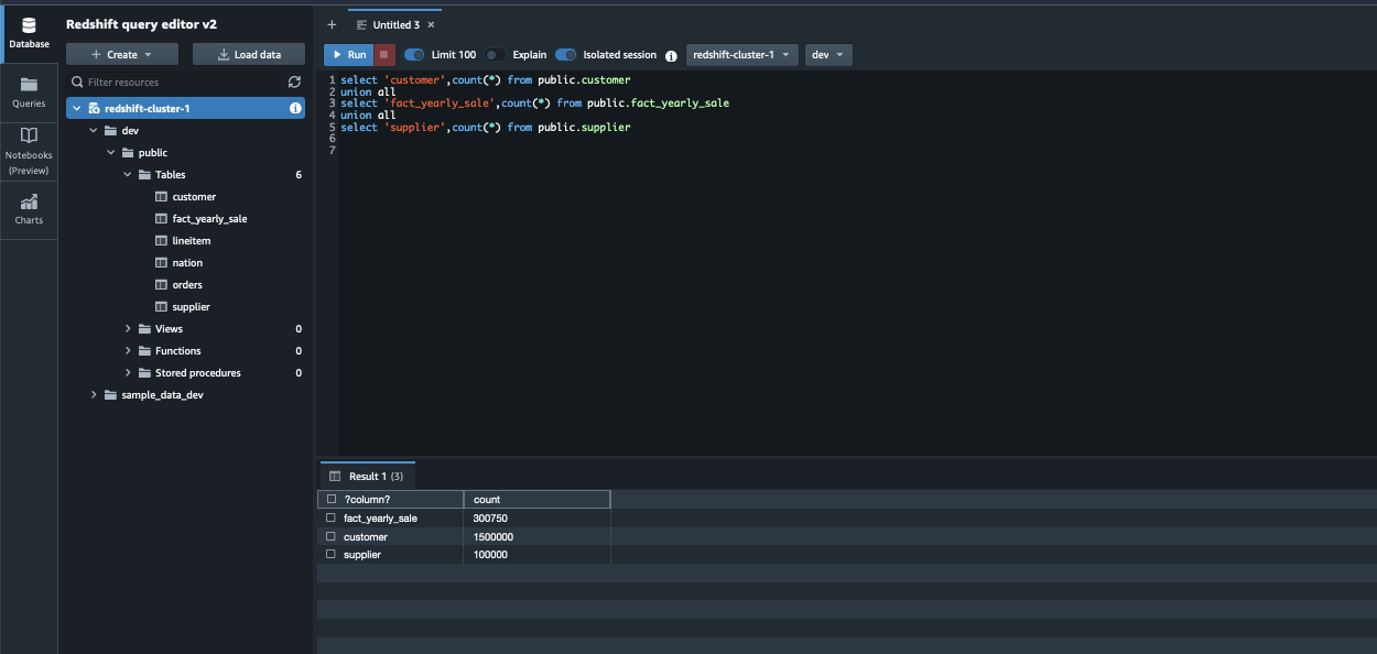
- When you’re connected as a federated user, run the following SQL commands to query the cross_account_glue_schema data lake table.
The following screenshot shows that user Ethan, who is part of the awssso-sales group, has access to two columns and all rows from the Data Catalog.

The following screenshot shows that user Frank, who is part of the awssso-finance group, has access to all columns for records that have star_rating as 5.

The following screenshot shows that user Brian, who is part of awssso-sales and awssso-finance, has access to all columns for records that have star_rating as 5 and access to only two columns (other columns are returned NULL) for records with star_rating other than 5.

Subscribe to QuickSight with IAM Identity Center
In this post, we set up QuickSight in the same account where the Redshift cluster exists. You can use the same or a different member account for QuickSight setup. To subscribe to QuickSight, complete the following steps:
- Sign in to your AWS account and open the QuickSight console.
- Choose Sign up for QuickSight.

- Enter a notification email address for the QuickSight account owner or group. This email address will receive service and usage notifications.
- Select the identity option that you want to subscribe with. For this post, we select Use AWS IAM Identity Center.
- Enter a QuickSight account name.
- Choose Configure.

- Next, assign groups in IAM Identity Center to roles in QuickSight (admin, author, and reader.) This step enables your users to access the QuickSight application. In this post, we choose awssso-sales and awssso-finance for Admin group.
- Specify an IAM role to control QuickSight access to your AWS resources. In this post, we select Use QuickSight managed role (default).
- For this post, we deselect Add Paginated Reports.
- Review the choices that you made, then choose Finish.

Enable trusted identity propagation in QuickSight
Trusted identity propagation authenticates the end-user in Amazon Redshift when they access QuickSight assets that use a trusted identity propagation enabled data source. When an author creates a data source with trusted identity propagation, the identity of the data source consumers in QuickSight is propagated and logged in AWS CloudTrail. This allows database administrators to centrally manage data security in Amazon Redshift and automatically apply data security rules to data consumers in QuickSight.
To configure QuickSight to connect to Amazon Redshift data sources with trusted identity propagation, configure Amazon Redshift OAuth scopes to your QuickSight account:
For example:
After you have added the scope, the following command lists all OAuth scopes that are currently on a QuickSight account:
The following code is the example with output:
For more information, refer to Authorizing connections from Amazon QuickSight to Amazon Redshift clusters.
For QuickSight to connect to a Redshift instance, you must add an appropriate IP address range in the Redshift security group for the specific AWS Region. For more information, see AWS Regions, websites, IP address ranges, and endpoints.
Test your IAM Identity Center and Amazon Redshift integration with QuickSight
Now you’re ready to connect to Amazon Redshift using QuickSight.
- In the management account, open the IAM Identity Center console and copy the AWS access portal URL from the dashboard.
- Sign out from the management account and enter the AWS access portal URL in a new browser window.
- In the pop-up window, enter your IdP credentials.
- After successful authentication, you’ll be logged in to the AWS Management Console as a federated user.
- On the Applications tab, select the QuickSight app.
- After you federate to QuickSight, choose Datasets.
- Select New Dataset and then choose Redshift (Auto Discovered).
- Enter your data source details. Make sure to select Single sign-on for Authentication method.
- Choose Create data source.

Congratulations! You’re signed in using IAM Identity Center integration with Amazon Redshift and are ready to explore and analyze your data using QuickSight.
The following screenshot from QuickSight shows that user Ethan, who is part of the awssso-sales group, has access to two columns and all rows from the Data Catalog.

The following screenshot from QuickSight shows that user Frank, who is part of the awssso-finance group, has access to all columns for records that have star_rating as 5.

The following screenshot from QuickSight shows that user Brian, who is part of awssso-sales and awssso-finance, has access to all columns for records that have star_rating as 5 and access to only two columns (other columns are returned NULL) for records with star_rating other than 5.

Clean up
Complete the following steps to clean up your resources:
- Delete the data from the S3 bucket.
- Delete the Data Catalog objects that you created as part of this post.
- Delete the Lake Formation resources and QuickSight account.
- If you created new Redshift cluster for testing this solution, delete the cluster.
Conclusion
In this post, we established cross-account access to enable centralized user authentication through IAM Identity Center in the management account, while keeping the Amazon Redshift and AWS Glue resources isolated by business unit in separate member accounts. We used Query Editor V2 for querying the data from Amazon Redshift. Then we showed how to build user-facing dashboards by integrating with QuickSight. Refer to Integrate Tableau and Okta with Amazon Redshift using AWS IAM Identity Center to learn about integrating Tableau and Okta with Amazon Redshift using IAM Identity Center.
Learn more about IAM Identity Center with Amazon Redshift, QuickSight, and Lake Formation. Leave your questions and feedback in the comments section.
About the Authors
 Srividya Parthasarathy is a Senior Big Data Architect on the AWS Lake Formation team. She enjoys building data mesh solutions and sharing them with the community.
 Maneesh Sharma is a Senior Database Engineer at AWS with more than a decade of experience designing and implementing large-scale data warehouse and analytics solutions. He collaborates with various Amazon Redshift Partners and customers to drive better integration.
 Poulomi Dasgupta is a Senior Analytics Solutions Architect with AWS. She is passionate about helping customers build cloud-based analytics solutions to solve their business problems. Outside of work, she likes travelling and spending time with her family.


 Poulomi Dasgupta is a Senior Analytics Solutions Architect with AWS. She is passionate about helping customers build cloud-based analytics solutions to solve their business problems. Outside of work, she likes travelling and spending time with her family.
 Adekunle Adedotun is a Sr. Database Engineer with Amazon Redshift service. He has been working on MPP databases for 6 years with a focus on performance tuning. He also provides guidance to the development team for new and existing service features.


 Matt Nispel is an Enterprise Solutions Architect at AWS. He has more than 10 years of experience building cloud architectures for large enterprise companies. At AWS, Matt helps customers rearchitect their applications to take full advantage of the cloud. Matt lives in Minneapolis, Minnesota, and in his free time enjoys spending time with friends and family.
 Dan Dressel is a Senior Analytics Specialist Solutions Architect at AWS. He is passionate about databases, analytics, machine learning, and architecting solutions. In his spare time, he enjoys spending time with family, nature walking, and playing foosball.