All posts by Sam Mokhtari

Optimize your modern data architecture for sustainability: Part 2 – unified data governance, data movement, and purpose-built analytics

Post Syndicated from Sam Mokhtari original https://aws.amazon.com/blogs/architecture/optimize-your-modern-data-architecture-for-sustainability-part-2-unified-data-governance-data-movement-and-purpose-built-analytics/

In the first part of this blog series, Optimize your modern data architecture for sustainability: Part 1 – data ingestion and data lake, we focused on the 1) data ingestion, and 2) data lake pillars of the modern data architecture. In this blog post, we will provide guidance and best practices to optimize the components within the 3) unified data governance, 4) data movement, and 5) purpose-built analytics pillars.
Figure 1 shows the different pillars of the modern data architecture. It includes data ingestion, data lake, unified data governance, data movement, and purpose-built analytics pillars.

Modern Data Analytics Reference Architecture on AWS

Figure 1. Modern Data Analytics Reference Architecture on AWS

3. Unified data governance

A centralized Data Catalog is responsible for storing business and technical metadata about datasets in the storage layer. Administrators apply permissions in this layer and track events for security audits.

Data discovery

To increase data sharing and reduce data movement and duplication, enable data discovery and well-defined access controls for different user personas. This reduces redundant data processing activities. Separate teams within an organization can rely on this central catalog. It provides first-party data (such as sales data) or third-party data (such as stock prices, climate change datasets). You’ll only need access data once, rather than having to pull from source repeatedly.

AWS Glue Data Catalog can simplify the process for adding and searching metadata. Use AWS Glue crawlers to update the existing schemas and discover new datasets. Carefully plan schedules to reduce unnecessary crawling.

Data sharing

Establish well-defined access control mechanisms for different data consumers using services such as AWS Lake Formation. This will enable datasets to be shared between organizational units with fine-grained access control, which reduces redundant copying and movement. Use Amazon Redshift data sharing to avoid copying the data across data warehouses.

Well-defined datasets

Create well-defined datasets and associated metadata to avoid unnecessary data wrangling and manipulation. This will reduce resource usage that might result from additional data manipulation.

4. Data movement

AWS Glue provides serverless, pay-per-use data movement capability, without having to stand up and manage servers or clusters. Set up ETL pipelines that can process tens of terabytes of data.

To minimize idle resources without sacrificing performance, use auto scaling for AWS Glue.

You can create and share AWS Glue workflows for similar use cases by using AWS Glue blueprints, rather than creating an AWS Glue workflow for each use case. AWS Glue job bookmark can track previously processed data.

Consider using Glue Flex Jobs for non-urgent or non-time sensitive data integration workloads such as pre-production jobs, testing, and one-time data loads. With Flex, AWS Glue jobs run on spare compute capacity instead of dedicated hardware.

Joins between several dataframes is a common operation in Spark jobs. To reduce shuffling of data between nodes, use broadcast joins when one of the merged dataframes is small enough to be duplicated on all the executing nodes.

The latest AWS Glue version provides more new and efficient features for your workload.

5. Purpose-built analytics

Data Processing modes

Real-time data processing options need continuous computing resources and require more energy consumption. For the most favorable sustainability impact, evaluate trade-offs and choose the optimal batch data processing option.

Identify the batch and interactive workload requirements and design transient clusters in Amazon EMR. Using Spot Instances and configuring instance fleets can maximize utilization.

To improve energy efficiency, Amazon EMR Serverless can help you avoid over- or under-provisioning resources for your data processing jobs. Amazon EMR Serverless automatically determines the resources that the application needs, gathers these resources to process your jobs, and releases the resources when the jobs finish.

Amazon Redshift RA3 nodes can improve compute efficiency. With RA3 nodes, you can scale compute up and down without having to scale storage. You can choose Amazon Redshift Serverless to intelligently scale data warehouse capacity. This will deliver faster performance for the most demanding and unpredictable workloads.

Energy efficient transformation and data model design

Data processing and data modeling best practices can reduce your organization’s environmental impact.

To avoid unnecessary data movement between nodes in an Amazon Redshift cluster, follow best practices for table design.

You can also use automatic table optimization (ATO) for Amazon Redshift to self-tune tables based on usage patterns.

Use the EXPLAIN feature in Amazon Athena or Amazon Redshift to tune and optimize the queries.

The Amazon Redshift Advisor provides specific, tailored recommendations to optimize the data warehouse based on performance statistics and operations data.

Consider migrating Amazon EMR or Amazon OpenSearch Service to a more power-efficient processor such as AWS Graviton. AWS Graviton 3 delivers 2.5–3 times better performance over other CPUs. Graviton 3-based instances use up to 60% less energy for the same performance than comparable EC2 instances.

Minimize idle resources

Use auto scaling features in EMR Clusters or employ Amazon Kinesis Data Streams On-Demand to minimize idle resources without sacrificing performance.

AWS Trusted Advisor can help you identify underutilized Amazon Redshift Clusters. Pause Amazon Redshift clusters when not in use and resume when needed.

Energy efficient consumption patterns

Consider querying the data in place with Amazon Athena or Amazon Redshift Spectrum for one-off analysis, rather than copying the data to Amazon Redshift.

Enable a caching layer for frequent queries as needed. This is in addition to the result caching that comes built-in with services such as Amazon Redshift. Also, use Amazon Athena Query Result Reuse for every query where the source data doesn’t change frequently.

Use materialized views capabilities available in Amazon Redshift or Amazon Aurora Postgres to avoid unnecessary computation.

Use federated queries across data stores powered by Amazon Athena federated query or Amazon Redshift federated query to reduce data movement. For querying across separate Amazon Redshift clusters, consider using Amazon Redshift data sharing feature that decreases data movement between these clusters.

Track and assess improvement for environmental sustainability

The optimal way to evaluate success in optimizing your workloads for sustainability is to use proxy measures and unit of work KPI. This can be GB per transaction for storage, or vCPU minutes per transaction for compute.

In Table 1, we list certain metrics you could collect on analytics services as proxies to measure improvement. These fall under each pillar of the modern data architecture covered in this post.

Pillar Metrics
Unified data governance
Data movement
Purpose-built Analytics

Table 1. Metrics for the Modern data architecture pillars

Conclusion

In this blog post, we provided best practices to optimize processes under the unified data governance, data movement, and purpose-built analytics pillars of modern architecture.

If you want to learn more, check out the Sustainability Pillar of the AWS Well-Architected Framework and other blog posts on architecting for sustainability.

If you are looking for more architecture content, refer to the AWS Architecture Center for reference architecture diagrams, vetted architecture solutions, Well-Architected best practices, patterns, icons, and more.

How to select a Region for your workload based on sustainability goals

Post Syndicated from Sam Mokhtari original https://aws.amazon.com/blogs/architecture/how-to-select-a-region-for-your-workload-based-on-sustainability-goals/

The Amazon Web Services (AWS) Cloud is a constantly expanding network of Regions and points of presence (PoP), with a global network infrastructure linking them together. The choice of Regions for your workload significantly affects your workload KPIs, including performance, cost, and carbon footprint.

The Well-Architected Framework’s sustainability pillar offers design principles and best practices that you can use to meet sustainability goals for your AWS workloads. It recommends choosing Regions for your workload based on both your business requirements and sustainability goals. In this blog, we explain how to select an appropriate AWS Region for your workload. This process includes two key steps:

  • Assess and shortlist potential Regions for your workload based on your business requirements.
  • Choose Regions near Amazon renewable energy projects and Region(s) where the grid has a lower published carbon intensity.

To demonstrate this two-step process, let’s assume we have a web application that must be deployed in the AWS Cloud to support end users in the UK and Sweden. Also, let’s assume there is no local regulation that binds the data residency to a specific location. Let’s select a Region for this workload based on guidance in the sustainability pillar of AWS Well-Architected Framework.

Shortlist potential Regions for your workload

Let’s follow the best practice on Region selection in the sustainability pillar of AWS Well-Architected Framework. The first step is to assess and shortlist potential Regions for your workload based on your business requirements.

In What to Consider when Selecting a Region for your Workloads, there are four key business factors to consider when evaluating and shortlisting each AWS Region for a workload:

  • Latency
  • Cost
  • Services and features
  • Compliance

To shortlist your potential Regions:

  • Confirm that these Regions are compliant, based on your local regulations.
  • Use the AWS Regional Services Lists to check if the Regions have the services and features you need to run your workload.
  • Calculate the cost of the workload on each Region using the AWS Pricing Calculator.
  • Test the network latency between your end user locations and each AWS Region.

At this point, you should have a list of AWS Regions. For this sample workload, let’s assume only Europe (London) and Europe (Stockholm) Regions are shortlisted. They can address the requirements for latency, cost, and features for our use case.

Choose Regions for your workload

After shortlisting the potential Regions, the next step is to choose Regions for your workload. Choose Regions near Amazon renewable energy projects or Regions where the grid has a lower published carbon intensity. To understand this step, you need to first understand the Greenhouse Gas (GHG) Protocol to track emissions.

Based on the GHG Protocol, there are two methods to track emissions from electricity production: market-based and location-based. Companies may choose one of these methods based on their relevant sustainability guidelines to track and compare their year-to-year emissions. Amazon uses the market-based model to report our emissions.

AWS Region(s) selection based on market-based method

With the market-based method, emissions are calculated based on the electricity that businesses have chosen to purchase. For example, the business could decide to contract and purchase electricity produced by renewable energy sources like solar and wind.

Amazon’s goal is to power our operations with 100% renewable energy by 2025 – five years ahead of our original 2030 target. We contract for renewable power from utility-scale wind and solar projects that add clean energy to the grid. These new renewable projects support hundreds of jobs and hundreds of millions of dollars investment in local communities. Find more details about our work around the globe. We support these grids through the purchase of environmental attributes, like Renewable Energy Certificates (RECs) and Guarantees of Origin (GoO), in line with our renewable energy methodology. As a result, we have a number of Regions listed that are powered by more than 95% renewable energy on the Amazon sustainability website.

Choose one of these Regions to help you power your workload with more renewable energy and reduce your carbon footprint. For the sample workload we’re using as our example, both the Europe (London) and Europe (Stockholm) Regions are in this list. They are powered by over 95% renewable energy based on the market-based emission method.

AWS Regions selection based on location-based carbon method 

The location-based method considers the average emissions intensity of the energy grids where consumption takes place. As a result, wherever the organization conducts business, it assesses emissions from the local electricity system. You can use the emissions intensity of the energy grids through a trusted data source to assess Regions for your workload.

Let’s look how we can use Electricity Maps data to select a Region for our sample workload:

1. Go to Electricity Maps (see Figure 1)

2. Search for South Central Sweden zone to get carbon intensity of electricity consumed for Europe (Stockholm) Region (display aggregated data on yearly basis)

Carbon intensity of electricity for South Central Sweden

Figure 1. Carbon intensity of electricity for South Central Sweden

3. Search for Great Britain to get carbon intensity of electricity consumed for Europe (London) Region (display aggregated data on yearly basis)

Carbon intensity of electricity for Great Britain

Figure 2. Carbon intensity of electricity for Great Britain

As you can determine from Figure 2, the Europe (Stockholm) Region has a lower carbon intensity of electricity consumed compared to the Europe (London) Region.

For our sample workload, we have selected the Europe (Stockholm) Region due to latency, cost, features, and compliance. It also provides 95% renewable energy using the market-based method, and low grid carbon intensity with the location-based method.

Conclusion

In this blog, we explained the process for selecting an appropriate AWS Region for your workload based on both business requirements and sustainability goals.

Further reading:

Optimize your modern data architecture for sustainability: Part 1 – data ingestion and data lake

Post Syndicated from Sam Mokhtari original https://aws.amazon.com/blogs/architecture/optimize-your-modern-data-architecture-for-sustainability-part-1-data-ingestion-and-data-lake/

The modern data architecture on AWS focuses on integrating a data lake and purpose-built data services to efficiently build analytics workloads, which provide speed and agility at scale. Using the right service for the right purpose not only provides performance gains, but facilitates the right utilization of resources. Review Modern Data Analytics Reference Architecture on AWS, see Figure 1.

In this series of two blog posts, we will cover guidance from the Sustainability Pillar of the AWS Well-Architected Framework on optimizing your modern data architecture for sustainability. Sustainability in the cloud is an ongoing effort focused primarily on energy reduction and efficiency across all components of a workload. This will achieve the maximum benefit from the resources provisioned and minimize the total resources required.

Modern data architecture includes five pillars or capabilities: 1) data ingestion, 2) data lake, 3) unified data governance, 4) data movement, and 5) purpose-built analytics. In the first part of this blog series, we will focus on the data ingestion and data lake pillars of modern data architecture. We’ll discuss tips and best practices that can help you minimize resources and improve utilization.

Modern Data Analytics Reference Architecture on AWS

Figure 1. Modern Data Analytics Reference Architecture on AWS

1. Data ingestion

The data ingestion process in modern data architecture can be broadly divided into two main categories: batch, and real-time ingestion modes.

To improve the data ingestion process, see the following best practices:

Avoid unnecessary data ingestion

Work backwards from your business needs and establish the right datasets you’ll need. Evaluate if you can avoid ingesting data from source systems by using existing publicly available datasets in AWS Data Exchange or Open Data on AWS. Using these cleaned and curated datasets will help you to avoid duplicating the compute and storage resources needed to ingest this data.

Reduce the size of data before ingestion

When you design your data ingestion pipelines, use strategies such as compression, filtering, and aggregation to reduce the size of ingested data. This will permit smaller data sizes to be transferred over network and stored in the data lake.

To extract and ingest data from data sources such as databases, use change data capture (CDC) or date range strategies instead of full-extract ingestion. Use AWS Database Migration Service (DMS) transformation rules to selectively include and exclude the tables (from schema) and columns (from wide tables, for example) for ingestion.

Consider event-driven serverless data ingestion

Adopt an event-driven serverless architecture for your data ingestion so it only provisions resources when work needs to be done. For example, when you use AWS Glue jobs and AWS Step Functions for data ingestion and pre-processing, you pass the responsibility and work of infrastructure optimization to AWS.

2. Data lake

Amazon Simple Storage Service (S3) is an object storage service which customers use to store any type of data for different use cases as a foundation for a data lake. To optimize data lakes on Amazon S3, follow these best practices:

Understand data characteristics

Understand the characteristics, requirements, and access patterns of your workload data in order to optimally choose the right storage tier. You can classify your data into categories shown in Figure 2, based on their key characteristics.

Data Characteristics

Figure 2. Data Characteristics

Adopt sustainable storage options

Based on your workload data characteristics, use the appropriate storage tier to reduce the environmental impact of your workload, as shown in Figure 3.

Storage tiering on Amazon S3

Figure 3. Storage tiering on Amazon S3

Implement data lifecycle policies aligned with your sustainability goals

Based on your data classification information, you can move data to more energy-efficient storage or safely delete it. Manage the lifecycle of all your data automatically using Amazon S3 Lifecycle policies.

Amazon S3 Storage Lens delivers visibility into storage usage, activity trends, and even makes recommendations for improvements. This information can be used to lower the environmental impact of storing information on S3.

Select efficient file formats and compression algorithms

Use efficient file formats such as Parquet, where a columnar format provides opportunities for flexible compression options and encoding schemes. Parquet also enables more efficient aggregation queries, as you can skip over the non-relevant data. Using an efficient way of storage and accessing data is translated into higher performance with fewer resources.

Compress your data to reduce the storage size. Remember, you will need to trade off compression level (storage saved on disk) against the compute effort required to compress and decompress. Choosing the right compression algorithm can be beneficial as well. For instance, ZStandard (zstd) provides a better compression ratio compared with LZ4 or GZip.

Use data partitioning and bucketing

Partitioning and bucketing divides your data and keeps related data together. This can help reduce the amount of data scanned per query, which means less compute resources needed to service the workload.

Track and assess the improvement for environmental sustainability

The best way for customers to evaluate success in optimizing their workloads for sustainability is to use proxy measures and unit of work KPIs. For storage, this is GB per transaction, and for compute, it would be vCPU minutes per transaction. To use proxy measures to optimize workloads for energy efficiency, read Sustainability Well-Architected Lab on Turning the Cost and Usage Report into Efficiency Reports.

In Table 1, we have listed certain metrics to use as a proxy metric to measure specific improvements. These fall under each pillar of modern data architecture covered in this post. This is not an exhaustive list, you could use numerous other metrics to spot inefficiencies. Remember, just tracking one metric may not explain the impact on sustainability. Use an analytical exercise of combining the metric with data, type of attributes, type of workload, and other characteristics.

Pillar Metrics
Data ingestion
Data lake

Table 1. Metrics for the Modern data architecture pillars

Conclusion

In this post, we have provided guidance and best practices to help reduce the environmental impact of the data ingestion and data lake pillars of modern data architecture.

In the next post, we will cover best practices for sustainability for the unified governance, data movement, and purpose-built analytics and insights pillars.

Further reading:

Integrate AWS Glue Schema Registry with the AWS Glue Data Catalog to enable effective schema enforcement in streaming analytics use cases

Post Syndicated from Sam Mokhtari original https://aws.amazon.com/blogs/big-data/integrate-aws-glue-schema-registry-with-the-aws-glue-data-catalog-to-enable-effective-schema-enforcement-in-streaming-analytics-use-cases/

Metadata is an integral part of data management and governance. The AWS Glue Data Catalog can provide a uniform repository to store and share metadata. The main purpose of the Data Catalog is to provide a central metadata store where disparate systems can store, discover, and use that metadata to query and process the data.

Another important aspect of data governance is serving and managing the relationship between data stores and external clients, which are the producers and consumers of data. As the data evolves, especially in streaming use cases, we need a central framework that provides a contract between producers and consumers to enable schema evolution and improved governance. The AWS Glue Schema Registry provides a centralized framework to help manage and enforce schemas on data streaming applications using convenient integrations with Apache Kafka and Amazon Managed Streaming for Apache Kafka (Amazon MSK), Amazon Kinesis Data Streams, Apache Flink and Amazon Kinesis Data Analytics for Apache Flink, and AWS Lambda.

In this post, we demonstrate how to integrate Schema Registry with the Data Catalog to enable efficient schema enforcement in streaming analytics use cases.

Stream analytics on AWS

There are many different scenarios where customers want to run stream analytics on AWS while managing the schema evolution effectively. To manage the end-to-end stream analytics life cycle, there are many different applications involved for data production, processing, analytics, routing, and consumption. It can be quite hard to manage changes across different applications for stream analytics use cases. Adding/removing a data field across different stream analytics applications can lead to data quality issues or downstream application failures if it is not managed appropriately.

For example, a large grocery store may want to send orders information using Amazon KDS to it’s backend systems. While sending the order information, customer may want to make some data transformations or run analytics on it. The orders may be routed to different targets depending upon the type of orders and it may be integrated with many backend applications which expect order stream data in specific format. But the order details schema can change due to many different reasons such as new business requirements, technical changes, source system upgrades or something else.

The changes are inevitable but customers want a mechanism to manage these changes effectively while running their stream analytics workloads.  To support stream analytics use cases on AWS and enforce schema and governance, customers can make use of AWS Glue Schema Registry along with AWS Stream analytics services.

You can use Amazon Kinesis Data Firehose data transformation to ingest data from Kinesis Data Streams, run a simple data transformation on a batch of records via a Lambda function, and deliver the transformed records to destinations such as Amazon Simple Storage Service (Amazon S3), Amazon Redshift, Amazon OpenSearch Service, Splunk, Datadog, NewRelic, Dynatrace, Sumologic, LogicMonitor, MongoDB, and an HTTP endpoint. The Lambda function transforms the current batch of records with no information or state from previous batches.

Lambda function also has the stream analytics capability for Amazon Kinesis Data Analytics and Amazon DynamoDB. This feature enables data aggregation and state management across multiple function invocations. This capability uses a tumbling window, which is a fixed-size, non-overlapping time interval of up to 15 minutes. When you apply a tumbling window to a stream, records in the stream are grouped by window and sent to the processing Lambda function. The function returns a state value that is passed to the next tumbling window.

Kinesis Data Analytics provides SQL-based stream analytics against streaming data. This service also enables you to use an Apache Flink application to process stream data. Data can be ingested from Kinesis Data Streams and Kinesis Data Firehose while supporting Kinesis Data Firehose (Amazon S3, Amazon Redshift, Amazon OpenSearch Service, and Splunk), Lambda, and Kinesis Data Streams as destinations.

Finally, you can use the AWS Glue streaming extract, transform, and load (ETL) capability as a serverless method to consume data from Kinesis and Apache Kafka or Amazon MSK. The job aggregates, transforms, and enriches the data using Spark streaming, then continuously loads the results into Amazon S3-based data lakes, data warehouses, DynamoDB, JDBC, and more.

Managing stream metadata and schema evolution is becoming more important for stream analytics use cases. To enable these on AWS, the Data Catalog and Schema Registry allow you to centrally control and discover schemas. Before the release of schema referencing in the Data Catalog, you relied on managing schema evolution separately in the Data Catalog and Schema Registry, which usually leads to inconsistencies between these two. With the new release of the Data Catalog and Schema Registry integration, you can now reference schemas stored in the schema registry when creating or updating AWS Glue tables in the Data Catalog. This helps avoid inconsistency between the schema registry and Data Catalog, which results in end-to-end data quality enforcement.

In this post, we walk you through a streaming ETL example in AWS Glue to better showcase how this integration can help. This example includes reading streaming data from Kinesis Data Streams, schema discovery with Schema Registry, using the Data Catalog to store the metadata, and writing out the results to an Amazon S3 as a sink.

Solution overview

The following high-level architecture diagram shows the components to integrate Schema Registry and the Data Catalog to run streaming ETL jobs. In this architecture, Schema Registry helps centrally track and evolve Kinesis Data Streams schemas.

At a high level, we use the Amazon Kinesis Data Generator (KDG) to stream data to a Kinesis data stream, use AWS Glue to run streaming ETL, and use Amazon Athena to query the data.

In the following sections, we walk you through the steps to build this architecture.

Create a Kinesis data stream

To set up a Kinesis data stream, complete the following steps:

  1. On the Kinesis console, choose Data streams.
  2. Choose Create data stream.
  3. Give the stream a name, such as ventilator_gsr_stream.
  4. Complete stream creation.

Configure Kinesis Data Generator to generate sample data

You can use the KDG with the ventilator template available on the GitHub repo to generate sample data. The following diagram shows the template on the KDG console.

Add a new AWS Glue schema registry

To add a new schema registry, complete the following steps:

  1. On the AWS Glue console, under Data catalog in the navigation pane, choose Schema registries.
  2. Choose Add registry.
  3. For Registry name, enter a name (for example, MyDemoSchemaReg).
  4. For Description, enter an optional description for the registry.
  5. Choose Add registry.

Add a schema to the schema registry

To add a new schema, complete the following steps:

  1. On the AWS Glue console, under Schema registries in the navigation pane, choose Schemas.
  2. Choose Add schema.
  3. Provide the schema name (ventilatorstream_schema_gsr) and attach the schema to the schema registry defined in the previous step.
  4. AWS Glue schemas currently support Avro or JSON formats; for this post, select JSON.
  5. Use the default Compatibility mode and provide the necessary tags as per your tagging strategy.

Compatibility modes allow you to control how schemas can or cannot evolve over time. These modes form the contract between applications producing and consuming data. When a new version of a schema is submitted to the registry, the compatibility rule applied to the schema name is used to determine if the new version can be accepted. For more information on different compatibility modes, refer to Schema Versioning and Compatibility.

  1. Enter the following sample JSON:
    {
      "$id": "https://example.com/person.schema.json",
      "$schema": "http://json-schema.org/draft-07/schema#",
      "title": "Ventilator",
      "type": "object",
      "properties": {
        "ventilatorid": {
          "type": "integer",
          "description": "Ventilator ID"
        },
        "eventtime": {
          "type": "string",
          "description": "Time of the event."
        },
        "serialnumber": {
          "description": "Serial number of the device.",
          "type": "string",
          "minimum": 0
        },
        "pressurecontrol": {
          "description": "Pressure control of the device.",
          "type": "integer",
          "minimum": 0
        },
        "o2stats": {
          "description": "O2 status.",
          "type": "integer",
          "minimum": 0
        },
        "minutevolume": {
          "description": "Volume.",
          "type": "integer",
          "minimum": 0
        },
        "manufacturer": {
          "description": "Volume.",
          "type": "string",
          "minimum": 0
        }
      }
    }

  2. Choose Create schema and version.

Create a new Data Catalog table

To add a new table in the Data Catalog, complete the following steps:

  1. On the AWS Glue Console, under Data Catalog in the navigation pane, choose Tables.
  2. Choose Add table.
  3. Select Add tables from existing schema.
  4. Enter the table name and choose the database.
  5. Select the source type as Kinesis and choose a data stream in your own account.
  6. Choose the respective Region and choose the stream ventilator_gsr_stream.
  7. Choose the MyDemoSchemaReg registry created earlier and the schema (ventilatorstream_schema_gsr) with its respective version.

You should be able to preview the schema.

  1. Choose Next and then choose Finish to create your table.

Create the AWS Glue job

To create your AWS Glue job, complete the following steps:

  1. On the AWS Glue Studio console, choose Jobs in the navigation pane.
  2. Select Visual with a source and target.
  3. Under Source, select Amazon Kinesis and under Target, select Amazon S3.
  4. Choose Create.
  5. Choose Data source.
  6. Configure the job properties such as name, AWS Identity and Access Management (IAM) role, type, and AWS version.

For the IAM role, specify a role that is used for authorization to resources used to run the job and access data stores. Because streaming jobs require connecting to sources and sinks, you need to make sure that the IAM role has permissions to read from Kinesis Data Streams and write to Amazon S3.

  1. For This job runs, select A new script authored by you.
  2. Under Advanced properties, keep Job bookmark disabled.
  3. For Log Filtering, select Standard filter and Spark UI.
  4. Under Monitoring options, enable Job metrics and Continuous logging with Standard filter.
  5. Enable the Spark UI and provide the S3 bucket path to store the Spark event logs.
  6. For Job parameters, enter the following key-values:
    • –output_path – The S3 path where the final aggregations are persisted
    • –aws_region – The Region where you run the job
  7. Leave Connections empty and choose Save job and edit script.
  8. Use the following code for the AWS Glue job (update the values for database, table_name, and checkpointLocation):
import sys
import datetime
import boto3
import base64
from pyspark.sql import DataFrame, Row
from pyspark.context import SparkContext
from pyspark.sql.types import *
from pyspark.sql.functions import *
from awsglue.transforms import *
from awsglue.utils import getResolvedOptions
from awsglue.context import GlueContext
from awsglue.job import Job
from awsglue import DynamicFrame

args = getResolvedOptions(sys.argv, \
['JOB_NAME', \
'aws_region', \
'output_path'])

sc = SparkContext()
glueContext = GlueContext(sc)
spark = glueContext.spark_session
job = Job(glueContext)
job.init(args['JOB_NAME'], args)

# S3 sink locations
aws_region = args['aws_region']
output_path = args['output_path']

s3_target = output_path + "ventilator_metrics"
checkpoint_location = output_path + "cp/"
temp_path = output_path + "temp/"


def processBatch(data_frame, batchId):
now = datetime.datetime.now()
year = now.year
month = now.month
day = now.day
hour = now.hour
minute = now.minute
if (data_frame.count() > 0):
dynamic_frame = DynamicFrame.fromDF(data_frame, glueContext, "from_data_frame")
apply_mapping = ApplyMapping.apply(frame = dynamic_frame, mappings = [ \
("ventilatorid", "long", "ventilatorid", "long"), \
("eventtime", "string", "eventtime", "timestamp"), \
("serialnumber", "string", "serialnumber", "string"), \
("pressurecontrol", "long", "pressurecontrol", "long"), \
("o2stats", "long", "o2stats", "long"), \
("minutevolume", "long", "minutevolume", "long"), \
("manufacturer", "string", "manufacturer", "string")],\
transformation_ctx = "apply_mapping")

dynamic_frame.printSchema()

# Write to S3 Sink
s3path = s3_target + "/ingest_year=" + "{:0>4}".format(str(year)) + "/ingest_month=" + "{:0>2}".format(str(month)) + "/ingest_day=" + "{:0>2}".format(str(day)) + "/ingest_hour=" + "{:0>2}".format(str(hour)) + "/"
s3sink = glueContext.write_dynamic_frame.from_options(frame = apply_mapping, connection_type = "s3", connection_options = {"path": s3path}, format = "parquet", transformation_ctx = "s3sink")

# Read from Kinesis Data Stream
sourceData = glueContext.create_data_frame.from_catalog( \
database = "kinesislab", \
table_name = "ventilator_gsr_new", \
transformation_ctx = "datasource0", \
additional_options = {"startingPosition": "TRIM_HORIZON", "inferSchema": "true"})

sourceData.printSchema()

glueContext.forEachBatch(frame = sourceData, batch_function = processBatch, options = {"windowSize": "100 seconds", "checkpointLocation": "s3://<bucket name>/ventilator_gsr/checkpoint/"})
job.commit()

Our AWS Glue job is ready to read the data from the Kinesis data stream and send it to Amazon S3 in Parquet format.

Query the data using Athena

The processed streaming data is written in Parquet format to Amazon S3. Run an AWS Glue crawler on the Amazon S3 location where the streaming data is written; the crawler updates the Data Catalog. You can then run queries using Athena to start driving relevant insights from the data.

Clean up

It’s always a good practice to clean up all the resources created as part of this post to avoid any undue cost. To clean up your resources, delete the AWS Glue database, tables, crawlers, jobs, service role, and S3 buckets.

Additionally, be sure to clean up all other AWS resources that you created using AWS CloudFormation. You can delete these resources on the AWS CloudFormation console by deleting the stack used for the Kinesis Data Generator.

Conclusion

This post demonstrated the importance of centrally managing metadata and schema evolution in stream analytics use cases. It also described how the integration of the Data Catalog and Schema Registry can help you achieve this on AWS. We used a streaming ETL example in AWS Glue to better showcase how this integration can help to enforce end-to-end data quality.

To learn more and get started, you can check out AWS Glue Data Catalog and AWS Glue Schema Registry.


About the Authors

Dr. Sam Mokhtari is a Senior Solutions Architect at AWS. His main area of depth is data and analytics, and he has published more than 30 influential articles in this field. He is also a respected data and analytics advisor, and has led several large-scale implementation projects across different industries, including energy, health, telecom, and transport.

Amar Surjit is a Sr. Solutions Architect based in the UK who has been working in IT for over 20 years designing and implementing global solutions for enterprise customers. He is passionate about streaming technologies and enjoys working with customers globally to design and build streaming architectures and drive value by analyzing their streaming data.

Secure connectivity patterns to access Amazon MSK across AWS Regions

Post Syndicated from Sam Mokhtari original https://aws.amazon.com/blogs/big-data/secure-connectivity-patterns-to-access-amazon-msk-across-aws-regions/

AWS customers often segment their workloads across accounts and Amazon Virtual Private Cloud (Amazon VPC) to streamline access management while being able to expand their footprint. As a result, in some scenarios you, as an AWS customer, need to make an Amazon Managed Streaming for Apache Kafka (Amazon MSK) cluster accessible to Apache Kafka clients not only in the same Amazon VPC as the cluster but also in a remote Amazon VPC. A guest post by Goldman Sachs presented cross-account connectivity patterns to an MSK cluster using AWS PrivateLink. Inspired by the work of Goldman Sachs, this post demonstrates additional connectivity patterns that can support both cross-account and cross-Region connectivity to an MSK cluster. We also developed sample code that supports the automation of the creation of resources for the connectivity pattern based on AWS PrivateLink.

Overview

Amazon MSK makes it easy to run Apache Kafka clusters on AWS. It’s a fully managed streaming service that automatically configures, and maintains Apache Kafka clusters and Apache Zookeeper nodes for you. Amazon MSK lets you focus on building your streaming solutions and supports familiar Apache Kafka ecosystem tools (such as MirrorMaker, Kafka Connect, and Kafka streams) and helps avoid the challenges of managing the Apache Kafka infrastructure and operations.

If you have workloads segmented across several VPCs and AWS accounts, there may be scenarios in which you need to make Amazon MSK cluster accessible to Apache Kafka clients across VPCs.  To provide secure connection between resources across multiple VPCs, AWS provides several networking constructs. Let’s get familiar with these before discussing the different connectivity patterns:

  • Amazon VPC peering is the simplest networking construct that enables bidirectional connectivity between two VPCs. You can use this connection type to enable between VPCs across accounts and AWS Regions to communicate with each other using private IP addresses.
  • AWS Transit Gateway provides a highly available and scalable design for connecting VPCs. Unlike VPC peering that can go cross-Region, AWS Transit Gateway is a regional service, but you can use inter-Region peering between transit gateways to route traffic across Regions.

AWS PrivateLink is an AWS networking service that provides private access to a specific service instead of all resources within a VPC and without traversing the public internet. You can use this service to expose your own application in a VPC to other users or applications in another VPC via an AWS PrivateLink-powered service (referred to as an endpoint service). Other AWS principals can then create a connection from their VPC to your endpoint service using an interface VPC endpoint.

Amazon MSK networking

When you create an MSK cluster, either via the AWS Management Console or AWS Command Line Interface (AWS CLI), it’s deployed into a managed VPC with brokers in private subnets (one per Availability Zone) as shown in the following diagram. Amazon MSK also creates the Apache ZooKeeper nodes in the same private subnets.

The brokers in the cluster are made accessible to clients in the customer VPC through elastic network interfaces (ENIs) that appear in the customer account. The security groups on the ENIs dictate the source and type of ingress and egress traffic allowed on the brokers.

IP addresses from the customer VPC are attached to the ENIs, and all network traffic stays within the AWS network and is not accessible to the internet.

Connections between clients and an MSK cluster are always private.

This blog demonstrates four connectivity patterns to securely access an MSK cluster from a remote VPC. The following table lists these patterns and their key characteristics. Each pattern aligns with the networking constructs discussed earlier.

VPC Peering AWS Transit Gateway AWS PrivateLink with a single NLB


WS PrivateLink multiple NLB


Bandwidth Limited by instance network performance and flow limits. Up to 50 Gbps

10 Gbps per AZ


10 Gbps per AZ


Pricing Data transfer charge (free if data transfer is within AZs) Data transfer charge + hourly charge per attachment Data transfer charge + interface endpoint charge + Network load balancer charge Data transfer charge + interface endpoint charge + Network load balancer charge
Scalability Recommended for smaller number of VPCs No limit on number of VPCs No limit on number of VPCs No limit on number of VPCs

Let’s explore these connectivity options in more detail.

VPC peering

To access an MSK cluster from a remote VPC, the first option is to create a peering connection between the two VPCs.

Let’s say you use Account A to provision an MSK cluster in us-east-1 Region, as shown in the following diagram. Now, you have an Apache Kafka client in the customer VPC in Account B that needs to access this MSK cluster. To enable this connectivity, you just need to create a peering connection between the VPC in Account A and the VPC in Account B. You should also consider implementing fine-grained network access controls with security groups to make sure that only specific resources are accessible between the peered VPCs.

Because VPC peering works across Regions, you can extend this architecture to provide access to Apache Kafka clients in another Region. As shown in the following diagram, to provide access to Kafka clients in the VPC of Account C, you just need to create another peering connection between the VPC in Account C with the VPC in Account A. The same networking principles apply to make sure only specific resources are reachable. In the following diagram, a solid line indicates a direct connection from the Kafka client to MSK cluster, whereas a dotted line indicates a connection flowing via VPC peering.

VPC peering has the following benefits:*

  • Simplest connectivity option.
  • Low latency.
  • No bandwidth limits (it is just limited by instance network performance and flow limits).
  • Lower overall cost compared to other VPC-to-VPC connectivity options.

However, it has some drawbacks:

  • VPC peering doesn’t support transitive peering, which means that only directly peered VPCs can communicate with each other.
  • You can’t use this connectivity pattern when there are overlapping IPv4 or IPv6 CIDR blocks in the VPCs.
  • Managing access can become challenging as the number of peered VPCs grows.

You can use VPC peering when the number of VPCs to be peered is less than 10.

AWS Transit Gateway

AWS Transit Gateway can provide scalable connectivity to MSK clusters. The following diagram demonstrates how to use this service to provide connectivity to MSK cluster. Let’s again consider a VPC in Account A running an MSK cluster, and an Apache Kafka client in a remote VPC in Account B is looking to connect to this MSK cluster. You set up AWS Transit Gateway to connect these VPCs and use route tables on the transit gateway to control the routing.

To extend this architecture to support access from a VPC in another Region, you need to use another transit gateway because this service can’t span Regions. In other words, for the Apache Kafka client in Account C in us-west-2 to connect to the MSK cluster, you need to peer another transit gateway in us-west-2 with the transit gateway in us-east-1 and work with the route tables to manage access to the MSK cluster. If you need to connect another account in us-west-2, you don’t need an additional transit gateway. The Apache Kafka clients in the new account (Account D) simply require a connection to the existing transit gateway in us-west-2 and the appropriate route tables.

The hub and spoke model for AWS Transit Gateway simplifies management at scale because VPCs only need to connect to one transit gateway per Region to gain access to the MSK cluster in the attached VPCs. However, this setup has some drawbacks:

  • Unlike VPC peering in which you only pay for data transfer charges, Transit Gateway has an hourly charge per attachment in addition to the data transfer fee.
  • This connectivity pattern doesn’t support transitive routing.
  • Unlike VPC peering, Transit Gateway is an additional hop between VPCs which may cause more latency.
  • It has higher latency (an additional hop between VPCs) comparing to VPC Peering.
  • The maximum bandwidth (burst) per Availability Zone per VPC connection is 50 Gbps.

You can use AWS Transit Gateway when you need to provide scalable access to the MSK cluster.

AWS PrivateLink

To provide private, unidirectional access from an Apache Kafka client to an MSK cluster across VPCs, you can use AWS PrivateLink. This also eliminates the need to expose the entire VPC or subnet and prevents issues like having to deal with overlapping CIDR blocks between the VPC that hosts the MSK cluster ENIs and the remote Apache Kafka client VPC.

Let’s do a quick recap of the architecture as explained in blog post How Goldman Sachs builds cross-account connectivity to their Amazon MSK clusters with AWS PrivateLink.

Let’s assume Account A has a VPC with three private subnets and an MSK cluster with three broker nodes in a 3-AZ deployment. You have three ENIs, one for each broker node in each subnet representing the broker nodes, and each ENI gets a private IPv4 address from its subnet’s CIDR block, and an MSK broker DNS endpoint. To expose the MSK cluster in Account A to other accounts via AWS PrivateLink, you have to create a VPC endpoint service in Account A. The VPC endpoint service requires the entity, in this case the MSK cluster, to be fronted by a Network Load Balancer (NLB).

You can choose from two patterns using AWS PrivateLink to provide cross-account access to Amazon MSK: with a single NLB or multiple NLBs.

AWS PrivateLink connectivity pattern with a single NLB

The following diagram illustrates access to an MSK cluster via an AWS PrivateLink connectivity pattern with a single NLB.

In this pattern, you have a single dedicated internal NLB in Account A. The NLB has a separate listener for each MSK broker. Because this pattern has a single NLB endpoint, each of the listeners need to listen on unique port. In the preceding diagram, the ports are depicted as 8443, 8444, and 8445. Correspondingly, for each listener, you have a unique target group, each of which has a single registered target: the IP address of an MSK broker ENI. Because the ports are different from the advertised listeners defined in the MSK cluster for each of the broker nodes, the advertised listeners configuration for each of the broker nodes in the cluster should be updated. Additionally, one target group has all the broker ENI IPs as targets and a corresponding listener (on port 9094), which means a request coming to the NLB on port 9094 can be routed to any of the MSK brokers.

In Account B, you need to create a corresponding VPC endpoint for the VPC endpoint service in Account A. Apache Kafka clients in Account B can connect to the MSK cluster in Account B by directing their requests to the VPC endpoint. For Transport Layer Security (TLS) to work, you also need an Amazon Route 53 private hosted zone with the domain name kafka.<region of the amazon msk cluster>.amazonaws.com, with alias resource record sets for each of the broker endpoints pointing to the VPC endpoint in Account B.

In this pattern, for the Apache Kafka clients local to the VPC with the Amazon MSK broker ENIs in Account A to connect to the MSK cluster, you need to set up a Route 53 private hosted zone, similar to Account B, with alias resource record sets for each of the broker endpoints pointing to the NLB endpoint. This is because the ports in the advertised.listener configuration have been changed for the brokers and the default Amazon MSK broker endpoints won’t work.

To extend this connectivity pattern and provide access to Apache Kafka clients in a remote Region, you need to create a peering connection (which can be via VPC peering or AWS Transit Gateway) between the VPC in Account B and the VPC in the remote Region. The same networking principles apply to make sure only specific intended resources are reachable.

AWS PrivateLink connectivity pattern with multiple NLBs

In the second pattern, you don’t share one VPC endpoint service or NLB across multiple MSK brokers. Instead, you have an independent set for each broker. Each NLB has only one listener listening on the same port (9094) for requests to each Amazon MSK broker. Correspondingly, you have a separate VPC endpoint service for each NLB and each broker. Just like in the first pattern, in Account B, you need a Route53 hosted private zone to alias broker DNS endpoints to VPC endpoints—in this case, they’re aliased to their own specific VPC endpoint.

This pattern has the advantage of not having to modify the advertised listeners configuration in the MSK cluster. However, there is an additional cost of deploying more NLBs, one for each broker. Furthermore, in this pattern, Apache Kafka clients that are local to the VPC with the MSK broker ENIs in Account A can connect to the cluster as usual with no additional setup needed. The following diagram illustrates this setup.

To extend this connectivity pattern and provide access to Apache Kafka clients in a remote Region, you need to create a peering connection between the VPC in Account B and the VPC in the remote Region.

You can use the sample code provided on GitHub to set up the AWS PrivateLink connectivity pattern with multiple NLBs for an MSK cluster. The intent of the code is to automate the creation of multiple resources instead of wiring it manually.

These patterns have the following benefits:

  • They are scalable solutions and do not limit the number of consumer VPCs.
  • AWS PrivateLink allows for VPC CIDR ranges to overlap.
  • You don’t need path definitions or a route table (access only to the MSK cluster), therefore it’s easier to manage

 The drawbacks are as follows:

  • The VPC endpoint and service must be in the same Region.
  • The VPC endpoints support IPv4 traffic only.
  • The endpoints can’t be transferred from one VPC to another.

You can use either connectivity pattern when you need your solution to scale to a large number of Amazon VPCs that can consume each service. You can also use either pattern when the cluster and client VPCs have overlapping IP addresses and when you want to restrict access to only the MSK cluster instead of the VPC itself. The single NLB pattern adds relevant complexity to the architecture because you need to maintain an additional target group and listener that has all brokers registered as well as keep the advertised.listeners property up to date. You can offset that complexity with the multiple NLB pattern but at an additional cost for the increased number of NLBs.

Conclusion

In this post, we explored different secure connectivity patterns to access an MSK cluster from a remote VPC. We also discussed the advantages, challenges, and limitations of each connectivity pattern. You can use this post as guidance to help you identify an appropriate connectivity pattern to address your requirements for accessing an MSK cluster. You can also use a combination of connectivity patterns to address your use case.

References

To read more about the solutions that inspired this post, see How Goldman Sachs builds cross-account connectivity to their Amazon MSK clusters with AWS PrivateLink and the webinar Cross-Account Connectivity Options for Amazon MSK.


About the Authors

Dr. Sam Mokhtari is a Senior Solutions Architect in AWS. His main area of depth is data and analytics, and he has published more than 30 influential articles in this field. He is also a respected data and analytics advisor who led several large-scale implementation projects across different industries including energy, health, telecom, and transport.


Pooja Chikkala is a Solutions Architect in AWS. Big data and analytics is her area of interest. She has 13 years of experience leading large-scale engineering projects with expertise in designing and managing both on-premises and cloud-based infrastructures.


Rajeev Chakrabarti is a Principal Developer Advocate with the Amazon MSK team. He has worked for many years in the big data and data streaming space. Before joining the Amazon MSK team, he was a Streaming Specialist SA helping customers build streaming pipelines.


Imtiaz (Taz) Sayed is the WW Tech Leader for Analytics at AWS. He enjoys engaging with the community on all things data and analytics, and can be reached at IN.


Get started with Flink SQL APIs in Amazon Kinesis Data Analytics Studio

Post Syndicated from Sam Mokhtari original https://aws.amazon.com/blogs/big-data/get-started-with-flink-sql-apis-in-amazon-kinesis-data-analytics-studio/

Before the release of Amazon Kinesis Data Analytics Studio, customers relied on Amazon Kinesis Data Analytics for SQL on Amazon Kinesis Data Streams. With the release of Kinesis Data Analytics Studio, data engineers and analysts can use an Apache Zeppelin notebook within Studio to query streaming data interactively from a variety of sources, like Kinesis Data Streams, Amazon Managed Streaming for Apache Kafka (Amazon MSK), Amazon Simple Storage Service (Amazon S3), and other sources using custom connectors.

In this post, we cover some of the most common query patterns to run on streaming data using Apache Flink relational APIs. Out of the two relational API types supported by Apache Flink, SQL and Table APIs, our focus is on SQL APIs. We expect readers to have knowledge of Kinesis Data Streams, AWS Glue, and AWS Identity and Access Management (IAM). In this post, we use a sales transaction use case to walk you through the examples of tumbling, sliding, session and windows, group by, and joins query operations. We expect readers to have a basic knowledge of SQL queries and streaming window concepts.

Solution architecture

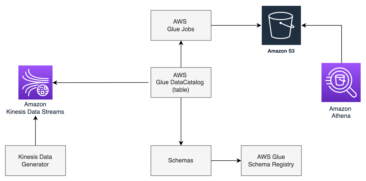
To show the working solution of interactive analytics on streaming data, we use a Kinesis Data Generator UI application to generate the stream of data, which continuously writes to Kinesis Data Streams. For the interactive analytics on Kinesis Data Streams, we use Kinesis Data Analytics Studio that uses Apache Flink as the processing engine, and notebooks powered by Apache Zeppelin. These notebooks come with preconfigured Apache Flink, which allows you to query data from Kinesis Data Streams interactively using SQL APIs. To use SQL queries in the Apache Zeppelin notebook, we configure an AWS Glue Data Catalog table, which is configured to use Kinesis Data Streams as a source. This configuration allows you to query the data stream by referring to the AWS Glue table in SQL queries.

We use an AWS CloudFormation template to create the AWS resources shown in the following diagram.

Set up the environment

After you sign in to your AWS account, launch the CloudFormation template by choosing Launch Stack:


The CloudFormation template configures the following resources in your account:

  • Two Kinesis data streams, one for sales transactions and one for card data
  • A Kinesis Data Analytics Studio application
  • An IAM role (service execution role) for Kinesis Data Analytics Studio
  • Two AWS Glue Data Catalog tables: sales and card

After you complete the setup, sign in to the Kinesis Data Analytics console. On the Kinesis Data Analytics applications page, choose the Studio tab, where you can see the Studio notebook in ready status. Select the Studio notebook, choose Run, and wait until the notebook is in running status. It can take a couple of minutes for the notebook to get into running status.

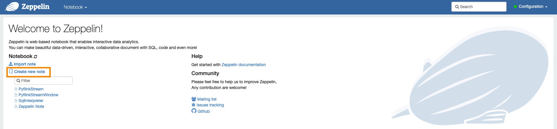
To run the analysis on streaming data, select the Apache Zeppelin notebook environment and open it. You have the option to create a new note in the notebook.

Run stream analytics in an interactive application

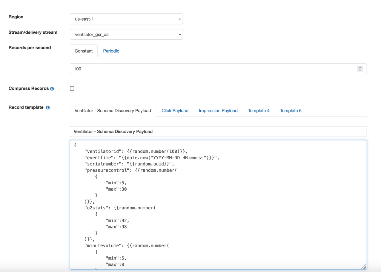
Before you start running interactive analytics with a Studio notebook, you need to start streaming data into your Kinesis data stream, which you created earlier using the CloudFormation stack. To generate streaming data into the data stream, we use a hosted Kinesis Data Generator UI application.

  1. Create an Amazon Cognito user pool in your account and user in that pool. For instructions, see the GitHub repo.
  2. Log in to the Kinesis Data Generator application.
  3. Choose the Region where the CloudFormation template was run to create the Kinesis data stream.
  4. Choose the data stream from the drop-down menu and select the data stream for sales.
  5. Set records per second to 10.
  6. Use the following code for the record template:
{
    "customer_card_id": {{random.number({
            "min":1,
            "max":99
        })}},
    "customer_id": {{random.number({
            "min":100,
            "max":110
        })}},
    "price": {{random.number(
        {
            "min":10,
            "max":500
        }
    )}},
    "product_id": "{{random.arrayElement(
        ["4E5750DC2A1D","E6DA5387367B","B552B4B940D0"]
    )}}"
}
  1. Choose Send Data.

To run the table join queries in the example section, you need to stream sample card data to a separate data stream.

  1. Choose the Region where you created the data stream.
  2. Choose the data stream from the drop-down menu.
  3. Select the data stream for card.
  4. Set records per second to 5.
  5. Use the following code for the record template:
{
    "card_id": {{random.number({
            "min":75,
            "max":99
        })}},
    "card_number": {{random.number({
            "min":23274397,
            "max":47547920
        })}},
    "card_zip": "{{random.arrayElement(
        ["07422","23738","03863"]
    )}}",
    "card_name": "{{random.arrayElement(
        ["Laura Perez","Peter Han","Karla Johnson"]
    )}}"
}
  1. Choose Send Data.
  2. Go back to the notebook note and specify the language Studio uses to run the application.

You need to specify Flink interpreter supported by Apache Zeppelin notebook, like Python, IPython, stream SQL, or batch SQL. Because we use Python Flink streaming SQL APIs in this post, we use the stream SQL interpreter ssql as the first statement:

%flink.ssql(type=update)

Common query patterns with Flink SQL

In this section, we walk you through examples of common query patterns using Flink SQL APIs. In all the examples, we refer to the sales table, which is the AWS Glue table created by the CloudFormation template that has Kinesis Data Streams as a source. It’s the same data stream where you publish the sales data using the Kinesis Data Generator application.

Windows and aggregation

In this section, we cover examples of windowed and aggregate queries: tumbling, sliding, and session window operations.

Tumbling window

In the following example, we use SUM aggregation on a tumbling window. The query emits the total spend for every customer every 30-second window interval.

The following table shows our input data.

proctime customer_id customer_card_id product_id price
2021-04-20 21:31:01.10 75 101 4E5750DC2A1D 110
2021-04-20 21:31:01.115 78 118 B552B4B940D0 80
2021-04-20 21:31:01.328 75 101 E6DA5387367B 60
2021-04-20 21:31:01.504 78 101 4E5750DC2A1D 110
2021-04-20 21:31:01.678 75 148 4E5750DC2A1D 110
2021-04-20 21:31:01.960 78 118 B552B4B940D0 80

We use the following code for our query:

%flink.ssql(type=update)
SELECT TUMBLE_END(proctime, INTERVAL '30' SECOND) as window_end_time, customer_id
, SUM(price) as tumbling_30_seconds_sum
FROM sales
GROUP BY TUMBLE(proctime, INTERVAL '30' SECOND), customer_id

The following table shows our results.

windown_end_time customer_id tumbling_30_seconds_sum
2021-04-20 21:31:01.0 75 170
2021-04-20 21:31:01.0 78 80
2021-04-20 21:31:30.0 75 110
2021-04-20 21:31:30.0 78 190

Sliding window

In this sliding window example, we run a SUM aggregate query that emits the total spend for every customer every 10 seconds for the 30-second window.

The following table shows our input data.

proctime customer_id customer_card_id product_id price
2021-04-20 21:31:01.10 75 101 4E5750DC2A1D 110
2021-04-20 21:31:01.20 78 118 B552B4B940D0 80
2021-04-20 21:31:01.28 75 101 E6DA5387367B 60
2021-04-20 21:31:01.30 78 101 4E5750DC2A1D 110
2021-04-20 21:31:01.36 75 148 4E5750DC2A1D 110
2021-04-20 21:31:01.40 78 118 B552B4B940D0 80

We use the following code for our query:

%flink.ssql(type=update)
SELECT HOP_END(proctime, INTERVAL '10' SECOND, INTERVAL '30' SECOND) AS window_end_time
, customer_id, SUM(price) AS sliding_30_seconds_sum
FROM sales
GROUP BY HOP(proctime, INTERVAL '10' SECOND, INTERVAL '30' SECOND), customer_id

The following table shows our results.

window_end_time customer_id sliding_30_seconds_sum
2021-04-20 21:31:01.10 75 110
2021-04-20 21:31:01.20 75 110
2021-04-20 21:31:01.20 78 80
2021-04-20 21:31:30.30 75 170
2021-04-20 21:31:30.30 78 190
2021-04-20 21:31:30.40 75 280
2021-04-20 21:31:30.40 78 270

Session window

The following example of a session window query finds the total spend per session for a 1-minute gap of inactivity. To generate the result, we stream the data from the Kinesis Data Generator application and stop streaming for more than a minute to create a 1-minute gap of inactivity.

The following table shows our input data.

proctime customer_id customer_card_id product_id price
2021-04-20 21:31:01.10 75 101 4E5750DC2A1D 110
2021-04-20 21:31:01.20 78 118 B552B4B940D0 80
2021-04-20 21:31:01.28 75 101 E6DA5387367B 60
2021-04-20 21:32:50.30 78 101 4E5750DC2A1D 110
2021-04-20 21:32:50.36 75 148 4E5750DC2A1D 110

We use the following code for our query:

%flink.ssql(type=update)
SELECT customer_id, SESSION_START(proctime, INTERVAL '1' MINUTE) AS session_start_time
, SESSION_PROCTIME(proctime, INTERVAL '1' MINUTE) AS session_end_time, SUM(price) AS total_spend
FROM sales
GROUP BY SESSION(proctime, INTERVAL '1' MINUTE), customer_id

The following table shows our results.

session_start_time session_end_time total_spend
2021-04-20 21:31:01.10 2021-04-20 21:32:01.28 250
2021-04-20 21:32:50.30 2021-04-20 21:32:50.36 220

Data filter and consolidation

To show an example of a filter and union operation, we create two separate datasets using the filter condition and combine them using the UNION operation.

The following table shows our input data.

proctime customer_id customer_card_id product_id price
2021-04-20 21:31:01.10 75 101 4E5750DC2A1D 110
2021-04-20 21:31:01.20 78 118 B552B4B940D0 80
2021-04-20 21:31:01.28 75 101 E6DA5387367B 60
2021-04-20 21:32:50.30 78 101 4E5750DC2A1D 110
2021-04-20 21:32:50.36 75 148 4E5750DC2A1D 110

We use the following code for our query:

%flink.ssql(type=update)
SELECT * FROM (
(SELECT customer_id, product_id, price FROM sales WHERE price > 100 AND  product_id <> '4E5750DC2A1D')
UNION
(SELECT customer_id, product_id, price FROM sales WHERE product_id = '4E5750DC2A1D' AND price > 250)
)

The following table shows our results.

customer_id product_id price
78 4E5750DC2A1D 300
75 B552B4B940D0 170
78 B552B4B940D0 110
75 4E5750DC2A1D 260

Table joins

Flink SQL APIs support different types of join conditions, like inner join, outer join, and interval join. You want to limit the resource utilization from growing indefinitely, and run joins effectively. For that reason, in our example, we use table joins using an interval join. An interval join requires one equi-join predicate and a join condition that bounds the time on both sides. In this example, we join the dataset of two Kinesis Data Streams tables based on the card ID, which is a common field between the two stream datasets. The filter condition in the query is based on a time constraint, which restricts resource utilization from growing.

The following table shows our sales input data.

proctime customer_id customer_card_id product_id price
2021-04-20 21:31:01.10 75 101 4E5750DC2A1D 110
2021-04-20 21:31:01.20 78 118 B552B4B940D0 80
2021-04-20 21:31:01.28 75 101 E6DA5387367B 60
2021-04-20 21:32:50.30 78 101 4E5750DC2A1D 110
2021-04-20 21:32:50.36 75 148 4E5750DC2A1D 110

The following table shows our cards input data.

card_id card_number card_zip card_name
101 23274397 23738 Laura Perez
118 54093472 7422 Karla Johnson
101 23274397 23738 Laura Perez
148 91368810 7422 Peter Han

We use the following code for our query:

%flink.ssql(type=update)
SELECT sales.proctime, customer_card_id, card_zip, product_id, price
FROM card INNER JOIN sales ON card.card_id = sales.customer_card_id
WHERE sales.proctime BETWEEN card.proctime - INTERVAL '5' MINUTE AND card.proctime;

The following table shows our results.

proctime customer_card_id card_zip product_id price
2021-04-20 21:31:01.10 101 23738 4E5750DC2A1D 110
2021-04-20 21:31:01.20 118 7422 B552B4B940D0 80
2021-04-20 21:31:01.28 101 23738 E6DA5387367B 60
2021-04-20 21:32:50.30 101 23738 4E5750DC2A1D 110
2021-04-20 21:32:50.36 148 7422 4E5750DC2A1D 110

 Data partitioning and ranking

To show the example of Top-N records, we use the same input dataset as in the previous join example. In this example, we run a query to find the top sales records by sales price in each zip code. We use the OVER window clause to rank sales in each zip code using a PARTITION BY clause. Next, we order the records in each zip code with an ORDER BY clause on the price field in descending order. The result of this operation is a ranking of each record based on the OVER clause condition. We use the external block of the query to filter the result on ranking so that we get the top sales in each zip code.

We use the following code for our query:

%flink.ssql(type=update)
SELECT card_zip, customer_card_id, product_id, price FROM (
SELECT *,
ROW_NUMBER() OVER (PARTITION BY card_zip ORDER BY price DESC) as row_num
FROM card INNER JOIN sales ON card.card_id = sales.customer_card_id
WHERE sales.proctime BETWEEN card.proctime - INTERVAL '5' MINUTE AND card.proctime
)
WHERE row_num = 1

The following table shows our results.

card_zip customer_card_id product_id price
23738 101 4E5750DC2A1D 110
7422 148 4E5750DC2A1D 110

Data transformation

There are times when you want to transform incoming data. The Flink SQL API has many built-in functions to support a wide range of data transformation requirements, including string functions, date functions, arithmetic functions, and so on. For the complete list, see System (Built-in) Functions.

Extract a portion of a string

In this example, we use the SUBSTR string function to subtract the first four digits and only return the last four digits of the card number.

The following table shows our sales input data.

proctime customer_id customer_card_id product_id price
2021-04-20 21:31:01.10 75 101 4E5750DC2A1D 110
2021-04-20 21:31:01.20 78 118 B552B4B940D0 80
2021-04-20 21:31:01.28 75 101 E6DA5387367B 60
2021-04-20 21:32:50.30 78 101 4E5750DC2A1D 110
2021-04-20 21:32:50.36 75 148 4E5750DC2A1D 110

The following table shows our cards input data.

card_id card_number card_zip card_name
101 23274397 23738 Laura Perez
118 54093472 7422 Karla Johnson
101 23274397 23738 Laura Perez
148 91368810 7422 Peter Han

We use the following code for our query:

%flink.ssql(type=update)
SELECT proctime, SUBSTR(card_number,5) AS partial_card_number,    card_zip, product_id, price
FROM card INNER JOIN sales ON card.card_id = sales.customer_card_id

The following table shows our results.

proctime partial_card_number card_zip product_id price
2021-04-20 21:31:01.10 4397 23738 4E5750DC2A1D 110
2021-04-20 21:31:01.20 3472 7422 B552B4B940D0 80
2021-04-20 21:31:01.28 4397 23738 E6DA5387367B 60
2021-04-20 21:32:50.30 4397 23738 4E5750DC2A1D 110
2021-04-20 21:32:50.36 8810 7422 4E5750DC2A1D 110

Replace a substring

In this example, we use the REGEXP_REPLACE string function to remove all the characters after the space from the card_name field. Assuming that the first name and last name are separated by a space, the query returns the first name only.

The following table shows our cards input data.

card_id card_number card_zip card_name
101 23274397 23738 Laura Perez
118 54093472 7422 Karla Johnson
101 23274397 23738 Laura Perez
148 91368810 7422 Peter Han

We use the following code for our query:

%flink.ssql(type=update)
SELECT card_id, REGEXP_REPLACE(card_name,' .*','') card_name
FROM card

The following table shows our results.

card_id card_name
101 Laura
118 Karla
101 Laura
101 Laura
148 Jason

Split the string field into multiple fields

In this example, we use the SPLIT_INDEX string function to split the card_name field into first_name and last_name, assuming the card_name field is a full name separated by space.

The following table shows our cards input data.

card_id card_number card_zip card_name
101 23274397 23738 Laura Perez
118 54093472 7422 Karla Johnson
101 23274397 23738 Laura Perez
148 91368810 7422 Peter Han

We use the following code for our query:

%flink.ssql(type=update)
SELECT card_id, SPLIT_INDEX(card_name,' ',0) first_name, SPLIT_INDEX(card_name,' ',1) last_name
FROM card

The following table shows our results.

card_id first_name last_name
101 Laura Perez
118 Karla Johnson
101 Laura Perez
101 Laura Perez
148 Peter Han

Transform data using a CASE statement

There are times when you want to transform the result value and apply labels to get insights. For our example, we label the risk level as high, medium, or low for every customer (who is purchasing in the window) based on the number of purchases in the last 5-minute sliding window that emits results every 30 seconds.

The following table shows our input data.

proctime customer_id customer_card_id product_id price
2021-04-20 21:31:30.10 75 101 4E5750DC2A1D 110
2021-04-20 21:31:38.20 78 118 B552B4B940D0 80
2021-04-20 21:31:42.28 75 101 E6DA5387367B 60
2021-04-20 21:31:50.30 78 101 4E5750DC2A1D 110
2021-04-20 21:31:50.36 75 148 4E5750DC2A1D 110

We use the following code for our query:

%flink.ssql(type=update)
SELECT customer_id, CASE
WHEN total_purchases BETWEEN 1 AND 2 THEN 'LOW'
WHEN total_purchases BETWEEN 3 AND 10 THEN 'MEDIUM'
ELSE 'HIGH'
END as risk
FROM (
SELECT HOP_END(proctime, INTERVAL '30' SECOND, INTERVAL '5' MINUTE) AS winend
, customer_id, COUNT(1) AS total_purchases
FROM sales
GROUP BY HOP(proctime, INTERVAL '30' SECOND, INTERVAL '5' MINUTE), customer_id
)

The following table shows our results.

customer_id risk
78 LOW
75 HIGH

DateTime data transformation

The Flink SQL API has a wide range of built-in functions to operate on the date timestamp field, like extracting the day, month, week, hour, minute, day of the month, and so on. There are functions to convert the date timestamp field. In this example, we use the MINUTE and HOUR functions to extract the minute of an hour and the hour from the timestamp field.

The following table shows our sales input data.

proctime customer_id customer_card_id product_id price
2021-04-20 21:31:01.10 75 101 4E5750DC2A1D 110
2021-04-20 21:31:01.20 78 118 B552B4B940D0 80
2021-04-20 21:31:01.28 75 101 E6DA5387367B 60
2021-04-20 21:32:50.30 78 101 4E5750DC2A1D 110
2021-04-20 21:32:50.36 75 148 4E5750DC2A1D 110

We use the following code for our query:

%flink.ssql(type=update)
SELECT HOUR(TIMESTAMP proctime) AS transaction_hour, MINUTE(TIMESTAMP proctime) AS transaction_min,customer_id, product_id, price
FROM sales

The following table shows our results.

transaction_hour transaction_min customer_id product_id price
21 31 75 4E5750DC2A1D 110
21 31 78 B552B4B940D0 80
21 31 75 E6DA5387367B 60
21 32 78 4E5750DC2A1D 110
21 32 75 4E5750DC2A1D 110

Conclusion

In this post, we used sales and card examples to demonstrate different query patterns to get insight from streaming data using Apache Flink SQL APIs. We walked you through examples of Flink SQL queries that you can run within Kinesis Data Analytics Studio. In just a few minutes, you can start running interactive analytics with the examples in this post.

You can quickly start developing a stream processing application using Studio from the supported languages like SQL, Python, and Scala. If you want to generate continuous actionable insights, you can easily build and deploy your code as an Apache Flink application with durable state from the notebook within Studio. For more information, see Deploying as an application with durable state.

For further reading on Flink SQL queries that you can use in Kinesis Data Analytics Studio, visit the official page at Apache Flink 1.11 SQL Queries.


About the Authors

Dr. Sam Mokhtari is a Senior Solutions Architect at AWS. His main area of depth is “Data & Analytics” and he published more than 30 influential articles in this field. He is also a respected data & analytics advisor who led several large-scale implementation projects across different industries including energy, health, telecom and transport.


Mitesh Patel is a Senior Solutions Architect at AWS. He works with customers in SMB to help them develop scalable, secure and cost effective solutions in AWS. He enjoys helping customers in modernizing applications using microservices and implementing serverless analytics platform.

Field Notes: Develop Data Pre-processing Scripts Using Amazon SageMaker Studio and an AWS Glue Development Endpoint

Post Syndicated from Sam Mokhtari original https://aws.amazon.com/blogs/architecture/field-notes-develop-data-pre-processing-scripts-using-amazon-sagemaker-studio-and-an-aws-glue-development-endpoint/

This post was co-written with Marcus Rosen, a Principal  – Machine Learning Operations with Rio Tinto, a global mining company. 

Data pre-processing is an important step in setting up Machine Learning (ML) projects for success. Many AWS customers use Apache Spark on AWS Glue or Amazon EMR to run data pre-processing scripts while using Amazon SageMaker to build ML models.  To develop spark scripts in AWS Glue, you can create an environment called a Glue Development (Dev) Endpoint that lets you author and test your data pre-processing scripts iteratively. When you’re satisfied with the results of your development, you can create a Glue ETL job that runs the final script as part of your automation framework.

With the introduction of Amazon SageMaker Studio in AWS re:Invent 2020, you can now use a single web-based IDE to spin up a notebook and perform all ML development steps. These include data pre-processing, ML model training, ML model deployment and monitoring.

This post walks you through how to connect a SageMaker Studio notebook to an AWS Glue Dev Endpoint, so you can use a single tool to iteratively develop both data pre-processing scripts and ML models.

Solution Overview

The following diagram shows the components that are used in this solution.

  • First, we use an AWS CloudFormation template to set up the required networking components (for example, VPC, subnets).
  • Then, we create an AWS Glue Dev Endpoint and use a security group to allow SageMaker Studio to securely access the endpoint.
  • Finally, we create a studio domain and use a SparkMagic kernel to connect to the AWS Glue Dev Endpoint and run spark scripts.

In the Amazon SageMaker Studio notebook, SparkMagic will call a REST API against a Livy server running on the AWS Glue Dev Endpoint. Apache Livy is a service that enables interaction with a remote Spark cluster over a REST API.


The following diagram shows the components that are used in this solution. We use an AWS CloudFormation template to set up the required ntworking components (for example, VPC, subnets).

Set up the VPC

You can use the following CloudFormation template to set up the environment needed for this solution.

launch stack button

This template deploys the following resources in your account:

  • A new VPC, with both public and private subnet.
  • VPC endpoints for the following resources:
  • Security groups for SageMaker Studio, Glue endpoint and VPC endpoints
  • SageMaker Service IAM role
  • AWS Glue Dev Endpoint IAM role
  • Set up the AWS Glue Dev Endpoint

Set up AWS Glue Dev Endpoint

Review this Developer Guide: Adding a Development Endpoint for instructions to create an AWS Glue Dev Endpoint.

Note: you must use the AWS Glue Dev Endpoint IAM role provisioned by the CloudFormation template.

  • In the Networking section, select Choose a VPC, subnet, and security groups.

Then choose the VPC glue security group, which you provisioned through the CloudFormation template.

The AWS Glue Dev Endpoint needs to be secured with an SSH public key, which should be generated within your local environment. An SSH key pair (public/private) can be generated using the ssh-keygen on Linux or using PuTTYgen on Windows.

Glue Dev Endpoint screenshot

The final review page looks similar to the following screenshot.

Final review page

Once the AWS Glue Dev Endpoint is in Ready status, keep note of its private IP address (Glue -> ETL -> Dev Endpoints). You will use this IP for the Livy port forwarding.

Set up SageMaker Studio

We recommend launching the SageMaker Studio resource by following the instructions in Securing Amazon SageMaker Studio connectivity using a private VPC .

Follow these steps when you provision the SageMaker Studio resources:

  • Select Standard setup with the AWS Identity and Access Management (IAM) authentication method.
  • Attach a SageMaker Service IAM role, created by the CloudFormation template, to SageMaker Studio.
  • Under Network and storage, select the same VPC and private subnet as the AWS Glue endpoint.
  • For the Network Access for Studio option, select VPC Only — SageMaker Studio will use your VPC. Direct internet access is disabled.

Then ensure that the security group with the self-referencing rule is attached. Also, check your other required security groups are attached for SageMaker Studio from the CloudFormation template output.

Connect the SageMaker Studio notebook to the AWS Glue Dev Endpoint

Once you launch the SageMaker Studio and you add the users. Follow these steps to connect the SageMaker Studio notebook to the AWS Glue Dev Endpoint:

  1. Open the Studio and go to the launcher page (by pressing the “+” icon on the top-left of the page.
  2. Under Notebooks and compute resources, select SparkMagic in the dropdown menu and select Notebook.
  3. Then open another launcher page, select SparkMagic in the same dropdown menu and select Image terminal. One thing to note is that the SparkMagic app will take some time to initialize. Proceed once the apps are in Ready status (2-3 minutes).

Notebooks and compute resources screenshot

4. Upload the private key into SparkMagic Image terminal. In other words, copy the private key to “.ssh” directory and update its permissions using “chmod 400”.

Note: the private key is corresponding to the public key used when you create the AWS Glue Dev Endpoint.

5. Now, you need to achieve port forwarding of the Livy service in order for SparkMagic kernel to be able to connect to the AWS Glue Dev Endpoint.  You run the following command in the image terminal:

/usr/bin/ssh -4 -N -o ServerAliveInterval=60 -o ServerAliveCountMax=3 -o StrictHostKeyChecking=no -i /root/.ssh/{PRIVATE_KEY} -L 8998:169.254.76.1:8998 glue@{GLUE_ENDPOINT_PRIVATE_IP_ADDRESS}

The command consists of:

  • {PRIVATE_KEY} is the private key file name that you copied into .ssh directory.
  • {GLUE_ENDPOINT_PRIVATE_IP_ADDRESS} is the private IP address of the AWS Glue Dev Endpoint.
  • “8998” is the Livy port we are using for port forwarding.
  • “169.254.76.1” is the remote IP address defined by AWS Glue, this IP address does not change.

Note: Keep this terminal open and the SSH command running in order to keep the Livy session active.

6. Go to the SparkMagic notebook and restart the kernel, by going to the top menu and selecting Kernel > Restart Kernel.

7. Once the notebook kernel is restarted, the connection between the Studio Notebook and the AWS Glue Dev Endpoint is ready. To test the integration, you can run the following example command to list the tables in the AWS Glue Data Catalog.

spark.sql("show tables").show()

To test the integration, you can run the following command to list the tables in the Glue Data Catalog

Cleaning up

To avoid incurring future charges, delete the resources you created:

Conclusion

Our customers needed a single web-based IDE to spin up a notebook and perform all ML development steps including data pre-processing, ML model training, ML model deployment and monitoring. This blog post demonstrated how you can configure a SageMaker Studio notebook and connect to AWS Glue Dev Endpoint. This provides a framework for you to use  when developing both data preprocessing scripts and ML models.

To learn more about how to develop data pre-processing scripts and ML models in Amazon SageMaker, you can check out the examples in this repository.

Field Notes provides hands-on technical guidance from AWS Solutions Architects, consultants, and technical account managers, based on their experiences in the field solving real-world business problems for customers.