Post Syndicated from Anitha Selvan original https://aws.amazon.com/blogs/architecture/know-before-you-go-aws-reinvent-2025-guide-to-well-architected-and-cloud-optimization-sessions/
Are you ready to maximize your Well-Architected and Cloud Optimization learning and networking time at re:Invent 2025? We have put together this comprehensive guide to help you plan your schedule and make the most of the Well-Architected and cloud optimization sessions available this year. These sessions will deliver the practical guidance your teams need to lead strategic cloud initiatives, design next-generation architectures, optimize costs, or secure AI-powered systems.
Key themes at re:Invent for Well-Architected and Cloud Optimization – You can expect to see the following themes at re:Invent 2025
AI-powered architecture and governance
The sessions in this theme showcase how AWS is integrating AI technologies to transform traditional architectural practices. From using AI services for automated Well-Architected reviews to implementing self-evolving systems with agentic AI, these sessions demonstrate how you can use AI to automate architectural decisions, streamline governance processes, and scale best practices across the enterprise.
Sessions: ARC324-R, ARC317-R, SPS320, ARC302-R (session details are posted in the following section)
Well-Architected Framework evolution and implementation
These sessions highlight how the AWS Well-Architected Framework has evolved beyond its original scope to address modern architectural challenges. Attendees will learn how to implement the framework principles across different domains—from IoT security to backup strategies—while focusing on enterprise-scale governance and compliance.
Sessions: ARC204, SEC337, STG313-R, ARC323-R (session details are posted in the following section)
Cost optimization and FinOps
The cost optimization track focuses on innovative approaches to cloud financial management, with a strong emphasis on AI-powered FinOps solutions. Sessions range from hands-on workshops like the Frugal Architect GameDay to chalk talks on establishing effective cost governance models.
Sessions: ARC318-R, COP309-R, ARC309, DEV318 (session details are posted in the following section)
Session formats to fit your learning style
This year’s catalog features an exciting mix of content across different formats: from breakout, chalk talks, workshops, builder sessions to code talks.
Breakout sessions – Stay in the know
Sit back and enjoy these presentations to stay current with the latest solution enhancements and practical applications. AWS experts and guest speakers will share valuable insights and real-world examples.
From ideas to impact: Architecting with cloud best practices
ARC204 | Breakout session | December 1, 8:30 AM
Discover how foundational frameworks like the AWS Well-Architected Framework, AWS Cloud Adoption Framework, and AWS Cloud Operating Model evolved through customer feedback and real-world learnings from thousands of organizations, transforming from structured guidance into dynamic insights for optimizing cloud environments. Learn practical strategies for applying unified best practices to accelerate cloud transformation while managing large-scale architectural changes and maintaining operational excellence.
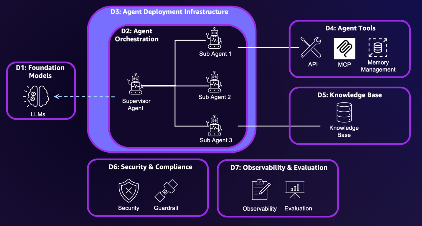
Build a well-architected foundation for scaling generative AI and agentic apps
AIM310 | Breakout session | December 1, 10:00 AM
Move beyond proof-of-concepts to build a production-ready foundation supporting all AI applications across your organization, addressing the critical transition from experimentation to enterprise-scale AI deployment. Navigate model access and management, tool discovery, memory and state handling, and observability at scale while building foundations that seamlessly integrate model access, orchestration workflows, agents, and tools with enterprise-grade governance controls.
AI-Powered Enterprise Architecture with ServiceNow & AWS
ARC337-S | Breakout session | December 2, 3:00 PM
Enterprises face a core challenge: translating architectural vision into resilient cloud reality. See how integrating ServiceNow’s Enterprise Architecture Workspace with the AWS Well-Architected Tool transforms traditional design processes. Through elegant “shift-left” methodologies, architects gain contextual insights that seamlessly blend enterprise modeling with cloud best practices. This presentation is brought to you by ServiceNow, an AWS Partner.
The AI revolution in customer support: Building predictive service systems
SPS315 | Breakout session | December 3, 5:30 PM
Discover how AWS is using generative AI to transform customer support from reactive to proactive. We’ll show how large language models and AI agents are improving customer satisfaction and efficiency. Topics include smart case routing, context-aware support, early problem detection, and responsible AI use. We’ll share real results and discuss balancing AI capabilities with human touch.
Optimize AWS Costs: Developer Tools and Techniques
DEV318 | Breakout session | December 1, 3:00 PM
As cloud applications grow in complexity, optimizing costs becomes crucial for developers. This session explores AWS native tools and coding practices that reduce expenses without compromising performance or scalability.
Chalk talks
AWS speakers set the stage at the beginning of the talk and then open up for discussion. Bring your questions and dive deep into the topic with AWS experts and other customers.
Architecting agentic systems: Self-evolving patterns with AWS AI
ARC324-R | Chalk talk | December 2, 1:30 PM
Learn to architect self-evolving systems using agentic AI that align with AWS Well-Architected principles, exploring cutting-edge patterns for systems that adapt, heal, and optimize themselves autonomously while maintaining architectural integrity. Implement autonomous monitoring and self-healing capabilities with Amazon Bedrock Agents, design AI-driven security controls and automated recovery mechanisms and create systems that continuously adapt to workload patterns while maintaining reliability and performance standards.
Building Well-Architected agentic AI applications
ARC317-R/R1 | Chalk talk | December 2, 3:00 PM and December 4, 1:00 PM
Navigate generative AI agent development with robust architectural practices for security and compliance, focusing on proven patterns for building production-ready agentic AI applications that meet enterprise requirements. Design agent architectures with guardrails, monitoring systems, and access controls using the AWS Well-Architected Generative AI Lens while implementing governance patterns that ensure regulatory compliance and enable systems to scale from prototype to enterprise-wide deployment.
Using generative AI to automate architectural guidance
ARC315 | Chalk talk | December 1, 4:30 PM
Replace time-intensive manual processes with AI-powered systems that generate strategic recommendations, design principles, and best practices at scale while maintaining quality and consistency. Generate organization-specific design principles using AI analysis of architectural patterns, implement AI-driven guidance systems with effective quality control mechanisms, and build knowledge bases that feed AI-powered architectural guidance while maintaining human oversight and addressing ethical considerations.
Agentic architecting: From prototype to production-ready systems
ARC330-R/R1 | Chalk talk | December 2, 5:30PM and December 4, 2:30 PM
Transform prototypes into production-ready systems by incorporating security, monitoring, and CI/CD through agentic architecting, focusing on practical challenges of moving from experimental AI systems to production-grade architectures. Use AI agents to generate and optimize AWS CDK infrastructure and application code, implement automated security improvements and CI/CD pipeline creation, and maintain AWS Well-Architected principles while enabling teams to focus on business logic as AI handles infrastructure complexity.
AI-powered FinOps: Agent-based cloud cost management
ARC318-R/R1 | Chalk talk | December 1, 4:00 PM and December 3, 4:00 PM
Learn how intelligent agents tackle fragmented cost data and optimization processes in complex multi-account environments, moving beyond traditional FinOps approaches to autonomous, intelligent financial optimization. Architect solutions using Amazon OpenSearch Service for data aggregation and Amazon Bedrock for contextual reasoning to design secure, scalable FinOps solutions that continuously optimize costs while delivering measurable business outcomes.
Supercharge your well-architected reviews with AWS Generative AI
SPS320 | Chalk talk | December 3, 4:00 PM
Discover how Koch Industries revolutionized AWS Well-Architected reviews using generative AI, transforming weeks-long manual processes into automated, intelligent systems. Automate architectural assessments using Amazon Bedrock Knowledge Bases and Model Context Protocol (MCP) to scale best practice reviews and optimize workloads in minutes instead of days while achieving more comprehensive, consistent, and actionable recommendations through proven change management and organizational adoption strategies.
Architecting enterprise-scale governance beyond AWS Control Tower
ARC323-R/R1 | Chalk talk | December 3, 11:30 AM and December 4, 2:00PM
Discover advanced governance strategies that build upon AWS Control Tower for enterprise-scale environments requiring sophisticated compliance, security, and operational controls. Implement infrastructure across six Well-Architected Foundations capabilities with critical trade-off understanding, build efficient multi-account structures balancing security requirements with innovation needs, and architect automated compliance checks and policy enforcement at scale while enabling self-service capabilities with centralized governance and security controls.
Securing IoT Workloads with AWS IoT Lens and AWS Security Reference Architecture
SEC337 | Chalk talk | December 3, 11:30 AM
Industrial environments are reaching new levels of connectivity, automation, efficiency, and real-time data insights. However, this increased connectivity also introduces significant security challenges. Unaddressed security concerns can expose vulnerabilities and slow down companies looking to accelerate digital transformation using IoT and cloud. This chalk talk explores relevant techniques, architecture patterns, best practices and AWS security services for securing complex OT/IT environments, IoT devices, edge and cloud using the AWS Well-Architected IoT Lens and AWS Security Reference Architecture (SRA).
Establishing effective cost governance
COP309-R/R1 | Chalk talk | December 3, 3:00 PM and December 4, 12:30 PM
Generative AI agent development demands robust architectural practices for security and compliance. This chalk talk explores proven patterns for architecting secure, efficient AI agents using the AWS Well-Architected Generative AI Lens. Through collaborative discussion and whiteboarding, examine architectural governance and best practices for production environments. Learn to design agent architectures incorporating guardrails, monitoring systems, access controls, and sustainable deployment practices. Gain actionable insights for building secure, efficient, and cost-effective agentic AI applications that scale.
Break down monoliths, modernizing applications on Amazon ECS
CNS346 | Chalk talk | December 2, 4:30 PM
Join this interactive chalk talk to solve a common challenge where monolithic applications take months to deploy new features, and scaling becomes increasingly difficult. We’ll start with a real scenario, an application running on servers with a shared database. Together, we’ll design the modernization path using Amazon ECS and Well-Architected Framework principles. You’ll explore common architecture patterns, containerization strategies, CI/CD automation, and blue/green deployment approaches for ECS. After this session, you’ll walk away with a practical roadmap to transform your monolithic application into scalable microservices. Bring your curiosity and help us build the architecture live.
Hands-on workshop and Builders’ sessions
AWS speakers will introduce the use-case and tools designed to tackle the challenge. You will follow instructions, complete the tasks, and walk away with better understanding of the capabilities.
AI-powered Well-Architected reviews: Building automated governance
ARC302-R | Builders’ session | December 1, 9:00 AM; December 2, 11:30 AM and December 3, 4:00 PM
Build intelligent systems that automate AWS Well-Architected Framework reviews using generative AI, transforming manual architectural assessments into continuous, intelligent governance processes. Evaluate architecture against Well-Architected pillars while incorporating organization-specific requirements, implement continuous analysis of architecture and infrastructure as code templates, and enhance AI understanding of architectural context using Model Context Protocol servers to transform time-intensive reviews into scalable, automated processes with consistent governance.
AI-powered troubleshooting: From chaos to Well-Architected
ARC301-R | Builders’ session | December 1, 8:30 AM; December 2, 3:00 PM and December 3, 10:00 AM
Tackle complex scenarios using AI-powered tools to diagnose and resolve architectural problems, gaining practical experience using AI to transform poorly designed systems into well-architected solutions. Troubleshoot and optimize architectures with scaling bottlenecks and database inefficiencies using Amazon Q, apply Well-Architected principles to enhance performance and security under pressure, and accelerate problem identification and resolution while building AWS optimization expertise and learning to identify architectural anti-patterns before they become critical issues.
The Frugal Architect GameDay: Building cost-aware architectures
ARC309 | Workshop | December 1, 8:00 AM
Compete to implement cost efficiency improvements across multiple AWS services in this interactive GameDay, applying the Laws of the Frugal Architect to real-world scenarios for practical experience in transforming high-cost infrastructure into efficient, sustainable architectures. Address challenges spanning compute, networking, storage, serverless, and observability domains while learning to reduce cloud unit costs and improve profitability without compromising service quality through gamified scenarios that build rapid cost optimization decision-making skills.
Optimize AWS Backup using AI evaluation and Well-Architected best practices
STG313-R | Builders’ session | December 2, 1:30 PM and December 3, 8:30 AM
Enhance AWS Backup implementation using the AWS Backup Evaluator Solution, an AI agent that synthesizes data from multiple sources to provide intelligent backup optimization recommendations. Assess backup environments against the Well-Architected AWS Backup lens using Strands Agents SDK, create unified visibility across backup landscapes to identify optimization opportunities, and implement AI agents that continuously monitor backup efficiency while aligning with AWS best practices to enhance efficiency and cost-effectiveness.
Visit the AWS Cloud Support kiosk in the Venetian
Important notes:
Session dates, times, and locations listed in the post are subject to change as we continue to optimize the schedule on session popularity and venue capacity. Please check this blog post and the re:Invent session catalog regularly for the most up-to-date information about your registered sessions and newly added activities. For a full view of Well-architected content, including sessions with partners, explore the AWS re:Invent catalog and filter on the Well-Architected Framework area of interest.
Remember to reserve your seats early as popular sessions fill up quickly and bring your laptop for hands-on builders’ sessions and workshops. Register today
About the authors


 Dhrubajyoti Mukherjee is a Cloud Infrastructure Architect with a strong focus on data strategy, data governance, and artificial intelligence at Amazon Web Services (AWS). He uses his deep expertise to provide guidance to global enterprise customers across industries, helping them build scalable and secure cloud solutions that drive meaningful business outcomes. Dhrubajyoti is passionate about creating innovative, customer-centric solutions that enable digital transformation, business agility, and performance improvement. Outside of work, Dhrubajyoti enjoys spending quality time with his family and exploring nature through his love of hiking mountains.


 Sean Zou is a Cloud Operations leader with MuleSoft at Salesforce. Sean has been involved in many aspects of MuleSoft’s Cloud Operations, and helped drive MuleSoft’s cloud infrastructure to scale more than tenfold in 7 years. He built the Oversight Engineering function at MuleSoft from scratch.
 Terry Quan focuses on FinOps issues. He works on MuleSoft Engineering on cloud computing budgets and forecasting, cost reduction efforts, costs-to-serve, and coordinates with Salesforce Finance. Terry is a FinOps Practitioner and Professional Certified.
 Audrey Yuan is a Software Engineer with MuleSoft at Salesforce. Audrey works on data lakehouse solutions to help drive cloud maturity across the six pillars of the Well-Architected Framework.
 Rueben Jimenez is a Senior Solutions Architect at AWS, designing and implementing complex data analytics, AI/ML, and cloud infrastructure solutions.
 Avijit Goswami is a Principal Solutions Architect at AWS specialized in data and analytics. He supports AWS strategic customers in building high-performing, secure, and scalable data lake solutions on AWS using AWS managed services and open source solutions. Outside of his work, Avijit likes to travel, hike, watch sports, and listen to music.


