Post Syndicated from Josh DeMuth original https://aws.amazon.com/blogs/devops/a-new-aws-cdk-l2-construct-for-amazon-cloudfront-origin-access-control-oac/
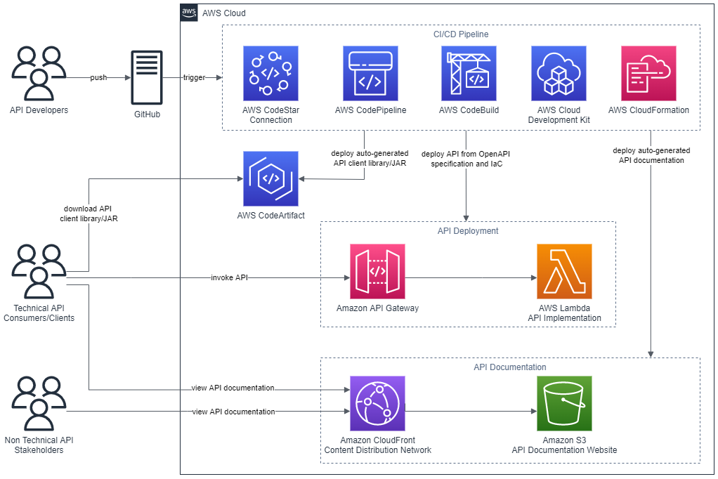
Recently, we launched a new AWS Cloud Development Kit (CDK) L2 construct for Amazon CloudFront Origin Access Control (OAC). This construct simplifies the configuration and maintenance of securing Amazon Simple Storage Service (Amazon S3) CloudFront origins with CDK. Launched in 2022, OAC is the recommended way to secure your CloudFront distributions due to additional security features compared to the legacy Origin Access Identity (OAI). This new construct makes it easier for you to use the latest origin access best practices to build and manage your CloudFront distributions.
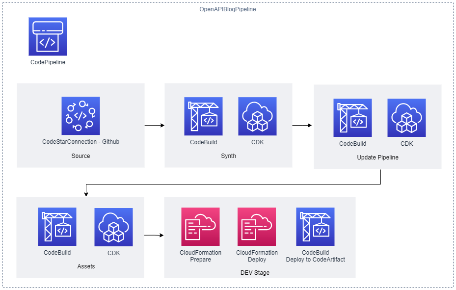
CDK is an open-source software development framework for defining cloud infrastructure in code and provisioning it through AWS CloudFormation. A primary part of CDK is the AWS CDK Construct Library which is a collection of pre-written constructs. Constructs are the basic building blocks of CDK applications. They help reduce the complexity required to define and integrate AWS services together.
There are different levels of constructs, starting with Level 1 (L1) which map directly to a single CloudFormation resource and offer no abstraction. L1 constructs are auto-generated, which means you can build any CloudFormation resource using CDK. The power of the CDK starts with Level 2 (L2) and higher constructs. L2 constructs, also known as curated constructs, are developed by the CDK team and provide a higher-level abstraction through an intuitive intent-based API. You can read more about constructs and their benefits in the CDK user guide.
In this post we’ll explore:
- The reasoning behind the creation of a new L2 construct for OAC
- How to use the new OAC construct
- How to migrate from the legacy OAI construct to the new OAC construct
Background
Amazon CloudFront is a global content delivery network that reduces latency by delivering data to viewers anywhere in the world. CloudFront can connect to different types of locations or origins, such as S3, AWS Lambda function URLs, and custom origins. A full list of supported origins can be found in the CloudFront user guide.
At launch, the new L2 construct supports OAC with S3 origins. Using OAC with S3 allows you to keep your S3 bucket private, yet accessible, through CloudFront. This forces users to access content only through CloudFront where other security features can be applied, like AWS WAF.
There are two ways to restrict buckets to only CloudFront, using OAI (legacy) or OAC (recommended). Both OAI and OAC allow you to secure your buckets, but OAC offers additional benefits, including support for:
- Any new AWS Regions launched after December 2022
- Amazon S3 server-side encryption with AWS Key Management Service (SSE-KMS)
- Dynamic requests (PUT and DELETE) to Amazon S3
- Enhanced security practices like short term credentials, frequent credential rotations, and resource-based policies
Prior to this release, customers had to piece together L1 constructs as well as use escape hatches in order to implement OAC.
The introduction of the new L2 construct simplifies the process by enhancing abstraction and reducing complexity. It makes it easy to use OAC while still offering the flexibility to customize all existing properties available by building with L1’s.
Let’s see the construct in action!
Using the L2
We modified the existing CloudFront Origins L2 to add OAC support. With this change, the S3Origin class has been deprecated in favor of S3BucketOrigin for standard S3 origins, and S3StaticWebsiteOrigin for static website S3 origins.
Using OAC with a standard S3 origin is as simple as passing your bucket as a parameter to the new S3BucketOrigin class using the withOriginAccessControl method.
In the example below, we define a private bucket and let the new L2 construct handle all the OAC configuration for us.
const s3bucket = new s3.Bucket(this, "myBucket", {
    bucketName: `${cdk.Stack.of(this).stackName.toLowerCase()}-oacbucket`,
    blockPublicAccess: s3.BlockPublicAccess.BLOCK_ALL,
    accessControl: s3.BucketAccessControl.PRIVATE,
    enforceSSL: true,
});

const distribution = new cloudfront.Distribution(this, "myDist", {
    defaultBehavior: {
        origin: origins.S3BucketOrigin.withOriginAccessControl(s3bucket),
    }
});
This code defines a S3 bucket configured to block all public access, enforces SSL, and uses private access control. It also defines a CloudFront distribution with the S3 bucket as its origin using the default OAC settings from the OAC construct. By default, the signing behavior is set to “always” and the signing protocol to “sigv4” as is shown below:

Figure 1 – Default OAC Settings for the S3 Origin
In typical CDK fashion, the L2 provides sane defaults out-of-the-box but allows you to customize. Some examples of customizing with the L2, include:
- Changing the signing behavior
- Granting permissions for dynamic requests (write/delete access)
- Migrating to the new construct but continuing to use OAI
S3 Origin with Customer Managed KMS
It is a recommended security best practice to encrypt S3 objects at rest. As detailed in the S3 user guide, using SSE-KMS gives you additional flexibility to meet encryption-related compliance requirements.
If using SSE-KMS, CloudFront must have permission to at least decrypt objects using your AWS KMS key. With the new changes, simply configure your bucket to use an AWS KMS key and the construct will take care of the permissions updates.
The following example shows how to create an SSE-KMS encrypted S3 bucket and use it as a CloudFront origin with OAC:
- Create an AWS KMS Key.
- Create the S3 Bucket with the encryptionKey property set to the AWS KMS key and encryption as KMS.
- Create the CloudFront distribution and use the new S3BucketOrigin class with OAC.
const kmsKey = new kms.Key(this, "myKey");

const myBucket = new s3.Bucket(this, 'myEncryptedBucket', {
  encryption: s3.BucketEncryption.KMS,
  encryptionKey: kmsKey,
  objectOwnership: s3.ObjectOwnership.BUCKET_OWNER_ENFORCED,
});

new cloudfront.Distribution(this, 'myDist', {
  defaultBehavior: {
    origin: origins.S3BucketOrigin.withOriginAccessControl(myBucket)
  },
});
Due to circular dependencies between the bucket, the KMS key, and the CloudFront distribution, when we synthesize the above code, a warning message similar to the following may appear:
To avoid a circular dependency between the KMS key, Bucket, and Distribution during the initial deployment, a wildcard is used in the Key policy condition to match all Distribution IDs.
After the initial deployment, it is recommended to further restrict the policy to adhere to security best practices. Here is an example of how to use an escape hatch to update the policy:
Note: update the existing KMS Key policy to include the statements in scopedDownKeyPolicy
const scopedDownKeyPolicy = {
    Version: "2012-10-17",
    Statement: [
        {
            Effect: "Allow",
            Principal: {
                AWS: `arn:aws:iam::${this.account}:root`,
            },
            Action: "kms:*",
            Resource: "*",
        },
        {
            Effect: "Allow",
            Principal: {
                Service: "cloudfront.amazonaws.com",
            },
            Action: ["kms:Decrypt", "kms:Encrypt", "kms:GenerateDataKey*"],
            Resource: "*",
            Condition: {
                StringEquals: {
                    "AWS:SourceArn": `arn:aws:cloudfront::${this.account}:distribution/<Distribution ID>`//replace <Distribution ID> with the ID of the deployed CloudFront Distribution
                },
            },
        },
    ],
};

const cfnKey = kmsKey.node.defaultChild as kms.CfnKey;
cfnKey.addOverride("Properties.KeyPolicy", scopedDownKeyPolicy);
For detailed instructions on how to update the AWS KMS key policy, please refer to the “Scoping down the key policy” section in the CDK API docs.
Considerations when migrating to the new construct
If you have an existing OAI implementation using the now-deprecated S3Origin class, switching to OAC has potential for application downtime. CloudFront could temporarily lose access to the S3 bucket while the CloudFormation is deploying.
To avoid downtime, it is recommended to perform the upgrade across multiple deployments. This will explicitly give CloudFront permissions to both OAC and OAI in the S3 bucket policy before the migration is performed.
At a high level, the three steps are:
- Deployment 1: update the bucket policy to explicitly allow CloudFront access
- Deployment 2: switch to the new construct
- Deployment 3: optionally remove the code that updated the bucket policy in step 1
For detailed instructions, see the Migrating from OAI to OAC section of the CDK API docs.
Conclusion
In this post, we introduced the new AWS CDK L2 construct for Amazon CloudFront Origin Access Control (OAC), highlighting the advantages of using OAC instead of OAI to secure your Amazon S3 CloudFront origins. We showcased practical implementations of the new construct, focusing on using defaults of the L2 construct along with how to customize for your use case.
To summarize, the new L2 construct and OAC offers these benefits:
- Simplified configuration: the L2 construct simplifies the process of configuring OAC in your CDK application to set up secure access controls between CloudFront and S3 buckets
- Using SSE-KMS encryption: the L2 construct will automatically add the IAM policy statement to the AWS KMS key to allow access to OAC
- Ability to customize: the L2 construct offers properties to override defaults, like changing the signing behavior
- Easily migrate from OAI to OAC: the L2 construct offers options to migrate from OAI to OAC based on your application’s downtime tolerance
At launch, the construct supports an Amazon S3 origin. If there is a particular origin that you are looking to see added to the construct library for OAC, please submit a feature request issue in the aws-cdk GitHub repo. For example, if you are interested in Lambda support for OAC, add your feedback to this feature request.
If you’re new to CDK and want to get started, we highly recommend checking out the CDK documentation and the CDK workshop.