Tag Archives: Monitoring and observability

Monitor AWS workloads without a single line of code with Logz.io and Kinesis Firehose

Post Syndicated from Amos Etzion original https://aws.amazon.com/blogs/big-data/monitor-aws-workloads-without-a-single-line-of-code-with-logz-io-and-kinesis-firehose/

Observability data provides near real-time insights into the health and performance of AWS workloads, so that engineers can quickly address production issues and troubleshoot them before widespread customer impact.

As AWS workloads grow, observability data has been exploding, which requires flexible big data solutions to handle the throughput of large and unpredictable volumes of observability data.

Solution overview

One option is Amazon Kinesis Data Firehose, which is a popular service for streaming huge volumes of AWS data for storage and analytics. By pulling data from Amazon CloudWatch, Amazon Kinesis Data Firehose can deliver data to observability solutions.

Among these observability solutions is Logz.io, which can now ingest metric data from Amazon Kinesis Data Firehose and make it easier to get metrics from your AWS account to your Logz.io account for analysis, alerting, and correlation with logs and traces.

In a few clicks and a few configurations, we’ll see how you can start streaming your metric data (and soon, log data!) to Logz.io for storage and analysis.

Prerequisites

  • Logz.io account – Create a free trial here
  • Logz.io shipping token – Learn about metrics tokens here. You need to be a Logz.io administrator.
  • Access to Amazon CloudWatch and Amazon Kinesis Data Firehose with the appropriate permissions to manage HTTP endpoints.
  • Appropriate permissions to create an Amazon Simple Storage Service (Amazon S3) bucket

Sending Amazon CloudWatch metric data to Logz.io with an Amazon Kinesis Data Firehose

Amazon Kinesis Data Firehose is a service for ingesting, processing, and loading data from large, distributed sources such as logs or clickstreams into multiple consumers for storage and real-time analytics. Kinesis Data Firehose supports more than 50 sources and destinations as of today. This integration can be set up in minutes without a single line of code and enables near real-time analytics for observability data generated by AWS services by using Amazon CloudWatch, Amazon Kinesis Data Firehose, and Logz.io.

Once the integration is configured, Logz.io customers can open the Infrastructure Monitoring product to see their data coming in and populating their dashboards. To see some of the data analytics and correlation you get with Logz.io, check out this short demonstration.

Let’s begin a step-by-step tutorial for setting up the integration.

  • Start by going to Amazon Kinesis Data Firehose and creating a delivery stream with Data Firehose.

Kinesis Firehose Console

  • Next you select a source and destination. Select Direct Put as the source and Logz.io the destination.
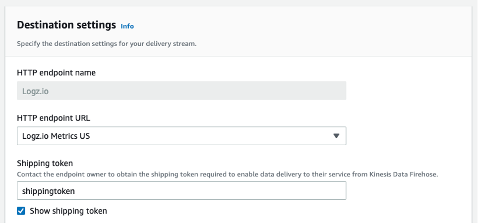
  • Next, configure the destination settings. Give the HTTP endpoint a name, which should include logz.io.
  • Select from the dropdown the appropriate endpoint you would like to use.

If you’re sending data to a European region, then set it to Logz.io Metrics EU. Or you can use the us-east-1 destination by selecting Logz.io Metrics US.

  • Next, add your Logz.io Shipping Token. You can find this by going to Settings in Logz.io and selecting Manage Tokens, which requires Logz.io administrator to access. This ensures that your account is only ingesting data from the defined sources (e.g., this Amazon Kinesis Data Firehose delivery stream).

Kinesis Stream config

Keep Content encoding on Disabled and set your desired Retry Duration.

You can also configure Buffer hints to your preferences.

  • Next, determine your Backup settings in case something goes wrong. In most cases, it’s only necessary to back up the failed data. Simply choose an Amazon S3 bucket or create a new one to store data if it doesn’t make it to Logz.io. Then, select Create a delivery stream.

Now it’s time to connect Amazon CloudWatch to our Amazon Kinesis Data Firehose Delivery Stream.

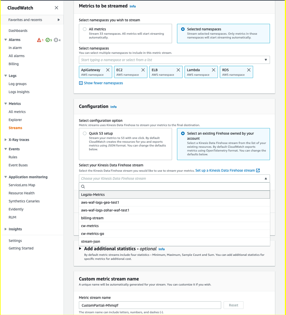
  • Navigate to Amazon CloudWatch and select Streams in the Metrics menu. Select Create metrics stream.
  • Next, you can either select to send all your Amazon CloudWatch metrics to Logz.io, or only metrics from specified namespaces.

In this case, we chose Amazon Elastic Compute Cloud (Amazon EC2), Amazon Relational Database Service (Amazon RDS), AWS Lambda, and Elastic Load Balancing (ELB).

  • Under Configuration, choose the Select an existing Firehose owned by your account option and choose the Amazon Kinesis Data Firehose you just configured.

Metric Streams Config

If you’d like, you can choose additional statistics in the Add additional statistics box, which provides helpful metrics in terms of percentiles to monitor like latency metrics (i.e., which services have the highest average latency). This may increase your costs.

  • Lastly, give your metric stream a name and hit Create metric stream.

That’s it! Without writing a single line of code, we configured an integration with AWS and Logz.io that enables fast and easy infrastructure monitoring through Amazon CloudWatch data collection.

Your metrics will be stored in Logz.io for 18 months out of the box, without requiring any overhead management.

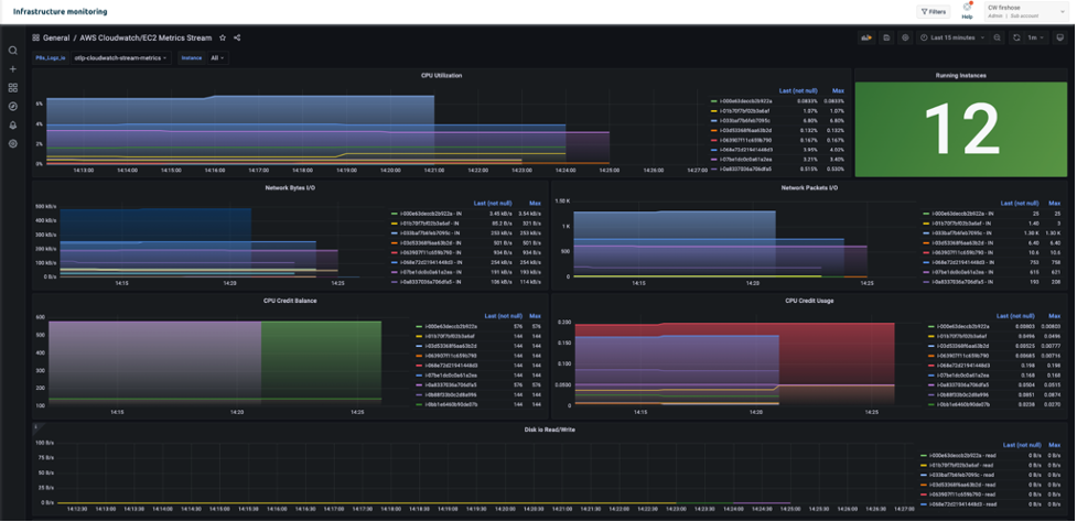
You can also begin to build dashboards and alerts to begin monitoring – like this Amazon EC2 monitoring dashboard below.

ec2 monitoring dashboard Logz.io

Conclusion

This post demonstrated how to configure an integration with AWS and Logz.io for efficient infrastructure monitoring through Amazon CloudWatch.

To learn more about building metrics dashboards in Logz.io, you can watch this video.

Currently, some users might find that they are sending more data than they really need, which can raise costs. In future versions of this integration, it will be easier to narrow down the metrics to reduce costs.

Want to try it yourself? Create a Logz.io account today, navigate to our infrastructure monitoring product, and start streaming metric data to Logz.io to start monitoring.


About the authors

Amos Etzion – Product Manager at Logz.io

Charlie Klein – Product Marketing Manager at Logz.io

Mark Kriaf – Partner Solutions Architect at AWS

New – Amazon CloudWatch Cross-Account Observability

Post Syndicated from Danilo Poccia original https://aws.amazon.com/blogs/aws/new-amazon-cloudwatch-cross-account-observability/

Deploying applications using multiple AWS accounts is a good practice to establish security and billing boundaries between teams and reduce the impact of operational events. When you adopt a multi-account strategy, you have to analyze telemetry data that is scattered across several accounts. To give you the flexibility to monitor all the components of your applications from a centralized view, we are introducing today Amazon CloudWatch cross-account observability, a new capability to search, analyze, and correlate cross-account telemetry data stored in CloudWatch such as metrics, logs, and traces.

You can now set up a central monitoring AWS account and connect your other accounts as sources. Then, you can search, audit, and analyze logs across your applications to drill down into operational issues in a matter of seconds. You can discover and visualize metrics from many accounts in a single place and create alarms that evaluate metrics belonging to other accounts. You can start with an aggregated cross-account view of your application to visually identify the resources exhibiting errors and dive deep into correlated traces, metrics, and logs to find the root cause. This seamless cross-account data access and navigation helps reduce the time and effort required to troubleshoot issues.

Let’s see how this works in practice.

Configuring CloudWatch Cross-Account Observability
To enable cross-account observability, CloudWatch has introduced the concept of monitoring and source accounts:

  • A monitoring account is a central AWS account that can view and interact with observability data shared by other accounts.
  • A source account is an individual AWS account that shares observability data and resources with one or more monitoring accounts.

You can configure multiple monitoring accounts with the level of visibility you need. CloudWatch cross-account observability is also integrated with AWS Organizations. For example, I can have a monitoring account with wide access to all accounts in my organization for central security and operational teams and then configure other monitoring accounts with more restricted visibility across a business unit for individual service owners.

First, I configure the monitoring account. In the CloudWatch console, I choose Settings in the navigation pane. In the Monitoring account configuration section, I choose Configure.

Console screenshot.

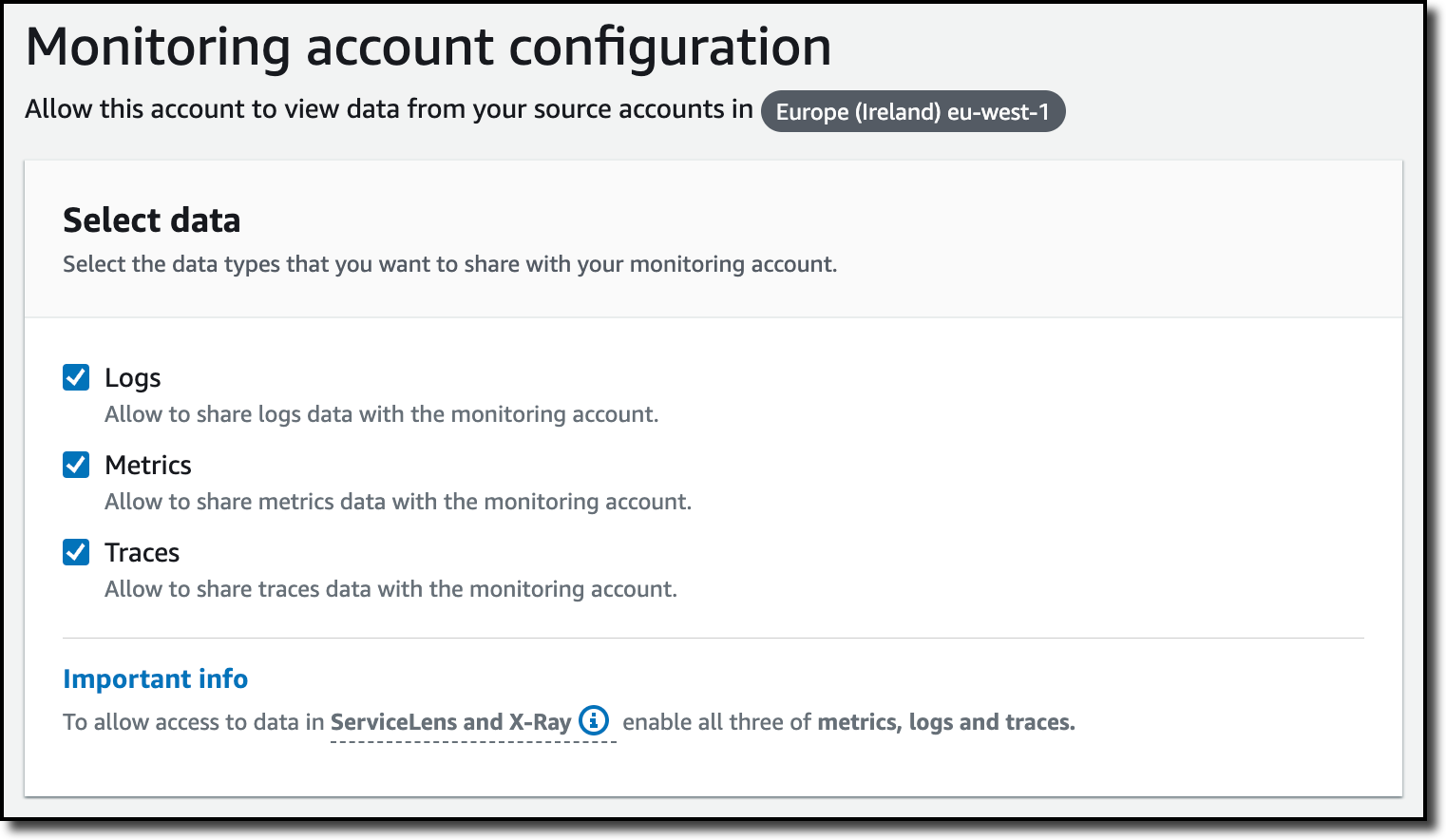
Now I can choose which telemetry data can be shared with the monitoring account: Logs, Metrics, and Traces. I leave all three enabled.

Console screenshot.

To list the source accounts that will share data with this monitoring account, I can use account IDs, organization IDs, or organization paths. I can use an organization ID to include all the accounts in the organization or an organization path to include all the accounts in a department or business unit. In my case, I have only one source account to link, so I enter the account ID.

Console screenshot.

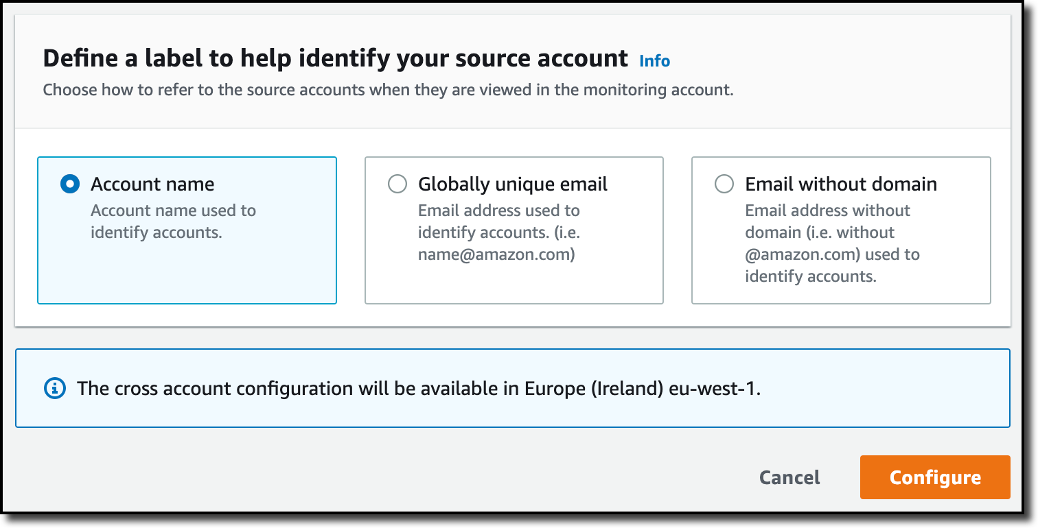
When using the CloudWatch console in the monitoring account to search and display telemetry data, I see the account ID that shared that data. Because account IDs are not easy to remember, I can display a more descriptive “account label.” When configuring the label via the console, I can choose between the account name or the email address used to identify the account. When using an email address, I can also choose whether to include the domain. For example, if all the emails used to identify my accounts are using the same domain, I can use as labels the email addresses without that domain.

There is a quick reminder that cross-account observability only works in the selected Region. If I have resources in multiple Regions, I can configure cross-account observability in each Region. To complete the configuration of the monitoring account, I choose Configure.

Console screenshot.

The monitoring account is now enabled, and I choose Resources to link accounts to determine how to link my source accounts.

Console screenshot.

To link source accounts in an AWS organization, I can download an AWS CloudFormation template to be deployed in a CloudFormation delegated administration account.

To link individual accounts, I can either download a CloudFormation template to be deployed in each account or copy a URL that helps me use the console to set up the accounts. I copy the URL and paste it into another browser where I am signed in as the source account. Then, I can configure which telemetry data to share (logs, metrics, or traces). The Amazon Resource Name (ARN) of the monitoring account configuration is pre-filled because I copy-pasted the URL in the previous step. If I don’t use the URL, I can copy the ARN from the monitoring account and paste it here. I confirm the label used to identify my source account and choose Link.

In the Confirm monitoring account permission dialog, I type Confirm to complete the configuration of the source account.

Using CloudWatch Cross-Account Observability
To see how things work with cross-account observability, I deploy a simple cross-account application using two AWS Lambda functions, one in the source account (multi-account-function-a) and one in the monitoring account (multi-account-function-b). When triggered, the function in the source account publishes an event to an Amazon EventBridge event bus in the monitoring account. There, an EventBridge rule triggers the execution of the function in the monitoring account. This is a simplified setup using only two accounts. You’d probably have your workloads running in multiple source accounts.Architectural diagram.

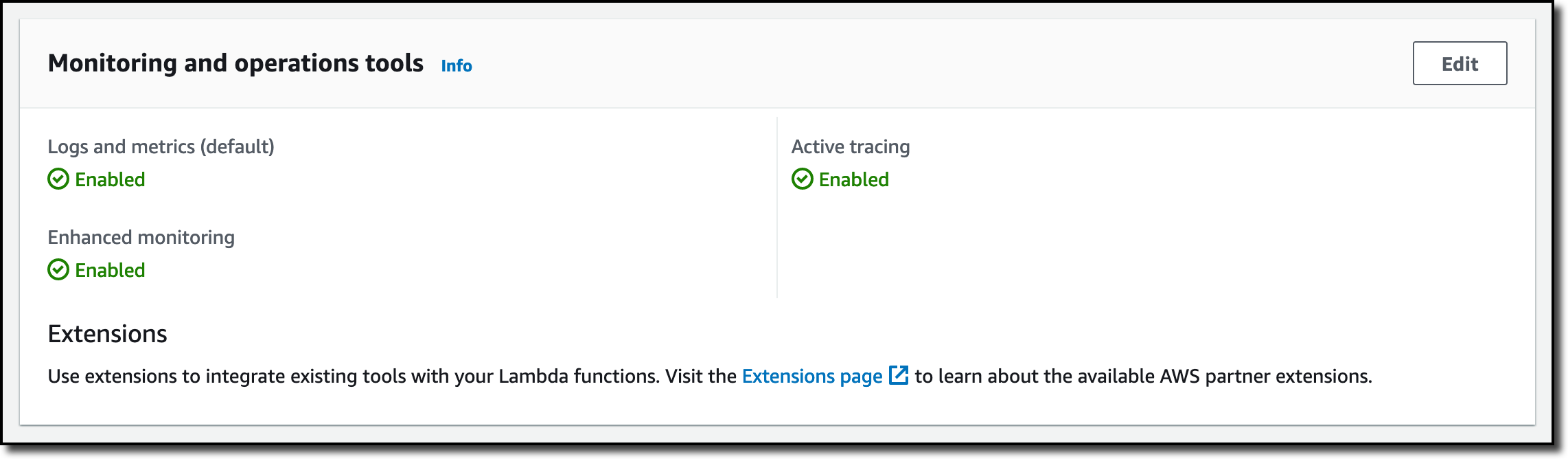
In the Lambda console, the two Lambda functions have Active tracing and Enhanced monitoring enabled. To collect telemetry data, I use the AWS Distro for OpenTelemetry (ADOT) Lambda layer. The Enhanced monitoring option turns on Amazon CloudWatch Lambda Insights to collect and aggregate Lambda function runtime performance metrics.

Console screenshot.

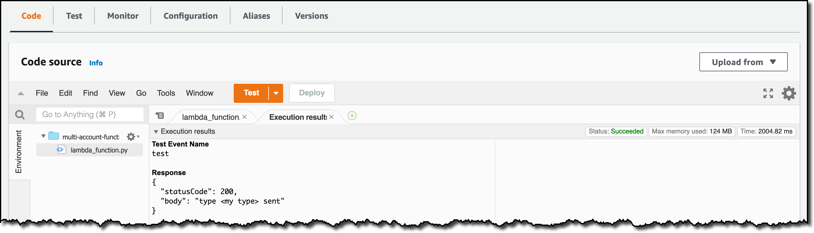
I prepare a test event in the Lambda console of the source account. Then, I choose Test and run the function a few times.

Console screenshot.

Now, I want to understand what the components of my application, running in different accounts, are doing. I start with logs and then move to metrics and traces.

In the CloudWatch console of the monitoring account, I choose Log groups in the Logs section of the navigation pane. There, I search for and find the log groups created by the two Lambda functions running in different AWS accounts. As expected, each log group shows the account ID and label originating the data. I select both log groups and choose View in Logs Insights.

Console screenshot.

I can now search and analyze logs from different AWS accounts using the CloudWatch Logs Insights query syntax. For example, I run a simple query to see the last twenty messages in the two log groups. I include the @log field to see the account ID that the log belongs to.

Console screenshot.

I can now also create Contributor Insights rules on cross-account log groups. This enables me, for example, to have a holistic view of what security events are happening across accounts or identify the most expensive Lambda requests in a serverless application running in multiple accounts.

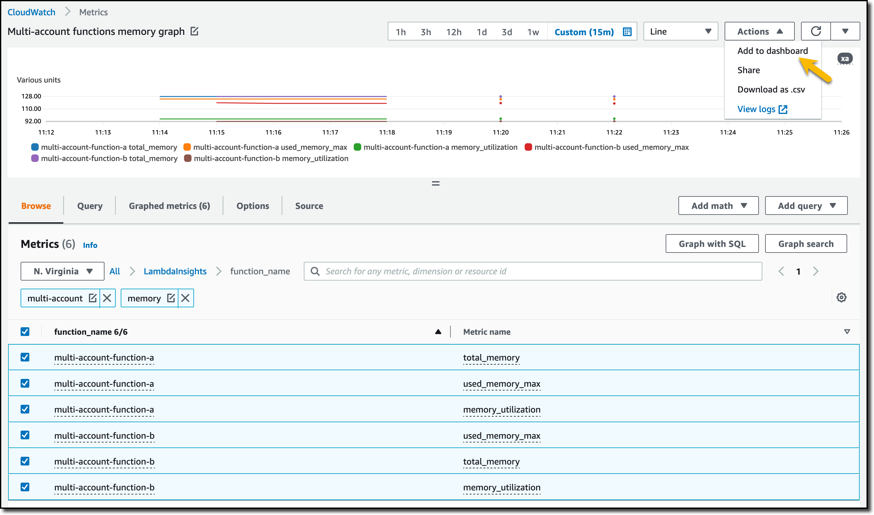
Then, I choose All metrics in the Metrics section of the navigation pane. To see the Lambda function runtime performance metrics collected by CloudWatch Lambda Insights, I choose LambdaInsights and then function_name. There, I search for multi-account and memory to see the memory metrics. Again, I see the account IDs and labels that tell me that these metrics are coming from two different accounts. From here, I can just select the metrics I am interested in and create cross-account dashboards and alarms. With the metrics selected, I choose Add to dashboard in the Actions dropdown.

Console screenshot.

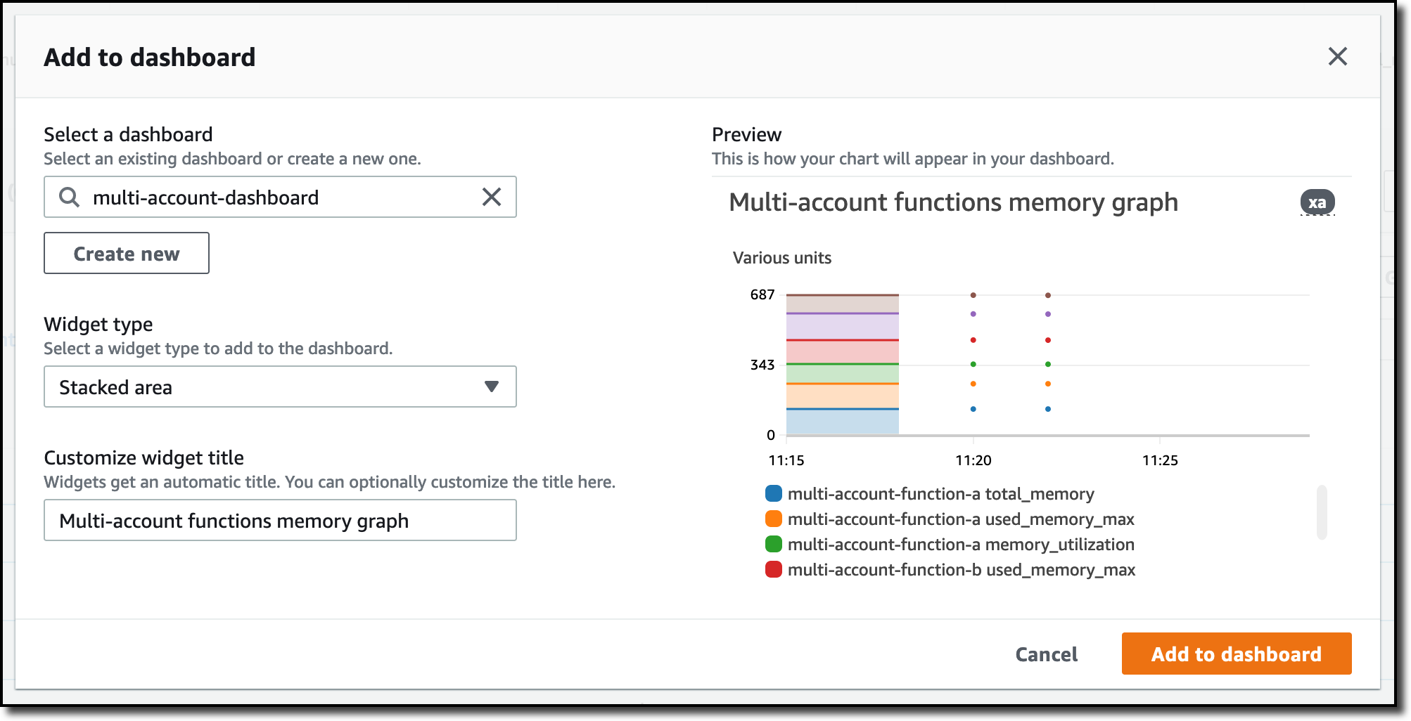
I create a new dashboard and choose the Stacked area widget type. Then, I choose Add to dashboard.

Console screenshot.

I do the same for the CPU and memory metrics (but using different widget types) to quickly create a cross-account dashboard where I can keep under control my multi-account setup. Well, there isn’t a lot of traffic yet but I am hopeful.

Console screenshot.

Finally, I choose Service map from the X-Ray traces section of the navigation pane to see the flow of my multi-account application. In the service map, the client triggers the Lambda function in the source account. Then, an event is sent to the other account to run the other Lambda function.

Console screenshot.

In the service map, I select the gear icon for the function running in the source account (multi-account-function-a) and then View traces to look at the individual traces. The traces contain data from multiple AWS accounts. I can search for traces coming from a specific account using a syntax such as:

service(id(account.id: "123412341234"))

Console screenshot.

The service map now stitches together telemetry from multiple accounts in a single place, delivering a consolidated view to monitor their cross-account applications. This helps me to pinpoint issues quickly and reduces resolution time.

Availability and Pricing
Amazon CloudWatch cross-account observability is available today in all commercial AWS Regions using the AWS Management Console, AWS Command Line Interface (CLI), and AWS SDKs. AWS CloudFormation support is coming in the next few days. Cross-account observability in CloudWatch comes with no extra cost for logs and metrics, and the first trace copy is free. See the Amazon CloudWatch pricing page for details.

Having a central point of view to monitor all the AWS accounts that you use gives you a better understanding of your overall activities and helps solve issues for applications that span multiple accounts.

Start using CloudWatch cross-account observability to monitor all your resources.

Danilo

Microservice observability with Amazon OpenSearch Service part 2: Create an operational panel and incident report

Post Syndicated from Marvin Gersho original https://aws.amazon.com/blogs/big-data/microservice-observability-with-amazon-opensearch-service-part-2-create-an-operational-panel-and-incident-report/

In the first post in our series , we discussed setting up a microservice observability architecture and application troubleshooting steps using log and trace correlation with Amazon OpenSearch Service. In this post, we discuss using PPL to create visualizations in operational panels, and creating a simple incident report using notebooks.

To try out the solution yourself, start from part 1 of the series.

Microservice observability with Amazon OpenSearch Service

Piped Processing Language (PPL)

PPL is a new query language for OpenSearch. It’s simpler and more straightforward to use than query DSL (Domain Specific Language), and a better fit for DevOps than ODFE SQL. PPL handles semi-structured data and uses a sequence of commands delimited by pipes (|). For more information about PPL, refer to Using pipes to explore, discover and find data in Amazon OpenSearch Service with Piped Processing Language.

The following PPL query retrieves the same record as our search on the Discover page in our previous post. If you’re following along, use your trace ID in place of <Trace-ID>:

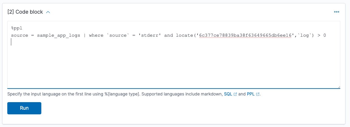
source = sample_app_logs | where stream = 'stderr' and locate(‘<Trace-ID>’,`log`) > 0

The query has the following components:

  • | separates commands in the statement.
  • Source=sample_app_logs means that we’re searching sample_app_logs.
  • where stream = ‘stderr’, stream is a field in sample_app_logs. We’re matching the value to stderr.
  • The locate function allows us to search for a string in a field. For our query, we search for the trace_id in the log field. The locate function returns 0 if the string is not found, otherwise the character number where it is found. We’re testing that trace_id is in the log field. This lets us find the entry that has the payment trace_id with the error.

Note that log is PPL keyword, but also a field in our log file. We put backquotes around a field name if it’s also a keyword if we need to reference it in a PPL statement.

To start using PPL, complete the following steps:

  1. On OpenSearch Dashboards, choose Observability in the navigation pane.
  2. Choose Event analytics.
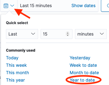
  3. Choose the calendar icon, then choose the time period you want for your query (for this post, Year to date).
  4. Enter your PPL statement.

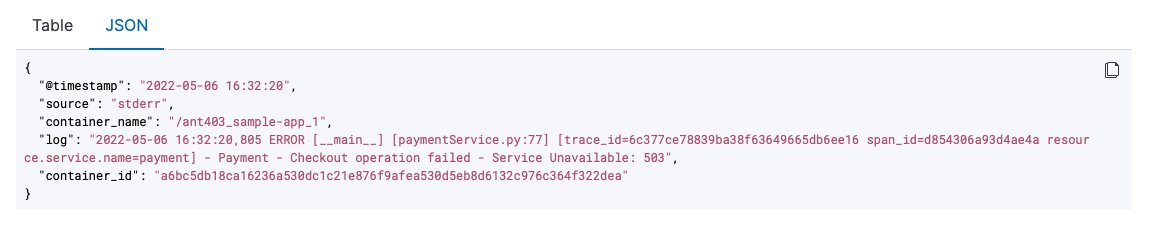
Note that results are shown in table format by default, but you can also choose to view them in JSON format.

Monitor your services using visualizations

We can use the PPL on the Event analytics page to create real-time visualizations. We now use these visualizations to create a dashboard for real-time monitoring of our microservices on the Operational panels page.

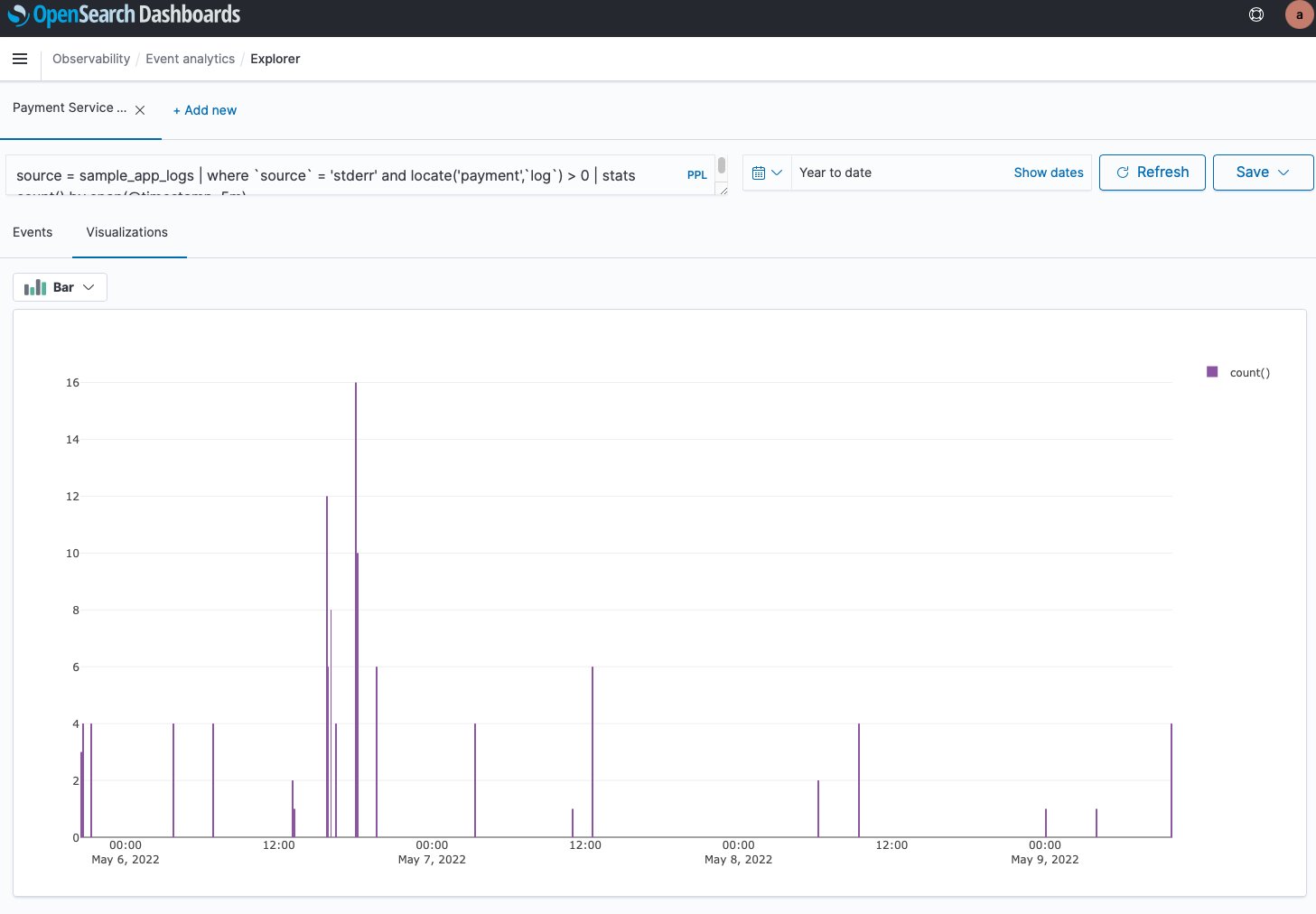
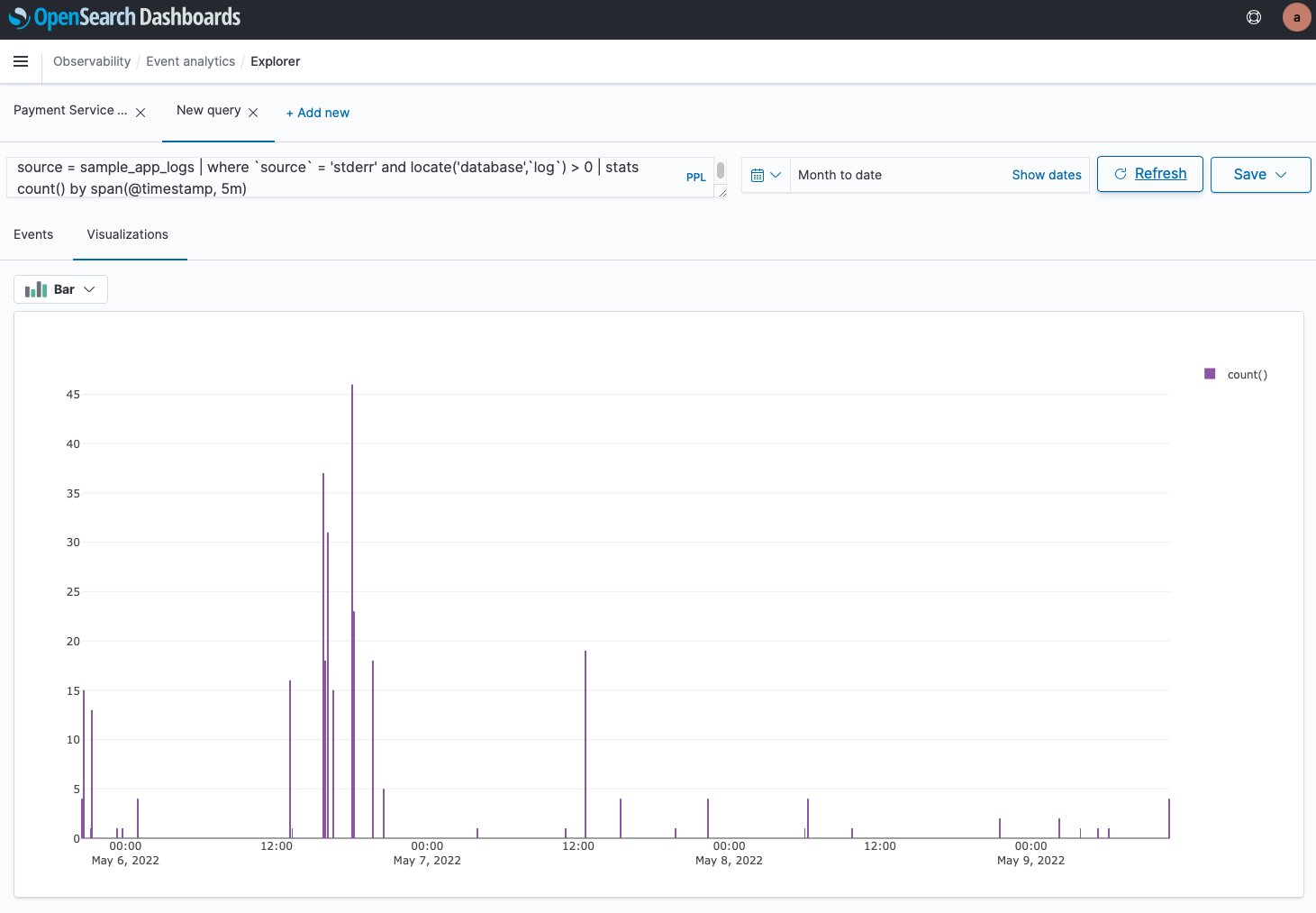
Event analytics has two modes: events and visualizations. With events, we’re looking at the query results as a table or JSON. With visualizations, the results are shown as a graph. For this post, we create a PPL query that monitors a value over time, and see the results in a graph. We can then save the graph to use in our dashboard. See the following code:

source = sample_app_logs | where stream = 'stderr' and locate('payment',`log`) > 0 | stats count() by span(time, 5m)

This code is similar to the PPL we used earlier, with two key differences:

  • We specify the name of our service in the log field (for this post, payment).
  • We use the aggregation function stats count() by span(time, 5m). We take the count of matches in the log field and aggregate by 5-minute intervals.

The following screenshot shows the visualization.

OpenSearch Service offers a choice of several different visualizations, such as line, bar, and pie charts.

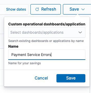
We now save the results as a visualization, giving it the name Payment Service Errors.

We want to create and save a visualization for each of the five services. To create a new visualization, choose Add new, then modify the query by changing the service name.

We save this one and repeat the process by choosing Add new again for each of the five micro-services. Each microservice is now available on its own tab.

Create an operational panel

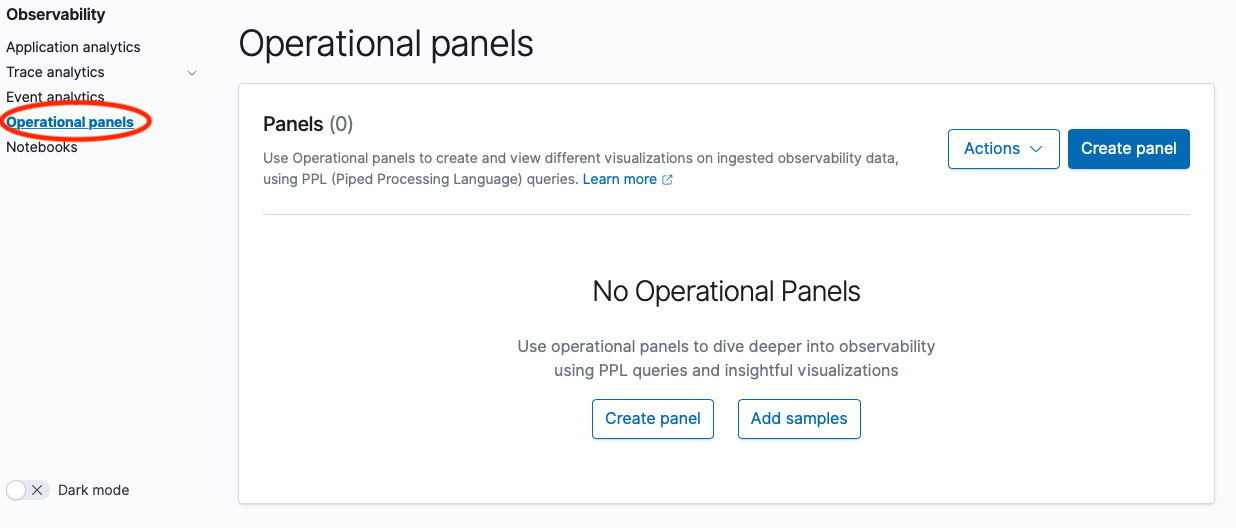
Operational panels in OpenSearch Dashboards are collections of visualizations created using PPL queries. Now that we have created the visualizations in the Event analytics dashboard, we can create a new operational panel.

  1. On the Operational panel page, choose Create panel.
  2. For Name, enter e-Commerce Error Monitoring.
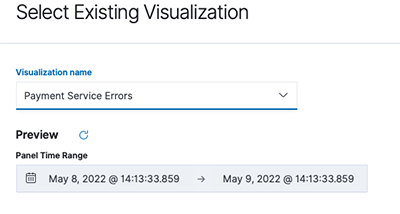
  3. Open that panel and choose Add Visualization.
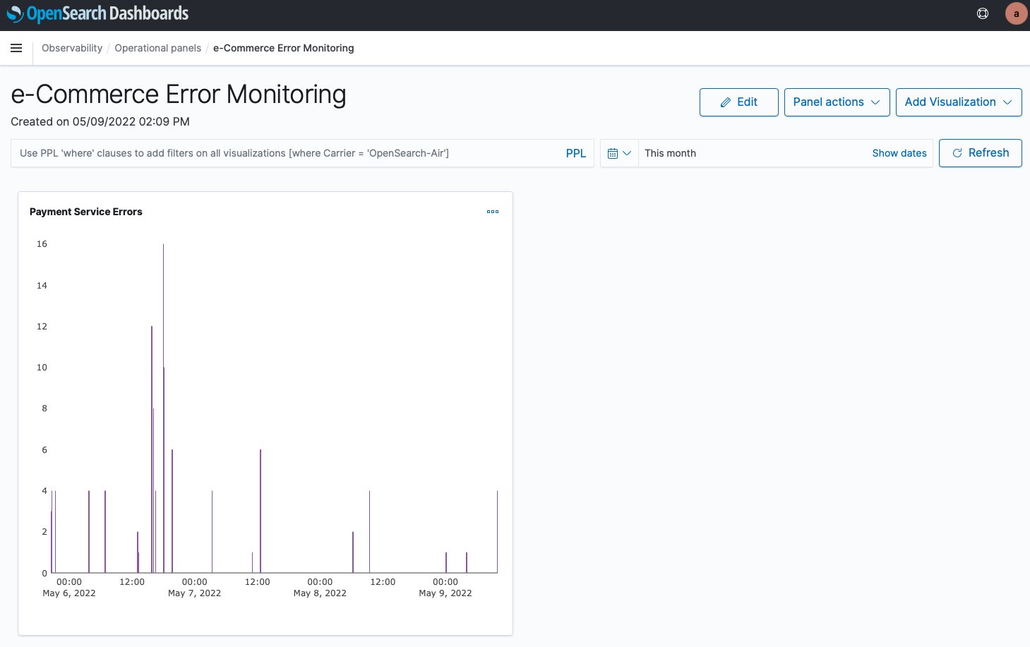
  4. Choose Payment Service Errors.

The following screenshot shows our visualization.

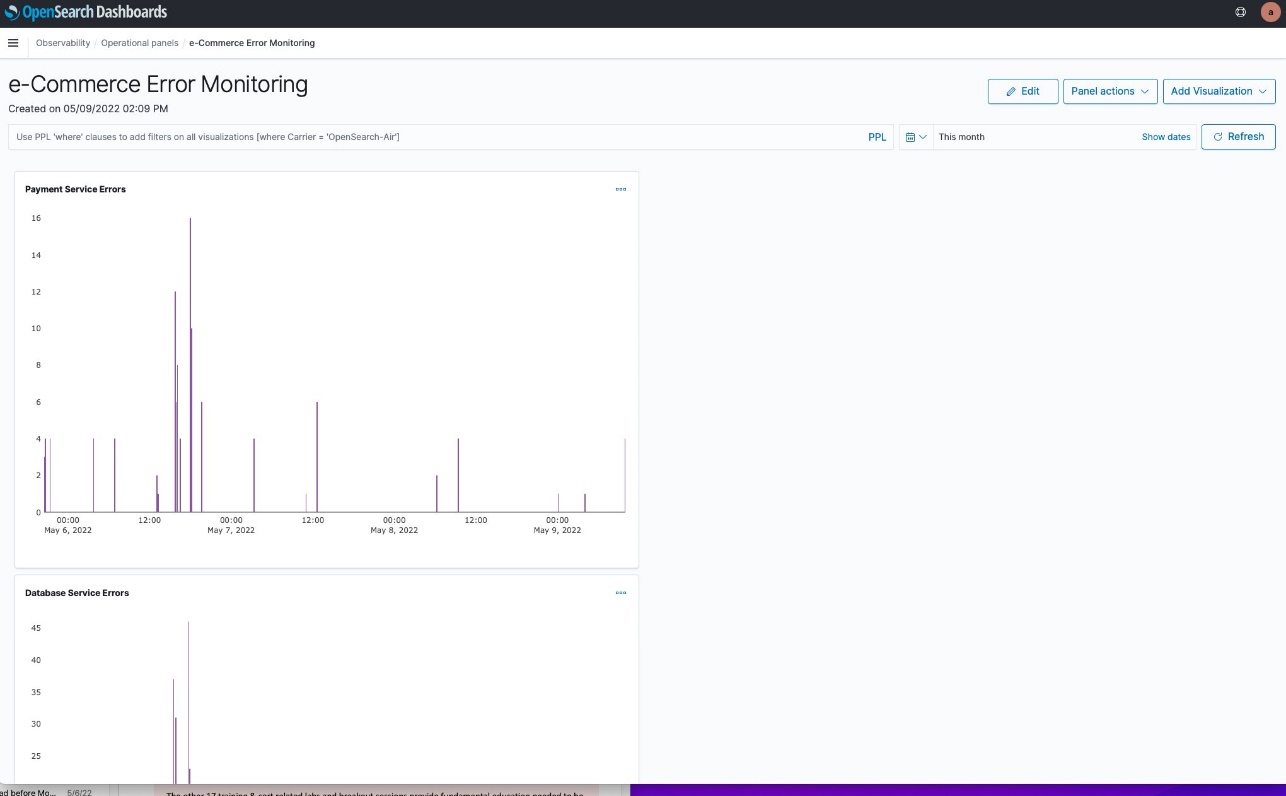
We now repeat the process for our other four services. However, the layout isn’t good. The graphs are too big, and laid out vertically, so they can’t all be seen at once.

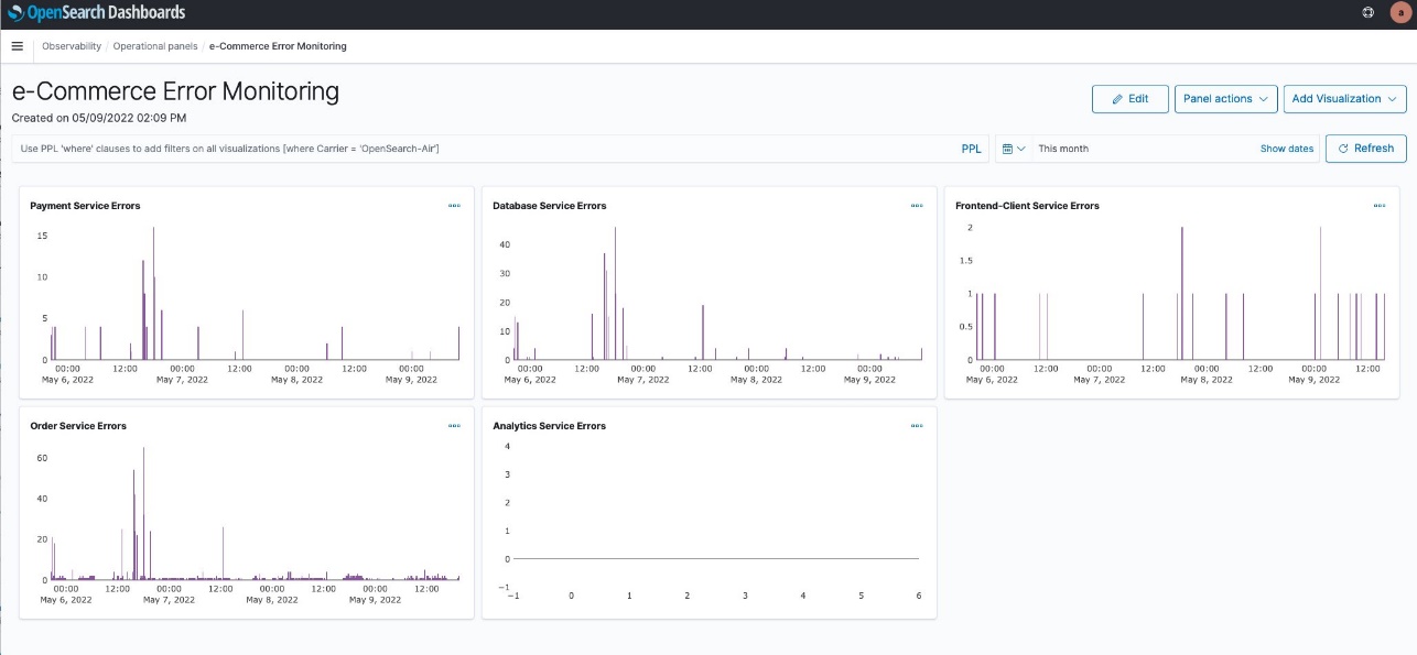
We can choose Edit to adjust the size of each visualization and move them around. We end up with the layout in the following screenshot.

We can now monitor errors over time for all of our services. Notice that the y axis of each service visualization adjusts based on the error count.

This will be a useful tool for monitoring our services in the future.

Next, we create an incident report on the error that we found.

Create an OpenSearch incident report

The e-Commerce Error Monitoring panel can help us monitor our application in the future. However, we want to send out an incident report to our developers about our current findings. We do this by using OpenSearch PPL and Notebooks features introduced in OpenSearch Service 1.3 to create an incident report. A notebook can be downloaded as a PDF. An incident report is useful to share our findings with others.

First, we need to create a new notebook.

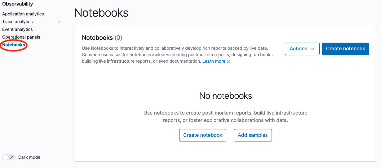
  1. Under Observability in the navigation pane, choose Notebooks.
  2. Choose Create notebook.
  3. For Name, enter e-Commerce Error Report.
  4. Choose Create.

    The following screenshot shows our new notebook page.

    A notebook consists of code blocks: narrative, PPL, and SQL, and visualizations created on the Event analytics page with PPL.
  5. Choose Add code block.
    We can now write a new code block.

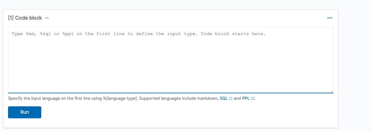
    We can use %md, %sql, or %ppl to add code. In this first block, we just enter text.
  6. Use %md to add narrative text.
  7. Choose Run to see the output.

    The following screenshot shows our code block.

    Now we want to add our PPL query to show the error we found earlier.
  8. On the Add paragraph menu, choose Code block.
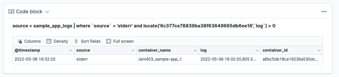
  9. Enter our PPL query, then choose Run.

    The following screenshot shows our output.

    Let’s drill down on the log field to get details of the error.
    We could have many narrative and code blocks, as well as visualizations of PPL queries. Let’s add a visualization.
  10. On the Add paragraph menu, choose Visualization.
  11. Choose Payment Service Errors to view the report we created earlier.

    This visualization shows a pattern of payment service errors this afternoon. Note that we chose a date range because we’re focusing on today’s errors to communicate with the development team.

    Notebook visualizations can be refreshed to provide updated information. The following screenshot shows our visualization an hour later.
    We’re now going to take our completed notebook and export it as a PDF report to share with other teams.
  12. Choose Output only to make the view cleaner to share.
  13. On the Reporting actions menu, choose Download PDF.

We can send this PDF report to the developers supporting the payment service.

Summary

In this post, we used OpenSearch Service v1.3 to create a dashboard to monitor errors in our microservices application. We then created a notebook to use a PPL query on a specific trace ID for a payment service error to provide details, and a graph of payment service errors to visualize the pattern of errors. Finally, we saved our notebook as a PDF to share with the payment service development team. If you would like to explore these features further check out the latest Amazon OpenSearch Observability documentation or, for open source, OpenSearch Observability latest open source documentation. You can also contact your AWS Solutions Architects, who can be of assistance alongside your innovation journey.


About the Authors

Marvin Gersho is a Senior Solutions Architect at AWS based in New York City. He works with a wide range of startup customers. He previously worked for many years in engineering leadership and hands-on application development, and now focuses on helping customers architect secure and scalable workloads on AWS with a minimum of operational overhead. In his free time, Marvin enjoys cycling and strategy board games.

Subham Rakshit is a Streaming Specialist Solutions Architect for Analytics at AWS based in the UK. He works with customers to design and build search and streaming data platforms that help them achieve their business objective. Outside of work, he enjoys spending time solving jigsaw puzzles with his daughter.

Rafael Gumiero is a Senior Analytics Specialist Solutions Architect at AWS. An open-source and distributed systems enthusiast, he provides guidance to customers who develop their solutions with AWS Analytics services, helping them optimize the value of their solutions.

Stream Amazon EMR on EKS logs to third-party providers like Splunk, Amazon OpenSearch Service, or other log aggregators

Post Syndicated from Matthew Tan original https://aws.amazon.com/blogs/big-data/stream-amazon-emr-on-eks-logs-to-third-party-providers-like-splunk-amazon-opensearch-service-or-other-log-aggregators/

Spark jobs running on Amazon EMR on EKS generate logs that are very useful in identifying issues with Spark processes and also as a way to see Spark outputs. You can access these logs from a variety of sources. On the Amazon EMR virtual cluster console, you can access logs from the Spark History UI. You also have flexibility to push logs into an Amazon Simple Storage Service (Amazon S3) bucket or Amazon CloudWatch Logs. In each method, these logs are linked to the specific job in question. The common practice of log management in DevOps culture is to centralize logging through the forwarding of logs to an enterprise log aggregation system like Splunk or Amazon OpenSearch Service (successor to Amazon Elasticsearch Service). This enables you to see all the applicable log data in one place. You can identify key trends, anomalies, and correlated events, and troubleshoot problems faster and notify the appropriate people in a timely fashion.

EMR on EKS Spark logs are generated by Spark and can be accessed via the Kubernetes API and kubectl CLI. Therefore, although it’s possible to install log forwarding agents in the Amazon Elastic Kubernetes Service (Amazon EKS) cluster to forward all Kubernetes logs, which include Spark logs, this can become quite expensive at scale because you get information that may not be important for Spark users about Kubernetes. In addition, from a security point of view, the EKS cluster logs and access to kubectl may not be available to the Spark user.

To solve this problem, this post proposes using pod templates to create a sidecar container alongside the Spark job pods. The sidecar containers are able to access the logs contained in the Spark pods and forward these logs to the log aggregator. This approach allows the logs to be managed separately from the EKS cluster and uses a small amount of resources because the sidecar container is only launched during the lifetime of the Spark job.

Implementing Fluent Bit as a sidecar container

Fluent Bit is a lightweight, highly scalable, and high-speed logging and metrics processor and log forwarder. It collects event data from any source, enriches that data, and sends it to any destination. Its lightweight and efficient design coupled with its many features makes it very attractive to those working in the cloud and in containerized environments. It has been deployed extensively and trusted by many, even in large and complex environments. Fluent Bit has zero dependencies and requires only 650 KB in memory to operate, as compared to FluentD, which needs about 40 MB in memory. Therefore, it’s an ideal option as a log forwarder to forward logs generated from Spark jobs.

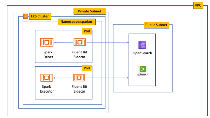
When you submit a job to EMR on EKS, there are at least two Spark containers: the Spark driver and the Spark executor. The number of Spark executor pods depends on your job submission configuration. If you indicate more than one spark.executor.instances, you get the corresponding number of Spark executor pods. What we want to do here is run Fluent Bit as sidecar containers with the Spark driver and executor pods. Diagrammatically, it looks like the following figure. The Fluent Bit sidecar container reads the indicated logs in the Spark driver and executor pods, and forwards these logs to the target log aggregator directly.

Architecture of Fluent Bit sidecar

Pod templates in EMR on EKS

A Kubernetes pod is a group of one or more containers with shared storage, network resources, and a specification for how to run the containers. Pod templates are specifications for creating pods. It’s part of the desired state of the workload resources used to run the application. Pod template files can define the driver or executor pod configurations that aren’t supported in standard Spark configuration. That being said, Spark is opinionated about certain pod configurations and some values in the pod template are always overwritten by Spark. Using a pod template only allows Spark to start with a template pod and not an empty pod during the pod building process. Pod templates are enabled in EMR on EKS when you configure the Spark properties spark.kubernetes.driver.podTemplateFile and spark.kubernetes.executor.podTemplateFile. Spark downloads these pod templates to construct the driver and executor pods.

Forward logs generated by Spark jobs in EMR on EKS

A log aggregating system like Amazon OpenSearch Service or Splunk should always be available that can accept the logs forwarded by the Fluent Bit sidecar containers. If not, we provide the following scripts in this post to help you launch a log aggregating system like Amazon OpenSearch Service or Splunk installed on an Amazon Elastic Compute Cloud (Amazon EC2) instance.

We use several services to create and configure EMR on EKS. We use an AWS Cloud9 workspace to run all the scripts and to configure the EKS cluster. To prepare to run a job script that requires certain Python libraries absent from the generic EMR images, we use Amazon Elastic Container Registry (Amazon ECR) to store the customized EMR container image.

Create an AWS Cloud9 workspace

The first step is to launch and configure the AWS Cloud9 workspace by following the instructions in Create a Workspace in the EKS Workshop. After you create the workspace, we create AWS Identity and Access Management (IAM) resources. Create an IAM role for the workspace, attach the role to the workspace, and update the workspace IAM settings.

Prepare the AWS Cloud9 workspace

Clone the following GitHub repository and run the following script to prepare the AWS Cloud9 workspace to be ready to install and configure Amazon EKS and EMR on EKS. The shell script prepare_cloud9.sh installs all the necessary components for the AWS Cloud9 workspace to build and manage the EKS cluster. These include the kubectl command line tool, eksctl CLI tool, jq, and to update the AWS Command Line Interface (AWS CLI).

$ sudo yum -y install git
$ cd ~ 
$ git clone https://github.com/aws-samples/aws-emr-eks-log-forwarding.git
$ cd aws-emr-eks-log-forwarding
$ cd emreks
$ bash prepare_cloud9.sh

All the necessary scripts and configuration to run this solution are found in the cloned GitHub repository.

Create a key pair

As part of this particular deployment, you need an EC2 key pair to create an EKS cluster. If you already have an existing EC2 key pair, you may use that key pair. Otherwise, you can create a key pair.

Install Amazon EKS and EMR on EKS

After you configure the AWS Cloud9 workspace, in the same folder (emreks), run the following deployment script:

$ bash deploy_eks_cluster_bash.sh 
Deployment Script -- EMR on EKS
-----------------------------------------------

Please provide the following information before deployment:
1. Region (If your Cloud9 desktop is in the same region as your deployment, you can leave this blank)
2. Account ID (If your Cloud9 desktop is running in the same Account ID as where your deployment will be, you can leave this blank)
3. Name of the S3 bucket to be created for the EMR S3 storage location
Region: [xx-xxxx-x]: < Press enter for default or enter region > 
Account ID [xxxxxxxxxxxx]: < Press enter for default or enter account # > 
EC2 Public Key name: < Provide your key pair name here >
Default S3 bucket name for EMR on EKS (do not add s3://): < bucket name >
Bucket created: XXXXXXXXXXX ...
Deploying CloudFormation stack with the following parameters...
Region: xx-xxxx-x | Account ID: xxxxxxxxxxxx | S3 Bucket: XXXXXXXXXXX

...

EKS Cluster and Virtual EMR Cluster have been installed.

The last line indicates that installation was successful.

Log aggregation options

There are several log aggregation and management tools on the market. This post suggests two of the more popular ones in the industry: Splunk and Amazon OpenSearch Service.

Option 1: Install Splunk Enterprise

To manually install Splunk on an EC2 instance, complete the following steps:

  1. Launch an EC2 instance.
  2. Install Splunk.
  3. Configure the EC2 instance security group to permit access to ports 22, 8000, and 8088.

This post, however, provides an automated way to install Spunk on an EC2 instance:

  1. Download the RPM install file and upload it to an accessible Amazon S3 location.
  2. Upload the following YAML script into AWS CloudFormation.
  3. Provide the necessary parameters, as shown in the screenshots below.
  4. Choose Next and complete the steps to create your stack.

Splunk CloudFormation screen - 1

Splunk CloudFormation screen - 2

Splunk CloudFormation screen - 3

Alternatively, run an AWS CLI script like the following:

aws cloudformation create-stack \
--stack-name "splunk" \
--template-body file://splunk_cf.yaml \
--parameters ParameterKey=KeyName,ParameterValue="< Name of EC2 Key Pair >" \
  ParameterKey=InstanceType,ParameterValue="t3.medium" \
  ParameterKey=LatestAmiId,ParameterValue="/aws/service/ami-amazon-linux-latest/amzn2-ami-hvm-x86_64-gp2" \
  ParameterKey=VPCID,ParameterValue="vpc-XXXXXXXXXXX" \
  ParameterKey=PublicSubnet0,ParameterValue="subnet-XXXXXXXXX" \
  ParameterKey=SSHLocation,ParameterValue="< CIDR Range for SSH access >" \
  ParameterKey=VpcCidrRange,ParameterValue="172.20.0.0/16" \
  ParameterKey=RootVolumeSize,ParameterValue="100" \
  ParameterKey=S3BucketName,ParameterValue="< S3 Bucket Name >" \
  ParameterKey=S3Prefix,ParameterValue="splunk/splunk-8.2.5-77015bc7a462-linux-2.6-x86_64.rpm" \
  ParameterKey=S3DownloadLocation,ParameterValue="/tmp" \
--region < region > \
--capabilities CAPABILITY_IAM
  1. After you build the stack, navigate to the stack’s Outputs tab on the AWS CloudFormation console and note the internal and external DNS for the Splunk instance.

You use these later to configure the Splunk instance and log forwarding.

Splunk CloudFormation output screen

  1. To configure Splunk, go to the Resources tab for the CloudFormation stack and locate the physical ID of EC2Instance.
  2. Choose that link to go to the specific EC2 instance.
  3. Select the instance and choose Connect.

Connect to Splunk Instance

  1. On the Session Manager tab, choose Connect.

Connect to Instance

You’re redirected to the instance’s shell.

  1. Install and configure Splunk as follows:
$ sudo /opt/splunk/bin/splunk start --accept-license
…
Please enter an administrator username: admin
Password must contain at least:
   * 8 total printable ASCII character(s).
Please enter a new password: 
Please confirm new password:
…
Done
                                                           [  OK  ]

Waiting for web server at http://127.0.0.1:8000 to be available......... Done
The Splunk web interface is at http://ip-xx-xxx-xxx-x.us-east-2.compute.internal:8000
  1. Enter the Splunk site using the SplunkPublicDns value from the stack outputs (for example, http://ec2-xx-xxx-xxx-x.us-east-2.compute.amazonaws.com:8000). Note the port number of 8000.
  2. Log in with the user name and password you provided.

Splunk Login

Configure HTTP Event Collector

To configure Splunk to be able to receive logs from Fluent Bit, configure the HTTP Event Collector data input:

  1. Go to Settings and choose Data input.
  2. Choose HTTP Event Collector.
  3. Choose Global Settings.
  4. Select Enabled, keep port number 8088, then choose Save.
  5. Choose New Token.
  6. For Name, enter a name (for example, emreksdemo).
  7. Choose Next.
  8. For Available item(s) for Indexes, add at least the main index.
  9. Choose Review and then Submit.
  10. In the list of HTTP Event Collect tokens, copy the token value for emreksdemo.

You use it when configuring the Fluent Bit output.

splunk-http-collector-list

Option 2: Set up Amazon OpenSearch Service

Your other log aggregation option is to use Amazon OpenSearch Service.

Provision an OpenSearch Service domain

Provisioning an OpenSearch Service domain is very straightforward. In this post, we provide a simple script and configuration to provision a basic domain. To do it yourself, refer to Creating and managing Amazon OpenSearch Service domains.

Before you start, get the ARN of the IAM role that you use to run the Spark jobs. If you created the EKS cluster with the provided script, go to the CloudFormation stack emr-eks-iam-stack. On the Outputs tab, locate the IAMRoleArn output and copy this ARN. We also modify the IAM role later on, after we create the OpenSearch Service domain.

iam_role_emr_eks_job

If you’re using the provided opensearch.sh installer, before you run it, modify the file.

From the root folder of the GitHub repository, cd to opensearch and modify opensearch.sh (you can also use your preferred editor):

[../aws-emr-eks-log-forwarding] $ cd opensearch
[../aws-emr-eks-log-forwarding/opensearch] $ vi opensearch.sh

Configure opensearch.sh to fit your environment, for example:

# name of our Amazon OpenSearch cluster
export ES_DOMAIN_NAME="emreksdemo"

# Elasticsearch version
export ES_VERSION="OpenSearch_1.0"

# Instance Type
export INSTANCE_TYPE="t3.small.search"

# OpenSearch Dashboards admin user
export ES_DOMAIN_USER="emreks"

# OpenSearch Dashboards admin password
export ES_DOMAIN_PASSWORD='< ADD YOUR PASSWORD >'

# Region
export REGION='us-east-1'

Run the script:

[../aws-emr-eks-log-forwarding/opensearch] $ bash opensearch.sh

Configure your OpenSearch Service domain

After you set up your OpenSearch service domain and it’s active, make the following configuration changes to allow logs to be ingested into Amazon OpenSearch Service:

  1. On the Amazon OpenSearch Service console, on the Domains page, choose your domain.

Opensearch Domain Console

  1. On the Security configuration tab, choose Edit.

Opensearch Security Configuration

  1. For Access Policy, select Only use fine-grained access control.
  2. Choose Save changes.

The access policy should look like the following code:

{
  "Version": "2012-10-17",
  "Statement": [
    {
      "Effect": "Allow",
      "Principal": {
        "AWS": "*"
      },
      "Action": "es:*",
      "Resource": "arn:aws:es:xx-xxxx-x:xxxxxxxxxxxx:domain/emreksdemo/*"
    }
  ]
}
  1. When the domain is active again, copy the domain ARN.

We use it to configure the Amazon EMR job IAM role we mentioned earlier.

  1. Choose the link for OpenSearch Dashboards URL to enter Amazon OpenSearch Service Dashboards.

Opensearch Main Console

  1. In Amazon OpenSearch Service Dashboards, use the user name and password that you configured earlier in the opensearch.sh file.
  2. Choose the options icon and choose Security under OpenSearch Plugins.

opensearch menu

  1. Choose Roles.
  2. Choose Create role.

opensearch-create-role-button

  1. Enter the new role’s name, cluster permissions, and index permissions. For this post, name the role fluentbit_role and give cluster permissions to the following:
    1. indices:admin/create
    2. indices:admin/template/get
    3. indices:admin/template/put
    4. cluster:admin/ingest/pipeline/get
    5. cluster:admin/ingest/pipeline/put
    6. indices:data/write/bulk
    7. indices:data/write/bulk*
    8. create_index

opensearch-create-role-button

  1. In the Index permissions section, give write permission to the index fluent-*.
  2. On the Mapped users tab, choose Manage mapping.
  3. For Backend roles, enter the Amazon EMR job execution IAM role ARN to be mapped to the fluentbit_role role.
  4. Choose Map.

opensearch-map-backend

  1. To complete the security configuration, go to the IAM console and add the following inline policy to the EMR on EKS IAM role entered in the backend role. Replace the resource ARN with the ARN of your OpenSearch Service domain.
{
    "Version": "2012-10-17",
    "Statement": [
        {
            "Sid": "VisualEditor0",
            "Effect": "Allow",
            "Action": [
                "es:ESHttp*"
            ],
            "Resource": "arn:aws:es:us-east-2:XXXXXXXXXXXX:domain/emreksdemo"
        }
    ]
}

The configuration of Amazon OpenSearch Service is complete and ready for ingestion of logs from the Fluent Bit sidecar container.

Configure the Fluent Bit sidecar container

We need to write two configuration files to configure a Fluent Bit sidecar container. The first is the Fluent Bit configuration itself, and the second is the Fluent Bit sidecar subprocess configuration that makes sure that the sidecar operation ends when the main Spark job ends. The suggested configuration provided in this post is for Splunk and Amazon OpenSearch Service. However, you can configure Fluent Bit with other third-party log aggregators. For more information about configuring outputs, refer to Outputs.

Fluent Bit ConfigMap

The following sample ConfigMap is from the GitHub repo:

apiVersion: v1
kind: ConfigMap
metadata:
  name: fluent-bit-sidecar-config
  namespace: sparkns
  labels:
    app.kubernetes.io/name: fluent-bit
data:
  fluent-bit.conf: |
    [SERVICE]
        Flush         1
        Log_Level     info
        Daemon        off
        Parsers_File  parsers.conf
        HTTP_Server   On
        HTTP_Listen   0.0.0.0
        HTTP_Port     2020

    @INCLUDE input-application.conf
    @INCLUDE input-event-logs.conf
    @INCLUDE output-splunk.conf
    @INCLUDE output-opensearch.conf

  input-application.conf: |
    [INPUT]
        Name              tail
        Path              /var/log/spark/user/*/*
        Path_Key          filename
        Buffer_Chunk_Size 1M
        Buffer_Max_Size   5M
        Skip_Long_Lines   On
        Skip_Empty_Lines  On

  input-event-logs.conf: |
    [INPUT]
        Name              tail
        Path              /var/log/spark/apps/*
        Path_Key          filename
        Buffer_Chunk_Size 1M
        Buffer_Max_Size   5M
        Skip_Long_Lines   On
        Skip_Empty_Lines  On

  output-splunk.conf: |
    [OUTPUT]
        Name            splunk
        Match           *
        Host            < INTERNAL DNS of Splunk EC2 Instance >
        Port            8088
        TLS             On
        TLS.Verify      Off
        Splunk_Token    < Token as provided by the HTTP Event Collector in Splunk >

  output-opensearch.conf: |
[OUTPUT]
        Name            es
        Match           *
        Host            < HOST NAME of the OpenSearch Domain | No HTTP protocol >
        Port            443
        TLS             On
        AWS_Auth        On
        AWS_Region      < Region >
        Retry_Limit     6

In your AWS Cloud9 workspace, modify the ConfigMap accordingly. Provide the values for the placeholder text by running the following commands to enter the VI editor mode. If preferred, you can use PICO or a different editor:

[../aws-emr-eks-log-forwarding] $  cd kube/configmaps
[../aws-emr-eks-log-forwarding/kube/configmaps] $ vi emr_configmap.yaml

# Modify the emr_configmap.yaml as above
# Save the file once it is completed

Complete either the Splunk output configuration or the Amazon OpenSearch Service output configuration.

Next, run the following commands to add the two Fluent Bit sidecar and subprocess ConfigMaps:

[../aws-emr-eks-log-forwarding/kube/configmaps] $ kubectl apply -f emr_configmap.yaml
[../aws-emr-eks-log-forwarding/kube/configmaps] $ kubectl apply -f emr_entrypoint_configmap.yaml

You don’t need to modify the second ConfigMap because it’s the subprocess script that runs inside the Fluent Bit sidecar container. To verify that the ConfigMaps have been installed, run the following command:

$ kubectl get cm -n sparkns
NAME                         DATA   AGE
fluent-bit-sidecar-config    6      15s
fluent-bit-sidecar-wrapper   2      15s

Set up a customized EMR container image

To run the sample PySpark script, the script requires the Boto3 package that’s not available in the standard EMR container images. If you want to run your own script and it doesn’t require a customized EMR container image, you may skip this step.

Run the following script:

[../aws-emr-eks-log-forwarding] $ cd ecr
[../aws-emr-eks-log-forwarding/ecr] $ bash create_custom_image.sh <region> <EMR container image account number>

The EMR container image account number can be obtained from How to select a base image URI. This documentation also provides the appropriate ECR registry account number. For example, the registry account number for us-east-1 is 755674844232.

To verify the repository and image, run the following commands:

$ aws ecr describe-repositories --region < region > | grep emr-6.5.0-custom
            "repositoryArn": "arn:aws:ecr:xx-xxxx-x:xxxxxxxxxxxx:repository/emr-6.5.0-custom",
            "repositoryName": "emr-6.5.0-custom",
            "repositoryUri": " xxxxxxxxxxxx.dkr.ecr.xx-xxxx-x.amazonaws.com/emr-6.5.0-custom",

$ aws ecr describe-images --region < region > --repository-name emr-6.5.0-custom | jq .imageDetails[0].imageTags
[
  "latest"
]

Prepare pod templates for Spark jobs

Upload the two Spark driver and Spark executor pod templates to an S3 bucket and prefix. The two pod templates can be found in the GitHub repository:

  • emr_driver_template.yaml – Spark driver pod template
  • emr_executor_template.yaml – Spark executor pod template

The pod templates provided here should not be modified.

Submitting a Spark job with a Fluent Bit sidecar container

This Spark job example uses the bostonproperty.py script. To use this script, upload it to an accessible S3 bucket and prefix and complete the preceding steps to use an EMR customized container image. You also need to upload the CSV file from the GitHub repo, which you need to download and unzip. Upload the unzipped file to the following location: s3://<your chosen bucket>/<first level folder>/data/boston-property-assessment-2021.csv.

The following commands assume that you launched your EKS cluster and virtual EMR cluster with the parameters indicated in the GitHub repo.

Variable Where to Find the Information or the Value Required
EMR_EKS_CLUSTER_ID Amazon EMR console virtual cluster page
EMR_EKS_EXECUTION_ARN IAM role ARN
EMR_RELEASE emr-6.5.0-latest
S3_BUCKET The bucket you create in Amazon S3
S3_FOLDER The preferred prefix you want to use in Amazon S3
CONTAINER_IMAGE The URI in Amazon ECR where your container image is
SCRIPT_NAME emreksdemo-script or a name you prefer

Alternatively, use the provided script to run the job. Change the directory to the scripts folder in emreks and run the script as follows:

[../aws-emr-eks-log-forwarding] cd emreks/scripts
[../aws-emr-eks-log-forwarding/emreks/scripts] bash run_emr_script.sh < S3 bucket name > < ECR container image > < script path>

Example: bash run_emr_script.sh emreksdemo-123456 12345678990.dkr.ecr.us-east-2.amazonaws.com/emr-6.5.0-custom s3://emreksdemo-123456/scripts/scriptname.py

After you submit the Spark job successfully, you get a return JSON response like the following:

{
    "id": "0000000305e814v0bpt",
    "name": "emreksdemo-job",
    "arn": "arn:aws:emr-containers:xx-xxxx-x:XXXXXXXXXXX:/virtualclusters/upobc00wgff5XXXXXXXXXXX/jobruns/0000000305e814v0bpt",
    "virtualClusterId": "upobc00wgff5XXXXXXXXXXX"
}

What happens when you submit a Spark job with a sidecar container

After you submit a Spark job, you can see what is happening by viewing the pods that are generated and the corresponding logs. First, using kubectl, get a list of the pods generated in the namespace where the EMR virtual cluster runs. In this case, it’s sparkns. The first pod in the following code is the job controller for this particular Spark job. The second pod is the Spark executor; there can be more than one pod depending on how many executor instances are asked for in the Spark job setting—we asked for one here. The third pod is the Spark driver pod.

$ kubectl get pods -n sparkns
NAME                                        READY   STATUS    RESTARTS   AGE
0000000305e814v0bpt-hvwjs                   3/3     Running   0          25s
emreksdemo-script-1247bf80ae40b089-exec-1   0/3     Pending   0          0s
spark-0000000305e814v0bpt-driver            3/3     Running   0          11s

To view what happens in the sidecar container, follow the logs in the Spark driver pod and refer to the sidecar. The sidecar container launches with the Spark pods and persists until the file /var/log/fluentd/main-container-terminated is no longer available. For more information about how Amazon EMR controls the pod lifecycle, refer to Using pod templates. The subprocess script ties the sidecar container to this same lifecycle and deletes itself upon the EMR controlled pod lifecycle process.

$ kubectl logs spark-0000000305e814v0bpt-driver -n sparkns  -c custom-side-car-container --follow=true

Waiting for file /var/log/fluentd/main-container-terminated to appear...
AWS for Fluent Bit Container Image Version 2.24.0Start wait: 1652190909
Elapsed Wait: 0
Not found count: 0
Waiting...
Fluent Bit v1.9.3
* Copyright (C) 2015-2022 The Fluent Bit Authors
* Fluent Bit is a CNCF sub-project under the umbrella of Fluentd
* https://fluentbit.io

[2022/05/10 13:55:09] [ info] [fluent bit] version=1.9.3, commit=9eb4996b7d, pid=11
[2022/05/10 13:55:09] [ info] [storage] version=1.2.0, type=memory-only, sync=normal, checksum=disabled, max_chunks_up=128
[2022/05/10 13:55:09] [ info] [cmetrics] version=0.3.1
[2022/05/10 13:55:09] [ info] [output:splunk:splunk.0] worker #0 started
[2022/05/10 13:55:09] [ info] [output:splunk:splunk.0] worker #1 started
[2022/05/10 13:55:09] [ info] [output:es:es.1] worker #0 started
[2022/05/10 13:55:09] [ info] [output:es:es.1] worker #1 started
[2022/05/10 13:55:09] [ info] [http_server] listen iface=0.0.0.0 tcp_port=2020
[2022/05/10 13:55:09] [ info] [sp] stream processor started
Waiting for file /var/log/fluentd/main-container-terminated to appear...
Last heartbeat: 1652190914
Elapsed Time since after heartbeat: 0
Found count: 0
list files:
-rw-r--r-- 1 saslauth 65534 0 May 10 13:55 /var/log/fluentd/main-container-terminated
Last heartbeat: 1652190918

…

[2022/05/10 13:56:09] [ info] [input:tail:tail.0] inotify_fs_add(): inode=58834691 watch_fd=6 name=/var/log/spark/user/spark-0000000305e814v0bpt-driver/stdout-s3-container-log-in-tail.pos
[2022/05/10 13:56:09] [ info] [input:tail:tail.1] inotify_fs_add(): inode=54644346 watch_fd=1 name=/var/log/spark/apps/spark-0000000305e814v0bpt
Outside of loop, main-container-terminated file no longer exists
ls: cannot access /var/log/fluentd/main-container-terminated: No such file or directory
The file /var/log/fluentd/main-container-terminated doesn't exist anymore;
TERMINATED PROCESS
Fluent-Bit pid: 11
Killing process after sleeping for 15 seconds
root        11     8  0 13:55 ?        00:00:00 /fluent-bit/bin/fluent-bit -e /fluent-bit/firehose.so -e /fluent-bit/cloudwatch.so -e /fluent-bit/kinesis.so -c /fluent-bit/etc/fluent-bit.conf
root       114     7  0 13:56 ?        00:00:00 grep fluent
Killing process 11
[2022/05/10 13:56:24] [engine] caught signal (SIGTERM)
[2022/05/10 13:56:24] [ info] [input] pausing tail.0
[2022/05/10 13:56:24] [ info] [input] pausing tail.1
[2022/05/10 13:56:24] [ warn] [engine] service will shutdown in max 5 seconds
[2022/05/10 13:56:25] [ info] [engine] service has stopped (0 pending tasks)
[2022/05/10 13:56:25] [ info] [input:tail:tail.1] inotify_fs_remove(): inode=54644346 watch_fd=1
[2022/05/10 13:56:25] [ info] [input:tail:tail.0] inotify_fs_remove(): inode=60917120 watch_fd=1
[2022/05/10 13:56:25] [ info] [input:tail:tail.0] inotify_fs_remove(): inode=60917121 watch_fd=2
[2022/05/10 13:56:25] [ info] [input:tail:tail.0] inotify_fs_remove(): inode=58834690 watch_fd=3
[2022/05/10 13:56:25] [ info] [input:tail:tail.0] inotify_fs_remove(): inode=58834692 watch_fd=4
[2022/05/10 13:56:25] [ info] [input:tail:tail.0] inotify_fs_remove(): inode=58834689 watch_fd=5
[2022/05/10 13:56:25] [ info] [input:tail:tail.0] inotify_fs_remove(): inode=58834691 watch_fd=6
[2022/05/10 13:56:25] [ info] [output:splunk:splunk.0] thread worker #0 stopping...
[2022/05/10 13:56:25] [ info] [output:splunk:splunk.0] thread worker #0 stopped
[2022/05/10 13:56:25] [ info] [output:splunk:splunk.0] thread worker #1 stopping...
[2022/05/10 13:56:25] [ info] [output:splunk:splunk.0] thread worker #1 stopped
[2022/05/10 13:56:25] [ info] [output:es:es.1] thread worker #0 stopping...
[2022/05/10 13:56:25] [ info] [output:es:es.1] thread worker #0 stopped
[2022/05/10 13:56:25] [ info] [output:es:es.1] thread worker #1 stopping...
[2022/05/10 13:56:25] [ info] [output:es:es.1] thread worker #1 stopped

View the forwarded logs in Splunk or Amazon OpenSearch Service

To view the forwarded logs, do a search in Splunk or on the Amazon OpenSearch Service console. If you’re using a shared log aggregator, you may have to filter the results. In this configuration, the logs tailed by Fluent Bit are in the /var/log/spark/*. The following screenshots show the logs generated specifically by the Kubernetes Spark driver stdout that were forwarded to the log aggregators. You can compare the results with the logs provided using kubectl:

kubectl logs < Spark Driver Pod > -n < namespace > -c spark-kubernetes-driver --follow=true

…
root
 |-- PID: string (nullable = true)
 |-- CM_ID: string (nullable = true)
 |-- GIS_ID: string (nullable = true)
 |-- ST_NUM: string (nullable = true)
 |-- ST_NAME: string (nullable = true)
 |-- UNIT_NUM: string (nullable = true)
 |-- CITY: string (nullable = true)
 |-- ZIPCODE: string (nullable = true)
 |-- BLDG_SEQ: string (nullable = true)
 |-- NUM_BLDGS: string (nullable = true)
 |-- LUC: string (nullable = true)
…

|02108|RETAIL CONDO           |361450.0            |63800.0        |5977500.0      |
|02108|RETAIL STORE DETACH    |2295050.0           |988200.0       |3601900.0      |
|02108|SCHOOL                 |1.20858E7           |1.20858E7      |1.20858E7      |
|02108|SINGLE FAM DWELLING    |5267156.561085973   |1153400.0      |1.57334E7      |
+-----+-----------------------+--------------------+---------------+---------------+
only showing top 50 rows

The following screenshot shows the Splunk logs.

splunk-result-driver-stdout

The following screenshots show the Amazon OpenSearch Service logs.

opensearch-result-driver-stdout

Optional: Include a buffer between Fluent Bit and the log aggregators

If you expect to generate a lot of logs because of high concurrent Spark jobs creating multiple individual connects that may overwhelm your Amazon OpenSearch Service or Splunk log aggregation clusters, consider employing a buffer between the Fluent Bit sidecars and your log aggregator. One option is to use Amazon Kinesis Data Firehose as the buffering service.

Kinesis Data Firehose has built-in delivery to both Amazon OpenSearch Service and Splunk. If using Amazon OpenSearch Service, refer to Loading streaming data from Amazon Kinesis Data Firehose. If using Splunk, refer to Configure Amazon Kinesis Firehose to send data to the Splunk platform and Choose Splunk for Your Destination.

To configure Fluent Bit to Kinesis Data Firehose, add the following to your ConfigMap output. Refer to the GitHub ConfigMap example and add the @INCLUDE under the [SERVICE] section:

     @INCLUDE output-kinesisfirehose.conf
…

  output-kinesisfirehose.conf: |
    [OUTPUT]
        Name            kinesis_firehose
        Match           *
        region          < region >
        delivery_stream < Kinesis Firehose Stream Name >

Optional: Use data streams for Amazon OpenSearch Service

If you’re in a scenario where the number of documents grows rapidly and you don’t need to update older documents, you need to manage the OpenSearch Service cluster. This involves steps like creating a rollover index alias, defining a write index, and defining common mappings and settings for the backing indexes. Consider using data streams to simplify this process and enforce a setup that best suits your time series data. For instructions on implementing data streams, refer to Data streams.

Clean up

To avoid incurring future charges, delete the resources by deleting the CloudFormation stacks that were created with this script. This removes the EKS cluster. However, before you do that, remove the EMR virtual cluster first by running the delete-virtual-cluster command. Then delete all the CloudFormation stacks generated by the deployment script.

If you launched an OpenSearch Service domain, you can delete the domain from the OpenSearch Service domain. If you used the script to launch a Splunk instance, you can go to the CloudFormation stack that launched the Splunk instance and delete the CloudFormation stack. This removes remove the Splunk instance and associated resources.

You can also use the following scripts to clean up resources:

Conclusion

EMR on EKS facilitates running Spark jobs on Kubernetes to achieve very fast and cost-efficient Spark operations. This is made possible through scheduling transient pods that are launched and then deleted the jobs are complete. To log all these operations in the same lifecycle of the Spark jobs, this post provides a solution using pod templates and Fluent Bit that is lightweight and powerful. This approach offers a decoupled way of log forwarding based at the Spark application level and not at the Kubernetes cluster level. It also avoids routing through intermediaries like CloudWatch, reducing cost and complexity. In this way, you can address security concerns and DevOps and system administration ease of management while providing Spark users with insights into their Spark jobs in a cost-efficient and functional way.

If you have questions or suggestions, please leave a comment.


About the Author

Matthew Tan is a Senior Analytics Solutions Architect at Amazon Web Services and provides guidance to customers developing solutions with AWS Analytics services on their analytics workloads.                       

Query and visualize Amazon Redshift operational metrics using the Amazon Redshift plugin for Grafana

Post Syndicated from Sergey Konoplev original https://aws.amazon.com/blogs/big-data/query-and-visualize-amazon-redshift-operational-metrics-using-the-amazon-redshift-plugin-for-grafana/

Grafana is a rich interactive open-source tool by Grafana Labs for visualizing data across one or many data sources. It’s used in a variety of modern monitoring stacks, allowing you to have a common technical base and apply common monitoring practices across different systems. Amazon Managed Grafana is a fully managed, scalable, and secure Grafana-as-a-service solution developed by AWS in collaboration with Grafana Labs.

Amazon Redshift is the most widely used data warehouse in the cloud. You can view your Amazon Redshift cluster’s operational metrics on the Amazon Redshift console, use AWS CloudWatch, and query Amazon Redshift system tables directly from your cluster. The first two options provide a set of predefined general metrics and visualizations. The last one allows you to use the flexibility of SQL to get deep insights into the details of the workload. However, querying system tables requires knowledge of system table structures. To address that, we came up with a consolidated Amazon Redshift Grafana dashboard that visualizes a set of curated operational metrics and works on top of the Amazon Redshift Grafana data source. You can easily add it to an Amazon Managed Grafana workspace, as well as to any other Grafana deployments where the data source is installed.

This post guides you through a step-by-step process to create an Amazon Managed Grafana workspace and configure an Amazon Redshift cluster with a Grafana data source for it. Lastly, we show you how to set up the Amazon Redshift Grafana dashboard to visualize the cluster metrics.

Solution overview

The following diagram illustrates the solution architecture.

Architecture Diagram

The solution includes the following components:

  • The Amazon Redshift cluster to get the metrics from.
  • Amazon Managed Grafana, with the Amazon Redshift data source plugin added to it. Amazon Managed Grafana communicates with the Amazon Redshift cluster via the Amazon Redshift Data Service API.
  • The Grafana web UI, with the Amazon Redshift dashboard using the Amazon Redshift cluster as the data source. The web UI communicates with Amazon Managed Grafana via an HTTP API.

We walk you through the following steps during the configuration process:

  1. Configure an Amazon Redshift cluster.
  2. Create a database user for Amazon Managed Grafana on the cluster.
  3. Configure a user in AWS Single Sign-On (AWS SSO) for Amazon Managed Grafana UI access.
  4. Configure an Amazon Managed Grafana workspace and sign in to Grafana.
  5. Set up Amazon Redshift as the data source in Grafana.
  6. Import the Amazon Redshift dashboard supplied with the data source.

Prerequisites

To follow along with this walkthrough, you should have the following prerequisites:

  • An AWS account
  • Familiarity with the basic concepts of the following services:
    • Amazon Redshift
    • Amazon Managed Grafana
    • AWS SSO

Configure an Amazon Redshift cluster

If you don’t have an Amazon Redshift cluster, create a sample cluster before proceeding with the following steps. For this post, we assume that the cluster identifier is called redshift-demo-cluster-1 and the admin user name is awsuser.

  1. On the Amazon Redshift console, choose Clusters in the navigation pane.
  2. Choose your cluster.
  3. Choose the Properties tab.

Redshift Cluster Properties

To make the cluster discoverable by Amazon Managed Grafana, you must add a special tag to it.

  1. Choose Add tags. Redshift Cluster Tags
  2. For Key, enter GrafanaDataSource.
  3. For Value, enter true.
  4. Choose Save changes.

Redshift Cluster Tags

Create a database user for Amazon Managed Grafana

Grafana will be directly querying the cluster, and it requires a database user to connect to the cluster. In this step, we create the user redshift_data_api_user and apply some security best practices.

  1. On the cluster details page, choose Query data and Query in query editor v2.Query Editor v2
  2. Choose the redshift-demo-cluster-1 cluster we created previously.
  3. For Database, enter the default dev.
  4. Enter the user name and password that you used to create the cluster.
  5. Choose Create connection.Redshift SU
  6. In the query editor, enter the following statements and choose Run:
CREATE USER redshift_data_api_user PASSWORD '&lt;password&gt;' CREATEUSER;
ALTER USER redshift_data_api_user SET readonly TO TRUE;
ALTER USER redshift_data_api_user SET query_group TO 'superuser';

The first statement creates a user with superuser privileges necessary to access system tables and views (make sure to use a unique password). The second prohibits the user from making modifications. The last statement isolates the queries the user can run to the superuser queue, so they don’t interfere with the main workload.

In this example, we use service managed permissions in Amazon Managed Grafana and a workspace AWS Identity and Access Management (IAM) role as an authentication provider in the Amazon Redshift Grafana data source. We create the database user redshift_data_api_user using the AmazonGrafanaRedshiftAccess policy.

Configure a user in AWS SSO for Amazon Managed Grafana UI access

Two authentication methods are available for accessing Amazon Managed Grafana: AWS SSO and SAML. In this example, we use AWS SSO.

  1. On the AWS SSO console, choose Users in the navigation pane.
  2. Choose Add user.
  3. In the Add user section, provide the required information.

SSO add user

In this post, we select Send an email to the user with password setup instructions. You need to be able to access the email address you enter because you use this email further in the process.

  1. Choose Next to proceed to the next step.
  2. Choose Add user.

An email is sent to the email address you specified.

  1. Choose Accept invitation in the email.

You’re redirected to sign in as a new user and set a password for the user.

  1. Enter a new password and choose Set new password to finish the user creation.

Configure an Amazon Managed Grafana workspace and sign in to Grafana

Now you’re ready to set up an Amazon Managed Grafana workspace.

  1. On the Amazon Grafana console, choose Create workspace.
  2. For Workspace name, enter a name, for example grafana-demo-workspace-1.
  3. Choose Next.
  4. For Authentication access, select AWS Single Sign-On.
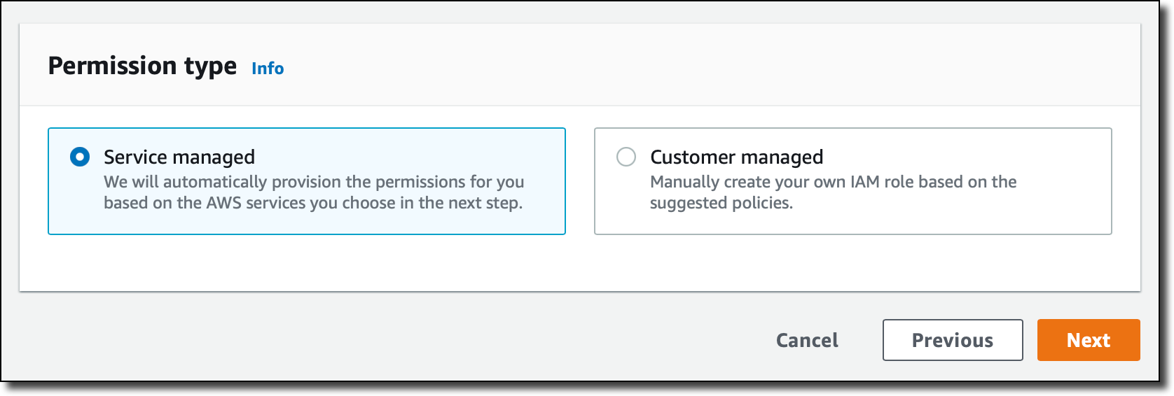
  5. For Permission type, select Service managed.
  6. Chose Next to proceed.AMG Workspace configure
  7. For IAM permission access settings, select Current account.AMG permission
  8. For Data sources, select Amazon Redshift.
  9. Choose Next to finish the workspace creation.Redshift to workspace

You’re redirected to the workspace page.

Next, we need to enable AWS SSO as an authentication method.

  1. On the workspace page, choose Assign new user or group.SSO new user
  2. Select the previously created AWS SSO user under Users and Select users and groups tables.SSO User

You need to make the user an admin, because we set up the Amazon Redshift data source with it.

  1. Select the user from the Users list and choose Make admin.
  2. Go back to the workspace and choose the Grafana workspace URL link to open the Grafana UI.AMG workspace
  3. Sign in with the user name and password you created in the AWS SSO configuration step.

Set up an Amazon Redshift data source in Grafana

To visualize the data in Grafana, we need to access the data first. To do so, we must create a data source pointing to the Amazon Redshift cluster.

  1. On the navigation bar, choose the lower AWS icon (there are two) and then choose Redshift from the list.
  2. For Regions, choose the Region of your cluster.
  3. Select the cluster from the list and choose Add 1 data source.Choose Redshift Cluster
  4. On the Provisioned data sources page, choose Go to settings.
  5. For Name, enter a name for your data source.
  6. By default, Authentication Provider should be set as Workspace IAM Role, Default Region should be the Region of your cluster, and Cluster Identifier should be the name of the chosen cluster.
  7. For Database, enter dev.
  8. For Database User, enter redshift_data_api_user.
  9. Choose Save & Test.Settings for Data Source

A success message should appear.

Data source working

Import the Amazon Redshift dashboard supplied with the data source

As the last step, we import the default Amazon Redshift dashboard and make sure that it works.

  1. In the data source we just created, choose Dashboards on the top navigation bar and choose Import to import the Amazon Redshift dashboard.Dashboards in the plugin
  2. Under Dashboards on the navigation sidebar, choose Manage.
  3. In the dashboards list, choose Amazon Redshift.

The dashboard appear, showing operational data from your cluster. When you add more clusters and create data sources for them in Grafana, you can choose them from the Data source list on the dashboard.

Clean up

To avoid incurring unnecessary charges, delete the Amazon Redshift cluster, AWS SSO user, and Amazon Managed Grafana workspace resources that you created as part of this solution.

Conclusion

In this post, we covered the process of setting up an Amazon Redshift dashboard working under Amazon Managed Grafana with AWS SSO authentication and querying from the Amazon Redshift cluster under the same AWS account. This is just one way to create the dashboard. You can modify the process to set it up with SAML as an authentication method, use custom IAM roles to manage permissions with more granularity, query Amazon Redshift clusters outside of the AWS account where the Grafana workspace is, use an access key and secret or AWS Secrets Manager based connection credentials in data sources, and more. You can also customize the dashboard by adding or altering visualizations using the feature-rich Grafana UI.

Because the Amazon Redshift data source plugin is an open-source project, you can install it in any Grafana deployment, whether it’s in the cloud, on premises, or even in a container running on your laptop. That allows you to seamlessly integrate Amazon Redshift monitoring into virtually all your existing Grafana-based monitoring stacks.

For more details about the systems and processes described in this post, refer to the following:


About the Authors

Sergey Konoplev is a Senior Database Engineer on the Amazon Redshift team. Sergey has been focusing on automation and improvement of database and data operations for more than a decade.

Milind Oke is a Data Warehouse Specialist Solutions Architect based out of New York. He has been building data warehouse solutions for over 15 years and specializes in Amazon Redshift.

Amazon Managed Grafana Is Now Generally Available with Many New Features

Post Syndicated from Danilo Poccia original https://aws.amazon.com/blogs/aws/amazon-managed-grafana-is-now-generally-available-with-many-new-features/

In December, we introduced the preview of Amazon Managed Grafana, a fully managed service developed in collaboration with Grafana Labs that makes it easy to use the open-source and the enterprise versions of Grafana to visualize and analyze your data from multiple sources. With Amazon Managed Grafana, you can analyze your metrics, logs, and traces without having to provision servers, or configure and update software.

During the preview, Amazon Managed Grafana was updated with new capabilities. Today, I am happy to announce that Amazon Managed Grafana is now generally available with additional new features:

  • Grafana has been upgraded to version 8 and offers new data sources, visualizations, and features, including library panels that you can build once and re-use on multiple dashboards, a Prometheus metrics browser to quickly find and query metrics, and new state timeline and status history visualizations.
  • To centralize the querying of additional data sources within an Amazon Managed Grafana workspace, you can now query data using the JSON data source plugin. You can now also query Redis, SAP HANA, Salesforce, ServiceNow, Atlassian Jira, and many more data sources.
  • You can use Grafana API keys to publish your own dashboards or give programmatic access to your Grafana workspace. For example, this is a Terraform recipe that you can use to add data sources and dashboards.
  • You can enable single sign-on to your Amazon Managed Grafana workspaces using Security Assertion Markup Language 2.0 (SAML 2.0). We have worked with these identity providers (IdP) to have them integrated at launch: CyberArk, Okta, OneLogin, Ping Identity, and Azure Active Directory.
  • All calls from the Amazon Managed Grafana console and code calls to Amazon Managed Grafana API operations are captured by AWS CloudTrail. In this way, you can have a record of actions taken in Amazon Managed Grafana by a user, role, or AWS service. Additionally, you can now audit mutating changes that occur in your Amazon Managed Grafana workspace, such as when a dashboard is deleted or data source permissions are changed.
  • The service is available in ten AWS Regions (full list at the end of the post).

Let’s do a quick walkthrough to see how this works in practice.

Using Amazon Managed Grafana
In the Amazon Managed Grafana console, I choose Create workspace. A workspace is a logically isolated, highly available Grafana server. I enter a name and a description for the workspace, and then choose Next.

Console screenshot.

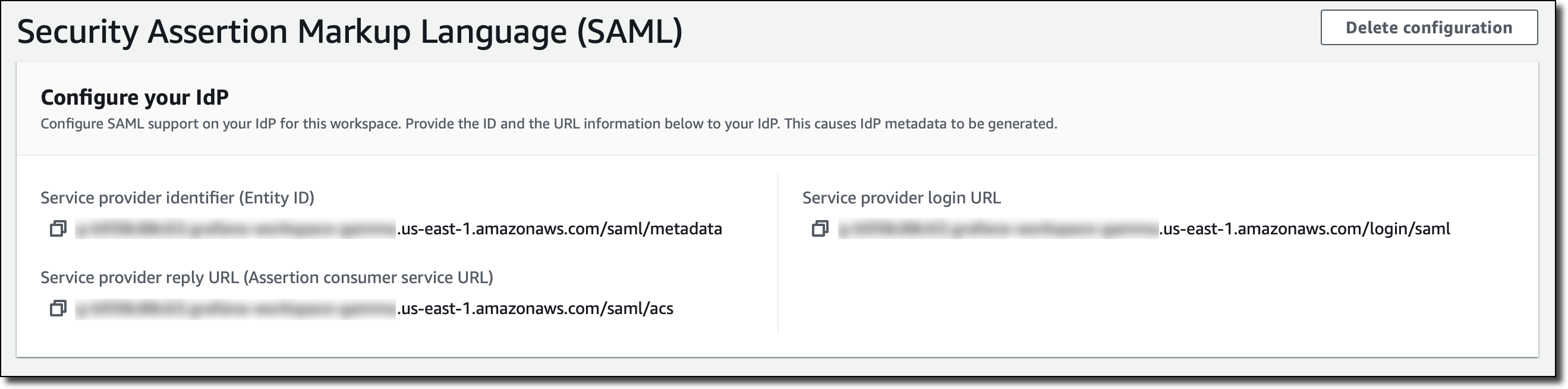
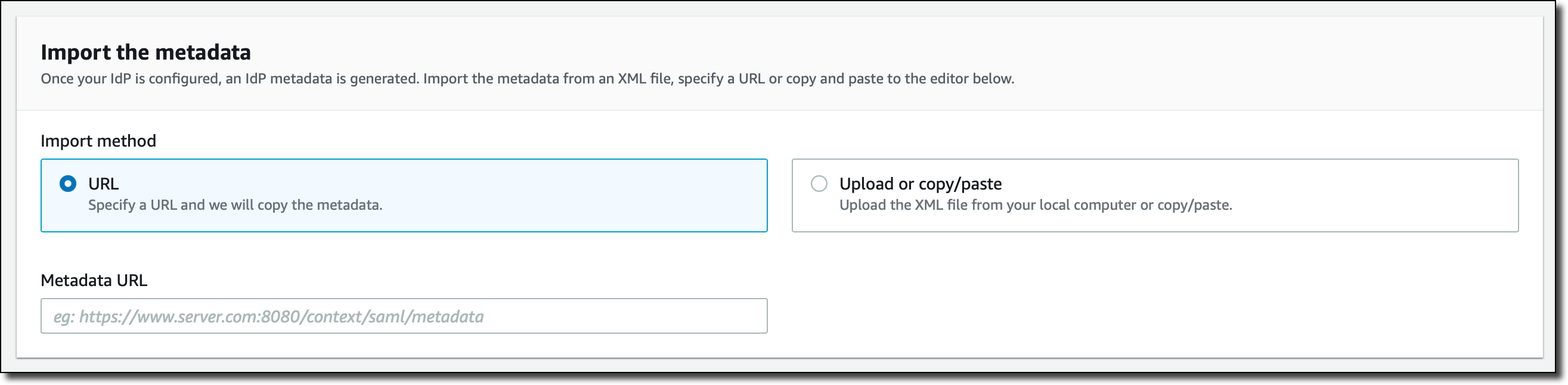
I can use AWS Single Sign-On (AWS SSO) or an external identity provider via SAML to authenticate the users of my workspace. For simplicity, I select AWS SSO. Later in the post, I’ll show how SAML authentication works. If this is your first time using AWS SSO, you can see the prerequisites (such as having AWS Organizations set up) in the documentation.
Console screenshot.

Then, I choose the Service managed permission type. In this way, Amazon Managed Grafana will automatically provision the necessary IAM permissions to access the AWS Services that I select in the next step.

Console screenshot.

In Service managed permission settings, I choose to monitor resources in my current AWS account. If you use AWS Organizations to centrally manage your AWS environment, you can use Grafana to monitor resources in your organizational units (OUs).

Console screenshot.

I can optionally select the AWS data sources that I am planning to use. This configuration creates an AWS Identity and Access Management (IAM) role that enables Amazon Managed Grafana to access those resources in my account. Later, in the Grafana console, I can set up the selected services as data sources. For now, I select Amazon CloudWatch so that I can quickly visualize CloudWatch metrics in my Grafana dashboards.

Here I also configure permissions to use Amazon Managed Service for Prometheus (AMP) as a data source and have a fully managed monitoring solution for my applications. For example, I can collect Prometheus metrics from Amazon Elastic Kubernetes Service (EKS) and Amazon Elastic Container Service (Amazon ECS) environments, using AWS Distro for OpenTelemetry or Prometheus servers as collection agents.

Console screenshot.

In this step I also select Amazon Simple Notification Service (SNS) as a notification channel. Similar to the data sources before, this option gives Amazon Managed Grafana access to SNS but does not set up the notification channel. I can do that later in the Grafana console. Specifically, this setting adds SNS publish permissions to topics that start with grafana to the IAM role created by the Amazon Managed Grafana console. If you prefer to have tighter control on permissions for SNS or any data source, you can edit the role in the IAM console or use customer-managed permissions for your workspace.

Finally, I review all the options and create the workspace.

After a few minutes, the workspace is ready, and I find the workspace URL that I can use to access the Grafana console.

Console screenshot.

I need to assign at least one user or group to the Grafana workspace to be able to access the workspace URL. I choose Assign new user or group and then select one of my AWS SSO users.

Console screenshot.

By default, the user is assigned a Viewer user type and has view-only access to the workspace. To give this user permissions to create and manage dashboards and alerts, I select the user and then choose Make admin.

Console screenshot.

Back to the workspace summary, I follow the workspace URL and sign in using my AWS SSO user credentials. I am now using the open-source version of Grafana. If you are a Grafana user, everything is familiar. For my first configurations, I will focus on AWS data sources so I choose the AWS logo on the left vertical bar.

Console screenshot.

Here, I choose CloudWatch. Permissions are already set because I selected CloudWatch in the service-managed permission settings earlier. I select the default AWS Region and add the data source. I choose the CloudWatch data source and on the Dashboards tab, I find a few dashboards for AWS services such as Amazon Elastic Compute Cloud (Amazon EC2), Amazon Elastic Block Store (EBS), AWS Lambda, Amazon Relational Database Service (RDS), and CloudWatch Logs.

Console screenshot.

I import the AWS Lambda dashboard. I can now use Grafana to monitor invocations, errors, and throttles for Lambda functions in my account. I’ll save you the screenshot because I don’t have any interesting data in this Region.

Using SAML Authentication
If I don’t have AWS SSO enabled, I can authenticate users to the Amazon Managed Grafana workspace using an external identity provider (IdP) by selecting the SAML authentication option when I create the workspace. For existing workspaces, I can choose Setup SAML configuration in the workspace summary.

First, I have to provide the workspace ID and URL information to my IdP in order to generate IdP metadata for configuring this workspace.

Console screenshot.

After my IdP is configured, I import the IdP metadata by specifying a URL or copying and pasting to the editor.

Console screenshot.

Finally, I can map user permissions in my IdP to Grafana user permissions, such as specifying which users will have Administrator, Editor, and Viewer permissions in my Amazon Managed Grafana workspace.

Console screenshot.

Availability and Pricing
Amazon Managed Grafana is available today in ten AWS Regions: US East (N. Virginia), US East (Ohio), US West (Oregon), Europe (Ireland), Europe (Frankfurt), Europe (London), Asia Pacific (Singapore), Asia Pacific (Tokyo), Asia Pacific (Sydney), and Asia Pacific (Seoul). For more information, see the AWS Regional Services List.

With Amazon Managed Grafana, you pay for the active users per workspace each month. Grafana API keys used to publish dashboards are billed as an API user license per workspace each month. You can upgrade to Grafana Enterprise to have access to enterprise plugins, support, and on-demand training directly from Grafana Labs. For more information, see the Amazon Managed Grafana pricing page.

To learn more, you are invited to this webinar on Thursday, September 9 at 9:00 am PDT / 12:00 pm EDT / 6:00 pm CEST.

Start using Amazon Managed Grafana today to visualize and analyze your operational data at any scale.

Danilo