Post Syndicated from Simone Pomata original https://aws.amazon.com/blogs/architecture/field-notes-serverless-container-based-apis-with-amazon-ecs-and-amazon-api-gateway/
A growing number of organizations choose to build their APIs with Docker containers. For hosting and exposing these container-based APIs, they need a solution which supports HTTP requests routing, autoscaling, and high availability. In some cases, user authorization is also needed.
For this purpose, many organizations are orchestrating their containerized services with Amazon Elastic Container Service (Amazon ECS) or Amazon Elastic Kubernetes Service (Amazon EKS), while hosting their containers on Amazon EC2 or AWS Fargate. Then, they can add scalability and high availability with Service Auto Scaling (in Amazon ECS) or Horizontal Pod Auto Scaler (in Amazon EKS), and they expose the services through load balancers (for example, the AWS Application Load Balancer).
When you use Amazon ECS as an orchestrator (with EC2 or Fargate launch type), you also have the option to expose your services with Amazon API Gateway and AWS Cloud Map instead of a load balancer. AWS Cloud Map is used for service discovery: no matter how Amazon ECS tasks scale, AWS Cloud Map service names would point to the right set of Amazon ECS tasks. Then, API Gateway HTTP APIs can be used to define API routes and point them to the corresponding AWS Cloud Map services.
API Gateway and AWS Cloud Map could be a good fit if you want to leverage the capabilities provided by API Gateway HTTP APIs. For example, you could import/export your API as an OpenAPI definition file. You could configure the following features, either on the whole API or – more granularly – at route level: throttling, detailed metrics, or OAuth 2.0 / OIDC user authorization. You could also deploy your API at different stages over time. Or you could easily configure CORS for your API or for any route, instead of handling OPTIONS preflight requests yourself.
If you don’t need the capabilities of API Gateway HTTP APIs or if those of Elastic Load Balancing are a better fit, then you can use the latter. For example, the capabilities of the Application Load Balancer include: content-based routing (not only by path and HTTP method, but also by HTTP header, query-string parameter, source IP, etc.), redirects, fixed responses, and others. Additionally, the Network Load Balancer provides layer 4 load balancing capabilities. Ultimately, there are overlaps and differences between the features of Elastic Load Balancing and those of API Gateway HTTP APIs: so you may want to compare them to choose the right option for your use case.
This blog post guides you through the details of the option based on API Gateway and AWS Cloud Map, and how to implement it: first you learn how the different components (Amazon ECS, AWS Cloud Map, API Gateway, etc.) work together, then you launch and test a sample container-based API.
Architecture Overview
The following diagram shows the architecture of the sample API that you are going to launch.
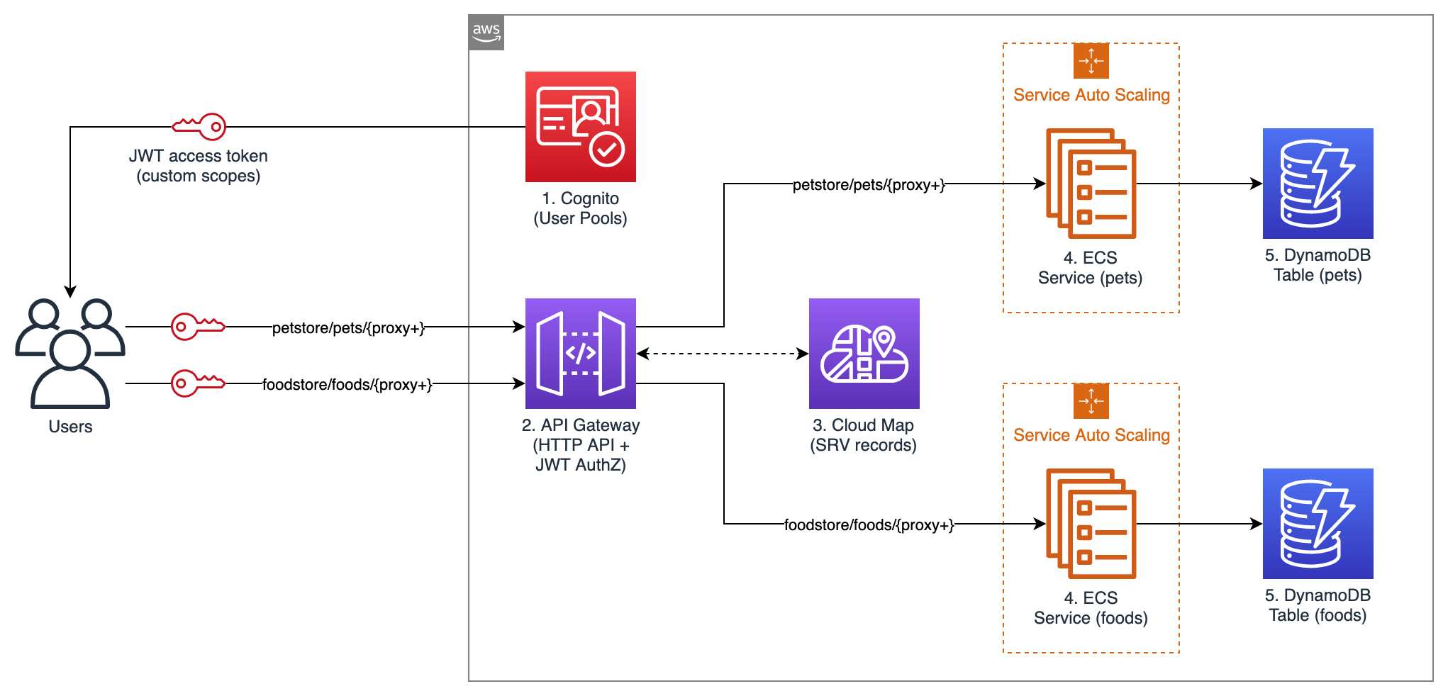
Figure 1 – Architecture Diagram
This example API exposes two services: “Food store” to PUT and GET foods, and “Pet store” to PUT and GET pets. Unauthenticated users can only GET, while authenticated users can also PUT.
The following building blocks are used:
- Amazon Cognito User Pools: for user authentication. In this example API, Amazon Cognito is used for user authentication, but you could use any other OAuth 2.0 / OIDC identity provider instead. When the user authenticates with Amazon Cognito, user pool tokens are granted, including a JWT access token that is used for authorizing requests to the container APIs.
- API Gateway HTTP APIs: for exposing the containerized services to the user. API routes and the respective integrations are defined in API Gateway. A route is the combination of a path and a method. An integration is the backend service which is invoked by that route. In this API, private integrations point to AWS Cloud Map services, which in turn resolve to private Amazon ECS services (more about AWS Cloud Map in the next paragraph). As Amazon ECS services are private resources in a Virtual Private Cloud (VPC), API Gateway uses a VPC link to connect to them in a private way. A VPC link is a set of elastic network interfaces in the VPC, assigned to and managed by API Gateway, so that API Gateway can talk privately with other resources in the VPC. This way, Amazon ECS services can be launched in private subnets and don’t need a public IP. In this sample application, JWT authorization is configured in API Gateway for PUT routes. API Gateway performs requests authorization based on validation of the JWT Token provided, and optionally, scopes in the token. This way, you don’t need additional code in your containers for authorization.
- AWS Cloud Map: for service discovery of the containerized services. API Gateway needs a way to find physical addresses of the backend services, and AWS Cloud Map provides this capability. To enable this functionality, service discovery should be configured on Amazon ECS services. Amazon ECS performs periodic health checks on tasks in Amazon ECS services and registers the healthy tasks to the respective AWS Cloud Map service. AWS Cloud Map services can then be resolved either via DNS queries or by calling the DiscoverInstances API (API Gateway uses the API). AWS Cloud Map supports different DNS record types (including A, AAAA, CNAME, and SRV); at the time, of writing, API Gateway can only retrieve SRV records from AWS Cloud Map, so SRV records are used in this sample application. With SRV records, each AWS Cloud Map service returns a combination of IP addresses and port numbers of all the healthy tasks in the service. Consider that AWS Cloud Map would perform round-robin routing (with equal weighting to the targets): for this reason, to avoid hot spots, all tasks in each service should be homogeneous (in terms of container images, vCPU, memory, and other settings).
- Amazon ECS: for hosting the containerized services. Amazon ECS is a highly scalable and high-performance container orchestrator. In this blog post, the Fargate launch type is used, so that containers are launched on the Fargate serverless compute engine, and you don’t have to provision or manage any EC2 instances. In this sample API, service auto scaling is also enabled, so that the number of containers in each service can scale up and down automatically based on % CPU usage. Containers will be launched across multiple Availability Zones in the AWS Region, to get high availability.
- Amazon DynamoDB: for persisting the data. Amazon DynamoDB is a key-value and document database that provides single-millisecond performance at any scale. In a real-world scenario, you could still use DynamoDB or another data store, such as Amazon Relational Database Service (RDS).
All the code of this blog post is publicly available in this GitHub repository. You can explore the CloudFormation template used to define the sample application as code. You can view the source code of the two containerized services: Food store repository and Pet store repository. You can also explore the code of the sample web app that you’ll use to test the API (this web app has been developed with the Amplify framework). Note that the code provided is intended for testing purposes and not for production usage.
Walkthrough
In this section, you will deploy the sample application and test it.
Prerequisites
To launch the sample API, you first need an AWS user that has access to the AWS Management Console and has the IAM permissions to launch the AWS CloudFormation stack.
Deploying the sample application
Now it’s time to launch the sample API:
- Select Launch Stack
- In the page for quick stack creation, do the following:
- Select the capability “I acknowledge that AWS CloudFormation might create IAM resources”.
- Keep the rest as default.
- Choose Create Stack.
- Wait until the status of the stack transitions to “CREATE_COMPLETE”.
Testing the sample application
In this section, you test the API from a sample web application client that I created. Open the sample web application:
- From the page of the stack, choose Outputs.
- Open the URL for the “APITestPage” output.
- On the opened page, choose Proceed.
The web page should state that you are not signed-in. In this sample API, any user can GET items, but only authenticated users can PUT items. Sign up to the sample web application:
- Choose Go To Sign In.
- Choose Create account.
- Complete the sign-up procedure (you will be asked for a valid email address, which will be registered into your Amazon Cognito User Pool).
The application should state that you are signed-in. Test the API as an authenticated user:
- Try to PUT an item. You would see that the operation succeeds. The item has been persisted by the containerized service to the DynamoDB table.

2. Try to GET the same item that you previously PUT. You would see that the same JSON is returned. This JSON is retrieved by the containerized service from the DynamoDB table.
Test the API as an unauthenticated user:
- Choose Sign Out.
- Try to GET the same item that you previously PUT. You would see that the same JSON is returned. This JSON is retrieved by the containerized service from the DynamoDB table.
- Try to PUT any item. You would get a 401 Unauthorized error from the API. This behavior is expected because only signed-in users have a JWT token, and you configured API Gateway to only authorize PUT requests that provide a valid token.

Exploring the resources of the sample application
You can also explore the resources launched as part of the CloudFormation stack. To list all of them, from the page of your CloudFormation stack, choose Resources.
To see the Amazon ECS services, go to the Amazon ECS console, choose your cluster, and you would see that 2 services are running, one for the Foodstore and another for the Petstore, as shown in the following image.
Notice that the services use the Fargate launch type, meaning that they are running on serverless compute capacity, so you don’t have to launch or maintain any EC2 instances to run them.

To see the details of a service, go to the Amazon ECS cluster page and choose a service. You land on the service page, where you can see the running tasks, the service events, and other details.
To view the service auto scaling configuration, choose Auto Scaling. You can notice that Amazon ECS is set to automatically scale the number of tasks according to the value of a metric. In this sample application, the metric is the average CPU utilization of the service (ECSServiceAverageCPUUtilization), but you could use another metric.

The scaling policy of each service uses two Amazon CloudWatch Alarms, one for scaling out and one for scaling in. An alarm is triggered when the target metric deviates from the target value, which in turn is used to trigger the scaling action. To see the alarms, go to the CloudWatch Alarms console.

To see the service discovery entries, go to the AWS Cloud Map console, choose your namespace (see the parameter “PrivateDNSNamespaceName” in the CloudFormation stack), and you would see that two services are defined. If you choose one of these services, you would see that multiple service instances are registered, each representing a single Amazon ECS task (in this sample application, each Amazon ECS task is a single container). If you choose one of these service instances, you would see the details about the task, including the private IP, the port, and the health status. API Gateway retrieves these entries to discover your services.

To see the API configuration, go to the API Gateway console and choose your API.
Then, from the left side of the screen select either Routes, Authorization, Integrations, or any other option.

Cleaning up
To clean up the resources, simply delete the CloudFormation stack that you deployed as part of this blog post.
Conclusion
You have learned how API Gateway HTTP APIs can be used together with AWS Cloud Map to expose Amazon ECS services as APIs. You have deployed a sample API that also uses Amazon Cognito for authentication and DynamoDB for data persistence.
API Gateway HTTP APIs provides a number of features that you can leverage, such as OpenAPI import/export, throttling, OAuth 2.0 / OIDC user authorization, detailed metrics, and stages deployment. That said, API Gateway is not the only way to expose your ECS services; if you don’t need the features of API Gateway HTTP APIs or if those of Elastic Load Balancing are a better fit, then you can use the latter service. The recommended approach is to compare them to choose the most suitable for your use case.