All posts by Kalyan Janaki

Simplified management of Amazon MSK with natural language using Kiro CLI and Amazon MSK MCP Server

Post Syndicated from Kalyan Janaki original https://aws.amazon.com/blogs/big-data/simplified-management-of-amazon-msk-with-natural-language-using-kiro-cli-and-amazon-msk-mcp-server/

Managing and scaling data streams efficiently is a cornerstone of success for many organizations. Apache Kafka is a leading platform for real-time data streaming, offering unmatched scalability and reliability. However, setting up and scaling Kafka clusters can be challenging, requiring significant time, expertise, and resources. Amazon Managed Streaming for Apache Kafka (MSK) helps you build and run production applications on Apache Kafka without needing Kafka infrastructure management expertise or having to deal with the complex overhead associated with setting up and running Apache Kafka on your own.

Amazon MSK Provisioned supports both Standard brokers and Express brokers. Express brokers are designed for higher throughput, faster scalability, and lower operational overhead, while Standard brokers offer more granular control and configuration flexibility. While Amazon MSK significantly reduces cluster management overhead, teams still perform routine tasks such as topic management, partition management, and implementing specific configurations to meet their business requirements.

To further simplify these day-to-day operations, you can use Kiro Command Line Interface (CLI) along with the MSK Model Context Protocol (MCP) server for a more intuitive approach to cluster management. These tools enable teams to perform administrative tasks and operational activities using natural language commands. Whether you’re managing topics, monitoring cluster health, or implementing specific configurations, the ability to use plain English commands makes these tasks more accessible to both experienced administrators and developers new to Kafka.

In this post, we demonstrate how Kiro CLI and the MSK MCP server can streamline your Kafka management. Through practical examples and demonstrations, we show you how to use these tools to perform common administrative tasks efficiently while maintaining robust security and reliability.

Understanding the Model Context Protocol advantage

The MCP is an emerging open standard that defines how artificial intelligence (AI) agents can securely access and interact with external tools, data sources, and services. Rather than requiring developers learn intricate API syntax across multiple services, MCP enables AI assistants to understand your environment contextually and provide intelligent guidance. A Kiro CLI agent is an AI-powered assistant in the command-line interface that understands your code and environment to execute tasks, generate code, and automate workflows through natural language interactions. Together, Kiro CLI and the Model Context Protocol (MCP) enable teams to manage their MSK clusters using natural language, making cluster administration more intuitive and accessible.

The Amazon MSK MCP Server provides essential cluster administration capabilities including describing clusters, updating configurations, and monitoring broker health status. By combining these capabilities with Kiro CLI’s ability to interact with native Kafka command-line tools, teams gain comprehensive visibility into their Apache Kafka environment. Through this unified approach, users can manage both control plane operations via the MCP server and data plane operations, like topic management, through Kiro CLI’s interface with Kafka tools. This integration enables teams to monitor, manage, and optimize their clusters through conversational interactions while maintaining enterprise-grade security through AWS Identity and Access Management (IAM) and fine-grained access controls.

Prerequisites

For this walkthrough, you should have the following prerequisites:

Configure Kiro CLI with Amazon MSK MCP server

Installation and configuration
The following section covers the steps required to install and configure Amazon MSK MCP server.

Install required dependencies
Complete the following steps to install required dependencies:

  1. Install the uv package manager if you haven’t already:
# macOS/Linux
curl -LsSf  | sh

# Windows
powershell -c "irm  | iex“
Install Python 3.10 or newer:
uv python install 3.10

Configure the MCP server
Complete the following instructions to set up Kiro CLI on your host machine and access the Amazon MSK MCP server. Configure the Amazon MSK MCP server in your Kiro CLI configuration. Edit the MCP configuration file at ~/.aws/.kiro/mcp.json:

MacOS Installation

For MacOS, the mcp.json file should be as follows:

"awslabs.aws-msk-mcp-server": {
"command": "uvx",
"args": [
"awslabs.aws-msk-mcp-server@latest",
"—allow-writes“
],
"env": {
"FASTMCP_LOG_LEVEL": "ERROR"
},
"disabled": false,
"autoApprove": []
}

Windows Installation
For Windows users, the MCP server configuration format is slightly different:

{
"mcpServers": {
"awslabs.aws-msk-mcp-server": {
"disabled": false,
"timeout": 60,
"type": "stdio",
"command": "uv",
"args": [
"tool",
"run",
"—from",
"awslabs.aws-msk-mcp-server@latest",
"awslabs.aws-msk-mcp-server.exe"
],
"env": {
"FASTMCP_LOG_LEVEL": "ERROR",
"AWS_PROFILE": "your-aws-profile",
"AWS_REGION": "us-east-1"
}
}
}
}

For further details on installation, refer to the Installation section in the Amazon MSK MCP server README.md.

  1. Start Kiro CLI to verify the MCP server is properly configured using the following command:
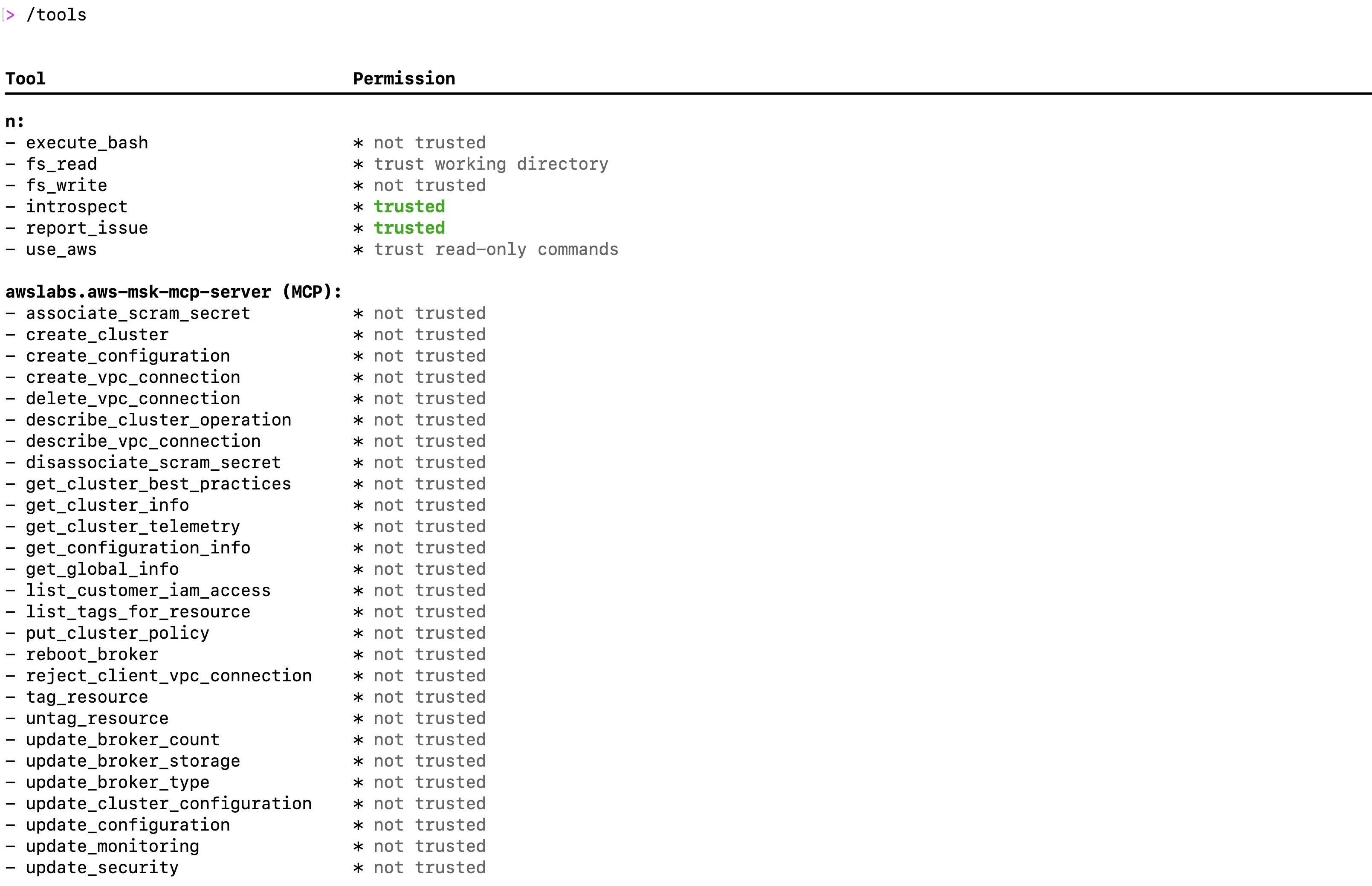
 kiro-cli
  2. Once logged into Kiro CLI, type the following command to check all the MSK mcp server tools are available as shown in the following screenshot: /tools

Installing and configuring Kafka CLI

To perform data plane operations on your Amazon MSK cluster, you need the Kafka command-line tools configured correctly. In the following video demonstration, we show how developers and administrators can use Kiro CLI to streamline the installation and configuration of Kafka command-line tools, enabling seamless interaction with their MSK cluster through natural language commands.

Evaluate cluster best practices

Maintaining a healthy and efficient Apache Kafka cluster requires adherence to established best practices, from proper replication factors to optimal resource utilization. Amazon MSK implements many of these best practices by default, but ongoing monitoring and adjustment are essential for production workloads. In the following demonstration, we show how Kiro CLI can help you evaluate your cluster’s configuration against recommended best practices, identify potential issues, and receive actionable recommendations for optimization. Watch the following demo video as we use natural language queries to assess MSK clusters against AWS recommended best practices and identify topics with replication factors not configured according to best practices and fix them.

Responding to health notifications: Optimizing topic configurations for high availability

Amazon MSK’s health notifications serve as crucial alerts to maintain optimal cluster performance and reliability. For customers using MSK Provisioned with Standard brokers, they may receive notifications about critical configuration parameters such as MinISR and replication factor settings that could impact application resilience. In this section, we demonstrate how Kiro CLI can help you quickly respond to a health notification regarding MinISR (Minimum In-Sync Replicas) and replication factor configurations. Watch as we use natural language commands to identify topics with suboptimal settings, understand their current configurations, and implement the recommended changes to confirm high availability during infrastructure maintenance or recovery events. This real-world scenario showcases how Kiro CLI simplifies the process of maintaining robust Kafka operations while following AWS best practices.

Managing cluster-level configurations: Streamlining parameter updates with natural language

Apache Kafka clusters often require configuration adjustments to meet specific security requirements and use cases. While Amazon MSK provides default configurations, there are situations when you need to customize security parameters like allow.everyone.if.no.acl.found to implement proper access controls and strengthen your cluster’s security posture. In this demonstration, we show how Kiro CLI with MSK MCP server simplifies the process of updating cluster-level configurations.

Instead of opening multiple CLI commands or console screens, you see how natural language instructions can be used to understand current security settings, evaluate the impact of changes, and implement configuration updates seamlessly across your MSK cluster. By setting allow.everyone.if.no.acl.found to false, we confirm that explicit ACL permissions are required for all operations, enhancing the security of your Kafka deployment.

Conclusion

In this post, we demonstrated how Kiro CLI and MSK MCP server make Apache Kafka cluster management more accessible through natural language commands. By transforming complex Kafka operations into simple conversational interactions, these tools enable both experienced administrators and newcomers to efficiently manage their MSK clusters. From routine tasks to addressing configuration challenges, this approach reduces operational complexity and allows teams to focus more on developing innovative streaming applications.


About the authors

Kalyan Janaki is Senior Big Data & Analytics Specialist with Amazon Web Services. He helps customers architect and build highly scalable, performant, and secure cloud-based solutions on AWS.

Aarjvi Desai is a Technical Account Manager at Amazon Web Services, based in San Francisco Bay Area, where she helps customers solve cloud challenges and build scalable, reliable solutions. Her areas of focus include cloud technologies, architecture best practices, and operational excellence.

Sandhya Khanderia is Sr. Technical Account Manager and Data analytics specialist. She works with AWS customers and provides ongoing support and technical guidance to help plan and build solutions using best practices and proactively keep customers’ AWS environments operationally healthy.

Ankit Mishra is a Senior Solutions Architect at Amazon Web Services, where he supports healthcare and life sciences customers around the globe. He is passionate about helping organizations design and build secure, scalable, reliable, and cost-effective cloud solutions. Outside of work, Ankit enjoysspending quality time with his young daughters. Feel free to connect with him on LinkedIn.

Unify streaming and analytical data with Amazon Data Firehose and Amazon SageMaker Lakehouse

Post Syndicated from Kalyan Janaki original https://aws.amazon.com/blogs/big-data/unify-streaming-and-analytical-data-with-amazon-data-firehose-and-amazon-sagemaker-lakehouse/

Organizations are increasingly required to derive real-time insights from their data while maintaining the ability to perform analytics. This dual requirement presents a significant challenge: how to effectively bridge the gap between streaming data and analytical workloads without creating complex, hard-to-maintain data pipelines. In this post, we demonstrate how to simplify this process using Amazon Data Firehose (Firehose) to deliver streaming data directly to Apache Iceberg tables in Amazon SageMaker Lakehouse, creating a streamlined pipeline that reduces complexity and maintenance overhead.

Streaming data empowers AI and machine learning (ML) models to learn and adapt in real time, which is crucial for applications that require immediate insights or dynamic responses to changing conditions. This creates new opportunities for business agility and innovation. Key use cases include predicting equipment failures based on sensor data, monitoring supply chain processes in real time, and enabling AI applications to respond dynamically to changing conditions. Real-time streaming data helps customers make quick decisions, fundamentally changing how businesses compete in real-time markets.

Amazon Data Firehose seamlessly acquires, transforms, and delivers data streams to lakehouses, data lakes, data warehouses, and analytics services, with automatic scaling and delivery within seconds. For analytical workloads, a lakehouse architecture has emerged as an effective solution, combining the best elements of data lakes and data warehouses. Apache Iceberg, an open table format, enables this transformation by providing transactional guarantees, schema evolution, and efficient metadata handling that were previously only available in traditional data warehouses. SageMaker Lakehouse unifies your data across Amazon Simple Storage Service (Amazon S3) data lakes, Amazon Redshift data warehouses, and other sources, and gives you the flexibility to access your data in-place with Iceberg-compatible tools and engines. By using SageMaker Lakehouse, organizations can harness the power of Iceberg while benefiting from the scalability and flexibility of a cloud-based solution. This integration removes the traditional barriers between data storage and ML processes, so data workers can work directly with Iceberg tables in their preferred tools and notebooks.

In this post, we show you how to create Iceberg tables in Amazon SageMaker Unified Studio and stream data to these tables using Firehose. With this integration, data engineers, analysts, and data scientists can seamlessly collaborate and build end-to-end analytics and ML workflows using SageMaker Unified Studio, removing traditional silos and accelerating the journey from data ingestion to production ML models.

Solution overview

The following diagram illustrates the architecture of how Firehose can deliver real-time data to SageMaker Lakehouse.

This post includes an AWS CloudFormation template to set up supporting resources so Firehose can deliver streaming data to Iceberg tables. You can review and customize it to suit your needs. The template performs the following operations:

Prerequisites

For this walkthrough, you should have the following prerequisites:

After you create the prerequisites, verify you can log in to SageMaker Unified Studio and the project is created successfully. Every project created in SageMaker Unified Studio gets a project location and project IAM role, as highlighted in the following screenshot.

Create an Iceberg table

For this solution, we use Amazon Athena as the engine for our query editor. Complete the following steps to create your Iceberg table:

  1. In SageMaker Unified Studio, on the Build menu, choose Query Editor.

  1. Choose Athena as the engine for query editor and choose the AWS Glue database created for the project.

  1. Use the following SQL statement to create the Iceberg table. Make sure to provide your project AWS Glue database and project Amazon S3 location (can be found on the project overview page):
CREATE TABLE firehose_events (
type struct<device: string, event: string, action: string>,
customer_id string,
event_timestamp timestamp,
region string)
LOCATION '<PROJECT_S3_LOCATION>/iceberg/events'
TBLPROPERTIES (
'table_type'='iceberg',
'write_compression'='zstd'
);

Deploy the supporting resources

The next step is to deploy the required resources into your AWS environment by using a CloudFormation template. Complete the following steps:

  1. Choose Launch Stack.
  2. Choose Next.
  3. Leave the stack name as firehose-lakehouse.
  4. Provide the user name and password that you want to use for accessing the Amazon Kinesis Data Generator application.
  5. For DatabaseName, enter the AWS Glue database name.
  6. For ProjectBucketName, enter the project bucket name (located on the SageMaker Unified Studio project details page).
  7. For TableName, enter the table name created in SageMaker Unified Studio.
  8. Choose Next.

  1. Select I acknowledge that AWS CloudFormation might create IAM resources and choose Next.

  1. Complete the stack.

Create a Firehose stream

Complete the following steps to create a Firehose stream to deliver data to Amazon S3:

  1. On the Firehose console, choose Create Firehose stream.

  1. For Source, choose Direct PUT.
  2. For Destination, choose Apache Iceberg Tables.

This example chooses Direct PUT as the source, but you can apply the same steps for other Firehose sources, such as Amazon Kinesis Data Streams and Amazon Managed Streaming for Apache Kafka (Amazon MSK).

  1. For Firehose stream name, enter firehose-iceberg-events.

  1. Collect the database name and table name from the SageMaker Unified Studio project to use in the next step.

  1. In the Destination settings section, enable Inline parsing for routing information and provide the database name and table name from the previous step.

Make sure you enclose the database and table names in double quotes if you want to deliver data to a single database and table. Amazon Data Firehose can also route records to different tables based on the content of the record. For more information, refer to Route incoming records to different Iceberg tables.

  1. Under Buffer hints, reduce the buffer size to 1 MiB and the buffer interval to 60 seconds. You can fine-tune these settings based on your use case latency needs.

  1. In the Backup settings section, enter the S3 bucket created by the CloudFormation template (s3://firehose-demo-iceberg-<account_id>-<region>) and the error output prefix (error/events-1/).

  1. In the Advanced settings section, enable Amazon CloudWatch error logging to troubleshoot any failures, and in for Existing IAM roles, choose the role that starts with Firehose-Iceberg-Stack-FirehoseIamRole-*, created by the CloudFormation template.
  2. Choose Create Firehose stream.

Generate streaming data

Use the Amazon Kinesis Data Generator to publish data records into your Firehose stream:

  1. On the AWS CloudFormation console, choose Stacks in the navigation pane and open your stack.
  2. Select the nested stack for the generator, and go to the Outputs tab.
  3. Choose the Amazon Kinesis Data Generator URL.

  1. Enter the credentials that you defined when deploying the CloudFormation stack.

  1. Choose the AWS Region where you deployed the CloudFormation stack and choose your Firehose stream.
  2. For the template, replace the default values with the following code:
{
"type": {
"device": "{{random.arrayElement(["mobile", "desktop", "tablet"])}}",
"event": "{{random.arrayElement(["firehose_events_1", "firehose_events_2"])}}",
"action": "update"
},
"customer_id": "{{random.number({ "min": 1, "max": 1500})}}",
"event_timestamp": "{{date.now("YYYY-MM-DDTHH:mm:ss.SSS")}}",
"region": "{{random.arrayElement(["pdx", "nyc"])}}"
}
  1. Before sending data, choose Test template to see an example payload.
  2. Choose Send data.

You can monitor the progress of the data stream.

Query the table in SageMaker Unified Studio

Now that Firehose is delivering data to SageMaker Lakehouse, you can perform analytics on that data in SageMaker Unified Studio using different AWS analytics services.

Clean up

It’s generally a good practice to clean up the resources created as part of this post to avoid additional cost. Complete the following steps:

  1. On the AWS CloudFormation console, choose Stacks in the navigation pane.
  2. Select the stack firehose-lakehouse* and on the Actions menu, choose Delete Stack.
  3. In SageMaker Unified Studio, delete the domain created for this post.

Conclusion

Streaming data allows models to make predictions or decisions based on the latest information, which is crucial for time-sensitive applications. By incorporating real-time data, models can make more accurate predictions and decisions. Streaming data can help organizations avoid the costs associated with storing and processing large datasets, because it focuses on the most relevant information. Amazon Data Firehose makes it straightforward to bring real-time streaming data to data lakes in Iceberg format and unifying it with other data assets in SageMaker Lakehouse, making streaming data accessible by various analytics and AI services in SageMaker Unified Studio to deliver real-time insights. Try out the solution for your own use case, and share your feedback and questions in the comments.


About the Authors

Kalyan Janaki is Senior Big Data & Analytics Specialist with Amazon Web Services. He helps customers architect and build highly scalable, performant, and secure cloud-based solutions on AWS.

Phaneendra Vuliyaragoli is a Product Management Lead for Amazon Data Firehose at AWS. In this role, Phaneendra leads the product and go-to-market strategy for Amazon Data Firehose.

Maria Ho is a Product Marketing Manager for Streaming and Messaging services at AWS. She works with services including Amazon Managed Streaming for Apache Kafka (Amazon MSK), Amazon Managed Service for Apache Flink, Amazon Data Firehose, Amazon Kinesis Data Streams, Amazon MQ, Amazon Simple Queue Service (Amazon SQS), and Amazon Simple Notification Services (Amazon SNS).

Fitch Group achieves multi-Region resiliency for mission-critical Kafka infrastructure with Amazon MSK Replicator

Post Syndicated from Kalyan Janaki original https://aws.amazon.com/blogs/big-data/fitch-group-achieves-multi-region-resiliency-for-mission-critical-kafka-infrastructure-with-amazon-msk-replicator/

Real-time data streaming and event processing are critical components of modern distributed systems architectures. Apache Kafka has emerged as a leading platform for building real-time data pipelines and enabling asynchronous communication between microservices and applications. However, running and managing Kafka clusters at scale can be challenging, requiring specialized expertise and significant operational overhead.

Amazon Managed Streaming for Apache Kafka (Amazon MSK) is a fully managed service that allows you to build and run production Kafka applications. With Amazon MSK, you can rely on AWS to handle the heavy lifting of provisioning and managing Kafka clusters, while you focus on building innovative applications and real-time data processing pipelines.

In this post, we explore how Fitch Group, one of the top credit rating companies, used Amazon MSK and Amazon MSK Replicator to achieve multi-Region resiliency for their mission-critical Kafka infrastructure.

About Fitch Group and their need for multi-region resiliency

As a leading global financial information services provider, Fitch Group delivers vital credit and risk insights, robust data, and dynamic tools to champion more efficient, transparent financial markets. With employees in over 30 countries, Fitch Group’s culture of credibility, independence, and transparency is embedded throughout its structure, which includes Fitch Ratings, one of the world’s top three credit ratings agencies, and Fitch Solutions, a leading provider of insights, data, and analytics.

To stay competitive and efficient in the fast-paced financial industry, Fitch Group strategically adopted an event-driven microservices architecture. At the heart of this ecosystem lies Kafka, specifically Amazon MSK, which serves as the backbone for their data integration systems.

Fitch Group uses Kafka to enable applications to send ratings-related business events, facilitating automation within their ratings workflow systems and providing real-time or near real-time processing. This architectural choice has significantly reduced the time to market for end-user-facing systems like Fitch Ratings Pro and Fitch Group Ratings websites. Moreover, Kafka’s robust capabilities allow for seamless aggregation and distribution of data from many disparate systems through their data platform, enhancing data consistency, reliability, and accessibility across the organization.

Given the critical role that Kafka plays in Fitch Group architecture, providing robust disaster recovery (DR) mechanisms became paramount. Any disruption to their Kafka infrastructure could have significant repercussions on their ratings workflow automation, real-time processing, and end-user-facing systems, potentially exposing Fitch Group to regulatory, financial, and reputational risks.

To achieve the desired levels of resiliency, Fitch Group had the following key requirements:

  • Multi-Region deployment – Deploy MSK clusters across multiple AWS Regions to provide business continuity and maintain service availability during Regional or service events
  • Automated replication – Replicate Kafka data across Regions in near real time with minimal latency and data loss
  • Consistent topic namespaces – Maintain the same Kafka topic names and structures across source and destination clusters to minimize application changes
  • Rapid recovery – In the event of a failover, enable applications to seamlessly start consuming from the replicated cluster with minimal Recovery Time Objective (RTO) and Recovery Point Objective (RPO)

Solution overview

Fitch Group chose to implement their multi-Region Kafka deployment using Amazon MSK and MSK Replicator. MSK Replicator is a fully managed replication service that enables continuous, automated data replication between MSK clusters within the same Region or across different Regions. It supports replicating data between clusters with different configurations, including varying broker counts, storage volumes, and Kafka versions. Here’s how Fitch Group used MSK Replicator to achieve their multi-Region resiliency goals:

  • Deployed MSK clusters in two separate Regions, with the primary cluster in the main Region and the secondary cluster in a different Region for disaster recovery
  • Configured MSK Replicator to continuously replicate data from the primary cluster to the secondary cluster, maintaining the same topic names and structures across both clusters
  • Implemented application failover logic to automatically switch to consuming from the secondary cluster in case of a primary cluster unavailability, with minimal recovery time and data loss

The following diagram illustrates this architecture

Benefits achieved

By implementing Amazon MSK and MSK Replicator, Fitch Group realized several key benefits:

  • Enhanced disaster recovery – The multi-Region deployment provides business continuity even in the face of Regional or service events.
  • Simplified operations – The managed capability of MSK Replicator offloads the operational complexity of self-managing custom replication solutions, reducing the burden on Fitch Group’s IT team
  • Scalability – The solution can scale to handle varying data loads, making sure that DR capabilities grow alongside business needs
  • Minimal application changes – MSK Replicator supports replicating topics with the same name, which eliminates the need for consumer application modifications, reducing development effort and potential errors
  • Seamless failover and failback – Bidirectional replication capabilities enable quick switching of operations to the standby Region with minimal disruption, and straightforward reversion after the primary Region is restored
  • Improved testing capabilities – The setup facilitates regular DR exercises without impacting production systems, allowing Fitch Group to validate their DR plans consistently

Conclusion

By using Amazon MSK and MSK Replicator, Fitch Group has successfully implemented a highly resilient and scalable Kafka infrastructure that meets their stringent business continuity and disaster recovery requirements. This multi-Region deployment enables them to process mission-critical financial data at scale while providing minimal downtime and data loss in the event of service events or disasters. As Fitch Group continues to innovate and grow, their robust Kafka infrastructure provides a solid foundation for future expansion and the development of new data-driven services, ultimately enhancing their ability to deliver timely and accurate financial insights to their clients.


About the authors

Kalyan Janaki is Senior Big Data & Analytics Specialist with Amazon Web Services. He helps customers architect and build highly scalable, performant, and secure cloud-based solutions on AWS.

Venu Nemallikanti is the Enterprise Architect and Lead for Event Streaming at Fitch Group, a globally recognized financial information services provider operating in over 30 countries. His primary responsibilities include overseeing the architecture and implementation of event streaming solutions, ensuring the seamless integration and performance of systems that deliver credit ratings, research, data, and analytics to a worldwide clientele.

Chaitanya Shah is a Principal Technical Account Manager with AWS, based out of New York. He loves to code and actively contributes to the AWS solutions labs to help customers solve complex problems. He provides guidance to AWS customers on best practices for their Cloud migrations. He is also specialized in AWS data transfer and the data and analytics domain.

Oleg Chugaev is a Principal Solutions Architect and Serverless evangelist with 20+ years in IT, holding multiple AWS certifications. At AWS, he drives customers through their cloud transformation journeys by converting complex challenges into actionable roadmaps for both technical and business audiences.

Introducing support for Apache Kafka on Raft mode (KRaft) with Amazon MSK clusters

Post Syndicated from Kalyan Janaki original https://aws.amazon.com/blogs/big-data/introducing-support-for-apache-kafka-on-raft-mode-kraft-with-amazon-msk-clusters/

Organizations are adopting Apache Kafka and Amazon Managed Streaming for Apache Kafka (Amazon MSK) to capture and analyze data in real time. Amazon MSK helps you build and run production applications on Apache Kafka without needing Kafka infrastructure management expertise or having to deal with the complex overhead associated with setting up and running Apache Kafka on your own. Since its inception, Apache Kafka has depended on Apache Zookeeper for storing and replicating the metadata of Kafka brokers and topics. Starting from Apache Kafka version 3.3, the Kafka community has adopted KRaft (Apache Kafka on Raft), a consensus protocol, to replace Kafka’s dependency on ZooKeeper for metadata management. In the future, the Apache Kafka community plans to remove the ZooKeeper mode entirely.

Today, we’re excited to launch support for KRaft on new clusters on Amazon MSK starting from version 3.7. In this post, we walk you through some details around how KRaft mode helps over the ZooKeeper approach. We also guide you through the process of creating MSK clusters with KRaft mode and how to connect your application to MSK clusters with KRaft mode.

Why was ZooKeeper replaced with KRaft mode

The traditional Kafka architecture relies on ZooKeeper as the authoritative source for cluster metadata. Read and write access to metadata in ZooKeeper is funneled through a single Kafka controller. For clusters with a large number of partitions, this architecture can create a bottleneck during scenarios such as an uncontrolled broker shutdown or controller failover, due to a single-controller approach.

KRaft mode addresses these limitations by managing metadata within the Kafka cluster itself. Instead of relying on a separate ZooKeeper cluster, KRaft mode stores and replicates the cluster metadata across multiple Kafka controller nodes, forming a metadata quorum. The KRaft controller nodes comprise a Raft quorum that manages the Kafka metadata log. By distributing the metadata management responsibilities across multiple controller nodes, KRaft mode improves recovery time for scenarios such as uncontrolled broker shutdown or controller failover. For more details on KRaft mode and its implementation, refer to the KIP-500: Replace ZooKeeper with a Self-Managed Metadata Quorum.

The following figure compares the three-node MSK cluster architecture with ZooKeeper vs. KRaft mode.

Amazon MSK with KRaft mode

Until now, Amazon MSK has supported Kafka clusters that rely on ZooKeeper for metadata management. One of the key benefits of Amazon MSK is that it handles the complexity of setting up and managing the ZooKeeper cluster at no additional cost. Many organizations use Amazon MSK to run large, business-critical streaming applications that require splitting their traffic across thousands of partitions. As the size of a Kafka cluster grows, the amount of metadata generated within the cluster increases proportionally to the number of partitions.

Two key properties govern the number of partitions a Kafka cluster can support: the per-node partition count limit and the cluster-wide partition limit. As mentioned earlier, the metadata management system based on ZooKeeper imposed a bottleneck on the cluster-wide partition limitation in Apache Kafka. However, with the introduction of KRaft mode in Amazon MSK starting with version 3.7, Amazon MSK now enables the creation of clusters with up to 60 brokers vs. the default quota of 30 brokers in ZooKeeper mode. Kafka’s scalability still fundamentally relies on expanding the cluster by adding more nodes to increase overall capacity. Consequently, the cluster-wide partition limit continues to define the upper bounds of scalability within the Kafka system, because it determines the maximum number of partitions that can be distributed across the available nodes. Amazon MSK manages the KRaft controller nodes at no additional cost.

Create and access an MSK cluster with KRaft mode

Complete the following steps to configure an MSK cluster with KRaft mode:

  1. On the Amazon MSK console, choose Clusters in the navigation pane.
  2. Choose Create cluster.
  3. For Cluster creation method, select Custom create.
  4. For Cluster name, enter a name.
  5. For Cluster type¸ select Provisioned.
  6. For Apache Kafka version, choose 3.7.x.
  7. For Metadata mode, select KRaft.
  8. Leave the other settings as default and choose Create cluster.

When the cluster creation is successful, you can navigate to the cluster and choose View client integration information, which will provide details about the cluster bootstrap servers.

Adapt your client applications and tools for accessing MSK clusters with KRaft mode

With the adoption of KRaft mode in Amazon MSK, customers using client applications and tools that connect to ZooKeeper to interact with MSK clusters will need to update them to reflect the removal of ZooKeeper from the architecture. Starting with version 1.0, Kafka introduced the ability for admin tools to use the bootstrap servers (brokers) as input parameters instead of a ZooKeeper connection string, and started deprecating ZooKeeper connection strings starting with version 2.5. This change was part of the efforts to decouple Kafka from ZooKeeper and pave the way for its eventual replacement with KRaft mode for metadata management. Instead of specifying the ZooKeeper connection string, clients will need to use the bootstrap.servers configuration option to connect directly to the Kafka brokers. The following table summarizes these changes.

. With Zookeeper With KRaft
Client and Services bootstrap.servers=broker:<port> or zookeeper.connect=zookeeper:2181 (deprecated) bootstrap.servers=broker:<port>
Admin Tools kafka-topics --zookeeper zookeeper:2181 (deprecated) or kafka-topics —bootstrap-server broker:<port> … —command-config kafka-topics —bootstrap-server broker:<port> … —command-config

Summary

In this post, we discussed how Amazon MSK has launched support for KRaft mode for metadata management. We also described how KRaft works and how it’s different from ZooKeeper.

To get started, create a new cluster with KRaft mode using the AWS Management Console, and refer to the Amazon MSK Developer Guide for more information.


About the author

Kalyan Janaki is Senior Big Data & Analytics Specialist with Amazon Web Services. He helps customers architect and build highly scalable, performant, and secure cloud-based solutions on AWS.

Build an end-to-end change data capture with Amazon MSK Connect and AWS Glue Schema Registry

Post Syndicated from Kalyan Janaki original https://aws.amazon.com/blogs/big-data/build-an-end-to-end-change-data-capture-with-amazon-msk-connect-and-aws-glue-schema-registry/

The value of data is time sensitive. Real-time processing makes data-driven decisions accurate and actionable in seconds or minutes instead of hours or days. Change data capture (CDC) refers to the process of identifying and capturing changes made to data in a database and then delivering those changes in real time to a downstream system. Capturing every change from transactions in a source database and moving them to the target in real time keeps the systems synchronized, and helps with real-time analytics use cases and zero-downtime database migrations. The following are a few benefits of CDC:

  • It eliminates the need for bulk load updating and inconvenient batch windows by enabling incremental loading or real-time streaming of data changes into your target repository.
  • It ensures that data in multiple systems stays in sync. This is especially important if you’re making time-sensitive decisions in a high-velocity data environment.

Kafka Connect is an open-source component of Apache Kafka that works as a centralized data hub for simple data integration between databases, key-value stores, search indexes, and file systems. The AWS Glue Schema Registry allows you to centrally discover, control, and evolve data stream schemas. Kafka Connect and Schema Registry integrate to capture schema information from connectors. Kafka Connect provides a mechanism for converting data from the internal data types used by Kafka Connect to data types represented as Avro, Protobuf, or JSON Schema. AvroConverter, ProtobufConverter, and JsonSchemaConverter automatically register schemas generated by Kafka connectors (source) that produce data to Kafka. Connectors (sink) that consume data from Kafka receive schema information in addition to the data for each message. This allows sink connectors to know the structure of the data to provide capabilities like maintaining a database table schema in a data catalog.

The post demonstrates how to build an end-to-end CDC using Amazon MSK Connect, an AWS managed service to deploy and run Kafka Connect applications and AWS Glue Schema Registry, which allows you to centrally discover, control, and evolve data stream schemas.

Solution overview

On the producer side, for this example we choose a MySQL-compatible Amazon Aurora database as the data source, and we have a Debezium MySQL connector to perform CDC. The Debezium connector continuously monitors the databases and pushes row-level changes to a Kafka topic. The connector fetches the schema from the database to serialize the records into a binary form. If the schema doesn’t already exist in the registry, the schema will be registered. If the schema exists but the serializer is using a new version, the schema registry checks the compatibility mode of the schema before updating the schema. In this solution, we use backward compatibility mode. The schema registry returns an error if a new version of the schema is not backward compatible, and we can configure Kafka Connect to send incompatible messages to the dead-letter queue.

On the consumer side, we use an Amazon Simple Storage Service (Amazon S3) sink connector to deserialize the record and store changes to Amazon S3. We build and deploy the Debezium connector and the Amazon S3 sink using MSK Connect.

Example schema

For this post, we use the following schema as the first version of the table:

{ 
    “Database Name”: “sampledatabase”, 
    “Table Name”: “movies”, 
    “Fields”: [
         { 
            “name”: “movie_id”, 
            “type”: “INTEGER” 
         },
         { 
            “name”: “title”, 
            “type”: “STRING” 
         },
         { 
            “name”: “release_year”,
            “type”: “INTEGER” 
         }
     ] 
}

Prerequisites

Before configuring the MSK producer and consumer connectors, we need to first set up a data source, MSK cluster, and new schema registry. We provide an AWS CloudFormation template to generate the supporting resources needed for the solution:

  • A MySQL-compatible Aurora database as the data source. To perform CDC, we turn on binary logging in the DB cluster parameter group.
  • An MSK cluster. To simplify the network connection, we use the same VPC for the Aurora database and the MSK cluster.
  • Two schema registries to handle schemas for message key and message value.
  • One S3 bucket as the data sink.
  • MSK Connect plugins and worker configuration needed for this demo.
  • One Amazon Elastic Compute Cloud (Amazon EC2) instance to run database commands.

To set up resources in your AWS account, complete the following steps in an AWS Region that supports Amazon MSK, MSK Connect, and the AWS Glue Schema Registry:

  1. Choose Launch Stack:
  2. Choose Next.
  3. For Stack name, enter suitable name.
  4. For Database Password, enter the password you want for the database user.
  5. Keep other values as default.
  6. Choose Next.
  7. On the next page, choose Next.
  8. Review the details on the final page and select I acknowledge that AWS CloudFormation might create IAM resources.
  9. Choose Create stack.

Custom plugin for the source and destination connector

A custom plugin is a set of JAR files that contain the implementation of one or more connectors, transforms, or converters. Amazon MSK will install the plugin on the workers of the MSK Connect cluster where the connector is running. As part of this demo, for the source connector we use open-source Debezium MySQL connector JARs, and for the destination connector we use the Confluent community licensed Amazon S3 sink connector JARs. Both the plugins are also added with libraries for Avro Serializers and Deserializers of the AWS Glue Schema Registry. These custom plugins are already created as part of the CloudFormation template deployed in the previous step.

Use the AWS Glue Schema Registry with the Debezium connector on MSK Connect as the MSK producer

We first deploy the source connector using the Debezium MySQL plugin to stream data from an Amazon Aurora MySQL-Compatible Edition database to Amazon MSK. Complete the following steps:

  1. On the Amazon MSK console, in the navigation pane, under MSK Connect, choose Connectors.
  2. Choose Create connector.
  3. Choose Use existing custom plugin and then pick the custom plugin with name starting msk-blog-debezium-source-plugin.
  4. Choose Next.
  5. Enter a suitable name like debezium-mysql-connector and an optional description.
  6. For Apache Kafka cluster, choose MSK cluster and choose the cluster created by the CloudFormation template.
  7. In Connector configuration, delete the default values and use the following configuration key-value pairs and with the appropriate values:
    • name – The name used for the connector.
    • database.hostsname – The CloudFormation output for Database Endpoint.
    • database.user and database.password – The parameters passed in the CloudFormation template.
    • database.history.kafka.bootstrap.servers – The CloudFormation output for Kafka Bootstrap.
    • key.converter.region and value.converter.region – Your Region.
name=<Connector-name>
connector.class=io.debezium.connector.mysql.MySqlConnector
database.hostname=<DBHOST>
database.port=3306
database.user=<DBUSER>
database.password=<DBPASSWORD>
database.server.id=42
database.server.name=db1
table.whitelist=sampledatabase.movies
database.history.kafka.bootstrap.servers=<MSK-BOOTSTRAP>
database.history.kafka.topic=dbhistory.demo1
key.converter=com.amazonaws.services.schemaregistry.kafkaconnect.AWSKafkaAvroConverter
value.converter=com.amazonaws.services.schemaregistry.kafkaconnect.AWSKafkaAvroConverter
key.converter.region=<REGION>
value.converter.region=<REGION>
key.converter.registry.name=msk-connect-blog-keys
value.converter.registry.name=msk-connect-blog-values
key.converter.compatibility=FORWARD
value.converter.compatibility=FORWARD
key.converter.schemaAutoRegistrationEnabled=true
value.converter.schemaAutoRegistrationEnabled=true
transforms=unwrap
transforms.unwrap.type=io.debezium.transforms.ExtractNewRecordState
transforms.unwrap.drop.tombstones=false
transforms.unwrap.delete.handling.mode=rewrite
transforms.unwrap.add.fields=op,source.ts_ms
tasks.max=1

Some of these settings are generic and should be specified for any connector. For example:

  • connector.class is the Java class of the connector
  • tasks.max is the maximum number of tasks that should be created for this connector

Some settings (database.*, transforms.*) are specific to the Debezium MySQL connector. Refer to Debezium MySQL Source Connector Configuration Properties for more information.

Some settings (key.converter.* and value.converter.*) are specific to the Schema Registry. We use the AWSKafkaAvroConverter from the AWS Glue Schema Registry Library as the format converter. To configure AWSKafkaAvroConverter, we use the value of the string constant properties in the AWSSchemaRegistryConstants class:

  • key.converter and value.converter control the format of the data that will be written to Kafka for source connectors or read from Kafka for sink connectors. We use AWSKafkaAvroConverter for Avro format.
  • key.converter.registry.name and value.converter.registry.name define which schema registry to use.
  • key.converter.compatibility and value.converter.compatibility define the compatibility model.

Refer to Using Kafka Connect with AWS Glue Schema Registry for more information.

  1. Next, we configure Connector capacity. We can choose Provisioned and leave other properties as default
  2. For Worker configuration, choose the custom worker configuration with name starting msk-gsr-blog created as part of the CloudFormation template.
  3. For Access permissions, use the AWS Identity and Access Management (IAM) role generated by the CloudFormation template MSKConnectRole.
  4. Choose Next.
  5. For Security, choose the defaults.
  6. Choose Next.
  7. For Log delivery, select Deliver to Amazon CloudWatch Logs and browse for the log group created by the CloudFormation template (msk-connector-logs).
  8. Choose Next.
  9. Review the settings and choose Create connector.

After a few minutes, the connector changes to running status.

Use the AWS Glue Schema Registry with the Confluent S3 sink connector running on MSK Connect as the MSK consumer

We deploy the sink connector using the Confluent S3 sink plugin to stream data from Amazon MSK to Amazon S3. Complete the following steps:

    1. On the Amazon MSK console, in the navigation pane, under MSK Connect, choose Connectors.
    2. Choose Create connector.
    3. Choose Use existing custom plugin and choose the custom plugin with name starting msk-blog-S3sink-plugin.
    4. Choose Next.
    5. Enter a suitable name like s3-sink-connector and an optional description.
    6. For Apache Kafka cluster, choose MSK cluster and select the cluster created by the CloudFormation template.
    7. In Connector configuration, delete the default values provided and use the following configuration key-value pairs with appropriate values:
        • name – The same name used for the connector.
        • s3.bucket.name – The CloudFormation output for Bucket Name.
        • s3.region, key.converter.region, and value.converter.region – Your Region.
name=<CONNERCOR-NAME>
connector.class=io.confluent.connect.s3.S3SinkConnector
s3.bucket.name=<BUCKET-NAME>
key.converter=com.amazonaws.services.schemaregistry.kafkaconnect.AWSKafkaAvroConverter
value.converter=com.amazonaws.services.schemaregistry.kafkaconnect.AWSKafkaAvroConverter
s3.region=<REGION>
storage.class=io.confluent.connect.s3.storage.S3Storage
partitioner.class=io.confluent.connect.storage.partitioner.DefaultPartitioner
format.class=io.confluent.connect.s3.format.parquet.ParquetFormat
flush.size=10
tasks.max=1
key.converter.schemaAutoRegistrationEnabled=true
value.converter.schemaAutoRegistrationEnabled=true
key.converter.region=<REGION>
value.converter.region=<REGION>
value.converter.avroRecordType=GENERIC_RECORD
key.converter.avroRecordType=GENERIC_RECORD
value.converter.compatibility=NONE
key.converter.compatibility=NONE
store.kafka.keys=false
schema.compatibility=NONE
topics=db1.sampledatabase.movies
value.converter.registry.name=msk-connect-blog-values
key.converter.registry.name=msk-connect-blog-keys
store.kafka.headers=false
  1. Next, we configure Connector capacity. We can choose Provisioned and leave other properties as default
  2. For Worker configuration, choose the custom worker configuration with name starting msk-gsr-blog created as part of the CloudFormation template.
  3. For Access permissions, use the IAM role generated by the CloudFormation template MSKConnectRole.
  4. Choose Next.
  5. For Security, choose the defaults.
  6. Choose Next.
  7. For Log delivery, select Deliver to Amazon CloudWatch Logs and browse for the log group created by the CloudFormation template msk-connector-logs.
  8. Choose Next.
  9. Review the settings and choose Create connector.

After a few minutes, the connector is running.

Test the end-to-end CDC log stream

Now that both the Debezium and S3 sink connectors are up and running, complete the following steps to test the end-to-end CDC:

  1. On the Amazon EC2 console, navigate to the Security groups page.
  2. Select the security group ClientInstanceSecurityGroup and choose Edit inbound rules.
  3. Add an inbound rule allowing SSH connection from your local network.
  4. On the Instances page, select the instance ClientInstance and choose Connect.
  5. On the EC2 Instance Connect tab, choose Connect.
  6. Ensure your current working directory is /home/ec2-user and it has the files create_table.sql, alter_table.sql , initial_insert.sql, and insert_data_with_new_column.sql.
  7. Create a table in your MySQL database by running the following command (provide the database host name from the CloudFormation template outputs):
mysql -h <DATABASE-HOST> -u master -p < create_table.sql
  1. When prompted for a password, enter the password from the CloudFormation template parameters.
  2. Insert some sample data into the table with the following command:
mysql -h <DATABASE-HOST> -u master -p < initial_insert.sql
  1. When prompted for a password, enter the password from the CloudFormation template parameters.
  2. On the AWS Glue console, choose Schema registries in the navigation pane, then choose Schemas.
  3. Navigate to db1.sampledatabase.movies version 1 to check the new schema created for the movies table:
{
  "type": "record",
  "name": "Value",
  "namespace": "db1.sampledatabase.movies",
  "fields": [
    {
      "name": "movie_id",
      "type": "int"
    },
    {
      "name": "title",
      "type": "string"
    },
    {
      "name": "release_year",
      "type": "int"
    },
    {
      "name": "__op",
      "type": [
        "null",
        "string"
      ],
      "default": null
    },
    {
      "name": "__source_ts_ms",
      "type": [
        "null",
        "long"
      ],
      "default": null
    },
    {
      "name": "__deleted",
      "type": [
        "null",
        "string"
      ],
      "default": null
    }
  ],
  "connect.name": "db1.sampledatabase.movies.Value"
}

A separate S3 folder is created for each partition of the Kafka topic, and data for the topic is written in that folder.

  1. On the Amazon S3 console, check for data written in Parquet format in the folder for your Kafka topic.

Schema evolution

After the initial schema is defined, applications may need to evolve it over time. When this happens, it’s critical for the downstream consumers to be able to handle data encoded with both the old and the new schema seamlessly. Compatibility modes allow you to control how schemas can or can’t evolve over time. These modes form the contract between applications producing and consuming data. For detailed information about different compatibility modes available in the AWS Glue Schema Registry, refer to AWS Glue Schema Registry. In our example, we use backward combability to ensure consumers can read both the current and previous schema versions. Complete the following steps:

  1. Add a new column to the table by running the following command:
mysql -h <DATABASE-HOST> -u master -p < alter_table.sql
  1. Insert new data into the table by running the following command:
mysql -h <DATABASE-HOST> -u master -p < insert_data_with_new_column.sql
  1. On the AWS Glue console, choose Schema registries in the navigation pane, then choose Schemas.
  2. Navigate to the schema db1.sampledatabase.movies version 2 to check the new version of the schema created for the movies table movies including the country column that you added:
{
  "type": "record",
  "name": "Value",
  "namespace": "db1.sampledatabase.movies",
  "fields": [
    {
      "name": "movie_id",
      "type": "int"
    },
    {
      "name": "title",
      "type": "string"
    },
    {
      "name": "release_year",
      "type": "int"
    },
    {
      "name": "COUNTRY",
      "type": "string"
    },
    {
      "name": "__op",
      "type": [
        "null",
        "string"
      ],
      "default": null
    },
    {
      "name": "__source_ts_ms",
      "type": [
        "null",
        "long"
      ],
      "default": null
    },
    {
      "name": "__deleted",
      "type": [
        "null",
        "string"
      ],
      "default": null
    }
  ],
  "connect.name": "db1.sampledatabase.movies.Value"
}
  1. On the Amazon S3 console, check for data written in Parquet format in the folder for the Kafka topic.

Clean up

To help prevent unwanted charges to your AWS account, delete the AWS resources that you used in this post:

  1. On the Amazon S3 console, navigate to the S3 bucket created by the CloudFormation template.
  2. Select all files and folders and choose Delete.
  3. Enter permanently delete as directed and choose Delete objects.
  4. On the AWS CloudFormation console, delete the stack you created.
  5. Wait for the stack status to change to DELETE_COMPLETE.

Conclusion

This post demonstrated how to use Amazon MSK, MSK Connect, and the AWS Glue Schema Registry to build a CDC log stream and evolve schemas for data streams as business needs change. You can apply this architecture pattern to other data sources with different Kafka connecters. For more information, refer to the MSK Connect examples.


About the Author

Kalyan Janaki is Senior Big Data & Analytics Specialist with Amazon Web Services. He helps customers architect and build highly scalable, performant, and secure cloud-based solutions on AWS.

Auditing, inspecting, and visualizing Amazon Athena usage and cost

Post Syndicated from Kalyan Janaki original https://aws.amazon.com/blogs/big-data/auditing-inspecting-and-visualizing-amazon-athena-usage-and-cost/

Amazon Athena is an interactive query service that makes it easy to analyze data directly in Amazon Simple Storage Service (Amazon S3) using standard SQL. It’s a serverless platform with no need to set up or manage infrastructure. Athena scales automatically—running queries in parallel—so results are fast, even with large datasets and complex queries. You pay only for the queries that you run and the charges are based on the amount of data scanned by each query. You’re not charged for data definition language (DDL) statements like CREATE, ALTER, or DROP TABLE, statements for managing partitions, or failed queries. Cancelled queries are charged based on the amount of data scanned.

Typically, multiple users within an organization operate under different Athena workgroups and query various datasets in Amazon S3. In such cases, it’s beneficial to monitor Athena usage to ensure cost-effectiveness, avoid any performance bottlenecks, and adhere to security best practices. As a result, it’s desirable to have metrics that provide the following details:

  • Amount of data scanned by individual users
  • Amount of data scanned by different workgroups
  • Repetitive queries run by individual users
  • Slow-running queries
  • Most expensive queries

In this post, we provide a solution that collects detailed statistics of every query run in Athena and stores it in your data lake for auditing. We also demonstrate how to visualize audit data collected for a few key metrics (data scanned per workgroup and data scanned per user) using Amazon QuickSight.

Solution overview

The following diagram illustrates our solution architecture.

The solution consists of the following high-level steps:

  1. We use an Amazon CloudWatch Events rule with the following event pattern to trigger an AWS Lambda function for every Athena query run:
    {
    "detail-type": [
    "Athena Query State Change"
    ],
    "source": [
    "aws.athena"
    ],
    "detail": {
    "currentState": [
    "SUCCEEDED",
    "FAILED",
    "CANCELED"
    ]
    }
    }

  1. The Lambda function queries the Athena API to get details about the query and publishes them to Amazon Kinesis Data Firehose.
  2. Kinesis Data Firehose batches the data and writes it to Amazon S3.
  3. We use a second CloudWatch event rule with the following event pattern to trigger another Lambda function for every Athena query being run:
    {
    "detail-type": [
    "AWS API Call via CloudTrail"
    ],
    "source": [
    "aws.athena"
    ],
    "detail": {
    "eventName": [
    "StartQueryExecution"
    ]
    }
    }

  1. The Lambda function extracts AWS Identity and Access Management (IAM) user details from the query and publishes them to Kinesis Data Firehose.
  2. Kinesis Data Firehose batches the data and writes it to Amazon S3.
  3. We create and schedule an AWS Glue crawler to crawl the data written by Kinesis Data Firehose in the previous steps to create and update the Data Catalog tables. The following code is the table schemas the crawler creates:
    CREATE EXTERNAL TABLE `athena_query_details`(
      `query_execution_id` string, 
      `query` string, 
      `workgroup` string, 
      `state` string, 
      `data_scanned_bytes` bigint, 
      `execution_time_millis` int, 
      `planning_time_millis` int, 
      `queryqueue_time_millis` int, 
      `service_processing_time_millis` int)
    ROW FORMAT SERDE 
      'org.apache.hadoop.hive.ql.io.parquet.serde.ParquetHiveSerDe' 
    STORED AS INPUTFORMAT 
      'org.apache.hadoop.hive.ql.io.parquet.MapredParquetInputFormat' 
    OUTPUTFORMAT 
      'org.apache.hadoop.hive.ql.io.parquet.MapredParquetOutputFormat'
    LOCATION
      's3://<S3location>/athena-query-details/'
    TBLPROPERTIES (
      'parquet.compression'='SNAPPY')
    
    CREATE EXTERNAL TABLE `athena_user_access_details`(
      `query_execution_id` string, 
      `account` string, 
      `region` string, 
      `user_detail` string, 
      `source_ip` string, 
      `event_time` string)
    ROW FORMAT SERDE 
      'org.apache.hadoop.hive.ql.io.parquet.serde.ParquetHiveSerDe' 
    STORED AS INPUTFORMAT 
      'org.apache.hadoop.hive.ql.io.parquet.MapredParquetInputFormat' 
    OUTPUTFORMAT 
      'org.apache.hadoop.hive.ql.io.parquet.MapredParquetOutputFormat'
    LOCATION
      's3://<S3location>/athena-user-access-details/'
    TBLPROPERTIES (
      'parquet.compression'='SNAPPY')

  1. Athena stores a detailed history of the queries run in the last 30 days.
  2. The solution deploys a Lambda function that queries AWS CloudTrail to get list of Athena queries run in the last 30 days and publishes the details to the Kinesis Data Firehose streams created in the previous steps. The historical event processor function only needs to run one time after deploying the solution using the provided AWS CloudFormation
  3. We use the data available in the tables athena_query_details and athena_user_access_details in QuickSight to build insights and create visual dashboards.

Setting up your resources

Click on the Launch Stack button to deploy the solution in your account.

After you deploy the CloudFormation template, manually invoke the athena_historicalquery_events_processor Lambda function. This step processes the Athena queries that ran before deploying this solution; you only need to perform this step one time. 

Reporting using QuickSight dashboards

In this section, we cover the steps to create QuickSight dashboards based on the athena_query_details and athena_user_access_details Athena tables. The first step is to create a dataset with the athena_audit_db database, which the CloudFormation template created.

  1. On the QuickSight console, choose Datasets.
  2. Choose New dataset.

  1. For Create a Data Set, choose Athena.


  1. For Data source name, enter a name (for example, Athena_Audit).
  2. For Athena workgroup, keep at its default [primary].
  3. Choose Create data source.

  1. In the Choose your table section, choose athena_audit_db.
  2. Choose Use custom SQL.

  1. Enter a name for your custom SQL (for example, Custom-SQL-Athena-Audit).
  2. Enter the following SQL query:
    SELECT a.query_execution_id, a.query, a.state, a.data_scanned_bytes, a.execution_time_millis, b.user_detail
    FROM "athena_audit_db"."athena_query_details" AS a FULL JOIN  "athena_audit_db"."athena_user_access_details" AS b
    ON a.query_execution_id=b.query_execution_id
    WHERE CAST(a.data_scanned_bytes AS DECIMAL) > 0

  1. Choose Confirm query.

This query does a full join between the athena_query_details and athena_user_access_details tables.

  1. Select Import to SPICE for quicker analytics.
  2. Choose Edit/Preview data.

  1. Confirm that the data_scanned_bytes and execution_time_millis column data type is set to Decimal.
  2. Choose Save & visualize.

We’re now ready to create visuals in QuickSight. For this post, we create the following visuals:

  • Data scanned per query
  • Data scanned per user 

Data scanned per query

To configure the chart for our first visual, complete the following steps:

  1. For Visual types, choose Horizontal bar chart.
  2. For Y axis¸ choose query_execution_id.
  3. For Value, chose data_scanned_bytes.
  4. For Group/Color, choose query.

If you’re interested in determining the total runtime of the queries, you can use execution_time_milis instead of data_scanned_bytes.

The following screenshot shows our visualization.


If you hover over one of the rows in the chart, the pop-out detail shows the Athena query execution ID, Athena query that ran, and the data scanned by the query in bytes.

Data scanned per user

To configure the chart for our second visual, complete the following steps:

  1. For Visual types, choose Horizontal bar chart.
  2. For Y axis, choose query_execution_id
  3. For Value, choose data_scanned_bytes.
  4. For Group/Color, choose user_details.

You can use execution_time_millis instead of data_scanned_bytes if you’re interested in determining the total runtime of the queries.

The following screenshot shows our visualization.

If you hover over one of the rows in the chart, the pop-out detail shows the Athena query execution ID, the IAM principal that ran the query, and the data scanned by the query in bytes. 

Conclusion

This solution queries CloudTrail for Athena query activity in the last 30 days and uses CloudWatch rules to capture statistics for future Athena queries. Furthermore, the solution uses the GetQueryExecution API to provide details about the amount of data scanned, which provides information about per-query costs and how many queries are run per user. This enables you to further understand how your organization is using Athena.

You can further improve upon this architecture by using a partitioning strategy. Instead of writing all query metrics as .csv files to one S3 bucket folder, you can partition the data using year, month, and day partition keys. This allows you to query data by year, month, or day. For more information about partitioning strategies, see Partitioning Data.

For more information about improving Athena performance, see Top 10 Performance Tuning Tips for Amazon Athena.


About the Authors

Kalyan Janaki is Senior Technical Account Manager with AWS. Kalyan enjoys working with customers and helping them migrate their workloads to the cloud. In his spare time, he tries to keep up with his 2-year-old.


Kapil Shardha is an AWS Solutions Architect and supports enterprise customers with their AWS adoption. He has background in infrastructure automation and DevOps.


Aravind Singirikonda is a Solutions Architect at Amazon Web Services. He works with AWS Enterprise customers to provide guidance and technical assistance, helping them improve the value of their solutions when using AWS.