Post Syndicated from Sid Singh original https://aws.amazon.com/blogs/security/exclude-cipher-suites-at-the-api-gateway-using-a-network-load-balancer-security-policy/
In this blog post, we will show you how to use Amazon Elastic Load Balancing (ELB)—specifically a Network Load Balancer—to apply a more granular control on the cipher suites that are used between clients and servers when establishing an SSL/TLS connection with Amazon API Gateway. The solution uses virtual private cloud (VPC) endpoints (powered by AWS PrivateLink) and ELB policies. By using this solution, highly regulated industries like financial services and healthcare and life sciences can exercise more control over cipher suite selection for TLS negotiation.
Configure the minimum TLS version on API Gateway
The TLS protocol is a mechanism to encrypt data in transit — data that is moving from one location to another such as across the internet or through a network. TLS requires that the client and server agree on the family of encryption algorithms — otherwise known as the cipher suite — to use to protect the communication between the client and server. The two parties agree on the cipher suite during the phase known as the TLS handshake, in which the client first provides a lists of preferred cipher suites, and the server then selects the one that it deems most appropriate.
API Gateway supports a wide range of protocols and ciphers and allows you to choose a minimum TLS version to be enforced by selecting a specific security policy. A security policy is a predefined combination of the minimum TLS version and cipher suite offered by API Gateway. Currently, you can choose either a TLS version 1.2 or TLS version 1.0 security policy. Although the usage of TLS v1.0 or TLSv1.2 covers a wide range of network security use cases, it doesn’t address the situation where you need to exclude specific ciphers that don’t meet your security requirements.
Options for granular control on TLS cipher suites
If you want to exclude specific ciphers, you can use the following solutions to offload and control the TLS connection termination with a customized cipher suite:
- Amazon CloudFront distribution — Amazon CloudFront provides the TLS version and cipher suite in the CloudFront-Viewer-TLS-header, and you can configure it by using a CloudFront function on the Viewer request to then forward the appropriate traffic to an API Gateway. CloudFront is a global service that transfers customer data as an essential function of the service, so you should carefully consider its usage according to your specific use case.
- Self-managed reverse proxy — Using a containerized reverse proxy (for example, an NGINX Docker image) that manages the TLS sessions and forwards traffic to an API Gateway is another approach for more granular control on the cipher suites. You can deploy and manage this solution with Amazon Elastic Container Service (Amazon ECS). You can also run Amazon ECS on AWS Fargate so that you don’t have to manage servers or clusters of Amazon Elastic Compute Cloud (Amazon EC2) instances. The self-managed reverse proxy approach entails an operational overhead associated with the configuration and management of the reverse proxy application.
- Network Load Balancer — By placing a Network Load Balancer in front of an API Gateway, you can use the load balancer to terminate the TLS session on the client side, and reinitiate a new TLS session with the backend API gateway. This approach, in conjunction with the use of ELB policies, provides you with much more granular control on the cipher suite used for the communication. Network Load Balancer is a fully-managed service, meaning that it handles scalability and elasticity automatically. This represents the main advantage in comparison to a self-managed reverse proxy solution that would add operational overhead due to the need to manage the reverse proxy application and the ECS cluster.
Network Load Balancer is the solution with the most suitable set of trade-offs: it minimizes operational overhead while providing the necessary flexibility to control and secure the connection between client and server. Therefore, we focus on using Network Load Balancer in this post.
Prerequisites
To show how a Network Load Balancer can front-end an API gateway in practice, we will walk you through a real-world example. To follow along, make sure that you have the following prerequisites in place:
- The application’s backend APIs consist of an API gateway with AWS Lambda function integration. The Lambda function holds the business logic.
- The root domain is managed by an Amazon Route 53 private hosted zone.
- AWS Certificate Manager manages the domain’s certificate.
- A VPC spanning multiple Availability Zones, and private subnets already in place.
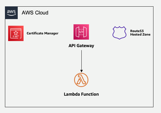
Figure 1: Sample architecture of API Gateway with Lambda backend
Use Network Load Balancer for cipher suite selection
We start with a scenario where a client interacts with the API gateway domain (for example, api.example.com) over a set of TLS/cipher combinations that are not acceptable for security reasons. In the subsequent steps, we will introduce a Network Load Balancer layer to frontend the API gateway domain without impacting the end-user interaction with the API gateway domain. In this section, we will walk you through how to make the application accessible through a Network Load Balancer and use ELB policies to exclude the TLS_ECDHE_RSA_WITH_AES_256_CBC_SHA384 cipher suite. In doing so, we will limit the operational overhead as much as possible, while keeping the application scalable, elastic, and highly available.
Figure 2 shows the solution that you will build.
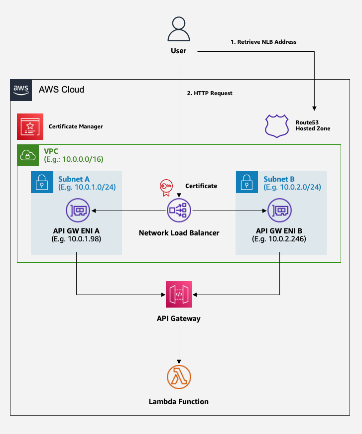
Figure 2: Target architecture, with a load balancer for cipher suite selection
The preceding diagram shows a workflow of the user interaction with the API gateway domain abstracted by the Network Load Balancer layer. For the first interaction, the user retrieves the API gateway domain from the Route 53 hosted zone. This API gateway domain aliases to the Network Load Balancer endpoint. In the next interaction, the user makes an HTTPS request to the domain endpoint with a TLS/cipher combination from the client side. The TLS connection is accepted or denied based on the security policy configured at the Network Load Balancer. In the rest of this post, we will walk you through how to set up this architecture.
Step 1: Create a VPC endpoint
The first step is to create a private VPC endpoint for API Gateway.
To create a VPC endpoint
- Open the Amazon VPC console.
- In the left navigation pane, choose Endpoints, and select Create endpoint.
- For Name tag, enter a name for your endpoint. For this walkthrough, we will enter MyEndPoint as the name for the endpoint.
- For Services, search for execute-api and select the service name, which will look similar to the following: com.amazonaws.<region-name>.execute-api.
- For VPC, select the VPC where you want to deploy the endpoint. For this walkthrough, we will use MyVPC as the VPC.
- For Subnets, select the private subnets where you want the private endpoint to be accessible. To help ensure high availability and resiliency, make sure that you select at least two subnets.
- (Optional) Specify the VPC endpoint policy to allow access to the VPC endpoint only for the desired users or services. Make sure that you apply the principle of least privilege.
- For Security Groups, select (or create) a security group for the API Gateway VPC endpoint. This security group will allow or deny traffic to the VPC endpoint. You can choose the ports and protocols along with the source and destination IP address range to allow for inbound and outbound traffic. In this example, you want the VPC endpoint to be accessed only from the Network Load Balancer, so make sure that you allow incoming traffic from the VPC’s Classless Inter-Domain Routing (CIDR) on port 443.
- Leave the other configuration options as they are, and then choose Create Endpoint. Wait until the VPC endpoint is deployed.
- When the VPC endpoint completes provisioning, take note of the endpoint ID and the IP addresses associated with it because you will need this information in the following steps. You will find one address for each subnet where you chose to deploy the VPC endpoint. After you select the newly created endpoint, you can find the assigned IP addresses in the Subnets tab.
Step 2: Associate API Gateway with the VPC endpoint and custom domain
The next step is to instruct the API Gateway to only accept invocations coming from the VPC endpoint, and then map your APIs with the custom domain name.
To associate API Gateway with the VPC endpoint and custom domain
- Open the Amazon API Gateway console and take note of the ID of your API.
- Choose your existing API in the console. For this walkthrough, we will use an API called MyAPI.
- In the left navigation pane, under API: <MyAPI>, choose Resource Policy.
- Paste the following policy, and replace <region-id>, <account-id>, <api-id>, and <endpoint-id> with your own information:
- In the left navigation pane, under API: <MyAPI>, choose Settings.
- In the Endpoint Configuration section, for VPC Endpoint IDs, enter your VPC endpoint ID.
- Leave the other configuration options as they are and choose Save Changes.
- In the left navigation pane, under API: <MyAPI>, choose Resources.
- Choose Actions and select Deploy API.
- Select an existing stage, or if you haven’t created one yet, select [New Stage] and enter a name for the stage (for example, prod). Then choose Deploy.
- Navigate back to the Amazon API Gateway console, and in the left navigation pane, choose Custom domain names.
- Choose Create.
- For Domain name, enter the full domain name that you plan to associate with your API Gateway (for example, api.example.com).
- For ACM certificate, select the certificate for the domain that you own (for example, *.example.com).
- Leave the rest as it is and choose Create domain name.
- Select the domain name that you just associated with API Gateway and select API mappings.
- Choose Configure API Mapping.
- For API, select your API, and for Stage, select your preferred stage.
- Leave the other configuration options as they are, and choose Save.
Step 3: Create a new target group for Network Load Balancer
Before creating a Network Load Balancer, you need to create a target group that it will redirect the requests to. You will configure the target group to redirect requests to the VPC endpoint.
To create a new target group for Network Load Balancer
- Open the Amazon EC2 console.
- In the left navigation pane, choose Target groups, and then choose Create target group.
- For Choose a target type, select IP addresses.
- For Target group name, enter your desired target group name. For this walkthrough, we will enter MyGroup as the target group name.
- For Protocol, select TLS.
- For Port, enter 443.
- Select MyVPC.
- Under Heath check protocol, select HTTPS, and under Health check path, enter /ping.
- Leave the rest as it is and choose Next.
- For Network, select MyVPC.
- Choose Add IPv4 address and add the IP addresses associated with the VPC endpoint one by one (these are the IP address associated with the VPC endpoint and detailed in step 10 of the section Step 1: Create a VPC endpoint).
- For Ports, enter 443, and then choose Include as pending below.
- Choose Create target group, and then wait for the target group to complete creation.
Step 4: Create a Network Load Balancer
Now you can create the Network Load Balancer. You will configure it to redirect traffic to the target group that you defined in Step 3.
To create the Network Load Balancer
- Open the Amazon EC2 console.
- In the left navigation pane, choose Load Balancers, and then choose Create load balancer.
- In the Network Load Balancer section, choose Create.
- For Load balancer name, enter a name for your load balancer. For this walkthrough, we will use the name MyNLB.
- For Scheme, select Internal.
- For VPC, select MyVPC.
- For Mappings, select the same subnets that you selected when you created the VPC endpoint in Step 1: Create a VPC endpoint.
- In the Listeners and routing section, for Port, enter 443.
- Forward the traffic to MyGroup.
- Select a security policy that excludes the cipher suites that you don’t want to allow. To learn more about the available policies, see Security policies. In this example, we will select ELBSecurityPolicy-TLS13-1-2-Res-2021-06, which excludes the TLS_ECDHE_RSA_WITH_AES_256_CBC_SHA384 cipher.
- For Default SSL cert, choose Select a certificate and then select your certificate (for example, *.example.com).
- Leave the rest as it is and choose Create load balancer. Wait for the load balancer to complete deployment.
Step 5: Set up DNS forwarding
The final step is to configure the Domain Name System (DNS) to associate the custom domain name with our APIs.
To set up DNS forwarding
- Open the Route53 console.
- In the left navigation pane, choose Hosted zones.
- Select the private hosted zone that manages your domain.
- Choose Create record.
- For Record name, enter the domain name that you plan to associate with your API (for example, api.example.com — the same name as in Step 2: Associate API Gateway with the VPC endpoint and custom domain).
- For Record type, leave the default A – Routes traffic to an IPV4 address and some AWS resources.
- Turn on Alias.
- For Route traffic to, select Alias to Network Load Balancer. Select the AWS Region where you deployed your resources and then select your load balancer.
- Choose Create records.
Step 6: Validate your solution
At this point, you have deployed the resources that you need to implement the solution. You now need to validate that it works as expected.
Your resources are deployed in private subnets, so you need to test them by sending requests from within the private subnet itself. For example, you can do that by connecting to a Linux instance that you have running inside the private subnet.
After you have logged in to your private EC2 instance, you can validate your solution by sending requests to your endpoint.
From your terminal of choice, run the following commands. Replace <endpoint> with your chosen domain name—for example, api.example.com/<your-path>.
This command sends a GET request to API Gateway by selecting a cipher suite that’s allowed by the ELB policy. As a result, the Network Load Balancer allows the connection and returns success.
This command sends a GET request to the API Gateway by selecting a cipher suite that is excluded by the ELB policy. As a result, the Network Load Balancer denies the connection and returns an error response.
Figure 3 shows the expected behavior.
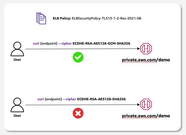
Figure 3: Target behavior: accept only connections with selected cipher suites
Conclusion
In this blog post, you learned how to use a Network Load Balancer as a reverse proxy for your private APIs managed by Amazon API Gateway. With this solution, the Network Load Balancer allows you to exclude specific cipher suites by selecting the ELB policy that’s most appropriate for your use case.
If you have feedback about this post, submit comments in the Comments section below. If you have questions about this post, contact AWS Support.
Want more AWS Security news? Follow us on Twitter.


